western mining electric association san antonio tx … papers/transformer-layer-vs... · western...
TRANSCRIPT

Western Mining Electric Association San Antonio TX Layer vs. Disk Windings Discussion NOVEMBER 15, 2012
© SPX Transformer Solutions, Inc.

Layer vs. Disk Windings Discussion
PRESENTED BY
David L. Harris, PE
Customer Technical Executive
SPX Transformer Solutions, Inc.
Office: 262-521-0166
Cell: 262-617-3039
Dave has a BS Electrical Engineering from Clarkson University, Potsdam, New York, and an MS
Engineering Management from Milwaukee School of Engineering. He has been in the transformer
industry for 43 years in design, development, manufacturing, testing, marketing, sales and
management of transformers and load tap changers. Currently, he holds the position of Customer
Technical Executive for SPX Transformer Solutions. Dave is a Life Member of the IEEE and is
active in the Electric Power Industry as a past chair of several Working Groups and
Subcommittees for the IEEE Substations Committee and IEEE Transformers Committee. Dave is
an individual member of CIGRE.

Layer vs. Disk Windings Discussion © SPX Transformer Solutions, Inc.
Thermal Performance
Mechanical Performance
Failure Photos
Questions
Agenda
3

Layer vs. Disk Windings Discussion © SPX Transformer Solutions, Inc.
Rectangular, Layer-Type Transformers
4

Layer vs. Disk Windings Discussion © SPX Transformer Solutions, Inc.
Transformer Winding Conductors
Copper Strip or Foil
Bus bar
Rectangular wire (MW)
Continuously Transposed Cable (CTC)
CTC
MW
5

Layer vs. Disk Windings Discussion © SPX Transformer Solutions, Inc.
Winding Types
SLL / Layer / Barrel
6
Layer vs. Disk Windings Discussion © SPX Transformer Solutions, Inc.
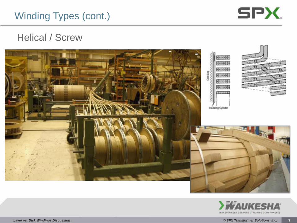
Helical / Screw
Winding Types (cont.)
7

Layer vs. Disk Windings Discussion © SPX Transformer Solutions, Inc.
Continuous Disk Winding
Winding Types (cont.)
Inner cross-over Outer cross-over
8

Layer vs. Disk Windings Discussion © SPX Transformer Solutions, Inc.
Circular, Layer-Type Transformers
9
Layer vs. Disk Windings Discussion © SPX Transformer Solutions, Inc.
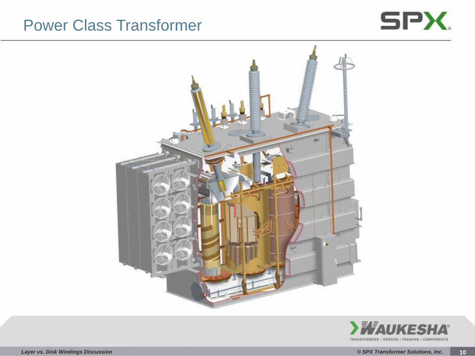
Power Class Transformer
10

Layer vs. Disk Windings Discussion © SPX Transformer Solutions, Inc.
Layer Winding Conductor Arrangements
11

Layer vs. Disk Windings Discussion © SPX Transformer Solutions, Inc.
Layer Type Windings
Very large “thermal mass” of conductor and insulation between cooling
ducts: difficult to calculate and control the hot spot temperatures
No radial ducts, some axial ducts, most of them just on ends, not all
around
Layer Winding Thermal Performance
12

Layer vs. Disk Windings Discussion © SPX Transformer Solutions, Inc.
Thermal Performance
Non-directed flow Directed flow
Disk Type Windings All turns are in contact with MOVING oil to lower hot spot temperatures
13
Layer vs. Disk Windings Discussion © SPX Transformer Solutions, Inc.
Thermal Performance
Adobe Acrobat Document
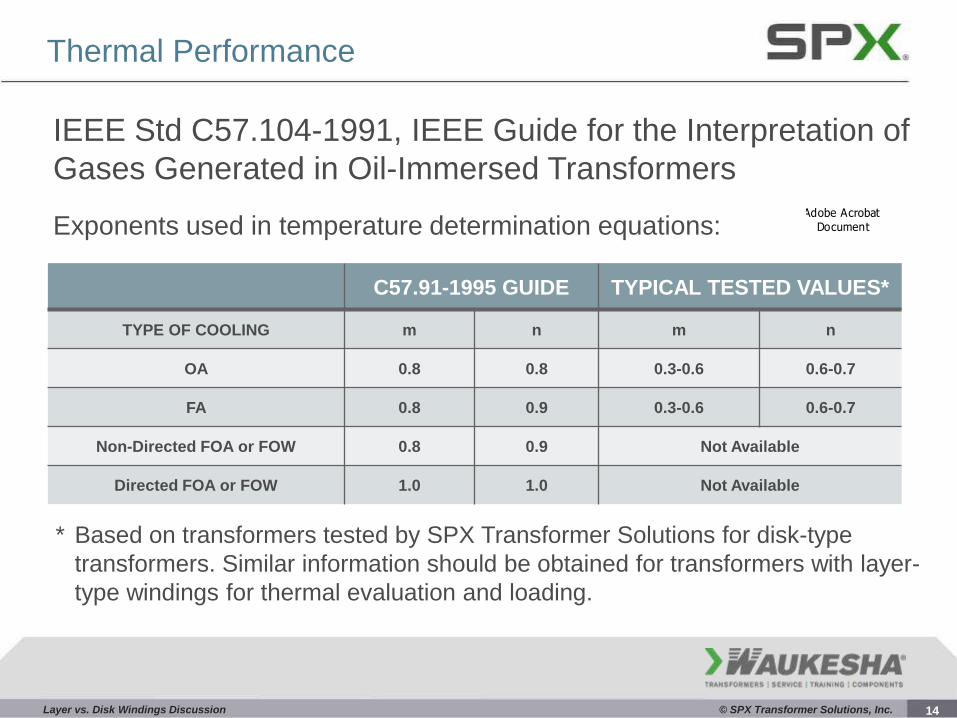
IEEE Std C57.104-1991, IEEE Guide for the Interpretation of
Gases Generated in Oil-Immersed Transformers
Exponents used in temperature determination equations:
C57.91-1995 GUIDE TYPICAL TESTED VALUES*
TYPE OF COOLING m n m n
OA 0.8 0.8 0.3-0.6 0.6-0.7
FA 0.8 0.9 0.3-0.6 0.6-0.7
Non-Directed FOA or FOW 0.8 0.9 Not Available
Directed FOA or FOW 1.0 1.0 Not Available
* Based on transformers tested by SPX Transformer Solutions for disk-type
transformers. Similar information should be obtained for transformers with layer-
type windings for thermal evaluation and loading.
14

Layer vs. Disk Windings Discussion © SPX Transformer Solutions, Inc.
Thermal Performance (cont.)
A four-level criterion has been developed to classify risks to transformers, when there is no
previous dissolved gas history, for continued operation at various combustible gas levels. The
criterion uses both concentrations for separate gases and the total concentration of all
combustible gases (see Table 1 on next slide).
Condition 1: TDCG below this level indicates the transformer is operating satisfactorily. Any
individual combustible gas exceeding specified levels should prompt additional investigation.
Condition 2: TDCG within this range indicates greater than normal combustible gas level. Any
individual combustible gas exceeding specified levels should prompt additional investigation.
Action should be taken to establish a trend. Fault(s) may be present.
Condition 3: TDCG within this range indicates a high level of decomposition. Any individual
combustible gas exceeding specified levels should prompt additional investigation.
Immediate action should be taken to establish a trend. Fault(s) are probably present.
Condition 4: TDCG within the range indicates excessive decomposition. Continued operation
could result in failure of the transformer. Proceed immediately and with caution.
15

Layer vs. Disk Windings Discussion © SPX Transformer Solutions, Inc.
Thermal Performance
TABLE 1 - DISSOLVED GAS CONCENTRATIONS
DISSOLVED KEY GAS CONCENTRATION LIMITS (ppm*)
STATUS H2 CH4 C2H2 C2H4 C2H6 CO CO2 TDCG†
CONDITION 1 100 120 35 50 65 350 2500 720
CONDITION 2 101-700 121-400 36-50 51-100 66-100 351-570 2500-4000 721-1920
CONDITION 3 701-1800 401-1000 51-80 101-200 101-150 571-1400 4001-10000 1921-4630
CONDITION 4 >1800 >1000 >80 >200 >150 >1400 >10000 >4630
IEEE Std C57.104-1991, IEEE Guide for the Interpretation
of Gases Generated in Oil-Immersed Transformers
Defines various conditions and limits of gases for each condition:
16
Layer vs. Disk Windings Discussion © SPX Transformer Solutions, Inc.
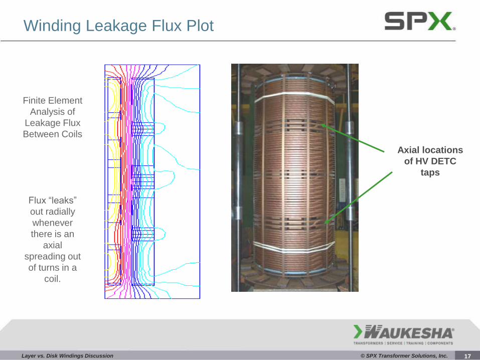
Winding Leakage Flux Plot
Axial locations
of HV DETC
taps
Flux “leaks”
out radially
whenever
there is an
axial
spreading out
of turns in a
coil.
Finite Element
Analysis of
Leakage Flux
Between Coils
17
Layer vs. Disk Windings Discussion © SPX Transformer Solutions, Inc.
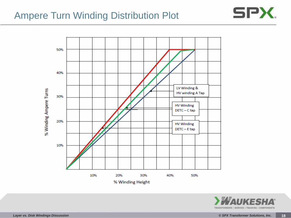
Ampere Turn Winding Distribution Plot
18

Layer vs. Disk Windings Discussion © SPX Transformer Solutions, Inc.
LV and TV Winding Turn Spreading
19

Layer vs. Disk Windings Discussion © SPX Transformer Solutions, Inc.
Short Circuit Winding Mechanical Performance
Short circuit forces pulsate at twice system frequency
Major and minor pulses gradually become equal as the offset current decays and the fault current becomes symmetrical
20

Layer vs. Disk Windings Discussion © SPX Transformer Solutions, Inc.
Layer Winding Short Circuit Performance
Fig B2
Forces acting on both the HV and LV windings of a simplified rectangular two-winding core-type transformer during through fault conditions.
21

Layer vs. Disk Windings Discussion © SPX Transformer Solutions, Inc.
Mechanical Performance
22

Layer vs. Disk Windings Discussion © SPX Transformer Solutions, Inc.
Short Circuit Mechanical Performance
Power Class transformers are
designed to withstand forces in
all directions.
Radial Forces – Buckling (inner coil)
Radial Forces – Hoop Stress (outer coil) Outward Radial Force converted to Tensile Stress
Axial Forces (Applying Left Hand Rule)
23

Layer vs. Disk Windings Discussion © SPX Transformer Solutions, Inc.
(I) (Br)
(Fa)
Axial Forces – Applying Left Hand Rule
Flux (B)
Current (I)
Force (F)
l = -Wks
2 π ROD
m
Length of beam:
24

Layer vs. Disk Windings Discussion © SPX Transformer Solutions, Inc.
Conductor Telescoping Failure
Design for Short Circuit Duty
Typically a problem for “Layer”
windings
Can happen to “disk” or “helical”
windings
Extent of damage to paper
insulation will determine how soon
a total unit failure will happen
25
Layer vs. Disk Windings Discussion © SPX Transformer Solutions, Inc.
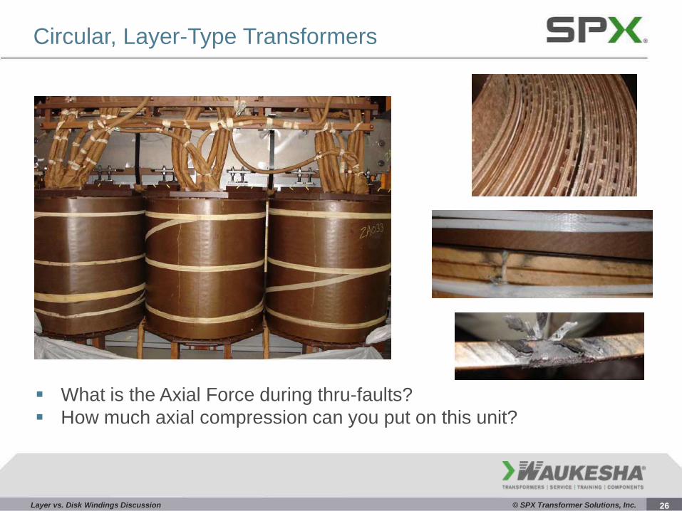
Circular, Layer-Type Transformers
What is the Axial Force during thru-faults?
How much axial compression can you put on this unit?
26

Layer vs. Disk Windings Discussion © SPX Transformer Solutions, Inc.
Failure Photos
27

Layer vs. Disk Windings Discussion © SPX Transformer Solutions, Inc.
Failure Photos (cont.)
28
Layer vs. Disk Windings Discussion © SPX Transformer Solutions, Inc.
Failure Photos (cont.)
29

Layer vs. Disk Windings Discussion © SPX Transformer Solutions, Inc.
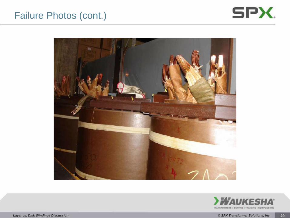
Failure Photos (cont.)
30
Layer vs. Disk Windings Discussion © SPX Transformer Solutions, Inc.
Failure Photos (cont.)
31
Layer vs. Disk Windings Discussion © SPX Transformer Solutions, Inc.
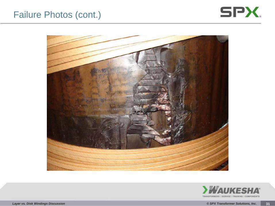
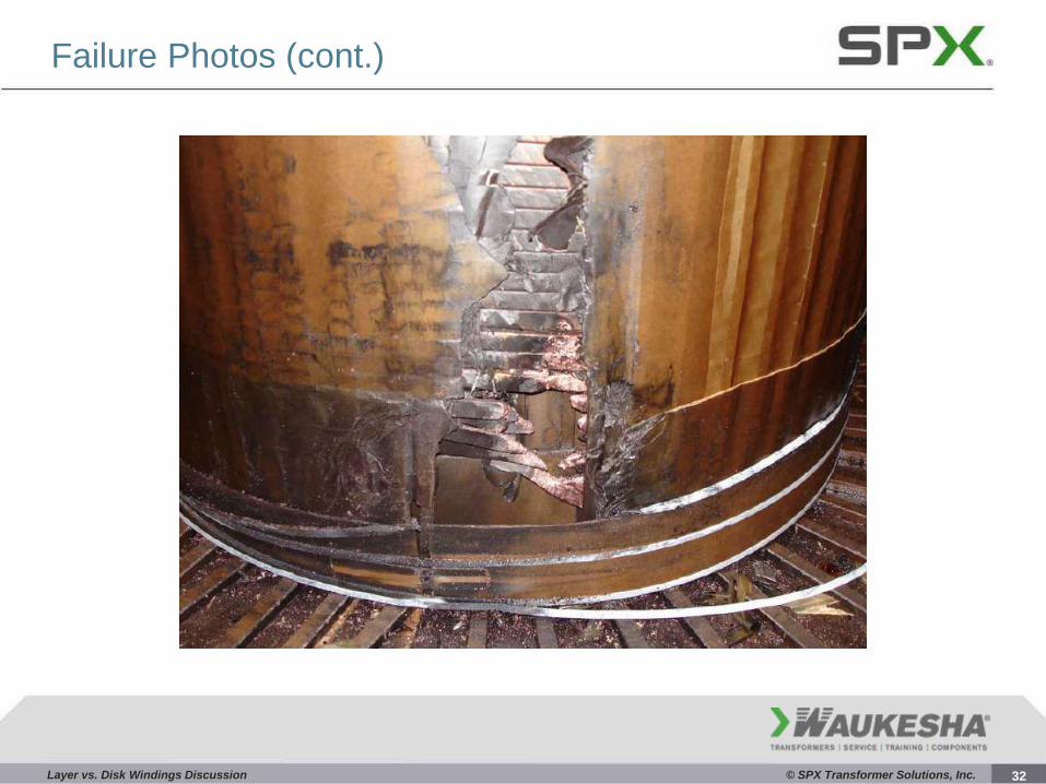
Failure Photos (cont.)
32

Layer vs. Disk Windings Discussion
33
Questions?
Thank You!