wem-mx-333mv integrated meter installation guidelines … · wem-mx-333mv integrated meter...
TRANSCRIPT

Energy Tracking, LLC 1 of 14 2/8/2013
WEM-MX-333mV
Integrated Meter Installation Guidelines Energy Tracking, LLC
Dated: February 8, 2013 By: Support Staff
Table of Contents
Enclosure Mounting ..................................................................... 2
High Voltage Wiring Type ............................................................. 4
High Voltage Fusing Options: ........................................................ 4 Wiring Diagram and Instructions ................................................... 5
Common Mistakes: ...................................................................... 7 Wiring Diagram:.......................................................................... 8
Powering the WEM-MX Meter ........................................................ 9 Accessing the WEM-MX 333mV Meter ............................................ 9
Log-In to the Meter ....................................................................10 Commissioning the Installation ....................................................13
Ordering Details:........................................................................14
Integrated Meter Enclosure – Figure 1.

Energy Tracking, LLC 2 of 14 2/8/2013
Enclosure Mounting:
The Integrated Meter Enclosure (IMC) is a UL approved IP 45 external
enclosure that can be mounted indoors or outdoors. This publication provides installation guidelines for mounting it on various surfaces.
This enclosure has 4 mounting holes to mount the enclosure.
The external enclosure incorporated with the WEM-MX 333mV meter enclosure, circuit breaker and power supply weighs 5 lbs. The
mounting of the enclosure must be done on an even flat surface.
Note: Failure to wear safety glasses with side shields can result in serious personal injury. Always wear ANSI compliant eye protection.
Mounting to Brick, Block or Concrete:
1. Use concrete anchors ¼” (diameter) X 1-3/4” (length). These
are commonly available in from local hardware distributors such
as Lowes or Home Depot. We recommend the Buildex Tapcon™ concrete anchors which are corrosion resistant or use
similar in capability and performance.
2. Drill a hole using a hammer drill 3/16” drill bit to 1-3/4” in depth.
3. Drive the anchor nut using the hammer drill with nut driver until
fully seated for all four mounting locations as shown below in Figure 2 & 3.
Figure 2 – Bottom View

Energy Tracking, LLC 3 of 14 2/8/2013
Figure 3 – Bottom View
Figure 4 – WEM-MX 333mV meter
IMPORTANT: If you have not purchased an external enclosure from
Energy Tracking then the meter must be installed in a UL Listed UL50 enclosure.
Mounting Screws: Please use #6 X 1/2" self-tapping screws.
Phillips/Pan Head/ Type A / 18-8 Stainless Steel.
Internal Enclosure Dimensions: 7.0” (L) X 4.0” (W) X 2.3” (H).
Integrated Meter Enclosure Dimensions: 12.1” (L) X 7.0” (W) X 7.4” (H).
Environment: -20 deg C to +60 deg C.
Energy Tracking, LLC 4 of 14 2/8/2013
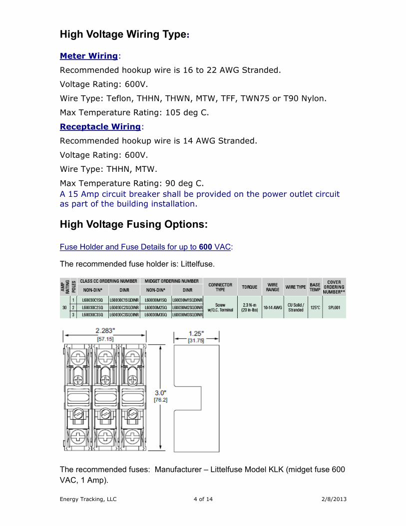
High Voltage Wiring Type:
Meter Wiring:
Recommended hookup wire is 16 to 22 AWG Stranded.
Voltage Rating: 600V.
Wire Type: Teflon, THHN, THWN, MTW, TFF, TWN75 or T90 Nylon.
Max Temperature Rating: 105 deg C.
Receptacle Wiring:
Recommended hookup wire is 14 AWG Stranded.
Voltage Rating: 600V.
Wire Type: THHN, MTW.
Max Temperature Rating: 90 deg C.
A 15 Amp circuit breaker shall be provided on the power outlet circuit
as part of the building installation.
High Voltage Fusing Options:
Fuse Holder and Fuse Details for up to 600 VAC: The recommended fuse holder is: Littelfuse.
The recommended fuses: Manufacturer – Littelfuse Model KLK (midget fuse 600
VAC, 1 Amp).
Energy Tracking, LLC 5 of 14 2/8/2013
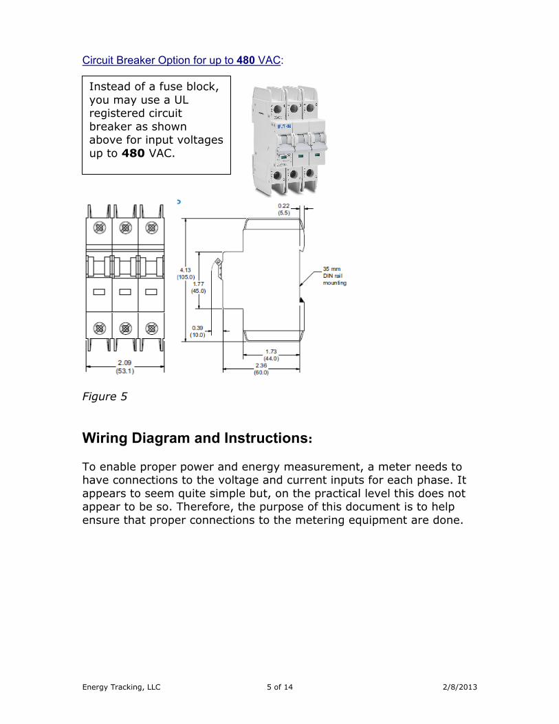
Circuit Breaker Option for up to 480 VAC:
Figure 5
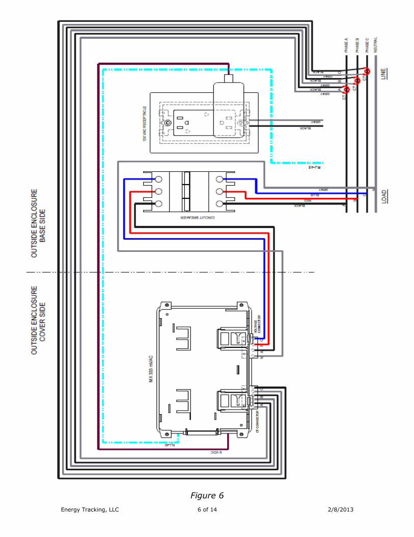
Wiring Diagram and Instructions:
To enable proper power and energy measurement, a meter needs to have connections to the voltage and current inputs for each phase. It
appears to seem quite simple but, on the practical level this does not appear to be so. Therefore, the purpose of this document is to help
ensure that proper connections to the metering equipment are done.
Instead of a fuse block,
you may use a UL registered circuit
breaker as shown above for input voltages
up to 480 VAC.
Energy Tracking, LLC 6 of 14 2/8/2013
Figure 6

Energy Tracking, LLC 7 of 14 2/8/2013
Common Mistakes:
The following are the most common mistakes done during installation
of a meter and associated current measurement transformers (CTs) inputs.
a. The voltage connections for the respective phases A, B & C (L1,
L2, & L3) must match the voltage designated inputs to the meter. Each phase must be confirmed to ensure it matches the
voltage measurement input to the meter.
b. The current transformer connections for the respective phases A, B & C must match the associated voltage phases to the meter.
i.e.; Phase ‘A’ CT must be routed through the phase ‘A’ voltage
conductor. Each phase must be confirmed to ensure it matches the current measurement input to the meter.
c. The current transformer(s) need to be oriented properly. Each
current transformer will have either an arrow or orientation of the output secondary leads (X2, X1) that should point towards
the load. No damage will occur to the meter if incorrectly installed. The power factor for each phase will be displayed as a
negative value indicating power flow in the opposite direction. See note below in (d). To correct, flip the current transformer(s)
until all phases report positive power factors.
d. Note: From an electric utility’s perspective energy “delivered” or “imported” is energy flow from the grid to the load / building.
Energy “received” or “exported” is flow of energy from the load /
building to the grid which can occur when metering a solar power plant or onsite generator. When installing a “NET” meter
where energy flows in both directions need to recorded, you must enable the 4 quadrant logging in the meter.
Click on ‘Setup >> Schedule Reporting & Setup’.
Enable the checkbox and click the “Submit” button.
Figure 7

Energy Tracking, LLC 8 of 14 2/8/2013
Wiring Diagram: Three Phase – 4 Wire WYE Connection WEM-MX 333mV:
Check for CT label ‘THIS SIDE TOWARDS SOURCE’ on the CT always faces the LINE.
Figure 8
LINE
PHASE C
PHASE B
PHASE A
LOAD
CT
CT
CT
Web Enabled Meter – MX 333 mVAC
VOLTAGE CONNECTOR C B A N
CT CONNECTOR
C B A
NEUTRAL
Polarity is important
CT
orientation important
FUSE BLOCK
MAX 0.333 VAC INPUT
9VDC INPUT
RJ45 Ethernet Jack
Energy Tracking, LLC 9 of 14 2/8/2013
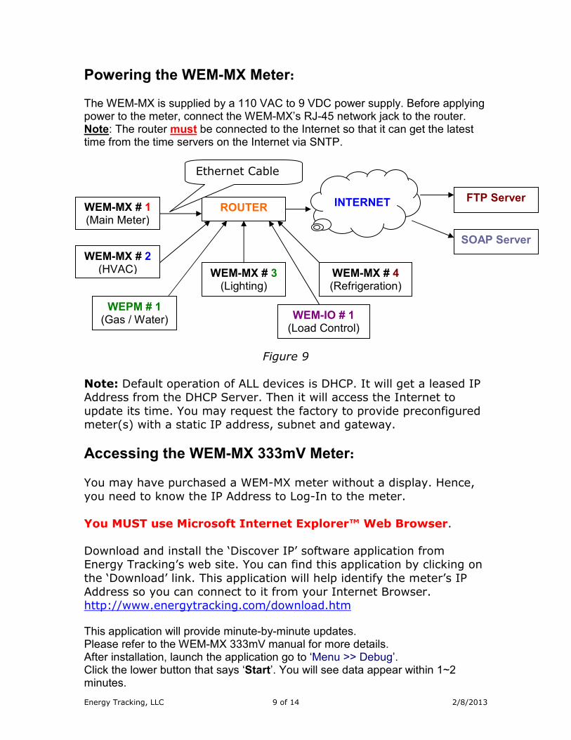
Powering the WEM-MX Meter: The WEM-MX is supplied by a 110 VAC to 9 VDC power supply. Before applying power to the meter, connect the WEM-MX’s RJ-45 network jack to the router. Note: The router must be connected to the Internet so that it can get the latest time from the time servers on the Internet via SNTP.
Figure 9
Note: Default operation of ALL devices is DHCP. It will get a leased IP Address from the DHCP Server. Then it will access the Internet to
update its time. You may request the factory to provide preconfigured meter(s) with a static IP address, subnet and gateway.
Accessing the WEM-MX 333mV Meter: You may have purchased a WEM-MX meter without a display. Hence,
you need to know the IP Address to Log-In to the meter.
You MUST use Microsoft Internet Explorer™ Web Browser.
Download and install the ‘Discover IP’ software application from Energy Tracking’s web site. You can find this application by clicking on
the ‘Download’ link. This application will help identify the meter’s IP
Address so you can connect to it from your Internet Browser. http://www.energytracking.com/download.htm This application will provide minute-by-minute updates. Please refer to the WEM-MX 333mV manual for more details. After installation, launch the application go to ‘Menu >> Debug’. Click the lower button that says ‘Start’. You will see data appear within 1~2 minutes.
WEM-MX # 1 (Main Meter)
ROUTER
INTERNET FTP Server
SOAP Server
WEM-MX # 2 (HVAC) WEM-MX # 3
(Lighting) WEM-MX # 4 (Refrigeration)
WEPM # 1 (Gas / Water) WEM-IO # 1
(Load Control)
Ethernet Cable

Energy Tracking, LLC 10 of 14 2/8/2013
Figure 10
Once the IP Address is identified, log-in to the meter using an Internet
Browser MS Internet Explorer. Note: You must use MS IE™
Log-In to the Meter:
http://xxx.xxx.xxx.xxx
Figure 11
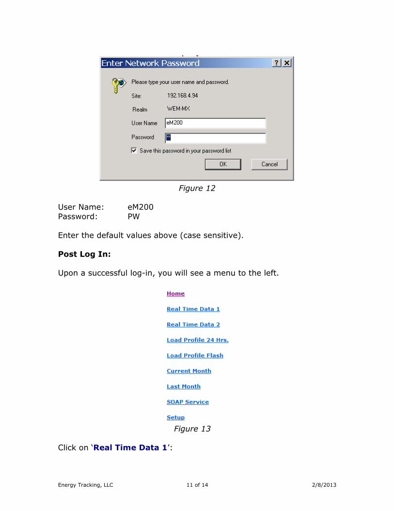
You should see the page shown above. Click on the ‘Log-In’ link and an authentication pop-up dialog will appear.
Energy Tracking, LLC 11 of 14 2/8/2013
Figure 12
User Name: eM200
Password: PW
Enter the default values above (case sensitive).
Post Log In:
Upon a successful log-in, you will see a menu to the left.
Figure 13
Click on ‘Real Time Data 1’:

Energy Tracking, LLC 12 of 14 2/8/2013
With no voltage or current inputs connected, you should see:
Figure 14
With voltage and current applied, you should see.
Figure 15
Note: Power factor values will typically be in-between 0.8 to 0.9.
Now, you can connect each voltage phase and confirm its proper
connection by clicking on the ‘Real Time Data 1’ link.
Next, connect each current transformer (CT) input and check the reading by phase by clicking on the ‘Real Time Data 1’ link.
Note: If after connecting the CT, the Power Factor value is negative,
then the CT is not oriented properly. The CT orientation must be reversed. If you are installing the meter at a location where only the
absolute current flow needs to be measured; you can disable 4-quadrant measurement by:
Click on ‘Setup >> Schedule Reporting & Setup’.
Figure 16
Energy Tracking, LLC 13 of 14 2/8/2013
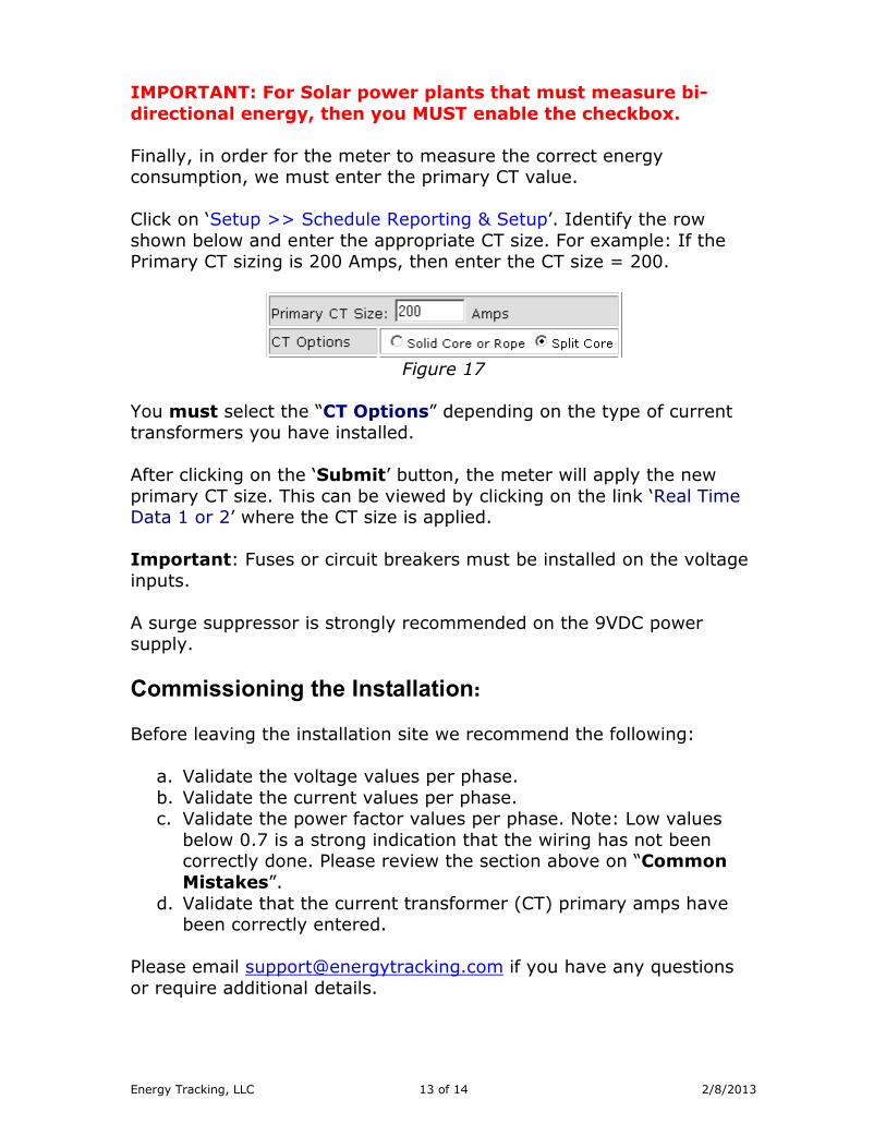
IMPORTANT: For Solar power plants that must measure bi-
directional energy, then you MUST enable the checkbox.
Finally, in order for the meter to measure the correct energy consumption, we must enter the primary CT value.
Click on ‘Setup >> Schedule Reporting & Setup’. Identify the row
shown below and enter the appropriate CT size. For example: If the Primary CT sizing is 200 Amps, then enter the CT size = 200.
Figure 17
You must select the “CT Options” depending on the type of current
transformers you have installed.
After clicking on the ‘Submit’ button, the meter will apply the new
primary CT size. This can be viewed by clicking on the link ‘Real Time Data 1 or 2’ where the CT size is applied.
Important: Fuses or circuit breakers must be installed on the voltage
inputs.
A surge suppressor is strongly recommended on the 9VDC power supply.
Commissioning the Installation:
Before leaving the installation site we recommend the following:
a. Validate the voltage values per phase.
b. Validate the current values per phase. c. Validate the power factor values per phase. Note: Low values
below 0.7 is a strong indication that the wiring has not been correctly done. Please review the section above on “Common
Mistakes”.
d. Validate that the current transformer (CT) primary amps have been correctly entered.
Please email [email protected] if you have any questions
or require additional details.
Energy Tracking, LLC 14 of 14 2/8/2013
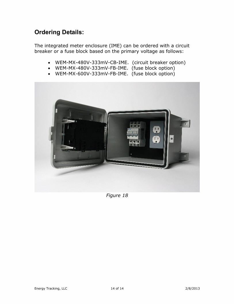
Ordering Details: The integrated meter enclosure (IME) can be ordered with a circuit
breaker or a fuse block based on the primary voltage as follows:
• WEM-MX-480V-333mV-CB-IME. (circuit breaker option) • WEM-MX-480V-333mV-FB-IME. (fuse block option)
• WEM-MX-600V-333mV-FB-IME. (fuse block option)
Figure 18