well stimulation techniques - … stimulation techniques workshop on technology imperatives for...
TRANSCRIPT

WELL STIMULATION TECHNIQUES
WORKSHOP ON TECHNOLOGY IMPERATIVES
FOREXPLORATION AND PRODUCTION OF OIL & GAS
(21-24 December), Sivasagar
Dr A K PandeyDGM(Chemistry)

Opening up new channels in the rock for the oil
and gas to flow through is called stimulation.
Three stimulation treatments are commonly used:
explosives to break up the rock, injection of acid to
partially dissolve the rock, and hydraulic fracturing
to split the rock and prop it open with proppants.

TYPES OF FORMATIONTYPES OF FORMATION
FORMATION DAMAGEFORMATION DAMAGE
ACIDIZATIONACIDIZATION
HYDRAULIC FRACTURINGHYDRAULIC FRACTURING
WATER SHUT OFF/ INJECTION PROFILE WATER SHUT OFF/ INJECTION PROFILE MODIFICATIONMODIFICATION
SAND CONTROLSAND CONTROL
COURSE OUTLINE
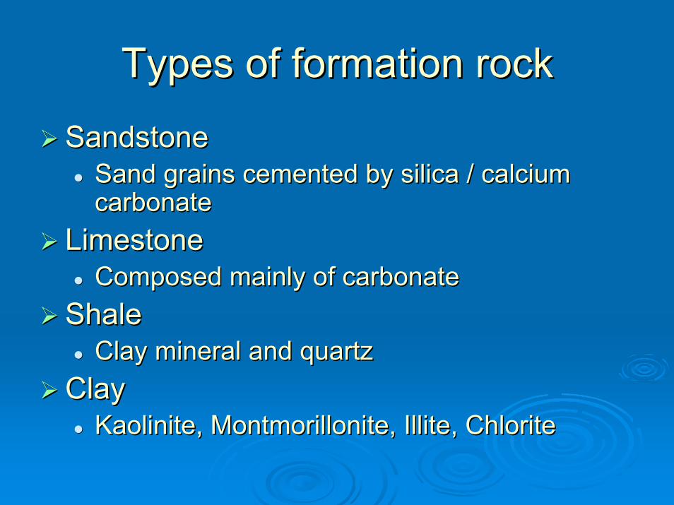
Types of formation rockTypes of formation rock
SandstoneSandstoneSand grains cemented by silica / calcium Sand grains cemented by silica / calcium carbonatecarbonate
LimestoneLimestoneComposed mainly of carbonateComposed mainly of carbonate
ShaleShaleClay mineral and quartzClay mineral and quartz
ClayClayKaolinite, Montmorillonite, Illite, ChloriteKaolinite, Montmorillonite, Illite, Chlorite
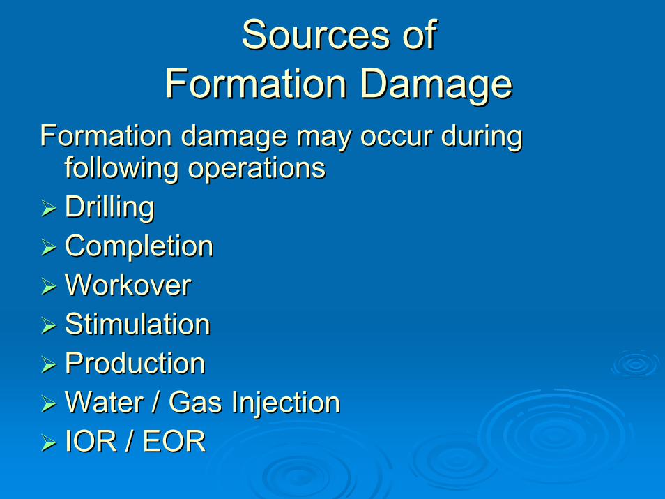
Sources of Sources of Formation DamageFormation Damage
Formation damage may occur during Formation damage may occur during following operationsfollowing operationsDrillingDrillingCompletion Completion Workover Workover Stimulation Stimulation Production Production Water / Gas Injection Water / Gas Injection IOR / EOR IOR / EOR
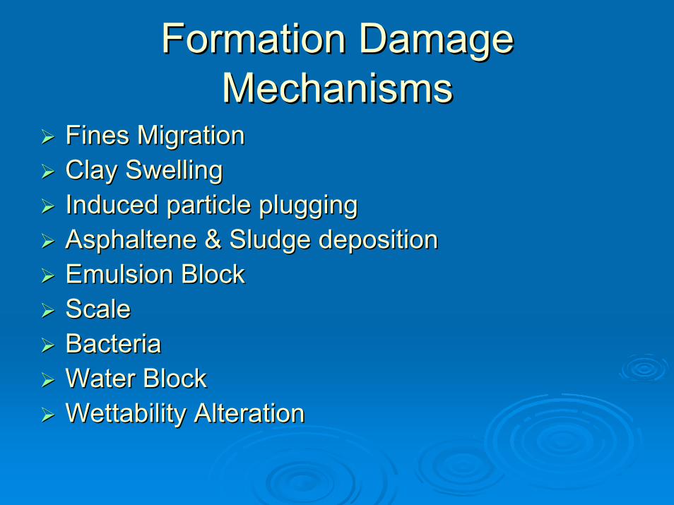
Formation Damage Formation Damage MechanismsMechanisms
Fines MigrationFines MigrationClay SwellingClay SwellingInduced particle pluggingInduced particle pluggingAsphaltene & Sludge depositionAsphaltene & Sludge depositionEmulsion BlockEmulsion BlockScaleScaleBacteriaBacteriaWater BlockWater BlockWettability AlterationWettability Alteration
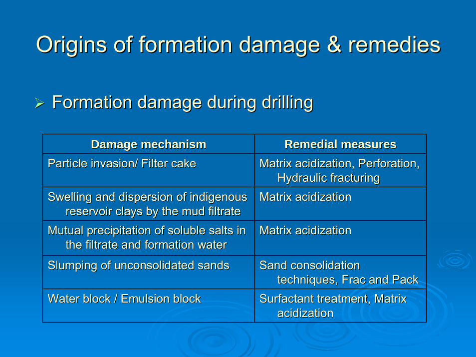
Origins of formation damage & remediesOrigins of formation damage & remedies
Formation damage during drillingFormation damage during drilling
Damage mechanismDamage mechanism Remedial measuresRemedial measuresParticle invasion/ Filter cakeParticle invasion/ Filter cake Matrix acidization, Perforation, Matrix acidization, Perforation,
Hydraulic fracturingHydraulic fracturingSwelling and dispersion of indigenous Swelling and dispersion of indigenous
reservoir clays by the mud filtratereservoir clays by the mud filtrateMatrix acidization Matrix acidization
Mutual precipitation of soluble salts in Mutual precipitation of soluble salts in the filtrate and formation waterthe filtrate and formation water
Matrix acidization Matrix acidization
Slumping of unconsolidated sandsSlumping of unconsolidated sands Sand consolidation Sand consolidation techniques, Frac and Packtechniques, Frac and Pack
Water block / Emulsion blockWater block / Emulsion block Surfactant treatment, Matrix Surfactant treatment, Matrix acidizationacidization

Formation damage (drilling)Formation damage (drilling)
Fracture Plugging
Shallow Matrix Damage
Filter cake
WellboreCross Section
Pore Plugging

Origins of formation damage & Origins of formation damage & remediesremedies
Formation Damage during cementingFormation Damage during cementingDamage mechanismDamage mechanism Remedial measuresRemedial measures
Fines migration from the cement Fines migration from the cement slurry into the formation slurry into the formation
Matrix acidization, Perforation, Matrix acidization, Perforation, Hydraulic fracturing Hydraulic fracturing
Precipitation of solids from the Precipitation of solids from the cement within the formation cement within the formation
Matrix acidization ,Perforation Matrix acidization ,Perforation
Precipitation of secondary minerals Precipitation of secondary minerals following reservoir mineral following reservoir mineral dissolution dissolution
Matrix acidization Matrix acidization

Damage by Overbalance Damage by Overbalance PerforationPerforation

Origins of formation damage & Origins of formation damage & remediesremedies
During Completion & WorkoverDuring Completion & WorkoverDamage mechanismDamage mechanism Remedial measuresRemedial measuresHydration and swelling of clay mineralsHydration and swelling of clay minerals Matrix acidization ,Clay stabilizationMatrix acidization ,Clay stabilization
Movement and plugging by clay size Movement and plugging by clay size particles in the formation particles in the formation
Matrix acidization ,Clay stabilization Matrix acidization ,Clay stabilization
Plugging by invading materials from the Plugging by invading materials from the wellbore fluids wellbore fluids
Matrix acidization Matrix acidization
Emulsion and water blocks due to lost Emulsion and water blocks due to lost wellbore fluidwellbore fluid
Surfactant treatment, Matrix Surfactant treatment, Matrix acidizationacidization
Relative permeability effectsRelative permeability effects Surfactant treatmentSurfactant treatment
Precipitation of scalesPrecipitation of scales AcidizationAcidization
Plugged perforations due to improper Plugged perforations due to improper perforating conditionsperforating conditions
Acidization, PerforationAcidization, Perforation
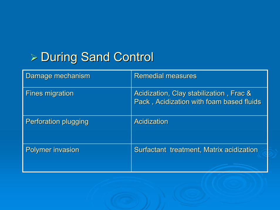
During Sand ControlDuring Sand ControlDamage mechanism Damage mechanism Remedial measures Remedial measures
Fines migration Fines migration Acidization, Clay stabilization , Frac & Acidization, Clay stabilization , Frac & Pack , Acidization with foam based fluids Pack , Acidization with foam based fluids
Perforation plugging Perforation plugging Acidization Acidization
Polymer invasion Polymer invasion Surfactant treatment, Matrix acidizationSurfactant treatment, Matrix acidization
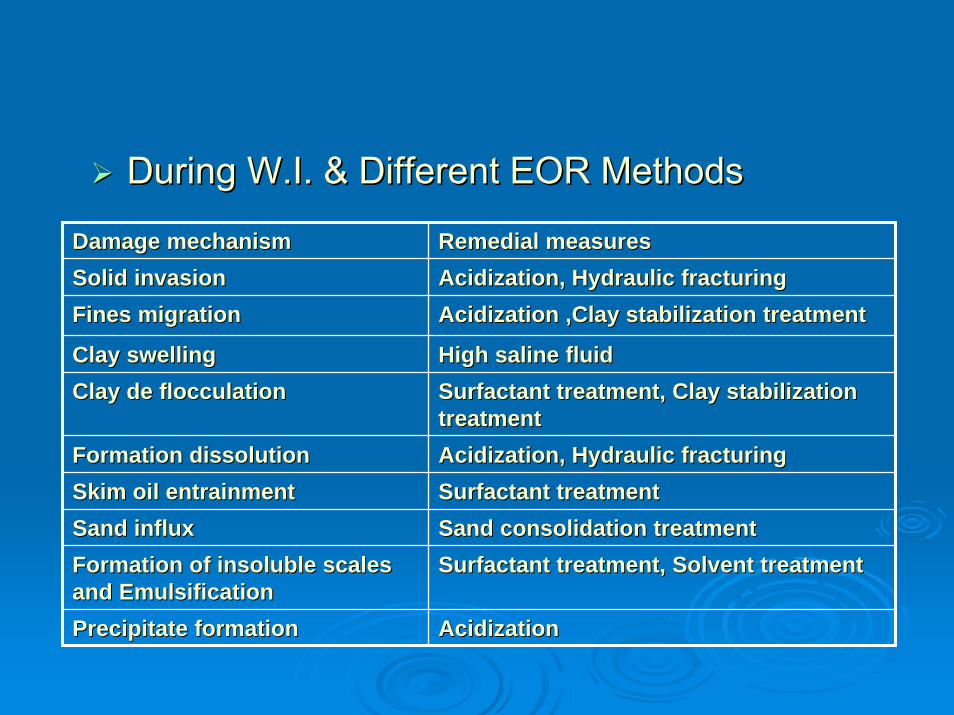
During W.I. & Different EOR MethodsDuring W.I. & Different EOR Methods
Damage mechanism Damage mechanism Remedial measures Remedial measures Solid invasionSolid invasion Acidization, Hydraulic fracturingAcidization, Hydraulic fracturingFines migrationFines migration Acidization ,Clay stabilization treatmentAcidization ,Clay stabilization treatment
Clay swellingClay swelling High saline fluidHigh saline fluidClay de flocculationClay de flocculation Surfactant treatment, Clay stabilization Surfactant treatment, Clay stabilization
treatmenttreatmentFormation dissolutionFormation dissolution Acidization, Hydraulic fracturingAcidization, Hydraulic fracturingSkim oil entrainmentSkim oil entrainment Surfactant treatmentSurfactant treatmentSand influxSand influx Sand consolidation treatmentSand consolidation treatmentFormation of insoluble scales Formation of insoluble scales and Emulsificationand Emulsification
Surfactant treatment, Solvent treatmentSurfactant treatment, Solvent treatment
Precipitate formationPrecipitate formation AcidizationAcidization
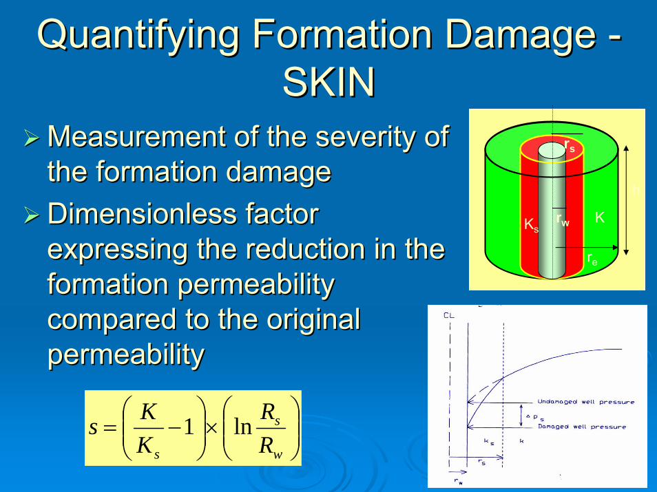
Quantifying Formation Damage Quantifying Formation Damage --SKINSKIN
Measurement of the severity of Measurement of the severity of the formation damage the formation damage Dimensionless factorDimensionless factorexpressing the reduction in the expressing the reduction in the formation permeability formation permeability compared to the original compared to the original permeabilitypermeability
rw
rs
re
KKs
h
⎟⎟⎠
⎞⎜⎜⎝
⎛×⎟⎟⎠
⎞⎜⎜⎝
⎛−=
w
s
s RR
KKs ln1
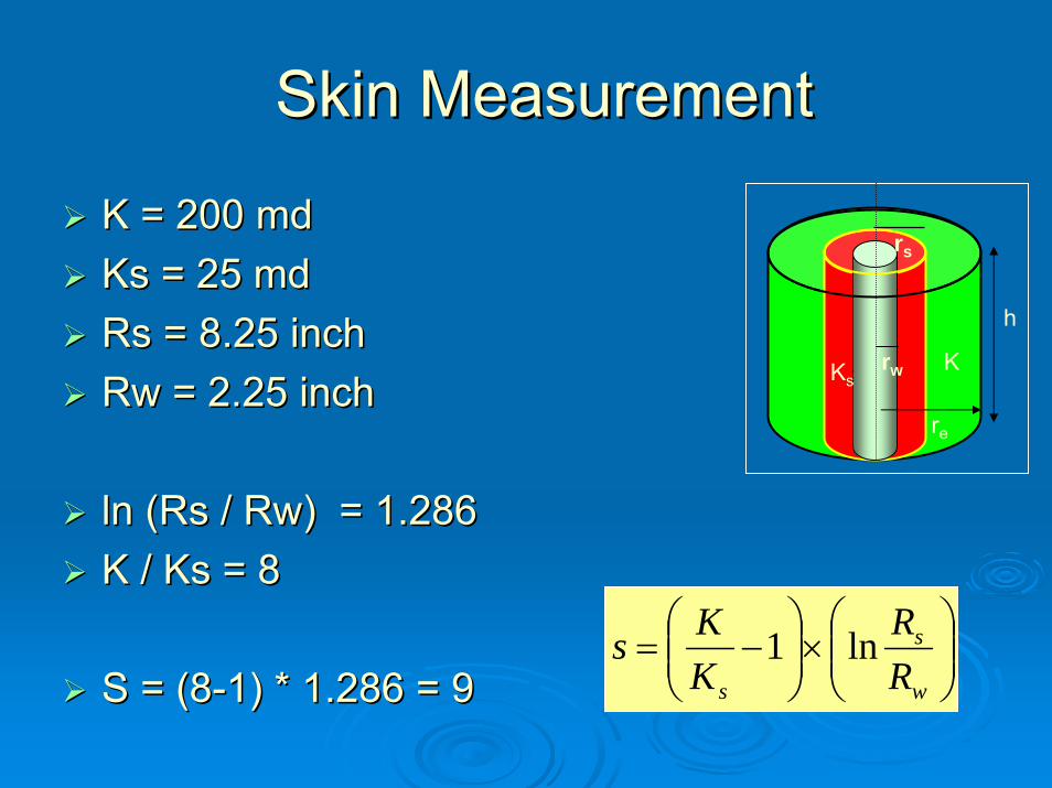
Skin MeasurementSkin Measurement
K = 200 K = 200 mdmdKs = 25 Ks = 25 mdmdRsRs = 8.25 inch= 8.25 inchRwRw = 2.25 inch= 2.25 inch
lnln ((RsRs / / RwRw) = 1.286) = 1.286K / Ks = 8K / Ks = 8
S = (8S = (8--1) * 1.286 = 91) * 1.286 = 9
rw
rs
re
KKs
h
⎟⎟⎠
⎞⎜⎜⎝
⎛×⎟⎟⎠
⎞⎜⎜⎝
⎛−=
w
s
s RR
KKs ln1

Skin : Effect on ProductionSkin : Effect on Production
⎟⎟⎠
⎞⎜⎜⎝
⎛+
−=
SrrB
ppkhq
w
e
wfr
ln2.141
)(
μ

Pressure Transient analysisPressure Transient analysis
Drawdown testDrawdown test
Build up testBuild up test
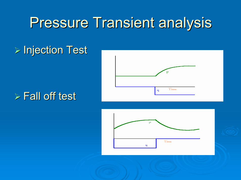
Pressure Transient analysisPressure Transient analysis
Injection TestInjection Test
Fall off testFall off test

ACIDIZATION

What is acidizationWhat is acidization
Matrix stimulation by acidization is Matrix stimulation by acidization is accomplished by injecting chemicals to accomplished by injecting chemicals to dissolve and/or disperse materials near dissolve and/or disperse materials near the wellbore that impair well production in the wellbore that impair well production in sandstones or to create new, unimpaired sandstones or to create new, unimpaired flow channels between the wellbore and a flow channels between the wellbore and a carbonate formation.carbonate formation.
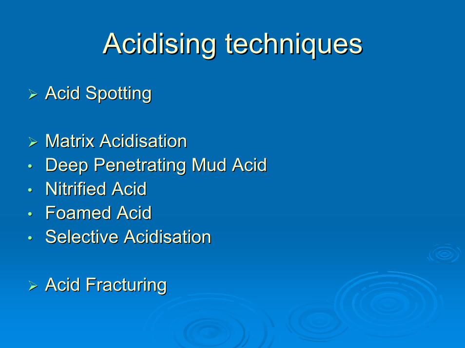
AcidisingAcidising techniquestechniquesAcid SpottingAcid Spotting
Matrix AcidisationMatrix Acidisation•• Deep Penetrating Mud AcidDeep Penetrating Mud Acid•• Nitrified AcidNitrified Acid•• Foamed AcidFoamed Acid•• Selective AcidisationSelective Acidisation
Acid FracturingAcid Fracturing

AcidizationAcid pumper
Res
ervo
irSh
ale
Shal
e
Well
1- 4ft
Remove near wellbore damage by injecting acid / reacting fluid into the formation below fracturing pressure
Acid
Displacing fluid

ACID PUMPERACID PUMPER
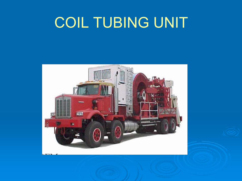
COIL TUBING UNIT

Mechanism of Matrix Acid job:Mechanism of Matrix Acid job:
To inject acid into formation at a pressure less To inject acid into formation at a pressure less than the pressure at which fracture can be than the pressure at which fracture can be openedopened
To dissolve the clays, mud solids near the To dissolve the clays, mud solids near the wellbore which had choked the pores wellbore which had choked the pores
To enlarge the pore spaces To enlarge the pore spaces To leave the sand and remaining fines in a To leave the sand and remaining fines in a
waterwater--wet conditionwet condition
Fluid SelectionFluid Selection
Acid TypeAcid Type
ConcentrationConcentration
VolumeVolume

Acid formulation Acid formulation
Lab studies involved
•Stimulation history•Acid solubility•Mineralogy (type of clay)•Emulsion test•Sludge test•Core flow study
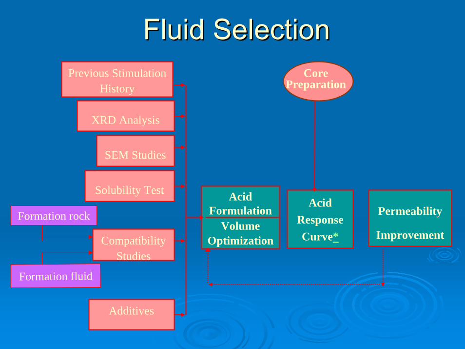
Fluid SelectionFluid SelectionPrevious Stimulation
History
XRD Analysis
SEM Studies
Solubility Test
Compatibility Studies
Acid Formulation
VolumeOptimization
Additives
Acid Response Curve*
Permeability
Improvement
Core Preparation
Formation rock
Formation fluid
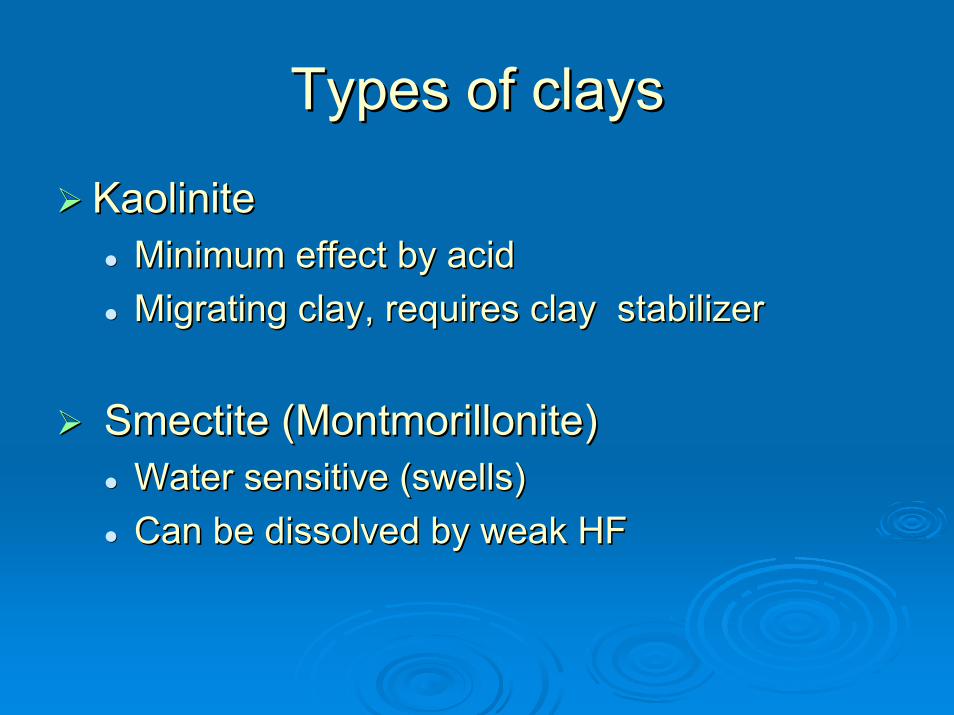
Types of claysTypes of clays
KaoliniteKaoliniteMinimum effect by acidMinimum effect by acidMigrating clay, requires clay stabilizerMigrating clay, requires clay stabilizer
SmectiteSmectite ((MontmorilloniteMontmorillonite))Water sensitive (swells)Water sensitive (swells)Can be dissolved by weak HFCan be dissolved by weak HF
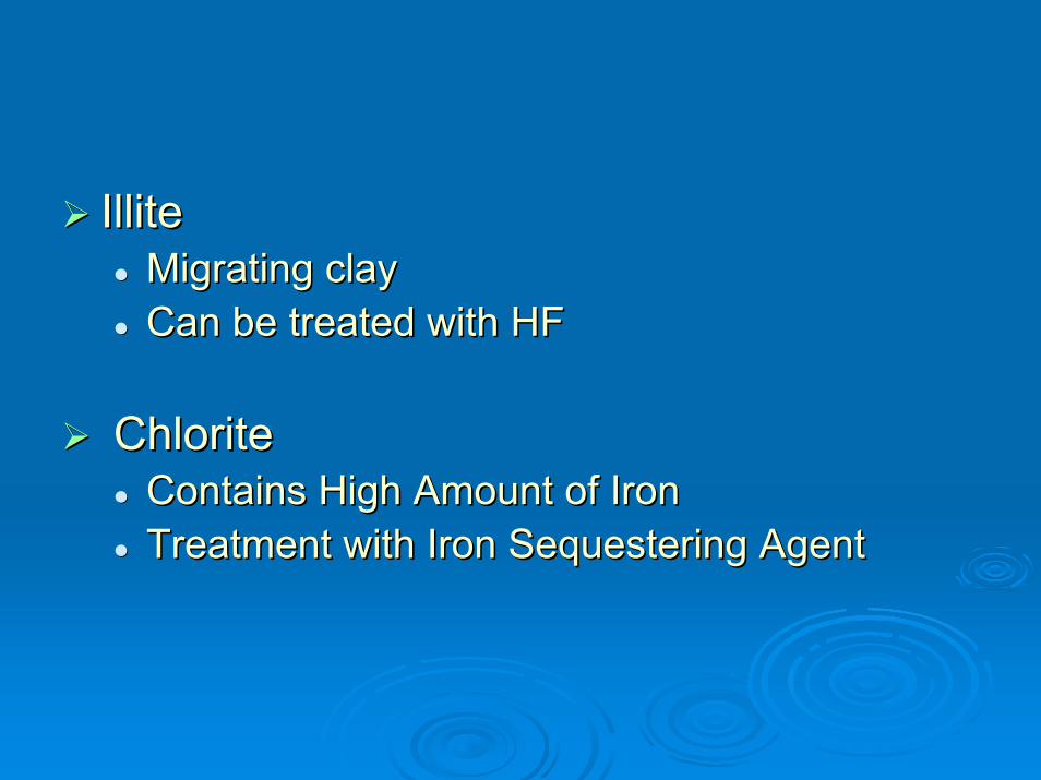
IlliteIlliteMigrating clayMigrating clayCan be treated with HFCan be treated with HF
ChloriteChloriteContains High Amount of IronContains High Amount of IronTreatment with Iron Sequestering AgentTreatment with Iron Sequestering Agent

Type of Acid Type of Acid
Carbonate reservoirsCarbonate reservoirsHClHCl is used as basic rock dissolution chemicalis used as basic rock dissolution chemical
Sandstone reservoirSandstone reservoirHClHCl + HF (mud acid) is used as basic rock + HF (mud acid) is used as basic rock dissolution chemicaldissolution chemical

Carbonate Carbonate acidisingacidisingCarbonate formations generally Carbonate formations generally have a low permeability and can have a low permeability and can be highly fissuredbe highly fissured
HCl is used as basic rock HCl is used as basic rock dissolution agentdissolution agent
Wormholes form in the process Wormholes form in the process of dissolution of rockof dissolution of rockOther additives are used as per Other additives are used as per compatibility with rock mineralscompatibility with rock minerals
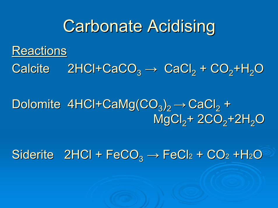
Carbonate Carbonate AcidisingAcidisingReactionsReactionsCalciteCalcite 2HCl+CaCO2HCl+CaCO33 →→ CaClCaCl22 + CO+ CO22+H+H22OO
DolomiteDolomite 4HCl+CaMg4HCl+CaMg((COCO33))2 2 →→ CaClCaCl22 + + MgClMgCl22+ 2CO+ 2CO22+2H+2H22O O
Siderite 2HCl + FeCOSiderite 2HCl + FeCO33 →→ FeClFeCl22 + CO+ CO22 +H+H22O O
Carbonate Carbonate acidisingacidisingFor effective stimulation deep worm For effective stimulation deep worm holes are necessary to maximize holes are necessary to maximize conductivity between reservoir and well conductivity between reservoir and well bore for enhancement of productionbore for enhancement of production
The reaction rate between conventional The reaction rate between conventional Plain HCl and carbonate is very fast at Plain HCl and carbonate is very fast at reservoir temperaturereservoir temperature

For effective stimulation of carbonate For effective stimulation of carbonate reservoir following acid systems are usedreservoir following acid systems are used
Emulsified acid systemEmulsified acid system•• Acid emulsified with hydrocarbon(diesel)Acid emulsified with hydrocarbon(diesel)
Gelled acid systemGelled acid system•• Acid modified with gelling agent Acid modified with gelling agent
(polymer/(polymer/viscoelasticviscoelastic surfactants)surfactants)
Role of emulsified/Gelled acid isRole of emulsified/Gelled acid is•• To provide retardationTo provide retardation•• To achieve deep penetrationTo achieve deep penetration•• Compatible at high reservoir temperatureCompatible at high reservoir temperature
Carbonate Carbonate acidisingacidising

Causes of Damage
• Mud & Mud filtrate invasion
• Cement solid & filtrate invasion
• Cutting invasion
• Perforation damage
• Created emulsions
Sand stone acidizationSand stone acidization

Sand stone acidisationSand stone acidisation
Mud acid (HCl + HF) is used as basic rock Mud acid (HCl + HF) is used as basic rock dissolution agent for acidization of sandstone dissolution agent for acidization of sandstone reservoirreservoir
A preflush of HCl or organic acid is normally A preflush of HCl or organic acid is normally used prior to injection of mud acidused prior to injection of mud acid
Additives are selected based on the rock Additives are selected based on the rock mineralogy and reservoir fluid properties. mineralogy and reservoir fluid properties.
An An overflushoverflush is injected to push all the mud acid is injected to push all the mud acid to formation to formation
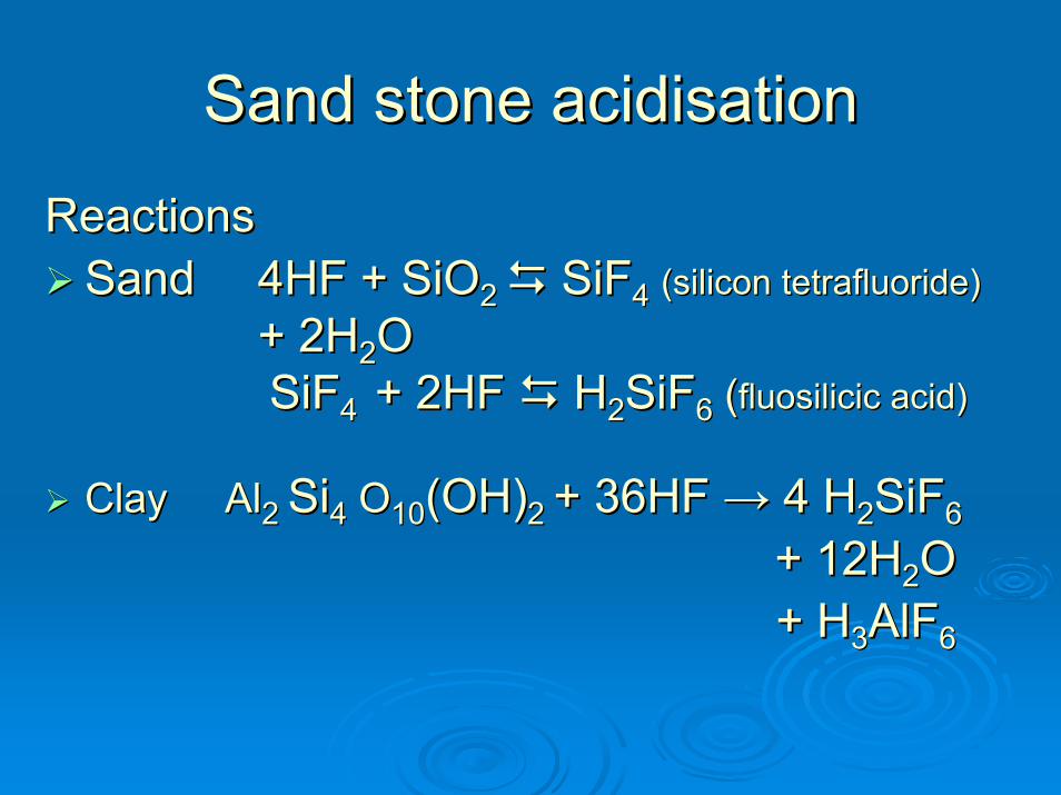
ReactionsReactionsSandSand 4HF + SiO4HF + SiO2 2 SiFSiF44 (silicon (silicon tetrafluoridetetrafluoride))
+ 2H+ 2H22OOSiFSiF4 4 + 2HF + 2HF HH22SiFSiF66 ((fluosilicicfluosilicic acid)acid)
Clay AlClay Al2 2 SiSi44 OO1010(OH)(OH)2 2 + 36+ 36HF HF →→ 4 4 HH22SiFSiF66
+ 12H+ 12H22OO+ + HH33AlFAlF66
Sand stone acidisationSand stone acidisation
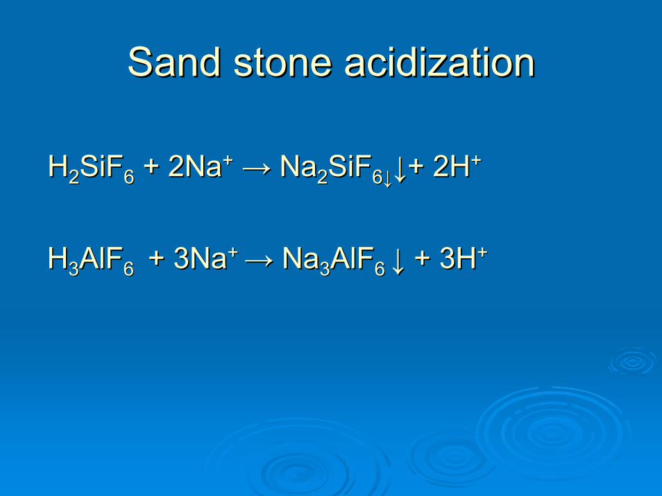
HH22SiFSiF66 + 2Na+ 2Na++ →→ NaNa22SiFSiF66↓↓↓↓+ 2H+ 2H++
HH33AlFAlF6 6 + 3Na+ 3Na+ + →→ NaNa33AlFAlF6 6 ↓↓ + 3H+ 3H++
Sand stone acidizationSand stone acidization

Hydrofluoric acid (HF) Hydrofluoric acid (HF) treatmenttreatment
OVERFLUSH
SURFACTANT
HF ACID
SURFACTANT
++
NaCl(3) (2) (1)
KCl
SURFACTANT
FORMATIONWATER+
Sand packPerforated CasingPerforated CementLiner
AcidizationAcidization steps in generalsteps in general
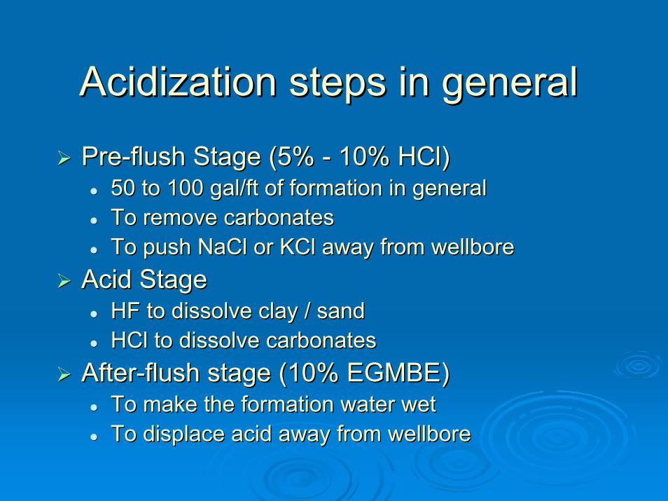
PrePre--flush Stage (5% flush Stage (5% -- 10% 10% HClHCl) ) 50 to 100 gal/ft of formation in general50 to 100 gal/ft of formation in generalTo remove carbonatesTo remove carbonatesTo push To push NaClNaCl or or KClKCl away from away from wellborewellbore
Acid StageAcid StageHF to dissolve clay / sandHF to dissolve clay / sandHClHCl to dissolve carbonatesto dissolve carbonates
AfterAfter--flush stage (10% EGMBE)flush stage (10% EGMBE)To make the formation water wetTo make the formation water wetTo displace acid away from To displace acid away from wellborewellbore

Acid additivesAcid additives
Corrosion InhibitorCorrosion InhibitorSurfactantSurfactantNonNon--EmulsifierEmulsifierAntiAnti--sludge Agentsludge AgentIron ControllerIron ControllerMutual SolventMutual SolventFriction ReducerFriction ReducerClay StabilizerClay StabilizerDiverting AgentDiverting Agent
Corrosion InhibitorCorrosion Inhibitor
Factors Affecting Corrosion During an Factors Affecting Corrosion During an Acid TreatmentAcid Treatment
TemperatureTemperatureContact TimeContact TimeAcid ConcentrationAcid ConcentrationMetal TypeMetal TypeCorrosion Inhibitor UsedCorrosion Inhibitor Used
SurfactantSurfactantCan act to :Can act to :
Change surface and interfacial tensionsChange surface and interfacial tensionsDisperse or flocculate clays and finesDisperse or flocculate clays and finesBreak, weaken emulsionsBreak, weaken emulsionsChange or maintain the wettability of reservoirChange or maintain the wettability of reservoirReduce acidReduce acid--induced sludginginduced sludgingCreate or break foamsCreate or break foamsPromote or prevent water blocksPromote or prevent water blocks

• Contains water soluble group (polymer)• Contains water soluble group (polymer)• Temperature sensitive• Temperature sensitive• More versatile & results in• More versatile & results in
•• Prevention of emulsion formation Prevention of emulsion formation •• Lowered surface tensionLowered surface tension•• Damage preventionDamage prevention
NonNon--EmulsifierEmulsifier
Anti Sludge agentAnti Sludge agent
““Sludge” is a precipitate formed from Sludge” is a precipitate formed from reaction of high strength acid with crude oil reaction of high strength acid with crude oil Methods of sludge preventionMethods of sludge prevention
Solvent (Solvent (XyleneXylene, Toluene) pre, Toluene) pre--flush to flush to minimize physical contactminimize physical contactUse of low strength acidUse of low strength acidAnionic surfactant to minimize precipitation of Anionic surfactant to minimize precipitation of colloidal suspensioncolloidal suspension

Iron ControllerIron ControllerMethods of Iron ControlMethods of Iron Control
Chelating (iron chemically bound) e.g. Acetic acid, Chelating (iron chemically bound) e.g. Acetic acid, Citric acidCitric acidSequestering (iron retained in solution) e.g. EDTA, Sequestering (iron retained in solution) e.g. EDTA, NTANTA
The Precipitation of IronThe Precipitation of IronFerrous Ion (Fe++) pH 7 or GreaterFerrous Ion (Fe++) pH 7 or GreaterFerric Ion (Fe+++) pH 2 to 3 Ferric Ion (Fe+++) pH 2 to 3
Sources of IronSources of IronScale: Iron oxide, Iron Sulfide, Iron CarbonateScale: Iron oxide, Iron Sulfide, Iron CarbonateFormation: Chlorite, Pyrite, SideriteFormation: Chlorite, Pyrite, Siderite
Mutual SolventMutual Solvent
Reasons for using a mutual solventReasons for using a mutual solventTo maintain a water wet formationTo maintain a water wet formation
To water wet insoluble formation finesTo water wet insoluble formation fines
To reduce water saturation near the To reduce water saturation near the wellborewellbore
To help reduce the absorption of To help reduce the absorption of surfactants and inhibitors on the formationsurfactants and inhibitors on the formation
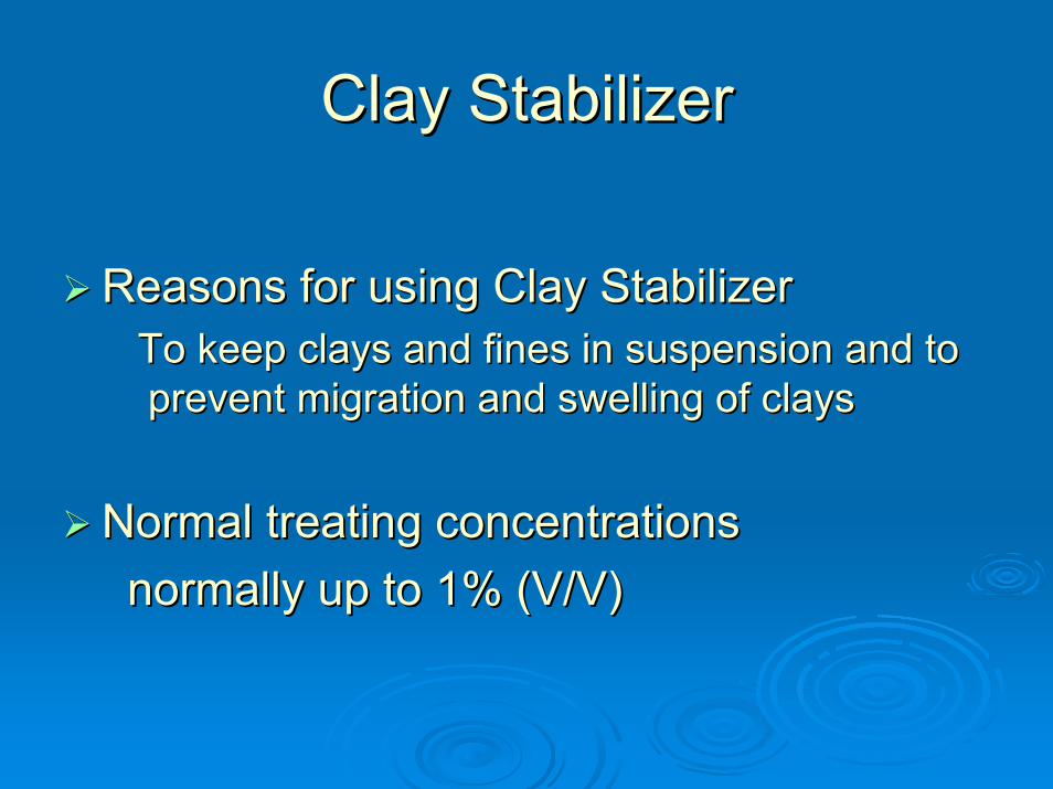
Clay StabilizerClay Stabilizer
Reasons for using Clay StabilizerReasons for using Clay StabilizerTo keep clays and fines in suspension and to To keep clays and fines in suspension and to prevent migration and swelling of claysprevent migration and swelling of clays
Normal treating concentrationsNormal treating concentrationsnormally up to 1% (V/V)normally up to 1% (V/V)

Diverting AgentDiverting AgentWhy Diverting Agent?Why Diverting Agent?To place the reactive fluid evenlyTo place the reactive fluid evenly
Among the pay zones in wells completed in Among the pay zones in wells completed in multiple layers with permeability contrastmultiple layers with permeability contrastWells completed in single layer with very Wells completed in single layer with very long interval with heterogeneity within the long interval with heterogeneity within the layerlayerWells completed in single layer with Wells completed in single layer with different magnitude of damage within the different magnitude of damage within the layerlayer

DiversionDiversion TechniquesTechniquesMechanical diversion techniquesMechanical diversion techniques
Mechanical isolation of pay zones with packers Mechanical isolation of pay zones with packers Chemical diversion techniquesChemical diversion techniques
Ball sealers Ball sealers Particulate diversion Particulate diversion Foamed acid diversion Foamed acid diversion Viscous fluid diversionViscous fluid diversion
•• Self diverting acid (SDA) based on polymer/surfactantsSelf diverting acid (SDA) based on polymer/surfactants
•• Diversion with Emulsified acidDiversion with Emulsified acid
•• Diversion with viscous slugDiversion with viscous slug

Ball SealersBall sealers are rubber-coated balls that are designed to seat in the perforation
Reactive fluids carry the balls and place on the
perforation tunnel of high perm zone, blocks them,
diverts acid to other intervals.
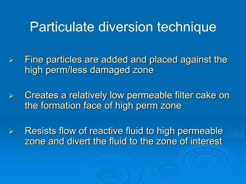
Particulate diversion technique
Fine particles are added and placed against the Fine particles are added and placed against the high perm/less damaged zone high perm/less damaged zone
Creates a relatively low permeable filter cake on Creates a relatively low permeable filter cake on the formation face of high perm zonethe formation face of high perm zone
Resists flow of reactive fluid to high permeable Resists flow of reactive fluid to high permeable zone and divert the fluid to the zone of interestzone and divert the fluid to the zone of interest

Particulate diversion techniqueParticulate diversion technique
Diverting agentDiverting agentss ConcentrationConcentration1.1. Oil soluble resin/ polymerOil soluble resin/ polymer 0.5 0.5 –– 5.0 gal/1000 gal5.0 gal/1000 gal
2.2. Benzoic acidBenzoic acid((not to use with HF)not to use with HF)
1.0 1.0 lbmlbm/ft/ft
3.3. Rock saltRock salt 0.50.5--2.0 2.0 lbm/flbm/f
4.4. wax beadswax beads 1.0 1.0 –– 2.0 2.0 lbmlbm/ft/ft
5.5. Naphthalene flakes Naphthalene flakes ((not to use in injection wells)not to use in injection wells)
0.25 0.25 –– 1.0 1.0 lbmlbm/ft/ft

Foamed diversion techniqueFoamed diversion techniqueFoams are stable mixture of liquids and Foams are stable mixture of liquids and gasesgases
In oil field, foam is produced byIn oil field, foam is produced by Injecting Nitrogen Injecting Nitrogen into water mixed with foamerinto water mixed with foamer
Nitrogen gas is trapped into the liquidNitrogen gas is trapped into the liquid,, occupies occupies 5050--60% of total volume of foam60% of total volume of foam
Foam restricts the flow of reactive fluid to high Foam restricts the flow of reactive fluid to high perm layer and diverts the fluid to low perm layerperm layer and diverts the fluid to low perm layer

Viscous fluid diversion techniqueViscous fluid diversion technique
Acid modified with polymer/surfactantAcid modified with polymer/surfactant
Preferably enters into the high perm zone and Preferably enters into the high perm zone and increases the viscosity inincreases the viscosity in--situ during acid situ during acid spending processspending process
Diverts remaining acid to the low perm or more Diverts remaining acid to the low perm or more damaged zone at elevated pressure.damaged zone at elevated pressure.
SelfSelf--diverting diverting Acid(SDAAcid(SDA) system) system

Acid diversion process

Flow Back
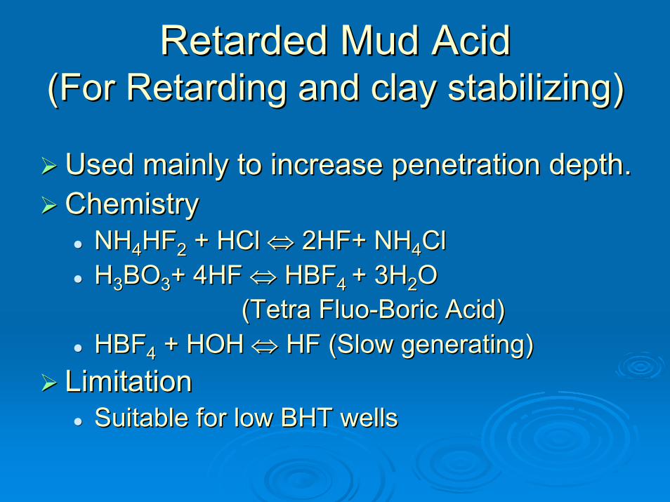
Retarded Mud AcidRetarded Mud Acid(For Retarding and clay stabilizing)(For Retarding and clay stabilizing)
Used mainly to increase penetration depth.Used mainly to increase penetration depth.Chemistry Chemistry
NHNH44HFHF22 + HCl + HCl ⇔⇔ 2HF+ NH2HF+ NH44ClClHH33BOBO33+ 4HF + 4HF ⇔⇔ HBFHBF4 4 + 3H+ 3H22O O
(Tetra (Tetra FluoFluo--Boric Acid) Boric Acid) HBFHBF44 + HOH + HOH ⇔⇔ HF (Slow generating)HF (Slow generating)
LimitationLimitationSuitable for low BHT wellsSuitable for low BHT wells
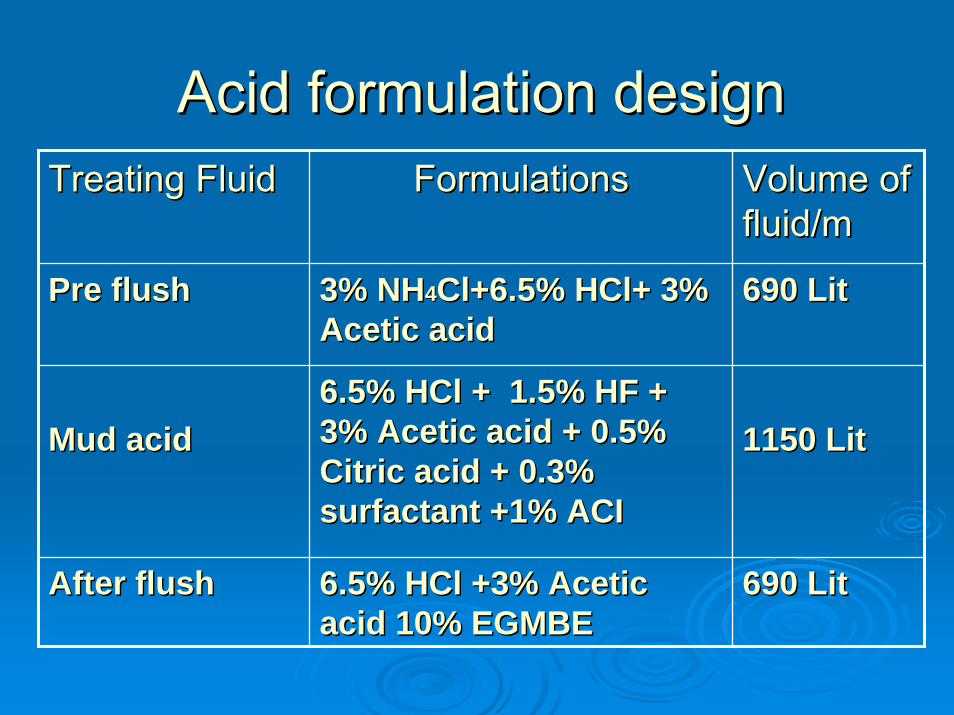
Acid formulation design Acid formulation design Treating FluidTreating Fluid FormulationsFormulations
Pre flushPre flush 3% NH3% NH44Cl+6.5% HCl+ 3% Cl+6.5% HCl+ 3% Acetic acidAcetic acid
6.5% HCl + 1.5% HF + 6.5% HCl + 1.5% HF + 3% Acetic acid + 0.5% 3% Acetic acid + 0.5% Citric acid + 0.3% Citric acid + 0.3% surfactant +1% ACIsurfactant +1% ACI
6.5% HCl +3% Acetic 6.5% HCl +3% Acetic acid 10% EGMBEacid 10% EGMBE
Mud acidMud acid
After flushAfter flush
Volume of Volume of fluid/mfluid/m
690 Lit690 Lit
1150 Lit1150 Lit
690 Lit690 Lit
HYDRAULIC FRACTURING
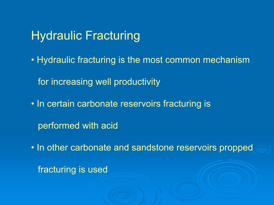
Hydraulic Fracturing
• Hydraulic fracturing is the most common mechanism
for increasing well productivity
• In certain carbonate reservoirs fracturing is
performed with acid
• In other carbonate and sandstone reservoirs propped
fracturing is used
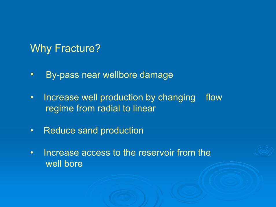
Why Fracture?
• By-pass near wellbore damage
• Increase well production by changing flow regime from radial to linear
• Reduce sand production
• Increase access to the reservoir from the well bore
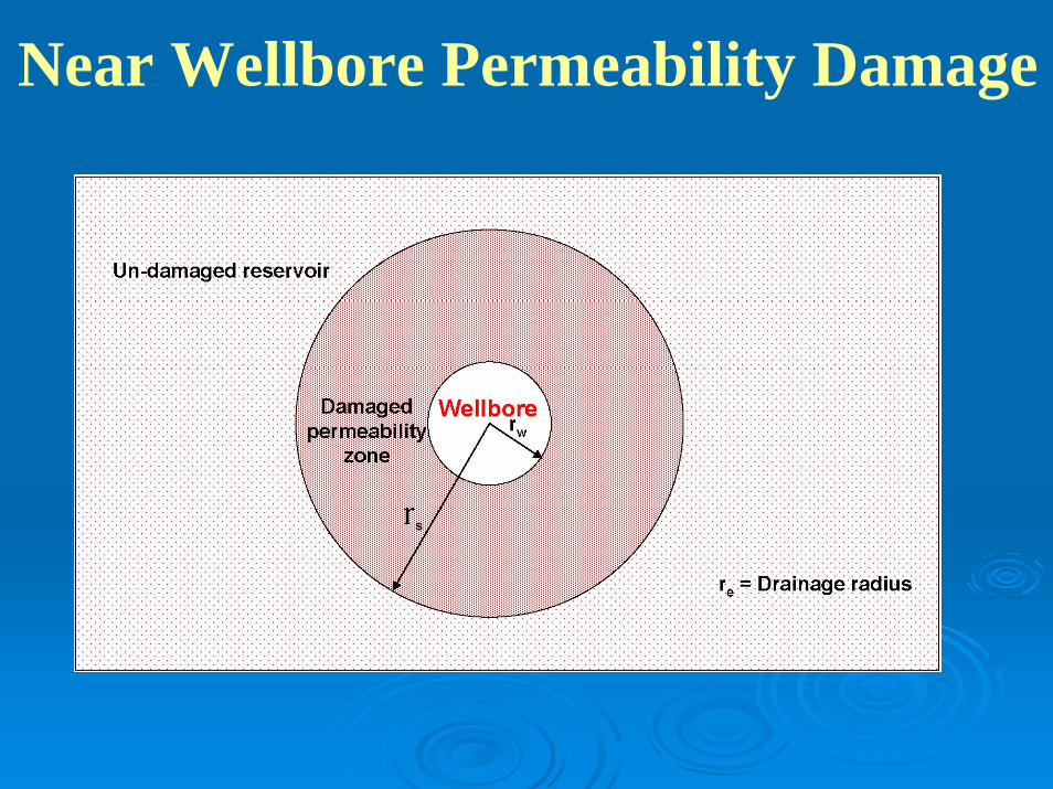
Near Wellbore Permeability Damage
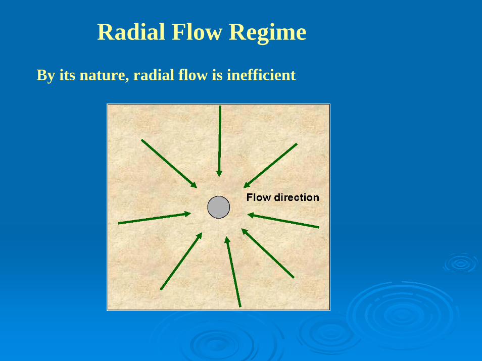
Radial Flow Regime
By its nature, radial flow is inefficient

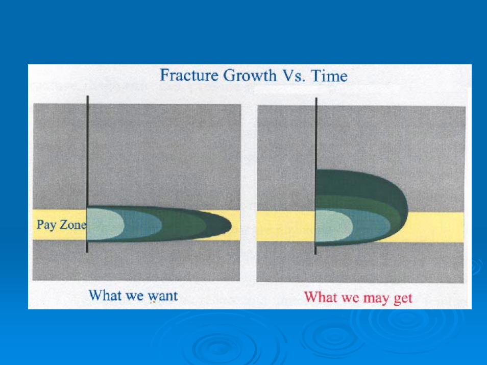
Effect of Hydraulic Fracture on Flow Regime
If properly created, hydraulic fractures canchange flow regime from radial to linear
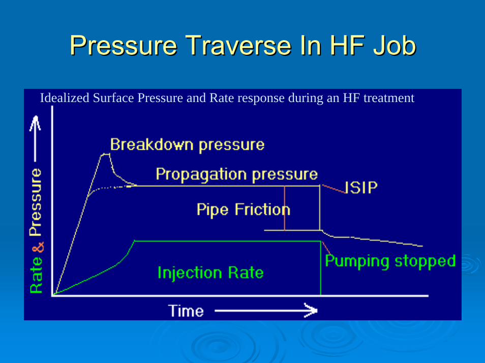
Pressure Traverse In HF JobPressure Traverse In HF Job
Idealized Surface Pressure and Rate response during an HF treatment


Vertical fracture usually occurs at a depth below 6000 ft.
Fracture OrientationFracture Orientation
Fracturing Gradient = bottom-hole frac-pressure/ Depth
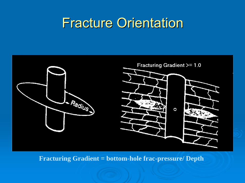
Horizontal fracture usually occurs at a depth above 6000 ft.
Fracture OrientationFracture Orientation
Fracturing Gradient = bottom-hole frac-pressure/ Depth
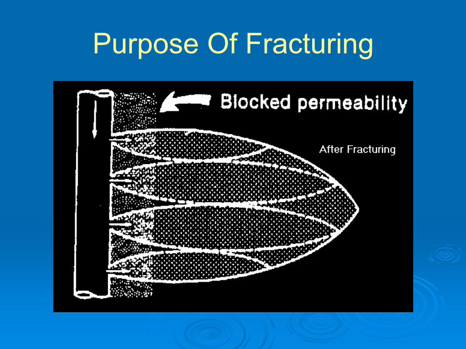
Purpose Of FracturingTo increase productivity by penetrating blocked permeability near the well bore.
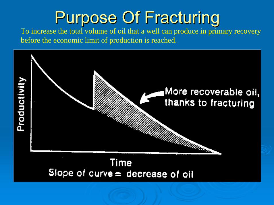
Purpose Of FracturingPurpose Of FracturingTo increase the total volume of oil that a well can produce in primary recovery before the economic limit of production is reached.
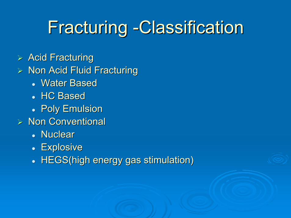
Fracturing Fracturing --Classification Classification Acid FracturingAcid FracturingNon Acid Fluid FracturingNon Acid Fluid Fracturing
Water BasedWater BasedHC BasedHC BasedPoly EmulsionPoly Emulsion
Non ConventionalNon ConventionalNuclearNuclearExplosiveExplosiveHEGS(high energy gas stimulation)HEGS(high energy gas stimulation)

Good Candidates For FracturingGood Candidates For Fracturing
Sufficient Recoverable ReservesSufficient Recoverable ReservesSufficient Reservoir PressureSufficient Reservoir PressureLow Permeability (Less Than 10 Low Permeability (Less Than 10 mDmD))O/W And O/G contacts Not Very CloseO/W And O/G contacts Not Very CloseGood CementationGood Cementation

General Criteria For Well SelectionGeneral Criteria For Well Selection
State of depletion of producing formationState of depletion of producing formationFormation composition & consolidationFormation composition & consolidationFormation permeabilityFormation permeabilityFormation thicknessFormation thicknessIsolation of the zone to be treatedIsolation of the zone to be treatedCondition of well equipmentCondition of well equipmentProduction history of the wellProduction history of the wellOffset production historyOffset production historyLocation of water, oilLocation of water, oil--water and gaswater and gas--oil contactsoil contacts

Frac Fluids Frac Fluids -- PropertiesProperties
Reservoir CompatiblityReservoir CompatiblityLow leak off rateLow leak off rateAbility to carry the propping agentAbility to carry the propping agentLow friction lossLow friction lossEasy removal from the formationEasy removal from the formationStability at reservoir conditionStability at reservoir conditionAvailabilityAvailabilitySafetySafetyCost economicsCost economics

Type Of Frac FluidsType Of Frac Fluids
Water baseWater baseOil baseOil baseAcid baseAcid baseFluid emulsionsFluid emulsionsFoamed fluidFoamed fluid

Characteristics Characteristics Of Of
Major Fluid SystemsMajor Fluid Systems
Water baseWater baseGelled water: medium viscosity, low frictionGelled water: medium viscosity, low frictionCross linked water gel: high viscosity, high Cross linked water gel: high viscosity, high proppantproppant carrying capacity, low friction loss carrying capacity, low friction loss (with the help of delayed cross linker)(with the help of delayed cross linker)

Oil baseOil baseCompatible with reservoir, high viscosity, high Compatible with reservoir, high viscosity, high friction lossfriction loss
Emulsion baseEmulsion baseGood viscosity, low fluid loss, good clean upGood viscosity, low fluid loss, good clean up
Acid baseAcid baseLow viscosity, unstable at high temperature Low viscosity, unstable at high temperature

FRAC PROCEDURES / FRAC PROCEDURES / OPERATIONSOPERATIONS


Spearhead Spearhead Spearhead reduce breakdown pressure Spearhead reduce breakdown pressure
Typically 5 Typically 5 -- 10 bbl HCl acid ahead of pad10 bbl HCl acid ahead of padFormations can be difficult to breakdown, Formations can be difficult to breakdown, due to perforation damage, etc.due to perforation damage, etc.
Pump 50% into formation at matrix rates Pump 50% into formation at matrix rates Shut down 5 minutes Shut down 5 minutes Pick up rate and Frac the last 50% of acidPick up rate and Frac the last 50% of acidContinue with main FracContinue with main Frac

PAD PAD
Initiate fracture Initiate fracture Breakdown the perforationsBreakdown the perforationsDevelop width required for Develop width required for proppantproppant
like a wedge to initiate fracture like a wedge to initiate fracture Sometimes use extraSometimes use extra--viscous previscous pre--padspadsSometimes referred to as ‘clean fluid’Sometimes referred to as ‘clean fluid’

PAD PAD
Small pads may not develop sufficient Small pads may not develop sufficient width for width for proppantproppant, potentially causing , potentially causing screenscreen--outs outs Excessive pad may delay closure for a Excessive pad may delay closure for a significant period of time, allowing significant period of time, allowing proppantproppant convection out of zone.convection out of zone.
RATE RATE
Rate must exceed leakRate must exceed leak--off into the off into the formation in order to propagate the formation in order to propagate the fracfrac
Typically performed 15Typically performed 15--25 bbl/min25 bbl/min
In some cases, either higher or lower In some cases, either higher or lower rates are required.rates are required.

Proppant Schedule Proppant Schedule
Defines the Defines the proppantproppant addition rate into the addition rate into the slurryslurryTypically 1 Typically 1 -- 16 ppg16 ppg
e.g. 5 ppg means that 5 lb of e.g. 5 ppg means that 5 lb of proppantproppant is is added to 1.0 gallon clean fluid, for a total of added to 1.0 gallon clean fluid, for a total of 1.225 gallon slurry.1.225 gallon slurry.
Increase either in a ramp or increments of Increase either in a ramp or increments of 1 1 -- 2 ppg.2 ppg.
ProppantProppant Stages Stages
Immediately follow the padImmediately follow the padSlurry is ‘clean’ fracturing fluid mixed with Slurry is ‘clean’ fracturing fluid mixed with proppant proppant -- sometimes referred to as ‘dirty sometimes referred to as ‘dirty fluid’fluid’Continue to generate length and width Continue to generate length and width Start proppant at 1 Start proppant at 1 --3 ppg3 ppgSlowly increase proppant concentrations.Slowly increase proppant concentrations.
ProppantProppant Stages Stages
Perforation and near Perforation and near -- wellbore may not wellbore may not accept higher concentrations of proppant accept higher concentrations of proppant early in the treatment ( i.e if wedge isn’t early in the treatment ( i.e if wedge isn’t large enough)large enough)Erode the perforation and the formation Erode the perforation and the formation

Flush Flush
Immediately follows the Immediately follows the proppantproppant stages stages Pump clean (nonPump clean (non--sandsand--laden) fluid to laden) fluid to displace the displace the proppantproppant to within a short to within a short distance of the perforation and remove it distance of the perforation and remove it from the wellborefrom the wellboreUse low friction, economical fluidUse low friction, economical fluidOften friction reduced based fluid is used.Often friction reduced based fluid is used.
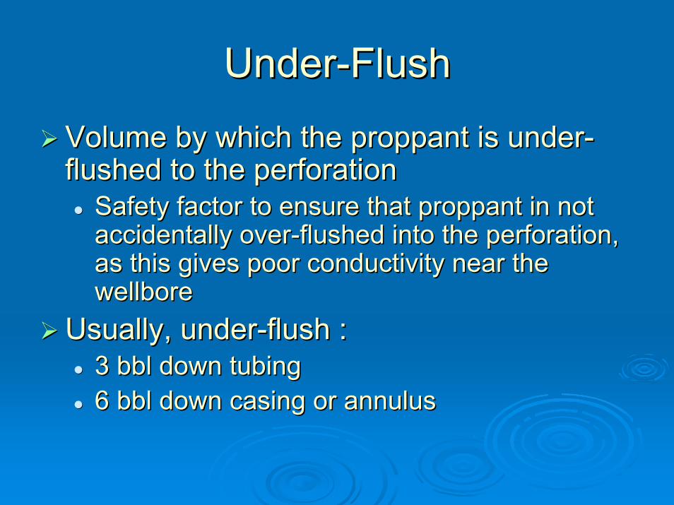
UnderUnder--Flush Flush
Volume by which the Volume by which the proppantproppant is underis under--flushed to the perforationflushed to the perforation
Safety factor to ensure that Safety factor to ensure that proppantproppant in not in not accidentally overaccidentally over--flushed into the perforation, flushed into the perforation, as this gives poor conductivity near the as this gives poor conductivity near the wellborewellbore
Usually, underUsually, under--flush :flush :3 bbl down tubing 3 bbl down tubing 6 bbl down casing or annulus 6 bbl down casing or annulus

Real Time MonitoringReal Time Monitoring

Fracture InitiationFracture Initiation

Proppant InitiationProppant Initiation

Ideal Frac CompletionIdeal Frac Completion
Pad Created Fracture Vol. = Proppant Laden Fracture Vol.

WATER CONTROLWATER CONTROL
WHY & HOWWHY & HOW

Why Water ControlWhy Water Control
For every barrel oil we produce 3 barrel water.For every barrel oil we produce 3 barrel water.For a typical well with 80% water cut the we For a typical well with 80% water cut the we spend $4 /bbl for water spend $4 /bbl for water
Reasons of additional cost Reasons of additional cost Lift and separationLift and separationTreatment & disposalTreatment & disposalCorrosion & ScalingCorrosion & ScalingFormation damage, loss of productivityFormation damage, loss of productivity
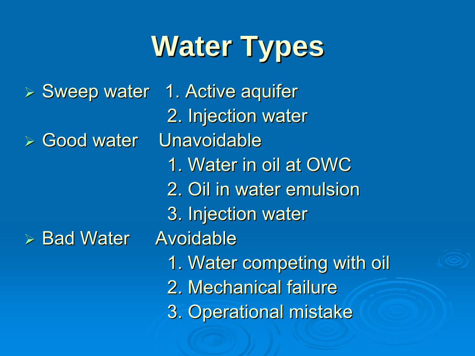
Water TypesWater TypesSweep water 1. Active aquifer Sweep water 1. Active aquifer
2. Injection water2. Injection waterGood water Unavoidable Good water Unavoidable
1. Water in oil at OWC 1. Water in oil at OWC 2. Oil in water emulsion2. Oil in water emulsion3. Injection water 3. Injection water
Bad Water Avoidable Bad Water Avoidable 1. Water competing with oil 1. Water competing with oil 2. Mechanical failure 2. Mechanical failure 3. Operational mistake3. Operational mistake
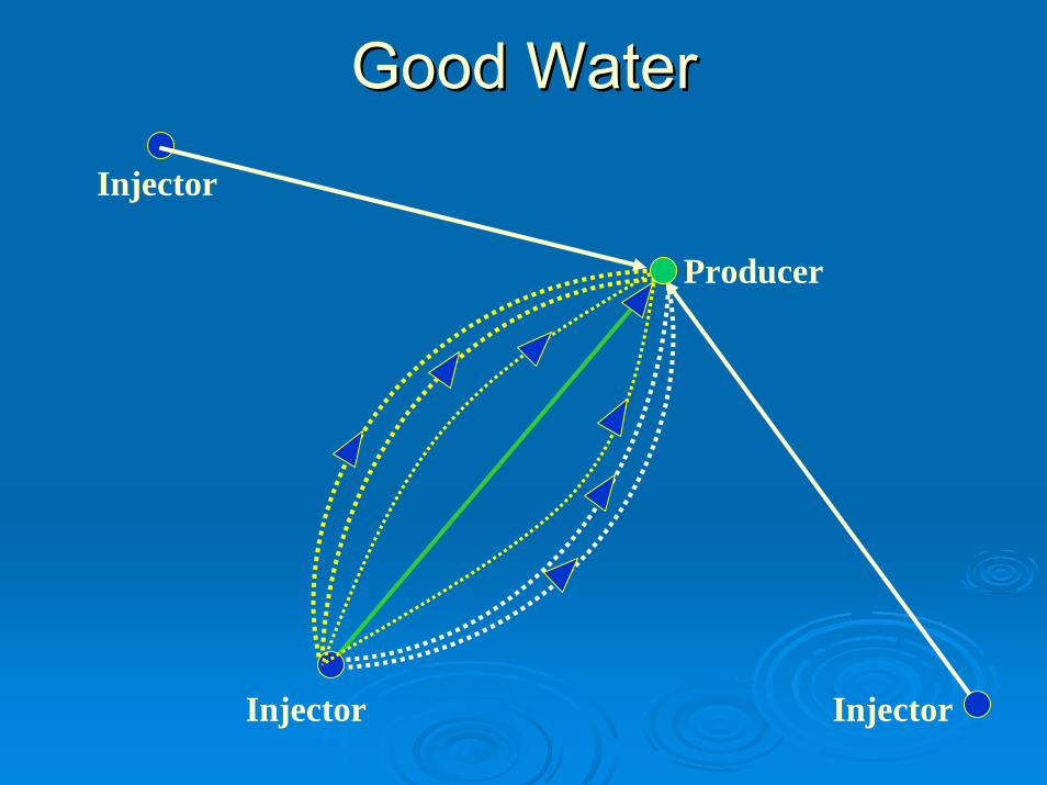
Good Water Good Water
Injector
Producer
Injector
Injector

Bad Bad WaterWater
Coning
Crossflow
BreakthroughRise of OWC
FractureChanneling
Casing Leak
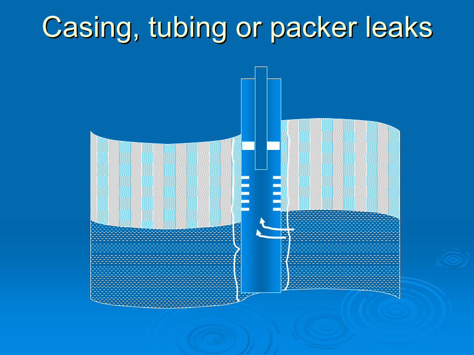
Casing, tubing or packer leaks Casing, tubing or packer leaks
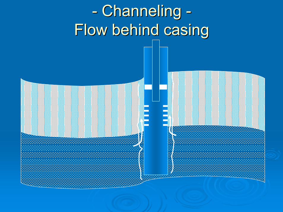
-- Channeling Channeling --Flow behind casing Flow behind casing
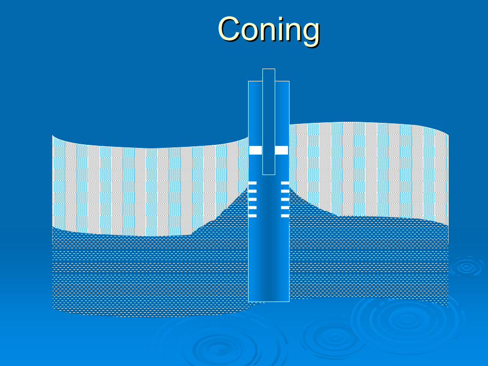
Coning Coning
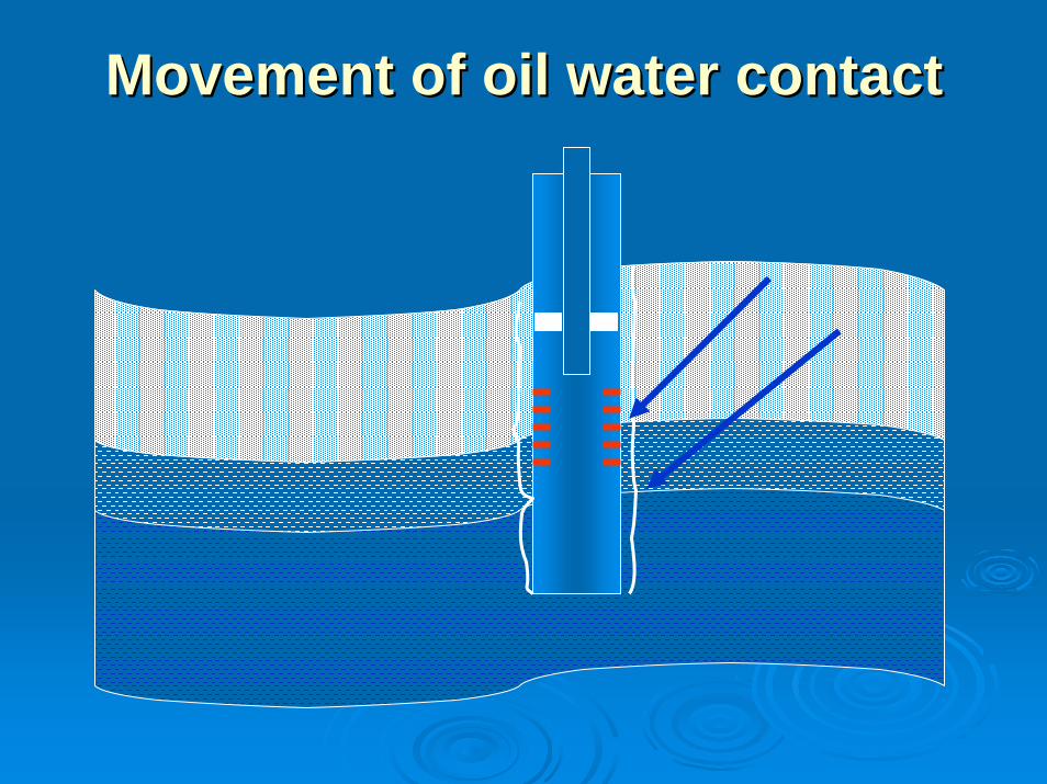
Movement of oil water contact Movement of oil water contact
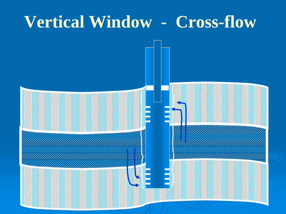
Vertical Window - Cross-flow
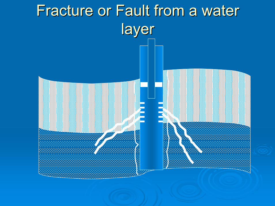
Fracture or Fault from a water Fracture or Fault from a water layer layer

Injection water breakthrough Injection water breakthrough
InjectorProducer
Key to water control is proper diagnosis Key to water control is proper diagnosis
Screen wells suitable for water controlScreen wells suitable for water controlDetermine the type of problemDetermine the type of problemFind the correct water entry point Find the correct water entry point Find the best control systemFind the best control systemFind suitable placement methodFind suitable placement method
Well Diagnostics & Candidate selectionWell Diagnostics & Candidate selection
TOOLS & TECHNIQUESTOOLS & TECHNIQUES
Well History :Well History :Drilling historyDrilling historyWell geometryWell geometryMud loss historyMud loss historyFiltration lossFiltration loss
Well Diagnostics & Candidate electionWell Diagnostics & Candidate election

TOOLS & TECHNIQUESTOOLS & TECHNIQUES
Geological dataGeological dataReservoir dataReservoir dataWater analysis dataWater analysis dataOil analysis dataOil analysis data
Well Diagnostics & Candidate electionWell Diagnostics & Candidate election

TOOLS & TECHNIQUESTOOLS & TECHNIQUESProduction historyProduction history
Recovery plotRecovery plotProduction history plotProduction history plotDecline curveDecline curveDiagnostic plotDiagnostic plot
Well Diagnostics & Candidate electionWell Diagnostics & Candidate election

Well LogsWell LogsOpen hole logsOpen hole logsCased hole logsCased hole logsProduction logsProduction logsUSIT USIT FMIFMI
TOOLS & TECHNIQUESTOOLS & TECHNIQUES
Well Diagnostics & Candidate electionWell Diagnostics & Candidate election

Water Control SolutionsWater Control Solutions
MechanicalMechanical
PhysicalPhysical
ChemicalChemical

Mechanical Solutions & Well TechniquesMechanical Solutions & Well TechniquesPackersPackersBridge PlugsBridge PlugsCasing PatchesCasing PatchesInfill DrillingInfill DrillingSide Tracking Side Tracking Pattern Flow ControlPattern Flow ControlHorizontal Horizontal Multilateral Multilateral
Water Control MaterialsWater Control Materials

Physical Plugging AgentsPhysical Plugging AgentsConventional Cement SqueezeConventional Cement SqueezeUltra Fine CementUltra Fine CementFoamFoam--cementcementParticulates Particulates Sand PlugSand Plug

Conventional Cement SqueezeConventional Cement SqueezeOften performs well as a blocking agentOften performs well as a blocking agentGood solution for large casing holeGood solution for large casing holeLong lifeLong lifeNear wellbore applicationNear wellbore applicationPoor penetrationPoor penetrationProvide Mechanical strength to Polymer Provide Mechanical strength to Polymer
gelgelEconomicalEconomical
UltraUltra--fine Cement (fine Cement (Size Size -- < 10 micron)< 10 micron)Better penetrability than conventional Better penetrability than conventional cementcement
Small size casing holeSmall size casing holeMicroMicro--channelschannelsCan be mixed with ultra fine silicaCan be mixed with ultra fine silicaThermal stabilityThermal stabilityExpensiveExpensive
Hydrocarbon based ultraHydrocarbon based ultra--fine Cement fine Cement
Reacts slowly upon contact with waterReacts slowly upon contact with waterModerate penetration depthModerate penetration depthCan be used in conjunction with polymer Can be used in conjunction with polymer gelgel

Foam Cement Foam Cement
Reduced weight Reduced weight Moderate penetration depthModerate penetration depthCan be used in conjunction with polymer gelCan be used in conjunction with polymer gel
Particulates Particulates
Clay gelsClay gelsCarbonatesCarbonatesVarious Loss control materials Various Loss control materials
To be used in combination with other To be used in combination with other chemical system,chemical system,

Sand plugSand plug
RigRig--less alternative to cement plugless alternative to cement plugLow costLow costTo be applied with binderTo be applied with binderSupporting agent to Supporting agent to low strength polymer gellow strength polymer gelInexpensiveInexpensive

Monomer SystemsMonomer Systems
Water thin Water thin gellantgellantThermal & catalytic activationThermal & catalytic activationInIn--situ polymerizationsitu polymerizationDesignable placement timeDesignable placement timeMatrix treatment in low permeable reservoirMatrix treatment in low permeable reservoirHigh volume application possible High volume application possible Applicable Applicable uptoupto 140 140 00CCTotal to partial sealantTotal to partial sealantEasy to mixEasy to mix
CrossCross--linked Polymer Systemslinked Polymer Systems
Mainly Mainly acrylamideacrylamide terter--polymer polymer Organic or Inorganic crossOrganic or Inorganic cross--linkerlinkerVariable concentrationVariable concentrationLow to very high viscosityLow to very high viscosityDesignable placement timeDesignable placement timeApplicable in sand stone & carbonateApplicable in sand stone & carbonateLarge volume application possible Large volume application possible Applicable Applicable uptoupto 140 140 00CCTotal sealantTotal sealant

CrossCross--linked Polymer Systemslinked Polymer Systems
Application Application Bottom water shutoffBottom water shutoffConingConingChannel from InjectorChannel from InjectorCasing leakCasing leakFracture into injector/aquifer Fracture into injector/aquifer Plugging operation/zone abandonmentPlugging operation/zone abandonmentGas shutoffGas shutoff

Relative permeability Modifier (RPM)Relative permeability Modifier (RPM)
XanthamXantham coco--polymer (XC)polymer (XC)Inorganic crossInorganic cross--linkerlinkerLow to very high viscosityLow to very high viscosityShear thinningShear thinningApplicable in sand stone Applicable in sand stone Large volume application possible Large volume application possible Applicable Applicable uptoupto 100 100 00CCDesignable gel strengthDesignable gel strength

Relative permeability Modifier (RPM)Relative permeability Modifier (RPM)
Permeability of oil/water Permeability of oil/water uptoupto 1010Bull head treatment possibleBull head treatment possibleNeeds mechanical supportNeeds mechanical supportLow costLow costApplicable in 3Applicable in 3--D conning & D conning & unpredictable watered out zoneunpredictable watered out zone
ResinsResins
2 or 3 component system2 or 3 component systemLow viscosityLow viscosityPermanent solutionPermanent solutionIrretrievable Irretrievable Relatively higher costRelatively higher costApplicable for channel repair and casing Applicable for channel repair and casing leakleak

Placement StrategiesPlacement Strategies
Coning
Crossflow
BreakthroughRise of OWC
FractureChanneling
Casing Leak

SAND CONTROLSAND CONTROL

Geological SandsGeological Sands
Marine deposited sands:Marine deposited sands:Cemented with calcareous or siliceous Cemented with calcareous or siliceous material.material.Well consolidated.Well consolidated.
Erosion deposited sandsErosion deposited sandsCemented with soft clay/silt.Cemented with soft clay/silt.Partly consolidated.Partly consolidated.Unconsolidated.Unconsolidated.
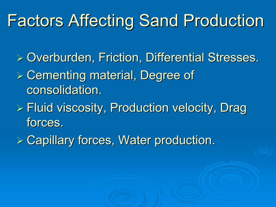
Overburden, Friction, Differential Stresses.Overburden, Friction, Differential Stresses.Cementing material, Degree of Cementing material, Degree of consolidation.consolidation.Fluid viscosity, Production velocity, Drag Fluid viscosity, Production velocity, Drag forces.forces.Capillary forces, Water production.Capillary forces, Water production.
Factors Affecting Sand ProductionFactors Affecting Sand Production

•OVERBURDEN
•CEMENTING
•CAPILLARY
•DRAG

Sand ControlSand Control
DefinitionDefinitionStop sand movement & maintain maximum Stop sand movement & maintain maximum production.production.
Success measures:Success measures:Stop sand movement.Stop sand movement.Maintain maximum productionMaintain maximum productionPay out cost.Pay out cost.
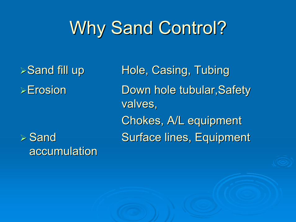
Why Sand Control?Why Sand Control?
Sand fill upSand fill up Hole, Casing, TubingHole, Casing, Tubing
ErosionErosion Down hole tubular,Safety Down hole tubular,Safety valves,valves,Chokes, A/L equipmentChokes, A/L equipment
Sand Sand accumulationaccumulation
Surface lines, EquipmentSurface lines, Equipment

Abrasive wearAbrasive wear Surface control, Valves, Surface control, Valves, PipesPipes
Buckling of casingBuckling of casingHandling & disposalHandling & disposal
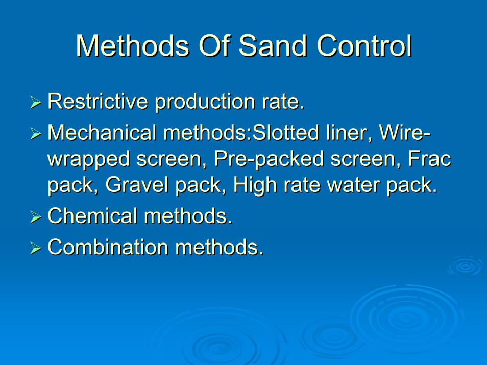
Methods Of Sand ControlMethods Of Sand Control
Restrictive production rate.Restrictive production rate.Mechanical methods:Slotted liner, WireMechanical methods:Slotted liner, Wire--wrapped screen, Prewrapped screen, Pre--packed screen, Frac packed screen, Frac pack, Gravel pack, High rate water pack.pack, Gravel pack, High rate water pack.Chemical methods.Chemical methods.Combination methods.Combination methods.

Resin coated sand is pumped through perforations, filling voids and re-stressing formation. It will harden in this shapes form a permeable mass.
STEP: 1
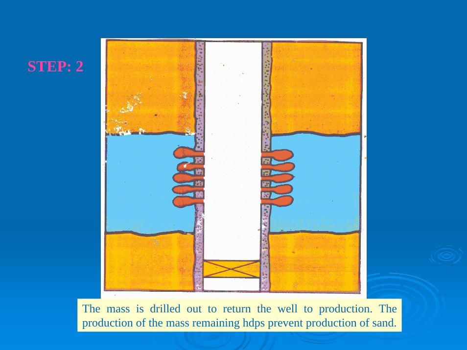
The mass is drilled out to return the well to production. The production of the mass remaining hdps prevent production of sand.
STEP: 2

Gravel PackGravel Pack
Consists of sized Consists of sized particles placed particles placed in the annular in the annular space between an space between an unconsolidated unconsolidated formation and a formation and a centralized centralized screen.screen.open or cased open or cased hole.hole.
Sand Gravel Screen
OIL GAS
Laboratory AnalysisLaboratory Analysis
Sand sampling:Sand sampling:Rubber sleeve cores.Rubber sleeve cores.Conventional cores.Conventional cores.SideSide--wall cores.wall cores.Bailed samples.Bailed samples.Produced sand.Produced sand.
Sieve analysisSieve analysisClay content.Clay content.

Sieve AnalysisSieve Analysis
U.S. MESH
CU
MU
LA
TIV
E %
OF
SAM
PLE
50 % SIZE
10 % SIZE

ROUNDNESS
SPH
ER
ICIT
Y
KRUMBEIN & SLOSS CHART

Well PreparationWell Preparation
Perforation:Perforation:Type: Over balance, TCP, EOBType: Over balance, TCP, EOBDensity: 12 SPFDensity: 12 SPFEntry hole Entry hole diadia.: 0.75”.: 0.75”
Perforation Cleaning:Perforation Cleaning:Back surgingBack surgingPerforation washingPerforation washing

TYPICAL TYPICAL GRAVEL GRAVEL
PACK PACK SYSTEMSSYSTEMS
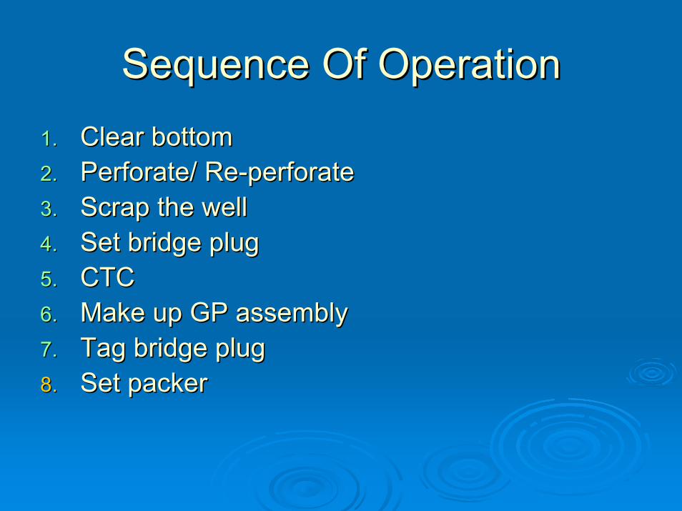
Sequence Of OperationSequence Of Operation1.1. Clear bottomClear bottom2.2. Perforate/ RePerforate/ Re--perforateperforate3.3. Scrap the wellScrap the well4.4. Set bridge plugSet bridge plug5.5. CTCCTC6.6. Make up GP assemblyMake up GP assembly7.7. Tag bridge plugTag bridge plug8.8. Set packerSet packer
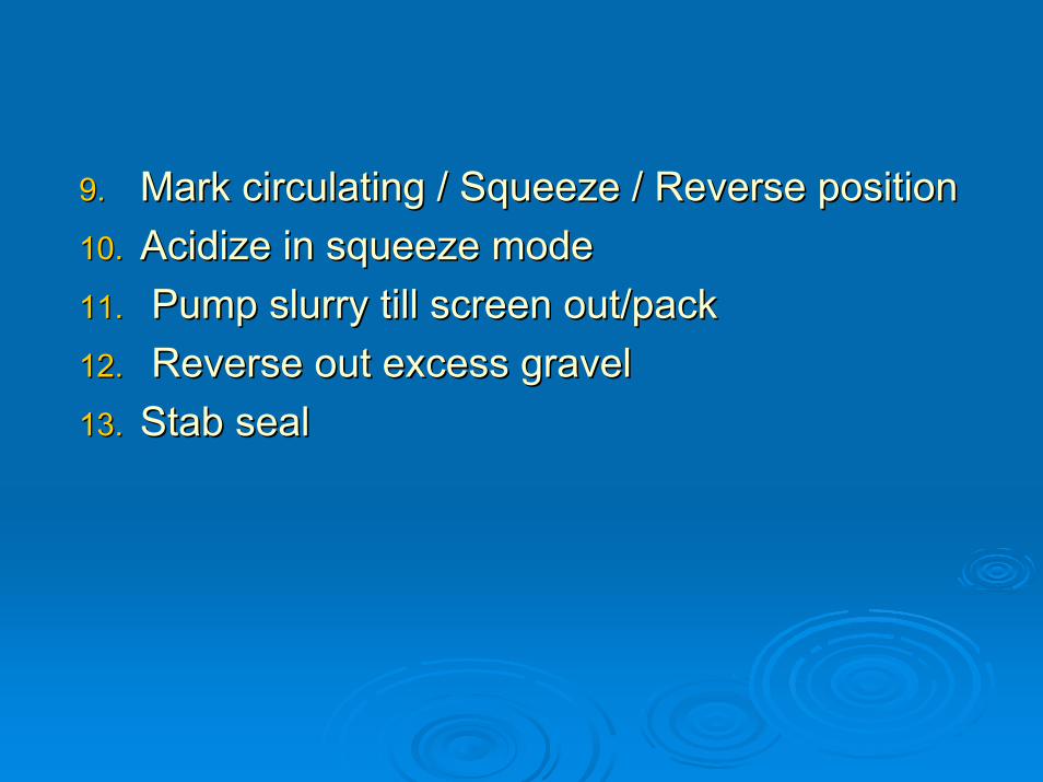
9.9. Mark circulating / Squeeze / Reverse positionMark circulating / Squeeze / Reverse position10.10. AcidizeAcidize in squeeze modein squeeze mode11.11. Pump slurry till screen out/packPump slurry till screen out/pack12.12. Reverse out excess gravelReverse out excess gravel13.13. Stab sealStab seal

BLANK PIPES
SCREEN
LOWER TELL TAIL
LANDING NIPPLE
CROSS OVER TOOL
POLISHED BORE RECEPTACLE WITH “O” RING