welder training program - british columbia · pdf fileof bc welder training program learning...
TRANSCRIPT

Welder Training Programlevel C
P4: Shielded metal arc Welding i (SmaW i)Practical Competencies

Acknowledgements & Copyright Permission
The Industry Training Authority of British Columbia would like to acknowledge the Welding Articulation Committee and Open School BC, a division of the Queen’s Printer as well as the following individuals and organizations for their contributions in updating the Welder Training modules:
Welding Articulation Committee (WAC) Members and Consultants—“The Working Group”Jim Carson (Welding Articulation Committee Chair), University of the Fraser Valley (writer and senior reviewer)
Peter Haigh (Welding Curriculum Review Committee Chair), Northwest Community College (writer and senior reviewer)
Sheldon Frank, University of the Fraser Valley (writer and reviewer)
Greg Burkett, Okanagan College (writer and reviewer)
Randy Zimmerman (writer and reviewer)
John H.P. Little (reviewer)
Resource Training Organization (RTO)
BC Council on Admissions and Transfer (BCCAT)
The Queen’s PrinterThe Queen’s Printer, through its Open School BC unit, provided project management and design expertise in updating the Welder Training Level C print materials.
Open School BCSolvig Norman, Senior Project ManagerEleanor Liddy, Director/AdvisorDennis Evans, Production Technician (print layout, graphics & photographs)Christine Ramkeesoon, Graphics Media CoordinatorKeith Learmonth, EditorMargaret Kernaghan, Graphic Artist
Publishing ServicesSherry Brown, Director of Publishing Services
Intellectual Property Program Ilona Ugro, Copyright Officer, Ministry of Citizens’ Services, Province of British Columbia
Copyright Permission
The following suppliers have kindly provided copyright permission for selected product images:
Acklands-Grainger Inc.The Crosby GroupJ. Walter Company Ltd.Lincoln Electric CompanyNDT Systems, Inc.Praxair, Inc.Thermadyne Canada (Victor Equipment)The Miller Electric Mfg. Co.ESAB Welding & Cutting Products
Photo of welder walks the high steel at a construction site, Kenneth V. Pilon, copyright 2010. Used under license from Shutterstock.com
A special thank you to Lou Bonin and Jim Stratford at Camosun College (Welding department) for assisting us with additional photographs. An additional thank you to Richard Smith from England, for allowing us to use photographs of hydrogen bubbles.

ForewordThe Industry Training Authority (ITA) is pleased to release this major update of learning resources to support the delivery of the BC Welder Program. It was made possible by the dedicated efforts of the Welding Articulation Committee of BC (WAC).
The WAC is a working group of welding instructors from institutions across the province and is one of the key stakeholder groups that support and strengthen industry training in BC. It was the driving force behind the update of the welding learning modules supplying the specialized expertise required to incorporate technological, procedural and industry-driven changes. The WAC plays an important role in the province’s post-secondary public institutions as discipline specialists that share information and engage in discussions of curriculum matters, particularly those affecting student mobility.
ITA would also like to acknowledge the Resource Training Organization (RTO) which provides direction for improving industry training in the resource sector and which led consultation on changes related to the BC welder training program.
We are grateful to WAC and RTO for their contributions to the ongoing development of BC Welder Training Program Learning Resources (materials whose ownership and copyright are maintained by the Province of British Columbia through ITA).
Industry Training AuthorityAugust 2010
DisclaimerThe materials in these modules are for use by students and instructional staff and have been compiled from sources believed to be reliable and to represent best current opinions on these subjects. These manuals are intended to serve as a starting point for good practises and may not specify all minimum legal standards. No warranty, guarantee or representation is made by the British Columbia Welding Articulation Committee, the British Columbia Industry Training Authority or the Queen’s Printer of British Columbia as to the accuracy or sufficiency of the information contained in these publications. These manuals are intended to provide basic guidelines for welding trade practises. Do not assume, therefore, that all necessary warnings and safety precautionary measures are contained in this module and that other or additional measures may not be required.

4 WelDer TrAInInG PrOGrAM — level C
P4: Shielded Metal Arc Welding I (SMAW I) Practical Competencies
Table of Contents
Practical Competency P4-11: Bead welds in the flat position on low-carbon steel plate 7
P4-11 Learning Task 1: Strike an arc on low-carbon steel plate . . . . . . . . . . . . . . . 11
WPS P4-11-1A: Strike an arc using the scratch method . . . . . . . . . . . . . . . . 14
WPS P4-11-1B: Strike an arc using the tap method . . . . . . . . . . . . . . . . . . 16
WPS P4-11-1C: Strike an arc with an E4918 (E7018) electrode using the scratch and tap methods . . . . . . . . . . . . . . . . . . . . . . . . . . . . . . . . . . . 18
P4-11 Learning Task 2: Bead welds in the flat position on low-carbon steel plate. . . . . . 19
WPS P4-11-2A: Stringer bead welds in the flat position . . . . . . . . . . . . . . . . 20
WPS P4-11-2B: Weave bead welds in the flat position . . . . . . . . . . . . . . . . . 22
Practical Competency P4-12: Fillet welds on low-carbon steel plate 25
P4-12 Learning Task 1: Fillet welds in the flat (1F) position on lap, tee and corner joints on low-carbon steel plate . . . . . . . . . . . . . . . . . . . . . . . . 29
WPS P4-12-1A: Single-pass fillet welds on lap joints in the 1F position . . . . . . . . . 30
WPS P4-12-1B: Multi-pass fillet welds on tee joints in the 1F position . . . . . . . . . 34
WPS P4-12-1C: Multi-pass fillet welds on corner joints in the 1F position . . . . . . . 38
P4-12 Learning Task 2: Fillet welds in the horizontal (2F) position on lap, tee and corner joints on low-carbon steel plate . . . . . . . . . . . . . . . . . . . . . . . . 41
WPS P4-12-2A: Multi-pass fillet welds on lap joints in the 2F position . . . . . . . . . 42
WPS P4-12-2B: Multi-pass fillet welds on tee joints in the 2F position . . . . . . . . . 44
WPS P4-12-2C: Multi-pass fillet welds on corner joints in the 2F position . . . . . . . 48
P4-12 Learning Task 3: Fillet welds in the vertical (3F) uphill position on lap, tee and corner joints on low-carbon steel plate . . . . . . . . . . . . . . . . . . . . . . 51
WPS P4-12-3A: Single-pass fillet welds on lap joints in the 3F uphill position. . . . . . 52
WPS P4-12-3B: Multi-pass fillet welds on tee joints in the 3F (up hill) position . . . . . 56
WPS P4-12-3C: Multi-pass fillet welds on corner joints in the 3F uphill position . . . . 58
P4-12 Learning Task 4: Fillet welds in the overhead (4F) position on lap, tee and corner joints on low-carbon steel plate . . . . . . . . . . . . . . . . . . . . . . 61
WPS P4-12-4A: Multi-pass fillet welds on lap joints in the 4F position . . . . . . . . . 62
WPS P4-12-4B: Multi-pass fillet welds on tee joints in the 4F position . . . . . . . . . 64
WPS P4-12-4C: Multi-pass fillet welds on corner joints in the 4F position . . . . . . . 66
P4-12 Learning Task 5: Weld a pipe or structural section to a plate in the horizontal (2F) position . . . . . . . . . . . . . . . . . . . . . . . . . . . . . . . . . . 69
WPS P4-12-5: Multi-pass fillet weld joining the end of a structural section to a plate . . 70
P4-12 Learning Task 6: Weld pipe to plate in the 5F position . . . . . . . . . . . . . . . 71
WPS P4-12-6: Multi-pass fillet weld between a pipe and a vertical plate . . . . . . . . 72

WelDer TrAInInG PrOGrAM — level C 5
Practical Competency P4-13: Fillet welds on low-carbon steel sheet 75
P4-13 Learning Task 1: Fillet welds in the horizontal (2F) position on lap and tee joints on low-carbon steel sheet. . . . . . . . . . . . . . . . . . . . . . . . . . 79
WPS P4-13-1A: Single-pass fillet welds on lap joints in the 2F position . . . . . . . . . 80
WPS P4-13-1B: Single-pass fillet welds on tee joints in the 2F position . . . . . . . . . 82
P4-13 Learning Task 2: Fillet welds in the vertical (3F) position on laps and tee joints on low-carbon steel sheet . . . . . . . . . . . . . . . . . . . . . . . . . . . . . . . . . 85
WPS P4-13-2A: Single-pass fillet welds on lap joints in the 3F downhill position . . . . 86
WPS P4-13-2B: Single-pass fillet welds on tee joints in the 3F downhill position . . . . 88
Practical Competency P4-14: Hardface in the flat position on low-carbon steel plate 91
P4-14 Learning Task 1: Build up and hardface low-carbon steel plate in the flat position . . 95
WPS P4-14-1A: Build up low-carbon steel plate in the flat position. . . . . . . . . . . 96
WPS P4-14-1B: Hardface a waffle pattern on low-carbon steel plate in the flat position 98
WPS P4-14-1C: Hardface a button pattern on low-carbon steel plate in the flat position. . . . . . . . . . . . . . . . . . . . . . . . . . . . . . . . . . 100
Practical Competency P4-15: Groove welds on grey cast iron in the flat (1G) position 103
P4-15 Learning Task 1: Groove welds on grey cast iron in the flat (1G) position . . . . . 107
WPS P4-15-1: Single vee butt joint on grey cast iron in the 1G position . . . . . . . 108
Practical Competency P4-16: Stainless steel welds on low-carbon steel plate 111
P4-16 Learning Task 1: Multi-pass fillet welds on tee joints in the horizontal (2F) position using stainless steel electrodes . . . . . . . . . . . . . . . . . 115
WPS P4-16-1: Multi-pass fillet welds on tee joints in the 2F position . . . . . . . . . 116
Practical Competency P4-17: Groove welds on low-carbon steel plate 119
P4-17 Learning Task 1: Functions of a welding procedure specification (WPS) . . . . . . 123
P4-17 Learning Task 2: Single vee butt joint with open root in the 1G position on low-carbon steel plate . . . . . . . . . . . . . . . . . . . . . . . . . . . . . . . . 125
WPS P4-17-2A: Prepare and weld single vee butt joints . . . . . . . . . . . . . . . 126
WPS P4-17-2B: Prepare face- and root-bend test coupons for a single vee butt joint . . . . . . . . . . . . . . . . . . . . . . . . . . . . . . . . 128
P4-17 Learning Task 3: Single bevel butt joint with backing in the 1GF position on low-carbon steel plate . . . . . . . . . . . . . . . . . . . . . . . . . . . . . . . . 131
WPS P4-17-3A: Prepare and weld single bevel butt joints with backing . . . . . . . 132
WPS P4-17-3B: Prepare face- and root-bend test coupons for a single bevel butt joint . . . . . . . . . . . . . . . . . . . . . . . . . . . . . 134
P4-17 Learning Task 4: Single bevel butt joint with backing in the 2GF position on low-carbon steel plate . . . . . . . . . . . . . . . . . . . . . . . . . . . . . . . . 137
WPS P4-17-4A: Prepare and weld single bevel butt joints with backing . . . . . . . 138
WPS P4-17-4B: Prepare face- and root-bend test coupons for a single bevel butt joint . . . . . . . . . . . . . . . . . . . . . . . . . . . . . . . 140
6 WelDer TrAInInG PrOGrAM — level C
P4-17 Learning Task 5: Single bevel butt joint with backing in the 3GF uphill position on low-carbon steel plate . . . . . . . . . . . . . . . . . . . . . . . . . . . . . . . . 143
WPS P4-17-5A: Prepare and weld single bevel butt joints with backing . . . . . . . 144
WPS P4-17-5B: Prepare face- and root-bend test coupons for a single bevel butt joint . . . . . . . . . . . . . . . . . . . . . . . . . . . . . . . 146
P4-17 Learning Task 6: Single bevel butt joint with backing in the 4GF position on low-carbon steel plate . . . . . . . . . . . . . . . . . . . . . . . . . . . . . . . . 149
WPS P4-17-6A: Prepare and weld single bevel butt joints with backing . . . . . . . 150
WPS P4-17-6B: Prepare face- and root-bend test coupons for a single bevel butt joint . . . . . . . . . . . . . . . . . . . . . . . . . . . . . . . 152

Practical comPetency P4-11:Bead welds in the flat position on low-carbon steel plate
P4
-11


WelDer TrAInInG PrOGrAM — level C 9
Module P4 Practical coMPetency P4-11
OutcomesYou have learned the basic information about shielded metal arc welding (SMAW) and its applications. You will now have the opportunity to actually use the SMAW process.
When you have completed the Learning Tasks in Practical Competency P4-11, you will be able to:
• strike an arc using the tap and scratch methods• weld stringer beads in the flat position• weld weave beads in the flat position
evaluationYou will be required to do the following:
• strike an arc using the tap and scratch methods• weld stringer beads in the flat position • weld weave beads in the flat position
Your instructor will evaluate your ability at each step.
MaterialsEach Learning Task procedure identifies the materials you will need to complete the assigned procedure. Your instructor will arrange for these materials to be available to you.
WARNING!
If a Practical Competency procedure requires that you use a tool or piece of equipment that you have not previously operated—or you feel unsure about the operation of any tools or equipment—ask your instructor to demonstrate the correct procedures for the tool or piece of equipment before you use it.
Use of materialsWelding is a very expensive trade. The cost of steel, filler metal and other consumables can rise or fall, depending on the marketplace. The only area in which there can be significant potential savings is in how we use steel. Steel is the largest single consumable cost. This is true in both training and industry.
Training institutions often have to buy scrap material to practise on. Therefore, steel used for practise might not be the exact size or thickness laid out in the Practical Competencies. This will not affect your learning. In fact, it might even better reflect the reality of the real welding world, where it is common practise to substitute material sizes.

10 WelDer TrAInInG PrOGrAM — level C
Module P4 Practical coMPetency P4-11
When cutting new steel or steel crops, always strive for maximum use and minimum waste. Cut pieces from one end of plate so as to leave the largest possible area untouched for later use. Assemble lap joints and tee joints in a way that will reduce waste and maximize the size of off-cuts after welding.
General procedures for all welding Practical Competencies1. Arrange with your instructor for a demonstration of all procedures and for the
tools and equipment you will need.
2. Follow all safety precautions, wear all personal protective clothing and use all personal protective equipment. Review P1-2: Use Safe Work Practises.
3. Clean the base metal, if necessary. Remove any rust, mill scale or paint.
4. You will be required to repeat procedures until you receive an acceptable evaluation from your instructor.
notes
Module P4 Practical coMPetency P4-11
WelDer TrAInInG PrOGrAM — level C 11
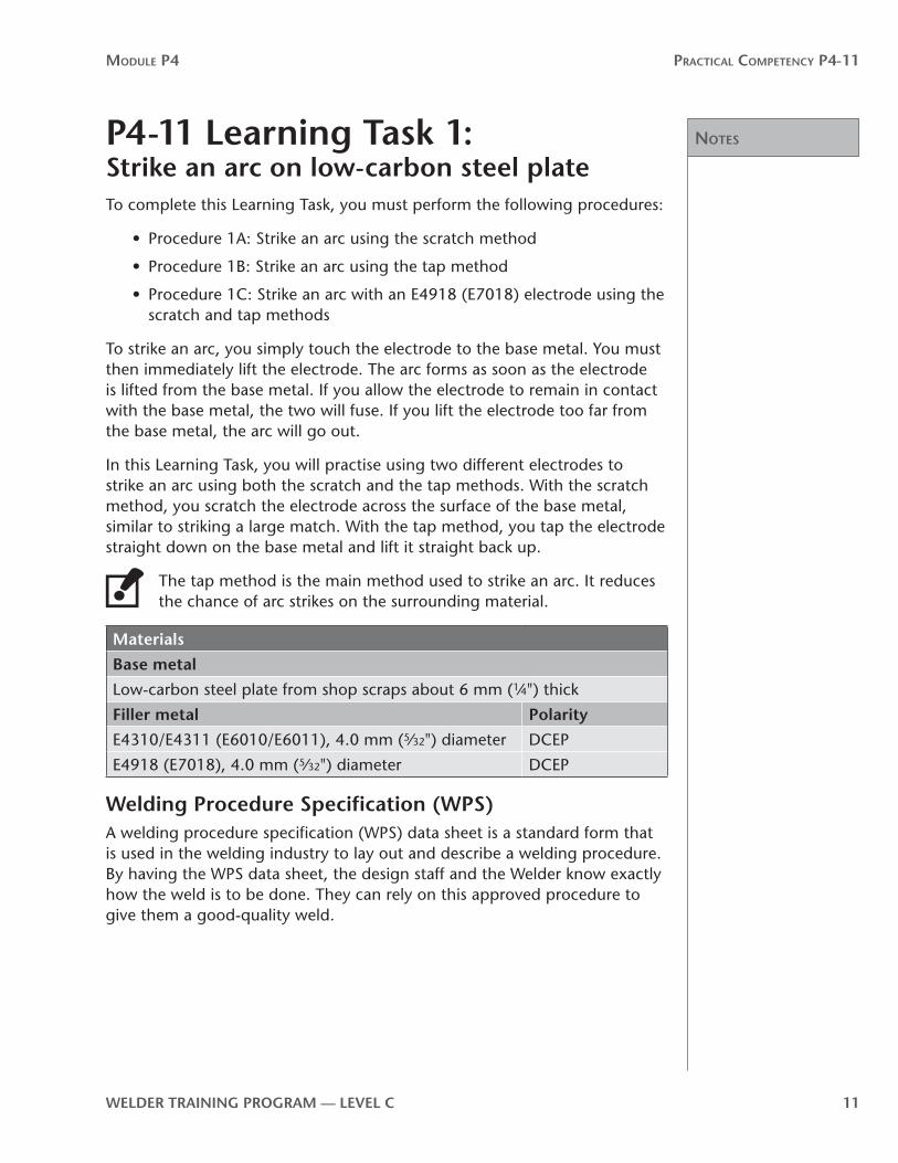
P4-11 learning Task 1:Strike an arc on low-carbon steel plateTo complete this Learning Task, you must perform the following procedures:
• Procedure 1A: Strike an arc using the scratch method
• Procedure 1B: Strike an arc using the tap method
• Procedure 1C: Strike an arc with an E4918 (E7018) electrode using the scratch and tap methods
To strike an arc, you simply touch the electrode to the base metal. You must then immediately lift the electrode. The arc forms as soon as the electrode is lifted from the base metal. If you allow the electrode to remain in contact with the base metal, the two will fuse. If you lift the electrode too far from the base metal, the arc will go out.
In this Learning Task, you will practise using two different electrodes to strike an arc using both the scratch and the tap methods. With the scratch method, you scratch the electrode across the surface of the base metal, similar to striking a large match. With the tap method, you tap the electrode straight down on the base metal and lift it straight back up.
The tap method is the main method used to strike an arc. It reduces the chance of arc strikes on the surrounding material.
Materials
Base metal
Low-carbon steel plate from shop scraps about 6 mm (1⁄4") thick
Filler metal Polarity
E4310/E4311 (E6010/E6011), 4.0 mm (5⁄32") diameter DCEP
E4918 (E7018), 4.0 mm (5⁄32") diameter DCEP
Welding Procedure Specification (WPS)A welding procedure specification (WPS) data sheet is a standard form that is used in the welding industry to lay out and describe a welding procedure. By having the WPS data sheet, the design staff and the Welder know exactly how the weld is to be done. They can rely on this approved procedure to give them a good-quality weld.
notes
Module P4 Practical coMPetency P4-11
12 WelDer TrAInInG PrOGrAM — level C
Some welding shops are certified by governing bodies that set standards in weld quality. This is done so that engineers and customers know that the Welders and their welds will meet a set standard of quality. Many shops are certified under the Canadian Welding Bureau (CWB) or the American Society of Mechanical Engineers (ASME). There are also shops certified for building ships, aircraft, railroad equipment and petrochemical equipment.
Welding and fabrication shops that are CWB certified often construct components of large structures that have to be built to design code. ASME-certified shops often build pressure vessels, piping systems and boilers. In both cases, faulty welds could have lethal results. Having a system of weld procedures that have been proven to meet code ensures that they will produce a safe product for the customer and end user.
At first your Practical Competencies will provide you with a step-by-step procedure to follow. Gradually, you will encounter simplified versions of a Welding Procedure Specification (WPS) data sheet in your Practical Competencies. This will help you become familiar with the format.
Eventually you will be able to read a one- or two-page WPS data sheet and understand what has to be done to make a quality weld. A WPS gives you all the information you require in an abbreviated form. The following is a sample WPS with descriptions of the information it contains.
notes
Module P4 Practical coMPetency P4-11
WelDer TrAInInG PrOGrAM — level C 13
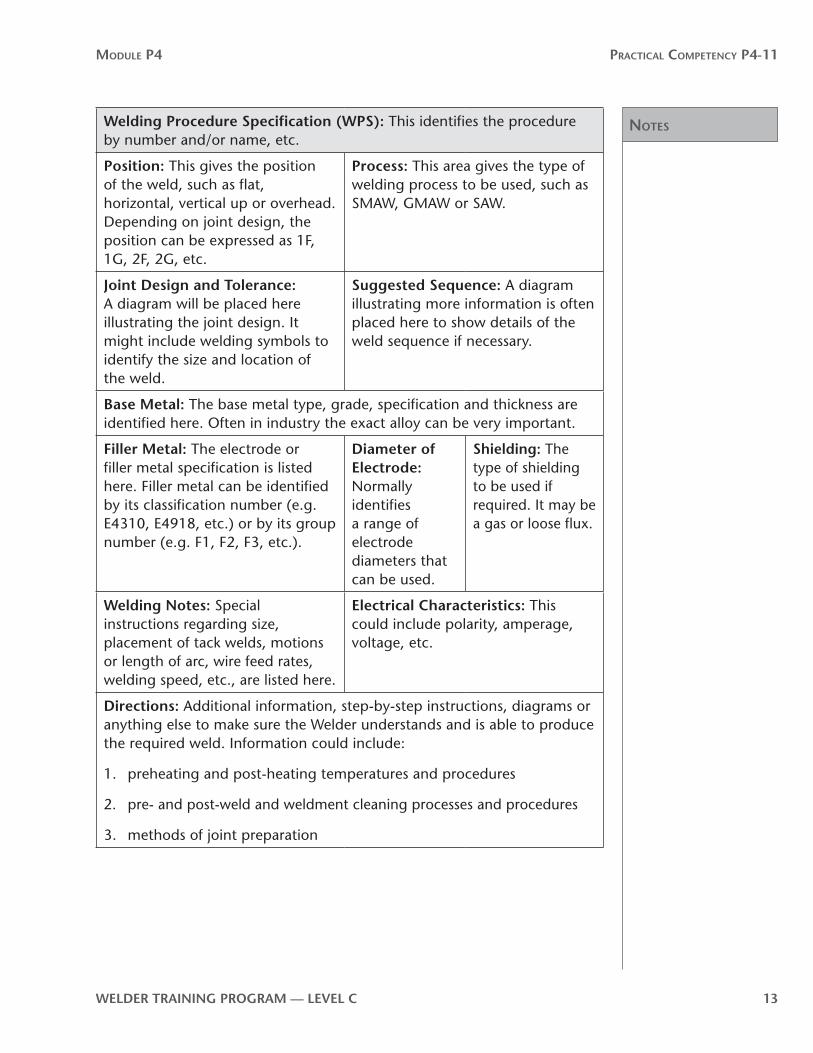
Welding Procedure Specification (WPS): This identifies the procedure by number and/or name, etc.
Position: This gives the position of the weld, such as flat, horizontal, vertical up or overhead. Depending on joint design, the position can be expressed as 1F, 1G, 2F, 2G, etc.
Process: This area gives the type of welding process to be used, such as SMAW, GMAW or SAW.
Joint Design and Tolerance: A diagram will be placed here illustrating the joint design. It might include welding symbols to identify the size and location of the weld.
Suggested Sequence: A diagram illustrating more information is often placed here to show details of the weld sequence if necessary.
Base Metal: The base metal type, grade, specification and thickness are identified here. Often in industry the exact alloy can be very important.
Filler Metal: The electrode or filler metal specification is listed here. Filler metal can be identified by its classification number (e.g. E4310, E4918, etc.) or by its group number (e.g. F1, F2, F3, etc.).
Diameter of electrode: Normally identifies a range of electrode diameters that can be used.
Shielding: The type of shielding to be used if required. It may be a gas or loose flux.
Welding notes: Special instructions regarding size, placement of tack welds, motions or length of arc, wire feed rates, welding speed, etc., are listed here.
electrical Characteristics: This could include polarity, amperage, voltage, etc.
Directions: Additional information, step-by-step instructions, diagrams or anything else to make sure the Welder understands and is able to produce the required weld. Information could include:
1. preheating and post-heating temperatures and procedures
2. pre- and post-weld and weldment cleaning processes and procedures
3. methods of joint preparation

notes
Module P4 Practical coMPetency P4-11
14 WelDer TrAInInG PrOGrAM — level C
WPS P4-11-1A:Strike an arc using the scratch methodDirections
1. Turn on the welding power source.
2. Set the welding power source by selecting the correct polarity and current settings for the E4310/E4311 (E6010/E6011) electrode.
3. Attach the ground clamp to your workpiece.
4. Insert the electrode into the electrode holder.
5. Hold the electrode about 25 mm (1 in.) above the base metal. It should be perpendicular to the base metal and inclined 10° to 20° in the direction of travel.
6. Lower your welding helmet and strike an arc by quickly and gently dragging the electrode across the base metal, using a wrist movement only (Figure 1). If you strike the arc correctly, a burst of light (an arc) will occur.
Scratch electrode across base metal with wrist movement only
Figure 1—Scratch method

notes
Module P4 Practical coMPetency P4-11
WelDer TrAInInG PrOGrAM — level C 15
7. Lift the electrode about 6 mm (1⁄4 in.). Hold this distance for a second or two. Then lower the electrode until it is 3 mm (1⁄8 in.) away from the base metal.
The purpose of holding a long arc for that second or two is to allow the tip to heat up, making the arc more stable. Maintain the arc for three or four seconds. Then pull the electrode away from the steel plate until the arc is broken.
8. Practise using the scratch method to strike an arc until you can do it smoothly every time. Keep your weld deposits on one-half of one side of the steel plate.
Use your electrode until it is a stub less than 50 mm (2 in.) long. Discard the stub in the metal container designated for stubs.
9. Always use pliers to position the plate after it has been exposed to the arc. It will get hot!
If you pick up hot metal with your gloves, you will burn the fingertips and harden the leather. The gloves will no longer insulate your fingers from the heat.
10. When you feel you can strike and maintain an arc smoothly, ask your instructor to evaluate your technique.

notes
Module P4 Practical coMPetency P4-11
16 WelDer TrAInInG PrOGrAM — level C
WPS P4-11-1B:Strike an arc using the tap methodDirections
1. Turn on the welding power source.
2. Set the welding power source by selecting the correct polarity and current settings for the E4310/E4311 (E6010/E6011) electrode.
3. Attach the ground clamp to your workpiece.
4. Insert the electrode into the electrode holder.
5. Hold the electrode about 25 mm (1 in.) (Figure 2A) above the base metal. It should be perpendicular to the base metal and inclined 10° to 20° in the direction of travel.
6. Lower your welding helmet and strike an arc by moving the electrode straight down until it touches the base metal (Figure 2B). When the burst of light occurs, bring the electrode up to 6 mm (1⁄4 in.) (Figure 2C) from the base metal.
Hold this length for a second or two, then lower the electrode until it is 3 mm (1⁄8 in.) (Figure 2D) away from the plate. Maintain the arc for three or four seconds, then break the arc by pulling the electrode away from the base metal.
25 mm (1")
6 mm (¼")
touch base metal
A. Start position B. Touch base metal
C. Raise electrode 6 mm (¼") D. Lower to 3 mm (1⁄8") to start welding
3 mm (1⁄8")
Figure 2—Tap method

notes
Module P4 Practical coMPetency P4-11
WelDer TrAInInG PrOGrAM — level C 17
7. Practise using the tap method to strike an arc until you can do it smoothly every time. Keep your weld deposits on the other half of the side of the base metal you used for Procedure 1A.
Use your electrode until it is a stub 50 mm (2 in.) long. Discard the stub in the metal container designated for stubs.
8. Always use pliers to position the plate after it has been exposed to the arc. It will get hot!
If you pick up hot metal with your gloves, you will burn the fingertips and harden the leather. The gloves will no longer insulate your fingers from the heat.
9. When you can strike and maintain an arc smoothly, ask your instructor to evaluate your technique.

notes
Module P4 Practical coMPetency P4-11
18 WelDer TrAInInG PrOGrAM — level C
WPS P4-11-1C:Strike an arc with an e4918 (e7018) electrode using the scratch and tap methodsDirections
1. Set the welding power source by selecting the correct polarity and current settings for the E4918 (E7018) electrode.
2. Follow the steps in Procedure 1A for the scratch method using the E4918 (E7018) electrode. Use the reverse side of your plate. Use your electrode until it is a stub less than 50 mm (2 in.) long. Discard the stub in a metal container designated for stubs.
3. Clean up your weldment by removing the slag and spatter with a chipping hammer and wire brush.
4. Follow the steps in Procedure 1B for the tap method using the E4918 (E7018) electrode.
5. When you can strike and maintain each arc smoothly, ask your instructor to evaluate your technique.

notes
Module P4 Practical coMPetency P4-11
WelDer TrAInInG PrOGrAM — level C 19
P4-11 learning Task 2:Bead welds in the flat position on low-carbon steel plateTo complete this Learning Task, you must perform the following procedures:
• Procedure 2A: Weld stringer beads in the flat position• Procedure 2B: Weld weave beads in the flat position

notes
Module P4 Practical coMPetency P4-11
20 WelDer TrAInInG PrOGrAM — level C
WPS P4-11-2A:Stringer bead welds in the flat position
Materials
Base metal
Low-carbon steel plate from shop scrap about 13 mm (1⁄2") thick
Filler metal Polarity
E4310/E4311 (E6010/E6011), 4 mm (5⁄32") diameter DCEP
E4918 (E7018), 4 mm (5⁄32") diameter DCEP
E4924 (E7024), 4 mm (5⁄32") diameter DCEN
Welding symbol
SMAW
Directions
1. Use your combination square and soapstone to lay out lines lengthwise 13 mm (1⁄2 in.) apart on both sides of your base metal (Figure 3). These lines will act as a guide so your beads are straight and evenly spaced.
13 mm (1⁄2")
Soapstone lines
Figure 3—Markings on the plate
2. Select the correct polarity and current settings for the E4310/E4311 (E6010/E6011) electrode. Attach the ground clamp to your workpiece. Insert the electrode in the electrode holder.

notes
Module P4 Practical coMPetency P4-11
WelDer TrAInInG PrOGrAM — level C 21
3. Position your workpiece so that you will be welding in the flat position.
4. Run a stringer bead along each of the layout lines. The bead should be about 6 mm (1⁄4 in.) wide (Figure 4). Adjust your rate of travel and electrode angle to achieve the correct size of bead. Be sure the weld is straight and consistent in width.
6 mm (1⁄4")
Figure 4—Stringer beads on plate
Generally, a stringer weld bead will be up to two times the outside diameter of the welding electrode, including flux. Heavier flux coatings produce wider beads for the same wire diameter.
Weave beads should be about three to a maximum of four times the outside diameter of the electrode.
5. Clean up your weldment by removing the slag and spatter with a chipping hammer and wire brush. Make sure you wear safety glasses and a full face shield or your welding helmet with the filter lens flipped up when cleaning your weld. With the soapstone, mark the plate with the type of electrode used. Always use pliers to pick up the plate.
6. Show your work to your instructor. He/she will evaluate your work for:
• correct bead width• reasonably smooth straight beads• absence of arc strikes• overall appearance
7. Repeat the steps in this procedure using the E4918 (E7018) and E4924 (E7024) electrodes.

notes
Module P4 Practical coMPetency P4-11
22 WelDer TrAInInG PrOGrAM — level C
WPS P4-11-2B:Weave bead welds in the flat position
Materials
Base metal
Low-carbon steel plate from shop scrap about 13 mm (1⁄2") thick
Filler metal Polarity
E4310/E4311 (E6010/E6011), 4 mm (5⁄32") diameter DCEP
E4918 (E7018), 4 mm (5⁄32") diameter DCEP
E4924 (E7024), 4 mm (5⁄32") diameter DCEN
Welding symbol
SMAW
Directions
1. Locate the plate that has the E4310/E4311 (E6010/E6011) stringer beads on it from the previous exercise.
2. Select the correct polarity and current settings for the E4310/E4311 (E6010/E6011) electrode. Attach the ground clamp to your workpiece. Insert the electrode in the electrode holder.
3. Position your workpiece so that you will be welding in the flat position.
4. Using a weave (zigzag) pattern, run a bead between two of the single-pass stringer beads, going from crown to crown (Figure 5).
Stringer bead Weave bead
6 mm (1⁄4")
Figure 5—Weave bead
notes
Module P4 Practical coMPetency P4-11
WelDer TrAInInG PrOGrAM — level C 23
5. Continue welding beads using the weave method until you fill this side of the plate.
6. Clean up your weldment by removing the slag and spatter. Make sure you wear safety glasses and a full face shield or your welding helmet with the filter lens flipped up when cleaning your weld. With the soapstone, mark the plate with the type of electrode used. Always use pliers to handle the hot plate.
7. Show your work to your instructor. He/she will evaluate your beads for:
• correct bead width• reasonably smooth beads• crown-to-crown bead placement• absence of arc strikes• overall appearance
8. Repeat the steps in this procedure using the E4918 (E7018) and E4924 (E7024) electrodes.

notes
Module P4 Practical coMPetency P4-11
24 WelDer TrAInInG PrOGrAM — level C

Practical comPetency P4-12:Fillet welds on low-carbon steel plate
P4
-12


WelDer TrAInInG PrOGrAM — level C 27
Module P4 Practical coMPetency P4-12
OutcomesIn this Practical Competency, you will learn to make SMAW fillet welds on low-carbon steel plates. You will practise welding in four positions on lap, tee and corner joints. You will also practise welding structural sections and pipe on plate.
When you have completed the procedures in Practical Competency P4-12, you will be able to make SMAW fillet welds using a variety of electrodes in the:
• 1F position on lap, tee and corner joints• 2F position on lap, tee and corner joints • 3F uphill position on lap, tee and corner joints • 4F position on lap, tee and corner joints • 2F position with structural sections on plate• 5F uphill position with pipe on plate
evaluationYou will be required to do the following:
• SMAW fillet welds on low-carbon steel plate in a variety of positions
Your instructor will evaluate your ability at each step.
MaterialsEach Learning Task identifies the materials and tools you will need to complete the assigned procedure. Your instructor will arrange for these tools and materials to be available to you.
WARNING!
If a Practical Competency Learning Task requires that you use a tool or piece of equipment that you have not previously operated—or you feel unsure about the operation of any tools or equipment—ask your instructor to demonstrate the correct procedures for the tool or piece of equipment before you use it.
Use of materialsWelding is a very expensive trade. The cost of steel, filler metal and other consumables can rise or fall, depending on the marketplace. The only area in which there can be significant potential savings is in how we use steel. Steel is the largest single consumable cost. This is true in both training and industry.
Training institutions often have to buy scrap material to practise on. Therefore, steel used for practise might not be the exact size or thickness laid out in the Practical Competencies. This will not affect your learning. In fact, it might even better reflect the reality of the real welding world, where it is common practise to substitute material sizes.

28 WelDer TrAInInG PrOGrAM — level C
Module P4 Practical coMPetency P4-12
When cutting new steel or steel crops, always strive for maximum use and minimum waste. Cut pieces from one end of plate so as to leave the largest possible area untouched for later use. Assemble lap joints and tee joints in a way that will reduce waste and maximize the size of off-cuts after welding.
General procedures for all welding Practical Competencies1. Arrange with your instructor for a demonstration of all procedures and for the
equipment you will need.
2. Follow all safety precautions, wear all personal protective clothing and use all personal protective equipment. Review P1-2: Use Safe Work Practises.
3. Clean the base metal, if necessary. Remove any rust, mill scale or paint.
4. You will be required to repeat procedures until you receive an acceptable evaluation from your instructor.

notes
Module P4 Practical coMPetency P4-12
WelDer TrAInInG PrOGrAM — level C 29
P4-12 learning Task 1:Fillet welds in the flat (1F) position on lap, tee and corner joints on low-carbon steel plateTo complete this Learning Task, you must perform the following welding procedures:
• Procedure 1A: Single-pass fillet welds on lap joints in the 1F position
• Procedure 1B: Multi-pass fillet welds on tee joints in the 1F position
• Procedure 1C: Multi-pass fillet welds on corner joints in the 1F position

notes
Module P4 Practical coMPetency P4-12
30 WelDer TrAInInG PrOGrAM — level C
WPS P4-12-1A:Single-pass fillet welds on lap joints in the 1F position
Materials
Base metal
Two pieces of low-carbon steel plate 10 mm or 13 mm (3⁄8" or 1⁄2") thick by 200 mm (8") wide
Filler metal Polarity
E4310/E4311 (E6010/E6011), 4 mm (5⁄32") diameter DCEP
E4918 (E7018), 4 mm (5⁄32") diameter DCEP
E4924 (E7024), 4 mm (5⁄32") diameter DCEN
Welding symbol
SMAW
Directions
1. Position your two plates to make a lap joint (Figure 6). Overlap the plates no more than one thickness. Make sure the plates are tight together. Align the ends of the joint so the plates are flush with each other.
t
t
t = thickness
Figure 6—lap joint plate alignment
2. Select the correct polarity and current setting for the E4310/E4311 (E6010/E6011) electrode. Attach the ground clamp to your workpiece. Insert the electrode in the electrode holder.

Notes
Module P4 Practical coMPetency P4-12
WelDer TrAInInG PrOGrAM — level C 31
3. Make four tack welds 19 mm (3⁄4 in.) long, one at each end of the joint (Figure 7) and another two on the opposite side of the joint. Show your tack welds to your instructor before proceeding with the weld.
Tack welds19 mm (¾")
tTack welds
Figure 7—lap joint tack welds
4. When your instructor has approved your tack welds, place the joint at a 45° angle to achieve the true 1F position (Figure 8).
45º
Figure 8—lap joint in the 1F position

Notes
Module P4 Practical coMPetency P4-12
32 WelDer TrAInInG PrOGrAM — level C
5. Weld along the joint (Figure 9). Watch for excessive buildup or undercut. Adjust your rate of travel or electrode angle as necessary. Be sure the legs of the fillet weld are equal in length.
45º
Figure 9—Completed fillet weld on a lap joint
6. Clean up your weldment by removing the slag and spatter with a chipping hammer and wire brush.
7. Show your work to your instructor. He/she will evaluate it for:
• correct alignment• good penetration• good fusion• absence of porosity• absence of undercut• overall appearance• absence of arc strikes• reasonable smoothness• absence of irregularities• legs of equal length• slightly convex profile
8. Repeat the procedure using the E4918 (E7018) and E4924 (E7024) electrodes.

notes
Module P4 Practical coMPetency P4-12
WelDer TrAInInG PrOGrAM — level C 33

Notes
Module P4 Practical coMPetency P4-12
34 WelDer TrAInInG PrOGrAM — level C
WPS P4-12-1B:Multi-pass fillet welds on tee joints in the 1F position
Materials
Base metal
Two pieces of low-carbon steel plate 10 mm or 13 mm (3⁄8" or 1⁄2") thick by 200 mm (8") wide
Filler metal Polarity
E4310/E4311 (E6010/E6011), 4 mm (5⁄32") diameter DCEP
E4918 (E7018), 4 mm (5⁄32") diameter DCEP
E4924 (E7024), 4 mm (5⁄32") diameter DCEN
Welding symbol
SMAW
Directions
1. Position your two plates to make a tee joint. Set the vertical piece two thicknesses in from the edge of the bottom plate. Make sure that the bottom plate lies flat on the work surface and the vertical plate forms the tee at 90° to the bottom plate (Figure 10). Align the ends of the joint so the plates are flush with each other.
90º
Figure 10—Tee joint plate alignment

notes
Module P4 Practical coMPetency P4-12
WelDer TrAInInG PrOGrAM — level C 35
2. Select the correct polarity and current setting for the E4310/E4311 (E6010/E6011) electrode. Attach the ground clamp to your workpiece. Insert the electrode in the electrode holder. Tack weld the joint (Figure 11).
Tack welds90º
Figure 11—Tee joint tack welds
3. Place the tee joint at a 45° angle to achieve the true 1F position (Figure 12).
Tack welds
45º
Figure 12—Tee joint in the 1F position
Notes
Module P4 Practical coMPetency P4-12
36 WelDer TrAInInG PrOGrAM — level C
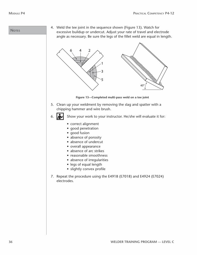
4. Weld the tee joint in the sequence shown (Figure 13). Watch for excessive buildup or undercut. Adjust your rate of travel and electrode angle as necessary. Be sure the legs of the fillet weld are equal in length.
6 4 2
1
3
5
45º
Figure 13—Completed multi-pass weld on a tee joint
5. Clean up your weldment by removing the slag and spatter with a chipping hammer and wire brush.
6. Show your work to your instructor. He/she will evaluate it for:
• correct alignment• good penetration• good fusion• absence of porosity• absence of undercut• overall appearance• absence of arc strikes• reasonable smoothness• absence of irregularities• legs of equal length• slightly convex profile
7. Repeat the procedure using the E4918 (E7018) and E4924 (E7024) electrodes.

notes
Module P4 Practical coMPetency P4-12
WelDer TrAInInG PrOGrAM — level C 37

Notes
Module P4 Practical coMPetency P4-12
38 WelDer TrAInInG PrOGrAM — level C
WPS P4-12-1C:Multi-pass fillet welds on corner joints in the 1F position
Materials
Base metal
Two pieces of low-carbon steel plate 10 mm or 13 mm (3⁄8" or 1⁄2") thick by 200 mm (8") wide
Filler metal Polarity
E4310/E4311 (E6010/E6011), 4 mm (5⁄32") diameter DCEP
E4918 (E7018), 4 mm (5⁄32") diameter DCEP
E4924 (E7024), 4 mm (5⁄32") diameter DCEN
Welding symbol
SMAW
Directions
1. Position your two plates at 90° to each other for an open corner joint (Figure 14). Align the ends of the joint so the plates are flush with each other.
90º
Figure 14—Open corner joint plate alignment

notes
Module P4 Practical coMPetency P4-12
WelDer TrAInInG PrOGrAM — level C 39
2. Select the correct polarity and current setting for the E4310/E4311 (E6010/E6011) electrode. Attach the ground clamp to your workpiece. Insert the electrode in the electrode holder.
3. Make two tack welds 19 mm (3⁄4 in.) long, one at each end of the joint (Figure 15).
Tack welds19 mm (¾")
Figure 15—Corner joint tack welds
4. Place the corner joint in the true flat (1F) position (Figure 16).
5. Weld the joint (Figure 16). Take care to avoid excessive buildup by adjusting your rate of travel and electrode angle as necessary. Be sure the legs of the fillet weld are equal in length.
321
Figure 16—Completed multi-pass fillet weld on an open corner joint
Notes
Module P4 Practical coMPetency P4-12
40 WelDer TrAInInG PrOGrAM — level C
6. Clean up your weldment by removing the slag and spatter with a chipping hammer and wire brush.
7. Show your work to your instructor. He/she will evaluate it for:
• correct alignment• good penetration• good fusion• absence of porosity• absence of undercut• overall appearance• absence of arc strikes• reasonable smoothness• absence of irregularities• legs of equal length• slightly convex profile
8. Repeat the procedure using the E4918 (E7018) and E4924 (E7024) electrodes.

Notes
Module P4 Practical coMPetency P4-12
WelDer TrAInInG PrOGrAM — level C 41
P4-12 learning Task 2:Fillet welds in the horizontal (2F) position on lap, tee and corner joints on low-carbon steel plateTo complete this Learning Task, you must perform the following welding procedures:
• Procedure 2A: Multi-pass fillet welds on lap joints in the 2F position
• Procedure 2B: Multi-pass fillet welds on tee joints in the 2F position
• Procedure 2C: Multi-pass fillet welds on corner joints in the 2F position

Notes
Module P4 Practical coMPetency P4-12
42 WelDer TrAInInG PrOGrAM — level C
WPS P4-12-2A:Multi-pass fillet welds on lap joints in the 2F position
Materials
Base metal
Two pieces of low-carbon steel plate 10 mm or 13 mm (3⁄8" or 1⁄2") thick by 200 mm (8") wide
Filler metal Polarity
E4310/E4311 (E6010/E6011), 4 mm (5⁄32") diameter DCEP
E4918 (E7018), 4 mm (5⁄32") diameter DCEP
E4924 (E7024), 4 mm (5⁄32") diameter DCEN
Welding symbol
SMAW
Directions
1. Position your two plates to make a lap joint (Figure 17). Overlap the plates no more than one thickness. Make sure the plates are tight together. Align the ends of the joint so the plates are flush with each other.
t
t
t = thickness
Figure 17—lap joint plate alignment
2. Select the correct polarity and current settings for the E4310/E4311 (E6010/E6011) electrode. Secure the ground clamp to your workpiece. Insert the electrode in the electrode holder.
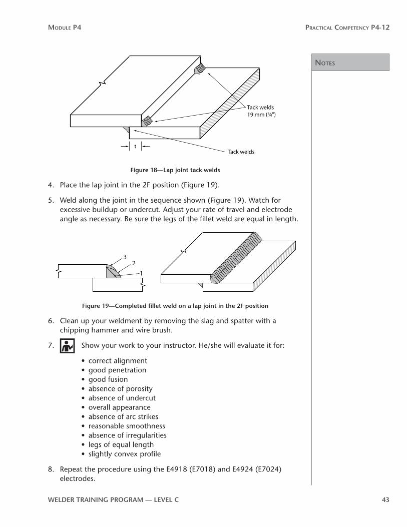
3. Make four tack welds 19 mm (3⁄4 in.) long, one at each end of the joint (Figure 18) and another two on the opposite side of the joint.
Notes
Module P4 Practical coMPetency P4-12
WelDer TrAInInG PrOGrAM — level C 43
Tack welds19 mm (¾")
tTack welds
Figure 18—lap joint tack welds
4. Place the lap joint in the 2F position (Figure 19).
5. Weld along the joint in the sequence shown (Figure 19). Watch for excessive buildup or undercut. Adjust your rate of travel and electrode angle as necessary. Be sure the legs of the fillet weld are equal in length.
32
1
Figure 19—Completed fillet weld on a lap joint in the 2F position
6. Clean up your weldment by removing the slag and spatter with a chipping hammer and wire brush.
7. Show your work to your instructor. He/she will evaluate it for:
• correct alignment• good penetration• good fusion• absence of porosity• absence of undercut• overall appearance• absence of arc strikes• reasonable smoothness• absence of irregularities• legs of equal length• slightly convex profile
8. Repeat the procedure using the E4918 (E7018) and E4924 (E7024) electrodes.

Notes
Module P4 Practical coMPetency P4-12
44 WelDer TrAInInG PrOGrAM — level C
WPS P4-12-2B:Multi-pass fillet welds on tee joints in the 2F position
Materials
Base metal
Two pieces of low-carbon steel plate 10 mm or 13 mm (3⁄8" or 1⁄2") thick by 200 mm (8") wide
Filler metal Polarity
E4310/E4311 (E6010/E6011), 4 mm (5⁄32") diameter DCEP
E4918 (E7018), 4 mm (5⁄32") diameter DCEP
E4924 (E7024), 4 mm (5⁄32") diameter DCEN
Welding symbol
SMAW
Directions
1. Position your two plates to make a tee joint. Set the vertical piece two thicknesses in from the edge of the bottom plate. Make sure that the bottom plate lies flat on the work surface and the vertical plate forms the tee at 90° to the bottom plate (Figure 20). Align the ends of the joint so the plates are flush with each other.
90º
Figure 20—Tee joint plate alignment

Notes
Module P4 Practical coMPetency P4-12
WelDer TrAInInG PrOGrAM — level C 45
2. Select the correct polarity and current setting for the E4310/E4311 (E6010/E6011) electrode. Attach the ground clamp to your workpiece. Insert the electrode in the electrode holder.
3. Make four tack welds 19 mm (3⁄4 in.) long, one at each end of the joint and another two on the opposite side of the joint (Figure 21).
Tack welds90º
Figure 21—Tee joint tack welds
4. Place the tee joint in the 2F position (Figure 22).
5. Weld the tee joint (Figure 22). Watch for excessive buildup or undercut. Adjust your rate of travel and electrode angle as necessary. Be sure the legs of the fillet weld are equal in length.
6
4
2 1
3
5
Figure 22—Completed fillet weld on a tee joint in the 2F position

Notes
Module P4 Practical coMPetency P4-12
46 WelDer TrAInInG PrOGrAM — level C
6. Clean up your weldment by removing the slag and spatter with a chipping hammer and wire brush.
7. Show your work to your instructor. He/she will evaluate it for:
• correct alignment• good penetration• good fusion• absence of porosity• absence of undercut• overall appearance• absence of arc strikes• reasonable smoothness• absence of irregularities• legs of equal length• slightly convex profile
8. Repeat the procedure using the E4918 (E7018) and E4924 (E7024) electrodes.

notes
Module P4 Practical coMPetency P4-12
WelDer TrAInInG PrOGrAM — level C 47

Notes
Module P4 Practical coMPetency P4-12
48 WelDer TrAInInG PrOGrAM — level C
WPS P4-12-2C:Multi-pass fillet welds on corner joints in the 2F position
Materials
Base metal
Two pieces of low-carbon steel plate 10 mm or 13 mm (3⁄8" or 1⁄2") thick by 200 mm (8") wide
Filler metal Polarity
E4310/E4311 (E6010/E6011), 4 mm (5⁄32") diameter DCEP
E4918 (E7018), 4 mm (5⁄32") diameter DCEP
E4924 (E7024), 4 mm (5⁄32") diameter DCEN
Welding symbol
SMAW
Directions
1. Position your two plates at 90° to each other for an open corner joint (Figure 23). Align the ends of the joint so the plates are flush with each other.
90º
Figure 23—Open corner joint plate alignment

notes
Module P4 Practical coMPetency P4-12
WelDer TrAInInG PrOGrAM — level C 49
2. Select the correct polarity and current setting for the E4310/E4311 (E6010/E6011) electrode. Attach the ground clamp to your workpiece. Insert the electrode in the electrode holder.
3. Make two tack welds 19 mm (3⁄4 in.) long, one at each end of the joint (Figure 24).
Tack welds19 mm (¾")
Figure 24—Tack welds
4. Place the open corner joint in the 2F position (Figure 25).
Figure 25—Corner joint in the 2F position

Notes
Module P4 Practical coMPetency P4-12
50 WelDer TrAInInG PrOGrAM — level C
5. Weld the joint in the sequence shown (Figure 26). Take care to avoid excessive buildup by adjusting your rate of travel and electrode angle as necessary. Be sure the legs of the fillet weld are equal in length.
32
1
Figure 26—Completed multi-pass fillet weld on an open corner joint in the 2F position
6. Clean up your weldment by removing the slag and spatter with a chipping hammer and wire brush.
7. Show your work to your instructor. He/she will evaluate it for:
• correct alignment• good penetration• good fusion• absence of porosity• absence of undercut• overall appearance• absence of arc strikes• reasonable smoothness• absence of irregularities• legs of equal length• slightly convex profile
8. Repeat the procedure using the E4918 (E7018) and E4924 (E7024) electrodes.
Notes
Module P4 Practical coMPetency P4-12
WelDer TrAInInG PrOGrAM — level C 51
P4-12 learning Task 3:Fillet welds in the vertical (3F) uphill position on lap, tee and corner joints on low-carbon steel plateTo complete this Learning Task, you must perform the following welding procedures:
• Procedure 3A: Single-pass fillet welds on lap joints in the 3F uphill position
• Procedure 3B: Multi-pass fillet welds on tee joints in the 3F uphill position
• Procedure 3C: Multi-pass fillet welds on corner joints in the 3F uphill position

Notes
Module P4 Practical coMPetency P4-12
52 WelDer TrAInInG PrOGrAM — level C
WPS P4-12-3A:Single-pass fillet welds on lap joints in the 3F uphill position
Materials
Base metal
Two pieces of low-carbon steel plate 10 mm or 13 mm (3⁄8" or 1⁄2") thick by 200 mm (8") wide
Filler metal Polarity
E4310/E4311 (E6010/E6011), 4 mm (5⁄32") diameter DCEP
E4918 (E7018), 3.2 mm (1⁄8") diameter DCEP
Welding symbol
SMAW
Directions
1. Position your two plates to make a lap joint (Figure 27). Overlap the plates no more than one thickness. Make sure the plates are tight together. Align the ends of the joint so the plates are flush with each other.
2. Select the correct polarity and current settings for the E4310/E4311 (E6010/E6011) electrode. Secure the ground clamp to your workpiece. Insert the electrode in the electrode holder.
3. Make four tack welds 19 mm (3⁄4 in.) long, one at each end of the joint and another two on the opposite side of the joint.

Notes
Module P4 Practical coMPetency P4-12
WelDer TrAInInG PrOGrAM — level C 53
4. Place the joint in the 3F position (Figure 27).
Figure 27—lap joint in the 3F position
5. Travelling uphill, weld the joint completely using one pass only (Figure 28). Watch for excessive buildup or undercut. Adjust your rate of travel and electrode angle as necessary. Be sure the legs of the fillet weld are equal in length.
Figure 28—Completed fillet weld on a lap joint in 3F position

Notes
Module P4 Practical coMPetency P4-12
54 WelDer TrAInInG PrOGrAM — level C
6. Clean up your weldment by removing the slag and spatter with a chipping hammer and wire brush.
7. Show your work to your instructor. He/she will evaluate it for:
• correct alignment• good penetration• good fusion• absence of porosity• absence of undercut• overall appearance• absence of stray arcs• reasonable smoothness• absence of irregularities• legs of equal length• slightly convex profile
8. Repeat the procedure using the E4918 (E7018) electrode.

notes
Module P4 Practical coMPetency P4-12
WelDer TrAInInG PrOGrAM — level C 55

Notes
Module P4 Practical coMPetency P4-12
56 WelDer TrAInInG PrOGrAM — level C
WPS P4-12-3B:Multi-pass fillet welds on tee joints in the 3F (uphill) position
Materials
Base metal
Two pieces of low-carbon steel plate 10 mm or 13 mm (3⁄8" or 1⁄2") thick by 200 mm (8") wide
Filler metal Polarity
E4310/E4311 (E6010/E6011), 3.2 mm (1⁄8") diameter DCEP
E4310/E4311 (E6010/E6011), 4 mm (5⁄32") diameter DCEP
E4918 (E7018), 3.2 mm (1⁄8") diameter DCEP
E4918 (E7018), 4 mm (5⁄32") diameter DCEP
Welding symbol
SMAW
Directions
1. Position your two plates to make a tee joint. Set the vertical piece two thicknesses in from the edge of the bottom plate. Make sure that the bottom plate lies flat on the work surface and the vertical plate forms the tee at 90° to the bottom plate. Align the ends of the joint so the plates are flush with each other.
2. Select the correct polarity and current setting for the E4310/E4311 (E6010/E6011) 3.2 mm (1⁄8 in.) diameter electrode. Attach the ground clamp to your workpiece. Insert the electrode in the electrode holder.
3. Make four tack welds 19 mm (3⁄4 in.) long, one at each end of the joint and another two on the opposite side of the joint.
4. Place the tee joint in the 3F position (Figure 29).

notes
Module P4 Practical coMPetency P4-12
WelDer TrAInInG PrOGrAM — level C 57
Figure 29—Tee joint in the 3F position
5. Travelling uphill, weld your first two passes. Then change to the E4310/E4311 (E6010/E6011) 4 mm (5⁄32 in.) diameter electrode to complete the weld (Figure 30). Watch for excessive buildup or undercut. Adjust your rate of travel and electrode angle as necessary. Be sure the legs of the fillet weld are equal in length.
6
4
2
135
Figure 30—Completed multi-pass tee weld in the 3F uphill position
6. Show your work to your instructor. He/she will evaluate it for:
• correct alignment• good penetration• good fusion• absence of porosity• absence of undercut• overall appearance• absence of arc strikes• reasonable smoothness• absence of irregularities• legs of equal length• slightly convex profile
7. Repeat the procedure using the E4918 (E7018) 3.2 mm (1⁄8 in.) diameter electrode for the first two passes. Then change to the E4918 (E7018) 4 mm (5⁄32 in.) diameter electrode to complete the weld.

Notes
Module P4 Practical coMPetency P4-12
58 WelDer TrAInInG PrOGrAM — level C
WPS P4-12-3C:Multi-pass fillet welds on corner joints in the 3F uphill position
Materials
Base metal
Two pieces of low-carbon steel plate 10 mm or 13 mm (3⁄8" or 1⁄2") thick by 200 mm (8") wide
Filler metal Polarity
E4310/E4311 (E6010/E6011), 4 mm (5⁄32") diameter DCEP
E4918 (E7018), 3.2 mm (1⁄8") diameter DCEP
Welding symbol
SMAW
Directions
1. Position your two plates at 90° to each other for an open corner joint. Align the ends of the joint so the plates are flush with each other.
2. Select the correct polarity and current setting for the E4310/E4311 (E6010/E6011) electrode. Attach the ground clamp to your workpiece. Insert the electrode in the electrode holder.
3. Make two tack welds 19 mm (3⁄4 in.) long, one at each end of the joint.
4. Place the tee joint in the 3F position.
5. Travelling uphill, weld the joint (Figure 31). Take care to avoid excessive buildup by adjusting your rate of travel and electrode angle as necessary. Be sure the legs of the fillet weld are equal in length.

Notes
Module P4 Practical coMPetency P4-12
WelDer TrAInInG PrOGrAM — level C 59
321
Figure 31—Completed multi-pass fillet weld on an open corner joint in the 3F uphill position
6. Clean up your weldment by removing the slag and spatter with a chipping hammer and wire brush.
7. Show your work to your instructor. He/she will evaluate it for:
• correct alignment• good penetration• good fusion• absence of porosity• absence of undercut• overall appearance• absence of arc strikes• reasonable smoothness• absence of irregularities• legs of equal length• slightly convex profile
8. Repeat the procedure using the E4918 (E7018) electrode.

notes
Module P4 Practical coMPetency P4-12
60 WelDer TrAInInG PrOGrAM — level C

Notes
Module P4 Practical coMPetency P4-12
WelDer TrAInInG PrOGrAM — level C 61
P4-12 learning Task 4:Fillet welds in the overhead (4F) position on lap, tee and corner joints on low-carbon steel plateTo complete this Learning Task, you must perform the following procedures:
• Procedure A: Multi-pass fillet welds on lap joints in the 4F position
• Procedure B: Multi-pass fillet welds on tee joints in the 4F position
• Procedure C: Multi-pass fillet welds on corner joints in the 4F position

notes
Module P4 Practical coMPetency P4-12
62 WelDer TrAInInG PrOGrAM — level C
WPS P4-12-4A:Multi-pass fillet welds on lap joints in the 4F position
Materials
Base metal
Two pieces of low-carbon steel plate 10 mm or 13 mm (3⁄8" or 1⁄2") thick by 200 mm (8") wide
Filler metal Polarity
E4310/E4311 (E6010/E6011), 4 mm (5⁄32") diameter DCEP
E4918 (E7018), 3.2 mm (1⁄8") diameter DCEP
Welding symbol
SMAW
Directions
1. Position your two plates to make a lap joint (Figure 32). Overlap the plates no more than one thickness. Make sure the plates are tight together. Align the ends of the joint so the plates are flush with each other.
2. Select the correct polarity and current settings for the E4310/E4311 (E6010/E6011) electrode. Secure the ground clamp to your workpiece. Insert the electrode in the elctrode holder.
3. Make four tack welds 19 mm (3⁄4 in.) long, one at each end of the joint and another two on the opposite side of the joint.
4. Place the joint in the 4F position (Figure 32).
Figure 32—lap joint in the 4F position
Notes
Module P4 Practical coMPetency P4-12
WelDer TrAInInG PrOGrAM — level C 63
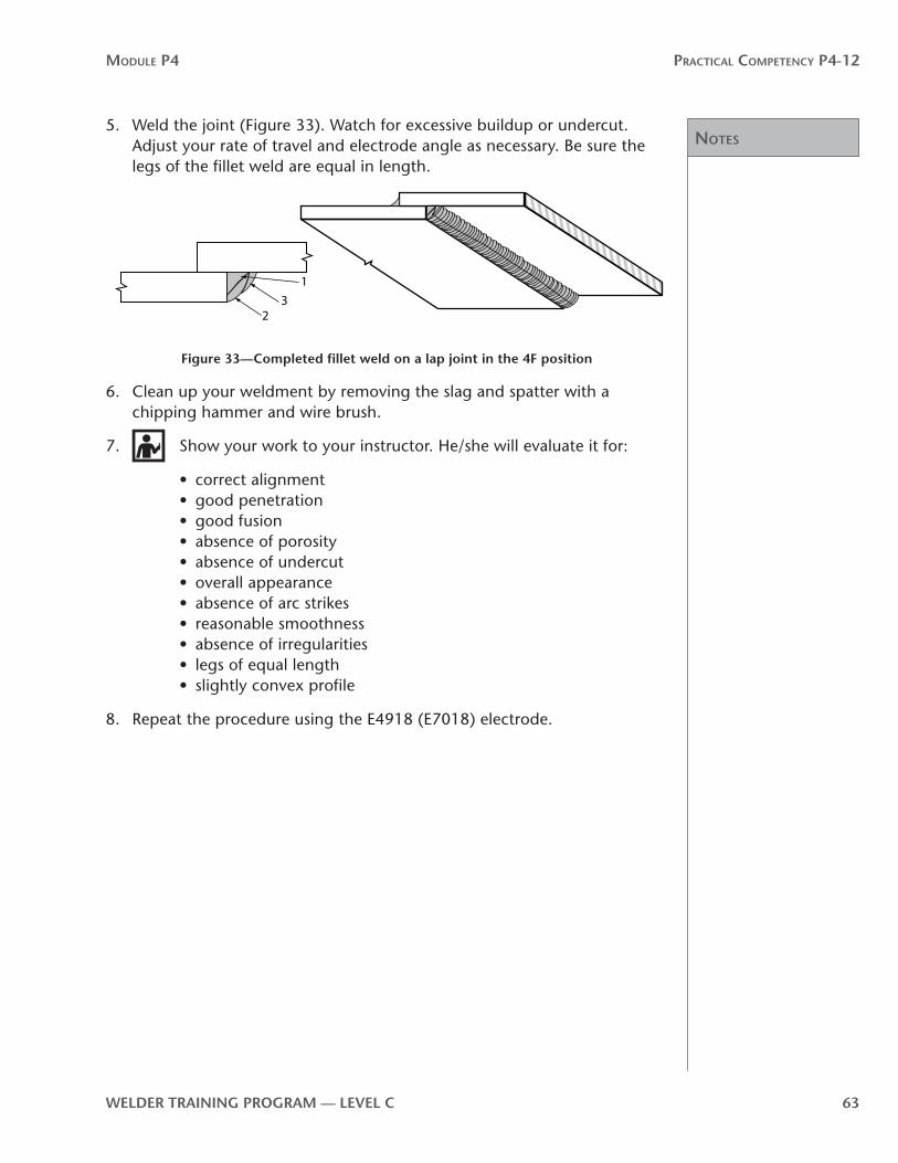
5. Weld the joint (Figure 33). Watch for excessive buildup or undercut. Adjust your rate of travel and electrode angle as necessary. Be sure the legs of the fillet weld are equal in length.
32
1
Figure 33—Completed fillet weld on a lap joint in the 4F position
6. Clean up your weldment by removing the slag and spatter with a chipping hammer and wire brush.
7. Show your work to your instructor. He/she will evaluate it for:
• correct alignment• good penetration• good fusion• absence of porosity• absence of undercut• overall appearance• absence of arc strikes• reasonable smoothness• absence of irregularities• legs of equal length• slightly convex profile
8. Repeat the procedure using the E4918 (E7018) electrode.

Notes
Module P4 Practical coMPetency P4-12
64 WelDer TrAInInG PrOGrAM — level C
WPS P4-12-4B:Multi-pass fillet welds on tee joints in the 4F position
Materials
Base metal
Two pieces of low-carbon steel plate 10 mm or 13 mm (3⁄8" or 1⁄2") thick by 200 mm (8") wide
Filler metal Polarity
E4310/E4311 (E6010/E6011), 4 mm (5⁄32") diameter DCEP
E4918 (E7018), 3.2 mm (1⁄8") diameter DCEP
Welding symbol
SMAW
Directions
1. Position your two plates to make a tee joint. Set the vertical piece two thicknesses in from the edge of the bottom plate. Make sure that the bottom plate lies flat on the work surface and the vertical plate forms the tee at 90° to the bottom plate. Align the ends of the joint so the plates are flush with each other.
2. Select the correct polarity and current setting for the E4310/E4311 (E6010/E6011) electrode. Attach the ground clamp to your workpiece. Insert the electrode in the electrode holder.
3. Make four tack welds 19 mm (3⁄4 in.) long, one at each end of the joint and another two on the opposite side of the joint.

Notes
Module P4 Practical coMPetency P4-12
WelDer TrAInInG PrOGrAM — level C 65
4. Place the tee joint in the 4F position (Figure 34).
Figure 34—Tee joint in the 4F position
5. Weld the joint in the sequence shown (Figure 35). Watch for excessive buildup or undercut. Adjust your rate of travel and electrode angle as necessary. Be sure the legs of the fillet weld are equal in length.
6
42 1
3
5
Figure 35—Completed multi-pass fillet weld in the 4F position
6. Show your work to your instructor. He/she will evaluate it for:
• correct alignment• good penetration• reasonable smoothness• legs of equal length• absence of undercut• absence of arc strikes• absence of irregularities• absence of porosity• slightly convex profile
7. Repeat the procedure using the E4918 (E7018) electrode.

Notes
Module P4 Practical coMPetency P4-12
66 WelDer TrAInInG PrOGrAM — level C
WPS P4-12-4C:Multi-pass fillet welds on corner joints in the 4F position
Materials
Base metal
Two pieces of low-carbon steel plate 10 mm or 13 mm (3⁄8" or 1⁄2") thick by 200 mm (8") wide
Filler metal Polarity
E4310/E4311 (E6010/E6011), 4 mm (5⁄32") diameter DCEP
E4918 (E7018), 3.2 mm (1⁄8") diameter DCEP
Welding symbol
SMAW
Directions
1. Position your two plates at 90° to each other for an open corner joint. Align the ends of the joint so the plates are flush with each other.
2. Select the correct polarity and current setting for the E4310/E4311 (E6010/E6011) electrode. Attach the ground clamp to your workpiece. Insert the electrode in the electrode holder.
3. Make two tack welds 19 mm (3⁄4 in.) long, one at each end of the joint.

Notes
Module P4 Practical coMPetency P4-12
WelDer TrAInInG PrOGrAM — level C 67
4. Place the tee joint in the 4F position (Figure 36).
Figure 36—Overhead (4F) position
5. Weld the joint in the sequence shown (Figure 37). Watch for excessive buildup or undercut. Adjust your rate of travel and electrode angle as necessary. Be sure the legs of the fillet weld are equal in length.
32
1
Figure 37—Completed multi-pass fillet weld on an open corner joint in the 4F position
6. Clean up your weldment by removing the slag and spatter with a chipping hammer and wire brush.
7. Show your work to your instructor. He/she will evaluate it for:
• correct alignment• good penetration• good fusion• absence of porosity• absence of undercut
• overall appearance• reasonable smoothness• absence of irregularities• legs of equal length• slightly convex profile
8. Repeat the procedure using the E4918 (E7018) electrode.

notes
Module P4 Practical coMPetency P4-12
68 WelDer TrAInInG PrOGrAM — level C
Notes
Module P4 Practical coMPetency P4-12
WelDer TrAInInG PrOGrAM — level C 69
P4-12 learning Task 5:Weld a pipe or structural section to a plate in the horizontal (2F) positionTo complete this Learning Task, you must perform the following procedure:
• Multi-pass fillet weld joining the end of a structural section to a plate

notes
Module P4 Practical coMPetency P4-12
70 WelDer TrAInInG PrOGrAM — level C
WPS P4-12-5:Multi-pass fillet weld joining the end of a structural section to a plate
Materials
Base metal
One piece of structural section (to be removed and salvaged after exercise). Suitable sections would be a wide flange beam or channel.
One piece of low-carbon steel plate about 10 mm × 175 mm × 175 mm (3⁄8" × 7" × 7")
Filler metal Polarity
E4918 (E7018), 4 mm (5⁄32") diameter DCEP
Welding symbol
SMAW
Directions
1. Position the structural section onto the plate and tack weld in place. The spacing and location of tack welds will vary according to the size and shape of the structural section.
2. Set the assembly so that the face of the plate is in the flat plane and the structural section is in the vertical plane.
3. Weld a horizontal fillet weld all around. Note that arc blow might occur when you weld into the corners of structural shapes.
4. Fill craters properly. Make sure that the fillet legs are equal in length and that they wrap around outside corners without becoming smaller.
5. Show your work to your instructor. He/she will evaluate it for:
• correct alignment• good penetration• good fusion• absence of porosity• absence of undercut• overall appearance
• absence of arc strikes• reasonable smoothness• absence of irregularities• legs of equal length• slightly convex profile

Notes
Module P4 Practical coMPetency P4-12
WelDer TrAInInG PrOGrAM — level C 71
P4-12 learning Task 6:Weld pipe to plate in the 5F positionTo complete this Learning Task, you must perform the following procedure:
• Multi-pass fillet weld between a pipe and a vertical plate
Notes
Module P4 Practical coMPetency P4-12
72 WelDer TrAInInG PrOGrAM — level C
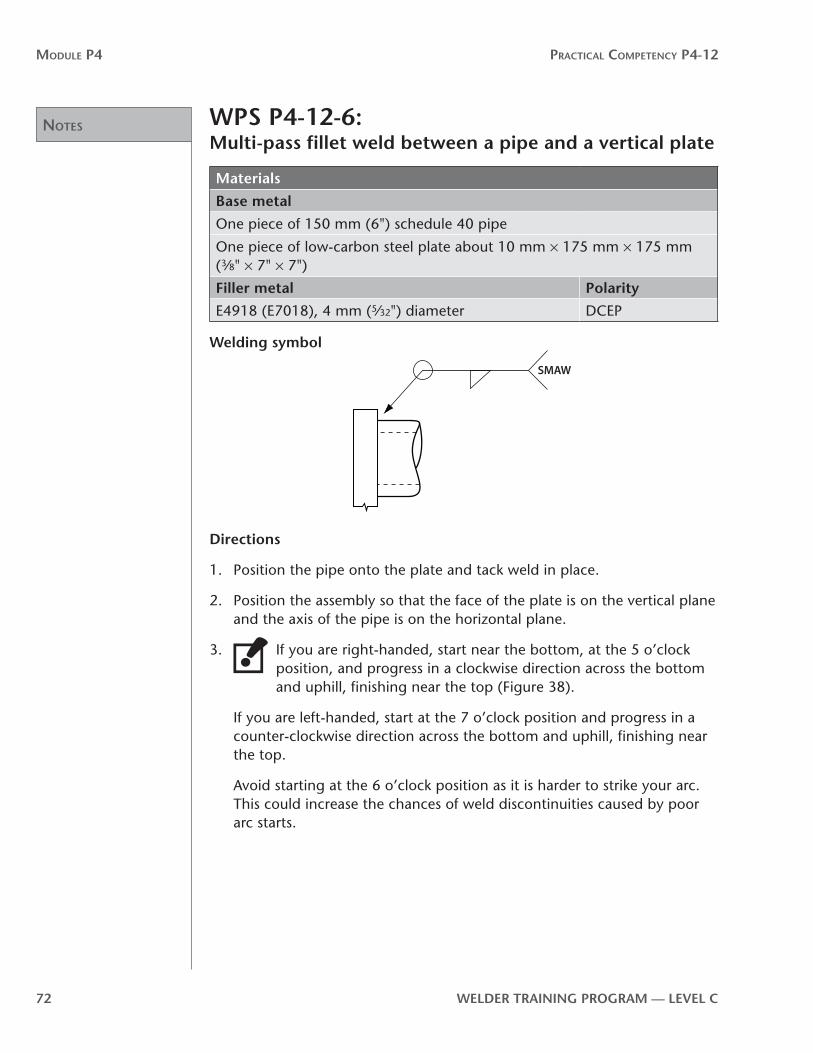
WPS P4-12-6:Multi-pass fillet weld between a pipe and a vertical plate
Materials
Base metal
One piece of 150 mm (6") schedule 40 pipe
One piece of low-carbon steel plate about 10 mm × 175 mm × 175 mm (3⁄8" × 7" × 7")
Filler metal Polarity
E4918 (E7018), 4 mm (5⁄32") diameter DCEP
Welding symbol
SMAW
Directions
1. Position the pipe onto the plate and tack weld in place.
2. Position the assembly so that the face of the plate is on the vertical plane and the axis of the pipe is on the horizontal plane.
3. If you are right-handed, start near the bottom, at the 5 o’clock position, and progress in a clockwise direction across the bottom and uphill, finishing near the top (Figure 38).
If you are left-handed, start at the 7 o’clock position and progress in a counter-clockwise direction across the bottom and uphill, finishing near the top.
Avoid starting at the 6 o’clock position as it is harder to strike your arc. This could increase the chances of weld discontinuities caused by poor arc starts.

Notes
Module P4 Practical coMPetency P4-12
WelDer TrAInInG PrOGrAM — level C 73
4. Repeat the weld on the other side of the joint.
If you are right-handed you will start at the 5 o’clock position and progress in a counter-clockwise direction uphill until you tie into your previous weld.
If you are left-handed you will start at the 7 o’clock position and progress in a clockwise direction uphill until you tie into your previous weld.
5. To complete the weld, you need to make a standard three-pass fillet weld. Be sure to alternate the locations of your starts and stops on each pass and to fill your craters properly.
6. Show your work to your instructor. He/she will evaluate it for:
• correct alignment• good penetration• good fusion• absence of porosity• absence of undercut• overall appearance• absence of arc strikes• reasonable smoothness• absence of irregularities• legs of equal length• slightly convex profile
12
3
67 5
9
Figure 38—Direction of weld progression

notes
Module P4 Practical coMPetency P4-12
74 WelDer TrAInInG PrOGrAM — level C

Practical comPetency P4-13:Fillet welds on low-carbon steel sheet
P4
-13


WelDer TrAInInG PrOGrAM — level C 77
Module P4 Practical coMPetency P4-13
OutcomesIn this Practical Competency, you will continue with fillet welds using low-carbon steel sheet rather than plate. Because you will be working with 10 gauge steel sheet (3.57 mm [0.140 in.]), your welds will require only a single pass.
When you have completed Practical Competency P4-13, you will be able to:
• weld fillet welds in the 2F position on lap and tee joints using low-carbon steel sheet and three different electrodes
• weld fillet welds in the 3F downhill position on lap and tee joints using low-carbon steel sheet and two different electrodes
evaluationYou will be required to do the following:
• weld fillet welds on low-carbon steel sheet in different positions while using a variety of electrodes
Your instructor will evaluate your ability at each step.
MaterialsEach Learning Task procedure identifies the materials and tools you will need to complete the assigned procedure. Your instructor will arrange for these tools and materials to be available to you.
WARNING!
If a Practical Competency procedure requires that you use a tool or piece of equipment that you have not previously operated—or you feel unsure about the operation of any tool or equipment—ask your instructor to demonstrate the correct procedures for the tool or equipment before you use it.
Use of materialsWelding is a very expensive trade. The cost of steel, filler metal and other consumables can rise or fall, depending on the marketplace. The only area in which there can be significant potential savings is in how we use steel. Steel is the largest single consumable cost. This is true in both training and industry.
Training institutions often have to buy scrap material to practise on. Therefore, steel used for practise might not be the exact size or thickness laid out in the Practical Competencies. This will not affect your learning. In fact, it might even better reflect the reality of the real welding world, where it is common practise to substitute material sizes.
78 WelDer TrAInInG PrOGrAM — level C
Module P4 Practical coMPetency P4-13
When cutting new steel or steel crops, always strive for maximum use and minimum waste. Cut pieces from one end of plate so as to leave the largest possible area untouched for later use. Assemble lap joints and tee joints in a way that will reduce waste and maximize the size of off-cuts after welding.
General procedures for all welding Practical Competencies1. Arrange with your instructor for a demonstration of all procedures and for the
equipment you will need.
2. Follow all safety precautions, wear all personal protective clothing and use all personal protective equipment. Review P1-2: Use Safe Work Practises.
3. Clean the base metal, if necessary. Remove any rust, mill scale or paint.
4. You will be required to repeat procedures until you receive an acceptable evaluation from your instructor.
notes
Module P4 Practical coMPetency P4-13
WelDer TrAInInG PrOGrAM — level C 79
P4-13 learning Task 1:Fillet welds in the horizontal (2F) position on lap and tee joints on low-carbon steel sheetTo complete this Learning Task, you must perform the following welding procedures:
• Procedure 1A: Single-pass fillet welds on lap joints in the 2F position
• Procedure 1B: Single-pass fillet welds on tee joints in the 2F position

notes
Module P4 Practical coMPetency P4-13
80 WelDer TrAInInG PrOGrAM — level C
WPS P4-13-1A:Single-pass fillet welds on lap joints in the 2F position
Materials
Base metal
10 gauge low-carbon steel sheet, minimum 25 mm × 200 mm (1" × 8") wide
Filler metal Polarity
E4310/E4311 (E6010/E6011), 3.2 mm (1⁄8") diameter DCEP
E4313 (E6013), 3.2 mm (1⁄8") diameter DCEN
Welding symbol
SMAW
Directions
1. Align the two pieces of low-carbon steel sheet for a lap joint (Figure 39). Overlap them no more than 6 mm (1⁄4 in.). Make sure the sheets are tight together. Align the ends of the joint so the sheets are flush with each other.
6 mm (¼")
Figure 39—lap joint sheet metal alignment
2. Select the correct polarity and current settings for the E4310/E4311 (E6010/E6011) electrode. Attach the ground clamp to your workpiece. Insert the electrode in the electrode holder.
3. Make four tack welds 10 mm (3⁄8 in.) long, one at each end of the joint and another two on the opposite side of the joint.
4. Place the lap joint in the 2F position.

notes
Module P4 Practical coMPetency P4-13
WelDer TrAInInG PrOGrAM — level C 81
5. Weld the joint completely in one pass (Figure 40). Watch for excessive buildup or undercut. Adjust your rate of travel and electrode angle as necessary. Be sure the legs of the fillet weld are equal in length.
Figure 40—Completed fillet weld on a lap joint
6. Clean up your weldment by removing the slag and spatter with a chipping hammer and wire brush.
7. Show your work to your instructor. He/she will evaluate it for:
• correct alignment• good penetration• good fusion• absence of porosity• absence of undercut• overall appearance• absence of arc strikes• reasonable smoothness• absence of irregularities• legs of equal length• slightly convex profile
8. Repeat the procedure using the E4313 (E6013) electrode.

notes
Module P4 Practical coMPetency P4-13
82 WelDer TrAInInG PrOGrAM — level C
WPS P4-13-1B:Single-pass fillet welds on tee joints in the 2F position
Materials
Base metal
10 gauge low-carbon steel sheet, minimum 25 mm × 200 mm (1" × 8") wide
Filler metal Polarity
E4313 (E6013), 3.2 mm (1⁄8") diameter DCEN
E4914 (E7014), 3.2 mm (1⁄8") diameter DCEN
Welding symbol
SMAW
Directions
1. Position two pieces of low-carbon steel sheet for a tee joint. Set the vertical piece 13 mm (½ in.) in from the edge of the bottom sheet. Make sure that the bottom sheet lies flat on the work surface and the vertical sheet forms the tee at 90° to the bottom plate. Align the ends of the joint so the sheets are flush with each other.
2. Select the correct polarity and current settings for the E4313 (E6013) electrode. Attach the ground clamp to your workpiece. Insert the electrode in the electrode holder.

notes
Module P4 Practical coMPetency P4-13
WelDer TrAInInG PrOGrAM — level C 83
3. Make four tack welds 10 mm (3⁄8 in.) long, one at each end of the joint and another two on the opposite side of the joint (Figure 41).
90º
Figure 41—Tee joint tack welds
4. Place the tee joint in the 2F position.
5. Weld the joint completely using one pass (Figure 42). Watch for excessive buildup or undercut. Adjust your rate of travel and electrode angle as necessary. Be sure the legs of the fillet weld are equal in length.
Figure 42—Completed fillet weld on a tee joint
notes
Module P4 Practical coMPetency P4-13
84 WelDer TrAInInG PrOGrAM — level C
6. Clean up your weldment by removing the slag and spatter with a chipping hammer and wire brush.
7. Show your work to your instructor. He/she will evaluate it for:
• correct alignment• good penetration• good fusion• absence of porosity• absence of undercut• overall appearance• absence of arc strikes• reasonable smoothness• absence of irregularities• legs of equal length• slightly convex profile
8. Repeat the procedure using the E4914 (E7014) electrode.

notes
Module P4 Practical coMPetency P4-13
WelDer TrAInInG PrOGrAM — level C 85
P4-13 learning Task 2:Fillet welds in the vertical (3F) position on laps and tee joints on low-carbon steel sheetTo complete this Learning Task, you must perform the following welding procedures:
• Procedure 2A: Single-pass fillet welds on lap joints in the 3F downhill position
• Procedure 2B: Single-pass fillet welds on tee joints in the 3F downhill position

notes
Module P4 Practical coMPetency P4-13
86 WelDer TrAInInG PrOGrAM — level C
WPS P4-13-2A:Single-pass fillet welds on lap joints in the 3F downhill position
Materials
Base metal
10 gauge low-carbon steel sheet, minimum 25 mm × 200 mm (1" × 8") wide
Filler metal Polarity
E4310/E4311 (E6010/E6011), 3.2 mm (1⁄8") diameter DCEP
E4313 (E6013), 3.2 mm (1⁄8") diameter DCEN
Welding symbol
SMAW
Directions
1. Align the two pieces of low-carbon steel sheet for a lap joint (Figure 43). Overlap them no more than 6 mm (1⁄4 in.). Make sure the plates are tight together. Align the ends of the joint so the sheets are flush with each other.
2. Select the correct polarity and current settings for the E4310/E4311 (E6010/E6011) electrode. Attach the ground clamp to your workpiece. Insert the electrode in the electrode holder.
3. Make four tack welds 10 mm (3⁄8 in.) long, one at each end of the joint and another two on the opposite side of the joint.
4. Place the lap joint in the 3F position (Figure 43).
Figure 43—lap joint in the 3F position
notes
Module P4 Practical coMPetency P4-13
WelDer TrAInInG PrOGrAM — level C 87
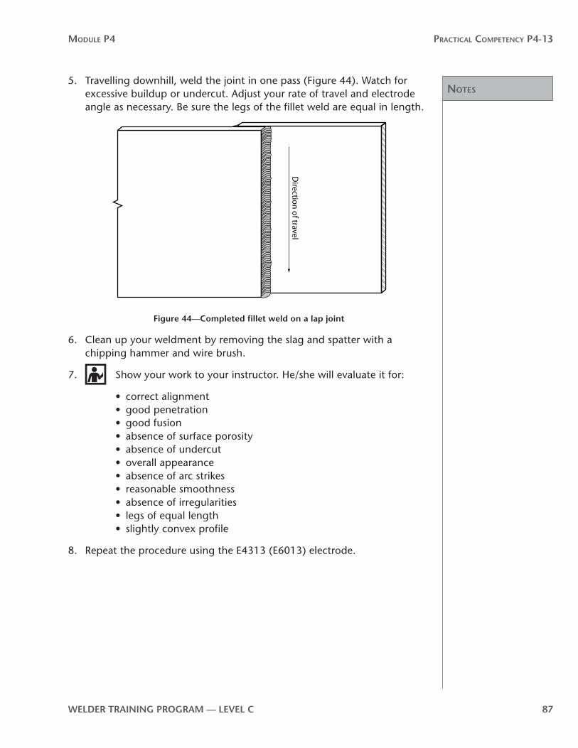
5. Travelling downhill, weld the joint in one pass (Figure 44). Watch for excessive buildup or undercut. Adjust your rate of travel and electrode angle as necessary. Be sure the legs of the fillet weld are equal in length.
Direction of travel
Figure 44—Completed fillet weld on a lap joint
6. Clean up your weldment by removing the slag and spatter with a chipping hammer and wire brush.
7. Show your work to your instructor. He/she will evaluate it for:
• correct alignment• good penetration• good fusion• absence of surface porosity• absence of undercut• overall appearance• absence of arc strikes• reasonable smoothness• absence of irregularities• legs of equal length• slightly convex profile
8. Repeat the procedure using the E4313 (E6013) electrode.

notes
Module P4 Practical coMPetency P4-13
88 WelDer TrAInInG PrOGrAM — level C
WPS P4-13-2B:Single-pass fillet welds on tee joints in the 3F downhill position
Materials
Base metal
10 gauge low-carbon steel sheet, minimum 25 mm × 200 mm (1" × 8")
Filler metal Polarity
E4310/4311 (E6010/E6011), 3.2 mm (1⁄8") diameter DCEP
E4313 (E6013), 3.2 mm (1⁄8") diameter DCEN
Welding symbol
SMAW
Directions
1. Position two pieces of low-carbon steel sheet to form a tee joint. Set the vertical piece 13 mm (½ in.) in from the edge of the bottom sheet. Make sure that the bottom sheet lies flat on the work surface and the vertical sheet forms the tee at 90° to the bottom sheet. Align the ends of the joint so the sheets are flush with each other.
2. Select the correct polarity and current settings for the E4310/E4311 (E6010/E6011) electrode. Attach the ground clamp to your workpiece. Insert the electrode in the electrode holder.
3. Make four tack welds, 10 mm (3⁄8 in.) long, one at each end of the joint and another two on the opposite side of the joint.

notes
Module P4 Practical coMPetency P4-13
WelDer TrAInInG PrOGrAM — level C 89
4. Place the joint in the 3F position (Figure 45).
Figure 45—Tee joint in the 3F position
5. Travelling downhill, weld the joint completely in one pass (Figure 46). Watch for excessive buildup or undercut. Adjust your rate of travel and electrode angle as necessary. Be sure the legs of the fillet weld are equal in length.
Direction of travel
Figure 46—Completed fillet weld on a tee joint

notes
Module P4 Practical coMPetency P4-13
90 WelDer TrAInInG PrOGrAM — level C
6. Clean up your weldment by removing the slag and spatter with a chipping hammer and wire brush.
7. Show your work to your instructor. He/she will evaluate it for:
• correct alignment• good penetration• good fusion• absence of surface porosity• absence of undercut• overall appearance• absence of arc strikes• reasonable smoothness• absence of irregularities• legs of equal length• slightly convex profile
8. Repeat the procedure using the E4313 (E6013) electrode.

Practical comPetency P4-14:Hardface in the flat position on low-carbon steel plate
P4
-14


WelDer TrAInInG PrOGrAM — level C 93
Module P4 Practical coMPetency P4-14
OutcomesHardfacing is important in industries where machinery and equipment are subjected to extreme wear, corrosion or high-temperature erosion. Hardfacing can be deposited using the following processes:
• oxy-fuel gas welding (OFW)• shielded metal arc welding (SMAW)• gas tungsten arc welding (GTAW)• submerged arc welding (SAW)• flux-cored arc welding (FCAW)• metal-cored arc welding (MCAW)
When you have completed Practical Competency P4-14, you will be able to:
• build up low-carbon steel plate in the flat position• hardface low-carbon steel plate in the flat position
evaluationYou will be required to do the following:
• build up low-carbon steel plate in the flat position• hardface low-carbon steel plate in the flat position
Your instructor will evaluate your ability at each step.
MaterialsEach Learning Task procedure identifies the materials and tools you will need to complete the assigned task. Your instructor will arrange for these tools and materials to be available to you.
Opti onal: The following resources are optional and are NOT required to complete this Practical Competency. The optional resources provide further information on a specific topic. If you want more information on these resources, please see your instructor.
Hardfacing Guide• http://content.lincolnelectric.com/pdfs/products/literature/c7710.pdf
WARNING!
If a Practical Competency procedure requires that you use a tool or piece of equipment that you have not previously operated—or you feel unsure about the operation of any tools or equipment—ask your instructor to demonstrate the correct procedures for the tool or piece of equipment before you use it.

94 WelDer TrAInInG PrOGrAM — level C
Module P4 Practical coMPetency P4-14
Use of materialsWelding is a very expensive trade. The cost of steel, filler metal and other consumables can rise or fall, depending on the marketplace. The only area in which there can be significant potential savings is in how we use steel. Steel is the largest single consumable cost. This is true in both training and industry.
Training institutions often have to buy scrap material to practise on. Therefore, steel used for practise might not be the exact size or thickness laid out in the Practical Competencies. This will not affect your learning. In fact, it might even better reflect the reality of the real welding world, where it is common practise to substitute material sizes.
When cutting new steel or steel crops, always strive for maximum use and minimum waste. Cut pieces from one end of plate so as to leave the largest possible area untouched for later use. Assemble lap joints and tee joints in a way that will reduce waste and maximize the size of off-cuts after welding.
General procedures for all welding Practical Competencies1. Arrange with your instructor for a demonstration of all procedures and for the
equipment you will need.
2. Follow all safety precautions, wear all personal protective clothing and use all personal protective equipment. Review P1-2: Use safe work practises.
3. Clean the base metal, if necessary. Remove any rust, mill scale or paint.
4. You will be required to repeat procedures until you receive an acceptable evaluation from your instructor.

notes
Module P4 Practical coMPetency P4-14
WelDer TrAInInG PrOGrAM — level C 95
P4-14 learning Task 1:Build up and hardface low-carbon steel plate in the flat positionTo complete this Learning Task, you must perform the following procedures:
• Procedure 1A: Build up low-carbon steel plate in the flat position
• Procedure 1B: Hardface a waffle pattern on low-carbon steel plate in the flat position
• Procedure 1C: Hardface a button pattern on low-carbon steel plate in the flat position

notes
Module P4 Practical coMPetency P4-14
96 WelDer TrAInInG PrOGrAM — level C
WPS P4-14-1A:Build up low-carbon steel plate in the flat position
Materials
Base metal
One piece of low-carbon steel from shop scrap 10 mm × 150 mm × 300 mm (3⁄8" × 6" × 12")
Filler metal Polarity
E4918 (E7018), 4 mm (5⁄32") diameter DCEP
(an alloy build up electrode can be substituted)
Welding symbol
SMAW
Directions
1. Select a weldment from the shop scrap and show it to your instructor for instructions before proceeding.
2. Select the correct polarity and current settings for the E4918 (E7018) electrode. Attach the ground clamp to your workpiece. Insert the electrode in the electrode holder.
3. Position your workpiece so that you will be welding in the flat position.
4. Weld your first bead along either short edge of the plate. Adjust your rate of travel and electrode angle as necessary. Be sure the weld is straight and consistent in width. Bead width should be 25 mm (1 in.).
5. Leaving a space of about 13 mm (1⁄2 in.), apply your next bead. Continue running beads about 13 mm (1⁄2 in.) apart until you reach the opposite end of the plate (Figure 47). It is good practise to use your combination square and soapstone to lay out lines for you to follow. These lines will act as a guide so your beads are straight and evenly spaced.

notes
Module P4 Practical coMPetency P4-14
WelDer TrAInInG PrOGrAM — level C 97
25 mm (1")
13 mm (½")
Figure 47—Beads with 13 mm (1⁄2 in ) spacing
6. Apply beads between the beads you ran in step 5. Continue until the entire surface of the plate is built up (Figure 48).
Figure 48—entire surface built up
7. Clean up your weldment by removing the slag and spatter with a chipping hammer and wire brush.
8. Show your work to your instructor. He/she will evaluate it for:
• correct alignment• good penetration• good fusion• absence of porosity• absence of undercut• overall appearance
• absence of arc strikes• reasonable smoothness• absence of irregularities• maximum buildup of 3 mm (1⁄8 in.)• slightly convex profile

notes
Module P4 Practical coMPetency P4-14
98 WelDer TrAInInG PrOGrAM — level C
WPS P4-14-1B:Hardface a waffle pattern on low-carbon steel plate in the flat position
Materials
Base metal
Plate used for buildup in Procedure 1A (WPS: P4-14-1A)
Filler metal Polarity
EFeMn-A, 3.2 mm (1⁄8") diameter (Your instructor might substitute another electrode)
Refer to electrode specification
Welding symbol
SMAW
Directions
1. Use a soapstone to lay out a waffle pattern for weld beads. Use 25 mm (1 in.) to 75 mm (3 in.) squares or as specified by your instructor.
2. Select the correct polarity and current settings for the electrode you will be using. Attach the ground clamp to your workpiece. Insert the electrode in the electrode holder.
3. Position your workpiece so that you will be welding in the flat position.
4. Weld stringer beads following your waffle pattern (Figure 49).
(1–3")25–75 mm
Figure 49—Weld stringer beads

Notes
Module P4 Practical coMPetency P4-14
WelDer TrAInInG PrOGrAM — level C 99
5. Clean up your weldment by removing the slag and spatter with a chipping hammer and wire brush.
6. Show your work to your instructor. He/she will evaluate it for:
• correct alignment• good penetration• good fusion• absence of porosity• absence of undercut• overall appearance• absence of arc strikes• reasonable smoothness• absence of irregularities• maximum buildup of 3 mm (1⁄8 in.)• slightly convex profile

Notes
Module P4 Practical coMPetency P4-14
100 WelDer TrAInInG PrOGrAM — level C
WPS P4-14-1C:Hardface a button pattern on low-carbon steel plate in the flat position
Materials
Base metal
Opposite side of plate used in Procedures 1A and 1B (WPS: P4-14-1A & 1B)
Filler metal Polarity
EFeMn-A, 3.2 mm (1⁄8") diameter (Your instructor might substitute another electrode)
Refer to electrode specification
Welding symbol
SMAW
Directions
1. Use a soapstone to lay out the centre points of a button pattern as specified by your instructor on the back surface of the plate you used in Procedures 1A and 1B. Your pattern should be staggered and spaced to allow for buttons 16 mm (5⁄8 in.) to 25 mm (1 in.) in diameter.
2. Select the correct polarity and current setting for the electrode you will be using. Attach the ground clamp to your workpiece. Insert the electrode in the electrode holder.
3. Position your workpiece so that you will be welding in the flat position.
4. Following your pattern, weld buttons until all of the centre points are covered (Figure 50). Buttons welds should be deposited by circling the centre points until the button reaches the desired size.
Figure 50—Staggered pattern of deposits

Notes
Module P4 Practical coMPetency P4-14
WelDer TrAInInG PrOGrAM — level C 101
5. Clean up your weldment by removing the slag and spatter with a chipping hammer and wire brush.
6. Show your work to your instructor. He/she will evaluate it for:
• absence of arc strikes• reasonable smoothness• good fusion• absence of irregularities• absence of porosity• overall appearance

notes
Module P4 Practical coMPetency P4-14
102 WelDer TrAInInG PrOGrAM — level C

Practical comPetency P4-15:Groove welds on grey cast iron in the flat (1G) position
P4
-15


WelDer TrAInInG PrOGrAM — level C 105
Module P4 Practical coMPetency P4-15
OutcomesGrey cast iron has special characteristics that require procedures different from those for welding low-carbon steel.
When you have completed Practical Competency P4-15, you will be able to:
• weld groove welds in the 1G position using a single vee butt joint on grey cast iron
evaluationYou will be required to successfully do the following:
• weld groove welds in the 1G position using a single vee butt joint on grey cast iron
Your instructor will evaluate your ability at each step.
MaterialsEach Learning Task procedure identifies the materials and tools you will need to complete the assigned task. Your instructor will arrange for these tools and materials to be available to you.
Optional: The following resources are optional and are NOT required to complete this Practical Competency. The optional resources provide further information on a specific topic. If you want more information on these resources, please see your instructor.
Guidelines on welding cast iron:• http://www.lincolnelectric.com/knowledge/articles/content/castironpreheat.asp
WARNING!
If a Practical Competency procedure requires that you use a tool or piece of equipment that you have not previously operated—or you feel unsure about the operation of any tools or equipment—ask your instructor to demonstrate the correct procedures for the tool or piece of equipment before you use it.
Use of materialsWelding is a very expensive trade. The cost of steel, filler metal and other consumables can rise or fall, depending on the marketplace. The only area in which there can be significant potential savings is in how we use steel. Steel is the largest single consumable cost. This is true in both training and industry.

106 WelDer TrAInInG PrOGrAM — level C
Module P4 Practical coMPetency P4-15
Training institutions often have to buy scrap material to practise on. Therefore, steel used for practise might not be the exact size or thickness laid out in the Practical Competencies. This will not affect your learning. In fact, it might even better reflect the reality of the real welding world, where it is common practise to substitute material sizes.
When cutting new steel or steel crops, always strive for maximum use and minimum waste. Cut pieces from one end of plate so as to leave the largest possible area untouched for later use. Assemble lap joints and tee joints in a way that will reduce waste and maximize the size of off-cuts after welding.
General procedures for all welding Practical Competencies1. Arrange with your instructor for a demonstration of all procedures and for the
equipment you will need.
2. Follow all safety precautions, wear all personal protective clothing and use all personal protective equipment. Review P1-2: Use Safe Work Practises.
3. Clean the base metal, if necessary. Remove any rust, mill scale or paint.
4. You will be required to repeat procedures until you receive an acceptable evaluation from your instructor.

notes
Module P4 Practical coMPetency P4-15
WelDer TrAInInG PrOGrAM — level C 107
P4-15 learning Task 1:Groove welds on grey cast iron in the flat (1G) positionTo complete this Learning Task, you must perform the following welding procedure:
• Groove welds using a single vee butt joint on grey cast iron in the 1G position

notes
Module P4 Practical coMPetency P4-15
108 WelDer TrAInInG PrOGrAM — level C
WPS P4-15-1:Single vee butt joint on grey cast iron in the 1G position
Materials
Base metal
Any grey cast iron casting such as a bracket or engine part with a fracture, or one that can be intentionally fractured or broken for the exercise
Filler metal Polarity
ENICI, 3.2 mm (1⁄8") diameter AC, DCEP or DCEN (Refer to electrode specification)
note: Joint dimensions are suggestions only. Check with your instructor for the availability of materials, the dimensions and the joint configuration that will be appropriate.
Welding symbol
SMAW2.5
60–90º
Instructions1. Carefully clean the grey cast iron. Make sure you remove all oil, grease,
dirt, oxides and burrs.
2. Bevel the fracture line for a single vee butt joint. Leave about 2 mm (1⁄16 in. to 3⁄32 in.) of the fracture line so that the pieces can be fitted back into their original positions. Trial-fit the pieces and set them up on a firebrick or insulated support.
If the pieces are difficult to fit together and locate, design a backing plate to bolt the parts to or arrange some form of clamping system to hold the parts in position.
3. Select the correct polarity and current settings for the electrode. Use a current setting in the lower end of the recommended range.
4. Preheat the casting to 300 °C (580 °F). Check the temperature using a “Tempil” stick or a hand-held infrared temperature sensor.
Hot Tip! 260 °C to 650 °C (500 ºF to 1200 ºF) is the recommended range. Do not go higher than 700 ºC (1300 ºF). Above this temperature the casting undergoes molecular structural changes, changing from body-centred cubic to face-centred cubic.

notes
Module P4 Practical coMPetency P4-15
WelDer TrAInInG PrOGrAM — level C 109
5. Attach the ground clamp to your workpiece. Insert the electrode in the electrode holder.
6. Make two tack welds 13 mm (1⁄2 in.) long, one at each end of the joint.
7. Weld your first bead segment, about 13 mm (1⁄2 in.) long. Then chip off the slag and immediately peen this segment. Apply the next 13 mm (1⁄2 in.) segment, chip off the slag and peen.
Hot Tip! Separate the deposits from each other by using a skip or back-step sequence. This will help avoid a buildup of heat in any one area. Maintain a maximum reinforcement of 2.5 mm (3⁄32 in.).
8. Continue applying short welds and immediately peening until the complete joint is welded. Avoid any interruptions or delays in welding, because the preheat temperature must be maintained until the weld is complete.
9. Turn the piece over and quickly score the back side of the joint with a grinder. Weld up that side with a small seal bead. Separate the deposits from each other by using a skip or back-step sequence and immediately peen each bead.
10. Post-heat the casting to your preheat temperatures to ensure that the heat is even. Then cover and let cool as slowly as possible.
11. When the casting is cool, uncover it and clean up your weldment by removing any slag or spatter with a chipping hammer and wire brush. Grind off any part of the weld bead that would interfere when the casting is put back in service.
12. Show your work to your instructor. He/she will evaluate it for:
• correct alignment• absence of arc strikes• absence of distortion• overall appearance• smoothness• absence of irregularities• correct reinforcement

notes
Module P4 Practical coMPetency P4-15
110 WelDer TrAInInG PrOGrAM — level C

Practical comPetency P4-16:Stainless steel welds on low-carbon steel plate
P4
-16


WelDer TrAInInG PrOGrAM — level C 113
Module P4 Practical coMPetency P4-16
OutcomesWhen you have completed Practical Competency P4-16, you will be able to:
• weld multi-pass welds in the 2F position using stainless steel filler alloys
evaluationYou will be required to successfully do the following:
• weld multi-pass fillet welds on low-carbon steel plate in the horizontal (2F) position using stainless steel electrodes
Your instructor will evaluate your ability at each step.
resourcesOptional: The following resources are optional and are NOT required to complete this Practical Competency. The optional resources provide further information on a specific topic. If you want more information on these resources, please see your instructor.
Properties of stainless steels:• http://content.lincolnelectric.com/pdfs/products/literature/c64000.pdf
MaterialsEach Learning Task procedure identifies the materials and tools you will need to complete the assigned task. Your instructor will arrange for these tools and materials to be available to you.
WARNING!
If a Practical Competency procedure requires that you use a tool or piece of equipment that you have not previously operated—or you feel unsure about the operation of any tools or equipment—ask your instructor to demonstrate the correct procedures for the tool or piece of equipment before you use it.
Use of materialsWelding is a very expensive trade. The cost of steel, filler metal and other consumables can rise or fall, depending on the marketplace. The only area in which there can be significant potential savings is in how we use steel. Steel is the largest single consumable cost. This is true in both training and industry.
Training institutions often have to buy scrap material to practise on. Therefore, steel used for practise might not be the exact size or thickness laid out in the Practical Competencies. This will not affect your learning. In fact, it might even better reflect the reality of the real welding world, where it is common practise to substitute material sizes.
When cutting new steel or steel crops, always strive for maximum use and minimum waste. Cut pieces from one end of plate so as to leave the largest possible area

114 WelDer TrAInInG PrOGrAM — level C
Module P4 Practical coMPetency P4-16
untouched for later use. Assemble lap joints and tee joints in a way that will reduce waste and maximize the size of off-cuts after welding.
General procedures for all welding Practical Competencies1. Arrange with your instructor for a demonstration of all procedures and for the
equipment you will need.
2. Follow all safety precautions, wear all personal protective clothing and use all personal protective equipment. Review P1-2: Use Safe Work Practises.
3. Clean the base metal, if necessary. Remove any rust, mill scale or paint.
4. You will be required to repeat procedures until you receive an acceptable evaluation from your instructor.

Notes
Module P4 Practical coMPetency P4-16
WelDer TrAInInG PrOGrAM — level C 115
P4-16 learning Task 1:Multi-pass fillet welds on tee joints in the horizontal (2F) position using stainless steel electrodesTo complete this Learning Task, you must perform the following:
• Weld multi-pass fillet welds on low-carbon steel plate in the horizontal position using stainless steel electrodes

notes
Module P4 Practical coMPetency P4-16
116 WelDer TrAInInG PrOGrAM — level C
WPS P4-16-1:Multi-pass fillet welds on tee joints in the 2F position
Materials
Base metal
Two pieces of low-carbon steel plate 10 mm or 13 mm (3⁄8" or 1⁄2") thickby 200 mm (8") wide
Filler metal Polarity
E309, 3 mm (1⁄8") diameter (E304, E308 or E316 can be substituted)
AC or DCEP
Welding symbol
SMAW
CAUTION!
The slag from stainless steel welds will fly off violently while still hot. This can cause severe burns to the skin or permanent damage to unprotected eyes.

notes
Module P4 Practical coMPetency P4-16
WelDer TrAInInG PrOGrAM — level C 117
Directions
1. Position your two plates to make a tee joint. Set the vertical piece two thicknesses in from the edge of the bottom plate. Make sure that the bottom plate lies flat on the work surface and the vertical plate forms the tee at 90° to the bottom plate (Figure 51). Align the ends of the joint so the plates are flush with each other.
90º
Figure 51—Tee joint plate alignment
2. Select the correct polarity and current settings for the electrode.
3. Make four tack welds 19 mm (3⁄4 in.) long, one at each end of the joint and another two on the opposite side of the joint (Figure 52).
Tack welds90º
Figure 52—Tee joint tack welds

notes
Module P4 Practical coMPetency P4-16
118 WelDer TrAInInG PrOGrAM — level C
4. Place the tee joint in the 2F position (Figure 53).
5. Weld the tee joint (Figure 53). Watch for excessive buildup or undercut. Adjust the rate of travel and electrode angle as necessary. Be sure the legs of the fillet weld are equal in length.
6
4
2 1
3
5
Figure 53—Completed multi-pass fillet weld on a tee joint in the 2F position
6. Clean up your weldment by removing the slag and spatter with a chipping hammer and wire brush.
7. Show your work to your instructor. He/she will evaluate it for:
• correct alignment• good penetration• reasonable smoothness• legs of equal length• absence of undercut• overall appearance• absence of arc strikes• absence of irregularities• slightly convex profile• absence of porosity
Practical comPetency P4-17:Groove welds on low-carbon steel plate
P4
-17


WelDer TrAInInG PrOGrAM — level C 121
Module P4 Practical coMPetency P4-17
OutcomesWhen you have completed Practical Competency P4-17, you will be able to:
• use a Welding Procedure Specification (WPS)
• weld a single vee butt joint with open root in the 1G position
• weld single bevel butt joints with backing in the 1GF, 2GF, 3GF uphill and 4GF positions
• successfully complete root and face-bend tests on groove welds
evaluationYou will be required to do the following:
• use a Welding Procedure Specification (WPS)
• weld a single vee butt joint with open root in the 1G position and pass a bend test on your weld
• weld single bevel butt joints with backing in the 1GF, 2GF, 3GF uphill and 4GF positions and successfully complete bend tests on your welds
Your instructor will evaluate your ability at each step. Your test coupons must pass the bend tests.
MaterialsEach Learning Task procedure identifies the materials and tools you will need to complete the assigned task. Your instructor will arrange for these tools and materials to be available to you.
WARNING!
If a Practical Competency procedure requires that you use a tool or piece of equipment that you have not previously operated—or you feel unsure about the operation of any tools or equipment—ask your instructor to demonstrate the correct procedures for the tool or piece of equipment before you use it.
Use of materialsWelding is a very expensive trade. The cost of steel, filler metal and other consumables can rise or fall, depending on the marketplace. The only area in which there can be significant potential savings is in how we use steel. Steel is the largest single consumable cost. This is true in both training and industry.
Training institutions often have to buy scrap material to practise on. Therefore, steel used for practise might not be the exact size or thickness laid out in the Practical Competencies. This will not affect your learning. In fact, it might even better reflect the reality of the real welding world, where it is common practise to substitute material sizes.

122 WelDer TrAInInG PrOGrAM — level C
Module P4 Practical coMPetency P4-17
When cutting new steel or steel crops, always strive for maximum use and minimum waste. Cut pieces from one end of plate so as to leave the largest possible area untouched for later use. Assemble lap joints and tee joints in a way that will reduce waste and maximize the size of off-cuts after welding.
General procedures for all welding Practical Competencies1. Arrange with your instructor for a demonstration of all procedures and for the
equipment you will need.
2. Follow all safety precautions, wear all personal protective clothing and use all personal protective equipment. Review P1-2: Use Safe Work Practises.
3. Clean the base metal, if necessary. Remove any rust, mill scale or paint.
4. You will be required to repeat procedures until you receive an acceptable evaluation from your instructor.

Notes
Module P4 Practical coMPetency P4-17
WelDer TrAInInG PrOGrAM — level C 123
P4-17 learning Task 1:Functions of a welding procedure specification (WPS)
Welding Procedure Specification (WPS)Some welding shops are certified by governing bodies that set standards in weld quality. This is done so that engineers and customers know that the Welders and their welds will meet a set standard of quality. Many shops are certified under the Canadian Welding Bureau (CWB) or the American Society of Mechanical Engineers (ASME). There are also shops certified for building ships, aircraft, railroad equipment and petrochemical equipment.
Welding and fabrication shops that are CWB certified often construct components of large structures that have to be built to design code. ASME-certified shops often build pressure vessels, piping systems and boilers. In both cases, faulty welds could have lethal results. Having a system of weld procedures that have been proven to meet code ensures that they will produce a safe product for the customer and end user.
At first your Practical Competencies will provide you with a step-by-step procedure to follow. Gradually, you will encounter simplified versions of a Welding Procedure Specification (WPS) data sheet in your Practical Competencies. This will help you become familiar with the format.
Eventually you will be able to read a one- or two-page WPS data sheet and understand what has to be done to make a quality weld. A WPS gives you all the information you require in an abbreviated form. The following is a sample WPS with descriptions of the information it contains.

Notes
Module P4 Practical coMPetency P4-17
124 WelDer TrAInInG PrOGrAM — level C
Sample Welding Procedure Specification
Welding Procedure Specification (WPS): This identifies the procedure by number and/or name, etc.
Position: This gives the position of the weld, such as flat, horizontal, vertical up or overhead. Depending on joint design, the position can be expressed as 1F, 1G, 2F, 2G, etc.
Process: This area gives the type of welding process to be used, such as SMAW, GMAW or SAW.
Joint Design and Tolerance: A diagram will be placed here illustrating the joint design. It might include welding symbols to identify the size and location of the weld.
Suggested Sequence: A diagram illustrating more information is often placed here to show details of the weld sequence if necessary.
Base Metal: The base metal type, grade, specification and thickness are identified here. Often in industry the exact alloy can be very important.
Filler Metal: The electrode or filler metal specification is listed here. Filler metal can be identified by its classification number (e.g. E4310, E4918, etc.) or by its group number (e.g. F1, F2, F3, etc.).
Diameter of electrode: Normally identifies a range of electrode diameters that can be used.
Shielding: The type of shielding to be used if required. It may be a gas or loose flux.
Welding notes: Special instructions regarding size, placement of tack welds, motions or length of arc, wire feed rates, welding speed, etc., are listed here.
electrical Characteristics: This could include polarity, amperage, voltage, etc.
Directions: Additional information, step-by-step instructions, diagrams or anything else to make sure the Welder understands and is able to produce the required weld. Information could include:
1. preheating and post-heating temperatures and procedures
2. pre- and post-weld and weldment cleaning processes and procedures
3. methods of joint preparation

Notes
Module P4 Practical coMPetency P4-17
WelDer TrAInInG PrOGrAM — level C 125
P4-17 learning Task 2:Single vee butt joint with open root in the 1G position on low-carbon steel plateTo complete this Learning Task, you must perform the following procedures:
• Procedure A: Prepare and weld single vee butt joints
• Procedure B: Prepare face- and root-bend test coupons for a single vee butt joint

Notes
Module P4 Practical coMPetency P4-17
126 WelDer TrAInInG PrOGrAM — level C
Welding Procedure Specification (WPS): P4-17-2A
Position: 1G Process: SMAW
Joint Design and Tolerance: Suggested Sequence:
2.5 ± 0.8
60º
2.5 ± 0.8
Base Metal: CSA G 40.21 GR 44W/A36 2 pieces: 10 mm or 13 mm × 75 mm × 200 mm (3⁄8" or 1⁄2" × 3" × 8")
Filler Metal: F3: E4310/E4311 (E6010/E6011) rootF4: E4918 (E7018) fill
Diameter of electrode: F3: 3.2 mm (1⁄8") F4: 3.2 mm (1⁄8")
Shielding:NA
Welding notes:
1. Check bevel angle and root face with a drill point bevel gauge.
2. One root-bend coupon must contain a stop-start in the root weld.
3. Filler and cover passes are weave beads.
electrical Characteristics: F3: DCEP, 80–90 AF4: DCEP, 120–140 A
Directions:
1. Arrange with your instructor for a demonstration of this procedure.
2. Prepare the edges of the joint as shown above.
3. Follow the steps below to place two tack welds on the back of the plate, one at each end of the joint (Figure 54):
• Fit with one end set at a 2.5 mm to 3.2 mm (3⁄32" to 1⁄8") gap and the other end touching.
• Tack weld the gapped end with a 13 mm (1⁄2") tack.
• Adjust the gap at the opposite end, then tack weld.
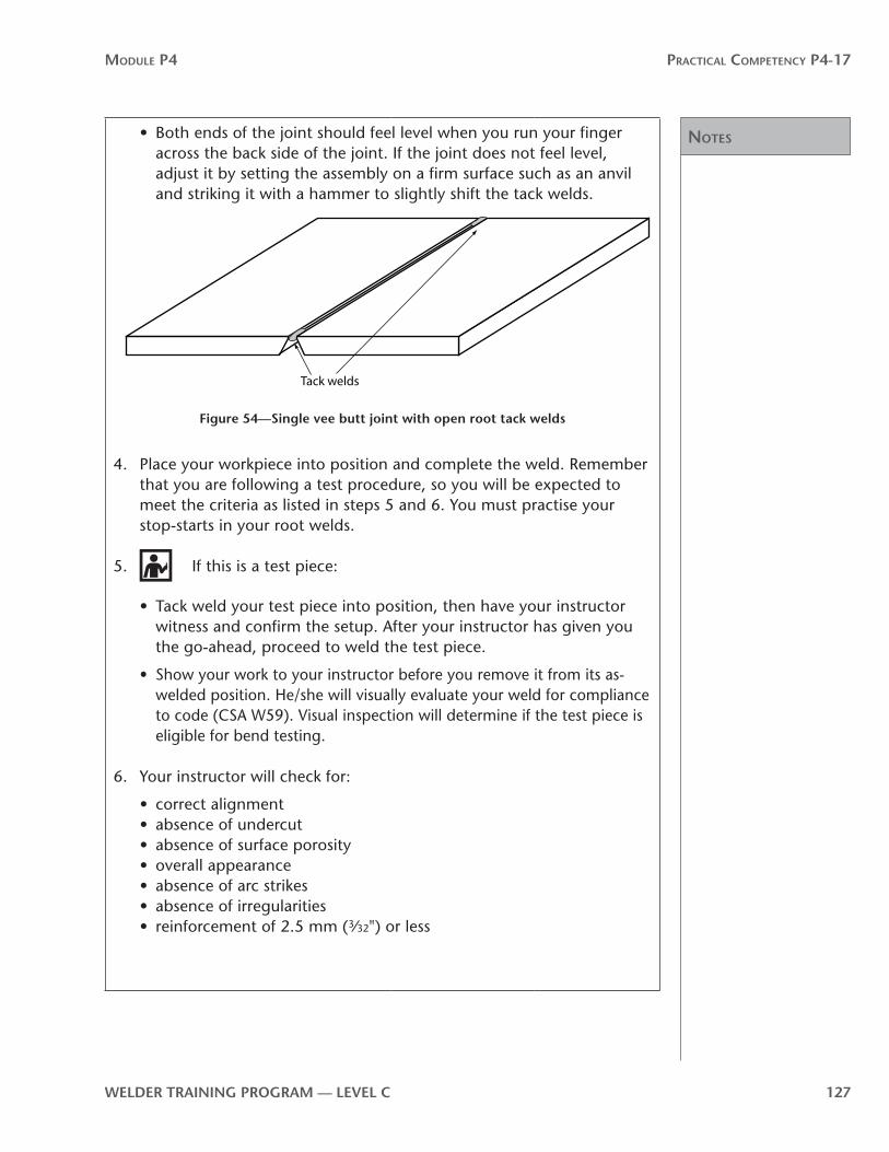
notes
Module P4 Practical coMPetency P4-17
WelDer TrAInInG PrOGrAM — level C 127
• Both ends of the joint should feel level when you run your finger across the back side of the joint. If the joint does not feel level, adjust it by setting the assembly on a firm surface such as an anvil and striking it with a hammer to slightly shift the tack welds.
Tack welds
Figure 54—Single vee butt joint with open root tack welds
4. Place your workpiece into position and complete the weld. Remember that you are following a test procedure, so you will be expected to meet the criteria as listed in steps 5 and 6. You must practise your stop-starts in your root welds.
5. If this is a test piece:
• Tack weld your test piece into position, then have your instructor witness and confirm the setup. After your instructor has given you the go-ahead, proceed to weld the test piece.
• Show your work to your instructor before you remove it from its as-welded position. He/she will visually evaluate your weld for compliance to code (CSA W59). Visual inspection will determine if the test piece is eligible for bend testing.
6. Your instructor will check for:
• correct alignment• absence of undercut• absence of surface porosity• overall appearance• absence of arc strikes• absence of irregularities• reinforcement of 2.5 mm (3⁄32") or less

notes
Module P4 Practical coMPetency P4-17
128 WelDer TrAInInG PrOGrAM — level C
WPS P4-17-2B:Prepare face- and root-bend test coupons for a single vee butt jointTools and equipment
• combination square• soapstone• number/letter stamps• hammer• grinder• guided bend jig• oxy-fuel cutting equipment
Materials
• Welded test plate from Practical Competency P4-17-2A.
Directions
1. Study Figure 55 to see how to lay out and identify coupons for face- and root-bend tests.
2. Using a combination square and soapstone, lay out four 38 mm (11⁄2 in.) coupons. Don’t forget to allow for the kerf.
3. Using the number and letter stamps, identify (Figure 55) each coupon with:
• your initials• weld position (1G)• bend test orientation (“F” for face bend and “R” for root bend)
Discard
Discard
150 mm
38 mm
Welder’s initialsWeld position
PH 1G F
Root
Face
Face
Root
Bend
Bend
Bend
Bend
Test specimen layout Test coupon layout
Root/face bend (R/F)
Figure 55—laying out and identifying coupons
4. Using oxy-fuel cutting equipment, cut the 38 mm (11⁄2 in.) coupons from the weldment. You will have a total of four coupons.

notes
Module P4 Practical coMPetency P4-17
WelDer TrAInInG PrOGrAM — level C 129
5. On each coupon:
• Finish-grind the face and root weld reinforcement. Make them flush with the surface.
• Dress the weld area of the coupon with a grinder, if necessary.
• Polish the tension side and edges of the coupon. For the root-bend coupons, polish the root side of the coupon. For the face-bend coupons, polish the face side of the coupon. You only need to polish 100 mm (4 in.) of the coupon, with your weld centred in the polished area.
• Radius the corners along the longitudinal edges to 1.6 mm (1⁄16 in.).
6. Your instructor will bend your coupons, polished side down, in the guided-bend jig (Figure 56). Your coupons will take the shape of the die as they are bent.
Punch(Plunger)
Coupon
Die
Figure 56—Guided-bend jig
7. Your instructor will evaluate your coupons in accordance with CSA W59 or Section IX of the ASME code specifications, as follows:
• The weld and heat-affected zone of a transverse weld-bend specimen shall be completely within the bent portion of the specimen after testing.
• The guided-bend specimens shall have no open discontinuities in the weld or heat-affected zone exceeding 3.2 mm (1⁄8 in.) measured in any direction on the convex surface of the specimen after bending.
• Cracks occurring on the corners of the specimen during testing shall not be considered unless there is definite evidence that they result from slag inclusions or other internal discontinuities.
You must repeat the welding procedure until your weld passes the face- and root-bend tests in accordance with the specifications.

notes
Module P4 Practical coMPetency P4-17
130 WelDer TrAInInG PrOGrAM — level C

notes
Module P4 Practical coMPetency P4-17
WelDer TrAInInG PrOGrAM — level C 131
P4-17 learning Task 3:Single bevel butt joint with backing in the 1GF position on low-carbon steel plateTo complete this Learning Task, you must perform the following procedures:
• Procedure A: Prepare and weld single bevel butt joints with backing
• Procedure B: Prepare face- and root-bend test coupons for a single bevel butt joints with backing

Notes
Module P4 Practical coMPetency P4-17
132 WelDer TrAInInG PrOGrAM — level C
Welding Procedure Specification (WPS): P4-17-3A
Position: 1GF Process: SMAW
Joint Design and Tolerance: Suggested Sequence:
30º
13 mm
Fillet weld Groove welds
Base Metal: CSA G 40.21 GR 44W/A36
2 pieces: 10 mm or 13 mm × 75 mm × 200 mm (3⁄8" or 1⁄2" × 3" × 8") 1 piece: 6.4 mm × 32 mm (1⁄4" × 11⁄4") flat bar, 230 mm (9") long
Filler Metal: F4: E4918 (E7018)
Diameter of electrode: F4: 3.2 mm (1⁄8")
Shielding: NA
Welding notes:
1. Check bevel angle and plate spacing with a drill point bevel gauge.
2. Fillet weld maximum size is 8 mm (5⁄16").
3. One root-bend coupon must contain a stop-start in the root fillet weld.
4. Cover pass can be a single weave bead or two stringer beads.
electrical Characteristics:F4: DCEP 120–140 A
Directions:
1. Arrange with your instructor for a demonstration of this procedure.
2. Prepare the edges of the joint as shown above.
3. Follow the steps below to place tack welds:
• Set the plates the required distance apart as per the WPS and tack weld at both sides of each end (4 tack welds) of the backing flat bar.
• Make sure that the plates sit tight against the backing flat bar with no gaps. You might want to use clamps to ensure a tight fit.

Notes
Module P4 Practical coMPetency P4-17
WelDer TrAInInG PrOGrAM — level C 133
Welding Procedure Specification (WPS): P4-17-3A
4. Place your workpiece into position and complete the weld. Remember that you are following a test procedure, so you will be expected to meet the criteria as listed in steps 5 and 6. You must practise your stop-starts in your fillet weld.
5. If this is a test piece:
• Tack weld your test pieces together, then have your instructor metal stamp the locations of your root and face bends, and your fillet weld and groove weld stop-starts.
• Tack weld your test piece into position, then have your instructor witness and confirm the setup. After your instructor has given you the go-ahead, proceed to weld the test piece.
• Weld your fillet weld to the stop-start mark. Have your instructor inspect the weld. After your instructor has given you the go-ahead, proceed to weld the rest of the fillet weld.
• Starting from the same end, weld the groove weld to the stop-start mark. Have your instructor inspect the weld. After your instructor has given you the go-ahead, proceed to weld the rest of the test piece.
• Show your work to your instructor before you remove it from its as-welded position. He/she will visually evaluate your weld for compliance to code (CSA W59). Visual inspection will determine if the test piece is eligible for bend testing.
6. Your instructor will check for:
• correct alignment• absence of undercut• absence of surface porosity• overall appearance• absence of arc strikes• absence of irregularities• reinforcement of 2.5 mm (3⁄32") or less

Notes
Module P4 Practical coMPetency P4-17
134 WelDer TrAInInG PrOGrAM — level C
WPS P4-17-3B:Prepare face- and root-bend test coupons for a single bevel butt jointTools and equipment
• combination square• soapstone• stamps• hammer• grinder• guided bend jig• oxy-fuel cutting equipment
Materials
• Welded test plate from Practical Competency P4-17-3A
Directions
1. Remove the backing bar from the back of your test piece using oxy-fuel or carbon arc gouging.
2. Rough-grind the back and the face (weld reinforcement). Make them almost flush with the surface.
3. Study Figure 57 to see how to lay out and identify coupons for face- and root-bend tests.
Discard
Discard
150 mm
38 mm
Welder’s initialsWeld position
PH1G
F
F
Root
Face
Face
Root
Bend
Bend
Bend
Bend
Test specimen layout Test coupon layout
Root/face bend (R/F)
Figure 57—laying out and identifying coupons
4. Using a combination square and soapstone, lay out four 38 mm (11⁄2 in.) coupons. Remember:
• Allow for the kerf.
• The two root-bend coupons must be cut from the stop-start locations that were previously stamped.

Notes
Module P4 Practical coMPetency P4-17
WelDer TrAInInG PrOGrAM — level C 135
5. Using the number and letter stamps, identify each coupon with:
• your initials• weld position (1GF)• bend test orientation (“F” for face bend and “R” for root bend)
6. Using oxy-fuel cutting equipment, cut the 38 mm (11⁄2 in.) coupons from the weldment. You will have a total of four coupons.
7. On each coupon:
• Finish-grind the face and root of each coupon. Make them flush with the surface.
• Dress the weld area of the coupons with a grinder, if necessary.
• Polish the tension side and edges of the coupons. For the root-bend coupons, polish the root side of the coupon. For the face-bend coupons, polish the face side of the coupon. You only need to polish 75 mm (3 in.) of the coupon, with your weld centred in the polished area.
• Radius the corners along the longitudinal edges to 1.6 mm (1⁄16 in.).
8. Your instructor will bend your coupons, polished side down, in the guided-bend jig. Your coupons will take the shape of the die as they are bent.
9. Your instructor will evaluate your coupons in accordance with CSA W59 or Section IX of the ASME code, as follows:
• The weld and heat-affected zone of a transverse weld-bend specimen shall be completely within the bent portion of the specimen after testing.
• The guided-bend specimens shall have no open discontinuities in the weld or heat-affected zone exceeding 3.2 mm (1⁄8 in.) measured in any direction on the convex surface of the specimen after bending
• Cracks occurring on the corners of the specimen during testing shall not be considered unless there is definite evidence that they result from slag inclusions or other internal discontinuities.
You must repeat the welding procedure until your weld passes the face- and root-bend tests in accordance with the specifications.

notes
Module P4 Practical coMPetency P4-17
136 WelDer TrAInInG PrOGrAM — level C

Notes
Module P4 Practical coMPetency P4-17
WelDer TrAInInG PrOGrAM — level C 137
P4-17 learning Task 4:Single bevel butt joint with backing in the 2GF position on low-carbon steel plateTo complete this Learning Task, you must perform the following procedures:
• Procedure A: Prepare and weld single bevel butt joints with backing
• Procedure B: Prepare face- and root-bend test coupons for a single bevel butt joints with backing

notes
Module P4 Practical coMPetency P4-17
138 WelDer TrAInInG PrOGrAM — level C
Welding Procedure Specification (WPS): P4-17-4A
Position: 2GF Process: SMAW
Joint Design and Tolerance:
30º8 mm
Suggested Sequence:
Fillet weld
Groove welds
Base Metal: CSA G 40.21 GR 44W/A36 2 pieces: 10 mm or 13 mm × 75 mm × 200 mm (3⁄8" or 1⁄2" × 3" × 8") 1 piece: 6.4 mm × 32 mm (1⁄4" × 11⁄4") flat bar, 230 mm (9") long
Filler Metal:F4: E4918 (E7018)
Diameter of electrode:F4: 3.2 mm (1⁄8")
Shielding:NA
Welding notes:
1. Check bevel angle and plate spacing with a drill point bevel gauge.
2. Fillet weld maximum size is 6 mm (1⁄4").
3. One root-bend coupon must contain a stop-start in the root fillet weld.
4. Cover pass is stringer beads.
electrical Characteristics: F4: DCEP 110–130 A
Directions:
1. Arrange with your instructor for a demonstration of this procedure.
2. Prepare the edges of the joint as shown above.
3. Follow the steps below to place tack welds:
• Set the plates the required distance apart as per the WPS and tack weld at both sides of each end (4 tack welds) of the backing flat bar.
• Make sure that the plates sit tight against the backing bar with no gaps. You may want to use clamps to ensure a tight fit.
Notes
Module P4 Practical coMPetency P4-17
WelDer TrAInInG PrOGrAM — level C 139
Welding Procedure Specification (WPS): P4-17-4A
4. Place your workpiece into position and complete the weld. Remember that you are following a test procedure, so you will be expected to meet the criteria as listed in steps 5 and 6. You must practise your stop-starts in your fillet weld.
5. If this is a test piece:
• Tack weld your test pieces together, then have your instructor metal stamp the locations of your root and face bends, and your fillet weld and groove weld stop-starts.
• Tack weld your test piece into position, then have your instructor witness and confirm the setup. After your instructor has given you the go-ahead, proceed to weld the test piece.
• Weld your fillet weld to the stop-start mark. Have your instructor inspect the weld. After your instructor has given you the go-ahead, proceed to weld the rest of the fillet weld.
• Starting from the same end, weld the groove weld to the stop-start mark. Have your instructor inspect the weld. After your instructor has given you the go-ahead, proceed to weld the rest of the test piece.
• Show your work to your instructor before you remove it from its as-welded position. He/she will visually evaluate your weld for compliance to code (CSA W59). Visual inspection will determine if the test piece is eligible for bend testing.
Your instructor will check for:
• correct alignment• absence of undercut• absence of surface porosity• overall appearance• absence of arc strikes• absence of irregularities• reinforcement of 2.5 mm (3⁄32") or less

Notes
Module P4 Practical coMPetency P4-17
140 WelDer TrAInInG PrOGrAM — level C
WPS P4-17-4B:Prepare face- and root-bend test coupons for a single bevel butt jointMaterials
• Welded test plate from Practical Competency P4-17-4A
Directions
1. Remove the backing bar from the back of your test piece using oxy-fuel or carbon arc gouging.
2. Rough-grind the back and the face (weld reinforcement). Make them almost flush with the surface.
3. Study Figure 58 to see how to lay out and identify coupons for face- and root-bend tests.
Discard
Discard
150 mm
38 mm
Welder’s initialsWeld position
PH2G
F
F
Root
Face
Face
Root
Bend
Bend
Bend
Bend
Test specimen layout Test coupon layout
Root/face bend (R/F)
Figure 58—laying out and identifying coupons
4. Using a combination square and soapstone, lay out four 38 mm (11⁄2 in.) coupons. Remember:
• Allow for the kerf.
• The two root-bend coupons must be cut from the stop-start locations that were previously stamped.
5. Using the number and letter stamps, identify each coupon with:
• your initials• weld position (2GF)• bend test orientation (“F” for face bend and “R” for root bend)
6. Using oxy-fuel cutting equipment, cut the 38 mm (11⁄2 in.) coupons from the weldment. You will have a total of four coupons.

Notes
Module P4 Practical coMPetency P4-17
WelDer TrAInInG PrOGrAM — level C 141
7. On each coupon:
• Finish-grind the face and root of each coupon. Make them flush with the surface.
• Dress the weld area of the coupons with a grinder, if necessary.
• Polish the tension side and edges of the coupons. For the root-bend coupons, polish the root side of the coupon. For the face-bend coupons, polish the face side of the coupon. You only need to polish 75 mm (3 in.) of the coupon, with your weld centred in the polished area.
• Radius the corners along the longitudinal edges to 1.6 mm (1⁄16 in.).
8. Your instructor will bend your coupons, polished side down, in the guided-bend jig. Your coupons will take the shape of the die as they are bent.
9. Your instructor will evaluate your coupons in accordance with CSA W59 or Section IX of the ASME code, as follows:
• The weld and heat-affected zone of a transverse weld-bend specimen shall be completely within the bent portion of the specimen after testing.
• The guided-bend specimens shall have no open discontinuities in the weld or heat-affected zone exceeding 3.2 mm (1⁄8 in.) measured in any direction on the convex surface of the specimen after bending.
• Cracks occurring on the corners of the specimen during testing shall not be considered unless there is definite evidence that they result from slag inclusions or other internal discontinuities.
You must repeat the welding procedure until your weld passes the face- and root-bend tests in accordance with the specifications.

notes
Module P4 Practical coMPetency P4-17
142 WelDer TrAInInG PrOGrAM — level C

Notes
Module P4 Practical coMPetency P4-17
WelDer TrAInInG PrOGrAM — level C 143
P4-17 learning Task 5:Single bevel butt joint with backing in the 3GF uphill position on low-carbon steel plateTo complete this Learning Task, you must perform the following procedures:
• Procedure A: Prepare and weld single bevel butt joints with backing
• Procedure B: Prepare face- and root-bend test coupons for a single bevel butt joints with backing

notes
Module P4 Practical coMPetency P4-17
144 WelDer TrAInInG PrOGrAM — level C
Welding Procedure Specification (WPS): P4-17-5A
Position: 3GF Process: SMAW
Joint Design and Tolerance: Suggested Sequence:
30º
13 mmFillet weld Groove welds
Base Metal: CSA G 40.21 GR 44W/A36 2 pieces: 10 mm or 13 mm × 75 mm × 200 mm (3⁄8" or 1⁄2" × 3" × 8") 1 piece: 6.4 mm × 32 mm (1⁄4" × 11⁄4") flat bar, 230 mm (9") long
Filler Metal: F4: E4918 (E7018)
Diameter of electrode: F4: 3.2 mm (1⁄8")
Shielding: NA
Welding notes:
1. Check bevel angle and plate spacing with a drill point bevel gauge.
2. Fillet weld maximum size is 8 mm (5⁄16").
3. One root-bend coupon must contain a stop-start in the root fillet weld.
4. Filler and cover passes are weave beads.
electrical Characteristics: F4: DCEP 110–130 A
Directions:
1. Arrange with your instructor for a demonstration of this procedure.
2. Prepare the edges of the joint as shown above.
3. Follow the steps below to place tack welds:
• Set the plates the required distance apart as per the WPS and tack weld at both sides of each end (4 tack welds) of the backing flat bar.
• Make sure that the plates sit tight against the backing bar with no gaps. You may want to use clamps to ensure a tight fit.

Notes
Module P4 Practical coMPetency P4-17
WelDer TrAInInG PrOGrAM — level C 145
Welding Procedure Specification (WPS): P4-17-5A
4. Place your workpiece into position and complete the weld. Remember that you are following a test procedure, so you will be expected to meet the criteria as listed in steps 5 and 6. You must practise your stop-starts in your fillet weld.
5. If this is a test piece:
• Tack weld your test pieces together, then have your instructor metal stamp the locations of your root and face bends, and your fillet weld and groove weld stop-starts.
• Tack weld your test piece into position, then have your instructor witness and confirm the setup. After your instructor has given you the go-ahead, proceed to weld the test piece.
• Weld your fillet weld to the stop-start mark. Have your instructor inspect the weld. After your instructor has given you the go-ahead, proceed to weld the rest of the fillet weld.
• Starting from the same end, weld the groove weld to the stop-start mark. Have your instructor inspect the weld. After your instructor has given you the go-ahead, proceed to weld the rest of the test piece.
• Show your work to your instructor before you remove it from its as-welded position. He/she will visually evaluate your weld for compliance to code (CSA W59). Visual inspection will determine if the test piece is eligible for bend testing.
6. Your instructor will check for:
• correct alignment• absence of undercut• absence of surface porosity• overall appearance• absence of arc strikes• absence of irregularities• reinforcement of 2.5 mm (3⁄32") or less

Notes
Module P4 Practical coMPetency P4-17
146 WelDer TrAInInG PrOGrAM — level C
WPS P4-17-5B:Prepare face- and root-bend test coupons for a single bevel butt jointMaterials
• Welded test plate from Practical Competency P4-17-5A
Directions
1. Remove the backing bar from the back of your test piece using oxy-fuel or carbon arc gouging.
2. Rough-grind the back and the face (weld reinforcement). Make them almost flush with the surface.
3. Study Figure 59 to see how to lay out and identify coupons for face- and root-bend tests.
Discard
Discard
150 mm
38 mm
Welder’s initialsWeld position
PH3G
F
F
Root
Face
Face
Root
Bend
Bend
Bend
Bend
Test specimen layout Test coupon layout
Root/face bend (R/F)
Figure 59—laying out and identifying coupons
4. Using a combination square and soapstone, lay out four 38 mm (11⁄2 in.) coupons. Remember:
• Allow for the kerf.
• The two root bend coupons must be cut from the stop-start locations that were previously stamped.
5. Using the number and letter stamps, identify each coupon with:
• your initials• weld position (3GF)• bend test orientation (“F” for face bend and “R” for root bend)
6. Using oxy-fuel cutting equipment, cut the 38 mm (11⁄2 in.) coupons from the weldment. You will have a total of four coupons.

Notes
Module P4 Practical coMPetency P4-17
WelDer TrAInInG PrOGrAM — level C 147
7. On each coupon:
• Finish-grind the face and root of each coupon. Make them flush with the surface.
• Dress the weld area of the coupons with a grinder, if necessary.
• Polish the tension side and edges of the coupons. For the root-bend coupons, polish the root side of the coupon. For the face-bend coupons, polish the face side of the coupon. You only need to polish 75 mm (3 in.) of the coupon, with your weld centred in the polished area.
• Radius the corners along the longitudinal edges to 1.6 mm (1⁄16 in.).
8. Your instructor will bend your coupons, polished side down, in the guided-bend jig. Your coupons will take the shape of the die as they are bent.
9. Your instructor will evaluate your coupons in accordance with CSA W59 or Section IX of the ASME code, as follows:
• The weld and heat-affected zone of a transverse weld-bend specimen shall be completely within the bent portion of the specimen after testing.
• The guided-bend specimens shall have no open discontinuities in the weld or heat-affected zone exceeding 3.2 mm (1⁄8 in.) measured in any direction on the convex surface of the specimen after bending.
• Cracks occurring on the corners of the specimen during testing shall not be considered unless there is definite evidence that they result from slag inclusions or other internal discontinuities.
You must repeat the welding procedure until your weld passes the face- and root-bend tests in accordance with the specifications.

notes
Module P4 Practical coMPetency P4-17
148 WelDer TrAInInG PrOGrAM — level C
Notes
Module P4 Practical coMPetency P4-17
WelDer TrAInInG PrOGrAM — level C 149
P4-17 learning Task 6:Single bevel butt joint with backing in the 4GF position on low-carbon steel plateTo complete this Learning Task, you must perform the following procedures:
• Procedure A: Prepare and weld single bevel butt joints with backing
• Procedure B: Prepare face- and root-bend test coupons for a single bevel butt joints with backing

notes
Module P4 Practical coMPetency P4-17
150 WelDer TrAInInG PrOGrAM — level C
Welding Procedure Specification (WPS): P4-17-6A
Position: 4GF Process: SMAW
Joint Design and Tolerance: Suggested Sequence:
30º
13 mm
Fillet weldGroove welds
Parent Metal Grade, Specification & Thickness: CSA G 40.21 GR 44W/A36 2 pieces: 10 mm or 13 mm × 75 mm × 200 mm (3⁄8" or 1⁄2" × 3" × 8") 1 piece: 6.4 mm × 32 mm (1⁄4" × 11⁄4") flat bar, 230 mm (9") long
Filler Metal: F4: E4918 (E7018)
Diameter of electrode: F4: 3.2 mm (1⁄8")
Shielding: NA
Welding notes:
1. Check bevel angle and plate spacing with a drill point bevel gauge.
2. Fillet weld maximum size is 8 mm (5⁄16").
3. One root-bend coupon must contain a stop-start in the root fillet weld.
4. Filler and cover passes can be weave beads or stringer beads.
electrical Characteristics: F4: DCEP 110–130 A
Directions:
1. Arrange with your instructor for a demonstration of this procedure.
2. Prepare the edges of the joint as shown above.
3. Follow the steps below to place tack welds:
• Set the plates the required distance apart as per the WPS and tack weld at both sides of each end (4 tack welds) of the backing flat bar.
• Make sure that the plates sit tight against the backing bar with no gaps. You may want to use clamps to ensure a tight fit.

Notes
Module P4 Practical coMPetency P4-17
WelDer TrAInInG PrOGrAM — level C 151
Welding Procedure Specification (WPS): P4-17-6A
4. Place your workpiece into position and complete the weld. Remember that you are following a test procedure, so you will be expected to meet the criteria as listed in steps 5 and 6. You must practise your stop-starts in your fillet weld.
5. If this is a test piece:
• Tack weld your test pieces together, then have your instructor metal stamp the locations of your root and face bends, and your fillet weld and groove weld stop-starts.
• Tack weld your test piece into position, then have your instructor witness and confirm the setup. After your instructor has given you the go-ahead, proceed to weld the test piece.
• Weld your fillet weld to the stop-start mark. Have your instructor inspect the weld. After your instructor has given you the go-ahead, proceed to weld the rest of the fillet weld.
• Starting from the same end, weld the groove weld to the stop-start mark. Have your instructor inspect the weld. After your instructor has given you the go-ahead, proceed to weld the rest of the test piece.
• Show your work to your instructor before you remove it from its as-welded position. He/she will visually evaluate your weld for compliance to code (CSA W59). Visual inspection will determine if the test piece is eligible for bend testing.
6. Your instructor will check for:
• correct alignment• absence of undercut• absence of surface porosity• overall appearance• absence of arc strikes• absence of irregularities• reinforcement of 2.5 mm (3⁄ 32") or less

Notes
Module P4 Practical coMPetency P4-17
152 WelDer TrAInInG PrOGrAM — level C
WPS P4-17-6B:Prepare face- and root-bend test coupons for a single bevel butt jointMaterials
• Welded test plate from Practical Competency P4-17-6A
Directions
1. Remove the backing bar from the back of your test piece using oxy-fuel or carbon arc gouging.
2. Rough-grind the back and the face (weld reinforcement). Make them almost flush with the surface.
3. Study Figure 60 to see how to lay out and identify coupons for face- and root-bend tests.
Discard
Discard
150 mm
38 mm
Welder’s initialsWeld position
PH4G
F
F
Root
Face
Face
Root
Bend
Bend
Bend
Bend
Test specimen layout Test coupon layout
Root/face bend (R/F)
Figure 60—laying out and identifying coupons
4. Using a combination square and soapstone, lay out four 38 mm (11⁄2 in.) coupons. Remember:
• Allow for the kerf.
• The two root-bend coupons must be cut from the stop-start locations that were previously stamped.
5. Using the number and letter stamps, identify each coupon with:
• your initials• weld position (4GF)• bend test orientation (“F” for face bend and “R” for root bend)
6. Using oxy-fuel cutting equipment, cut the 38 mm (11⁄2 in.) coupons from the weldment. You will have a total of four coupons.

Notes
Module P4 Practical coMPetency P4-17
WelDer TrAInInG PrOGrAM — level C 153
7. On each coupon:
• Finish-grind the face and root of each coupon. Make them flush with the surface.
• Dress the weld area of the coupons with a grinder, if necessary.
• Polish the tension side and edges of the coupons. For the root-bend coupons, polish the root side of the coupon. For the face-bend coupons, polish the face side of the coupon. You only need to polish 75 mm (3 in.) of the coupon, with your weld centred in the polished area.
• Radius the corners along the longitudinal edges to 1.6 mm (1⁄16 in.).
8. Your instructor will bend your coupons, polished side down, in the guided bend jig. Your coupons will take the shape of the die as they are bent.
9. Your instructor will evaluate your coupons in accordance with CSA W59 or Section IX of the ASME code, as follows:
• The weld and heat-affected zone of a transverse weld-bend specimen shall be completely within the bent portion of the specimen after testing.
• The guided-bend specimens shall have no open discontinuities in the weld or heat-affected zone exceeding 3.2 mm (1⁄8 in.) measured in any direction on the convex surface of the specimen after bending.
• Cracks occurring on the corners of the specimen during testing shall not be considered unless there is definite evidence that they result from slag inclusions or other internal discontinuities.
You must repeat the welding procedure until your weld passes the face- and root-bend tests in accordance with the specifications.

notes
Module P4
154 WelDer TrAInInG PrOGrAM — level C