weld inspection - non destructive test
TRANSCRIPT

Weld InspectionNon Destructive Test (NDT)Antonius P. Bramono

• Quality control is used throughout the welding industry to monitor the quality of the items produced.• All manufactured items are made to specifications.• Inspections must be made during and after the manufacturing cycle to ensure that parts meet the requirements of the specifications.
Introduction
Welders need to ensure that all aspects of the operation are performed correctly. At a minimum, welders should check the following areas:• Base material is as specified.• Joint design is as specified and within required tolerances.• Filler metal type and size are correct.• Required welding equipment is available and operating satisfactorily.• Tooling has been adequately tested to determine that it will properly support the operation.
Inspection Areas
• Parts have been properly cleaned.• Welder training or certification is sufficient for the weld operation.• Proper welding procedure is used and the welding equipment is set up properly for the operation.• Inspections and tests required during the welding operation are performed as specified.
Inspection Areas – cont’d

Inspection in Welding
•Non destructive examination (NDE) is inspections and tests of a weld that do not destroy any portion of the completed weld.
Non Destructive Examination (NDE)
• A visual test (VT) is one of the most important methods of inspection and is widely used for acceptance of welds. VT is also used to identify bad welds before other more expensive or time-consuming forms of inspection are performed. • Visual inspection is easy to apply, quick, and relatively inexpensive. Visual testing equipment includes rulers, fillet weld gauges, squares, magnifying glasses, and reference weld samples. Some of the various tools used in weld inspection are shown in figure 1, 2 and 3.
1. Visual Test (VT)
Visual Test Tools
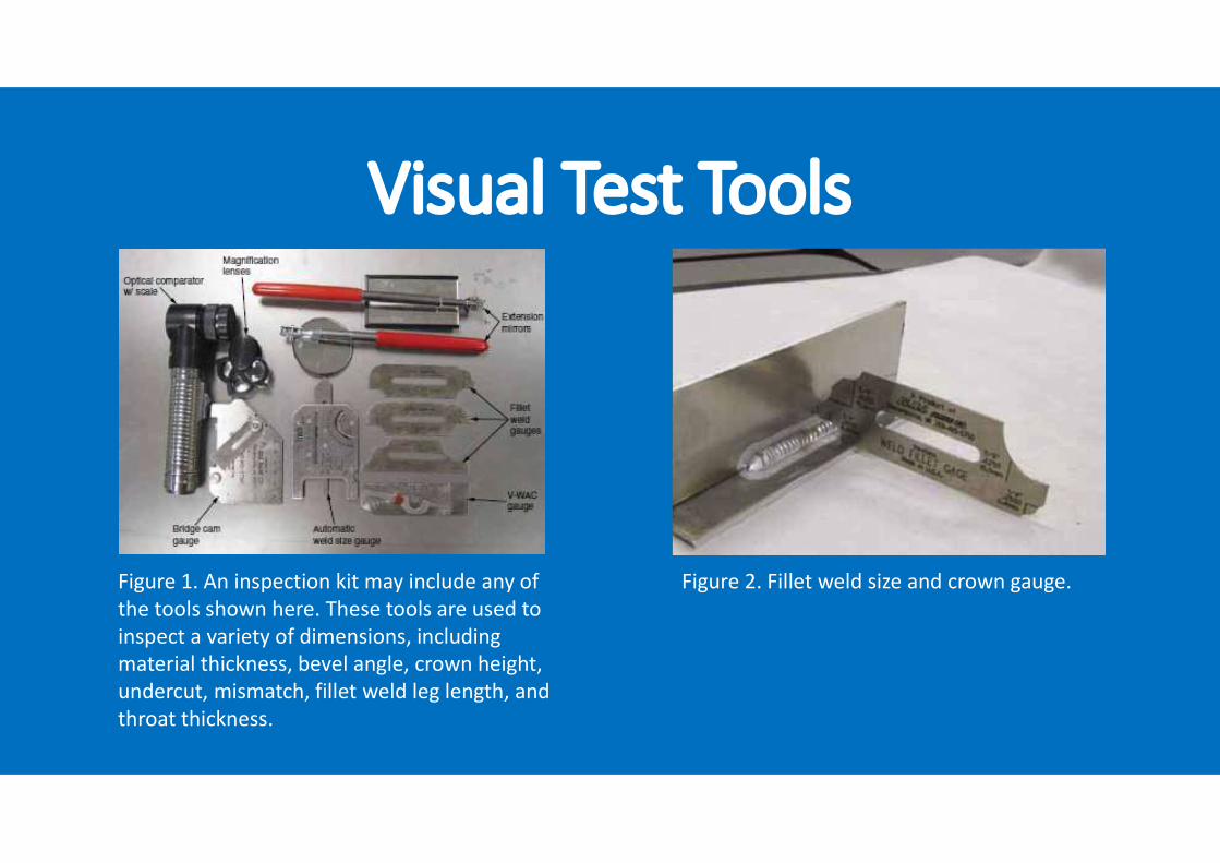
Figure 1. An inspection kit may include any of the tools shown here. These tools are used to inspect a variety of dimensions, including material thickness, bevel angle, crown height, undercut, mismatch, fillet weld leg length, and throat thickness.
Figure 2. Fillet weld size and crown gauge.
Visual Test Tools
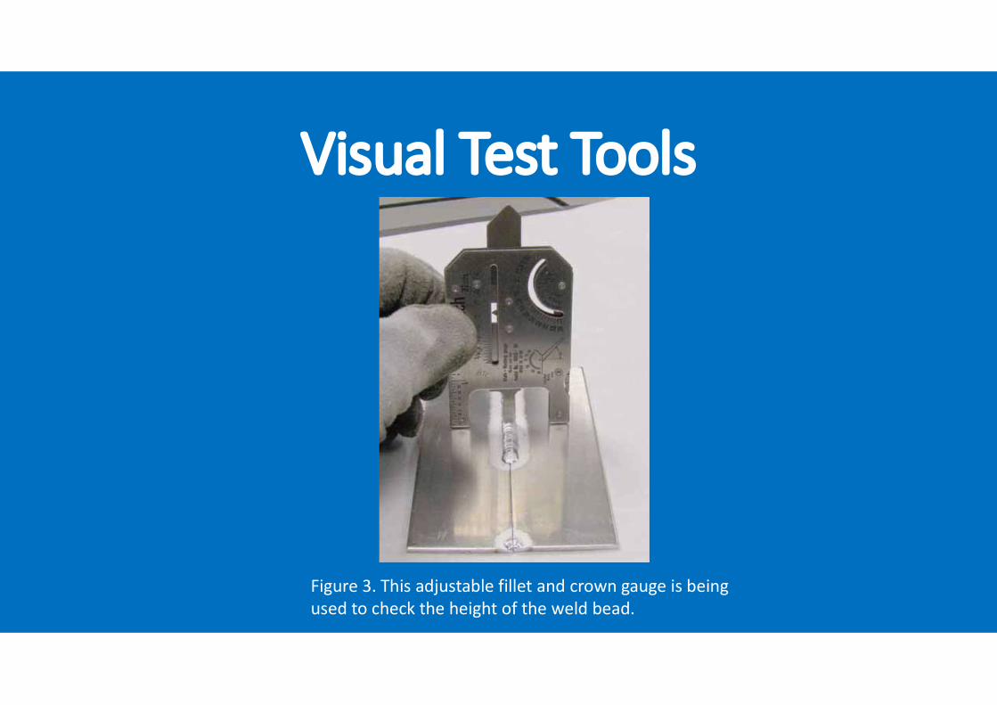
Figure 3. This adjustable fillet and crown gauge is beingused to check the height of the weld bead.
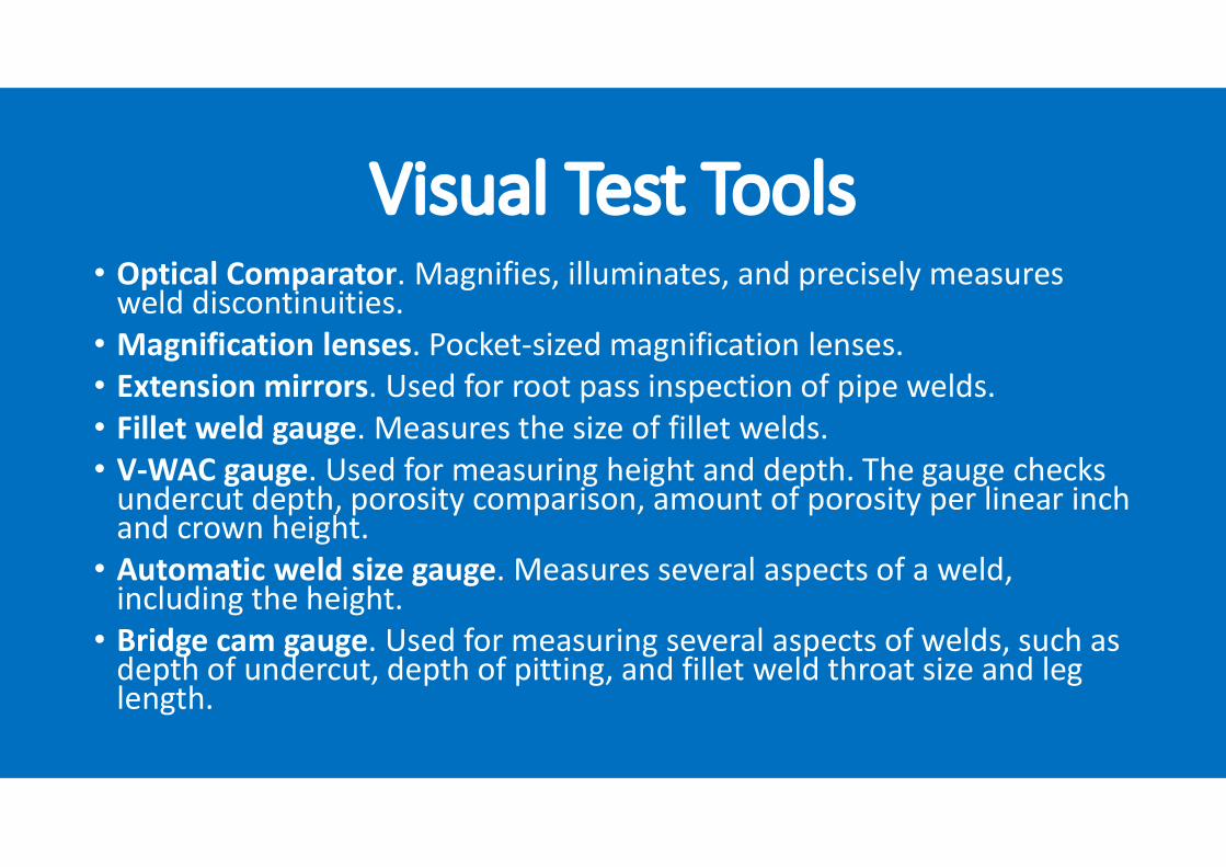
Visual Test Tools• Optical Comparator. Magnifies, illuminates, and precisely measures weld discontinuities.• Magnification lenses. Pocket-sized magnification lenses.• Extension mirrors. Used for root pass inspection of pipe welds.• Fillet weld gauge. Measures the size of fillet welds.• V-WAC gauge. Used for measuring height and depth. The gauge checks undercut depth, porosity comparison, amount of porosity per linear inch and crown height.• Automatic weld size gauge. Measures several aspects of a weld, including the height.• Bridge cam gauge. Used for measuring several aspects of welds, such as depth of undercut, depth of pitting, and fillet weld throat size and leg length.

• Visual tests provide very important information about a weld’s general conformity to specifications.• The following weld features are measured and compared to specifications to ensure that the weld meets expectations:
- crown height- crown profile- weld size- weld length- dimensional variation- root side profile- root side penetration- surface color (titanium welds)
Visual Test (VT)

• In addition, a visual test may reveal discontinuities in the weld. A discontinuity is any disruption in the consistency of a weld. A flaw in the weld is a discontinuity that is small enough that it does not render the weld unacceptable. A defect is a discontinuity that is serious enough to make the weld unacceptable.• The following common problems can be detected by visual tests:
- Undercut- Overlap- Surface cracks- Crater cracks- Surface porosity- Joint mismatch- Warpage
Visual Test (VT)
• A penetrant test (PT) is a sensitive method of detecting and locating minute discontinuities that are open to the surface of the weld.• A penetrating liquid (dye) is applied over the surface of the weld. The fluid then enters the discontinuity. After a short period of time, the excess penetrant is removed from the surface.• A developer is applied to the surface and allowed to dry. The penetrant in the discontinuity rises to the surface by capillary action, making the discontinuity easy to see.• The penetrant test sequence is shown in Figure 4.
2. Penetrant Test (PT)
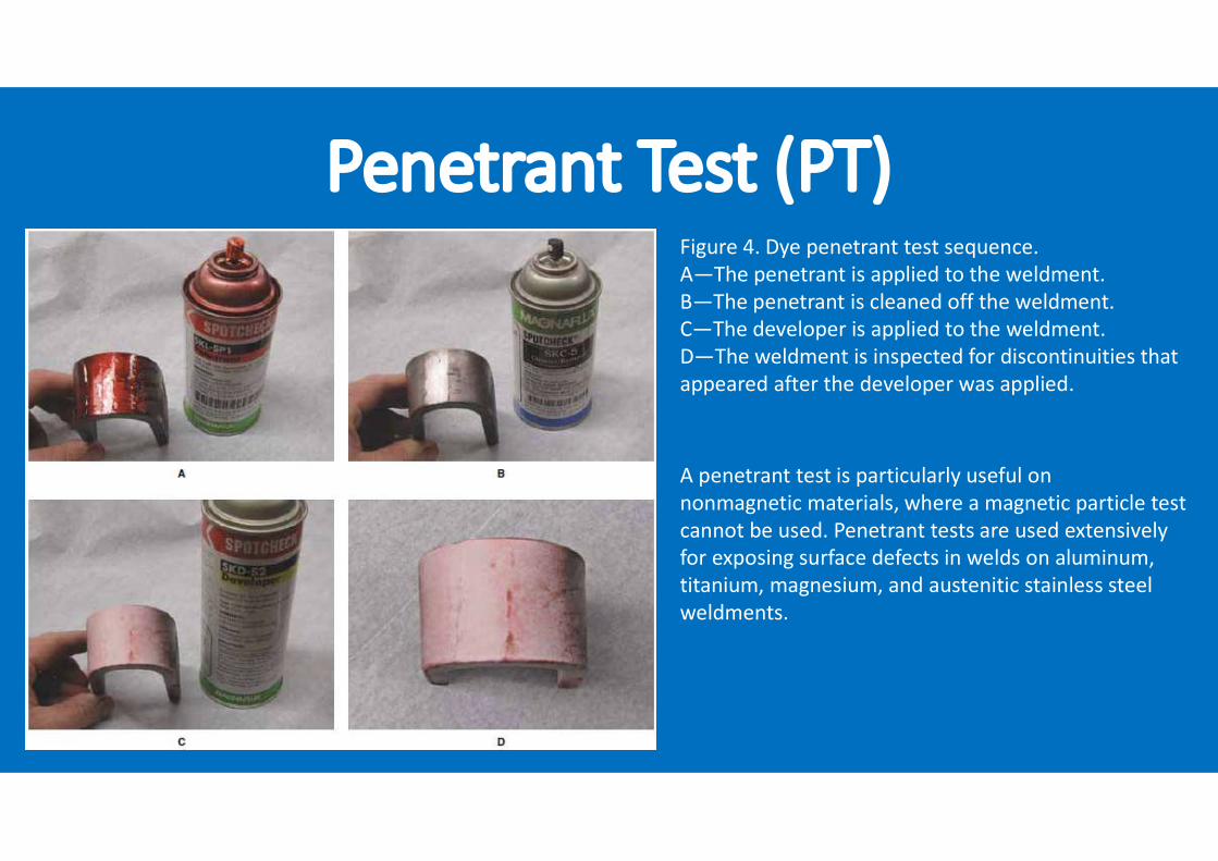
Penetrant Test (PT)Figure 4. Dye penetrant test sequence. A—The penetrant is applied to the weldment. B—The penetrant is cleaned off the weldment. C—The developer is applied to the weldment. D—The weldment is inspected for discontinuities that appeared after the developer was applied.
A penetrant test is particularly useful onnonmagnetic materials, where a magnetic particle testcannot be used. Penetrant tests are used extensivelyfor exposing surface defects in welds on aluminum,titanium, magnesium, and austenitic stainless steelweldments.
Penetrant Test (PT)The two types of penetrant tests are: 1. Dye penetrantA dye penetrant test requires the surface of the weld to be sprayed generously with penetrant and allowed to soak for a specified time. Excessive penetrant is then removed with an aerosol cleaner. All of the penetrant is then wiped from the weld area. After the penetrant is removed, the developer is applied. The developer is a powdery white substance that is lightly applied from an aerosol can. Any imperfections in the weld will hold the dye and bleed through the white developer, identifying the problem. A dye penetrant test can be done anywhere because it is portable, and it can be done in any position. The results can be detected in normal light, without the use of special equipment.
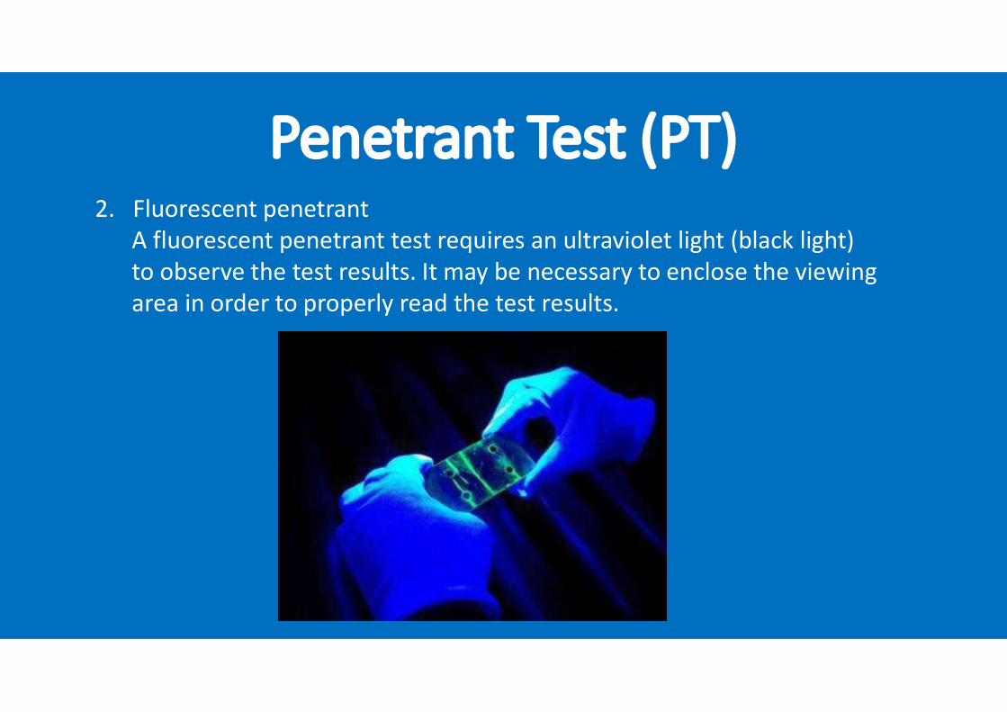
Penetrant Test (PT)2. Fluorescent penetrantA fluorescent penetrant test requires an ultraviolet light (black light) to observe the test results. It may be necessary to enclose the viewing area in order to properly read the test results.
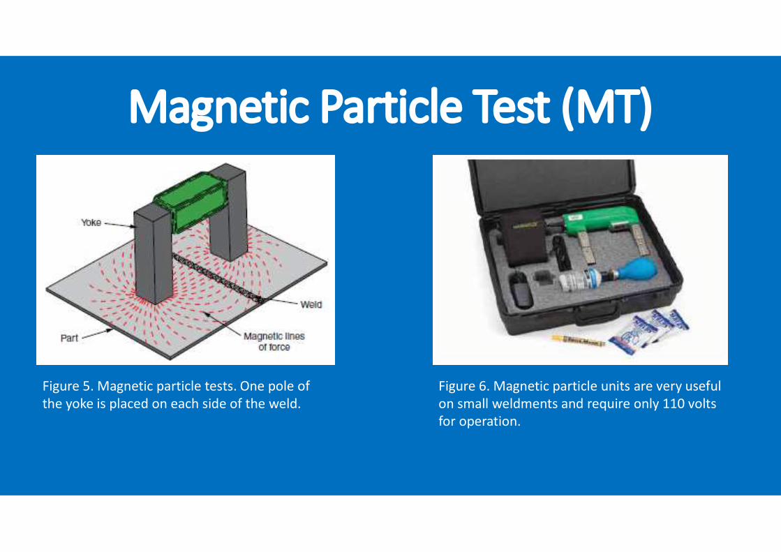
3. Magnetic Particle Test (MT)• A magnetic particle test (MT) is a nondestructive method of detecting cracks, seams, inclusions, segregations, porosity, or lack of fusion in magnetic materials. This test can detect surface defects that are too fine to be seen with the naked eye or that lie slightly below the surface.• When a magnetic field is established in a ferromagnetic material, minute poles are set up at any defects. These poles have a stronger attraction for magnetic particles than the surrounding material has.• In a magnetic particle test, the ferromagnetic material is magnetized by an electric current, and iron particles or powder is applied to the magnetized area. If the magnetic field is interrupted by a defect, the iron particles form a pattern on the surface. The pattern is the approximate size of the defect. Figure 5. shows how magnetic particle tests are performed.• Small, portable, permanent magnets can be used for thin-gauge materials. Heavier material requires power from transformers, generators, or rectifiers. A typical magnetic particle unit is shown in Figure 6.
Magnetic Particle Test (MT)
Figure 5. Magnetic particle tests. One pole of the yoke is placed on each side of the weld. Figure 6. Magnetic particle units are very useful on small weldments and require only 110 volts for operation.
Magnetic Particle Test (MT)• The magnetic particle test can be performed using either the wet or the dry method, depending on the individual application. • The wet method, in which the particles are suspended in a fluid, is generally more sensitive than the dry method. Wet magnetic particle inspection allows for a more even distribution of particles over a large area and is better for detecting very small discontinuities on a smooth surface. • The dry method, which uses finely divided dry particles that are dusted onto a magnetized surface, is better for rough surfaces. • Either red or gray particles can be used in the test. The color selected should provide good contrast with the material being tested.
Magnetic Particle Test (MT)• The test can be modified by adding fluorescent dye to the particles. In this method, an ultraviolet light is used to illuminate fluorescent dye on the iron particles, allowing the inspector to clearly see and interpret the formation of the particles at the defect. As with fluorescent penetrant testing, it may be necessary to examine the weldment in a darkened area.• Accurate interpretation of magnetic particle tests requires training. Discontinuities revealed by the test pattern can be misleading to the untrained eye and may have no consequence on the weld’s acceptability.• If the size of the discontinuity falls within allowable limits, the weld is still acceptable. If the size of the discontinuity is larger than the allowable limit, the weld is rejectable.
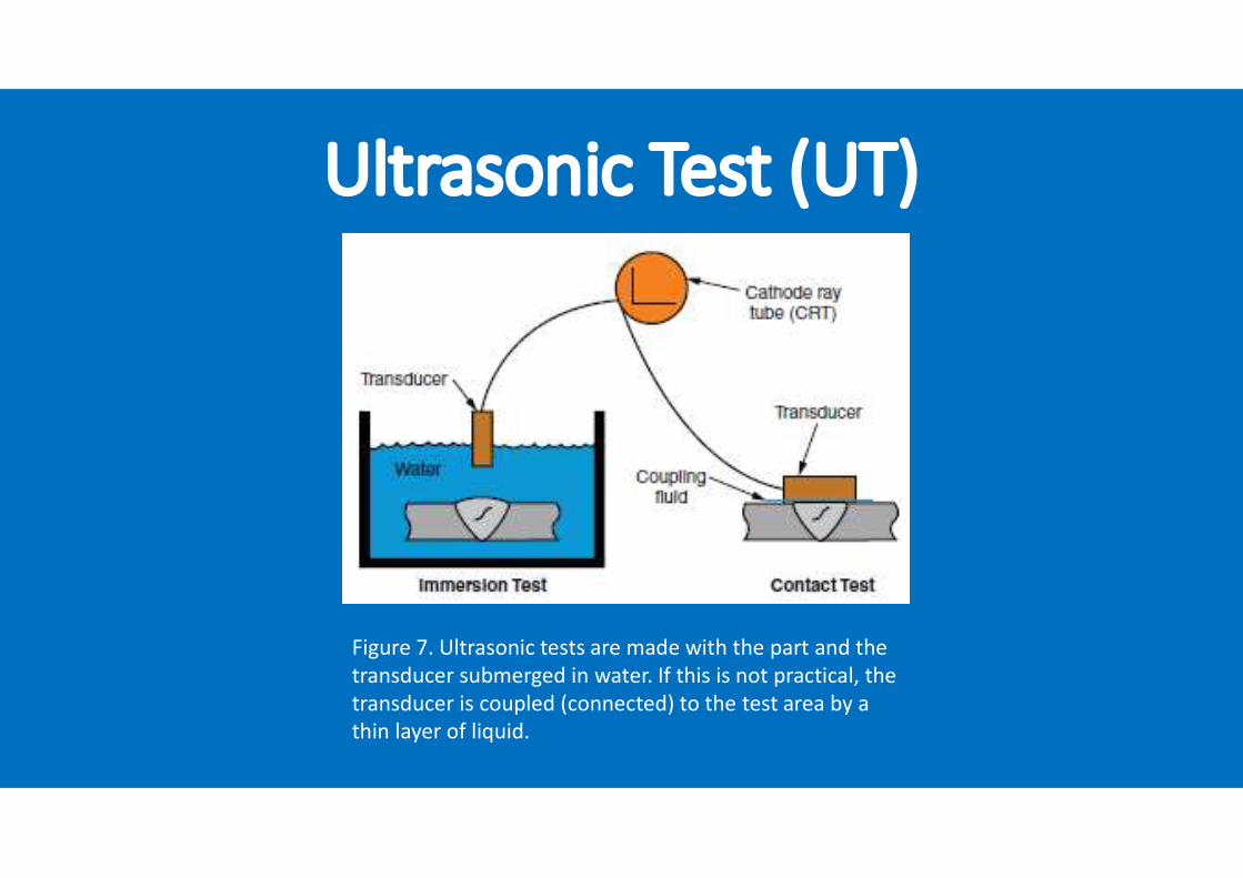
4. Ultrasonic Test (UT)• Ultrasonic testing (UT) is a nondestructive method of detecting the presence of internal cracks, inclusions, segregations, porosity, lack of fusion, and similar discontinuities in all types of metals. It can be used as the sole type of inspection, or it can be used with other types of testing. • UT is often used in conjunction with radiographic testing because it determines the depth of the defect from the test surface.• In ultrasonic testing, very-high-frequency sound waves are transmitted through the part to be tested. The sound waves then return to the sender and are displayed as a graph on a monitoring screen for interpretation.• Since very-high-frequency sound waves travel only short distances in air, the test must be done with the part (signal sender) and the transducer (receiver) immersed in water or with the transducer coupled to the workpiece by a thin liquid film. These two methods are shown in Figure 7.
Ultrasonic Test (UT)
Figure 7. Ultrasonic tests are made with the part and the transducer submerged in water. If this is not practical, the transducer is coupled (connected) to the test area by a thin layer of liquid.
Ultrasonic Test (UT)• UT inspection techniques used depends on the material, weld thickness, welding process, and inspection criteria being used.• Where tests are required out-of-perpendicular with the transducer, a wedge or angle block is placed under the transducer at the desired angle to properly scan the material, as shown in Figure 8.• Ultrasonic testing is portable and nonhazardous. In addition, UT inspection has the following advantages: Great penetration power allows the testing of thick materials. High sensitivity allows detection of small discontinuities in a short period of time. Inspection can be done from one surface.
Ultrasonic Test (UT)• The major disadvantage of ultrasonic testing is the advanced skill required to properly interpret the results. Weld design, location of the defect, internal structure, and complexity of the weldment affect the interpretation of the ultrasonic signal.• In order to achieve the desired results, calibration blocks and reference weld samples are used to calibrate the equipment prior to making the test. With the proper calibration, the operator can then interpret the results to the inspection specification.

Ultrasonic Test (UT)
Figure 8. Wedges or angle blocks are used to sendand receive ultrasonic signals in areas where signaltransmission could be blocked in a straight-line plane.
5. Radiographic Test (RT)• A radiographic test (RT) is a nondestructive method that reveals the presence and nature of discontinuities in the interior of welds.• This test makes use of the ability of short wavelength radiations to penetrate material, such as: 1. X-raysX-rays are a form of electromagnetic radiation that penetrates most materials.An X-ray test is similar to a photograph. A machine in a fixed location transmits X-rays through the material being tested. A film or sensor on the other side of the material is exposed by the X-rays that pass through the test material.Any defects or inconsistencies in the metal change the amount of X-rays that are able to pass through. Because more or fewer X-rays pass through those locations, they look different in the developed film, or display.
Radiographic Test (RT)2. Gamma raysGamma rays are electromagnetic waves that are similar to X-rays, but with a shorter wavelength. Gamma rays are produced from radioactive materials such as cobalt, cesium, iridium, and radium.These radioactive materials must be contained in a lead-shielded box and transported to the job site for in-place radiographs.
Radiographic Test (RT)• The film that is exposed by x rays and gamma rays is called a radiograph. Film is placed on one side of the weld, and the radiation source is placed on the other side of the weld. The radiation passes through the test material and exposes the film, revealing any inconsistencies in the weld. Different types of radiation sources are more or less powerful. The thickness of the material usually determines the type of radiation source used for the test.• A radiograph inspection of a fusion weld is shown in Figure 9. The film is developed for viewing on a special viewer. The radiograph must be compared by a skilled technician to a specification that defines discontinuities. The film must have sharp contrast for proper definition of the weld and identification of any defects. (Contrast is the degree of blackness of the darker areas compared with the degree of lightness of the brighter areas.)
Radiographic Test (RT)
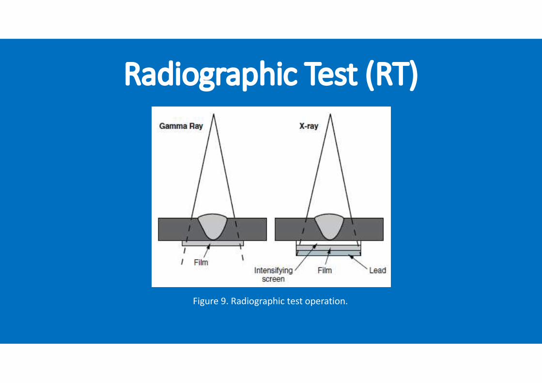
Figure 9. Radiographic test operation.
Radiographic Test (RT)• To ensure sharp images on the film, image quality indicators (IQI), also called penetrameters, are used to indicate the quality of the radiograph.• There are 2 types of penetrameters as follow:1. A hole-type IQI.A hole-type IQI consists of a thin shim of the base metal, usually with a thickness equal to 2% of the weld thickness. One, two, or more holes with various diameters are drilled into the metal shim. The shim is laid next to the weld before being x-rayed. The ability of the radiograph to show definite-sized holes in the penetrameter establishes the radiograph quality. The resolution of the X-ray is indicated by the smallest holethat is visible. Figure 10 shows a hole-type IQI.
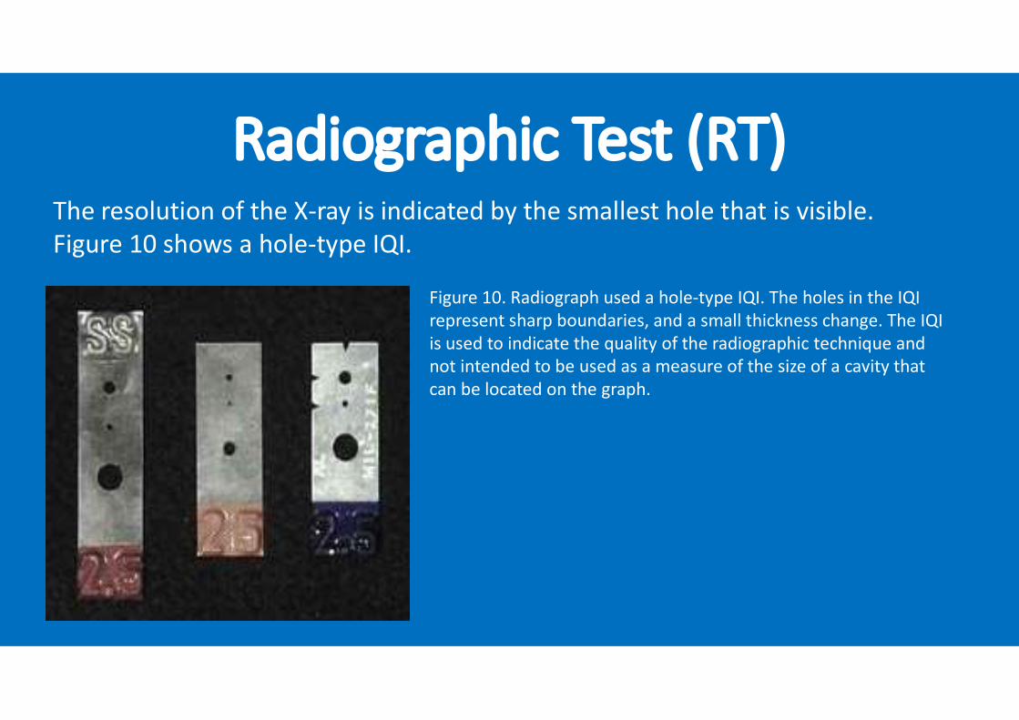
Radiographic Test (RT)The resolution of the X-ray is indicated by the smallest hole that is visible. Figure 10 shows a hole-type IQI.
Figure 10. Radiograph used a hole-type IQI. The holes in the IQI represent sharp boundaries, and a small thickness change. The IQI is used to indicate the quality of the radiographic technique and not intended to be used as a measure of the size of a cavity that can be located on the graph.
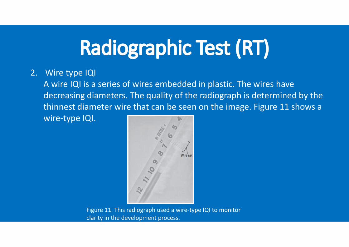
Radiographic Test (RT)2. Wire type IQIA wire IQI is a series of wires embedded in plastic. The wires havedecreasing diameters. The quality of the radiograph is determined by the thinnest diameter wire that can be seen on the image. Figure 11 shows a wire-type IQI.
Figure 11. This radiograph used a wire-type IQI to monitor clarity in the development process.
Radiographic Test (RT)• Radiographs are expensive; however, they provide a permanent record of the weld quality. It is often useful to compare a radiograph created when the weld was first made with later radiographs made after the weldment has been in service. This comparison can help engineers identify areas of the weldment that are stressed by service.


Feel free to contact:Antonius P. Bramono E: [email protected]