welcome to the vehicle communication & measurement … · • this enhanced device combines the...
TRANSCRIPT

1

Welcome to the Vehicle Communication & Measurement Module (VCMM) webinar.
2

In this course we will cover the new features of the VCMM in the following lessons:
• Lesson 1 – Introduction
• Lesson 2 – Tool Power up
• Lesson 3 – Oscilloscope Function
• Lesson 4 – Digital Multimeter (DMM) Function
• Lesson 5 – Signal Generator Function
• Lesson 6 – Vibration Analyzer Function
• Lesson 7 – Driveshaft Balance Function
3

At the conclusion of this course you will be able to:
• identify the features and operation of the VCMM.
4
Welcome to Lesson 1, Introduction.
In this lesson we will cover:
• What is the VCMM
• Features and functions
• Safety instructions
5

• The VCMM is Ford's next generation high performance, rugged, vehicle serial communications and measurement instrumentation gateway.
• This enhanced device combines the functionality of a VCM II, a Vehicle Measurement Module (VMM) and a vibration analyzer into one unit.
• It provides multiple vehicle serial communication interfaces, including other functionality, to meet the requirements for all Ford Motor Company vehicles.
Note: The VCMM is not compatible with Windows XP
6

• The new VCMM can be used just like the VCM II.
• It allows communication between the scan tool and vehicle.
7

The new VCMM replaces the old VMM which is no longer available.
The VCMM has all of the functions of the VMM including:
• A 4-channel oscilloscope
• A Digital Multimeter (DMM) function
• 5th oscilloscope channel routed directly to the Data Link Connector (DLC) pins.
• The new VCMM has time saving features and advantages such as being able to check cam timing without having to remove engine components.
• Another time saver is the fact that you do not have to connect to the DLC using separate probes when using the oscilloscope function.
• Specifically, it is not necessary to use external probes to view HS CAN signals because the 5th channel is connected directly to the VCMM DLC cable.
8

• The new VCMM also provides a signal generator function that can simulate vehicle sensors or other signals on the vehicle.
• It functions similar to the old VMM.
• The new VCMM hardware allows voltage frequencies and waveforms to be displayed with greater resolution.
9

• The new VCMM also provides a vibration analyzer function.
• It can perform all of the same functions as the current Vetronix MTS 4000/4100 vibration analyzer.
10

The following features provide increased durability and ruggedness for the VCMM:
• Protected in a shock resistant polycarbonate case with rubber end boots.
• Extended operating temperature and voltage range.
The VCMM has six LED indicators and a signaling device to provide the user with continuous visual as well as audible operating status.
11

• When power is first applied to the VCMM
• The Vehicle Interface LED (1) will illuminate.
• After 5 seconds the PC Interface LED (2) will illuminate and the Vehicle Interface LED (1) will turn off.
• 10 seconds the Power LED (5) will illuminate and the PC Interface LED (2) will turn off.
• After 15 seconds the speaker will beep for 1 second.
Legend
1. Vehicle Interface LED
2. PC Interface LED
3. Measurement Active LED
4. Error LED
5. Power LED
6. Play / Stop LED
7. Recovery Mode Button
12

• The VCMM has wireless capability when equipped with the USB 2.0 wireless adapter.
• The VCMM still provides detachable cables for direct connection to high-speed USB host interfaces such as laptops, PCs and the vehicle being tested.
13
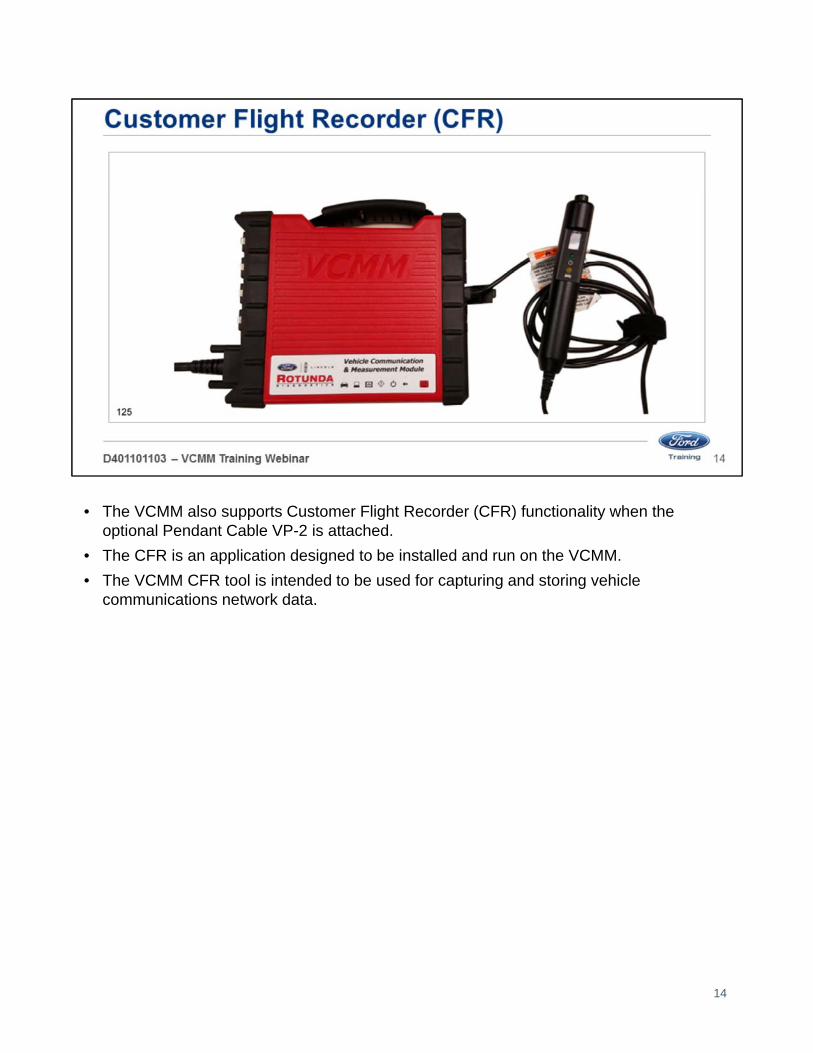
• The VCMM also supports Customer Flight Recorder (CFR) functionality when the optional Pendant Cable VP-2 is attached.
• The CFR is an application designed to be installed and run on the VCMM.
• The VCMM CFR tool is intended to be used for capturing and storing vehicle communications network data.
14

• There are 2 VCMM kits available:
• Standard kit
• Advanced kit
• The contents of the VCMM standard kit are shown here.
• All kits come with the carrying case shown here.
15

• The VCMM standard kit is equipped with these components.
• The standard kit is Item #164-R9822.
16

• An advanced kit is available for the VCMM and includes all the components of the standard kit plus the components listed here.
• The advanced kit is Item #164-R9823.
• There is one other kit that includes the advanced kit as well as a touchscreen laptop (Panasonic® CF-54) it is Item #164-R9824.
• Refer to the Rotunda® tool site for prices and availability.
• Available through Rotunda®
• VMM Current Probe/ PVT adapter to VCMM adapter cable and BNC to VCMM adapter cable
17

WARNING: Failure to follow these instructions will increase the risk of personal injury
1. Read all instructions.2. DO NOT use the VCMM for measurements greater than 60 Volts DC, 30 Volts AC RMS or 42
Volts AC peak. The accessories must only be used in circuits which are not connected to a wall outlet (measuring category 0 according to EN 61010-2-030:2010). The enclosed accessories must only be used with the VCMM and at voltages below the voltage value as imprinted on the accessories. When combining accessories, make sure you do not exceed the lowest voltage value imprinted on the accessories.
3. Care must be taken as burns can occur from touching hot parts or surfaces.4. DO NOT operate the equipment if damage to the unit or cable is suspected.5. DO NOT let cables hang over the edge of the table, bench or counter or come in contact with
hot manifolds or moving fan blades.6. DO NOT place tools or test equipment on vehicle fenders or other places inside the engine
compartment.7. Let equipment cool completely before putting away. Loop cables loosely around equipment
when storing.8. Adequate ventilation should be provided when working on operating internal combustion
engines.9. Keep hair, loose clothing, jewelry, fingers and all parts of the body away from moving parts of
the vehicle.10. Use this equipment only as described in the manual. Use only the manufacturer’s
recommended attachments.11. ALWAYS WEAR SAFETY GLASSES WHEN USING GARAGE EQUIPMENT. Everyday
eyeglasses only have impact resistant lenses, they are NOT safety glasses.
18

Welcome to Lesson 2, Tool Power Up.
In this lesson we will cover:
• Normal power up of the VCMM
• Software updates
• Factory reset
• Wireless connection (initial procedure)
19

There are three different ways to power the VCMM:
• Data Link Connector (DLC)
• 12 volt battery
• AC/DC adapter
20

If making the connection from a PC:
• Connect the type B end of the USB cable included in the VCMM kit to the VCMM high-speed USB client connector.
21

Connect the type A end of the USB cable to the PC USB port.
22

If making the connection from the vehicle:
• Connect the 26-pin end of the Data Link Connector (DLC) cable included in the VCMM kit to the VCMM vehicle interface diagnostic connector and tighten the screws.
23

• Connect the 16-pin end of the DLC cable to the vehicle DLC.
24

If making the connection from the 12 volt battery:
• Connect the positive and negative clamps to the 12 volt battery.
• Insert the DC power plug into the VCMM power port.
25

If making the connection from the AC/DC power supply:
• Connect the AC/DC power supply to a 110V AC power source
• Insert the DC power plug into the VCMM power port.
26

• Just like the VCM II, the user will be prompted to update the VCMM software using a PC when new software releases become available.
• To install an update, open the VCI Manager.
• The VCI Manager is accessed through the desktop icon or through the Start menu –Programs – Bosch – VCI software (Ford).
27
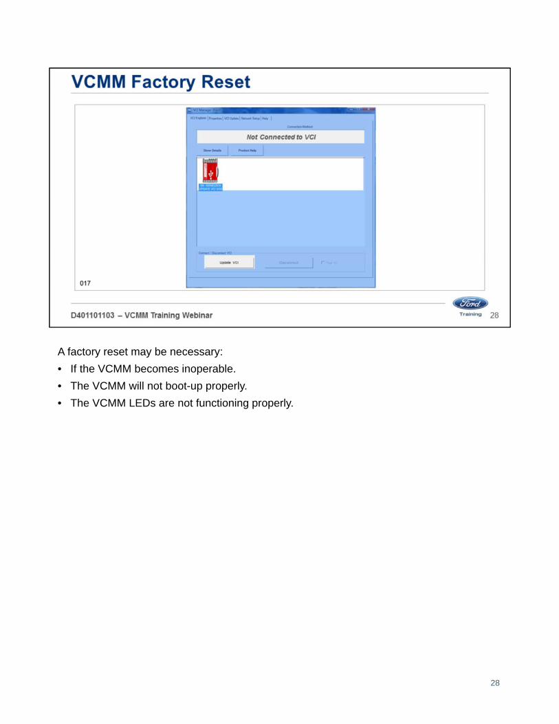
A factory reset may be necessary:
• If the VCMM becomes inoperable.
• The VCMM will not boot-up properly.
• The VCMM LEDs are not functioning properly.
28
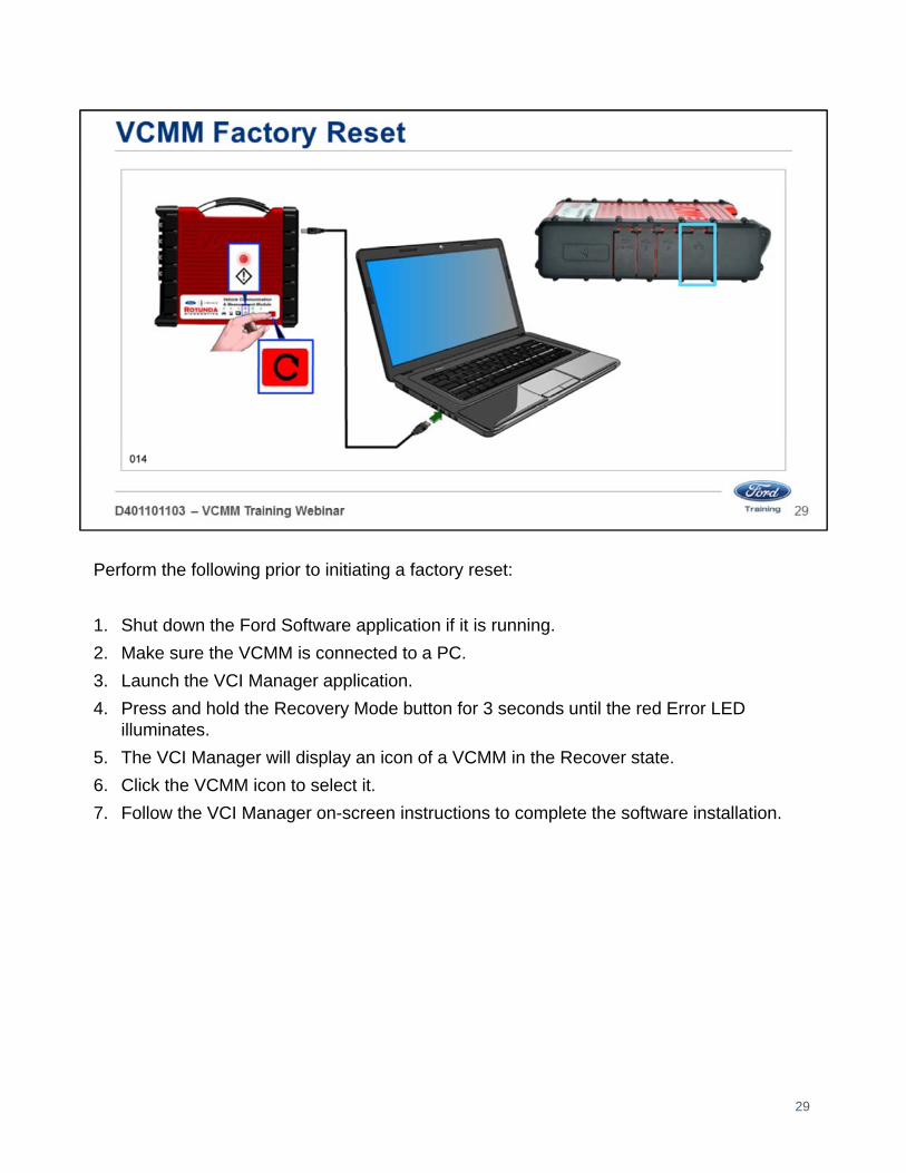
Perform the following prior to initiating a factory reset:
1. Shut down the Ford Software application if it is running.
2. Make sure the VCMM is connected to a PC.
3. Launch the VCI Manager application.
4. Press and hold the Recovery Mode button for 3 seconds until the red Error LED illuminates.
5. The VCI Manager will display an icon of a VCMM in the Recover state.
6. Click the VCMM icon to select it.
7. Follow the VCI Manager on-screen instructions to complete the software installation.
29
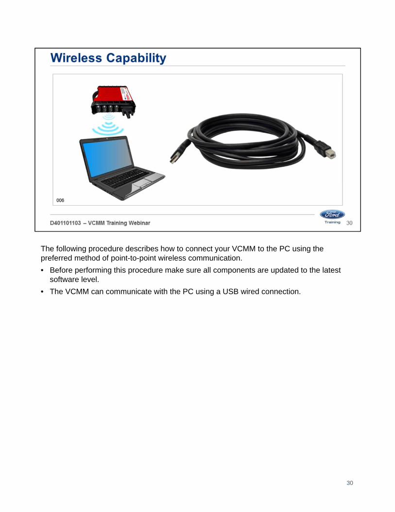
The following procedure describes how to connect your VCMM to the PC using the preferred method of point-to-point wireless communication.
• Before performing this procedure make sure all components are updated to the latest software level.
• The VCMM can communicate with the PC using a USB wired connection.
30

The VCMM ships with two adapters in the kit. These adapters must be installed in the VCMM.
For setting up a VCMM, find one of the two wireless adapters in your kit and install it in your VCMM:
1. Remove the rubber boot from the right side of the unit (looking at the VCMM with the handle up).
2. Insert the wireless adapter into the VCMM as shown below.
3. Put the rubber boot back onto the unit.
31

Install the other wireless adapter from your kit and connect it to a free USB port on your PC.
Note: If you have not installed the wireless adapter before your PC may take some time to install the drivers and software.
32

• The PC may display a popup that indicates it is loading drivers.
• Allow the drivers to finish loading.
• Make sure the adapter is ready to use before proceeding.
33
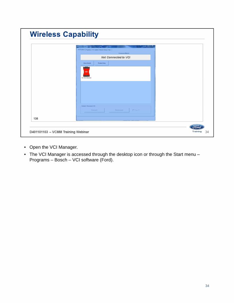
• Open the VCI Manager.
• The VCI Manager is accessed through the desktop icon or through the Start menu –Programs – Bosch – VCI software (Ford).
34

• Connect the VCMM to power using one of the power sources. Do not rely on USB power.
• Connect the type B end of the USB cable to the VCMM high-speed USB client connector.
• Connect the type A end of the USB cable to the PC USB port.
35

Once the connections are made the VCI Manager will show the VCMM in the USB mode.
36

• When you click the Connect button you will see a green check mark appear over the VCMM icon.
• You are now connected to the VCMM through the USB.
• This causes the VCI Manager to transfer some needed wireless information to the VCMM.
• Click on the Disconnect button.
37

• Unplug the type B end of the USB cable from the VCMM high-speed USB client connector.
• VCMM needs to remain powered up.
38

The VCI Manager displays wireless bars on the image of the VCMM to indicate wireless communications are active.
39

• Click on the Connect button to connect the VCMM wirelessly to the PC.
• When the connection is made, the VCI Manager displays a green check mark on the image of the VCMM.
• Close the VCI Manager by clicking on the “X” on the top right corner.
40

Open the Vehicle Measurement System (VMS). The VMS is accessed through the desktop icon or through the Start menu – Programs – Ford Motor Company – Vehicle Measurement System.
Click on any one of the tool icons on the black Vehicle Measurement System launch screen.
• Oscilloscope,
• Digital Multimeter
• Signal Generator
• Vibration Analyzer
41

• In the lower right corner, click on the round red icon.
• Find the serial number of your VCMM unit and click on Connect.
• When it connects, the red round icon will turn green.
• You can now use the Vehicle Measurement System wirelessly.
42

Welcome to Lesson 3, Oscilloscope Function.
In this lesson we will cover the following:
• Oscilloscope screen
• Top Menu
• Oscilloscope
• Channel configuration
• Cursors
• Trigger settings
• Recording
• Screen view
• Other screen settings
43
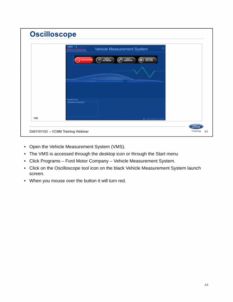
• Open the Vehicle Measurement System (VMS).
• The VMS is accessed through the desktop icon or through the Start menu
• Click Programs – Ford Motor Company – Vehicle Measurement System.
• Click on the Oscilloscope tool icon on the black Vehicle Measurement System launch screen.
• When you mouse over the button it will turn red.
44
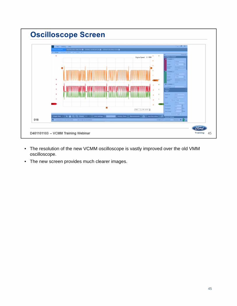
• The resolution of the new VCMM oscilloscope is vastly improved over the old VMM oscilloscope.
• The new screen provides much clearer images.
45

The features of the VCMM oscilloscope set up screen includes:
• The ability to turn the grid lines off.
• Choose the channel signal and grid line thickness.
• Choose grid line colors.
• Choose the background colors.
46

• A full screen button is located in the lower right corner.
• Selecting the full screen button will allow the oscilloscope to fill the screen.
• The configuration menu is hidden in this view.
47

• Under Setting you will see User Preferences
• When User Preferences is selected a popup window will appear to allow languages to be changed
48
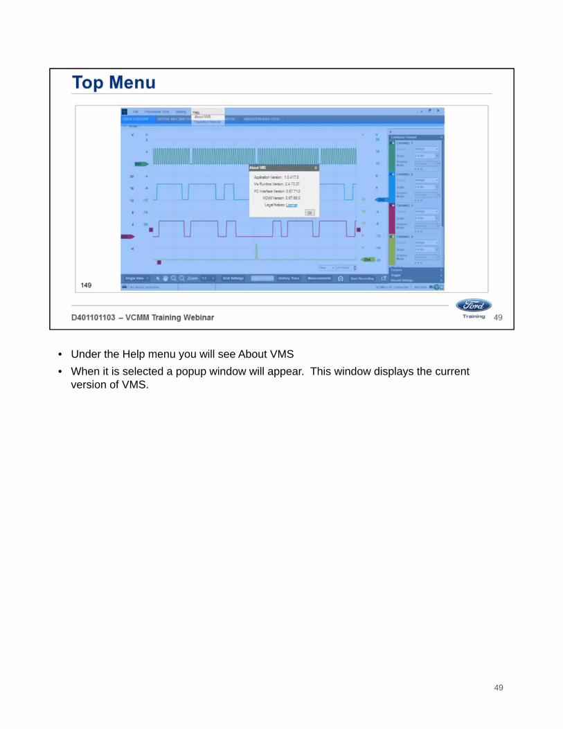
• Under the Help menu you will see About VMS
• When it is selected a popup window will appear. This window displays the current version of VMS.
49

• Under the Help menu you will see Operation manual
• When it is selected a popup window will appear with the current version of the operation manual.
50

• The VCMM has a 4 channel oscilloscope.
• There is also a 5th scope channel routed directly to the Data Link Connector (DLC) pins.
• In this example the red signal is the Crankshaft Position (CKP) sensor 60-2 hall effect.
• Yellow signal is Camshaft Position 1 (CMP1) sensor.
• Green signal is CMP 2.
• This setup is helpful in identifying timing chain stretch or other engine timing related issues.
• In this case the yellow and green signal are almost superimposed on each other.
• This indicates that there is little to or no timing chain stretch.
• If there was an issue the signals would not be as close together.
51

A unique feature of the VCMM is whatever probe color you choose:
• Red, blue, yellow or green
• When you place the probe in one of the channel ports
• That channel changes to the color of the probe.
• This feature helps identify which color probe is placed in which channel port.
For example, if you place the blue probe in the channel 3 port channel 3 turns blue on the screen.
52

Each channel can be turned on or off using the on-screen toggle switch.
53
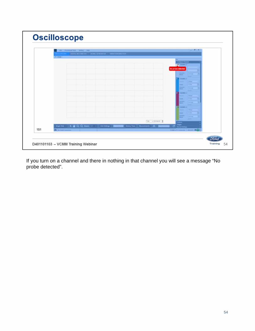
If you turn on a channel and there in nothing in that channel you will see a message “No probe detected”.
54

The test probes of the VCMM are configured as follows:
• The probe has a single wire on the end that is placed into the VCMM.
• The probe end is split into two wires.
• One wire is the color of the probe.
• The other wire is black. This wire should be grounded to the battery negative or chassis ground.
55

• These probes allow you perform differential readings by placing both ends of the probe at different locations of the circuit.
• You can connect ends of the probes to the CAN positive and CAN negative circuits to measure the network using only one probe cable.
For example place the red probe into CAN positive, cavity 6 and the black probe into CAN negative, cavity 14.
• This allows you to measure the differential voltage of the HS 1 CAN with one probe cable.
56

• The probe ends are male banana jacks which allow for several different ends to be placed in the jacks.
• Probes and alligator clips of different sizes are included with the VCMM
57

You will see a screen like this when you place a test probe in one of the channel ports to test for voltage.
• You need to ground the black wire of the probe to battery negative or chassis ground
• If you are performing a differential voltage reading place both ends of the probe at different locations of the circuit.
• You can set the scale from 100 millivolts to 10 volts per division.
58

There are three small dots at the bottom of the channel. When you click them, the menu expands.
• These are defaults and may be changed to suit your testing needs.
In this example channel 2 has been expanded this allows you to select the:
• Coupling
• Filter
• Invert
• Offset
The acquire mode may be selectable or depending on what probe you are using it may be selected for you.
59

This screen appears when you place one of the current probes in one of the channel ports to test for current flow.
• You can set the scale from 1 amp to 10 amps per division.
60

This screen appears when you place the Pressure Vacuum Transducer (PVT) probe in one of the channel ports to test for pressure or vacuum.
• You can set the scale from -15 to 500 PSI.
61

This screen appears when you place the Accelerometer in one of the channel ports.
• You can set the scale from 400 milli Gs (mG/div) to 2 Gs per division (G/div).
62
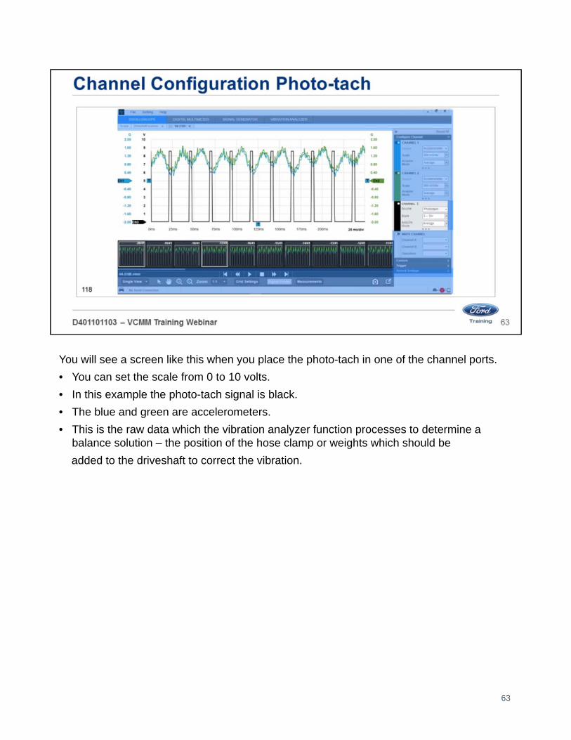
You will see a screen like this when you place the photo-tach in one of the channel ports.
• You can set the scale from 0 to 10 volts.
• In this example the photo-tach signal is black.
• The blue and green are accelerometers.
• This is the raw data which the vibration analyzer function processes to determine a balance solution – the position of the hose clamp or weights which should be
added to the driveshaft to correct the vibration.
63

This screen appears when you place the DLC cable in the DLC port and toggle it on, the DLC port turns orange.
• There are three small dots at the bottom of the channel that, when clicked, expand the menu.
• You are now able to choose the mode and which pins of the DLC to monitor.
• A time per division setting of 100us/div is being used to obtain a view which can be used to assess the overall pattern.
• A time per division setting of 50us/div can be used to identify faults with individual messages.
64

You can choose between three modes:
• Single ended
• Added
• Differential
65
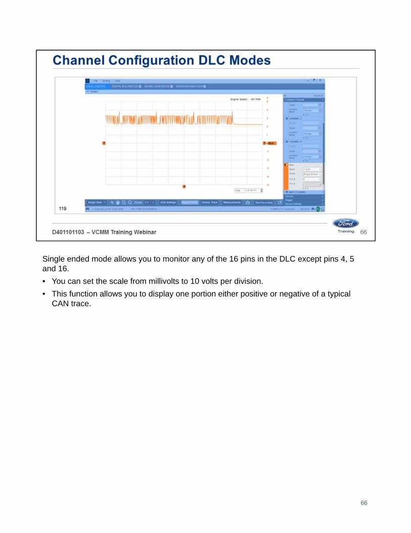
Single ended mode allows you to monitor any of the 16 pins in the DLC except pins 4, 5 and 16.
• You can set the scale from millivolts to 10 volts per division.
• This function allows you to display one portion either positive or negative of a typical CAN trace.
66
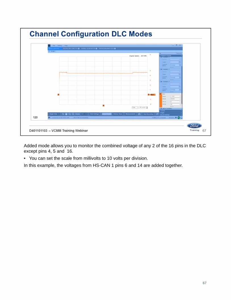
Added mode allows you to monitor the combined voltage of any 2 of the 16 pins in the DLC except pins 4, 5 and 16.
• You can set the scale from millivolts to 10 volts per division.
In this example, the voltages from HS-CAN 1 pins 6 and 14 are added together.
67

Differential mode allows you to monitor the voltage differences between any 2 of the 16 pins in the DLC except pins 4, 5 and 16.
• Differential mode is the subtracted difference between CAN positive and CAN negative.
• If the CAN positive signal peaks at 3.5 volts and the CAN negative peaks in the opposite direction to 1.5 volts the subtractive difference is 2 volts.
For example if you wanted to monitor the voltage differential in the HS-CAN 1
• Select pins 6 and 14.
• Set the scale from millivolts to 10 volts per division.
• The spike at the beginning of each message is the message ID or arbitration.
• The spike at the end of each message is the message acknowledgement.
• This allows you to view the signal in the same manner that a module sees a message.
• Reference the components of a network message in the oscilloscope section of web course 39S01W1 for a description of the function of
message acknowledgement and arbitration.
68

• Expand the Cursors section of the Configuration Pane.
• Two cursors, labeled A and B, can be displayed for each channel.
• Click on a channel’s cursor On/Off button to turn cursors On and Off for the channel.
• A channel’s cursors are displayed as horizontal dashed lines, extending to the channel axis, and drawn in the same color as the channel’s scope traces.
• Vertical cursors are displayed in a similar manner, but are drawn in gray or black, and apply to all channels.
69

You can set the trigger by opening the Trigger section:
1. Select Apply on to whichever channel you want to trigger.
2. Select Type: Auto or Normal.
• Auto mode – If specific trigger conditions are not met in a predetermined amount of time, the VCMM will automatically trigger.
• Normal mode – The scope will only trigger when the set trigger conditions are met.
3. Select the Event to either Rising or Falling:
• Select Rising if you are trying to capture a voltage increase such as a short to voltage.
• Select Falling if you are trying to capture a voltage decrease such as short to ground.
• Please note that the filter was adjusted using the auto setting to filter by the acknowledgement spike.
• This was accomplished by sliding the trigger indicator with a mouse.
4. Pretrigger Settings
• A 50% pretrigger setting was used to allow the start point of the trigger event to occur in the center of the screen.
• The pretrigger can be adjusted so that the start of the trigger event occurs before or after the center of the screen.
70

• You can change recording lengths in the Recording settings.
• You can also take a snapshot by clicking the camera icon at the bottom of the screen.
• Once you have the settings the way you want them.
• Click the start recording button to begin recording.
• Once recorded you can review the recording frame by frame.
71

• You can choose either single or split screen view. In single view you can superimpose the signals over each other.
• Channels 1 and 2 are referenced to ground with an additional differential trace reference (DLC channel).
• A differential trace reference assists in isolating faults to individual messages.
72

In split view you can separate the signals – CAN Hi/CAN Low in a CAN circuit.
73

When you click on the measurements button
• Small window appears at the bottom with digital readouts for each channel in use.
74

The VCMM can still be used to display single trace patterns in the same manner as the prior VMM.
75

The channel trace history feature is accessed using the Control Bar’s History Trace button. This feature retains a history of channel traces, up to a specified maximum.
· Click the On/Off button/slider to enable and disable the history feature.
· When the feature is On, set the maximum number of traces to retain.
76

The Zoom feature allows you to zoom-in on a subset of a scope frame without having to change the data acquisition configuration.
• Zoom is only available in the oscilloscope tool function, and only applies to the time axis there is no vertical axis zoom.
There are three ways to control the zoom:
· Choose the zoom using the zoom combo box.
· Use the zoom icons (+/-) in the Control Bar.
· Resize the viewport within the zoom mini-window.
77

Welcome to Lesson 4, Digital Multimeter (DMM) Function.
• In this lesson we will cover: Digital Multimeter (DMM) function
Measurements:
• Voltage
• Resistance
• Continuity
• Time-based
• Current
• Pressure/Vacuum
• Temperature Settings
78

Open the Vehicle Measurement System (VMS):
• The VMS is accessed through the desktop icon or through the Start menu
• Programs – Ford Motor Company – Vehicle Measurement System.
• Click on the Digital Multimeter tool icon on the black Vehicle Measurement System launch screen.
• When you mouse over the button it will turn red.
79

The DMM function allows up to 4 channels of measurement.
• If you choose more than two channels the readings are displayed in a digital output.
• If you choose less than 2 channels the readings are displayed as a graph.
You can measure:
• DC voltage
• AC voltage
• Resistance
• Continuity
• Direct Current (DC)
• Alternating Current (AC)
• Pressure / Vacuum
• Temperature
• Time based measurements
• Pulse width
• Duty cycle
• Frequency
• Period
80

To measure DC voltage place the test probe in one of the four channels and choose DC Voltage from the drop-down menu:
• Ground the black wire of the probe to the battery negative or chassis ground
• If you are performing a differential voltage reading place both ends of the probe at different locations of the circuit.
• The system defaults to Autorange.
• If you would like to change the scale,
• Click the Scale drop-down menu and select the scale you prefer.
• This function can be used to measure AC voltage as well.
81

To measure resistance place the test probe in one of the four channels:
• Choose resistance from the drop-down menu.
• Place the appropriate leads in the male banana jacks.
• Measure resistance.
• The system defaults to Autorange.
• If you would like to change the scale.
• Click the Scale drop-down menu and select the scale you prefer.
82
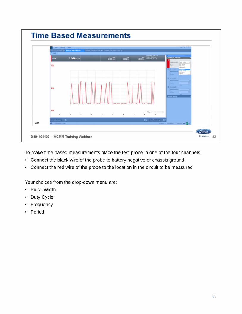
To make time based measurements place the test probe in one of the four channels:
• Connect the black wire of the probe to battery negative or chassis ground.
• Connect the red wire of the probe to the location in the circuit to be measured
Your choices from the drop-down menu are:
• Pulse Width
• Duty Cycle
• Frequency
• Period
83

Place either the 50 amp or 500 amp inductive probe in one of the four channels:
• Choose AC or DC.
• Use the Zero Probe button.
• Choose the scale.
Note: The scale defaults to the probe range.
• Channel 2 in orange is the 0-500 amp probe.
• Channel 3 in black is the 0-50 amp probe.
84

To measure pressure or vacuum place the Pressure Vacuum Transducer (PVT) in one of the four channels:
• Use the Zero Probe button Choose the scale.
• The system defaults to Auto Mode for the scale.
85

You can change recording lengths in Recording settings:
• You can also take a snapshot by clicking the camera icon at the bottom of the screen.
• Once you have the settings the way you want them.
• Click the start recording button to begin recording.
• There is a speaker icon in the lower left side of the screen.
• Click this icon to mute the audible sounds from the tool.
86

Welcome to Lesson, 5, Signal Generator Function.
In this lesson we will cover: signal generator function
87

• The VCMM has all of the signal generator functionality of the VMM.
• The new VCMM hardware has greater resolution for measuring voltage frequencies and waveforms.
• The output is 0-30 volts at 100 milliamps maximum.
88
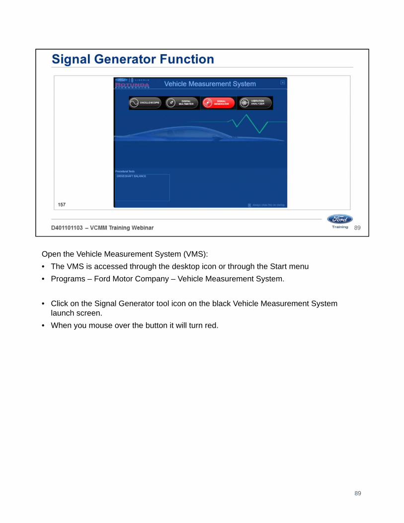
Open the Vehicle Measurement System (VMS):
• The VMS is accessed through the desktop icon or through the Start menu
• Programs – Ford Motor Company – Vehicle Measurement System.
• Click on the Signal Generator tool icon on the black Vehicle Measurement System launch screen.
• When you mouse over the button it will turn red.
89
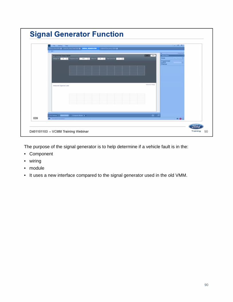
The purpose of the signal generator is to help determine if a vehicle fault is in the:
• Component
• wiring
• module
• It uses a new interface compared to the signal generator used in the old VMM.
90

With the VCMM signal generator function you can generate the following signals:
• Sine wave
• Square wave
• Triangle
• Pulse generator
• DC voltage
• Arbitrary (future function)
91
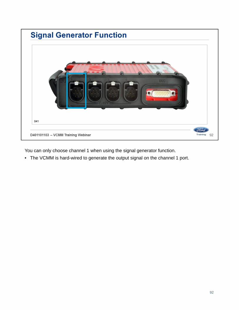
You can only choose channel 1 when using the signal generator function.
• The VCMM is hard-wired to generate the output signal on the channel 1 port.
92

Here is an example of a sine wave signal at 7.5 volts and 10 hertz.
• The top of the screen shows what the signal should look like.
• The bottom of the screen shows the actual signal measured at the load. - Channel 2 is used to obtain this reading.
• This is the display with compare mode off.
93

Here is the same sine wave signal at 7.5 volts and 10 hertz in the compare mode.
• In the compare mode the signals are placed over each other or superimposed.
94

Here is an example of a square wave signal at 7.5 volts and 10 hertz.
95

Here is an example of a pulse generator signal at 7.5 volts and 125 hertz with a duty cycle of 73%.
96

The VCMM signal generator function also has the following features:
• Change the grid settings
• Signal finder
• Compare mode
• Snapshot by using the camera icon at the bottom of the screen.
97
Welcome to Lesson 6, Vibration Analyzer Function.
In this lesson we will cover the vibration analyzer function.
98

The VCMM has all of the vibration analyzer functionality of the Vetronix MTS 4000/4100.
99

Open the Vehicle Measurement System (VMS):
• The VMS is accessed through the desktop icon or through the Start menu
• Programs – Ford Motor Company – Vehicle Measurement System.
• Click on the Vibration Analyzer tool icon on the black Vehicle Measurement System launch screen.
• When you mouse over the button it will turn red.
100

When you open the vibration analyzer a pop-up window appears showing a connection diagram:
1. Connect the VCMM to your scan tool PC.
2. Connect the accelerometer to a free channel on the VCMM.
3. Attach the accelerometer to the seat rail.
Click the Proceed button on the bottom of the page.
101

If you have 2 accelerometers connected, you will see a pop up window like this showing aconnection diagram:
1. Connect the VCMM to your scan tool PC.
2. Connect both accelerometers to a free channels on the VCMM.
3. Drag and drop the A and B icons into the vehicle quadrant (red circles) where the accelerometers are attached to the vehicle.
In this example if you placed accelerometer A on the right front frame.
• Drag the A icon to the red circle on the right front of the frame diagram under step 3.
If you placed accelerometer B on the left rear frame.
• Drag the B icon to the red circle on the left rear of the frame diagram under step 3.
• Click the Proceed button on the bottom of the page.
102

In this screen type in the VIN, year, make and model information.
Note: The Vin is pulled in automatically from the PCM.
103
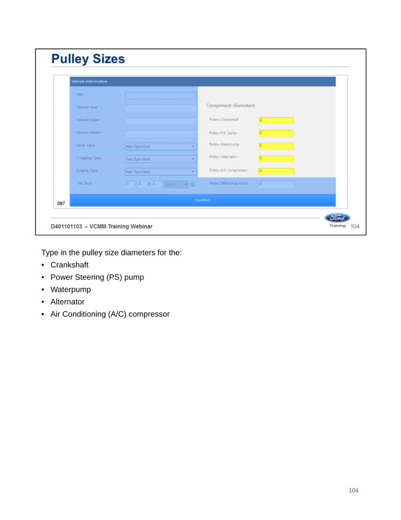
Type in the pulley size diameters for the:
• Crankshaft
• Power Steering (PS) pump
• Waterpump
• Alternator
• Air Conditioning (A/C) compressor
104

Type in the rear differential ratio.
105

Once you record all of the vehicle information you will see the main screen.
• The top half of the screen provides you a chassis diagram based on the type of Drive selected.
• This vehicle is a 4 wheel drive (4WD) truck.
• To the right of the chassis diagram is a list of components.
• accelerometers A and B readings, if you are using both.
In this example items in red indicate an issue.
• On the chassis diagram the drive shafts are red.
• Driveshaft in the components list is red.
• Accelerometer A is red.
This is a first order driveshaft vibration at 87 km/h (54 mph) with an engine speed of 1476 RPMs.
106

The bottom half of the screen provides you with choices on how you would like this data displayed.
• This screen is the frequency spectrum display.
107

You can choose to have the data displayed in a bar graph format.
108

Or you can choose to have the data displayed in a waterfall format.
109
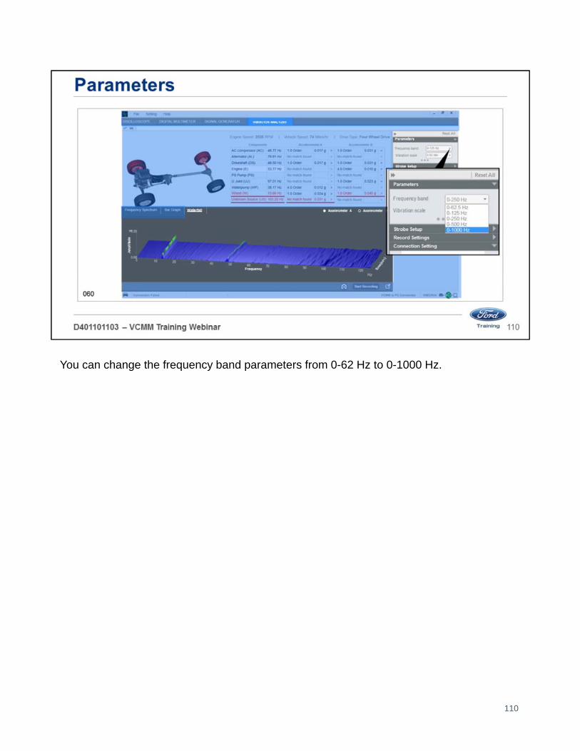
You can change the frequency band parameters from 0-62 Hz to 0-1000 Hz.
110

You can change the vibration scale parameters from 0.002/div to 1.0/div.
111

You can use a strobe light (timing light) to determine if a pulley is out of round or bent.
• The strobe light function triggers the strobe synchronous with a vibration to help isolate the source of the vibration.
• In order to use this feature, you must connect an Induction Loop probe on VCMM channel 1.
112

You can change recording lengths in the Recording settings.
• Once you have the settings the way you want them.
• Click the start recording button to begin recording.
• Take a snapshot click the camera icon at the bottom of the screen.
113

Welcome to Lesson 6, Driveshaft Balance Function.
In this lesson we will cover the driveshaft balance function.
114

Open the Vehicle Measurement System (VMS).
• The VMS is accessed through the desktop icon or through the Start menu
• Programs – Ford Motor Company – Vehicle Measurement System.
• Click on the Driveshaft Balance link located on the left lower section of the black Vehicle Measurement System launch screen.
115

To balance drive shafts you can use the kit shown above.
116
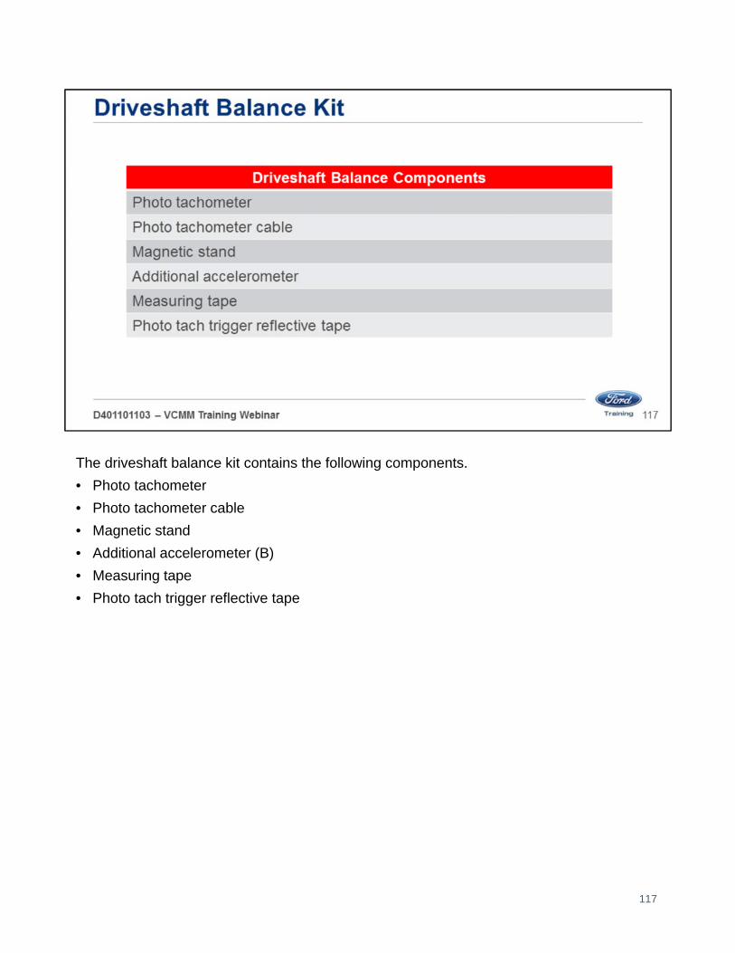
The driveshaft balance kit contains the following components.
• Photo tachometer
• Photo tachometer cable
• Magnetic stand
• Additional accelerometer (B)
• Measuring tape
• Photo tach trigger reflective tape
117

In this screen type in the VIN, year, make and model information.
Note: The Vin is pulled in automatically from the PCM.
118
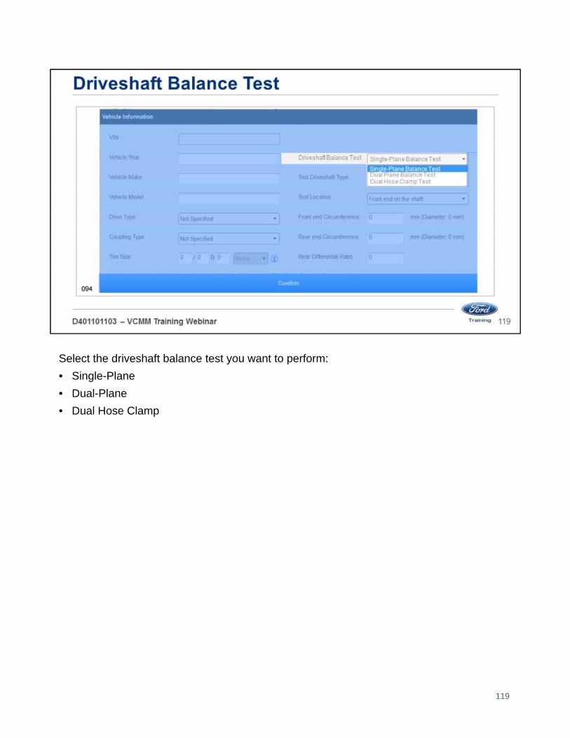
Select the driveshaft balance test you want to perform:
• Single-Plane
• Dual-Plane
• Dual Hose Clamp
119
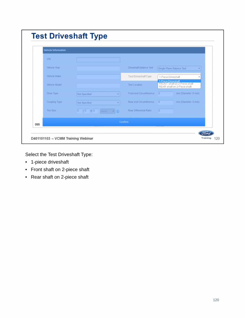
Select the Test Driveshaft Type:
• 1-piece driveshaft
• Front shaft on 2-piece shaft
• Rear shaft on 2-piece shaft
120

Select the Test Location:
• Rear end on the shaft
• Front end on the shaft
• Both ends on the shaft
121

Measure the front end circumference in millimeters using the supplied measuring tape.
122

Measure the rear end circumference in millimeters using the supplied measuring tape.
123

Type in the rear differential ratio.
124

Once you record all of the vehicle information you will see the preparation screen.
• Follow the on-screen instructions.
125

1. Prevent the vehicle from rolling. With the engine OFF place the vehicle in N (Neutral) and release the parking brake.
2. Securely raise the vehicle off the ground so the drive wheels spin freely. On some vehicles, it is necessary to disable the Traction and/or Stability control system.
3. Gain access to the length of driveshaft to be balanced.
4. Determine the direction the driveshaft turns to move the vehicle forward. Use a marker to draw an arrow on the driveshaft to note direction of rotation.
5. Check for and remove debris wedged between tire treads on drive wheels.
126
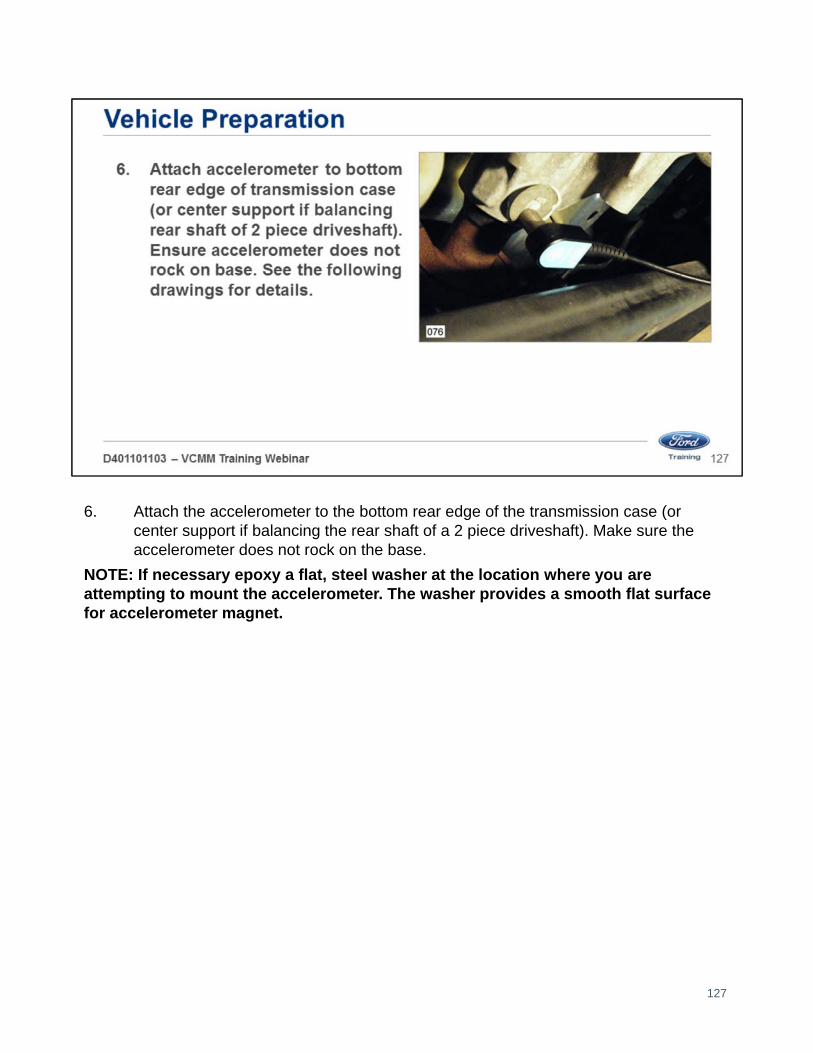
6. Attach the accelerometer to the bottom rear edge of the transmission case (or center support if balancing the rear shaft of a 2 piece driveshaft). Make sure the accelerometer does not rock on the base.
NOTE: If necessary epoxy a flat, steel washer at the location where you are attempting to mount the accelerometer. The washer provides a smooth flat surface for accelerometer magnet.
127

7. Connect the accelerometer cable to one of the channel inputs on the VCMM.
8. Attach a 1/2" x 1" strip of reflective tape, long edge lengthwise along the length of driveshaft where Photo-Tach beam will be unobstructed.
128

9. Connect the Photo-Tach cable to the Photo-Tach connector on Analyzer.
Note: Do not align the beam perpendicular to the driveshaft. A slight angle is recommended to help prevent shine reflection from the aluminum driveshaft.
129

10. Position the Photo-Tach in a location where the beam illuminates the reflective tape. The distance between the Photo-Tach and the driveshaft should be between 6" and 18" (152 to 457 mm).
130
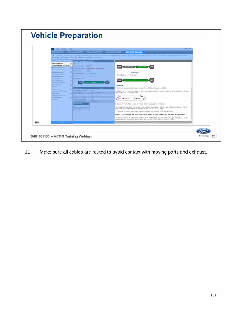
11. Make sure all cables are routed to avoid contact with moving parts and exhaust.
131
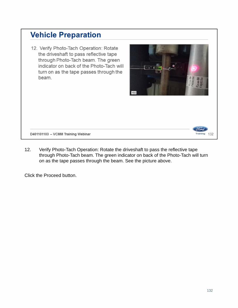
12. Verify Photo-Tach Operation: Rotate the driveshaft to pass the reflective tape through Photo-Tach beam. The green indicator on back of the Photo-Tach will turn on as the tape passes through the beam. See the picture above.
Click the Proceed button.
132

Once you click the proceed button, you will see the base measurement screen. Follow the on-screen instructions.
This screen has you:
1. Start the vehicle.
2. Shift the transmission to a higher gear that allows good control of driveshaft speed.
3. Enter the driveshaft test speed. In this case we entered 2500 RPMs.
133

Press the accelerator and maintain the driveshaft RPM in the green target area.
134

Continue to do this until this message appears.
135

• Enter the test weight.
• We have entered 14 grams which is the approximate weight of a typical hose clamp.
• Identify the center line of the driveshaft.
• Install the center of the hose clamp mass on the center line.
136

Press the accelerator and maintain the driveshaft RPM in the green target area.
137

Continue to do this until this message appears.
138

The results are displayed here.
• In this case there is an imbalance of approximately 71 grams.
139

This screen informs you where to place the location of the balance weight.
• In this case you would place the hose clamp 74 mm from the test weight in the direction of the driveshaft rotation.
• Then you would remove your test weight from the driveshaft and retest.
140
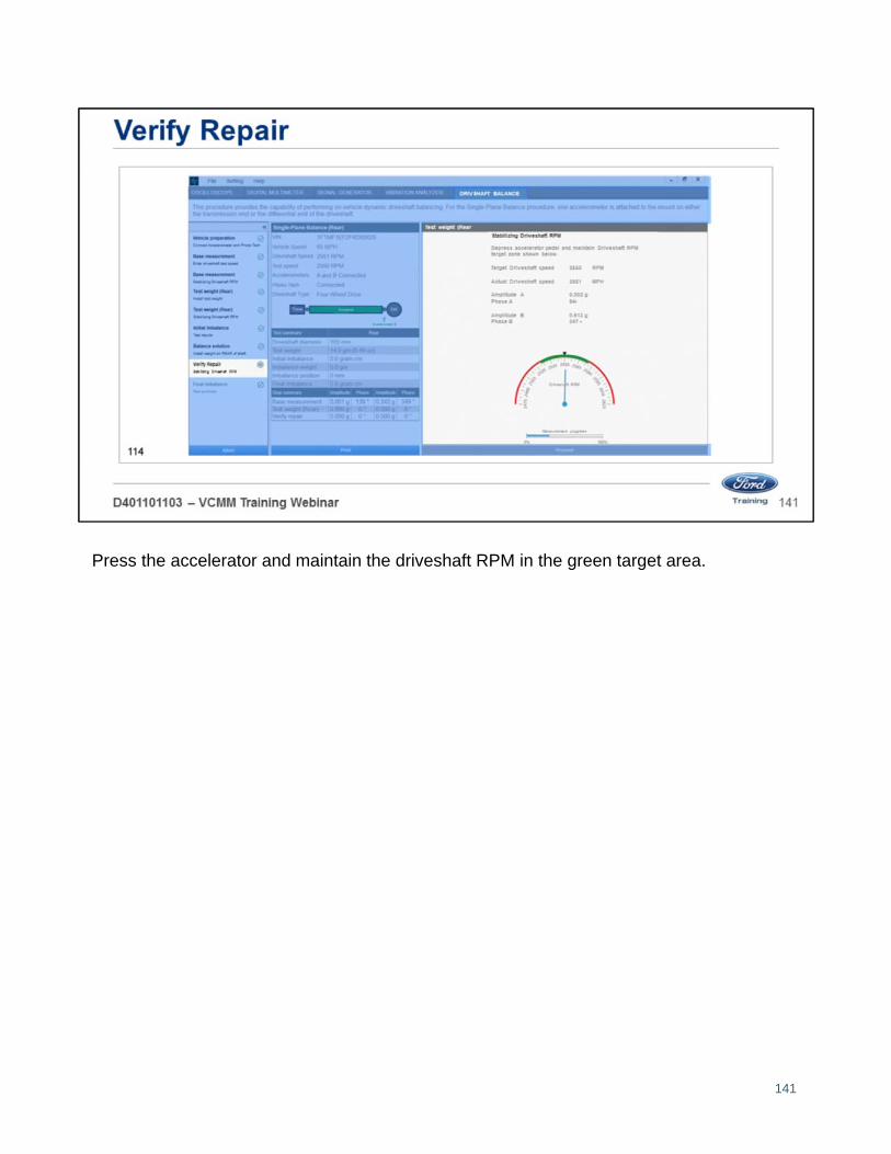
Press the accelerator and maintain the driveshaft RPM in the green target area.
141

This screen informs you of the final results.
• In this case the initial imbalance was approximately 61 grams.
• After performing the procedure the result is approximately 40 grams.
• An improvement of 33%.
142

Instructor
• Select “Sync” button at lower right to allow students to navigate PowerPoint from their screen
143

144

145

146