welcome to the third edition of tyco safety product’s fire...
TRANSCRIPT


Page 1
Welcome to the Third Edition of Tyco Safety Product’s Fire Product Catalogue of product available from our Letchworth UKDistribution Centre. We aim to make your product range as comprehensive as possible to ensure you never need go anywhereelse. To meet this goal, our product specialists, with your help, have selected the most appropriate, cost effective product range allavailable for next day delivery.
In line with our ISO 9000 accreditation, only those products that meet the highest quality criteria have been included.
Our warehouse is one of the largest Fire & Security product distribution centres inEurope. Our goal is to despatch product on the same day as we receive yourorder. Our warranty and service returns policy is second to none. We recognisethat your business is highly dependant on excellence in customer service and tohelp achieve this we offer extended warranty from many of our suppliers. Full creditis also available on a “No Question – No Fuss” basis for any new in-warrantyproduct returned to the distribution centre.
Our training department offers comprehensive sales, design and engineering training onour complete range of products. We recommend you take advantage of this free ofcharge service. As always, training can be undertaken any time, anywhere to suit yourbusiness needs. Contact our telephone Help Line for further information.
Tyco Safety Product’s Web site contains an endless supply of productrelated information. It is regularly updated and features many aids to theselling process including presentation material, independent product testresults and detailed technical information.
Our web site can be found at www.tycosafetyproducts-europe.com
To enhance customer specifications and quotations we also provide a series of productdatasheets which can give our clients an opportunity to read more about the product.We are positive that together we can help grow your business and we look forward toworking with you in the future.
For further details on this catalogue, contact our customer telephone Help Line on +44 1932 74 3327.
Introduction

Page 2
Table of Contents
3 Addressable Fire Systems - LPCB Approved15 Addressable Fire Systems - UL/FM Approved23 Conventional Fire Alarm Panels - BS5839 & EN5436 Conventional Marine Panels39 Batteries, PSU & Door Release Units41 Addressable 900 Series Detectors44 Conventional 600 Series Detectors48 Standard Detector Bases49 Functional Detector Bases53 M600/900 Detector Ancillaries54 Duct Probe Air Sampling55 Aspirating Smoke
Detectors VESDA - Visions Systems
59 Special Hazard Detectors
62 Intrinsically Safe Point Detectors
67 Intrinsically Safe Barriers & Housings
69 Beam & Linear Heat Detectors
72 Detector Test Equipment
74 CP Series Callpoints80 Fulleon Range of Sounders84 MINERVA Range of Sounders87 MINERVA Firecryer - Voice
Enhanced Sounders88 Visual Indicators90 Auxiliary Interface Relays/Miscellaneous Fire
Equipment92 Water Leak Detection Alarms93 Wire Free Product Range98 Approvals Listing of Company Equipment
Page 3
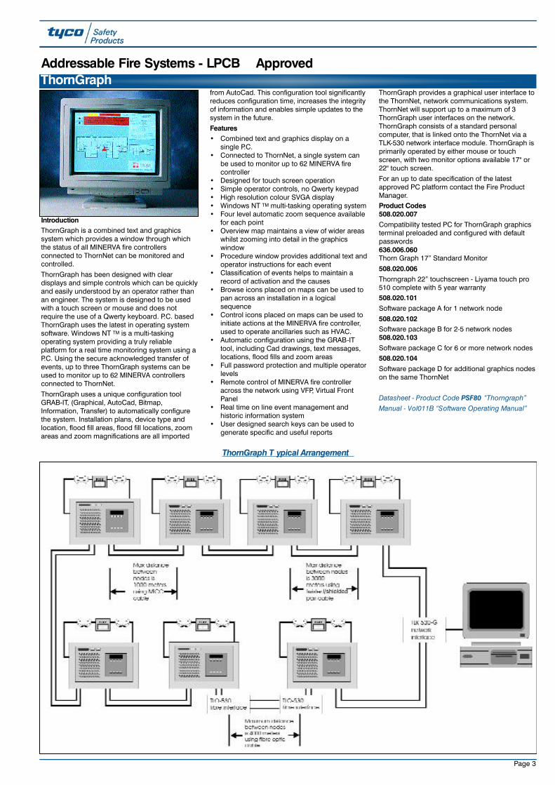
IntroductionThornGraph is a combined text and graphicssystem which provides a window through whichthe status of all MINERVA fire controllersconnected to ThornNet can be monitored andcontrolled.
ThornGraph has been designed with cleardisplays and simple controls which can be quicklyand easily understood by an operator rather thanan engineer. The system is designed to be usedwith a touch screen or mouse and does notrequire the use of a Qwerty keyboard. P.C. basedThornGraph uses the latest in operating systemsoftware. Windows NT TM is a multi-taskingoperating system providing a truly reliableplatform for a real time monitoring system using aP.C. Using the secure acknowledged transfer ofevents, up to three ThornGraph systems can beused to monitor up to 62 MINERVA controllersconnected to ThornNet.
ThornGraph uses a unique configuration toolGRAB-IT, (Graphical, AutoCad, Bitmap,Information, Transfer) to automatically configurethe system. Installation plans, device type andlocation, flood fill areas, flood fill locations, zoomareas and zoom magnifications are all imported
from AutoCad. This configuration tool significantlyreduces configuration time, increases the integrityof information and enables simple updates to thesystem in the future.
Features• Combined text and graphics display on a
single P.C.• Connected to ThornNet, a single system can
be used to monitor up to 62 MINERVA firecontroller
• Designed for touch screen operation• Simple operator controls, no Qwerty keypad• High resolution colour SVGA display• Windows NT TM multi-tasking operating system• Four level automatic zoom sequence available
for each point• Overview map maintains a view of wider areas
whilst zooming into detail in the graphicswindow
• Procedure window provides additional text andoperator instructions for each event
• Classification of events helps to maintain arecord of activation and the causes
• Browse icons placed on maps can be used topan across an installation in a logicalsequence
• Control icons placed on maps can be used toinitiate actions at the MINERVA fire controller,used to operate ancillaries such as HVAC.
• Automatic configuration using the GRAB-ITtool, including Cad drawings, text messages,locations, flood fills and zoom areas
• Full password protection and multiple operatorlevels
• Remote control of MINERVA fire controlleracross the network using VFP, Virtual FrontPanel
• Real time on line event management andhistoric information system
• User designed search keys can be used togenerate specific and useful reports
ThornGraph provides a graphical user interface tothe ThornNet, network communications system.ThornNet will support up to a maximum of 3ThornGraph user interfaces on the network.ThornGraph consists of a standard personalcomputer, that is linked onto the ThornNet via aTLK-530 network interface module. ThornGraph isprimarily operated by either mouse or touchscreen, with two monitor options available 17" or22" touch screen.
For an up to date specification of the latestapproved PC platform contact the Fire ProductManager.Product Codes508.020.007Compatibility tested PC for ThornGraph graphicsterminal preloaded and configured with defaultpasswords636.006.060Thorn Graph 17” Standard Monitor
508.020.006Thorngraph 22” touchscreen - Liyama touch pro510 complete with 5 year warranty508.020.101Software package A for 1 network node
508.020.102Software package B for 2-5 network nodes508.020.103Software package C for 6 or more network nodes 508.020.104Software package D for additional graphics nodeson the same ThornNet
Datasheet - Product Code PSF80 “Thorngraph”Manual - Vol011B “Software Operating Manual”
ThornGraph
ThornGraph T ypical Arrangement
Addressable Fire Systems - LPCB Approved

Page 4
The Telephone Line Drive Module (TLD-530) isused to interface two (2) dedicated telephone linecircuits to the TLK-530 module. The TLD-530 linedriver module converts the RS-485 signalsreceived from the TLK-530 network interfacemodule to signals capable of being transmittedover the telephone line circuits.One TLK-530supports two channels so only one module isrequired per controller for both single path andredundant path star connections. The interfaceallows for field configured baud rates andsupports distances of up 3,000 meters. Up to twounits can be fitted into a TLO/TLD Housing
Technical SpecificationDimensions: 170H x 120W x 20D mm
Product Codes557.180.699TLD 530 ThornNet direct line driver PCB
557.180.148.ATLO/TLD Housing - ADTbranded
ThornNet provides a true peer to peercommunications interface for up to 62, MINERVA8, MINERVA 16E or MINERVA 80 fire controllers inany combination and the ThornGraph, graphicaluser interface. The units can be inter-connectedinto a large network without the need for a host ormaster controller. ThornNet is based upon acombination of hardware and software that allowsMINERVA fire controllers (Nodes) to be linkedtogether. The ThornNet supports up to 61,380analogue/addressable points, 4,960 zones andover 7,000 digital I/0 points. The network co-ordinates and distributes alarm annunciation andsupervises system operation. When connected tothe network, each MINERVA controller maintainsits full stand-alone features, functions andcapabilities.Features• LPCB approved• A peer to peer network that does not use a
host or master controller.• 62 nodes, 61,380 points, 4,960 zone capacity.• Virtual Front Panel (VFP) enables an operator
to interrogate and control any MINERVAcontroller from the keypad/display of any otherMINERVA controller.
• Bi-directional signalling.• Open/short circuit isolation.• Open/short circuit location.• Events originating at any MINERVA controller
can be used as an input to event/action
processing of other panels to co-ordinate anddistribute systems control.
• System can be configured in the field usingConsys software.
• Failure of one node does not affect any othernode or communications between nodes. Inthe event of multiple failures, nodes willautomatically re-generate into independentfully functional networks.
• Automatic network re-configuration when apreviously failed node is restored to thenetwork.
• Up to 3,000 meters between nodes withtwisted/shielded cable.
• System will operate on standard 2 core MICC.• MINERVA controllers may be grouped into
sub-nets where each panel is programmed tointer-act only with other selected controllers.
• Plug-in module (TLK-530) easily connects aMINERVA fire controller to the network.
• Data is re-generated at each MINERVAcontroller and is sent out over the ThornNet asnew clean data. All degradation in receiveddata due to noise on a line, line attenuation, orphase shifting is eliminated when the data isre-generated.
• The ThornNet uses a token-passing, noncollision communication protocol for datatransmission.
• "Network zones" and "sectors" allow thenetwork controllers to be configured as a
single "seamless" system.• ThornGraph, a P.C. based graphical user
interface, connects directly on to the network.• ThornNet supports combinations of MICC,
twisted/shielded pair cabling, fibre opticcabling, and dedicated telephone line.
• Multiple communication topologies bus orring.
The MINERVA ThornNet communications networkis a collection of network interface modules andperipheral equipment that together form anetwork.Product Codes557.180.219ThornGraph PC to TLK-530-G connection cable 557.180.148.ATLO/TLD housing for a combination of 2 xTLO530 or TLD530 Communication interfaces(ADT branded)557.180.147Spare TLK -530 firmware Version 2.36
Datasheet - Product Code PSF81 “ThornNet”Manual - Vol07A-04-D1 “Communications SystemsManual”
557.180.218TLK 530G ThornNet interface for ThornGraph PCc/w 240V PSU and housing
ThornNet
The Fibre Optics Module (TLO-530) is used tointerface one fibre optic channel to the TLK-530module. The TLO - 530 fibre optic interfacemodule converts RS-485 digital data currentpulses from the TLK-530 network interfacemodule to light pulses. The light pulses are thencarried over fibre optic cabling to another TLO-530 where the pulses are converted back to RS-485 digital data current pulses. Two TLK-530modules are required per panel for redundantpath star connections and when using fibre opticsin both directions of ring and bus connections.Two (2) type 62.5/125 fibres between controllers(4 fibres when using redundant path starconnections) allow the interface to transmit
signals at 38.4 Kbs at distances as high as 4,000meters between controllers. Up to two units can be fitted into a TLO/TLDHousing which has a chassis plate toaccommodate the units.Technical SpecificationDimensions: 210H x 130W x 30D mmProduct Codes 976166TLO 530 ThornNet fibre optics interface assembly557.180.148.ATLO/TLD Housing - ADT branded
The key hardware component that makes thenetwork possible is the TLK-530 module. The TLK-530 provides the electrical/mechanical means toconnect the components of the network to localand remote network signalling circuits. Installationof the TLK-530 is simplified with an edgeconnector that plugs onto the main processorboard of the MINERVA controller. The TLK-530provides RS-485 communications over a twistedshielded pair as a standard configuration. Thedistance between controllers can reach 3,000meters at a speed of 38.4 Kbs using 18AWGtwisted shielded cable.
Fits within the MINERVA housing.
TLK-530
557.180.215TLK530 ThornNet network node interface module
(Note: Functionally the same as TFX-TLI530)
TLO-530
TLD-530
Page 5
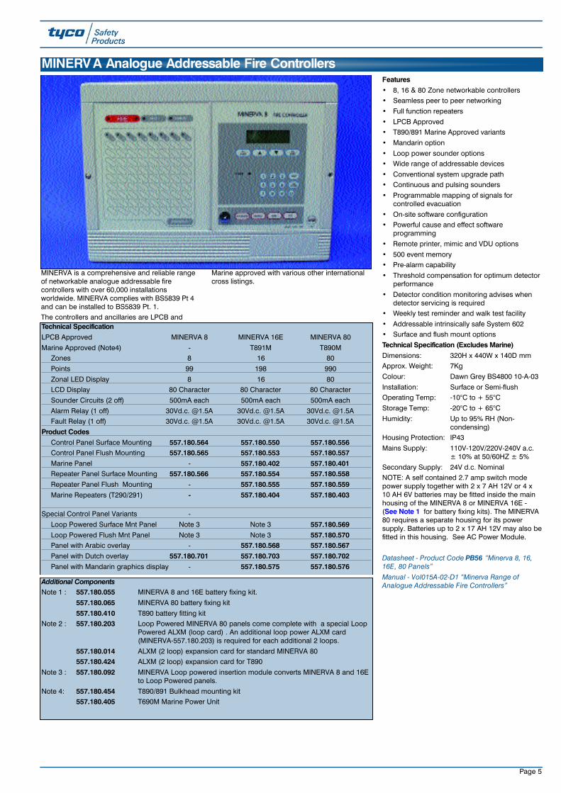
MINERVA is a comprehensive and reliable rangeof networkable analogue addressable firecontrollers with over 60,000 installationsworldwide. MINERVA complies with BS5839 Pt 4and can be installed to BS5839 Pt. 1. The controllers and ancillaries are LPCB and
Marine approved with various other internationalcross listings.
Features• 8, 16 & 80 Zone networkable controllers• Seamless peer to peer networking
• Full function repeaters
• LPCB Approved• T890/891 Marine Approved variants
• Mandarin option
• Loop power sounder options• Wide range of addressable devices
• Conventional system upgrade path• Continuous and pulsing sounders
• Programmable mapping of signals forcontrolled evacuation
• On-site software configuration• Powerful cause and effect software
programming
• Remote printer, mimic and VDU options
• 500 event memory• Pre-alarm capability
• Threshold compensation for optimum detectorperformance
• Detector condition monitoring advises whendetector servicing is required
• Weekly test reminder and walk test facility
• Addressable intrinsically safe System 602• Surface and flush mount options
Technical Specification (Excludes Marine)Dimensions: 320H x 440W x 140D mmApprox. Weight: 7Kg
Colour: Dawn Grey BS4800 10-A-03
Installation: Surface or Semi-flush Operating Temp: -10°C to + 55°C
Storage Temp: -20°C to + 65°C
Humidity: Up to 95% RH (Non-condensing)
Housing Protection: IP43
Mains Supply: 110V-120V/220V-240V a.c. ± 10% at 50/60HZ ± 5%
Secondary Supply: 24V d.c. NominalNOTE: A self contained 2.7 amp switch modepower supply together with 2 x 7 AH 12V or 4 x10 AH 6V batteries may be fitted inside the mainhousing of the MINERVA 8 or MINERVA 16E -(See Note 1 for battery fixing kits). The MINERVA80 requires a separate housing for its powersupply. Batteries up to 2 x 17 AH 12V may also befitted in this housing. See AC Power Module.
Datasheet - Product Code PB56 “Minerva 8, 16,16E, 80 Panels” Manual - Vol015A-02-D1 “Minerva Range ofAnalogue Addressable Fire Controllers”
Technical SpecificationLPCB Approved MINERVA 8 MINERVA 16E MINERVA 80
Marine Approved (Note4) - T891M T890MZones 8 16 80
Points 99 198 990
Zonal LED Display 8 16 80LCD Display 80 Character 80 Character 80 Character
Sounder Circuits (2 off) 500mA each 500mA each 500mA each
Alarm Relay (1 off) 30Vd.c. @1.5A 30Vd.c. @1.5A 30Vd.c. @1.5AFault Relay (1 off) 30Vd.c. @1.5A 30Vd.c. @1.5A 30Vd.c. @1.5A
Product CodesControl Panel Surface Mounting 557.180.564 557.180.550 557.180.556Control Panel Flush Mounting 557.180.565 557.180.553 557.180.557Marine Panel - 557.180.402 557.180.401Repeater Panel Surface Mounting 557.180.566 557.180.554 557.180.558Repeater Panel Flush Mounting - 557.180.555 557.180.559Marine Repeaters (T290/291) - 557.180.404 557.180.403
Special Control Panel Variants -
Loop Powered Surface Mnt Panel Note 3 Note 3 557.180.569Loop Powered Flush Mnt Panel Note 3 Note 3 557.180.570Panel with Arabic overlay - 557.180.568 557.180.567Panel with Dutch overlay 557.180.701 557.180.703 557.180.702Panel with Mandarin graphics display - 557.180.575 557.180.576
MINERV A Analogue Addressable Fire Controllers
Additional ComponentsNote 1 : 557.180.055 MINERVA 8 and 16E battery fixing kit.
557.180.065 MINERVA 80 battery fixing kit
557.180.410 T890 battery fitting kitNote 2 : 557.180.203 Loop Powered MINERVA 80 panels come complete with a special Loop
Powered ALXM (loop card) . An additional loop power ALXM card (MINERVA-557.180.203) is required for each additional 2 loops.
557.180.014 ALXM (2 loop) expansion card for standard MINERVA 80557.180.424 ALXM (2 loop) expansion card for T890
Note 3 : 557.180.092 MINERVA Loop powered insertion module converts MINERVA 8 and 16E to Loop Powered panels.
Note 4: 557.180.454 T890/891 Bulkhead mounting kit 557.180.405 T690M Marine Power Unit
Page 6
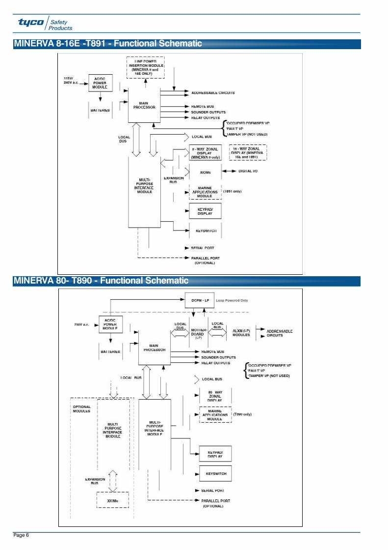
MINERVA 8-16E -T891 - Functional Schematic
MINERVA 80- T890 - Functional Schematic

Page 7
The Multi-Purpose Interface Module [MPIM] ismounted on the rear of the front cover assemblyand is used to provide interface facilities betweenthe main processor card [MP] and a number ofdifferent peripherals. An MPIM must have its'Personality' [configuration] set by means of plug-in headers to suit the particular application andset the device address. The board can perform anumber of functions, each 'Personality' being adifferent combination of these functions.
All MPIMs come fitted with Version 3.2 firmwareand a separate product code is available forupgrades - refer to TIB 0360 if necessary.
All MPIMs come fitted with a PROM (557.180.052)which enables an MPIM to be used with a serialprinter. If retrofitting a MPIM without this PROM,for use with a remote printer, this chip is required.
Product Codes557.180.012MINERVA Multi Purpose Interface Module [MPIM]
557.180.052MINERVA serial printer driver kit (Spare)
Multi Purpose Interface Module (MPIM)
Input/Output Expansion Cards (XIOM)
The XIOMis a 16 universal input/outputexpansion board. Up to 5 x XIOM cards can bedriven from each MPIM subject to its personalitysettings.
The I/O on the XIOM can be set in banks of 8 tooperate as follows:• LED driver outputs (10mA source)• Relay Driver Outputs (100mA sink)• Voltage Monitor Input (8 - 30Vd.c. Normal)• Volt Free Contact inputsTechnical SpecificationDimensions: 144H x 85W x 15D mm
Operating Temp: -10 to +65°CStorage Temp: -20 to +65°C
Relative Humidity: 95% RH (Non-Condensing)
Product Code557.180.016XIOM MINERVA Input/Output Expansion Modul16Way
MINERVA RepeatersThe MINERVA fully functional repeaters areavailable for all models of the MINERVA seriescontrollers. The repeaters are LPCB approvedand offer the same control and monitoringfacilities as the main panel. Each repeaterincludes one MPIM Module and up to sevenrepeaters can be attached to the remote bus ofthe main panel.The technical specification for the repeater is thesame as the main panel shown on the previouspage, product codes are also shown there.
The 80-Way Mimic allows custom-made displayand presentation panels to be incorporated in
the MINERVA addressable system. It is suppliedas a single PCB, which may be mounted in anexpansion box or on the rear of a free-standingpanel, as required. It may be used to drive up to80 zonal LED indicators, arranged in anyconfiguration, together with two FIRE LEDs, oneFAULT LED and one ISOLATE LED. Theseindicators operate in the same manner as thecorresponding indicators on the panel.A remote Mimic can be connected to the MPIM’sconfigured as remote Mimic drivers via theremote bus. Up to 16 MPIMs may be connectedon to the remote bus, each with a unique address[set on-board]. The difference between a
Repeater and a Mimic is the local control facilitywhich is not featured in a Mimic. Both Repeaterand Mimic include audible and visible warningfacilities.Technical SpecificationDimensions: 235H x 190W mmOperating Temp: -10°C to +55°C
Storage Temp: -20°C to +65°C
Relative Humidity: Up to 95% RH Non Condensing
Product Code557.180.005MINERVA 80-Way Mimic Driver Module
Remote Mimics
Datasheet - Product Code PB56 “Minerva 8, 16, 16E, 80 Panels” Manual - Vol015A-02-D1 “Minerva Range of Analogue Addressable Fire Controllers”
The DC/DC Converter produces regulated d.c.supplies from the ACPM outputs for use by thepanel logic circuits. The DC/DC Converter isnormally supplied only with MINERVA 80 and isfitted into the panel housing. A special version isavailable for loop powered MINERVA systems. An additional DC/DC converter may be used tosupply power to two additional MPIM cards.
Product Codes557.180.051MINERVA DC/DC converter module557.180.205MINERVA loop power DC/DC converter module
DC/DC Converter (DCCM)
MINERVA - Auxiliary Expansion Outputs

Page 8
The Remote LCD Repeater Module is designed toprovide an independent scrolling log of systemstatus at numerous points within a building orsite. The module interfaces directly to a serialprinter port of the MINERVA addressable firepanel. If a local printer is already connected tothe Panel's MPIM serial port, a second MPIMmust be used.Features· Uses a back-lit 4x20 character alphanumeric
display• Provides an internal log of up to 150 events• Provides internal audible warning of an event• Allows the event log to be scrolled• Local internal buzzer silence• Connects to host panel's RS232 port
(maximum cable length between panel andfirst repeater of 15m)
• Provides an external sounder to mimic theinternal buzzer
• Can be connected to an unlimited number ofother LCD Repeaters by using theRS232/RS422 converter (up to 1200mbetween repeaters)
The LCD repeater must not be used in theprimary fire path. It must not be used as the solewarning that a fire exists.
Technical SpecificationD i m e n s i o n s : 150H x 200W x 75D mmM a t e r i a l : Bayblend
p o l y c a r b o n a t e / A BS alloy
Operating Te m p : -10°C to +55°C
Relative Humidity: Up to 95% RH non-c o n d e n s i n g
Power Supply: 200mA @24Vd.c.Ext. Sounder relay: 500mA @24Vd.c.
E M C: BS EN50081-1 and 50082-1
Product Codes5 5 7 . 1 8 0 . 0 3 5 . ARemote LCD Repeater - ADT branded
5 5 7 . 1 8 0 . 0 3 5 . TRemote LCD Repeater - Thorn branded
5 5 7 . 1 8 0 . 0 6 2M I N E R VA MPIM to printer lead (D type 25 way male)
5 5 7 . 1 8 0 . 6 6 7M I N E R VA MPIM to printer/PC lead (D type 9 wayf e m a l e )5 5 7 . 1 8 0 . 1 5 29 way gender changer for 557.180.667
5 5 7 . 1 8 0 . 1 5 1RS232/422 converter for LCD Repeaters
Remote LCD Displays
LOCAL PRINTERA serial port is also available from the controller'sMPIM, which may be used to drive a serial printeror a terminal/computer. In cases where more thanone printer is required locally, it is possible to"piggy-back" an additional MPIM onto the MPIMon the front panel and this will, when connectedto the local bus, provide the interfaces (up to amax of 8) for additional (printer) equipment.
REMOTE PRINTERIf it is required to have printers positioned at aremote location, an MPIM must be used. ThisMPIM has its address set on-board and isconnected to the controller's remote bus. Theconnections between a MINERVA controller andremote printers are shown in the diagram below.An additional DC/DC converter module wouldtypically be required to power the MPIM (theDC/DC converter can power two MPIM cards).
WALL MOUNTED PRINTERThis unit is designed to provide a wall-mountedprinting facility for the MINERVA analogueaddressable fire control panels. The unit ispowered from 240V a.c. 50Hz and uses a 42column printer with an RS232 serial input. It isdesigned primarily as a hard copy alarm/faultlogging facility. A serial printer cable is used toconnect the printer to an MPIM configured as aprinter driver.Technical SpecificationDimensions: 320H x 170W x 140D mm
Colour: Dawn GreyOperating Temp: 0°C to 40°C
Storage Temp: -15°C to 40°CRelative Humidity: 10% to 90% RH
[non-condensing]
EMC: BS EN 50081-1 and BS EN 50082-1
Operating Voltage: 180V to 264V a.c.Protection: External 2 Amp fuse
Power: 20W
WARNING:The mains supply must be from thesame source as the MINERVA control panel andbe isolated by the same device. The serial printercable must be run in metal conduit to comply withthe EU EMC Directive (89/336/EEC).Product Codes557.180.076.AMINERVA Wall Mounted Printer (ADT branded)
557.180.076.TMINERVA Wall Mounted Printer (Thorn branded)557.180.202MINERVA MPIM to printer (wall mounted) lead(right angled D type 25 way male)
557.180.079Bezel for flush wall mounted printer
557.180.223MINERVA wall mounting printing ribbon (Spare)
557.180.052MINERVA Serial Printer driver kit509.022.008Spare printer paper
MINERVA Printer Options
The AC Power Module [ACPM] is common to allMINERVA addressable models and suppliespower to all the PCBs and other devices fitted. Itcontains an integral battery charger whichcontinuously charges back-up batteries. Theseare required to supply the system in the event ofa mains failure, in order to comply with the
requirements of BS 5839 Part 1 [1988].
Addressable versions of the ACPM are available.This unit reports fault conditions to the controlpanel via the addressable loop.Technical SpecificationHousing Dimensions: 320H x 400W x 140D mmColour: Dawn GreyOperating Temp: -10 to +55°C
Storage Temp: -20 to +65°CHumidity: Up to 95% RH non-
condensingHousing Protection: IP43Mains Supply: 110-120/220-240Va.c. ±10%
50/60Hz ±5%Charger Current: 2.7A @27.6Vd.c.Product Codes557.180.001MINERVA power module - non addressableACPM557.180.561MINERVA surface mounting power box completewith non addressable ACPM557.180.002MINERVA power module - addressable ACPM557.180.560MINERVA surface mounting box complete withaddressable ACPM
AC Power Module (ACPM)
Page 9
The MINERVA pager system is designed toprovide a facility to signal all text messages oralarm/fault messages from a local transmitter tothe pagers.
The transmitter connects to the serial printer portof an MPIM, if a local printer is connected to the
controllers MPIM serial port, a second MPIM mustbe used. The pager system requires a +12V d.c.connection (from the MINERVA) and a serial portconnection. If the transmitter needs to be locatedfurther than 2 m from the MINERVA, then a non-standard serial printer cable may be used, up to amaximum distance of 14m.CAUTION: Before any installation is carried out, anon site radio paging license must be obtained bythe customer. Care should be taken whendesigning pager systems. Normal practiceindicates that a site survey should be done.Contact Product Management for additional adviseon site surveys.The Type A alarm pager can display alarm/faultmessages. The Type A maintenance pagerdisplays all messages sent by MINERVA.
The pagers:-• Display messages sent out by the MINERVA as
displayed on the Minerva LCD• Internal log of up to 40 events• Audible and/or vibrate warning of event• Allows the event log to be displayed.The transmitter:-• Connects using a 9way D type MINERVA
interface lead• Can be setup for transmission to Type A• Using standard aerial, provides a 500 metre
sphere of transmission in open air
Technical SpecificationDimensions: 328H x 190W x 75D mm
System operating voltage: 12 to 13.8 Vd.c.
Effective radiated power: 500mWFrequency range: 50-470 MHz
Channel spacing: 25KHz
TX baud rate: 512 or 1200Type approval ETS 300 224, MPT1383 Cert No13249, EC type approved to ETS 300 682Approval No. 13331
Product Codes577.002.001Pager Transmitter
577.002.002Type A alarm pager
577.002.003Type A maintenance pager577.002.007Pager aerial 60 db gain up to 1km
577.002.008Optional feeder cable
Manual - Vol08A-05-D1 “Ancillaries Manual”
Pager Interface
The function of the Consys configuration softwareis to customise a MINERVA addressable panelsystem to the requirements of the customer.Configuration is performed on the basis of dataobtained from the customer. This data shouldhave been documented by the system designerusing form 180 (available from the website) andincludes the following information:• The number and location of detectors and
other ancillaries.• The addresses of the above devices• The 'zoning' requirements• The number and location of any interface
boards• The addresses of the above boards• Bell mapping options• Co-Incidence grouping• System fire options• Network configurationThis information is fed into 'CONSYS' and storedon a floppy disk. This disk can be used with alaptop computer and downloaded into the panelvia a download lead. Most laptop computers have9 way serial comms ports, but sometimes onemay require a 25 way serial download lead. A"dongled" variant of Consys exists which onlypermits Consys to be installed on PCs with adongle. Additionally variants also exist which
restrict access to Consys features i.e. customerand distributor variants.A number of Consys variants are available e.g.UK (non-dongled), UK dongled, UK Customer, UKdistributor, US (non-dongled), Dutch (non-dongled), Marine (dongled). Registered copies of the Consys configurationsoftware are available from the technicaldistribution department, Walthamstow, LondonE17 Tel +44 (0) 208 919 4004.Datasheet - Product Code PB56 “Minerva 8, 16,16E, 80 Panels” Manual - Vol015A-02-D1 “Minerva Range ofAnalogue Addressable Fire Controllers” andVol011A-01-XX “Software Operating Manual”
Product Codes557.180.063MINERVA MPIM to PC (D25) serial lead assembly 557.180.667MINERVA MPIM to PC (D9) serial lead557.180.105MINERVA full CONSYS software key (dongle)557.180.106MINERVA customer/distributor software key(dongle)557.180.234Customer CONSYS pack vers 12.1
MINERVA CONSYS and Firmware
FirmwareUpgrade M16E M80 ALXMVer 12.0 557.180.831 557.180.832 557.180.833Ver 12.1 557.180.155 557.180.156 557.180.157Ver 12.2 557.180.159 557.180.160 557.180.161Ver 12.3 557.180.163 557.180.164 557.180.165Ver 12.4 557.180.167 557.180.168 557.180.169
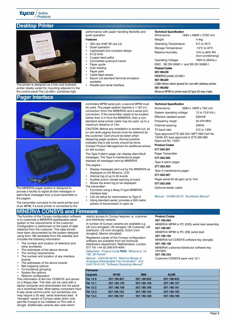
The printer is designed as a low cost businessprinter ideally suited for mounting adjacent to thefire control panel.The LQ-300+ combines high
performance with paper handling flexibility andquiet operation.
Features• 300 cps draft/ 90 cps LQ.• Quiet operation• Lightweight and compact design• 9 LQ fonts• 2 paper feed paths• Convertible push/pull tractor• Paper guide• Auto loading• Paper park• Cable feed recess• Epson LQ standard terminal emulation
available• Parallel and serial interface
Technical SpecificationDimensions: 159H x 366W x 275D mm
Weight: 4.4kg
Operating Temperature: 5°C to 35°CStorage Temperature: -15°C to 40°C
Relative Humidity: 10% to 80% RH [non-condensing]
Operating Voltage: 180V to 264Va.c.EMC: BS EN 50081-1 and BS EN 50082-1Product Codes5 5 7 . 1 8 0 . 23 9M I N E R VA printer LQ- 3 0 0 +5 5 7 . 1 8 0 . 2 2 0LQ80 ribbon black (spare) for use with desktop printer.5 5 7 . 1 8 0 . 0 6 2Minerva MPIM to printer lead (D type 25-way male)
Desktop Printer

Page 10
MINERVA panels are supplied with a housing.Matching dawn grey housings are available forhousing other equipment along side theMINERVA panel. The general purpose housing isavailable in surface and flush models withmatching diecast door.
Other housing options include the terminalchamber PCB which provides neat terminationsfor addressable loop field wiring.The optional gland cover provides a neatinstallation for the surface mount installations andthe 19˝ rack mount kit allows the surface mountMINERVA panel or general purpose housing tobe fitted in a 19˝ rack.
Product Codes557.180.033MINERVA general purpose housing flush
Housings
557.180.021MINERVA plain cover assembly for use withgeneral purpose housings - see below
557.180.022MINERVA terminal chamber PCB assembly
557.180.032MINERVA general purpose housing surface
557.180.034MINERVA expansion housing surface
557.180.452MINERVA Marine 19"rack mounting kit for use withsurface mounting housings
The following additional items are available asstandard spares. Other components can besupplied as specials.
Product Codes555.180.002MINERVA 16E front cover assembly
557.180.408 (Available on BSO)
T890 Front cover assembly555.180.003MINERVA 80 front cover assembly
557.180.407 (Available on BSO)T891 Front cover assembly
557.180.010MINERVA 80 motherboard PCB
557.180.054MINERVA 16 mounting plate kit
557.180.200MINERVA main processor PCB no software fitted
557.180.204Motherboard loop powered for use with MINERVA80 (spare)557.180.209Keyswitch assembly for use with MINERVAcontrollers (spare)
557.180.208MINERVA spare keys (used on MINERVAcontrollers mid '94 Onwards)
557.180.722MINERVA 80 cover assembly dutch (spare)
Datasheet - Product Code PB56 “Minerva 8, 16,16E, 80 Panels” Manual - Vol015A-02-D1 “Minerva Range ofAnalogue Addressable Fire Controllers”
MINERVA Spares
Marine Housing Options 557.180.406 MINERVA Marine Terminal Chamber
557.180.410 MINERVA Marine Battery Fitting Kit557.180.454 MINERVA Marine Bulkhead Mount
Datasheet - Product Code PB56 “Minerva 8, 16,16E, 80 Panels” Manual - Vol015A-02-D1 “Minerva Range ofAnalogue Addressable Fire Controllers”

Page 11
An extensive range of ancillary modules has beenspecifically designed for use with the MINERVA 8,16E and 80 range of Fire Control Panels. TheM520 range of ancillary modules provide theMINERVA Panel with a wide degree of systemsapplication flexibility. This allows the fieldaddressable loop from the control panel to bothreceive inputs to the system and control outputsfrom it.
This broad range of modules allows the scope ofthe fire detection system to be significantlyextended beyond a simple fire detector - alarmsounder based alarm system. The commandmodules enable fire doors to be closed, fire
dampers to be controlled, provide an interface toshut down HVAC equipment. Other applicationsinclude an interface between shopping centretenants' premises and the landlords' centralcontrol system.
With the high systems integrity offered on theMINERVA Panel the command modules can alsobe used to control a public address basedbuilding evacuation system.Features• Communications and control interface to
MINERVA Fire Panels• High Systems Integrity• Allows remote sounder circuits
• Allows loop powering of sounders and/orbeam detector units
• Monitoring of external equipment, e.g. smokedampers
• Reduced installation cost• Removes the need for separate plant control
circuits
Datasheet - Product Code PSF86 “520 SeriesAncillary Equipment” (unless otherwise indicated). Manual - Vol08A-02-D* “Ancillaries Manual” * Design section indicated next to product code.
The LI520 Mk2 line isolator is used to ensure thata short circuit fault on the addressable loop willnot cause a total systems failure. LI520 Mk2'seffectively contain the fault to specific areas of the
loop. Line isolators should be used at theboundary of each zone so that no more than asingle zone is made inoperative during a shortcircuit condition. This feature is a requirement ofBS5839 Part 1 1988. The LI520 Mk2 is also fittedwith a amber LED to indicate locally when theisolator has been tripped.
The maximum number of line isolators perMINERVA loop is 12. There are also two isolatorcircuits built into the MINERVA control panel loopdrivers (one for each end of the loop).
The LI520 Mk2 takes its operating power from theMINERVA loop.The module is not addressable and will thereforenot take an address on the loop.
Technical SpecificationPowered: Loop
Temperature Range: -10°C to 70°COperating Humidity: up to 95% RH non-
condensing
Dimensions: 60H x 84W x 14D mm
Product Codes545.001.007MINERVA LI520 Mk2 line Isolator module
545.001.009LI520/M520 line isolator and cover assembled
Manual - Vol08A-02-D20 “Ancillaries Manual
LI520 MK2- Line Isolator Module
The CM520 module provides the facility tomonitor an external contact, e.g. fire door monitor.This monitored point can then be used as acontrol input for the MINERVA panel which isactivated when the monitored contact is eitheropen or closed. A delay between the monitoredcontact opening/closing and the activation of thecontrol input can be specified within the controlpanel settings. The CM520 takes its operatingpower from the MINERVA loop. The module isaddressable and will therefore take one addresson the loop.
Technical Specification
Powered: LoopTemperature Range: -10°C to 70°COperating Humidity: up to 95% RH non-
condensingDimensions: 60H x 84W x 14D mmProduct Codes (Vol08A-02-D3)555.180.021CM520 contact monitor module (1 input)555.180.026CM520/M520 contact module and coverassembled
CM520 - Contact Monitoring Module
The TM520 provides an output that can beactivated based on a delay time. If either the key-switch on the module is activated, or a predefinedevent within the control panel occurs then a timeddelay (set between 10 minutes and 21 hours 10minutes) is started. When the delay reaches zerothe TM520 output is activated. The unit sounds aninternal buzzer and shows a red LED when theoutput is active, and shows a yellow LED whenthe timer is counting down. To provide a warningthat the delay is nearly over, the red LED and thebuzzer will pulse 5 minutes before the end of thedelay .
The TM520 requires a separate 24Vd.c. supply tooperate. The module is not addressable and willtherefore not take an address on the loop.
Technical SpecificationPowered: 24Vd.c.Temperature Range: -10°C to 70°COperating Humidity: up to 95% RH non-
condensingDimensions: 87H x148W x 14D mmProduct Code (Vol08A-02-D16)557.180.423TM520 timer module - non addressable
TM520 - Timer Module
The RM520 provides one volt-free change-overrelay contact rated at 1A @ 24Vd.c. Commandsignals to drive the relay are configured in theMINERVA control panel software with the triggerpoint being defined as a detector or other eventprogrammed into the system. The relay contactsare monitored and the state (activated/de-activated) is reported back to the control panel.The RM520 is also fitted with a red LED toindicate locally when the relay is operated.Typical applications for the RM520 include firedoor control or lift control. The RM520 takes itsoperating power from the MINERVA loop. Themodule is addressable and will therefore take oneaddress on the loop.
Technical SpecificationPowered: Loop
Temperature Range: -10°C to 70°C
Operating Humidity: up to 95% RH non-condensing
Dimensions: 60H x 84W x 14D mm
Product Codes (Vol08A-02-D1)568.001.011RM520 relay module (1 x 24Vd.c. rated relay)
568.001.017RM520/M520 relay module and cover assembly
RM520 - Relay Module
MINERV A Addressable Modules

Page 12
The DM520 is used to interface a single zone ofconventional detectors onto the MINERVAanalogue addressable loop. This provides a costeffective and easy method of extending existingconventional systems or a future upgrade path fornew conventional systems. The DM520 is alsofitted with a red LED to indicate locally when theassociated conventional zone has entered analarm condition. The DM520 requires a separate24V d.c. supply to operate. The module isaddressable and will therefore take one addresson the loop.
Technical SpecificationPowered: 24V d.c.
Temperature Range: -10°C to 70°COperating Humidity: up to 95% RH non-
condensing
Dimensions: 60H x 84W x 14D mmProduct Code (Vol08A-02-D2)517.035.012DM520 conventional detector module517.035.018DM520/M520 detector module and coverassembled
DM520 - Conventional Detector Module
The MDM521 module is used to interfaceconventional detection zones onto the MINERVAanalogue addressable loop in a similar way to theDM520. The MDM521, however, can beconfigured to interface up to 8 zones ofconventional detectors rather than the DM520'ssingle zone. The module has an LED for each ofthe 8 zones which will show red when the zone isin alarm and yellow if the zone is in fault. Thismodule provides a cost effective method ofinterfacing several conventional zones onto anaddressable loop. The MDM521 requires a separate 24Vd.c. supply
to operate. The module is addressable and willtake as many addresses as there are zones beingmonitored (i.e. between 1 and 8).Technical SpecificationPowered: 24Vd.c.Temperature Range: -10°C to 70°COperating Humidity: up to 95% RH non-
condensingDimensions: 290H x 88W x 30D mmProduct Code (Vol08A-02-D25)517.035.017MDM521 Multi circuit conventional detectormodule
MDM521 - Multi-DM Module
The SM520 module is used to provide an outputto alarm sounders or visual warning devices inresponse to a control signal from the controlpanel. The devices are controlled directly from theSM520 on the addressable loop rather than fromoutputs on the control panel, thereby significantlyreducing wiring costs. The output wiring to thealarm devices is fully monitored and the modulehas the capability to drive up to a maximum of500mA alarm device load. If higher alarm deviceloads are required then an SB520 sounderbooster module must be used in conjunction withthe SM520. The SM520 requires a separate24Vd.c. supply to operate. The module isaddressable and will therefore take one addresson the loop.
Technical SpecificationPowered 24Vd.c.Temperature Range -10°C to 70°COperating Humidity up to 95% RH non-
condensingDimensions 60H x 84W x 14D mmAlarm load max: 24Vd.c. @500mAProduct Code (Vol08A-02-D6)577.001.022SM520 sounder driver module577.001.032SM520/M520 sounder module and coverassembled
SM520 - Sounder Driver Module
The SB520 sounder booster module is used inconjunction with the standard SM520 to drive oneor more alarm sounder devices from theaddressable loop rather than directly from controlpanel outputs. The SB520 is required when thealarm sounder load to be driven from the SM520is greater than 500mA. Using the SB520increases the sounder load capacity to 15A.
The SB520 requires a separate 24Vd.c. supply tooperate. The module is not addressable and willtherefore not take an address on the loop.
Technical SpecificationPowered: 24Vd.c.Temperature Range: -10°C to 70°COperating Humidity: up to 95% RH non-
condensingDimensions: 60H x 84W x 14D mmAlarm load max: 24Vd.c. 15AProduct Code (Vol08A-02-D7)577.001.023SB520 sounder booster module577.001.033SB520/M520 sounder booster module and coverassembled
SB520 - Sounder Booster Module
The LPS520 module provides control outputs foralarm sounders in the same way as the SM520module, except that no external power supply isrequired as the sounders draw their powerdirectly from the addressable loop. A maximum of4 LPS520 modules can be used per loop, eachdriving a maximum of 6 Banshee sounders.
The LPS520 takes its operating power from theMINERVA loop.
The module is addressable and will therefore takeone address on the loop.
Technical SpecificationPowered: Loop
Temperature Range: -10°C to 70°COperating Humidity: up to 95% RH non-
condensing
Dimensions: 60H x 84W x 14D mm
Product Code (Vol08A-02-D19)577.001.027LPS520 Loop powered sounder module
LPS520 - Loop Powered Sounder Module

Page 13
The AM921 module is used as an interfacebetween the MINERVA control panel and theLaserPLUS and Scanner aspirating detectors. The module is fitted inside the aspiratingdetectors housing at the relay output location andalso takes its power from the detector unit.
The module is addressable and will therefore takeone address on the loop.Technical SpecificationPowered: Loop
Temperature Range: -10°C to 70°C Operating Humidity: up to 95% RH non-
condensing
Dimensions 921: Fits in VLS/VLP
Product Code (Vol08A-02-D33)546.004.007AM921 aspirating interface module
AM921 Addressable Aspirating Interface
The Plant Interface module is an addressable,multi input/output device that is used to interfaceplant equipment to the MINERVA control panel.Inputs can be used for plant monitoring whilst theoutputs can be driven from the MINERVA controlpanel as required.
The module is configured in one of three Modes:
PI521/2 2 inputs and 2 outputs (Takes 4addresses on the loop; max per loop is 24) PI521/4 4 inputs and 4 outputs (Takes 8addresses on the loop; max per loop is 12)
PI521/6 6 inputs and 6 outputs (Takes 12addresses on the loop; max per loop is 8)
All outputs are rated at 240V 5A. The PI521requires a separate 24Vd.c. supply to operate.
Technical SpecificationPowered: 24Vd.c.Temperature Range: -10°C to 70°COperating Humidity: up to 95% RH non-
condensingDimensions: 72H x 245W x 23D mmProduct Codes (Vol08A-02-D18)546.004.006PI521 MINERVA plant interface module547.004.001DIN rail mounting kit
PI521 - Plant Interface Module
The SD520 provides two monitored inputs andone relay output rated at 240V @ 5A. The SD520is ideally suited to driving smoke damper unitsdirectly from the MINERVA loop. One of theinputs can optionally be used to monitor theaction of the module relay externally, i.e. at thesmoke damper unit. The SD520 is fitted with a redLED to indicate locally when the relay is operated.
The SD520 requires a separate 24V d.c. supply tooperate. The module is addressable and willtherefore take one address on the loop.
Technical SpecificationPowered 24Vd.c.Temperature Range -10°C to 70°COperating Humidity up to 95% RH non-
condensingDimensions: 60H x 84W x 14D mmRelay output rating: 240Va.c. @ 5AProduct Code (Vol08A-02-D17)568.001.014SD520 smoke damper interface module ( 2 inputsand 1 output)
SD520 - Smoke Damper Interface Module
The LPBD521 module is used to drive the FireRay2000 beam detector units directly from theMINERVA loop. A single LPBD521 can be used to
power the analyser unit, the beam receiver unitand the transmitter unit. Alternatively, twoseparate LPBD521's can be used with one topower the analyser unit and receiver units and thesecond to drive the transmitter separately, eitherfrom the same loop or a different loop. Up to 8LPBD521's can be used per loop.
The module is addressable and will therefore takeone address on the loop.Technical SpecificationPowered Loop
Temperature Range -10°C to 70°COperating Humidity up to 95% RH non-
condensing
Dimensions: 60H x 84W x 14D mm
Product Code557.180.217LPBD521 loop powered beam detector interfacemodule for use with FireRay 2000
Datasheet - Product Code PSF85 “Fireray 2000Optical Beam Smoke Detector” Manual - Vol08A-02-D26 “520 Series AncillaryEquipment”
LPBD521 - Loop Powered Beam Detectors

Page 14
The SU251 is an addressable, multi input/outputdevice that is used to interface other fire orsecurity systems into the MINERVA control panel.Inputs can be used for taking signals from othersystems (e.g. taking individual shop securitysystems into the central shopping centre system)whilst the outputs can be used to send controlsignals from the MINERVA back to the individualtenant's system. The SU521 can be configured inone of three formats:SU521/2 2 inputs and 2 outputs (Takes 4addresses on the loop; max per loop is 24)
SU521/4 4 inputs and 4 outputs (Takes 8addresses on the loop; max per loop is 12)
SU521/6 6 inputs and 6 outputs (Takes 12addresses on the loop; max per loop is 8)
All outputs are change-over contacts rated at 24V1A. The SU521 takes its operating power fromthe MINERVA loop.Technical SpecificationPowered: Loop (0.54mA)
Temperature Range: -10°C to 70°COperating Humidity: up to 95% RH non-
condensing
Dimensions: 72H x 245W x 17D mmProduct Codes (Vol08A-02-D15)568.001.013SU521 shop unit interface module547.004.001Din rail mounting kit
SU521 - Shop Interface Module
Round address labels are used for fixing toaddressable devices and are provided in 10different colours to allow differentiation betweenloop wiring.Product CodesRound Labels599.047.001Label loop A white
599.047.002Label loop B yellow
599.047.003Label loop C purple
599.047.004Label loop D green599.047.005Label-loop E grey 599.047.006Label-loop F blue
599.047.007Label loop G orange
599.047.008Label loop H red599.047.009Label loop I dark blue
599.047.010Label loop J black
Zone labels are affixed to address labels toproduce a combined address/zone label.
Product CodesZone Labels599.047.011Label zones 1-16
599.047.012Label zones 17-32599.047.013Label-zones 33-48
599.047.014Label-zones 49-64
599.047.015Label-zones 65-80
Minerva Loop and Zone Labelling
Most M520 modules can be fitted to a doublegang MK style backbox using the M520 ancillarycover. Where several devices are mounted in oneplace the ANC3 houses 3 x M520 modules andthe ANC8 houses 8 modules, expandable to 16using the STK8 stacking kit.
Product Codes517.035.007M520 Ancillary cover for use with M520 modules557.180.096.AANC-8 MINERVA ancillary housing ADT Branded
557.180.096.TANC-8 MINERVA ancillary housing ThornBranded557.180.095STK-8 MINERVA ancillary stacking kit for use withancillary housing 557.180.096
557.180.097.A (Vol08A-02-D18)ANC-3 MINERVA ancillary housing ADT Branded
557.180.097.T (Vol08A-02-D18)ANC-3 MINERVA ancillary housing ThornBranded (See picture)
Ancillary Covers and Housings
Page 15
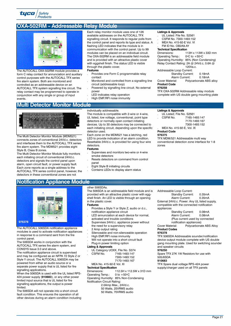
The AUTOCALL TFX-500M, TFX-800M, TFX-500MVand TFX-800MV comprise the AUTOCALL TFXfamily of self contained Fire Alarm Control Panels.CALL TFX-500M provides up to 198 analogueaddressable initiating and output devices, whilethe AUTOCALL TFX-800M expands the capacity to990 devices. The basic system hardware andsoftware is common for both AUTOCALL TFX-500M and TFX-800M, therefore the 500M can beexpanded to 800M on site.AUTOCALL TFX controls are designed to be usedwith conventional or analogue addressable firedetection devices, in any combination thereof.Engineered with advanced microprocessortechnology, these fire control panels provide adynamic level of applications flexibility. Theexclusive CONSYS software configuration tool forsite specific user programming easily guides thetrained installer through a menu prompteddecision process.
Features. Conventional and analogue addressable fire
detection. 198 Analogue addressable initiating and
output devices plus 1600 discrete inputs oroutputs (TFX-500M)
. 990 Analogue addressable initiating andoutput devices plus 1100 discrete inputs oroutputs (TFX-800M)
. TFX-500M may be expanded to TFX-800M onsite
. 80 Character LCD display; 40 user definedmessage characters
. Power limited, all circuits
. Integral LED zonal or group annunciator
. Degrade mode in TFX-800M operatesevacuation signals if CPU failure occurs beforeor during an alarm
. Smoke detector condition monitoring withautomatic environmental compensation
. Individual smoke detector sensitivity selectablefrom the operator interface
. Historical event log for view or print
. Fully site programmable
. Solo test and alarm verification per group orpoint
. Automatic time control functions with holidayexceptions
. Six access levels with unique 0911 FireDepartment Access
. Automatic and manual detector sensitivityadjustment
. Alarm resound by zone or device
. Modular, expandable
. Single, dual and multi-channel voice systems,25 and 70 VRMS
. Networking capability to the graphical userinterface from any TFX panel.
Listings & Approvals. UL 864 Listed for Local, Auxiliary, Remote
Station and Proprietary Receiving StationService; File S2561
. CSFM No. 7165-0062:161
. MEA No. 415-92-E
. FM ID No. OX2A8.AYNOTE: AUTOCALL TFX-500M and TFX-800M areintended for use within a building interior, free fromexposure to moisture, condensation and excessivedust.Technical SpecificationTemperature Range: 0oC to 49oCRelative Humidity: 85% Non CondensingLoop Styles: NFPA 72 Style 4 and 6. Lineisolators optional for short circuit isolationMax. Add. Per Loop: 99Max. Loops Per Sys: 2 (TFX-500M)
10 (TFX-800MVoltage: 26Vd.c., 300mASupervisory Current: 20mA per loop (plus load)Alarm Current: 24mA per loop (plus load)Resistance: Max 75 OhmsCapacitance: Max. 0.5 microfarad (mutual)Inductance: Max. 1.5 millihenry (total)Max. Continuous Dis: 6500 feetProduct Codes557.180.623TFX-500M 2 loop fire control panel with redarchitectural door. Grinnell branded in 3 tierhousing with FCM/OCM and 16 LED indicator.Supplied complete with 4” shallow backbox.Other colours and branding available on request.557.180.624TFX-800M Fire detection panel with redarchitectural door and Grinnell branding in 7 tierhousing with FCM/ODM and 80 LED indicator.Supplied prebuilt complete with 6” backbox.Other colours and branding available on request.
Analogue Addressable TFX-500/800 Series
Addressable Fire Systems - UL/FM Approved
557.180.624
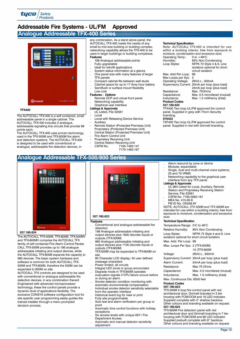
The AUTOCALL TFX-400 is a self contained, smalladdressable panel in a single cabinet. TheAUTOCALL TFX-400 includes 2 analogue,addressable signalling line circuits that provide 99points each.The AUTOCALL TFX-400 uses proven technology,used in the TFX-500M and TFX-800M fire alarmand detection systems. The AUTOCALL TFX-400is designed to be used with conventional oranalogue, addressable fire detection devices, in
any combination. As a stand alone panel, theAUTOCALL TFX-400 meets the needs of anysmall-to-mid size building or building complex;networking capability allows the TFX-400 to beused in larger buildings or building complexes.Features. 198 Analogue addressable points. Fully upgradable. Ideal for retrofit applications. System status information at a glance. One panel size with many features of larger
TFX panels. Compact cabinet fits between wall studs. Cabinet space for up to 17 Amp hour battery. Semiflush or surface mount flexibility. Low costFeatures - Options. Remote OCP and virtual front panel. Networking capability. Graphical user interfaceListings & Approvals. UL Listed, File S2561- Local- Local with Releasing Device Service- Auxiliary- Remote Station (Protected Premises Unit)
Proprietary (Protected Premises Unit)- Central Station (Protected Premises Unit)- Fire Alarm Control Unit- Proprietary Receiving Unit- Central Station Receiving Unit. CSFM No. 7165-1493:147
7170-1493:167
Technical SpecificationNote: A U T O C A L L T F X-400 is intended for usewithin a building interior, free from exposure tomoisture, condensation and excessive dust.Operating Temp.: 0 to +49oCHumidity: 85% Non-CondensingLoop Styles: NFPA 72 Style 4 & 6. Line
isolators optional for short circuit isolation
Max. Add Per Loop: 99Max Loops per Sys: 2Operating Voltage: 26Vd.c., 300mASupervisory Current: 20mA per loop (plus load)
24mA per loop (plus load)Resistance: Max. 75OhmsCapacitance: Max. 0.5 microfarad (mutual)Inductance: Max. 1.5 millihenry (total)Product Codes557.180.625TFX400 Two loop UL/FM approved fire controlpanel. Supplied in grey with Thorn Securitybranding.976422TXF400 Two loop UL/FM approved fire controlpanel. Supplied in red with Grinnell branding.
Analogue Addressable TFX-400 Series
TFX400
557.180.623

Page 16
Product Codes9976130TFX 40X2 Indicator with MPIM board. Provides anadditional 40X2 zone indicators for use with TFX-500M or TFX-800M9976132TFX 40 Way status control module and MPIMmodule for adding to TFX-500M or TFX-800M9976134TFX 16 Way status control module with MPIM foruse with TFX-500M or TFX-800M
9976136TFX 80 Indicator module with one integral MPIMcard for use on TFX-800M9976137TFX 80 Way Indicator module with 2 MPIMmodules built in
TFX Additional User Interface Module
The Remote Operator Control Panel (remote OCP)is designed for use with the AUTOCALL TFXseries systems to provide system operatingcontrols at a remote location. The unit is suitablefor mounting in lobbies, vestibules or anywherewere space is a premium. Three configurationsare available and each are housed in small,attractive units, finished in red with a blackfaceplate. Each configuration is suitable for indoorsemiflush or indoor surface mounting.All remote OCP configurations contain a firecontrol module (FCM) to duplicate basic fire alarmfunctions at a remote location. Control buttonswith LEDs for panel silence, alarm silence, systemreset, and drill are furnished. Labels for eachcontrol button may be field customised inlanguages other than English, or to meet on siterequirements. A lamp test button is also provided.LEDs for fire alarm, supervisory, fault and isolateannunciation are furnished. A separate LED forpower on indication is also provided. In addition,three programmable LEDs are available forannunciation of programmed actions.The Remote OCP is also available with either anoperator display module (ODM) or a 16 indicatormodule.The optional ODM provides an 80 character,backlit alpha-numeric, LCD operator display. TheLCD provides user defined text messages of eventtype and precise location. An operator’s keypadallows the user to acknowledge events, makeinquiries, and view system status. The real timeclock and date settings are set and changed fromthe keypad as well. All control functions are
password protected.Functions available at the ODM include:. Per point annunciation of alarm and trouble
events. View and acknowledge events which have not
been restored to normal. Force outputs on. View smoke detector analogue values in %
obscuration per foot, and perform sensitivitychecks, NFPA 72 requirements
. View event history log
. Isolate zones and points
. Enable Solo test mode
. Enable maintenance mode
. Print status and maintenance reports
. Change smoke detector sensitivityThe optional 16-indicator module provides fieldconfigurable LEDs for annunciation by zone,group, device type or point. Since LEDs are bi-coloured (red and yellow), each LED may beconfigured to annunciate alarm and trouble. Labelspace is provided with each LED for customidentification.Features. LEDs Fire alarm - red
Supervisory - yellowFault - yellowIsolate - yellowPower-on - green
. Enable key switch
. Panel silence button and LED - yellow
. Alarm Silence button and LED - yellow
. System reset button and LED - yellow
. Drill button and LED - red
. Three programmable LEDs - yellow
. Lamp Test
. Internal buzzerFeatures - Optional Fire Control Module. 7 Sockets which accept red, yellow or green
LEDs for special requirementsFeatures - Optional Operator Display Module. Alphanumeric display. Numeric touch pad. No/Delete button
. Scroll up button
. Scroll down button
. Yes/Enter button
. Quit button
. Fast access buttonFeatures - Optional 16-Indicator Module. Zone alarm LEDs - red. Zone trouble LEDs - yellowListings & Approvals. UL File No. S374. CSFM No. 7165-1493:147
7170-1493:167. MEA 415-92-E, Vol. IX. FM 3001053Technical SpecificationOperating Temp.: 0 to +50oCOperating Humidity: 85% Non-CondensingCurrent Draw:
Standby Current: 50mA (FCM)32mA (ODM)9mA (16-IM)
Alarm Current: 65mA (FCM)32mA (ODM)34mA (16-IM)
Product Codes976402TFX Remote operator control panel with firecontrol module (FCM) and operator displaymodule (ODM).976403TFX Remote operator control panel with firecontrol module and 16 indicator LED module(FCM/16IND).976404TFX Semi flush backbox for use with all remoteoperator control panels.976416TFX Surface mount backbox for use with anyremote operator control panel.
Remote Operator Control Panel
9976134
9976136/997137
9976130 9976132
Product Codes850509TFX500 & 800M Field wiring guide940577TFX/CONSYS Programming cable with DB9female connector CONSYS software available ondocument control. Contact Jonathan Gilbert -Product Management, Sunbury or Nick Wright -Technical Services, Walthamstow976254TFX Spare keys for use on TFX OCM and door
976262TFX SIM Serial interface module provides isolationto serial printers
TFX Panel Components & Spares

Page 17
The AUTOCALL Power supplies (models RPS-424and DCPM) are solid state electronic powersupplies which provide filtered regulated DCpower to the AUTOCALL TFX series fire alarmsystem. The RPS-424 converts 120Va.c. primarypower to 24Vd.c., 5Vd.c. and 15Vd.c. The DCPMconverts 24Vd.c. power from the RPS-424 to thesupply voltages necessary for the TFX family.The power supply monitor module (module500PSM) monitors the RPS-424 and providesvisual trouble indication of faults.Features - RPS-424. Converts 120Va.c. input power to d.c.
operating power. Charges and supervises batteries. Automatic transfer to battery during a.c. power
failure or brownout. Unique voltage booster feature for notification
purposes
Features - DCPM. Converts 24Vd.c. to voltages required by the
TFX family
Features - 500PSM. Provides visual indicators for RPS-424 power
supply faults. Mounts directly to RPS-424 power supply. Provides addressable interface to TFX data
circuitsListings & Approvals. UL 864 Listed, File No. S2561. CSFM No.:
7165-1493:147 & 7170-1493:167 (models RPS-424, 500PSM)7165-1493:162 (model RPS-424)7170-1493:168 (models DCPM, 500 PSM)
. MEA No.: 415-92-E, Vol. VI (models RPS-424, 500PSM and DCPM)
. FM ID No.: OY9A3.AY (models RPS-424, 500PSM)OX2A8.AY (model DCPM)
Product Codes910683TFX Spare dual voltage RPS-424 powersupply/charger used on all TFX panels976040TFX DCPM DC/DC convertor for use as a spare orwith additional MPIM modules976122TFX 500PSM Power supply monitor module
Power Supplies
Technical SpecificationRPS-424 500PSM
Dimensions 112.5H x 187.5W x 50D mm 123.5H x 56.25W x 25D mmInput Voltage 120/240Va.c., 50/60Hz 24Vd.c.Input Current 1.5A RMS 62mAOutput Circuits +24Vd.c.@4A (non resettable)* N/A(for panel connections only) +24Vd.c.@2A (resettable)* N/A
+15Vd.c.@100mA* N/A+5Vd.c.@4A* N/A
Output Circuits +24Vd.c.@2A (non resettable)* +24Vd.c.@4A(for field connections only) +24Vd.c.@2A (resettable)* +12Vd.c.@100mA
N/A +5Vd.c.@4AOutput Voltage 24Vd.c. regulated (+10%/-5%) N/ASupervisory Current Draw 100mA (unloaded) 62mAAlarm Current Draw 100mA (unloaded) 62mA
* Total of output circuits must not exceed 5A alarm, 2.5A supervisory
976122 976040
910683

Page 18
The AUTOCALL Multi Purpose Interface Module(MPIM) is the communication interface betweenthe AUTOCALL TFX control panel and certainremote system functions. MPIMs communicatewith the main processor module through thesystem’s local or remote (RS485) bus. Each MPIMmodule is assigned a unique bus address bymeans of programming jumpers.The MPIM mounts in the AUTOCALL TFX panelenclosure, a local or remote AUTOCALL TFXdisplay panel enclosure, or a suitable listedenclosure. It connects to the local or remote busof an AUTOCALL TFX system.
Features. Remote (RS-485) and local bus
communication module. Interface to annunciators, printers and
Input/Output points. Interface to remote operator display and
control panels. Up to 80 input/output points per MPIM. Up to 16 MPIMs on the remote bus. Up to 16 MPIMs on the AUTOCALL TFX-500
series local bus. Up to 11 MPIMs on the AUTOCALL TFX-800
series local bus. May be installed up to 4000 feet remotely from
panelListings & Approvals. UL Listed; File No. S2561. CSFM No. 7165-1493:147
7170-1493:167. MEA No. 415-92-E Vol. VI. FM ID No. OX2A8.AYTechnical SpecificationDimensions: 165H x 91W x 25D mmOperating Temp.: 0oC to +50oCOperating Humidity: 85% (Non Condensing)
Operating Voltage: +5Vd.c., +12Vd.c., -12Vd.c.Operating Current:
Normal: 19mAAlarm: 24mA
Maximum distance from MP-500 (Main ProcessorBoard):
Local Bus: 60cmRemote Bus: 2500m
Communications Method:Local Bus: Synchronous 1
MBit/secRemote Bus: RS485, 4800
baudExpansion Bus: MulitplexedSerial Port: RS232, 4800
BaudProduct Code976015TFX-MPIM Multi purpose interface module fordriving additional LED indicators, status controlmodules, I/O expansion and printers. Refer tomanual for limitations
Multi Purpose Interface Module
AUTOCALL’s ALXM Loop Expansion Board(model IIB-800) is used to expand the capacity ofthe AUTOCALL TFX-800 system. Each boardprovides two signalling line circuits, each with acapacity of 99 addressable analogue devices,such as smoke detectors, water flow switches,pull stations and supervisory devices. Up to 5 IIB-800 boards may be installed in an AUTOCALL TFXseries system, for a total of 990 devices.The IIB-800 is an intelligent module. It has its ownmicroprocessor and uses distributed processingtechniques for signal processing and analysis. Onboard non-volatile memory stores the addressesof the devices on each of the two signalling linecircuits. In the event of a failure of the AUTOCALL
TFX-800 series main processor board, the IIB-800is capable of operating indicating appliancemodules on the same signalling circuit in which analarm has occurred, and will signal a commonalarm or trouble condition by operating commonalarm and trouble relays on the IAM-800Expansion Motherboard.
Features. Two signalling line circuits. 99 Addressable analogue devices per circuit. Degrade mode operation in the event of main
processor board failureListings & Approvals. UL File No. S2561. CSFM No. 7165-1493:147
7170-1493:167. NY MEA No. 415-92-E, Vol. II. FM ID No. JI OX2A8.AYTechnical SpecificationDimensions: 216H x 153W x 12.5D mmOperating Temp.: 0 to +50oCOperating Humidity: 85% Non-CondensingInput voltage: 5Vd.c., 24Vd.c.
(from IAM-800)Operating Current: 50mAProduct Codes976062TFX IIB-800 Two loop addressable expansionmodule for use as a spare or expanding the TFX-800M to a maximum of 10 loops976063TFX IAM-800 Additional/spare motherboard forTFX-800M
Loop Expansion Board
AUTOCALL’s discrete I/O modules are used withthe AUTOCALL TFX series systems. The modulesinclude the following model numbers: IAA-16(XIOM 16 Input Module)), OAA-16 (XIOM 16Output Module), OMA-80 (Custom Graphic DriverBoard) and the XAA-16 (8 Input/8 Output ContactMonitor/Relay Driver Module - XIOM).The IAA-16 XIOM 16 Input Module is used tointerface with normally open contact devices suchas HVAC fan controls and speaker zone selectswitches.The OAA-16 and the OMA-80 modules are used inAUTOCALL TFX series systems to annunciateevents by a single device or by user definedgroups or zones. They are typically installed in a
custom graphic or zonal annunciator and wired toindicating LEDs. The input events which relate tothe LED outputs are completely fieldprogrammable.These inputs may be alarms, supervisoryconditions, general trouble conditions, specialtrouble conditions such as missing devices or ACpower failure, and non-alarm/non-trouble inputs.The XAA-16 provides 8 inputs/8 outputs. Outputsare rated for 6mA at 24Vd.c. (suitable for relaysand other 24Vd.c. devices). Total current of all 8outputs must not exceed 500mA.Features. 16 Contact closure inputs (IAA-16). Programmable LED driver outputs (OAA-16
and OMA-80). 8 Contact closure inputs and 8 programmable
outputs. LED Outputs user configurable for
annunciation by zone, point or user-definedgroup
. 4 System condition LED driver outputs
. Up to 4000 feet (2500m) remote from panel
Listings & Approvals. UL File No. S2561, all models 1/AIAA-16. CSFM No. 7165-1493:147. NY MEA No. 415-92-E, Vol. VI. FM ID No. JI OX2A8.AYOAA-16. CSFM No. 7165-1493:147. NY MEA No. 415-92-E, Vol VI. FM ID No. JI OX2A8.AYOMA-80. CSFM No. 7300-1493:152. NY MEA No. 415-92-E, Vol. VI Product Codes976067TFX IAA-16 Digital input expansion board for usewith MPIM976066TFX OAA-16 Digital output expansion unit for usewith MPIM976077TFX OMA-80 Mimic driver PCB for use with MPIM976098TFX XAA-16 8 Input and 8 output expansion boardfor use with MPIM
Discrete I/O Modules
976062
976063

Page 19
TFXnet is a collection of network interfacemodules and peripheral equipment that togetherform a robust, fault resilient and flexible peer-to-peer communications network.OperationTFXnet employs a token passing communicationsprotocol that treats each node equally. Loss ofone or more nodes does not affect operation ofthe remainder of the network. The network willautomatically re-configure when a node is insertedor removed.Data is regenerated at each node with a minimumdelay (1/2 bit time). This provides maximumdistance between nodes and isolation ofsignalling circuits between nodes withoutimpacting data throughput. Isolation ensures thata short/open condition on a circuit between anytwo nodes does not affect other circuits.In the event that groups of nodes are isolatedfrom the remainder of the network, due to one ormore circuit faults, each group will automaticallyre-configure communications and continue tointer-operate. When the fault condition is restored,the network will re-configure and totalcommunications will commence.
Features. Half duplex, token passing protocol. Peer-to-peer operation. Automatic fault recovery. Field configured baud rates up to 38.4K baud. Asynchronous, 1 stop bit, 8 data bits, no parity. Deterministic performance. Self-configuring. Error detection and recovery. Short circuit isolation at each node. Open/short circuit detection identifies the
location of the fault. Nodes automatically disconnect from the
network at loss of power and whenexperiencing a catastrophic failure
Features - TFXnet Communications. True peer-to-peer communications, no host or
master controller. Node failure does not affect remainder of
network. Groups of nodes isolated due to circuit faults
continue to communicate within the group. Supported communication media -
combinations of fibre optic, twisted/shieldedpair and twisted/unshielded pair
. Supported topologies - combinations of star,bus and ring connections
. Token passing non collision (deterministic)communications protocol
. Plug-in module (model TLI-530) connectsequipment anywhere on the network
Features - TFX Panel Operation. Up to 62 AUTOCALL TFX Series fire panels
connect to a single TFXnet network; Supportsup to 61,380 analogue addressable points;4960 zones; over 7000 digital I/O points
. Panels maintain full stand-alone functionality
. Each panel can be configured to respond toevents from all or any other sub-set (referred toas sub-net) of other panels
. Up to 3 panels can be configured to providefull system annunciation, control and logging;configuring two panels as identical receivingunits provides hot-backup of centralmonitoring equipment
. ‘Virtual Front Panel’ (VFP) feature allowsoperator interrogation and control of any panelfrom any other panel
. All TFX-500 and TFX-800 features andcapabilities are retained
. TFX Panels can be configured with integratedsingle and multiple channel voice and audioevacuation equipment as well as integratedaddressable firefighters telephone system
Features - Optional Equipment. PC Based graphical user interface (Firegraph)
connects directly to the TFX networkListings & Approvals. Rind and redundant path star topologies meet
NFPA 72 Class A, Style 7 signalling circuitstandards
. Bus and single path star topologies meetNFPA 72 Class B, Style 4 signalling circuitstandards
. All equipment is UL listed (864) (UOJZ) forNFPA 72 local, auxiliary, remote and proprietysignalling services (UL File No. S2561)
. CSFM No. 7170-1493:167
. MEA No. 415-92-E, Vol. VIProduct Codes976165TLI-530 Module kit for use on TFX-Net only976166TLO-530 Board kit for use with TFX-Net
TFX Fire Alarm System Network
Technical Specification
IAA-16 OAA-16 OMA-80 XAA-16Dimensions 141H x 84W x 18.5D mm 141H x 84W x 18.5D mm 231H x 188W x 12.5D mm 141H x 84W x 18.5D mmOperating Temperature 0 to +50oC 0 to +50oC 0 to +50oC 0 to +50oCOperating Humidity 85% Non-Condensing 85% Non-Condensing 85% Non-Condensing 85% Non-CondensingInput Voltage from MPIM 5Vd.c. 5Vd.c. 5Vd.c. 5Vd.c.Input Current 11mA plus 5mA 11mA plus 10mA 11mA plus 10mA 9mA plus 5mA (per configured
(per active input) (per active output) (per active input) input plus 50mA per active o/p)Output Current per LED - 10mA 10mA -Output Current per output - - - 100mA(not current limited)
This unit is used with alarm signal circuits of mainprocessor.Product Code976016TFX IAS-500 End of line (EOL) assembly
End of Line Assembly

Page 20
The AUTOCALL contact monitor modules IXA-500CMA (Style B & D)and IXA-501CM (minimodule) provide an initiating zone suitable forcontact devices such as pull stations, waterflowswitches and sprinkler supervisory devices. Eachmodule reports and input from any contact devicein its zone as a single address to the AUTOCALLTFX series systems.Each contact monitor module uses one of 126available addresses on an AUTOCALL TFXsignalling circuit. It responds to regular polls fromthe control panel and reports its type and the
status of its initiating circuit. The LED latchessteady on alarm.These modules may be programmed to reportinputs as either alarm or supervisory conditions.Another programming option invokes a specialpolling interrupt routing, resulting in quicker alarmresponse than systems which rely on simplepolling techniques to detect an alarm.IXA-500CMAThe IXA-500CMA provides a Style B or D initiatingcircuit and mounts on a standard 2-gang electricalbox. An attractive plastic cover with eggshell finishis included. An LED is visible through an openingin the plastic cover and illuminates steadily duringalarm.The IXA-500CMA may be programmed to monitornormally open or normally closed contact devices.IXA-501CMThe IXA-501CM mini module provides a Style Binitiating circuit. Its compact size makes it ideal forplacement inside a standard electrical box behindthe monitored contact device, such as apullstation.
Features. Supervises and monitors dry contact devices. Normally open and normally closed
programmable options (IXA-500CMA). IXA-501CM Fits inside standard electrical box. IXA-500CMA Mounts on standard 2 gang
electrical box. High EMF/RFI noise immunity. Powered directly by signalling circuit (no
additional power required). Programmable for normal or fast (polling
interrupt) alarm reportingListings & Approvals. UL File No. S374. CSFM No. 7300-1493:152. MEA No. 415-92-E Vol. VI. FM ID No. OX2A8.AYProduct Codes976081TFX IXA-501CM Addressable mini contact module976092TFX IXA-500CMA Addressable contact modulecomplete with US double gang mounting plate
Addressable Contact Monitor Modules
Technical SpecificationIXA-500CMA IXA-501CM
Dimensions 122.5H x 122.5W x 25D mm 37.5H x 35W x 12.5D mmOperating Temperature 0oC to 50oC 0oC to 50oCOperating Humidity 85% (Non condensing) 85% (Non condensing)Operating Voltage 28Vd.c. 28Vd.c.Signalling Circuit Current:Standby Current 0.18mA maximum 0.18mA maximumAlarm Current 0.18mA maximum 0.18mA maximumInitiating Circuit Wiring Resistance 10 Ohms maximum 10 Ohms maximumCover Material Polycarbonate ABS Alloy N/A
The AUTOCALL CAA-500LI module is used onlywith the AUTOCALL TFX fire control panels todetect and isolate short circuits. This moduleshould be installed between groups ofaddressable devices to prevent failure of the entiresignalling circuit loop in the event of a shortcircuit. Upon detection of a short circuit, thismodule opens up the positive leg of the signalling
circuit. On a Style 6 circuit, this causes a shortedsection between two CAA-500LI modules to beisolated from the rest of the loop. The AUTOCALLTFX panel indicates which devices in the loophave been isolated, to assist in locating andcorrecting the short circuit condition. Once theshort circuit has been cleared, the CAA-500LIautomatically resets, and communication with theisolated devices is restored.Features. Isolates short circuits on signalling circuit to
prevent failure of entire circuit. Automatically resets on correction of short
circuit. Status LED indicates short circuit detection. No external power required. High EMF/RFI noise immunity. May be configured to meet NFPA style 7
requirements
Listings & Approvals. UL File Number S374. CSFM No. 7300-1493:152. MEA No. 415-92-E Vol. VI. FM ID No. OX2A8.AYTechnical SpecificationDimensions: 112.5H x 112.5W x 25D mmOperating Temp.: 0oC to 50oCOperating Humidity: 85% (Non Condensing)Operating Voltage: 28Vd.c. maximumSignalling Circuit Current:
Standby Current: 0.7mAAlarm Current: 0.7mA
Cover Material: Polycarbonate ABS AlloyProduct Code976026TFX CAA-500LI Line isolator module completewith 2 gang mounting plate
AUTOCALL CAA-500LI Module
The AUTOCALL Addressable detector monitormodule IXA-500DMA, provides an initiating zonesuitable for compatible two wire smoke and heatdetectors. Each module reports an input from anydetector in its initiating circuit as a single addressto the AUTOCALL TFX series system. Up to 20detectors can be connected to the initiatingcircuit, depending on the specific detectors used.Each detector monitor module uses one of 126available addresses on an AUTOCALL TFXsignalling circuit. It responds to regular polls fromthe control panel and reports its type and the state
of its initiating circuit. This module contains bi-coloured LEDs (red for alarm and yellow for fault).Features. Supervises and monitors two wire smoke and
heat detectors. Supervises 24Vd.c. detector power on two wire
loop. Resets detectors on command from control
panel. Style B and D initiating circuits. Contains Bi-coloured LEDs to display alarm/
fault status. High EMF/RFI noise immunityListings & Approvals. UL File No. S374. CSFM No. 7300-1493:152. MEA No. 415-92-E, Vol. 6. FM ID No. OX2A8.AYTechnical SpecificationDimensions: 112.5H x 112.5W x 25D mmOperating Temp.: 0 to +50oCOperating Humidity: 85% Non-Condensing
Operating Voltage:Signalling Circuit: 28Vd.c. Max.External Power: 24Vd.c.
Signalling Circuit Current:Stand-by Current: 0.18mAAlarm Current: 0.18mA
External 24Vd.c. Power:Stand-by Current: 18mATrouble Current: 26mAAlarm Current: 74mA Max.
Initiating Current Voltage: 16.9 to 22.2Vd.c.Initiating Circuit Ripple Voltage: 500mV p-p Max.Initiating Circuit Wiring Resistance: 25 OhmsCover Material: Polycarbonate ABS AlloyProduct Code976093TFX IXA-500DMA Addressable detector zoneinterface module complete with double gang. USmounting plate
Addressable Detector Monitor Module
Page 21
The AUTOCALL OXA-502RM module provides aform C relay contact for annunciation and auxiliarycontrol purposes with the AUTOCALL TFX seriesfire alarm system. Both are monitored andcontrolled as an addressable device on anAUTOCALL TFX system signalling line circuit. Therelay contact may be programmed to operate inconjunction with any single or group of inputevents.
Each relay monitor module uses one of 126available addresses on the AUTOCALL TFXsignalling circuit. It responds to regular polls fromthe control panel and reports its type and status. Aflashing LED indicates that the module is incommunication with the control panel. Up to 99modules can be placed on an individual circuit.The OXA-502RM is an addressable field moduleand is provided with an attractive plastic coverwith eggshell finish. The status LED is visiblethrough the plastic cover.Features. Provides one Form C programmable relay
contact. Monitored and controlled from a signalling line
circuit (addressable loop). Powered by signalling line circuit. No external
power. LED indicates relay operation. High EMF/RFI noise immunity
Listings & Approvals. UL Listed: File No. S2561. CSFM No. 7300-1493:152. MEA No. 415-92-E Vol. VI. FM ID No. OB2A9.AYTechnical SpecificationDimensions: 113H x 113W x 33D mmOperating Temp.: 0oC to +50oCOperating Humidity: 85% (Non Condensing)Relay Contact Rating: 2A @ 24Vd.c, 0.6A @
120Va.c.Addressable Loop Current:
Standby Current: 0.18mAAlarm Current: 0.18mA
Cover Material: Polycarbonate ABS alloyProduct Code976258TFX OXA-502RM Addressable relay modulecomplete with US double gang mounting plate
OXA-502RM - Addressable Relay Module
The Multi Detector Monitor Module (MDM521)connects zones of conventional 24Vd.c. detectorsand interfaces them to the AUTOCALL TFX seriesfire alarm system. The MDM521 provides eightStyle B, Class B zones.The Multi Detector Monitor Module fully monitorseach initiating circuit of conventional 24Vd.c.detectors and signals the control panel uponalarm, open circuit fault, or power supply fault.Each zone reports as a single address to theAUTOCALL TFX series control panel, however, thedetectors in these conventional zones are not
individually addressable.The module is compatible with 2-wire or 4-wire,UL listed, low voltage, conventional, point typedetectors or normally open contact initiatingdevices. Up to 30 detectors may be connected toeach initiating circuit, depending upon the specificdetector used.Each zone on the MDM521 has a latching, redLED to provide indication of an alarm condition.Resettable 24Vd.c. is provided for using four wiredetectors.Features. Supervises and monitors two-wire or 4-wire
smoke detectors. Resets detectors on command from control
panel. Eight Style B initiating circuits. Contains LEDs to display alarm status
Listings & Approvals. UL Listed; File No. S2561. CSFM No. 7165-1493:147
7170-1493:1677300-1493:152
. MEA No. 415-92-E, Vol. IXProduct Code976375TFX MDM/521 Addressable multi wayconventional detection zone interface for 1-8zones
Multi Detector Monitor Module
The AUTOCALL 506SDA notification appliancemodules is used to activate notification appliancesin response to a command sent from the firecontrol panel.The 506SDA works in conjunction with theAUTOCALL TFX series fire alarm system, andCONSYS Issue 3.0 and above.The notification appliance circuit is supervisedand may be configured as an NFPA 72 Style Z orStyle Y circuit. The AUTOCALL 506SDA may bepowered from either an audio source or aseparate power supply that is UL listed for firesignalling applications.When the 506SDA is used with the UL listed RPS-424 power supply (910683), or any other powerlimited input source that is UL listed for firesignalling applications, the output is powerlimited.The 506SDA will not operate into a short circuitfault condition. This ensures the operation of allother devices during an alarm condition including
other 506SDAs.The 506SDA is an addressable field module and isprovided with an attractive plastic cover with egg-shell finish. An LED is visible through an openingin the plastic cover.Features. Provides a Style Y or Style Z, audio or d.c.,
notification appliance circuit. LED annunciation at each device for normal,
activated and trouble conditions. Supervises 24Vd.c. appliance power without
the need for a supervisory relay. 2 Amp output rating. Silenceable and non-silenceable operation. High EMF/RFI noise immunity. Will not operate into a short circuit fault. Plug-in power limiting optionListing & Approvals. UL Category UOXX, File No. S374. CSFM No. 7165-1493:147
7300-1493:1527170-1493:167
. MEA No. 415-92-E Vol. XITechnical SpecificationDimensions: 112.5H x 112.5W x 31D mmOperating Temp.: 0 to +50oCOperating Humidity: 85% Non-CondensingNotification Circuit Rating:
2.0Amp Max., 24Vd.c.50 Watts, 25VRMS audio50 Watts, 70VRMS audio
Addressable Loop Current:Standby Current: 0.35mAAlarm Current: 0.35mA
External 24Vd.c. Power: Any UL listed supply,compatible with the connected notificationappliances
Standby Current: 0.08mAAlarm Current: 0.08mA (Plus current used by connected notification appliances)
Cover Material: Polycarbonate ABS AlloyProduct Codes976378TFX 506SDA Addressable sounder/notificationdevice output module complete with US doublegang mounting plate. Used for switching sounderand speaker circuits976250Spare TFX 27K 1W Resistors for use with505/6SDA910683TFX Spare dual voltage RPS-424 powersupply/charger used on all TFX panels
Notification Appliance Module
976378

Page 22
The RMS series of manual pull stations are of highquality non-toxic die-cast construction.Low profile and smooth edges offer an attractiveyet functional design. All components are pre-painted or have plated surfaces to inhibitcorrosion.The RMS series of manual pullstations have a 10amp snap action switch. They can be used with orwithout a break glass rod for positive indicationthat the unit has been operated.
Hazardous LocationsThe RMS series of pull stations are constructed ofhigh strength metal die cast alloy.The UL rating of Class I Group B (Hydrogen) C &D, Class II Groups E, F, G, Class III and outdoorrating of type 4X, allows these stations to offerunmatched placement flexibility. The terminalblock connections, D.P.D.T contacts @ 10 ampsmeet most electrical requirements.Having a ‘conventional’ pull station design theRMS series stations offer easy identification.Features. Die cast metal construction. Low profile functional design. Dual action option. Institutional (Key operated) option. Explosion proof option. Break glass option. Weatherproof option. Hex screw or key lock reset options. UL Listed
Technical SpecificationDimensions: 118H x 83W x 37D mm
(RMS-1T)Weight: 560g (RMS-1T)Contact: Single pole, single throw
(double pole, single throw optional)
Contact Rating: 10 Amps @ 125/250Va.c.Wire AWG: 12 to 22 AWGWiring: Terminal block connections
(6-32 w/sem plate)Switch: 10 Amp @ 120Va.c.Key Switch: (pre-signal) 0.5 Amp 30Vd.c.Product Code960673TFX RMS-1T Single action non addressable pullstation
Pullstations & Ancillaries
The AUTOCALL IXA-RMS series of manualpullstations are of high quality, non toxic, diecastconstruction and connect directly to theAUTOCALL TFX system. Using one of 126available addresses on the loop, each stationresponds to regular polls from the control paneland reports its type and status.Low profile and smooth edges offer an attractiveyet functional design. All components are prepainted or have plated surfaces to inhibit
corrosion.The RMS series of manual pull stations have a10A snap action switch. All stations can be usedwith or without a breakglass rod (included) forpositive indication that the unit has beenoperated.Programming with CONSYS allows anaddressable manual station to be automaticallyprogrammed for “fast response” that invokes aspecial polling interrupt routine. This results in aone second alarm response. Systems which relyon simple polling techniques to detect an alarmcan take longer to report manual alarms.Features. Die cast metal construction. Low profile functional design. Terminals for field wiring. Powered directly by signalling circuit (no
additional power required). Programmable for normal or fast alarm
reporting. Optional dual action. Optional break glass. Optional hex screw or key lock resetListings & Approvals. UL Listed; File No. S165. CSFM No. 7150-1493-156Technical SpecificationDimensions: 118.75H x 80W x 22D mmWire AWG: 12 to 22 AWGWiring: Terminal block connectionsProduct Codes976277TFX IXA-RMS Addressable indoor pullstation foruse on TFX panels960687TFX Surface mount backbox for use with RMSpullstations960684TFX Spare glass rod for use with RMS pullstations
Addressable Manual Stations
These alarm bells are ideal warning devices forschools, stores, public buildings and any otherlocation with low to moderate ambient noiselevels. These alarm bells are completely enclosedin an aluminium die cast housing with redenamelled steel gongs. These alarm bells can be
mounted in standard outlet boxes or 4” x 4”junction boxes. All are specifically designed foruse with fire alarm systems and are UL listed.UL Spherical dB MeasurementSound level measurements are made inaccordance with UL Test Standard 464. Theaudible device is wall mounted in a reverberantroom and sound power output is measured atvarious points along a 10’ radium from the wall(i.e. the spherical dB measurement represents anaverage of several readings taken along a 180arc, 10 feet from the bell).Indoor MeasurementSound level in the indoor installation may varydepending upon room size and acousticalloading.
Product Code508722K-MP-6P 6” UL Bell 30mA 85dB
Notification Appliances - Motor Types
Technical SpecificationProduct Code Vibrating Type Rated Size (Inches) Rated Current Starting Voltage UL Spherical dB Indoor Measurement
Voltage Polarised Measurement508722 24Vd.c. 6 0.03A 12V 84 86-89
508722
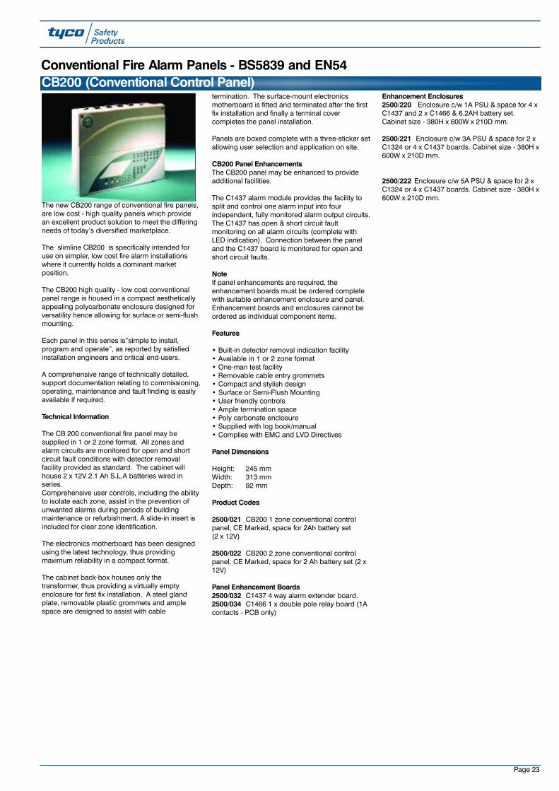
Page 23
The new CB200 range of conventional fire panels,are low cost - high quality panels which providean excellent product solution to meet the differingneeds of today’s diversified marketplace.
The slimline CB200 is specifically intended foruse on simpler, low cost fire alarm installationswhere it currently holds a dominant marketposition.
The CB200 high quality - low cost conventionalpanel range is housed in a compact aestheticallyappealing polycarbonate enclosure designed forversatility hence allowing for surface or semi-flushmounting.
Each panel in this series is”simple to install,program and operate”, as reported by satisfiedinstallation engineers and critical end-users.
A comprehensive range of technically detailed,support documentation relating to commissioning,operating, maintenance and fault finding is easilyavailable if required.
Technical Information
The CB 200 conventional fire panel may besupplied in 1 or 2 zone format. All zones andalarm circuits are monitored for open and shortcircuit fault conditions with detector removalfacility provided as standard. The cabinet willhouse 2 x 12V 2.1 Ah S.L.A batteries wired inseries.Comprehensive user controls, including the abilityto isolate each zone, assist in the prevention ofunwanted alarms during periods of buildingmaintenance or refurbishment. A slide-in insert isincluded for clear zone identification.
The electronics motherboard has been designedusing the latest technology, thus providingmaximum reliability in a compact format.
The cabinet back-box houses only thetransformer, thus providing a virtually emptyenclosure for first fix installation. A steel glandplate, removable plastic grommets and amplespace are designed to assist with cable
termination. The surface-mount electronicsmotherboard is fitted and terminated after the firstfix installation and finally a terminal covercompletes the panel installation.
Panels are boxed complete with a three-sticker setallowing user selection and application on site.
CB200 Panel EnhancementsThe CB200 panel may be enhanced to provideadditional facilities.
The C1437 alarm module provides the facility tosplit and control one alarm input into fourindependent, fully monitored alarm output circuits.The C1437 has open & short circuit faultmonitoring on all alarm circuits (complete withLED indication). Connection between the paneland the C1437 board is monitored for open andshort circuit faults.
NoteIf panel enhancements are required, theenhancement boards must be ordered completewith suitable enhancement enclosure and panel.Enhancement boards and enclosures cannot beordered as individual component items.
Features
• Built-in detector removal indication facility• Available in 1 or 2 zone format• One-man test facility• Removable cable entry grommets• Compact and stylish design• Surface or Semi-Flush Mounting• User friendly controls• Ample termination space• Poly carbonate enclosure• Supplied with log book/manual• Complies with EMC and LVD Directives
Panel Dimensions
Height: 245 mmWidth: 313 mmDepth: 92 mm
Product Codes
2500/021 CB200 1 zone conventional controlpanel, CE Marked, space for 2Ah battery set (2 x 12V)
2500/022 CB200 2 zone conventional controlpanel, CE Marked, space for 2 Ah battery set (2 x12V)
Panel Enhancement Boards2500/032 C1437 4 way alarm extender board.2500/034 C1466 1 x double pole relay board (1Acontacts - PCB only)
Enhancement Enclosures2500/220 Enclosure c/w 1A PSU & space for 4 xC1437 and 2 x C1466 & 6.2AH battery set.Cabinet size - 380H x 600W x 210D mm.
2500/221 Enclosure c/w 3A PSU & space for 2 xC1324 or 4 x C1437 boards. Cabinet size - 380H x600W x 210D mm.
2500/222 Enclosure c/w 5A PSU & space for 2 xC1324 or 4 x C1437 boards. Cabinet size - 380H x600W x 210D mm.
CB200 (Conventional Control Panel)Conventional Fire Alarm Panels - BS5839 and EN54
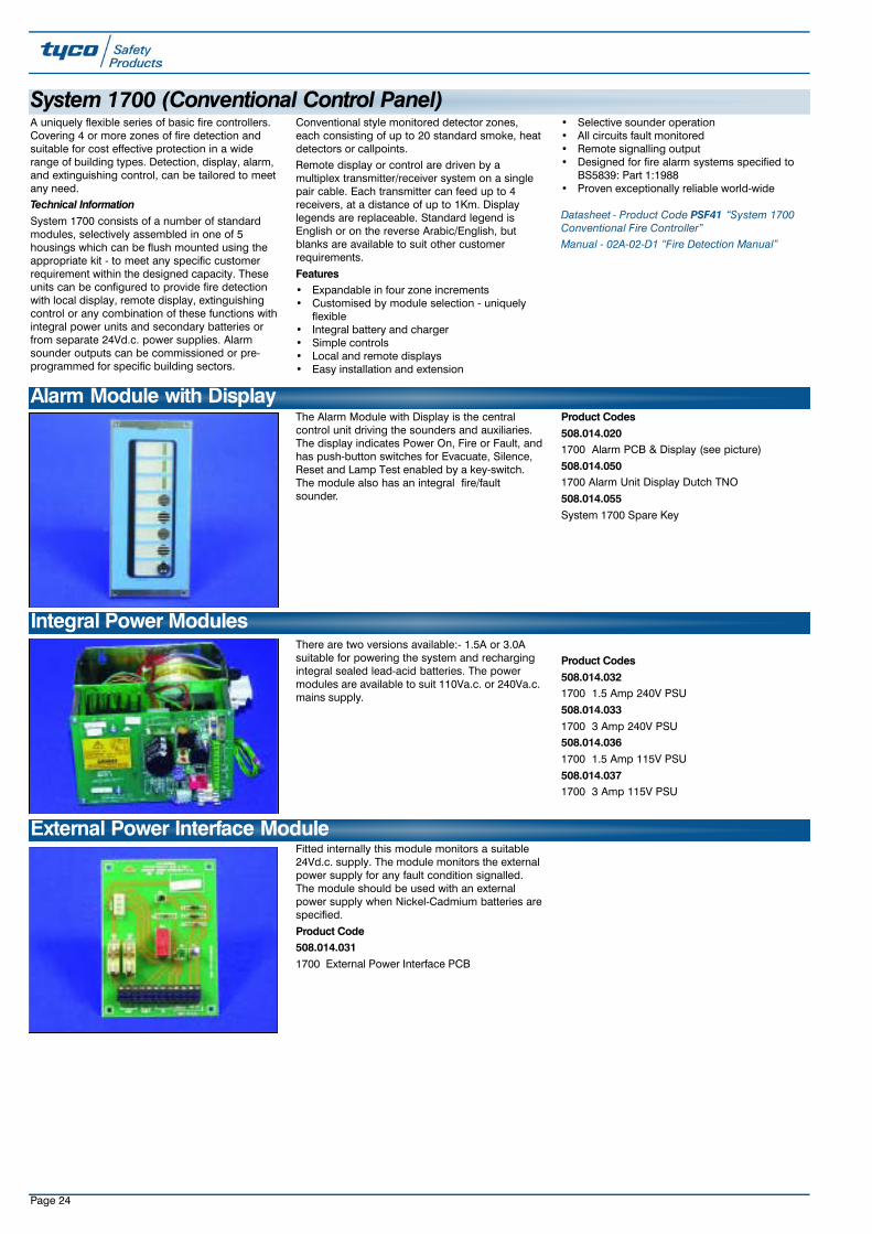
Page 24
Fitted internally this module monitors a suitable24Vd.c. supply. The module monitors the externalpower supply for any fault condition signalled.The module should be used with an externalpower supply when Nickel-Cadmium batteries arespecified.
Product Code508.014.0311700 External Power Interface PCB
There are two versions available:- 1.5A or 3.0Asuitable for powering the system and rechargingintegral sealed lead-acid batteries. The powermodules are available to suit 110Va.c. or 240Va.c.mains supply.
Product Codes508.014.0321700 1.5 Amp 240V PSU
508.014.0331700 3 Amp 240V PSU508.014.0361700 1.5 Amp 115V PSU
508.014.0371700 3 Amp 115V PSU
Integral Power Modules
External Power Interface Module
A uniquely flexible series of basic fire controllers.Covering 4 or more zones of fire detection andsuitable for cost effective protection in a widerange of building types. Detection, display, alarm,and extinguishing control, can be tailored to meetany need.Technical InformationSystem 1700 consists of a number of standardmodules, selectively assembled in one of 5housings which can be flush mounted using theappropriate kit - to meet any specific customerrequirement within the designed capacity. Theseunits can be configured to provide fire detectionwith local display, remote display, extinguishingcontrol or any combination of these functions withintegral power units and secondary batteries orfrom separate 24Vd.c. power supplies. Alarmsounder outputs can be commissioned or pre-programmed for specific building sectors.
Conventional style monitored detector zones,each consisting of up to 20 standard smoke, heatdetectors or callpoints. Remote display or control are driven by amultiplex transmitter/receiver system on a singlepair cable. Each transmitter can feed up to 4receivers, at a distance of up to 1Km. Displaylegends are replaceable. Standard legend isEnglish or on the reverse Arabic/English, butblanks are available to suit other customerrequirements.
Features• Expandable in four zone increments• Customised by module selection - uniquely
flexible• Integral battery and charger• Simple controls• Local and remote displays• Easy installation and extension
• Selective sounder operation• All circuits fault monitored• Remote signalling output• Designed for fire alarm systems specified to
BS5839: Part 1:1988• Proven exceptionally reliable world-wide
Datasheet - Product Code PSF41 “System 1700Conventional Fire Controller”Manual - 02A-02-D1 “Fire Detection Manual”
The Alarm Module with Display is the centralcontrol unit driving the sounders and auxiliaries.The display indicates Power On, Fire or Fault, andhas push-button switches for Evacuate, Silence,Reset and Lamp Test enabled by a key-switch.The module also has an integral fire/faultsounder.
Product Codes508.014.0201700 Alarm PCB & Display (see picture)
508.014.0501700 Alarm Unit Display Dutch TNO
508.014.055System 1700 Spare Key
Alarm Module with Display
System 1700 (Conventional Control Panel)

Page 25
Mounted internally this module has 4 heavy dutyrelays each with a single changeover contact(rated 5A @ 30Vd.c.). The relays are normallyenergised from the individual zone outputs of thezone module.
Product Code508.014.0281700 Relay PCB
This module allows up to 4 groups of sounders tobe activated in a pre-programmed response fromup to 10 zones of detection. Each group can beprogrammed to respond in either pulsing orcontinuous output. Each output is fused at [email protected].
Product Code508.014.0261700 Sector Sounder PCB
This module allows for extra power to be suppliedto a sounder circuit. It is normally used whenlarge numbers of sounders are required in onecircuit or where long distances create volt-dropproblems. Additional current is 1.5A.
Product Code508.014.0271700 Sounder Extension PCB
Relay Module
Sector Sounder Module
Sounder Booster Module
508.014.0231700 4 Zone PCB & Display
508.014.0241700 8 Zone PCB & Display
This module provides the power to eachdetection zone which respond to four conditions,open-circuit fault, quiescent, alarm or short-circuitfault. Individual indication is given for either Alarmor Fault. Each zone has a corresponding outputwhich is energised in an alarm condition and issuitable for driving zonal relays and/or auxiliarymodules i.e. multiplexed repeater.
Four or Eight Zone Module with Display

Page 26
This module transmits up to 16 independentsignals plus common alarm or fault to up to 4multiplex receiver modules at remote locationsover a pair of signal wires (max. length 1 Km).
Product Code508.014.0291700 Multiplex TX PCB
These modules display the information from theMultiplex receiver module. The Remote Alarmdisplay provides indication of Fire, Fault, andPower On together with Silence and Lamp Testfacilities. The Repeater Display module providesup to 16 Fire indications.Product Codes508.014.0211700 Alarm Repeater Display
508.014.0221700 16 Zone Repeater Display
This module receives and encodes the signalsfrom a multiplex transmitter module. The outputscan be used to drive either a Repeater displaymodule, Mimic indicators etc.Product Code508.014.0301700 Multiplex RX PCB
This module provides for complete control of agaseous extinguishing system. The inputcommands are taken from the coincident zonaloutputs. The module also has an independentManual Release facility and has indicators forManual-Automatic mode, Gas Released andDisabled conditions together with a key switch formode selection. The module has facilities forextensive electrical fault monitoring, cylinderpressure monitoring, and an adjustable time-delay before gas release.
Multiplex Transmitter Module
Multiplex Receiver Module
Repeater Display Module
Extinguishing Module and Display
Product Code508.014.0561700 Extinguishing Control PCB and Display
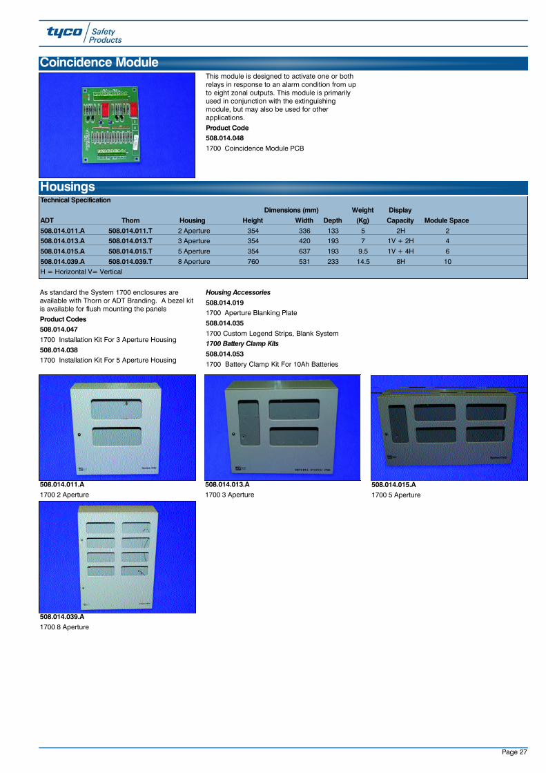
Page 27
As standard the System 1700 enclosures areavailable with Thorn or ADT Branding. A bezel kitis available for flush mounting the panels
Product Codes508.014.0471700 Installation Kit For 3 Aperture Housing
508.014.0381700 Installation Kit For 5 Aperture Housing
Housing Accessories508.014.0191700 Aperture Blanking Plate
508.014.0351700 Custom Legend Strips, Blank System 1700 Battery Clamp Kits508.014.0531700 Battery Clamp Kit For 10Ah Batteries
HousingsTechnical Specification
Dimensions (mm) Weight DisplayADT Thorn Housing Height Width Depth (Kg) Capacity Module Space508.014.011.A 508.014.011.T 2 Aperture 354 336 133 5 2H 2508.014.013.A 508.014.013.T 3 Aperture 354 420 193 7 1V + 2H 4
508.014.015.A 508.014.015.T 5 Aperture 354 637 193 9.5 1V + 4H 6
508.014.039.A 508.014.039.T 8 Aperture 760 531 233 14.5 8H 10H = Horizontal V= Vertical
508.014.011.A1700 2 Aperture
508.014.013.A1700 3 Aperture
This module is designed to activate one or bothrelays in response to an alarm condition from upto eight zonal outputs. This module is primarilyused in conjunction with the extinguishingmodule, but may also be used for otherapplications.
Product Code508.014.0481700 Coincidence Module PCB
Coincidence Module
508.014.015.A1700 5 Aperture
508.014.039.A1700 8 Aperture

Page 28
General Wiring Diagram
The range of NT100 panels are state-of-the-artintelligent fire panels, which provide many of thefeatures normally only found on more expensiveanalogue addressable panels. The range ofcontrol panels are LPCB approved to EN54Pt. 2and 4 and include many local approval authoritiesaround the world. The panels are supplied in 8and 16 zone versions. Each detection zone cansupport up to 32 conventional detectors. The userinterface is provided through a combination ofLEDs and a 2 x 40 character LCD display. TheLCD display provides a full customer definabletext display of the alarm or fault condition whilstalso displaying zones in alarm, fault or isolatestatus. The display also indicates the outputs thathave been activated. Each control panel can haveup to a maximum of 3 repeaters.Features• LPCB & ANPI (BOSEC) approved to EN54
Parts 2 and 4• Customer friendly, multi language information
on LCD display• Comprehensive fault diagnostics• 8 and 16 zone Panels• Can be used with a wide range of approved
detectors• Detector removal monitoring• 4 monitored Sounder outputs up to 4A• 4 monitored Relay outputs• 3 programmable auxiliary inputs• 3 levels of alarm discriminations per zone• One common fault relay• Internal batteries (up to 12Ah)• Programmable cause and effect• Programmable user access levels• Can interface to intrinsically safe System 601• Manned/ unmanned mode• Optional fireman's interface• Optional printer• Optional repeater units• Optional I/O expansion board • 16 digital outputs or 16 relay output optionsTechnical SpecificationDimensions 320H x 430W x150D mmWeight 6.3kg
Power Supply 198 -264Va.c.
Quiescent Current 50mA @ 24Vd.c.Alarm Current 1Amp @ 24Vd.c.
Operating Temp 0 to +40°COperating Humidity 0-90% RH non-condensing
Datasheet - Product Code PSF95 “NT Fire ControlPanels”
NT100 Conventional Controllers
Product CodesThe following product codes include all theoptional extras which can be included as part ofyour customer's requirements. Additional spareparts are also included.
509.022.001NT100 Series Spare Commissioning Kit
Included With All Panels
509.022.008PRN-02 Spare Printer Paper For PRN-01(Supplied one per pack)
509.022.011NT100 Spare PSU For NT,NTR & NTF Variants
509.022.013NT Flush Mount Bezel
Ancillaries509.022.035NT/NTR/NTF CPU Board V1.9 Spare
509.022.033NT/NTR/NTF Display PCB square
Standard Fire Control Panel Standard Fire Repeater PanelCountry NT108 NT116 NT116RU.K. 508.022.008 508.022.016 508.022.038Spain - 508.022.019 -Belgium 508.022.009 508.022.017 508.022.044Holland 508.022.010 508.022.018 -
Fire Panels with Integral Fireman’s InterfaceCountry NTF08 NTF16Finland 508.022.011 508.022.029Denmark 508.022.014 -Holland 508.022.042 508.022.043
Up to 3 repeaters

Page 29
The range of NTR gas release panels are state-of-the-art intelligent panels, which enable a widevariety of gas release applications to beimplemented. The panel is provided with defaultsettings to suit most INERGEN®, FM200™ andCO2 applications and can be programmed to suitmost other gas releasing applications. Forcompatibility with latest standards the panelcomplies with all relevant parts of EN54 part 2and 4. The NTR panel is designed to comply withBS7273 and can be installed to fully comply withBS5839 Pt 1 and BS6266.System Operation (Default UK Operation)
Stage 1 - The panel stays in Stage1 Fire Alarmuntil the fire or false alarm source is removed andthe panel is reset or Stage 2 ensues.
Stage 2 - The panel stays in Stage 2 for 30seconds (adjustable) to provide a Pre-releaseWarning during which time the HOLD or ABORTsequences can be initiated.Stage 3 - The panel remains in Stage 3 GasRelease for the solenoid firing time or until therelease confirmation is received from the HighPressure Switch.
Stage 4 - The panel remains in the Fire Alarmcondition and indicates the gas releasedmessage until the system is silenced and reset.Failure to receive a release confirmation willinitiate a fault.
The user interface is provided through acombination of LEDs and a 2 x 40 character LCD
display. The LCD display provides a full customerdefinable text display of the alarm or faultcondition whilst also displaying zones in alarm,fault or isolate status. The display also indicatesthe outputs that have been activated.
Features• ANPI (BOSEC) Approved• Customer friendly, multi language information
on LCD display• Comprehensive fault diagnostics• Manual release zone - direct to stage 2• Can be used with a wide range of approved
detectors• Detector removal monitoring• 2 monitored Sounder outputs up to 4A• 2 monitored Solenoid circuits• 4 monitored Relay outputs• 3 programmable auxiliary inputs• 3 levels of alarm discriminations per zone• One common fault relay• Internal batteries (up to 12Ah)• Programmable cause and effect• Programmable user access levels• Can interface to intrinsically safe System 601• High and Low pressure monitoring• Initial/Reserve changeover facility• Optional Door Interlock• Optional remote hold and abort• Optional Auto/Manual key switches • Optional I/O expansion board
• 16 digital outputs or 16 relay output optionsTechnical SpecificationDimensions 320H x 430W x 150D mm
Weight 6.3kgPower Supply 198 -264Va.c.
Quiescent Current 50mA @ 24Vd.c.
Alarm Current 1Amp @ 24Vd.c.Operating Temp 0 to +40°C
Operating Humidity 0-90% RH non-condensing
Note: The NTR is compatible with the T500 rangeof ancillaries.
Datasheet - Product Code PSF106 “NTR IntelligentRelease Panels”
NTR100 Conventional Extinguishing Controllers
Product CodesThe following product codes include all theoptional extras which can be included as part ofyour customer's requirements. Additional spareparts are also included.
509.022.001NT100 Series Spare Commissioning Kit IncludedWith All Panels
509.022.007PRN-01 Optional Integral Printer For Use With AllNT Controller Variants 509.022.008PRN-02 Spare Printer Paper For PRN-01 suppliedone per pack.
509.022.011NT100 Spare PSU For NT,NTR & NTF Variants
509.022.013NT Flush Mount Bezel
509.022.033NT/NTR/NTF Display PCB Spare
Product CodesNTR-08 NTR-16
Single Area Dual AreaUK 508.022.003 -Belgian 508.022.004 -Dutch - 508.022.021Danish 508.022.006 508.022.025Finnish 508.022.001 508.022.022Norwegian - 508.022.023Swedish 508.022.002 -
509.022.007PRN-01 Optional Integral Printer for use with NT &NTF Controller Variants
509.022.003NTX-01 4 Way Expansion Board - Supplied Fittedto the NTF And NTR Controllers. Also SupportsNTX-02,03,04 Expansion Boards
509.022.004NTX-02 16 Way Relay Output Board(24Vd.c.@1A) Requires NTX-01 Expansion Board
509.022.005NTX-03 16 Way Digital Output Driver Board -Requires NTX-01 Expansion Board
509.022.006NTX-04 16 Way Digital Input Board for use onSpecial NT Controller Variants only

Page 30
NTR - Typical Wiring Schematic for Single Area P anels
Extinguishant Schematic Configuration with Extinguishant Solenoid Extinguishant Schematic Configuration with Pilot Container Solenoid
Extinguishant Initial/Reserve Schematic with Extinguishant SolenoidExtinguishant Initial/Reserve Schematic with Pilot Container Solenoid
Typical Extinguishing Gas Release Applications
PRESSURESWITCHES

Page 31
IntroductionThe self-contained MXCE panels provide all therequired monitoring and control functions toinstall a complete fire detection, alarm andextinguishing system. The MXCE T540 and T550controllers support 2 and 4 detection zonesrespectively. Coincidence operation is availableas standard on zones 1 and 2. Additionally onthe T550, zones 3 and 4 can be used forextinguishing (coincidence) or as independent firealarm zones.
The exceptionally priced T540 and T550controllers are designed as feature enhanced,aesthetically modern replacement for the current,more expensive and heavily dated T530 and T520Extinguishing panels. Additionally, theintroduction of 2-wire sounder capability(detectors and sounders on the same 2-wirecircuit) to the extinguishing systems market willachieve significant cost and installation savings.
Installation FeaturesThe MXCE offers flexible mounting arrangements,with easily removable door, multiple conduitentries and large terminations, designedspecifically for simplified installation.• Reversible back-box for top or bottom conduit
and cable entry• Surface or semi-flush mount
• Terminations that suit up to 2.5mm2 CSA cablePower SupplyThe power supply is designed to comply with thelatest standard (EN54 pt4). The internal mainsPSU provides all power plus charging andmonitoring of the 2 x 12V lead acid batteries (upto 7 Ah).
• 1.8A PSU/Charger• Panel battery capacity - 2 x 7Ah batteries
internally
Panel Functions• Coincidence operation zones 1 and 2• Optional coincidence operation on zones 3
and 4(T550)• Auto/Manual select• 2-wire sounders (on the detection zones)
Inputs and Outputs• 2 or 4 zones• First stage sounders (sounder circuit 1 and 2-
wire sounders)• Second stage sounders (sounder circuit 2)• Mode-select Auto/Manual input• Extinguishing Disable input• Hold button input• Abort button input• High and low pressure extinguishant monitor
inputs• Manual electrical release input• Signalling fault monitor
The following additional Inputs/Outputs areavailable on the T550• Fire and fault relays• Mode select/status indication• Mimic inputs (silence/reset/evacuate)• Door interlocks
MXC-DIGIA uniquely designed plug-in digital dialler whichfits inside the panel and provides fire, fire test and fault signalling.
SoundersEach MXCE zone can support up to sixteen Tyco
2-wire sounders, which can be any combination of Tyco 602SBD sounder base units or wall mounted Symphoni Sounders.
Panel Features• Available in 2 and 4 zone variants• Operates with Tyco 600 Series Conventional
Detectors• All zones supports Tyco 2-wire sounders• 4 zones variant offers extinguishing coinci-
dence functionality on zones 3 & 4• T550 supports up to 3 x T56x Series of remote
Status Indicators• Uniquely supports plug-in Central Station com-
municator within the panel unit• Designed to comply with BS7273 and EN54
pts 2 &4 • Can be installed to meet the requirements of
BS5839 pt1• MXCE LED display replaces T530 filaments -
reduces associated maintenance and timecosts
• Aesthetically pleasing design - 332W x 240H x100D (mm).
Product Codes508.030.501MXCE T540 2 zone conventional extinguishingcontroller508.030.502MXCE T550 4 zone conventional extinguishingcontroller509.030.005MXC-DIGI Plug-in Scantronic MinicomCommunicator and mounting kit.
509.030.016MXCE Zone End of Line Unit (Pk 8)
509.030.015MXCE Spare Key (2 off)
MXCE Conventional Fire Detection & Extinguishing Controller

Page 32
The prescient range of extinguishant panels is apowerful yet user-friendly series of control panels.They are designed and manufactured to a highstandard and provide unrivaled value for moneyby offering a highly featured panel at a lowermarket price.
Each panel in this series has extensiveconfiguration options but remains “simple toinstall, program and operate” as reported bysatisfied installation engineers and critical end-users.
A comprehensive range of technically detailed,support documentation relating to commission-ing, operating, maintenance and fault finding iseasily available if required. In addition, acomplete range of compatible accessories isavailable to support the series and satisfy mostcustomer requirements.
The prescient range of extinguishing panels isavailable in two variants - either as a gaseousextinguishant panel or a pre-action water sprinklerpanel. Panels are housed in well-designedenclosures with partially glazed doors.Steel parts are finished in a hard-wearing epoxypaint.
Three fully - monitored detection zones areprovided. Zones 1 and 2 normally provide firststage and second stage fire conditions to allowextinguishant discharge (double-knock zones).Zone 3 is an auxiliary zone for detection onlypurposes. Zone 4 is used as a manual releasezone.Two fully monitored alarm circuits are provided,each rated at 1A and may have variousconfiguration options via the engineers’ DIL
switch settings. Two fully monitoredactuator/solenoid circuits, each rated at 1A,operate simultaneously upon “extinguishantrelease”.
The panel can be operated in either automaticmode or manual mode. In the manual mode, thedetection circuits will continue to operate, givingfirst stage alarms and signals to ancillaryequipment, but will not automatically actuate theextinguishing systems. This mode can only beoverridden by the operation of a manual releaseunit. On operation of the manual release, aseparate or different sounder could be activated.In the automatic mode, following a double knocksituation, the release facility will be activated atthe end of the time period.
The panel provides 0.5 A output at 28V DC tooperate interior/ exterior status indicator units.Outputs for auto, manual and discharge areprovided at 250mA each.
Eight normally - open inputs provide for remoteevacuate, silence alarms, systems reset, lock-offinput, low pressure input, gas dischargedpressure switch input, remote abort and remotefault. Clean contact relays are provided for firststage signalling, second stage signalling, systemreset, common fire, common fault and systemdischarged.
Please note that in contrast to the T530, the standalone “abort” button feature is not compatiblewith this panel.
Top-entry plastic grommets, bottom-rear entryplastic grommets (for mains) and rear entryknock-outs are designed to assist with cabletermination.
Panels are boxed complete with three-sticker setsallowing user selection and application on site.
Features• Suitable for gaseous extinguishing & pre-action
water sprinkling systems• Designed to BS7273 Part 1• Monitored actuator/solenoid release• Comprehensive relay signalling facilities • Easily removable chassis• Removable cable-entry grommets• Adjustable pre-discharge delay• Variable discharge configuration• Membrane facia with tactile switches• Zone isolate features• Complies with EMC and LVD Directives
Panel DimensionsHeight: 445mm
Width: 405mm
Depth: 105mm
Product CodesPrescient Gaseous Extinguishing Panel 2500/046 Prescient gaseous extinguishing panel- 2 extinguishing zones, programmablecoincidence, 1 manual release zone, 1 peripheralzone; space for 6.2 Ah battery set (2 x 12V).
Prescient Pre-Action Water SprinklerExtinguishing Panel2500/045 Prescient pre-action water sprinklerextinguishing panel - 2 extinguishing zones,programmable coincidence, 1 manual releasezone, 1 peripheral zone; space for 6.2Ah batteryset (2 x 12v)
Extinguishing System Extras2500/048 Status indicator; maximum load - 3 perpanel.
2500/049 Status indicator complete with manualrelease and auto/manual keyswitch; maximumload - 3 per panel.
2500/050 Status indicator complete with manualrelease, auto/manual keyswitch and timer hold;maximum load - 3 per panel.2500/051 Weatherproof 3 way status indicator;maximum load - 1 per panel.
2500/052 Weatherproof 3 way status indicatorwith key switch; maximum load - 1 per panel.
2501/025 Manual release unit.2501/028 Weatherproof manual release unit (IP65).
2500/507 Weight monitor system complete (1load cell and 1 control unit).2500/053 Actuator suppression kit.
Prescient (Conventional Extinguishing Controllers)

Page 33
The T510 is a manual keyswitch operated unit foruse on extinguishing systems. The unit allowsmanual changeover between MAIN andRESERVE cylinder banks and includes an OFFposition that disables the operation of thesolenoids. The T510 also provides a fault relay,which monitors the solenoid and solenoid wiring.The T510 is provided with 2 keys.Technical SpecificationInput power supply: 24Vd.c. nominal
Current consumption:Standby - 50mAFault - 15mARelease - 65mA (excluding solenoid)
Fault relay: Changeover contact 1A @ 30V d.c.
Solenoids: Switched positive for 24V
Dimensions: 196 H x 196 W x 90 D mmWeight: 2 Kg
Operating Temp: -10 to +55oCHumidity: up to 95% RH non-
condensing
EMC/RFI: CE marked
Product Code526.001.016.TT510 Extinguishing - Main To ReserveChangeover Unit - Thorn branded
Datasheet - Product Code PSF30 “T530 FireDetection & Extinguishing Systems Control Unit”Manual - 18A-04-D1 “Fire Detection Manual”
T510 Extinguishant Changeover Unit
A four way status indicator and mode selectkeyswitch for use with extinguishing controllers. Inaddition to the indications provided on the T563,the T564 has a mode select keyswitch and LEDindicator to identify which units initiated themanual mode.
The T564 provides the following features:- • Clear Visual Indications• Modern design to compliment all Interiors• L E D Visual Indicators• Removable mode select key to provide
functional security• Compatible with standard UK double gang
electrical back boxes
Technical SpecificationInput Power Supply: 24Vdc nominalCurrent Consumption: 30mA per LEDDimensions: 86W x 146Hmm
Product Code 5 0 8 . 0 3 0 . 5 0 4M XCE T564 Indicator Status Unit with ModeSelect Switch
T564 Extinguishing System Status Indicator and Mode Select Switch
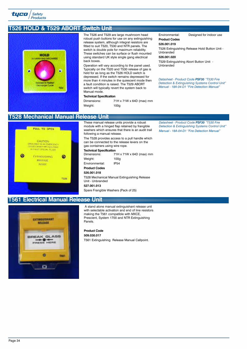
Page 34
These manual release units provide a robustmodule with a hinged flap retained by frangiblewashers which ensures that there is an audit trailfollowing a manual release.
The T528 provides access to a pull handle whichcan be connected to the release levers on thegas containers using wire rope.
Technical SpecificationDimensions: 71H x 71W x 64D (max) mmWeight: 100g
Environmental: IP54
Product Codes526.001.018T528 Mechanical Manual Extinguishing ReleaseUnit - Unbranded
527.001.013Spare Frangible Washers (Pack of 25)
Datasheet - Product Code PSF30 “T530 FireDetection & Extinguishing Systems Control Unit”Manual - 18A-04-D1 “Fire Detection Manual”
T528 Mechanical Manual Release Unit
The T526 and T529 are large mushroom headrobust push buttons for use on any extinguishingrelease system, although integral resistors arefitted to suit T520, T530 and NTR panels. Theswitch is double pole for maximum reliability.These switches can be surface or flush mountedusing standard UK style single gang electricalback boxes. Operation will vary according to the panel used.Typically on the T520 and T530 release of gas isheld for as long as the T526 HOLD switch isdepressed. If the switch remains depressed formore than 4 minutes in the quiescent mode thena fault condition is raised. The T529 ABORTswitch will typically revert the system back toManual mode.
Technical SpecificationDimensions: 71H x 71W x 64D (max) mm
Weight: 100g
Environmental: Designed for indoor useProduct Codes526.001.019T526 Extinguishing Release Hold Button Unit -Unbranded
526.001.020T529 Extinguishing Abort Button Unit -Unbranded
Datasheet - Product Code PSF30 “T530 FireDetection & Extinguishing Systems Control Unit”Manual - 18A-04-D1 “Fire Detection Manual”
T526 HOLD & T529 ABORT Switch Unit
A stand alone manual extinguishant release unitwith selectable activation and end of line resistorsmaking the T561 compatible with MXCE,Prescient, System 1700 and NTR ExtinguishingPanels.
Product Code509.030.017T561 Extinguishing Release Manual Callpoint.
T561 Electrical Manual Release Unit

Page 35
Extinguishing Door Interlock Ancillaries & T500 Series SparesA microswitch lock keep can be used with adeadlock to provide a signal to the T525 modeselect unit or direct to the panel to ensure that theextinguishing system is only put into Automaticmode when the door is locked shut.
Datasheet - Product Code PSF30 “T530 FireDetection & Extinguishing Systems Control Unit” Manual - 18A-04-D1 “Fire Detection Manual”
Product Codes527.001.028Micro-switch Lock Keep & Back-plate ForDeadlock
527.001.003Top Hat Frangible Insert (Spare)527.001.013Frangible Washers (Spare)
599.001.011Lamp 28V 40mA Midget Used On T505/515
599.001.012Lamp 28V 60mA Used On T525
599.001.020Lamp 36V 30mA Bi-Pin Used On T520 & T530
Technical SpecificationDimensions:
H(mm) W(mm) D(mm)E1 100 100 115
E3 300 100 115
I3 230 75 75I4 230 75 75
Weatherproof Extinguishing Indicator Units
540.007.002E3 Red/Amber/Green lamp unit
Heavy Duty IP67 Cast Aluminium Surface MountLamp Unit Three 24Vd.c. lamps: Red labelled 'Extinguishing System Operated'
Amber labelled ' Extinguishing System AutomaticControl'
Green labelled 'Extinguishing System ManualControl'
540.007.001E1 Single Red lamp unitHeavy Duty IP67 Cast Aluminium Surface MountLamp Unit. Single 24V d.c. red lamp labelled'Extinguishing System Operated' 540.007.006
I3 Red/Amber/Green lamp unit
Sealed IP67 ABS Surface Mount Lamp UnitThree 24V d.c. lamps:
Red labelled 'Gas Released'
Amber labelled 'Auto'Green labelled 'Manual'
540.007.007I4 lamp unit as I3 including auto/manualkeyswitch
T563 Extinguishing System Status IndicatorA three way status Indicator for use withextinguishing controllers which providesindication of automatic/manual mode and gasreleased.
The T563 provides the following features:-
•Clear Visual Indications•Modern Design to compliment all Interiors•LED Visual Indicators•Compatible with standard UK single gang
electrical back boxes
Technical SpecificationInput Power Supply: 24 Vdc nominal
Current Consumption: 30mA per LED
Dimensions: 86 x 86mm
Product Code508.030.503MXCE T563 Indicator Status Unit
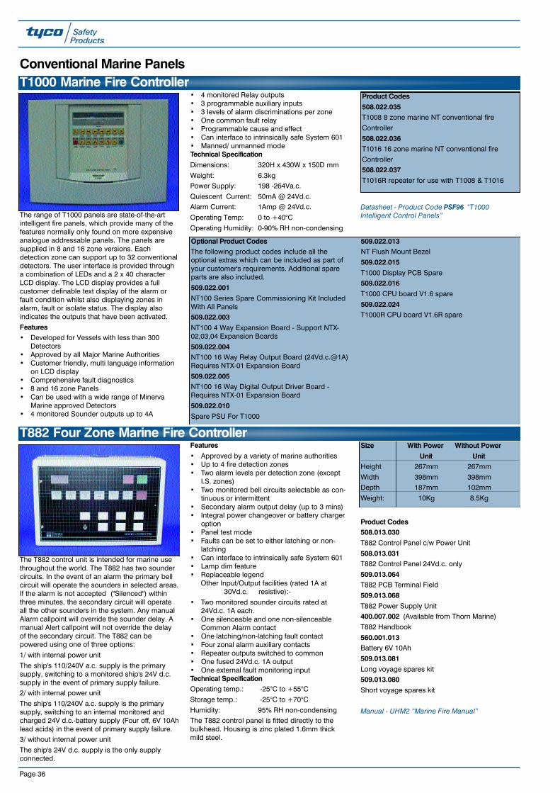
Page 36
The range of T1000 panels are state-of-the-artintelligent fire panels, which provide many of thefeatures normally only found on more expensiveanalogue addressable panels. The panels aresupplied in 8 and 16 zone versions. Eachdetection zone can support up to 32 conventionaldetectors. The user interface is provided througha combination of LEDs and a 2 x 40 characterLCD display. The LCD display provides a fullcustomer definable text display of the alarm orfault condition whilst also displaying zones inalarm, fault or isolate status. The display alsoindicates the outputs that have been activated.
Features• Developed for Vessels with less than 300
Detectors• Approved by all Major Marine Authorities• Customer friendly, multi language information
on LCD display• Comprehensive fault diagnostics• 8 and 16 zone Panels• Can be used with a wide range of Minerva
Marine approved Detectors• 4 monitored Sounder outputs up to 4A
• 4 monitored Relay outputs• 3 programmable auxiliary inputs• 3 levels of alarm discriminations per zone• One common fault relay• Programmable cause and effect• Can interface to intrinsically safe System 601• Manned/ unmanned modeTechnical SpecificationDimensions: 320H x 430W x 150D mm
Weight: 6.3kgPower Supply: 198 -264Va.c.
Quiescent Current: 50mA @ 24Vd.c.Alarm Current: 1Amp @ 24Vd.c.
Operating Temp: 0 to +40°C
Operating Humidity: 0-90% RH non-condensing
Datasheet - Product Code PSF96 “T1000Intelligent Control Panels”
Optional Product CodesThe following product codes include all theoptional extras which can be included as part ofyour customer's requirements. Additional spareparts are also included.
509.022.001NT100 Series Spare Commissioning Kit IncludedWith All Panels509.022.003NT100 4 Way Expansion Board - Support NTX-02,03,04 Expansion Boards
509.022.004NT100 16 Way Relay Output Board (24Vd.c.@1A)Requires NTX-01 Expansion Board
509.022.005NT100 16 Way Digital Output Driver Board -Requires NTX-01 Expansion Board
509.022.010Spare PSU For T1000
509.022.013NT Flush Mount Bezel
509.022.015T1000 Display PCB Spare 509.022.016T1000 CPU board V1.6 spare
509.022.024T1000R CPU board V1.6R spare
Product Codes508.022.035T1008 8 zone marine NT conventional fire
Controller
508.022.036T1016 16 zone marine NT conventional fire
Controller508.022.037T1016R repeater for use with T1008 & T1016
T1000 Marine Fire ControllerConventional Marine Panels
The T882 control unit is intended for marine usethroughout the world. The T882 has two soundercircuits. In the event of an alarm the primary bellcircuit will operate the sounders in selected areas.If the alarm is not accepted ("Silenced") withinthree minutes, the secondary circuit will operateall the other sounders in the system. Any manualAlarm callpoint will override the sounder delay. Amanual Alert callpoint will not override the delayof the secondary circuit. The T882 can bepowered using one of three options:
1/ with internal power unit
The ship's 110/240V a.c. supply is the primarysupply, switching to a monitored ship's 24V d.c.supply in the event of primary supply failure.2/ with internal power unit
The ship's 110/240V a.c. supply is the primarys u p p l y, switching to an internal monitored andcharged 24V d.c.-battery supply (Four off, 6V 10Ahlead acids) in the event of primary supply failure.3/ without internal power unit
The ship's 24V d.c. supply is the only supplyconnected.
Features• Approved by a variety of marine authorities• Up to 4 fire detection zones • Two alarm levels per detection zone (except
I.S. zones)• Two monitored bell circuits selectable as con-
tinuous or intermittent• Secondary alarm output delay (up to 3 mins)• Integral power changeover or battery charger
option• Panel test mode• Faults can be set to either latching or non-
latching• Can interface to intrinsically safe System 601• Lamp dim feature• Replaceable legend
Other Input/Output facilities (rated 1A at30Vd.c. resistive):-
• Two monitored sounder circuits rated at24Vd.c. 1A each.
• One silenceable and one non-silenceableCommon Alarm contact
• One latching/non-latching fault contact • Four zonal alarm auxiliary contacts• Repeater outputs switched to common• One fused 24Vd.c. 1A output • One external fault monitoring inputTechnical SpecificationOperating temp.: -25°C to +55°C
Storage temp.: -25°C to +70°C
Humidity: 95% RH non-condensingThe T882 control panel is fitted directly to thebulkhead. Housing is zinc plated 1.6mm thickmild steel.
Product Codes508.013.030T882 Control Panel c/w Power Unit
508.013.031T882 Control Panel 24Vd.c. only
509.013.064T882 PCB Terminal Field
509.013.068T882 Power Supply Unit400.007.002 (Available from Thorn Marine)
T882 Handbook
560.001.013Battery 6V 10Ah
509.013.081Long voyage spares kit509.013.080Short voyage spares kit
Manual - UHM2 “Marine Fire Manual”
T882 Four Zone Marine Fire ControllerSize With Power Without Power
Unit UnitHeight 267mm 267mm
Width 398mm 398mmDepth 187mm 102mm
Weight: 10Kg 8.5Kg
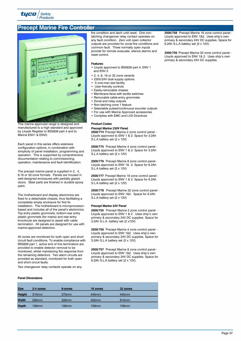
This marine approved range is designed andmanufactured to a high standard and approvedby Lloyds Register to BS5839 part 4 and toMarine ENV1 & ENV2.
Each panel in this series offers extensiveconfiguration options, in combination withsimplicity of panel installation, programming andoperation. This is supported by comprehensivedocumentation relating to commissioning,operation, maintenance and fault identification.
The precept marine panel is supplied in 2, 4,8,16 or 32-zone formats. Panels are housed inwell-designed enclosures with partially glazeddoors. Steel parts are finished in durable epoxypaint.
The motherboard and display electronics arefixed to a detachable chassis, thus facilitating acompletely empty enclosure for first fixinstallation. The motherboard is microprocessor-based and includes all of the panel’s electronics.Top-entry plastic grommets, bottom-rear entryplastic grommets (for mains) and rear-entryknockouts are designed to assist with cabletermination. All panels are designed for use withmarine-approved detectors.
All zones are monitored for both open and shortcircuit fault conditions. To enable compliance withBS5839 part 1, active end of line terminators areprovided to enable detector removal to bemonitored, whilst maintaining fire response fromthe remaining detectors. Two alarm circuits areprovided as standard, monitored for both openand short circuit faults.
Two changeover relay contacts operate on any
fire condition and latch until reset. One non-latching changeover relay contact operates onany fault condition. Zero volt open collectoroutputs are provided for zonal fire conditions andcommon fault. Three normally open inputsprovide for remote evacuate, silence alarms andreset control.
Features• Lloyds approved to BS5839 part 4, ENV 1. and ENV 2
• 2, 4, 8, 16 or 32 zone variants • 230V/24V dual supply options• A one-man test facility• User-friendly controls• Easily-removable chassis• Membrane facia with tactile switches• Removable cable-entry grommets• Zonal and relay outputs• Non-latching zone 1 feature• Selectable pulsed/continuous sounder outputs• For use with Marine Approved accessories• Complies with EMC and LVD Directives
Product CodesPrecept Marine 230V Panel2500/774 Precept Marine 2 zone control panel -Lloyds approved to ENV 1 & 2. Space for 3.2AhS.L.A battery set (2 x 12V)
2500/775 Precept Marine 4 zone control panel -Lloyds approved to ENV 1 & 2. Space for 3.2AhS.L.A battery set (2 x 12V)
2500/776 Precept Marine 8 zone control panel -Lloyds approved to ENV 1& 2. Space for 6.2AhS.L.A battery set (2 x 12V)
2500/777 Precept Marine 16 zone control panel -Lloyds approved to ENV 1 & 2. Space for 6.2AhS.L.A battery set (2 x 12V)
2500/778 Precept Marine 32 zone control panel -Lloyds approved to ENV 1&2. Space for 6.2AhS.L.A battery set (2 x 12V)
Precept Marine 24V Panel 2500/755 Precept Marine 2 zone control panel -Lloyds approved to ENV 1 & 2 . Uses ship’s ownprimary & secondary 24V DC supplies. Space for3.2Ah S.L.A. battery set (2 x12V)
2500/756 Precept Marine 4 zone control panel -Lloyds approved to ENV 1&2. Uses ship’s ownprimary & secondary 24V DC supplies. Space for3.2Ah S.L.A battery set (2 x 12V).
2500/757 Precept Marine 8 zone control panel -Lloyds approved to ENV 1&2. Uses ship’s ownprimary & secondary 24V DC supplies. Space for6.2Ah S.L.A battery set (2 x 12V).
2500/758 Precept Marine 16 zone control panel -Lloyds approved to ENV 1&2. Uses ship’s ownprimary & secondary 24V DC supplies. Space for6.2Ah S.L.A battery set (2 x 12V).
2500/759 Precept Marine 32 zone control panel -Lloyds approved to ENV 1& 2. Uses ship’s ownprimary & secondary 24V DC supplies.
Page 37
Precept Marine Fire Controller
Size 2-4 zones 8-zones 16 zones 32 zones
Height 310mm 370mm 445mm 445mm
Width 290mm 326mm 405mm 810mm
Depth 106mm 106mm 109mm 109mm
Panel Dimensions

Page 38
The T680 power changeover unit derives powerfor the T880 and T881 control panels. The unittakes primary power from the ship's AC supplyand provides a standby supply from the ship's24Vd.c. system i.e. the unit does not charge anyinternal batteries. The T680 unit provides asmooth changeover from primary to secondarysupply and vice-versa. It signals main andstandby supply failure signals to the T88x controlequipment. It also incorporates a dimming circuitfor the lamps of the controller.The interface to the control panel is made with asix core connection. The unit is approved by avariety of marine authorities
Technical SpecificationOperating temp.: -25°C to +70°C
Storage temp.: -25°C to +70°CHumidity: 95% RH non-condensing
Mains Supply: 120/240Va.c. ± 20%
at 50/60Hz Standby Supply: 24Vd.c. (must not exceed
32Vd.c.)
The T680 unit is normally mounted onto abulkhead using the H frame bracket. A bezel for19" rack mounting is available. The housing hastwo removable gland plates (top and bottom) forcable access.
Housing is zinc plated 1.6mm thick mild steel toBS 1706 ZN3.Finish is zinc plated and painted to P.S.121.121.022.
Dimensions: 267H x 398W x 150D mmIngress Protection: IP53
Weight: 17Kg (with bracket)13.5Kg (without bracket)
Product Codes508.013.016T680 Power changeover unit
509.013.026T680 Spares kit
Manual - UHM3 “Marine Fire Manual”
T680 Marine Power Change Over Unit

Page 39
Product Codes660.001.003Battery sealed L-A
560.001.013Battery sealed L-A replaces parts 3145 and 30-1023085Battery sealed L-A replaces 660.001.014 and
30-1113010Battery sealed L-A replaces 660.001.007, SLA21and 30-103
3071Battery sealed L-A replaces 660.001.009 and 30-105660.002.010Battery sealed L-A replaces 3146, SLA04 and 30-112
3072Battery sealed L-A replaces 660.001.005, SLA07and 30-101
660.002.012Battery sealed L-A replaces 3147, SLA012 and 30-110
560.001.016Battery sealed L-A replaces 3148, SLA17 and 30-109660.001.004Battery sealed L-A (Bolt terminal) replaces 3014,SLA24 and 30-106
560.001.012Battery sealed L-A replaces 3149, SLA38 and 30-107
3150Battery sealed L-A replaces SLA65 and 30-108
Batteries
518.003.00377CR19 Cable release 24Vd.c.
518.003.00477CR19 Cable release 240Va.c.
Cable Release & Release Button
Batteries, PSU and Door Release Units
519.001.007Door release button UK single gang mounting
Product Codes Model No. Voltage (V) Ah Dimensions (mm)Length Width Height
660.001.003 NP1.2-6 6 1.2 97 25 54.5
560.001.013 NP10-6 6 10 151 50 97.53085 NP1.2-12 12 1.2 97 48 54.5
3010 NP2.1-12 12 2.1 178 34 64
3071 NP2.8-12 12 2.8 151 50 97.5660.002.010 NP4-12 12 4 90 70 106
3072 NP7-12 12 7 151 65 97.5660.002.012 NP12-12 12 12 151 98 97
560.001.016 NP17-12 12 17 76 180 165
660.001.004 NP24-12B 12 24 175 166 125560.001.012 NP38-12 12 38 179 165 170
3150 NP65-12 12 65 350 166 174
Door Release Magnet
518.004.004Door Release Magnet Set 240Va.c.
518.004.005Door Release Magnet Set 24Vd.c.
High quality door release magnet sets completewith keeper plate.
Technical SpecificationPower Supply: 24Vd.c. 240Va.c.
Dimensions: 100H x 100W x 64D mm
Weight: 0.51Kg
Holding Force: 18Kg
IP Rating: IP40
Temp.: -10oC to +55oC
Current: 60mA 25mA
The 77CR19 cable release unit is used forautomatically closing roller shutter doors in theevent of a fire.
Technical Specification
Dimensions: 130H x 180W x 60D mm
Weight: 2.5Kg
Voltage: 240Va.c. / 24Vd.c.
Current: Negligible / 500mA
Temp.: -20oC to +45oC
Holding Force: 50Kg
IP Rating: IP40
Door Release Equipment
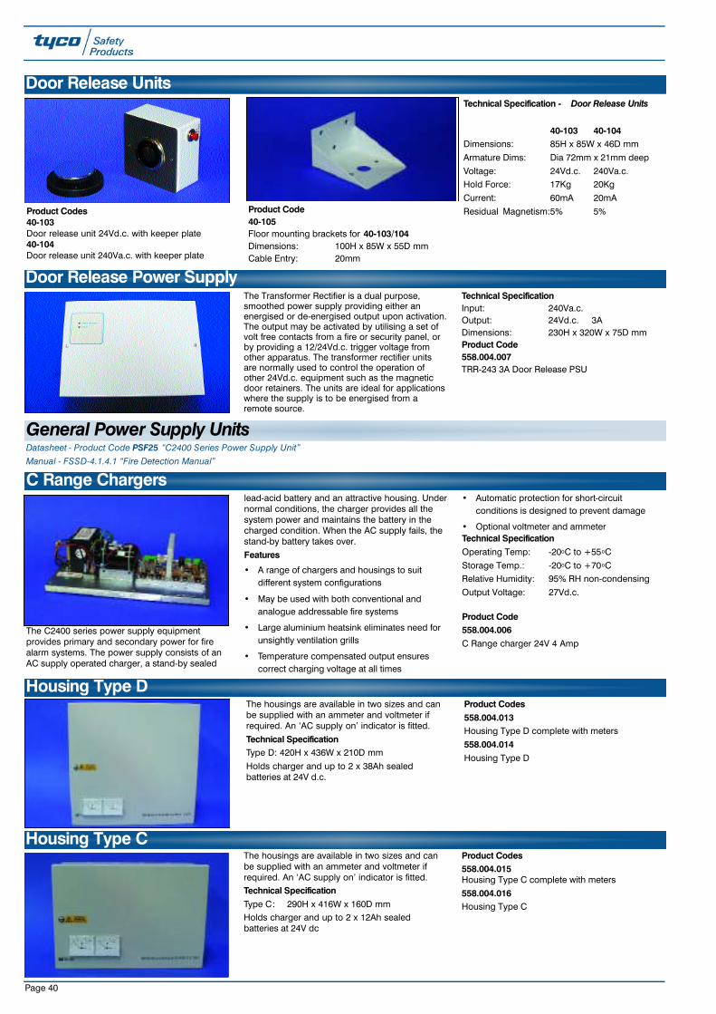
Page 40
The Transformer Rectifier is a dual purpose,smoothed power supply providing either anenergised or de-energised output upon activation.The output may be activated by utilising a set ofvolt free contacts from a fire or security panel, orby providing a 12/24Vd.c. trigger voltage fromother apparatus. The transformer rectifier unitsare normally used to control the operation ofother 24Vd.c. equipment such as the magneticdoor retainers. The units are ideal for applicationswhere the supply is to be energised from aremote source.
Technical SpecificationInput: 240Va.c.Output: 24Vd.c. 3ADimensions: 230H x 320W x 75D mmProduct Code558.004.007TRR-243 3A Door Release PSU
Door Release Power Supply
The C2400 series power supply equipmentprovides primary and secondary power for firealarm systems. The power supply consists of anAC supply operated charger, a stand-by sealed
lead-acid battery and an attractive housing. Undernormal conditions, the charger provides all thesystem power and maintains the battery in thecharged condition. When the AC supply fails, thestand-by battery takes over.
Features
• A range of chargers and housings to suitdifferent system configurations
• May be used with both conventional andanalogue addressable fire systems
• Large aluminium heatsink eliminates need forunsightly ventilation grills
• Temperature compensated output ensurescorrect charging voltage at all times
• Automatic protection for short-circuitconditions is designed to prevent damage
• Optional voltmeter and ammeterTechnical SpecificationOperating Temp: -20oC to +55oC
Storage Temp.: -20oC to +70oCRelative Humidity: 95% RH non-condensing
Output Voltage: 27Vd.c.
Product Code558.004.006C Range charger 24V 4 Amp
C Range Chargers
The housings are available in two sizes and canbe supplied with an ammeter and voltmeter ifrequired. An ‘AC supply on’ indicator is fitted.
Technical SpecificationType D: 420H x 436W x 210D mm
Holds charger and up to 2 x 38Ah sealedbatteries at 24V d.c.
Product Codes558.004.013Housing Type D complete with meters
558.004.014Housing Type D
Housing Type D
The housings are available in two sizes and canbe supplied with an ammeter and voltmeter ifrequired. An ‘AC supply on’ indicator is fitted.Technical SpecificationType C: 290H x 416W x 160D mmHolds charger and up to 2 x 12Ah sealedbatteries at 24V dc
Product Codes558.004.015Housing Type C complete with meters
558.004.016Housing Type C
Housing Type C
Door Release Units
Product Codes40-103Door release unit 24Vd.c. with keeper plate40-104Door release unit 240Va.c. with keeper plate
Technical Specification - Door Release Units
40-103 40-104Dimensions: 85H x 85W x 46D mm
Armature Dims: Dia 72mm x 21mm deep
Voltage: 24Vd.c. 240Va.c.Hold Force: 17Kg 20Kg
Current: 60mA 20mA
Residual Magnetism:5% 5%
Datasheet - Product Code PSF25 “C2400 Series Power Supply Unit”Manual - FSSD-4.1.4.1 “Fire Detection Manual”
Product Code40-105Floor mounting brackets for 40-103/104Dimensions: 100H x 85W x 55D mmCable Entry: 20mm
General Power Supply Units

Page 41
These detectors are capable ofdetecting the visible smokeproduced by materials whichsmoulder or burn slowly, i.e. softfurnishings, plastic foam etc;. or'smoke' produced by overheated
but unburnt PVC. These detectors are particularlysuitable for general applications and areas wherecable overheating may occur e.g. electricalservices areas. The novel design of theasymmetrical sampling chamber and signalprocessing techniques stop unwanted alarmscaused by very small insects. i.e. thrips. Smokeentering the sampling chamber scatters the infra-red light pulses onto a photodiode These pulsesare converted to an electrical signal which istransmitted as an analogue value.
Datasheet - Product Code PSF84 “M600/900 LowProfile Fire Detector Range” Manual - Vol01B-03-D6 “Detectors Fire Manual”
Addressable 900 Series Detectors
Optical Smoke
The M900 series are a range of low profileaddressable fire detectors. These unobtrusivelystyled detectors have a number of unique designfeatures to improve their operation, installationand ease of servicing.
Through innovative design the M900 Seriesdetectors have reduced the installation andservicing time to a minimum, needing only onevisit to complete the installation. The detectorsalso have a park position, which eases detectorservicing.The unique smart key feature ensures that theaddress is transferred to the base afterinstallation. This ensures that the detectoraddresses are not accidentally confused duringservice visits.
The M900 series includes the unique Carbon
Monoxide CO fire detector, which provides ageneral purpose fire detector with unprecedentedearly detection capability and excellent falsealarm immunity. The CO fire detectors are the firstchoice for sleeping risks.
Also included within the range is the intelligenthigh performance optical smoke (H.P.O.) detector.The use of the patented optical sensing chamber,together with refined signal processing, hasenabled the introduction of a smoke detectorsuitable for fast, reliable smoke detection of bothslow and fast developing fires. The H.P.O. can beseen as a truly universal smoke detector, suitablefor most applications.
Features• Unique early detection CO fire detector• Intelligent Universal HPO Smoke Detector• Low profile, discreet and unobtrusive• Superior performance and reliability• Unique ‘Smart Key’ feature• Designed for fast, easy installation• Optional Locking Kit• Integral and remote alarm LED• Series of Product Approvals
The M900 Low Profile detectors can be custommade in several colours, please contact theWalthamstow office for details.
These detectors react to the wholerange of fire products from slowsmouldering fires, producingvisible particles to open flamingfires producing large numbers ofvery hot smaller sized aerosols. It
combines optical and heat detector technology todetect clear burning fire products which hithertocould only be easily detected by ion-chamberdetectors.
For normal ambient conditions, the highperformance optical detector behaves as anormal optical detector. When a rapid rise intemperature is detected the sensitivity of thedetector increases and the presence of smokewill confirm a fire condition which will be
transmitted as an alarm level. The HPO will notoperate on a rate of rise of temperature alone.
Datasheet - Product Code PSF84 “M600/900 LowProfile Fire Detector Range” Manual - Vol01B-03-D4 “Detectors Fire Manual”
High Performance Optical SmokeProduct Codes Approval Branded Model516.055.001.A LPCB ADT MR901T516.055.001.T LPCB Thorn MR901T
516.055.001.Y LPCB Tyco MR901T
516.055.031 UL Thorn 912HP515464 UL Grinnell 912HP
Body Optical Ionisation HPO R of R Heat COLPCB MR901 MF901 MR901T MD901 MU901NSTC MF901 MR901T
UL/FM 912P 912I 912HP 912HMarine MR901M MF901M MD901
The CO fire detector is a uniquegeneral purpose fire detectorwhich provides very early warningof slow smouldering fires. Ideal forsleeping risks the CO fire detectoris also well suited to many
applications where heat detection is insufficientbut smoke detection causes false alarms.
As CO travels more freely than smoke thepositioning of CO fire detectors is more flexible.
This feature is particularly useful in large complexstructures such as atria and warehouses, wherepositioning of smoke detectors is difficult. TheMU901 is LPCB approved in normal and highsensitivity settings.
Datasheet - Product Code PSF94 “CarbonMonoxide Fire Detector” Manual - Vol01B-03-D7 “Detectors Fire Manual”
Carbon Monoxide FireProduct Codes Approval Branded Model516.059.001.A LPCB ADT MU901
516.059.001.T LPCB Thorn MU901516.059.001.Y LPCB Tyco MU901
Product CodesApproval Branded Model516.057.001.A LPCB ADT MR901
516.057.001.T LPCB Thorn MR901
516.057.001.Y LPCB Tyco MR901515463 UL Grinnell 912P
516.057.031 UL Thorn 912P516.057.401 Marine Thorn MR901M
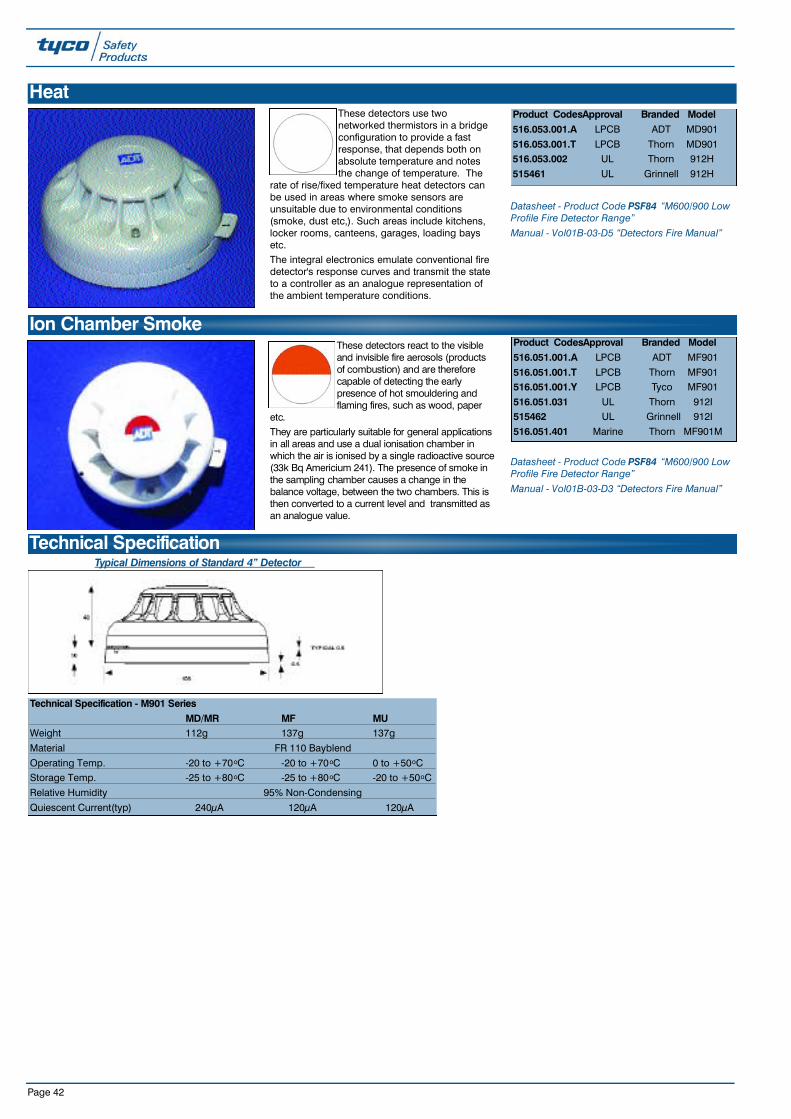
Page 42
These detectors use twonetworked thermistors in a bridgeconfiguration to provide a fastresponse, that depends both onabsolute temperature and notesthe change of temperature. The
rate of rise/fixed temperature heat detectors canbe used in areas where smoke sensors areunsuitable due to environmental conditions(smoke, dust etc,). Such areas include kitchens,locker rooms, canteens, garages, loading baysetc.The integral electronics emulate conventional firedetector's response curves and transmit the stateto a controller as an analogue representation ofthe ambient temperature conditions.
Datasheet - Product Code PSF84 “M600/900 LowProfile Fire Detector Range”Manual - Vol01B-03-D5 “Detectors Fire Manual”
HeatProduct CodesApproval Branded Model516.053.001.A LPCB ADT MD901
516.053.001.T LPCB Thorn MD901516.053.002 UL Thorn 912H
515461 UL Grinnell 912H
These detectors react to the visibleand invisible fire aerosols (productsof combustion) and are thereforecapable of detecting the earlypresence of hot smouldering andflaming fires, such as wood, paper
etc. They are particularly suitable for general applicationsin all areas and use a dual ionisation chamber inwhich the air is ionised by a single radioactive source(33k Bq Americium 241). The presence of smoke inthe sampling chamber causes a change in thebalance voltage, between the two chambers. This isthen converted to a current level and transmitted asan analogue value.
Datasheet - Product Code PSF84 “M600/900 LowProfile Fire Detector Range”Manual - Vol01B-03-D3 “Detectors Fire Manual”
Ion Chamber SmokeProduct CodesApproval Branded Model516.051.001.A LPCB ADT MF901
516.051.001.T LPCB Thorn MF901516.051.001.Y LPCB Tyco MF901
516.051.031 UL Thorn 912I515462 UL Grinnell 912I
516.051.401 Marine Thorn MF901M
Typical Dimensions of Standard 4” Detector
Technical Specification
Technical Specification - M901 SeriesMD/MR MF MU
Weight 112g 137g 137g
Material FR 110 Bayblend
Operating Temp. -20 to +70oC -20 to +70oC 0 to +50oCStorage Temp. -25 to +80oC -25 to +80oC -20 to +50oC
Relative Humidity 95% Non-Condensing
Quiescent Current(typ) 240µA 120µA 120µA
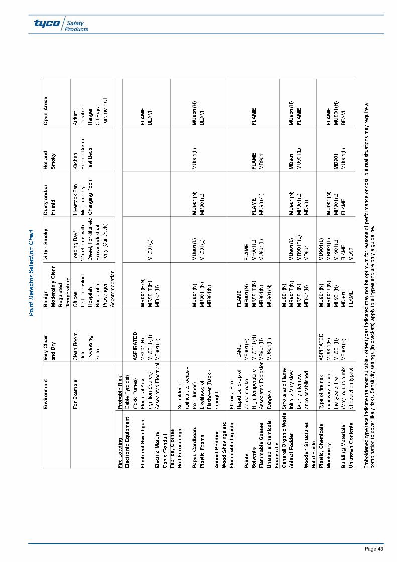
Page 43
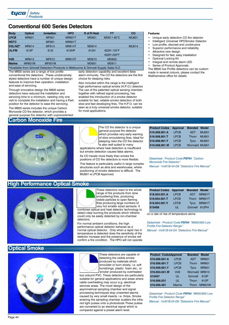
Page 44
Conventional 600 Series Detectors
The M600 series are a range of low profileconventional fire detectors. These unobtrusivelystyled detectors have a number of unique designfeatures to improve their operation, installationand ease of servicing.
Through innovative design the M600 seriesdetectors have reduced the installation andservicing time to a minimum, needing only onevisit to complete the installation and having a Parkposition for the detector to ease the servicing.
The M600 series includes the unique CarbonMonoxide CO fire detector, which provides ageneral purpose fire detector with unprecedented
early detection capability and excellent falsealarm immunity. The CO fire detectors are the firstchoice for sleeping risks.
Also included within the range is the intelligenthigh performance optical smoke (H.P.O.) detector.The use of the patented optical sensing chamber,together with refined signal processing, hasenabled the introduction of a smoke detectorsuitable for fast, reliable smoke detection of bothslow and fast developing fires. The H.P.O. can beseen as a truly universal smoke detector, suitablefor most applications.
Features• Unique early detection CO fire detector• Intelligent Universal HPOSmoke Detector• Low profile, discreet and unobtrusive• Superior performance and reliability• Attractive new design• Designed for fast, easy installation• Optional Locking Kit• Integral and remote alarm LED• Series of Product ApprovalsThe M600 low Profile detectors can be custommade in several colours, please contact theWalthamstow office for details
These detectors react to the wholerange of fire products from slowsmouldering fires, producingvisible particles to open flamingfires producing large numbers ofvery hot smaller sized aerosols. It
combines optical and heat detector technology todetect clear burning fire products which hithertocould only be easily detected by ion-chamberdetectors.For normal ambient conditions, the highperformance optical detector behaves as anormal optical detector. Only when a rapid rise intemperature is detected does the sensitivity of thedetector increase and the presence of smoke willconfirm a fire condition. The HPO will not operate
on a rate of rise of temperature alone.
Datasheet - Product Code PSF84 “M600/900 LowProfile Fire Detector Range”Manual - Vol01B-04-D4 “Detectors Fire Manual”
High Performance Optical Smoke
Body Optical Ionisation HPO R of R Heat FT COLPCB MR601 MF601 MR601T MD601 MD611 60°C MU601
NSTC MF601 MR601T
SSL/NZ* MR614 MF614 MR614T MD614 MU614UL/FM 612P 612I 612HP 612H 622H 135°F
632H 200°FVdS MR613 MF613 MR613T MD613 MD623Marine MR601M MF601M MD601 MD611
*Available from Grinnell Detection Products in Melbourne & Grinnell Supply Sales N.Z.
The CO fire detector is a uniquegeneral purpose fire detectorwhich provides very early warningof slow smouldering fires. Ideal forsleeping risks the CO fire detectoris also well suited to many
applications where heat detection is insufficientbut smoke detection causes false alarms.
As CO travels more freely than smoke thepositions of CO fire detectors is more flexible.
This feature is particularly useful in large complexstructures such as atria and warehouses, wherepositioning of smoke detectors is difficult. TheMU601 is LPCB Approved.
Datasheet - Product Code PSF94 “CarbonMonoxide Fire Detector”Manual - Vol01B-04-D8 “Detectors Fire Manual”
Carbon Monoxide Fire
These detectors are capable ofdetecting the visible smokeproduced by materials whichsmoulder or burn slowly, i.e. softfurnishings, plastic foam etc;. or'smoke' produced by overheated
but unburnt PVC. These detectors are particularlysuitable for general applications and areas wherecable overheating may occur e.g. electricalservices areas. The novel design of theasymmetrical sampling chamber and signalprocessing techniques stop unwanted alarmscaused by very small insects. i.e. thrips. Smokeentering the sampling chamber scatters the infra-red light pulses onto a photodiode These pulsesare converted to an electrical signal which iscompared against a preset alarm level.
Datasheet - Product Code PSF84 “M600/900 LowProfile Fire Detector Range”Manual - Vol01B-04-D6 “Detectors Fire Manual”
Optical Smoke
Product Codes Approval Branded Model516.058.001.A LPCB ADT MU601516.058.001.T LPCB Thorn MU601
516.058.001.Y LPCB Tyco MU601
516.058.001.W LPCB Wormald MU601
Product Codes Approval Branded Model516.054.001.A LPCB ADT MR601T
516.054.001.T LPCB Thorn MR601T
516.054.001.Y LPCB Tyco MR601T515458 UL Grinnell 612PH
Product CodesApproval Branded Model516.056.001.A LPCB ADT MR601516.056.001.T LPCB Thorn MR601
516.056.001.Y LPCB Tyco MR601
516.054.041.W VdS Wormald MR613515457 UL Grinnell 612P
516.056.031 UL Thorn 612P
516.056.401 Marine Thorn MR601M
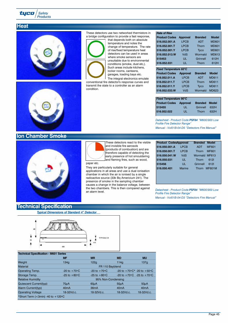
Page 45
These detectors use two networked thermistors ina bridge configuration to provide a fast response,
that depends both on absolutetemperature and notes thechange of temperature. The rateof rise/fixed temperature heatdetectors can be used in areaswhere smoke sensors areunsuitable due to environmentalconditions (smoke, dust etc,).Such areas include kitchens,locker rooms, canteens,garages, loading bays etc.The integral electronics emulate
conventional fire detector's response curves andtransmit the state to a controller as an alarmcondition.
Datasheet - Product Code PSF84 “M600/900 LowProfile Fire Detector Range” Manual - Vol01B-04-D5 “Detectors Fire Manual”
Heat
Fixed Temperature 90°CProduct Codes Approval Branded Model515455 UL Grinnell 632H516.052.022 UL Thorn 632H
Technical Specification - M601 SeriesMF MR MD MU
Weight 134g 122g 114g 137gMaterial FR 110 Bayblend
Operating Temp. -20 to +70oC -20 to +70oC -20 to +70oC* -20 to +50oC
Storage Temp. -25 to +80oC -25 to +80oC -20 to +70oC -25 to +70oCRelative Humidity 95% Non-Condensing
Quiescent Current(typ) 70µA 60µA 50µA 50µAAlarm Current(typ) 40mA 36mA 40mA 40mA
Operating Voltage 18-32Vd.c. 18-32Vd.c. 18-32Vd.c. 18-32Vd.c.
*Short Term (<3min) -40 to +120oC
Typical Dimensions of Standard 4” Detector
These detectors react to the visibleand invisible fire aerosols(products of combustion) and aretherefore capable of detecting theearly presence of hot smoulderingand flaming fires, such as wood,
paper etc.
They are particularly suitable for generalapplications in all areas and use a dual ionisationchamber in which the air is ionised by a singleradioactive source (33k Bq Americium 241). Thepresence of smoke in the sampling chambercauses a change in the balance voltage, betweenthe two chambers. This is then compared againstan alarm level.
Datasheet - Product Code PSF84 “M600/900 LowProfile Fire Detector Range” Manual - Vol01B-04-D3 “Detectors Fire Manual”
Ion Chamber Smoke
Technical Specification
Rate of RiseProduct Codes Approval Branded Model516.052.001.A LPCB ADT MD601
516.052.001.T LPCB Thorn MD601516.052.001.Y LPCB Tyco MD601
516.052.013.W VdS Wormald MD613515453 UL Grinnell 612H
516.052.031 UL Thorn 612H
Fixed Temperature 60°CProduct Codes Approval Branded Model516.052.011.A LPCB ADT MD611
516.052.011.T LPCB Thorn MD611516.052.011.Y LPCB Tyco MD611
516.052.033.W VdS Wormald MD623
Product CodesApproval Branded Model516.050.001.A LPCB ADT MF601
516.050.001.T LPCB Thorn MF601
516.050.041.W VdS Wormald MF613516.050.031 UL Thorn 612I
515456 UL Grinnell 612I
516.050.401 Marine Thorn MF601M

Page 46
Page 47
A convenient pocket sized “quick reference card”designed to aid the identification of TycoM600/M900 Series Detectors. (M900 Seriesinformation is on the reverse of card).
Product CodeAM2801/000ID Card
Note: Cards must be ordered in multiples of100.
Tyco M600/M900 Detector Series Identification Card

Page 48
Standard Detector Bases
The 4 inch base is designed to fit directly to theceiling or various common backboxes. This baseallows a detector to be fitted indirectly or afunctional base to be plugged in between thebase and detector.
Features• Variety of fixing options• Remote LED connections• Available with continuity diode fitted• Anti-tamper facility• LPCB, Vds, Marine approved (M600/900)• UL approved (4B)Product Codes517.050.001M600/900 4” Universal mounting base for LPCB,Vds approved detectors
571.070 - (K07226456)M600/900 4” Universal mounting base for LPCB,Vds approved detectors - Zettler Branded5154674B - 4” Universal mounting base for UL ApprovedDetectors - Grinnell Branded.
517.050.6014B - 4” Universal mounting base for UL ApprovedDetectors - Thorn Branded.
Datasheet - Product Code PSF101 M600/900 LowProfile Detector BasesManual - Vol01B-03-D2 “Detectors Fire Manual”
M600/900 and 4B - 4 Inch Universal Base
6” Universal BaseThe 6” base is specially designed for applicationsusing the US style single gang backbox. The 6”base provides an alternative to the 4” base inmost applications and is particularly useful wherelarge holes in the ceiling need covering or whereceilings suffer from condensation.Features• Variety of fixing options• Sealed back and cable entry• Remote LED connections• Anti-tamper facility• UL approved (6B)
Product Codes5154686B Lo Pro detector base (6”) Grinnell branded. 517.050.6066B Lo Pro detector base (6”) Thorn Securitybranded. Suitable for use with LPC and Vdsapproved detectors
The Standard Universal detector bases are compatible with both conventional (M600) and analogue (M900) addressable detectors. The bases have noelectronics and even when the detectors are connected to the bases, they can be electrically disconnected and left in a “park” position. This enables wiringintegrity tests to take place without any damage to electronics. When used with addressable detectors, the smart card access key automatically transfers tothe base, thus the address remains with the base even if the detector is changed or replaced. An optional, tool removable locking pin allows the detector tobe fixed in place to prevent tampering.
M600D Continuity Base
The M600D Continuity base is a standard 4 inchbase fitted with a continuity diode, for use with all
M600 Series detectors. The Base is designed toensure that the conventional system meets therequirements of BS5839 Pt:1 for call-pointsplaced after detectors. The M600D works with XL,NT, System 1700, MINERVA 1 to 4, MINERVAMDM520 Module.
Product Codes517.050.007M600D Diode continuity mounting base.509.018.006Active End of Line Unit for use with M600conventional detectors (not required on NT andXL panels which are supplied with special EOLdevices)
Datasheet - Product Code PSF84 “M600/900 LowProfile Fire Detector Range”Manual - Vol01B-03-D2 “Detectors Fire Manual”

Page 49
Functional Detector BasesFunctional detector bases use a common moulding which incorporates a double side circuit board which enables electrical connections to be made on thetop and bottom of the functional base. This allows the functional bases to be retrofitted into new and existing universal bases or alternatively the depth andcost of the installed detector can be reduced by using the functional base instead of the universal base. This feature enables additional line isolators andsounders to be easily added during commissioning. In addition, changes to the building during it’s life can be easily adapted to, by retrofitting sounders andrelay outputs to existing detection points.When functional bases are fitted to universal bases, they automatically lock into position. Removal is then achieved using the detector removal tool. Thisfeature ensures that the detector and functional bases are removed separately.
When used on addressable systems, the MC900 takes the same address as the detector. This increases the number of devices on a loop and significantlyimproves fault monitoring. Any attempt to remove the functional base will generate a fault on the system.
Datasheet - Product Code PSF101 “M600/900 Low Profile Detector Bases” Manual - Vol01B-03-D2 “Detectors Fire Manual”
A plastic cap which fits onto the601SB/601SBD/602SB/602SBD Sounder Base toenable these bases to operate as a sounderwithout fitting a detector.
Product Codes557.001.040.AMark II Sounder Cap (ADT Branded)557.001.040.TMark II Sounder Cap (Thorn Branded)557.001.040.YMark II Sounder Cap (Tyco Branded)
.
A new low current range of sounder bases for usewith Conventional and Addressable Fire AlarmControl Panels.
Features• Manufactured to EN54 part 3• Integral sounder and detector base• Volume and tone adjustable after installation• Low Power Synchronisation• Do not require use of a standard base (maybe
installed directly onto a standard besa box)
Product Codes577.001.035601SB Conventional Sounder Base577.001.037601SBD Conventional Diode Sounder Base577.001.036602SB 2 Wire Line Powered Sounder Base577.001.038602SBD 2 Wire Line Powered Diode SounderBase516.800.911901SB Universal Sounder Base516.800.912912SB Universal UL Sounder Base
Please See Following Applications Table forFurther Details.
Tyco MKII Sounder Bases
A simple Volume Adjustment Tool, specific to thetask of sounder volume selection on the “variable-volume” range of Tyco MKII Sounder BaseDevices.
Sounder volume can be easily varied between themaximum 90dBA and minimum 68dBA-volumesettings, using this simple, functional tool.
Note: Sounder Base Devices are supplied withthe volume pre-set to maximum volume.
Product Code517.050.015Volume Adjustment Tool
Tyco MKII Sounder Cap
Volume Adjustment Tool

Page 50
Tyco MKII Sounder Base Range Identification Card
A convenient pocket sized “quickreference card” designed to aidthe identification of the Tyco MKIISounder Base Range.
This concise card provides asimple, effective reference key forrapid identification of sounder basetype during the initial visual systemanalysis and needs assessment.
Product Code517.050.016ID Cards Note: Cards must be ordered inmultiples of 100.

Page 51
MKII Sounder Base Applications Table

Page 52
The MI900 incorporates the same circuitry as theLI520 MKII line isolator to provide a flexible andeasily installed line isolation on MINERVAanalogue addressable systems. As the lineisolator is easily inserted or removed, futuresystem changes can be implemented to suitchanges in building use with minimum disruption.
Features• Up to 12 isolators per loop• Status indication LED• Easily retrofitted• Complies with BS5839
Technical SpecificationOperating Temp.: -25 to 70°C
Humidity: Up to 96% RH (non-condensing)
Vibration: Exceeds requirements of prEN54-3 Marine & UL268
Power Supply: Loop
Product Code545.001.008MI900 Line isolator base for use with M900detectors on MINERVA systems (also compatiblewith TFX systems but not UL approved)
MI900 Analogue Addressable Loop Line Isolator
The 900 Series relay base provides dual relaycontacts for signalling external devices onaddressable systems. Very low operating current
even when the relay is energised, enable therelay base to be used without any additionalpower. On addressable systems, the dualcontacts operate when the detector is in alarmOR when commanded to do so by the panel.
Features• Dual pole 24V d.c. relay contacts (60VA)• Status indication LED• Very low power consumption (<20µA except
start up)• Can be used in place of a standard baseTechnical SpecificationOperating Temp.: -25 to 70°C
Humidity: Up to 96% RH (non-condensing)
Vibration: Exceeds requirements of prEN54-3 Marine & UL268
Power Supply: Loop/Circuit
Product Codes568.001.016MC900 Relay base (BS 5839)515591900 RBA Relay base (UL - Grinnell)
MC900 & 900RBA Functional Relay Base
Product Codes517.050.005M69 Detector locking pin kit (Pack of 100)
571.071Zettler Detector locking pin kit (Pack of 100)(K07226458)
Datasheet - PSF101 “ M600/900 Low ProfileDetector Bases”Manual - Vol01B-03-D2 “Detectors Fire Manual”
Detector Locking Pin Kit
The 600 Series relay base provides dual relaycontacts for signalling external devices on
conventional detection systems. Very lowoperating current even when the relay isenergised, enable the relay base to be usedwithout additional power. The relay contactsoperate when the detector enters the alarmcondition.
Features• Dual pole 24Vd.c. relay contact (60VA)• Status indicator LED• Low power consumption (<20µA except start
up)• Latching operation• Can be used instead of a standard base• Requires diode fitting if used in place of an
M600D diode base. Not compatible withSystem 1600 or T880 panels
Technical SpecificationOperating Temp.: -25°C to +70°CHumidity: Up to 95% RH (non
condensing)
Vibration: Exceeds requirements of prEN54-3, Marine & UL268
Product Codes568.001.018MC600 Relay base (BS5839)515590600 RBA Relay base (UL - Grinnell)
MC600 & 600RBA Functional Relay Base

Page 53
Product Code540.003.006.TRemote Indicator LED square UK singlegang mounting (Thorn Branded) for usewith conventional detectors.
Product Codes517.001.231DHM69 Deckhead mounting for M600/900 series517.001.181DHM7 Earthing strip
Product Codes517.051.008M900C Smart card address key programmer foruse with Consys515475M900C Smart Card Address key programmer forTFX (Grinnell)
Product Codes517.050.003.ACA600 Low profile line continuity adaptorcommissioning tool (provides cablecontinuity through the base) - ADTbranded517.050.003.TCA600 Low profile line continuity adaptorcommissioning tool (provides cablecontinuity through the base) - Thornbranded
Product Codes517.051.007M900F Smart card address key programmerfreestanding
515474M900F Address key programmer (Grinnell)
M600/900 Detector AncillariesM600/900 Ancillaries
Product Codes517.051.002 (Supplied in 10’s)
M900 Smart card address key 515472 (Supplied in 10’s)
900 Smart card address key (Grinnell)
517.051.402 (Supplied in 10’s)M900M Smart card address key (Marine)
Product Code517.050.002.ALow profile line shorting adaptor commissioningtool (shorts terminals together enabling cableresistance checks to be carried out) - ADTBranded.
Product Code517.050.011W500 White powder coated steel protective cagefor M600/900 series detectors also suitable formost other smoke detectors. 120mm dia x 80mmdeep

Page 54 Page 54
MP69 & MP35 Duct Probe Air SamplingProduct Codes517.025.036MP69 Duct Probe unit and base for M600/900Series
517.025.021 (PSF64)MP35 duct probe unit for M300/500 series517.001.035DP450 Probe Tube and exhaust
517.001.036DP600 Probe Tube 600mm and exhaust
517.001.037DP750 Probe Tube 750mm and exhaust
517.001.038DP900 Probe Tube 900mm and exhaust
517.001.039DP1200 Probe Tube 1200mm and exhaust517.001.040DP1500 Probe Tube 1500mm and exhaust
Datasheet - Product Code PSF91 “MP69 DuctProbe Unit” and PSF64 “Series 300/400/500 Fire &Smoke Detectors” Manual - Vol01B-06-D1 “Detectors Fire Manual”
Product Codes517.025.035SMP69 Stainless Steel Duct Probe unit anduniversal detector base for M600/900 series
517.025.027 (PSF64)SMP35 duct probe unit stainless steel forM300/500 series
517.025.028DPS450 Probe tube stainless steel and exhaust
517.025.029DPS600 Probe tube stainless steel 600mm andexhaust517.025.030DPS750 Probe tube stainless steel 750mm andexhaust
517.025.031DPS900 Probe tube stainless steel 900mm andexhaust
517.025.033DPS1500 Probe tube stainless steel 1500mm andexhaust
Datasheet - Product Code PSF92 “SMP69 DuctProbe Unit” and PSF64 “Series 300/400/500 Fire &Smoke Detectors” Manual - Vol01B-06-D1 “Detectors Fire Manual”
SMP69 & SMP35 Duct Probe Air Sampling - Stainless Steel
Duct Probe Air SamplingMP/SMP Duct Probe UnitsThe MP/SMP Duct Probe Units are designed tobe installed in air conditioning supply andexhaust ducts for the purpose of monitoring theairflow for smoke and combustion products.The MP69 and SMP69 probe units are designedto accept and operate with the M600 and M900series detectors. MP35 and SMP35 duct probeunits are available for use with M300 and M500intrinsically safe series detectors and bases. Forgeneral applications it is recommended thatphotoelectric smoke detectors rather thanionisation smoke detectors are used.
The SMP stainless steel probe unit is designed to
withstand the more demanding environments ofthe offshore oil and gas industries.
The units are designed to operate in airspeeds of1.5 to 25 metres per second. A range of samplingtubes from 450mm to 1500mm are available. Technical SpecificationOperating temperature: -20°C to +70°C
Storage temperature: -25°C to +80°CRelative Humidity: 0 to 95%
MP## "Bayblend" housing with transparentpolycarbonate coverSMP## Stainless steel 316 housing withtransparent polycarbonate cover
MP69 SMP69 MP35 SMP35Height 90mm 90mm 116mm 116mm
Width 145mm 150mm 145mm 150mm
Length 220mm 225mm 220mm 225mmWeight 0.58Kg 1.2Kg 0.35Kg 1Kg
WarningDuct probe units sited in the common duct workto several extract grills may fail to respond tosmoke from any one extract due to the effect ofdilution. The MP/SMP units will not respond toairflow of less than 1.5m/sec.
SitingDuct probe units should always be sited as near to the point of extraction from the room as possibleand in lengthy duct work runs, at intervals along the run. Probes should be mounted at the leastturbulent sections of the ducting. Avoid installation immediately behind fans, bends or work sections.
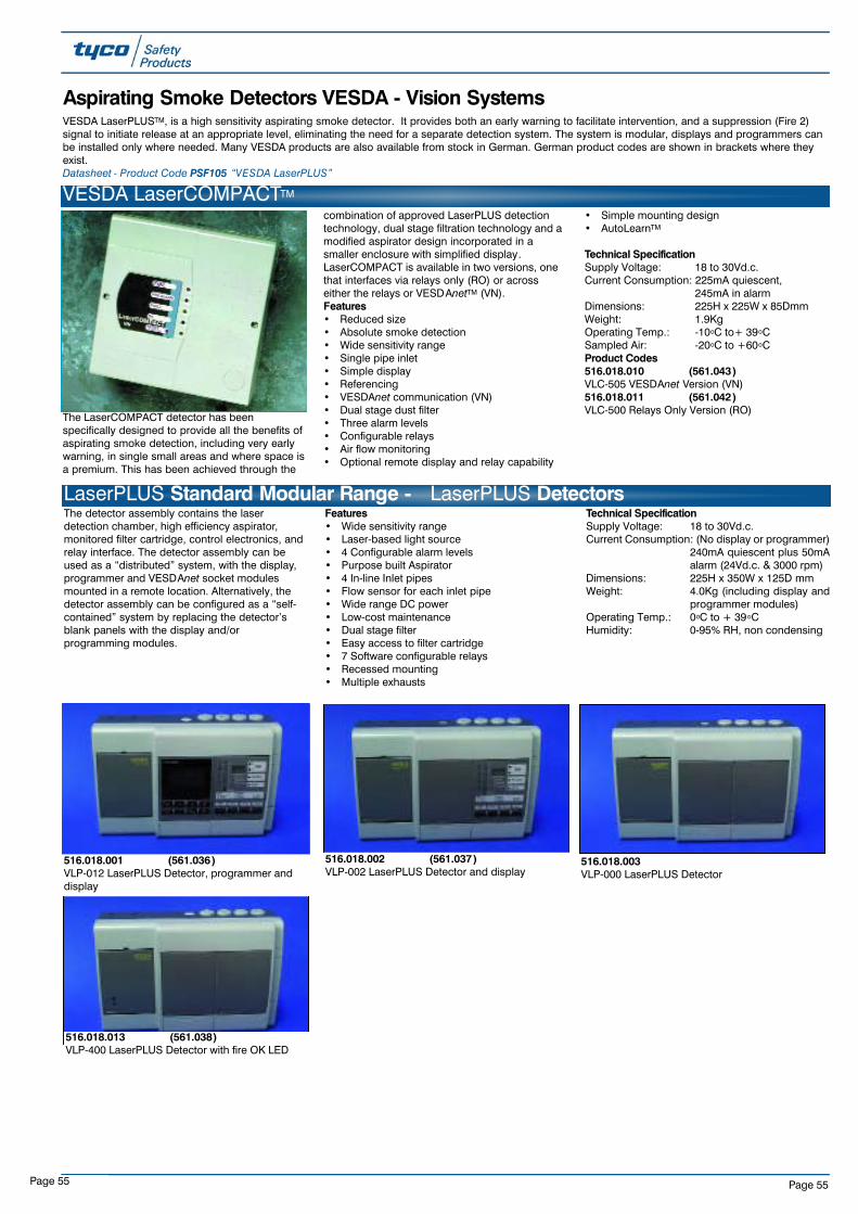
Page 55Page 55
LaserPLUS Standard Modular Range - LaserPLUS DetectorsThe detector assembly contains the laserdetection chamber, high efficiency aspirator,monitored filter cartridge, control electronics, andrelay interface. The detector assembly can beused as a “distributed” system, with the display,programmer and VESDAnet socket modulesmounted in a remote location. Alternatively, thedetector assembly can be configured as a “self-contained” system by replacing the detector’sblank panels with the display and/orprogramming modules.
Features• Wide sensitivity range• Laser-based light source• 4 Configurable alarm levels• Purpose built Aspirator• 4 In-line Inlet pipes• Flow sensor for each inlet pipe• Wide range DC power• Low-cost maintenance• Dual stage filter• Easy access to filter cartridge• 7 Software configurable relays• Recessed mounting• Multiple exhausts
Technical SpecificationSupply Voltage: 18 to 30Vd.c.Current Consumption: (No display or programmer)
240mA quiescent plus 50mAalarm (24Vd.c. & 3000 rpm)
Dimensions: 225H x 350W x 125D mmWeight: 4.0Kg (including display and
programmer modules)Operating Temp.: 0oC to + 39oCHumidity: 0-95% RH, non condensing
Aspirating Smoke Detectors VESDA - Vision SystemsVESDA LaserPLUSTM, is a high sensitivity aspirating smoke detector. It provides both an early warning to facilitate intervention, and a suppression (Fire 2)signal to initiate release at an appropriate level, eliminating the need for a separate detection system. The system is modular, displays and programmers canbe installed only where needed. Many VESDA products are also available from stock in German. German product codes are shown in brackets where theyexist.Datasheet - Product Code PSF105 “VESDA LaserPLUS”
516.018.001 (561.036)VLP-012 LaserPLUS Detector, programmer anddisplay
516.018.002 (561.037)VLP-002 LaserPLUS Detector and display
516.018.003VLP-000 LaserPLUS Detector
516.018.013 (561.038)VLP-400 LaserPLUS Detector with fire OK LED
VESDA LaserCOMPACTTM
The LaserCOMPACT detector has beenspecifically designed to provide all the benefits ofaspirating smoke detection, including very earlywarning, in single small areas and where space isa premium. This has been achieved through the
combination of approved LaserPLUS detectiontechnology, dual stage filtration technology and amodified aspirator design incorporated in asmaller enclosure with simplified display.LaserCOMPACT is available in two versions, onethat interfaces via relays only (RO) or acrosseither the relays or VESDAnetTM (VN).Features• Reduced size• Absolute smoke detection• Wide sensitivity range• Single pipe inlet• Simple display• Referencing• VESDAnet communication (VN)• Dual stage dust filter • Three alarm levels• Configurable relays• Air flow monitoring• Optional remote display and relay capability
• Simple mounting design• AutoLearnTM
Technical SpecificationSupply Voltage: 18 to 30Vd.c.Current Consumption: 225mA quiescent,
245mA in alarmDimensions: 225H x 225W x 85DmmWeight: 1.9KgOperating Temp.: -10oC to+ 39oCSampled Air: -20oC to +60oCProduct Codes516.018.010 (561.043)VLC-505 VESDAnet Version (VN)516.018.011 (561.042)VLC-500 Relays Only Version (RO)
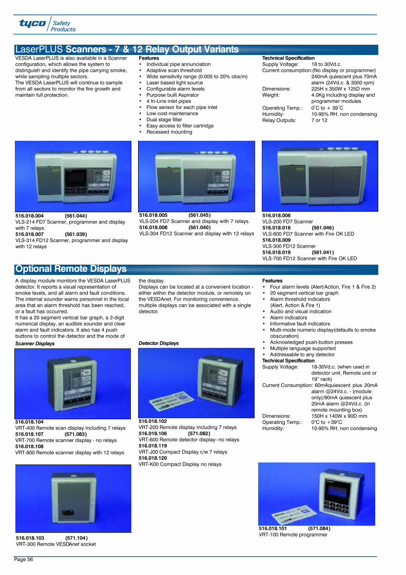
Page 56
516.018.103 (571.104)VRT-300 Remote VESDAnet socket
A display module monitors the VESDA LaserPLUSdetector. It reports a visual representation ofsmoke levels, and all alarm and fault conditions.The internal sounder warns personnel in the localarea that an alarm threshold has been reached,or a fault has occurred.It has a 20 segment vertical bar graph, a 2-digitnumerical display, an audible sounder and clearalarm and fault indicators. It also has 4 pushbuttons to control the detector and the mode of
the display.Displays can be located at a convenient location -either within the detector module, or remotely onthe VESDAnet. For monitoring convenience,multiple displays can be associated with a singledetector.
Features• Four alarm levels (Alert/Action, Fire 1 & Fire 2)• 20 segment vertical bar graph• Alarm threshold indicators
(Alert, Action & Fire 1)• Audio and visual indication• Alarm indicators• Informative fault indicators• Multi-mode numeric display(defaults to smoke
obscuration)• Acknowledged push-button presses• Multiple language supported• Addressable to any detectorTechnical SpecificationSupply Voltage: 18-30Vd.c. (when used in
detector unit, Remote unit or19” rack)
Current Consumption: 60mAquiescent plus 20mAalarm @24Vd.c. - (module only)/90mA quiescent plus 20mA alarm @24Vd.c. (in remote mounting box)
Dimensions: 150H x 140W x 90D mmOperating Temp.: 0°C to +39°CHumidity: 10-95% RH, non condensing
Optional Remote Displays
516.018.101 (571.084)VRT-100 Remote programmer
516.018.102VRT-200 Remote display including 7 relays516.018.106 (571.082)VRT-600 Remote detector display- no relays516.018.119VRT-J00 Compact Display c/w 7 relays516.018.120VRT-K00 Compact Display no relays
516.018.104VRT-400 Remote scan display including 7 relays516.018.107 (571.083)VRT-700 Remote scanner display - no relays516.018.108VRT-800 Remote scanner display with 12 relays
VESDA LaserPLUS is also available in a Scannerconfiguration, which allows the system todistinguish and identify the pipe carrying smoke,while sampling multiple sectors. The VESDA LaserPLUS will continue to samplefrom all sectors to monitor the fire growth andmaintain full protection.
Features• Individual pipe annunciation• Adaptive scan threshold• Wide sensitivity range (0.005 to 20% obs/m)• Laser based light source• Configurable alarm levels• Purpose built Aspirator• 4 In-Line inlet pipes• Flow sensor for each pipe inlet• Low-cost maintenance• Dual stage filter• Easy access to filter cartridge• Recessed mounting
Technical SpecificationSupply Voltage: 18 to 30Vd.c.Current consumption:(No display or programmer)
240mA quiescent plus 70mAalarm (24Vd.c. & 3000 rpm)
Dimensions: 225H x 350W x 125D mmWeight: 4.0Kg including display and
programmer modulesOperating Temp.: 0°C to + 39°CHumidity: 10-95% RH, non condensingRelay Outputs: 7 or 12
LaserPLUS Scanners - 7 & 12 Relay Output Variants
516.018.004 (561.044)VLS-214 FD7 Scanner, programmer and displaywith 7 relays.516.018.007 (561.039)VLS-314 FD12 Scanner, programmer and displaywith 12 relays
516.018.005 (561.045)VLS-204 FD7 Scanner and display with 7 relays.516.018.008 (561.040)VLS-304 FD12 Scanner and display with 12 relays
516.018.006VLS-200 FD7 Scanner516.018.016 (561.046)VLS-600 FD7 Scanner with Fire OK LED516.018.009VLS-300 FD12 Scanner516.018.019 (561.041)VLS-700 FD12 Scanner with Fire OK LED
Scanner Displays Detector Displays

Page 57
The 19” sub-rack is available as a mountingoption, with 4 mounting slots for display orprogramming modules.
Technical SpecificationDimensions: 128H x 482W x 120D mm
Product Codes516.018.201VSR-2000 19” Sub-rack with 1 detector displayand 3 blanks516.018.203VSR-2210 19” Sub-rack, 2 detector displays,programmer and 1 blank516.018.204VSR-2221 19” Sub-rack with 3 detector displaysand programmer516.018.206VSR-2222 19” Sub-rack with 4 detector displays
LaserPLUS Standard 19 Inch Sub-Rack Remote Display Assemblies
Standard rack enclosures are available to fit 2(see picture) or 5 sub-rack assemblies.Technical SpecificationDimensions:020-052 400H x 600W x 220D mm020-055 800H x 600W x 220D mm020-050 300H x 400W x 140D mm
Product Codes516.018.301020-052 19” Rack enclosure (2 rows)516.018.302020-055 19” Rack enclosure (5 rows)516.018.303020-050 IP65 Enclosure
LaserPLUS Standard 19 Inch Rack Remote Display Assemblies
Sub-rack configurations other than thoseavailable as standard can be supplied as custombuilt units. The sub-rack and cost of assembly areincluded in the VSR-CUSTOM.The configuration of the custom built unit must be
specified at time of ordering (e.g. 2 x VSU-0 and 2x VSU-2 configured as VSR-0022)Note: The order of the numbers (e.g. 0022)indicates the order in which the sub-units will bemounted in the sub-rack housing when lookingfrom the front of the unit - from left to rightProduct Codes516.018.260VSU-0 Blank Sub-unit516.018.261VSU-1 Programmer sub-unit516.018.262VSU-2 Detector display sub-unit plus 7 relays516.018.264VSU-4 Scanner display sub-unit plus 7 relays516.018.265VSU-5 Blank sub-unit with 7 relays
516.018.214VSU-E Blank scanner sub-unit with 7 relays516.018.268VSU-8 Scanner display sub-unit with 12 relays516.018.269VSU-9 Blank display sub-unit with 12 relays516.018.219VSU-J Compact display sub-unit plus 7 relays516.018.210VSR-CUSTOM Custom sub-rack housing includescost of custom building 4 VSU sub-rack units.
LaserPLUS Components for Ordering Custom Built Remote Display Sub-racks
A variety of other ancillaries are available. TycoSafety Products stock pipe and sampling points.
Product Codes517.017.005Sampling point label517.017.006Aspirating pipe label516.018.402 (571.086)VHX-0200 PC link HLIplus leads (MK2)516.018.403 (571.089)VSW-004 VConfig Basic software
Available on requestVSW-005 VConfig Pro software516.018.404 (571.090)VSW-002 Aspire Windows software516.018.407VESDA 24Vd.c., 2A Power supply and charger
LaserPLUS Ancillaries & Power Supply Unit
516.018.401 (571.085)VHH-100 Hand held programmer plus leads

Page 58
All VESDA LaserPLUS products are currentlysupplied from stock in Tyco grey with Englishlabels and software. Labels can be easilychanged to any of the languages below.Alternatively, where large quantities are involvedTyco Safety Products can arrange for specialdelivery of pre-labelled products - extra deliverytime must be allowed.
VESDA International Language Decals
The following common VESDA LaserPLUS sparesare kept in stock by Tyco Safety Products. Otherspares can be supplied if required.
Product Codes516.018.501VSP-002 Display (spare)516.018.502VSP-004 Scanner display (spare)516.018.503VSP-001 Programmer (spare)516.018.505VSP-019 Filter cover door (spare)516.018.506VSP-006 Spare detector chassis and manifold516.018.508VSP-008 Spare remote termination card 7 relays516.018.509VSP-009 Spare scanner chassis and manifold516.018.514VSP-014 Spare header termination card 7 relays516.018.515VSP-015 Spare aspirator fan
LaserPLUS Spares
516.018.504VSP-005 Filter cartridge (spare)
Language VESDA Scanner VESDA Detector
Swedish 516.018.270 -
German 571.088 571.087

Page 59
Approvals
Interface BASEEFA FM Product Codes
Conventional 4-20mA Addressable Relay Ex ‘ia’ Ex ‘d’ Ex ‘d’
S231i+ 516.037.004S231f+ 516.037.003
S232f+ 516.037.015S241i+ 516.038.004
S241f+ 516.038.003S251i+ 516.039.004S251f+ 516.039.003
S252f+ 516.039.015S261f+ 516.040.002
S262f+ 516.040.012
S200 Plus Triple IR Solar Blind Flame Detector
The MINERVA S200 PLUS flame detectors arethe latest Infrared solar blind and multi-channelinfra-red flame detectors with low powerconsumption and high false alarm immunity.The MINERVA S200 PLUS range of advancedflame detectors is the most comprehensive rangeavailable.
Features• Triple waveband infrared solar blind flame
detection for optimum false alarm immunity• Unrivalled black body rejection over a wide
range of source temperatures• Range adjustable to 50 metres for a 0.1m-2
petrol pan fire• Discrimination of optical faults (dirty windows)
from other faults by the built-in self test• Housing designed for easy installation of
cabling• Flexible mounting and angular adjustment• 3 x 20mm field cable entries• IP66/67 housing designed for external use• Rugged stainless steel ANC4 LM25 alloy
housing and mounting bracket• Operating temperature range of -40 to + 80°C• Variable response times and sensitivity
settings• Remote self test and range setting• True window test in detection area (i.e. not in
the edge of the window)
• Terminals provided for Remote LEDconnection
• BASEEFA (CENELEC) certified• Meets the requirements of EN54 Pt10• FM, DNV and LRS certified• Very low power consumption (0.35mA)• Models available with Conventional or
Analogue Addressable interface (requires 2core cable only)
• Models also available with relay or 4-20mAoutputs
• Patented dual filter solar blindness forcomplete solar blindness
• 100°field of view on IS versions• 90° field of view on Flameproof versions
Unlike other flame detectors on the market theMINERVA S200 PLUS is available in bothIntrinsically Safe (EEx ia) and Flameproof (EEx d)models.
The intrinsically safe models are suffixed by theletter " i " and meet the requirements of EN50020part 7 and are BASEEFA certified EEx ia IIC T5.As part of an intrinsically safe circuit, it is suitablefor zones 0,1 and 2 where group IIC gases orlesser hazards can be continuously present inexplosive concentrations.
The flameproof models are suffixed by the letter"f" and meet the requirements of EN50018 andare BASEEFA certified EEx d IIC T6. Thedetectors are suitable for zones 1 and 2 wheregroup IIC gases or lesser hazards can beintermittently present in explosive concentrations.
Technical SpecificationDetector Material: Stainless Steel 316LDimensions: 167H x 167W x 89D MM
Weight: 4.5Kg
Gland Entry: 3 x 20mm
Metal Parts: Bright Stainless Steel 316
(external & internal) to BS1449 Pt 2
Tag Label: Stainless Steel 316
Range: 0.1m2 petrol at 50m0.4m2 petrol at 60m
Response Time: Field Selectable 3,6 and 12s
Sensitivity: 3 range settingsRelative Humidity: 95% (100% intermittent)
Enclosure to: IP 66 and IP 67
For information on flame detector test equipment,please refer to the detector test equipmentsection.ApprovalsBASEEFA Approved models are suffixed ‘1’.
NSTC: ApprovedLPCB: Approved
LRS: Approved
DNV: ApprovedKFEIC: Approved
SSL: ApprovedMCA: Approved
FM Approved models are suffixed ‘2’. .
Datasheet - Product Code PSF102 “Minerva S200Plus Series”
Special Hazard Detectors
Product Codes592.001.016T210 Test source for use with (517.001.224 ) Solo704 Adaptor Tube B and Solo 100/101 Poles(517.001.230/226)592.001.014T210 Adaptor required for the T210 to be usedwith S200 and S200 Plus Flame detectors
Datasheet - Product Code PSF60 “T110/T210 TestSource”Manual - Vol01A-01-G1 “Detectors Fire Manual”
S200 Series Test Equipment

Page 60
The S131 has been specially packaged in a toughGRP anti-static housing with abrasion resistantsapphire windows and protection against wateringress under sustained, high wind driven
conditions. The S131 Infra-red Flame Detectoruses the same optical and electronic module asthe S111 and S121 detectors. It therefore hasnear identical performance characteristics makingit completely blind to solar radiation whetherdirect, reflected or modulated.Technical SpecificationMaterial: G.R.P. Anti-static, black
Dimension: 160H x 160W x 90D mm(without bracket)
Weight: 2.85 Kg (including bracket)
Gland Entry: 2 x 20mmRange: 0.1m2 petrol at 20m
0.4m petrol at 40m
Field of View: 90° min inclusive
Response Time: 3 secs min5-10 secs typical
Product Codes516.009.023S131 Infra-red Flame detector solar blind
516.009.028S131 Infra-red Flame detector solar blindPyrotronics
Datasheet - Product Code PSF58 “S131 FlameDetector”Manual - Vol01A-04-D4 “Detectors Fire Manual”
The S161 Infra-Red Flame Detector is specificallydesigned to replace installed UV units usingexisting Ex d wiring, making replacement highlycost effective.
The S161 Infra-Red Flame Detector uses thesame optical and electronic module as the S111,S121 and S131 detectors. It therefore, hasidentical performance characteristics making it
completely blind to solar radiation whether direct,reflected or modulated. In order to meet thedemands of arduous environments, such aschemical plants and off-shore oil and gasplatforms, the S161 detector has been packagedin a tough G.R.P. anti-static housing, which makesit mechanically similar to the S131 detector.
Two 20mm cable entries and two 4-way terminalblocks are provided, which eliminate the need fora local junction box, reducing installation costs.When using the existing Ex‘d’ wiring associatedwith UV detectors, the use of BASEEFA certifiedEx ‘e’ glands is mandatory.Technical SpecificationSupply Voltage: 18.0V to 24.0 V d.c. (polarity
conscious)
Quiescent Current: 100µ A max. at 20V d.c.Alarm Current: 2-wire, latching.
720 ohm in series with typically 4V switched acrosssupply
Alarm Indication: Red LED
Connections: Two 4 way 2.5mm heavy duty terminal blocks
Hazardous Area: BASEEFA Ex e s ib IIC T5. Suitable for use in zones 1 and 2 where group IIC gases or lesser hazards are sometimes present in explosive concentrations.
BASEEFA Cert. No: EX87Y 3550
Product Code516.009.022S161 Infra-red Flame detector solar blindcomplete with built in intrinsically safe isolation.
Datasheet - Product Code PSF59 “S161 FlameDetector”Manual - Vol01A-04-D5 “Detectors Fire Manual”
S161 Flame Detector
S131 Flame Detectors
The S111 and S121(and variants thereof) are single sensor infra-redflame detectors with optical filtering, suitable foruse outdoors in a wide range of applications.Specifically designed for use in the demandingenvironments of the onshore petro-chemicalindustry, the S111 and S121 detectorsincorporate an abrasion resistant sapphirewindow in a protective housing to meet IP65.
Features• No false alarms from welding, sunlight or high
intensity lamps• Low maintenance costs• Quick response to carbon fires• Good performance (20m)• Completely solar-blind for use outdoors• High sensitivity with exceptional interference
rejection• BASEEFA approved EEx ia IIC T5• Housing protection to IP65• Integral stainless steel 316 mounting bracket• 2 core interface to conventional fire systems
• Built in response indicator• High immunity to smoke, dust and grimeTechnical SpecificationMaterial: Impact resistant moulded
plastic (light grey)
Dimensions: 160H x 80W x 60D mm (without bracket)
Weight: 0.6Kg
Gland Entry (S121): 1 x 20mmRange: 0.1m2 petrol at 20m
0.4m petrol at 40m
Field of View: 85° min inclusiveResponse Time: 3 secs min, 5-10 secs
typical
Supply Voltage: 15.5 to 25.5Vd.c.
Quiescent Current: 100µA max. at 20Vd.c.Alarm Current: 60 mA max
Operating Temp.: -30°C (-40°C with reduced range) to + 70°C
Storage Temp.: -40°C to + 80°CRelative Humidity: 95% (100% intermittent)
Enclosure to: IP65
Classification: BASEEFA EEx ia IIC T5 Suitable for use in zones 0,1and 2 where group IIC gasses or lesser hazards are present in explosive concentrations.
BASEEFA Cert No.: Ex 812333
ConnectionsS111 Milspec plug sealed into body
Milspec mating socket with 2m of 4 core PVCinsulated, braid screened PVC sheathed cable
to DEF Std 61-12 Pts 4S121 One 4 way, 2.5 mm heavy duty terminalblock
Product Codes516.009.006S111 Infra-red Flame detector solar blind plugand socket connection
516.009.008S121 Infra-red Flame detector solar blind screwterminal connections516.009.014S121 Infra-red Flame detector solar blind screwterminal connections (Pyrotronics) FM Approved
516.009.007S112 Infra-red Flame detector non solar blindplug and socket connection
516.009.019S122 Infra-red Flame detector non solar blindscrew terminal connections (Pyrotronics)
Datasheet - Product Code PSF22 “S111/121 InfraRed Flame Detector”Manual - Vol01A-04-D1/D2/D3 “Detectors FireManual”
S111 and S121 Series Flame Detectors
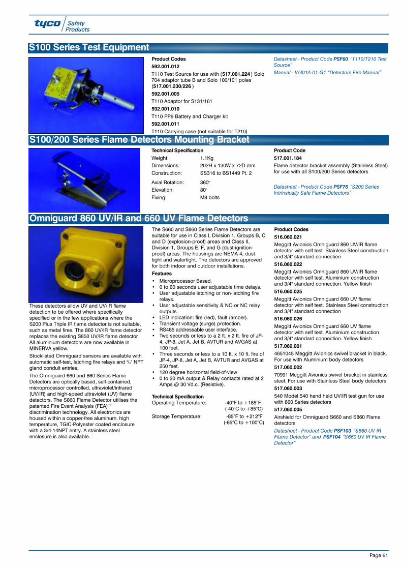
Page 61
Omniguard 860 UV/IR and 660 UV Flame Detectors
These detectors allow UV and UV/IR flamedetection to be offered where specificallyspecified or in the few applications where theS200 Plus Triple IR flame detector is not suitable,such as metal fires. The 860 UV/IR flame detectorreplaces the existing S850 UV/IR flame detector.All aluminium detectors are now available inMINERVA yellow.Stocklisted Omniguard sensors are available withautomatic self-test, latching fire relays and 3/4" NPTgland conduit entries.
The Omniguard 660 and 860 Series FlameDetectors are optically based, self-contained,microprocessor controlled, ultraviolet/infrared(UV/IR) and high-speed ultraviolet (UV) flamedetectors. The S860 Flame Detector utilises thepatented Fire Event Analysis (FEA)™discrimination technology. All electronics arehoused within a copper-free aluminum, hightemperature, TGIC-Polyester coated enclosurewith a 3/4-14NPT entry. A stainless steelenclosure is also available.
The S660 and S860 Series Flame Detectors aresuitable for use in Class I, Division 1, Groups B, Cand D (explosion-proof) areas and Class II,Division 1, Groups E, F, and G (dust-ignition-proof) areas. The housings are NEMA 4, dust-tight and watertight. The detectors are approvedfor both indoor and outdoor installations.
Features• Microprocessor Based.• 0 to 60 seconds user adjustable time delays.• User adjustable latching or non-latching fire
relays.• User adjustable sensitivity & NO or NC relay
outputs.• LED indication: fire (red), fault (amber).• Transient voltage (surge) protection.• RS485 addressable user interface.• Two seconds or less to a 2 ft. x 2 ft. fire of JP-
4, JP-8, Jet A, Jet B, AVTUR and AVGAS at100 feet.
• Three seconds or less to a 10 ft. x 10 ft. fire ofJP-4, JP-8, Jet A, Jet B, AVTUR and AVGAS at250 feet.
• 120 degree horizontal field-of-view • 0 to 20 mA output & Relay contacts rated at 2
Amps @ 30 Vd.c. (Resistive).
Technical SpecificationOperating Temperature: -40°F to +185°F
(-40°C to +85°C)
Storage Temperature: -85°F to +212°F (-65°C to +100°C)
Product Codes516.060.021Meggitt Avionics Omniguard 860 UV/IR flamedetector with self test. Stainless Steel constructionand 3/4" standard connection
516.060.022Meggitt Avionics Omniguard 860 UV/IR flamedetector with self test. Aluminium constructionand 3/4" standard connection. Yellow finish
516.060.025Meggitt Avionics Omniguard 660 UV flamedetector with self test. Stainless Steel constructionand 3/4" standard connection516.060.026Meggitt Avionics Omniguard 660 UV flamedetector with self test. Aluminium constructionand 3/4" standard connection. Yellow finish
517.060.0014651045 Meggitt Avionics swivel bracket in black.For use with Aluminium body detectors
517.060.00270991 Meggitt Avionics swivel bracket in stainlesssteel. For use with Stainless Steel body detectors517.060.003540 Model 540 hand held UV/IR test gun for usewith 860 Series detectors517.060.005Airshield for Omniguard S660 and S860 Flamedetectors
Datasheet - Product Code PSF103 “S860 UV IRFlame Detector” and PSF104 “S660 UV IR FlameDetector”
S100/200 Series Flame Detectors Mounting BracketTechnical SpecificationWeight: 1.1KgDimensions: 202H x 130W x 72D mm
Construction: SS316 to BS1449 Pt. 2
Axial Rotation: 360o
Elevation: 80o
Fixing: M8 bolts
Product Code517.001.184Flame detector bracket assembly (Stainless Steel)for use with all S100/200 Series detectors
Datasheet - Product Code PSF76 “S200 SeriesIntrinsically Safe Flame Detectors”
S100 Series Test EquipmentProduct Codes592.001.012T110 Test Source for use with (517.001.224 ) Solo704 adaptor tube B and Solo 100/101 poles(517.001.230/226 )
592.001.005T110 Adaptor for S131/161
592.001.010T110 PP9 Battery and Charger kit592.001.011T110 Carrying case (not suitable for T210)
Datasheet - Product Code PSF60 “T110/T210 TestSource”Manual - Vol01A-01-G1 “Detectors Fire Manual”
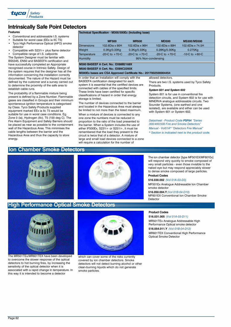
Page 62
Ion Chamber Smoke Detectors
Intrinsically Safe Point DetectorsFeatures• Conventional and addressable I.S. systems• Suitable for worst case (EEx ia IIC T5)• Tyco High Performance Optical (HPO) smoke
detector• Compatible with S231i+ plus flame detector• Compatible range of I.S. callpointsThe System Designer must be familiar withBS5345, EN50 and BASEEFA certification andhave successfully completed an Appropriaterecognised course in Intrinsic Safety. Design ofthe system requires that the designer has all theinformation concerning the installation correctlydocumented. The nature of the Hazard must bedefined by the customer and a survey carried outto determine the proximity of the safe area toestablish cable runs.
The probability of a flammable mixture beingpresent is defined by a Zone Number. Flammablegases are classified in Groups and their minimumspontaneous ignition temperature is categorisedby Class. Tyco Safety Products suppliedequipment marked EEx ia IIc T5 would besuitable for use in worst case conditions. Eg.Zone 0 (ia), Hydrogen (IIc), T5 (100 deg C). TheFire Alarm Equipment and Safety Barriers shouldbe placed as near as possible to the containmentwall of the Hazardous Area. This minimises thecable lengths between the barrier and theHazardous Area and thus the capacity to storeenergy.
In order that an Installation will comply with theBASEEFA certification designated for eachsystem it is essential that the certified devices areconnected with cables of the specified limits.These limits have been certified for specificclassifications of hazard in order that energystorage is limited.
The number of devices connected to the barrierand located in the Hazardous Area must alwaysbe limited to not more than the listed maximum.
When a mixture of devices is connected to anyone zone the numbers must be reduced inproportion to the ratio of the load presented tothe barrier. When a System includes the use ofeither IF500Ex, S231i+ or S251i+, it must beremembered that the load they present to thecircuit is twice that of a detector. A mixture oflarge and small load devices connected to a zonewill require a calculation for the number of
allowed detectors.
There are two I.S. systems used by Tyco SafetyProducts.
System 601 and System 602System 601 is for use in conventional firedetection circuits, and System 602 is for use withMINERVA analogue addressable circuits. TwoSounder Systems, (one earthed and oneisolated), are available and either can be usedwith System 601 or System 602.
Datasheet - Product Code PSF64 “Series300/400/500 Fire and Smoke Detectors” Manual - Vol01A* “Detectors Fire Manual” * Section is indicated next to the product code.
The ion chamber detector [type MF501EX/MF601Ex]will respond very quickly to smoke composed ofvery small particles - even those invisible to thenaked eye but may respond appreciably slowerto dense smoke composed of large particles.Product Codes516.030.002 (Vol 01A-03-D3)MF501Ex Analogue Addressable Ion Chambersmoke detector516.050.004.Y (Vol 01B-04-D10)MF601EX Conventional Ion Chamber SmokeDetector
The MR501TEx/MR601TEX have been developedto overcome the slower response of the opticaldetectors to hot burning fires, by increasing thesensitivity of the optical detector when it isassociated with a rapid change in temperature. Inthis way it is intended to become a detector
which can cover some of the risks currentlycovered by ion chamber detectors. Smokedetectors will not detect burning alcohol or otherclean-burning liquids which do not generatesmoke particles.
Product Codes516.031.005 (Vol 01A-03-D11)MR501TEx Analogue Addressable HighPerformance Optical smoke detector516.054.011.Y (Vol 01B-04-D12)MR601TEX Conventional High PerformanceOptical Smoke Detector
High Performance Optical Smoke Detectors
Technical Specification - M300/500Ex (Including base)
MF500 MR500 MD500 MS300/MS500Dimensions 102.6Dia x 90H 102.6Dia x 96H 102.6Dia x 89H 102.6Dia x 74.5HWeight 0.3Kg/0.33Kg 0.3Kg/0.33Kg 0.28Kg/0.30Kg 0.275Kg
Temperature -20oC to +70oC -20oC to +70oC -20oC to +70oC -10oC to +60oCHumidity 95% Non-condensing
M300 BASEEF A Cert. No.: EX88B2168XM500 BASEEF A Cert. No.: EX89C2200XM300Ex bases are CSA Approved Certificate No.: 2017002500004454
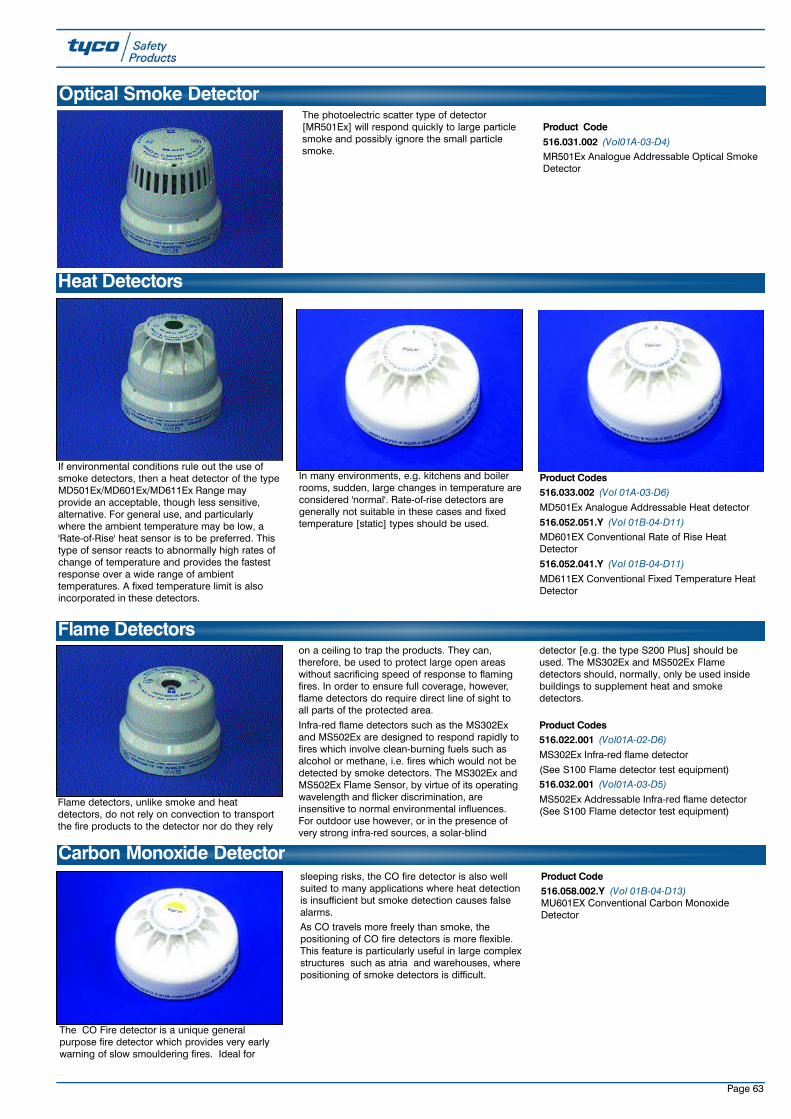
If environmental conditions rule out the use ofsmoke detectors, then a heat detector of the typeMD501Ex/MD601Ex/MD611Ex Range mayprovide an acceptable, though less sensitive,alternative. For general use, and particularlywhere the ambient temperature may be low, a'Rate-of-Rise' heat sensor is to be preferred. Thistype of sensor reacts to abnormally high rates ofchange of temperature and provides the fastestresponse over a wide range of ambienttemperatures. A fixed temperature limit is alsoincorporated in these detectors.
In many environments, e.g. kitchens and boilerrooms, sudden, large changes in temperature areconsidered 'normal'. Rate-of-rise detectors aregenerally not suitable in these cases and fixedtemperature [static] types should be used.
Product Codes516.033.002 (Vol 01A-03-D6)MD501Ex Analogue Addressable Heat detector
516.052.051.Y (Vol 01B-04-D11)MD601EX Conventional Rate of Rise HeatDetector
516.052.041.Y (Vol 01B-04-D11)MD611EX Conventional Fixed Temperature HeatDetector
Heat Detectors
Page 63
Flame detectors, unlike smoke and heatdetectors, do not rely on convection to transportthe fire products to the detector nor do they rely
on a ceiling to trap the products. They can,therefore, be used to protect large open areaswithout sacrificing speed of response to flamingfires. In order to ensure full coverage, however,flame detectors do require direct line of sight toall parts of the protected area.
Infra-red flame detectors such as the MS302Exand MS502Ex are designed to respond rapidly tofires which involve clean-burning fuels such asalcohol or methane, i.e. fires which would not bedetected by smoke detectors. The MS302Ex andMS502Ex Flame Sensor, by virtue of its operatingwavelength and flicker discrimination, areinsensitive to normal environmental influences.For outdoor use however, or in the presence ofvery strong infra-red sources, a solar-blind
detector [e.g. the type S200 Plus] should beused. The MS302Ex and MS502Ex Flamedetectors should, normally, only be used insidebuildings to supplement heat and smokedetectors.
Product Codes516.022.001 (Vol01A-02-D6)MS302Ex Infra-red flame detector
(See S100 Flame detector test equipment)516.032.001 (Vol01A-03-D5)MS502Ex Addressable Infra-red flame detector(See S100 Flame detector test equipment)
Flame Detectors
The photoelectric scatter type of detector[MR501Ex] will respond quickly to large particlesmoke and possibly ignore the small particlesmoke.
Product Code516.031.002 (Vol01A-03-D4)MR501Ex Analogue Addressable Optical SmokeDetector
Optical Smoke Detector
The CO Fire detector is a unique generalpurpose fire detector which provides very earlywarning of slow smouldering fires. Ideal for
sleeping risks, the CO fire detector is also wellsuited to many applications where heat detectionis insufficient but smoke detection causes falsealarms.As CO travels more freely than smoke, thepositioning of CO fire detectors is more flexible.This feature is particularly useful in large complexstructures such as atria and warehouses, wherepositioning of smoke detectors is difficult.
Product Code516.058.002.Y (Vol 01B-04-D13)MU601EX Conventional Carbon MonoxideDetector
Carbon Monoxide Detector

Page 64
Product Codes517.025.002M300Ex Mounting base517.035.002M500Ex Mounting base517.025.010M300/M500 Base lock kit517.050.610MUBEX Mounting Base
517.025.022MB35 Flush mounting kit for M300/400/500 series517.035.006M500 Protective cover517.001.231DHM69 Deckhead mounting kit. This deckheadmounting is also suitable for 300/500 seriesdetectors.517.001.120System 601 EOL Unit (Pk 10)
M300/500/MUBEX Detector Bases and Ancillaries
Constructed from stainless steel, the T54B is anextremely rugged heat detector that can be usedto detect fires in the harshest of environments.The T54B can be used in environments withambient temperatures up to 200oC and, beinghermetically sealed, is impervious to mostcontaminants.
The T54B is suitable for use in areas withexplosive atmospheres. Certified as a flameproof(Ex d) device, it can be used in Zone 1 and Zone2 hazardous areas when installed usingflameproof mounting enclosures and conduit.
Classified as a simple device, the T54B can beused in Zone 0 areas when connected to asuitable intrinsically safe barrier. For reliableoperation, it is recommended that T54B detectorshave set points 20oC or 20% (whichever is higher)above the maximum temperature they will beexposed to in normal operation.
Preferred factory preset temperatures are:
60, 90, 100, 145oC; normally with open contacts.Technical SpecificationOperating voltage @ 0.5A: 240Va.c. to
24Vd.c.
Switching Current: 5 to 500mAContact Resistance: <1 ohm
Actuating Temp.:(factory set) 60 to 240oC
Fixed Temp. Only: *Type EAccuracy: + or - 5%
Ambient Temp.: -40 to +270oCRelative Humidity: 100% RH
Protection Category: IP67
Thread Size: M20 x 1.5mm
Product Codes516.033.011T4E60X T54B Point Type heat detector - 60oC516.033.012T4E90X T54B Point Type heat detector - 90oC
516.033.013T4E100X T54B Point Type heat detector - 100oC
516.033.014T4E145X T54B Point Type heat detector - 145oCOther temperatures and normally closed contactsare available by request.
514.001.017IF500Ex Intrinsically safe addressable interfacesuitable for T54B probes
Datasheet - Product Code PSF24 “System 601/602for Hazardous Areas”
Olsen T54B - Point Type Heat Detector
The MDU601EX detector combines the featuresof both the MU601EX detector and the MD601EXdetector to provide a combined CO and Rate ofRise Heat Detector where the sensitivity of the COdetector is enhanced in response to a fast rate ofchange of temperature.
Product Code516.016.001.Y (Vol 01B-04-D14)MDU 601EX Enhanced Carbon Monoxide Fire& Heat Detector
Enhanced Carbon Monoxide Fire & Heat Detector

Page 65
The and H900 range of fixed temperature heatdetectors are designed to operate at 60oC and90oC respectively. They are particularly suited toareas where rapid changes in temperature and/orhigh ambient temperature exist, together withunsuitable environmental conditions for smokedetectors. This makes the detectors ideally suitedfor galleys, laundries etc.Features• Approved by Marine classification authorities• Two wire supervised circuit• Draws no quiescent current
• Self re-setting• Special versions can be used in any Zone 1 or
Zone 2 environment• Grade 3 to European Standard EN54 Part 5
1977Technical SpecificationOperating Voltage: up to 24V d.c.Quiescent Current: zeroAlarm Current: Limited by internal 390 ohm
or 50 ohm resistorDimensions: 82mm dia x 41mmWeight: 73gmMaterial: Cycolac ABSOperating temp. range: -20 oC to +100oCRelative Humidity: up to 100% RH (Non
Condensing)Alarm Temp: H6XX: 60oC
H9XX: 90oCProduct Codes517.001.130DHM8 (including 2 x 20mm glands)
516.014.017H600 60oC Fixed temp. Grade 1516.014.021H601 60oC Fixed temp. Grade 1 (Remote LEDInd.)516.014.019H602 60oC Fixed temp. Grade 1 (Integral LEDInd.)516.014.025H604 60oC Fixed temp. Grade 1 (Integral LEDInd.) Intrinsically Safe - Simple Apparatus516.014.018H900 90oC Fixed temp. Grade 1516.014.020H902 90oC Fixed temp. Grade 1 (Integral LEDInd.)516.014.026H904 90oC Fixed temp. Grade 1 (Integral LEDInd.) Intrinsically safe - Simple Apparatus
Datasheet - Product Code PSF108 “H Series FixedTemperature Detectors”
H Series Heat Detectors
The SM87BG/CP530 is based on the popularMEDC SM87BG explosion proof EEx ‘d’ callpointbreak glass and is BASEEFA approved under theTyco brand name with an integral CP530addressable callpoint module suitable for use onall MINERVA 8,16E and 80 analogue addressablesystems.Technical SpecificationMEDC Reference: SM87BGLAD1R1L0NRMaterial: LM25TF Marine Grade AlloyCertification: EExd IIC T6IP rating: IP67BASEEFA No.: SM87 ADDRESSABLE
UNIT C (A) Ex85B1037Weight: 2.7kgDimensions: 122H x 122W x 105D mmMounting Holes: 4 x 9mm diameter (105 x
105mm centres)
Entries: 1 x M20 ISO right hand side plus 1 x M20 ISO left handside
Text: FIRE - BREAK GLASSFinish: Red Epoxy PaintTag label: None fitted as standardNOTE: Stainless steel option available, contactProduct Management Department, Sunbury formore details.Product Codes514.001.055 (Vol08A-02-D34)EExd MEDC SM87BG heavy duty alloybreakglass with integral CP530 pottedaddressable module514.001.056Spare glass and ‘O’ ring assembly for SM87BG
SM87BG/CP530 Explosion Proof Addressable Callpoint
This manual fire alarm call point is designed inaccordance with the latest draft European CallPoint Standad (EN54-11).Weatherproof to IP66 and available certifiedintrinsically safe, simple apparatus or uncertified,the units are manufacured from glass reinforcedpolyester (GRP) which provides a robust,corrosion free construction and ensures effectiveand reliable operation in harsh industrial andoffshore environments.
Units are supplied in self coloured GRP with a‘Burning House’ duty label as standard.
Product Codes514.001.059Intrinsically Safe Callpoint (BG3I4NBN)514.001.061Simple Apparatus Callpoint (BG3W4NBN)514.001.058Weatherproof Callpoint (BG3W4LBN)
BG3 Weatherproof and Intrinsically Safe Conventional Callpoint
MODEL BG3I Simple Apparatus/BG3W
PROTECTION Explosion Protected EExia(Intrinsically Safe) Dust-tight & Weatherproof
CENELEC EN50014, 020BASEEFA EExia IIC T4
CERTIFICATION Cert No. BAS00ATEX1067X Not ApplicableSuitable for use in Zones 0,1, & 2
VOLTAGE Up to 28V (IS) Up to 250 V a.c.
CERTIFIED TEMPERATURE -55°C TO +55°C Not Applicable
INGRESS PROTECTION IP66 IP66
EUROPEAN STANDARD FOR CALLPOINTS EN54-11 EN54-11
TERMINALS 6 X 4.0mm2 6 X 4.0mm2
DC: 0 - 30V 3A resistive or inductive30V - 50V 1A resistive or inductive
SWITCH RATINGS Not Applicable AC: 0 - 250V 3A resistive or inductive
CABLE ENTRIES 2 X M20 Top or Bottom 2 X M20 Top or Bottom
WEIGHT 0.5Kg 0.5Kg
MATERIAL UV resistant glass reinforced polyester UV resistant glass reinforced polyester
FINISH Natural Red GRP Natural Red GRP
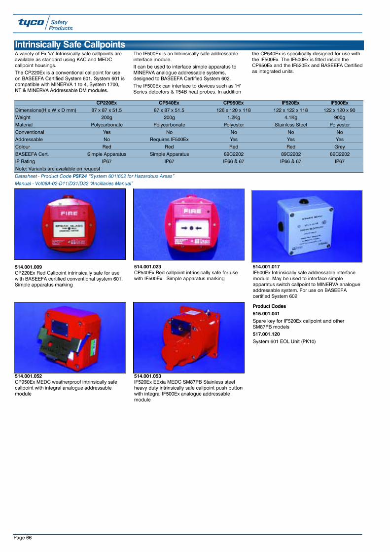
Page 66
514.001.009CP220Ex Red Callpoint intrinsically safe for usewith BASEEFA certified conventional system 601.Simple apparatus marking
514.001.017IF500Ex Intrinsically safe addressable interfacemodule. May be used to interface simpleapparatus switch callpoint to MINERVA analogueaddressable system. For use on BASEEFAcertified System 602
514.001.023CP540Ex Red callpoint intrinsically safe for usewith IF500Ex. Simple apparatus marking
514.001.052CP950Ex MEDC weatherproof intrinsically safecallpoint with integral analogue addressablemodule
514.001.053IF520Ex EExia MEDC SM87PB Stainless steelheavy duty intrinsically safe callpoint push buttonwith integral IF500Ex analogue addressablemodule
Intrinsically Safe CallpointsA variety of Ex ‘ia’ Intrinsically safe callpoints areavailable as standard using KAC and MEDCcallpoint housings.The CP220Ex is a conventional callpoint for useon BASEEFA Certified System 601. System 601 iscompatible with MINERVA 1 to 4, System 1700,NT & MINERVA Addressable DM modules.
The IF500Ex is an Intrinsically safe addressableinterface module.It can be used to interface simple apparatus toMINERVA analogue addressable systems,designed to BASEEFA Certified System 602.
The IF500Ex can interface to devices such as ‘H’Series detectors & T54B heat probes. In addition
the CP540Ex is specifically designed for use withthe IF500Ex. The IF500Ex is fitted inside theCP950Ex and the IF520Ex and BASEEFA Certifiedas integrated units.
CP220Ex CP540Ex CP950Ex IF520Ex IF500ExDimensions(H x W x D mm) 87 x 87 x 51.5 87 x 87 x 51.5 126 x 120 x 118 122 x 122 x 118 122 x 120 x 90Weight 200g 200g 1.2Kg 4.1Kg 900g
Material Polycarbonate Polycarbonate Polyester Stainless Steel Polyester
Conventional Yes No No No NoAddressable No Requires IF500Ex Yes Yes Yes
Colour Red Red Red Red Grey
BASEEFA Cert. Simple Apparatus Simple Apparatus 89C2202 89C2202 89C2202IP Rating IP67 IP67 IP66 & 67 IP66 & 67 IP67
Note: Variants are available on request
Product Codes515.001.041Spare key for IF520Ex callpoint and otherSM87PB models517.001.120System 601 EOL Unit (PK10)
Datasheet - Product Code PSF24 “System 601/602 for Hazardous Areas” Manual - Vol08A-02-D11/D31/D32 “Ancillaries Manual”
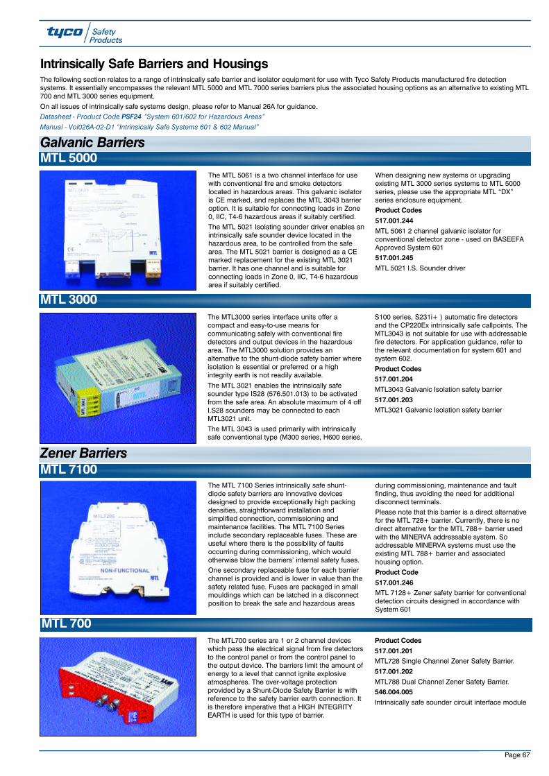
Page 67
The MTL700 series are 1 or 2 channel deviceswhich pass the electrical signal from fire detectorsto the control panel or from the control panel tothe output device. The barriers limit the amount ofenergy to a level that cannot ignite explosiveatmospheres. The over-voltage protectionprovided by a Shunt-Diode Safety Barrier is withreference to the safety barrier earth connection. Itis therefore imperative that a HIGH INTEGRITYEARTH is used for this type of barrier.
Product Codes517.001.201MTL728 Single Channel Zener Safety Barrier.
517.001.202MTL788 Dual Channel Zener Safety Barrier.546.004.005Intrinsically safe sounder circuit interface module
MTL 700
The MTL3000 series interface units offer acompact and easy-to-use means forcommunicating safely with conventional firedetectors and output devices in the hazardousarea. The MTL3000 solution provides analternative to the shunt-diode safety barrier whereisolation is essential or preferred or a highintegrity earth is not readily available.
The MTL 3021 enables the intrinsically safesounder type IS28 (576.501.013) to be activatedfrom the safe area. An absolute maximum of 4 offI.S28 sounders may be connected to eachMTL3021 unit. The MTL 3043 is used primarily with intrinsicallysafe conventional type (M300 series, H600 series,
S100 series, S231i+ ) automatic fire detectorsand the CP220Ex intrinsically safe callpoints. TheMTL3043 is not suitable for use with addressablefire detectors. For application guidance, refer tothe relevant documentation for system 601 andsystem 602.
Product Codes517.001.204MTL3043 Galvanic Isolation safety barrier
517.001.203MTL3021 Galvanic Isolation safety barrier
MTL 3000
Intrinsically Safe Barriers and HousingsThe following section relates to a range of intrinsically safe barrier and isolator equipment for use with Tyco Safety Products manufactured fire detectionsystems. It essentially encompasses the relevant MTL 5000 and MTL 7000 series barriers plus the associated housing options as an alternative to existing MTL700 and MTL 3000 series equipment.
On all issues of intrinsically safe systems design, please refer to Manual 26A for guidance.Datasheet - Product Code PSF24 “System 601/602 for Hazardous Areas”Manual - Vol026A-02-D1 “Intrinsically Safe Systems 601 & 602 Manual”
Galvanic Barriers
The MTL 5061 is a two channel interface for usewith conventional fire and smoke detectorslocated in hazardous areas. This galvanic isolatoris CE marked, and replaces the MTL 3043 barrieroption. It is suitable for connecting loads in Zone0, IIC, T4-6 hazardous areas if suitably certified.The MTL 5021 Isolating sounder driver enables anintrinsically safe sounder device located in thehazardous area, to be controlled from the safearea. The MTL 5021 barrier is designed as a CEmarked replacement for the existing MTL 3021barrier. It has one channel and is suitable forconnecting loads in Zone 0, IIC, T4-6 hazardousarea if suitably certified.
When designing new systems or upgradingexisting MTL 3000 series systems to MTL 5000series, please use the appropriate MTL “DX”series enclosure equipment.Product Codes517.001.244MTL 5061 2 channel galvanic isolator forconventional detector zone - used on BASEEFAApproved System 601517.001.245MTL 5021 I.S. Sounder driver
MTL 5000
The MTL 7100 Series intrinsically safe shunt-diode safety barriers are innovative devicesdesigned to provide exceptionally high packingdensities, straightforward installation andsimplified connection, commissioning andmaintenance facilities. The MTL 7100 Seriesinclude secondary replaceable fuses. These areuseful where there is the possibility of faultsoccurring during commissioning, which wouldotherwise blow the barriers’ internal safety fuses.One secondary replaceable fuse for each barrierchannel is provided and is lower in value than thesafety related fuse. Fuses are packaged in smallmouldings which can be latched in a disconnectposition to break the safe and hazardous areas
during commissioning, maintenance and faultfinding, thus avoiding the need for additionaldisconnect terminals.Please note that this barrier is a direct alternativefor the MTL 728+ barrier. Currently, there is nodirect alternative for the MTL 788+ barrier usedwith the MINERVA addressable system. Soaddressable MINERVA systems must use theexisting MTL 788+ barrier and associatedhousing option.
Product Code517.001.246MTL 7128+ Zener safety barrier for conventionaldetection circuits designed in accordance withSystem 601
MTL 7100Zener Barriers

Page 68
Safety Enclosures
UC Series EnclosuresThe UC series of enclosures provides a simplebut effective means of mounting and protectingthe MTL3000 series units, in safe areas. Astandard lightweight enclosure with transparentlid, which can accommodate 4 units. Thepolycarbonate enclosures are impact resistant,flame retardant, and dustproof to IP65.
ProductCode517.001.196UC2 4, Way Barrier housing
The MT series of enclosures provides a simple,effective means of mounting and protectingMTL700 Series barriers in safe areas or low-riskhazardous areas. Three lightweight polycarbonateenclosures with see through lids accommodateup to 2, 5 and 12 barriers in the safe area. All theenclosures are supplied ready fitted with a nickelplated brass busbar mount, so barriers can beinstalled and wired up immediately withoutspecial tools.
Product Codes517.001.198MT2 2,Way Zener Barrier Housing.517.001.199MT5 5,Way Zener Barrier Housing.
517.001.200MT12 12,Way Zener Barrier Housing
MT Series Enclosures
The ERL7 earth rail is a nickel plated 3 x 10mmrail (1 metre long), suitable for a do-it-your selfmounting arrangement. It will accommodate up to2.5 ETM7 earth terminals per barrier location forterminating earth returns and cable screens fromthe hazardous area.
The IMB7 mounts on a flat surface or top hat rail(35mm) or G-profile rail and acts as a convenientmethod for mounting the earth busbar.
Product Codes517.001.205ERL7 Earth rail I.S. systems
517.001.206ETM7 Earth termination connection system517.001.207IMB7 Insulating mounting block517.001.120System 601 EOL Unit (PK10)
Ancillaries
DX Series EnclosuresThe MTL ‘DX’ Series enclosure equipment isdesigned to house MTL 5000 isolating interfacesand MTL 7000 series shunt diode safety barriers.Enclosures are usually selected on the number ofunits they will accommodate. The following tableshows the capacity of each of the enclosuretypes.
ProductCodes517.001.248DX070 Enclosure MTL 5000/7000 series barriers
517.001.247DX170 Enclosure for MTL5000/7000 seriesbarriers
Enclosure MTL5000 Isolators 16mm Pitch MTL7000 Barriers 7.5mm PitchDX070 4 (2*) 9 (5*)
DX170 10 (8*) 22 (18*)
* Use these figures when two IMB57 mounting brackets for tagging/earth rail accessories are included

Page 69
Optical Beam Smoke DetectorsBeam and Linear Heat Detectors
The FIRE-RAY 2000 is an active infra-red smokedetector. The system comprises of three baseelements i.e. a transmitter, receiver and ControlUnit. Analysis of the modulated infra-red beam bythe Control Unit determines whether smoke ispresent, and if so generates an alarm signal.Features• Range 5 metres up to 100 metres• Area coverage up to 1400m 2
• Selectable sensitivity• Self-check and automatic compensation• Manual or automatic reset• Optional MINERVA loop powered interface
module (LPBD 521) • Suitable for both conventional and
addressable fire systems• Fire/fault interface to MINERVA controller• Low current consumption• Flexible system design options• Robust metal construction• Designed to conform to BS5839 Part 5Product Codes516.015.006.AFireRay2000 optical beam smoke detector
VdS approved, ADT Branded516.015.006.TFireRay2000 optical beam smoke detector
VdS approved, Thorn Branded
920450FireRay2000 -UL Optical beam smoke detector -UL approved
516.015.007FireRay2000 Retro-Reflector 100 x100mm516.015.008FireRay2000 Alignment tool
Spares515484FireRay2000 Spare Transmitter515485FireRay2000 Spare Receiver
515487FireRay2000 Spare Main PCB
Datasheet - Product Code PSF85 “Fireray 2000Optical Beam Smoke Detectors” Manual - Vol08A-02-D26 “Ancillaries Manual”
Technical SpecificationDimensions(mm) Weight
Height Width Depth (Kg)
Transmitter/Receiver 95 75 115 0.4Control Unit 260 210 80 2.25
LPBD521 (with M520 encl.) 87 148 14 0.1
Operating Temp. Range - Fireray -10oC to +55oC
LPBD521 -20oC to +70oC
Humidity up to 95% RH(Fireray 2000 & LPBD521) (Non-condensing)
Fireray 2000 Enclosure IP54
Voltage Range- Fireray 2000 +11.5 to +28Vd.c.
LPBD521 28V Loop PowerFireray 2000 Quiescent Current <13mA
Fireray 2000 Alarm Current <20mA
The FIRE-RAY 50/100R is a reflective infra-redbeam smoke detector. The system comprises oftwo base elements i.e. a combined infra-redtransmitter and receiver in a common housingand a reflective prism. The electronics of thecombined transmitter and receiver unit analysethe reflected beam from the prism for smoke andgenerates an alarm condition if a pre-determinedlevel is reached.
Features
• Range 5 to 50 metres (50R)
• Range 50 to 100 metres (100R)
• Area of coverage up to 750m2
(50R), 1500m2
(100R)
• Selectable sensitivity
• Self-check and automatic compensation
• Manual or Automatic Reset
• Optional MINERVA loop powered interfacemodule (LPBD521)
• Suitable for both Conventional andAddressable Systems
• Fire/Fault Interface to the Minerva Controller
• Low current consumption
• Flexible System Design Options
• Robust ABS Construction
• Designed to Conform to BS5839 Part 5, EN54Part 12, UL and VdS
Product Codes516.015.011Fire Ray 50R 5 to 50 Metre Reflective BeamDetector516.015.012Fire Ray 100R 50 to 100 Metre Reflective BeamDetector
Fire-Ray 50/100R
Technical SpecificationDimensions(mm) Weight
Height Width Depth (Kg)
Transmitter/Receiver 210 130 120 0.7
LPBD521 (with M520 encl.) 87 148 14 0.1
Voltage Range - Fire Ray 50/100R +10.2 to +30VdcLPBD521 28V Loop Power
Fire Ray 50/100R Quiescent Current <4mA @ 24VdcFire Ray 50/100R Alarm Current 15mA
Operating Temp Range - Fire Ray 50/100R -30°C to + 55°CLPBD 521 -20°C to + 70°C
Ingress Protection IP50(Fire Ray 50/100R)

Page 70
The LPBD521 module is used to drive the FireRay
2000 beam detector units directly from theMINERVA loop. A single LPBD521 can be used topower the analyser unit, the beam receiver unitand the transmitter unit. Alternatively, twoseparate LPBD521's can be used with one topower the analyser unit and receiver units and thesecond to drive the transmitter separately, eitherfrom the same loop or a different loop. Up to 12LPBD521's can be used per loop.
The module is addressable and will therefore takeone address on the loop.
Technical SpecificationPowered: Loop
Temperature Range: -20oC to+70oC
Operating Humidity: up to 95% RH non-condensing
Dimensions (PCB): 60H x 84W x 14D mmProduct Code557.180.217LPBD521 loop powered beam detector interfacemodule for use with FireRay 2000
Datasheet - Product Code PSF85 “Fireray 2000Optical Beam Smoke Detectors” Manual - Vol08A-02-D26 “Ancillaries Manual”
LPBD521 - Loop Powered Beam Detector Module
The LD40 linear heat detection system is used tomonitor fire (or overheat) conditions in confinedor polluted areas or where there are adverse orunusually variable environmental conditions. Thesensor cable is unaffected by dust, moisture orvibration and requires little maintenance.
Features• Easy and cost effective installation• Good sensitivity with adjustable alarm
threshold• Open and short circuit monitoring• Suited for outdoor and indoor applications• Can be used in hazardous areas• Mechanical protection is provided for cables in
areas where damage may occur• Chemical resistance sheathing is available for
areas where petro-chemical corrosion mayoccur.
Technical SpecificationDimensions: 170H x 105W x 111D mmWeight: 0.55KgOperating Temp: -25oC to +70oCRelative humidity: Up to 98% RH non-
condensingRating: IP55Operating Voltage: +8 to +30Vd.c.Quiescent Current: 60-80µA
Product Codes516.016.005LD40 High resistance sensor cable blue - 200Mreel516.016.006LD40 High resistance sensor cable black - 200Mreel (Nylon sheath suitable for petrochemicalexposure)516.016.010LD40 EOL Termination kit516.016.011LD40 In-line Jointing kit516.016.012LD40 Analyser module with conventionaldetection zone interface. Requires a DM520 orsimilar zone module interface to MINERVA/TFXaddressable loops
Datasheet - Product Code PSF42 “LD40 LinearHeat Detection System”
Linear Heat Detection

Page 71
This new technology uses a laser light source tolaunch light signals into an optical fibre. Aspulses travel down the fibre, energy is lostthrough scattering. A fraction of the scatteredsignal is retained within the fibre. A portion of thisis directed back along the fibre towards the lasersource - this signal is called backscatter. Part ofthe back scatter signal (Raman Scattering) isused to provide accurate remote temperaturemeasurements at hundreds of points along thefibre.
The MXF100 uses standard communicationsgrade optical fibre of the 62.5/125 graded indexmultimode type. The temperature range ispredominantly a function of the coating used toprotect the optical fibre as the fibre itself is wellbehaved over a temperature range from -50oC toapproximately 300oC.
Optical fibre itself offers several advantages as asensing medium. The signals are immune toelectromagnetic interference thereby ensuringintegrity of readings from electrically noisy areas.As no electrical current is used in the sensingfibre and the fibre is relatively inert and dielectric(non-conducting) medium, it is safe technology touse in hazardous environments.
Features
• Fibre optic sensor loop up to 2km
• Continuous temperature profiles oftemperature on a PC
• Programmable functions
• Programmable number of fire detection zones
• Multiple and programmable Alarm levels perfire detection zone
• Variable rate of rise function
• Unrivalled response times
• Optional outputs
• Modbus Serial Data
• Direct to PC
• Volt free contacts
• Insensitive to EMI
• Intrinsically safe sensor
• Uses standard communications grade opticalfibre
• Choice of cable construction
• Cable construction for extreme environments
• High System Integrity
• Automatic failure mode analysis
• Loop break recovery operation
• Diagnostic capability
• Fire progression monitoring
• No cable maintenance
• Modem for remote communications
Technical SpecificationThe MXF100 system complies with:• EMCDirective 89/336/EEC
• Low Voltage Directive 72/2/EEC
The MXF100 contains a Class 3a Laser productand complies with:• BS7192 (1989)
• American National Standard Z136.2 (1988)
• International Electrotechnical CommissionStandard 825 (1990)
Supply Voltage: 24V d.c. (-6/+12V d.c.)Power Consumption:20W maxSupply Current: <1AFuse Rating: <2A (anti-surge)Fibre: 62.5/125 graded index multi-
modeOperating Temp.: 0oC to +40oCStorage Temp.: -40oC to +65oCHumidity: 0 to 95% RH (non-
condensing)Product Codes516.016.111MXF100 Fibre Optic Linear Heat Detection controlunit c/w 3 tier wall mounted cabinet and PSU.516.016.112MXF-SL Sensor Line Thermoplastic sensor cable(1km reel) 516.016.113MXF-SS Sensor Tube Stainless Steel SensorCable (1km reel).
Datasheet - Product Code PSF111 “MXF100Optical Fibre Temperature Sensing Technology”
MXF Optical Fibre Temperature Sensing
MXF100 FUNCTIONAL BL OCK DIAGRAM
INTERNALREFERENCE
FIBRESWITCH
LASER &RECEIVER
OPTIC SCONTROL
POWERSUPPLY
DATAACQUISITION
DATAPROCESSOR
OPTIC S
ELECTRONIC S
RELAY PCB1
RELAY PCB2
RELAY PCB3
SIGNAL CONTROL
POWER SIGNAL
24Vd.c. RELAY CONNECTORSRS232 PORT 1TO PC
RS232 PORT 2 MODBUSOR SERIAL D ATA

Page 72
Detector Test Equipment
Point Detector Testing/Commissioning Equipment
Product Code517.001.255SOLO330 Aerosol dispenser for use with alldetector ranges. Connects directly toSOLO100/101 poles
Product Code517.001.224SOLO704 Adaptor tube B - Adapts SOLO100/101pole sets for TYCO detector changers and testers
Product Codes517.001.233CO Detector field test kit with 24 brickets for usewith SOLO 330
517.001.234CO Fire detector field test kit spare bricks
(Pack of 24)
Product Code517.001.256Suretest Solo aerosol tester can. For use withSOLO 330 dispenser. Non-flammable, ozone andenvironment friendly. Approx 200 tests per can
Product Code 517.050.004M69 Detector changer for use with M600/M900series. Requires Adaptor B and SOLO 100 pole
Product Code517.001.240SOLO200 Universal detector changer for use withvarious manufacturers detectors - not suitable forM600/900 series low profile. Connects directly toSOLO100/101 poles
Product Codes517.001.254SOLO461 Cordless heat detector tester kitincluding SOLO460 tester, SOLO720 batterybatons and SOLO724 charger. (Connects directlyto SOLO100/101 poles).
517.001.242SOLO720 Spare battery baton for use with SOLO450/460 tester
517.001.243SOLO724 Spare mains/car battery charger forSOLO720 battery baton
Product Code517.025.026T35 Skirt changer tool for use with M300/400/500series requires Adaptor B and SOLO100 pole
Product Codes517.001.230SOLO100 Telescopic pole 1.26M to 4.5M long517.001.226SOLO101 Extension tube 1.13M long for use with517.001.230 Telescopic extension pole
517.001.264SOLO 610 Protective Carry/Storage Bag for SoloDetector Test Kit
Manual - Vol01A & Vol01B “Detectors Manual”

Page 73
S100 Series Test Equipment
S200 Series Test Equipment
592.001.016T210 Test source for use with (517.001.224 )SOLO 704 Adaptor Tube B and SOLO100/101poles (517.001.230/226 )
592.001.014T210 Adaptor for S200 Detectors
592.001.012T110 Test Source for use with (517.001.224 )SOLO 704 Adaptor Tube B and SOLO100/101poles (517.001.230/226 )592.001.010T110 PP9 Battery and Charger kit
592.001.011T110 Carrying case (not suitable for T210)
592.001.005T110 Adaptor for S131/161 Detectors
SOLO TEST EQUIPMENT FOR POINT & FLAME DETECTORS
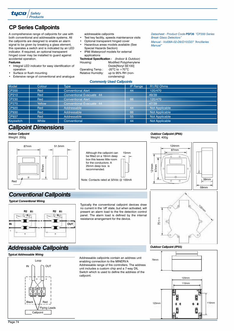
Page 74
CP Series CallpointsA comprehensive range of callpoints for use withboth conventional and addressable systems. Allthe callpoints are designed to enable an alarmsignal to be given by breaking a glass element,this operates a switch and is indicated by an LEDindicator. If required, an optional transparenthinged cover may be installed to guard againstaccidental operation.Features• Integral LED indicator for easy identification of
operation• Surface or flush mounting• Extensive range of conventional and analogue
addressable callpoints• Test key facility, speeds maintenance visits• Optional transparent hinged cover• Hazardous areas models available (See
Special Hazards Section)• IP66 Waterproof models for external
applicationsTechnical Specification - (Indoor & Outdoor)Housing: Modified Polyphenylene
Oxide[Noryl SE100]Operating Temp.: -20oC to +70oCRelative Humidity: up to 95% RH (non-
condensing)
Datasheet - Product Code PSF36 “CP200 SeriesBreak Glass Detectors” Manual - Vol08A-02-D9/D10/D27 “AncillariesManual”
Typically the conventional callpoint devices drawno current in the ‘off’ state, but when activated, willpresent an alarm load to the fire detection controlpanel. The alarm load is defined by the internalresistance arrangement for the device.
Addressable callpoints contain an address unitenabling connection to the MINERVAAddressable range of fire controllers. The addressunit includes a custom chip and a 7-way DILSwitch which is used to define the address of thecallpoint.
R2 R1 R2 R1
-
IN OUT
Typical Conventional Wiring
Callpoint
Loop
Black
IN
Red
OUT
-
Flying Leads
+
Typical Addressable Wiring
+ -
87mm
Red
51.5mm
15mmAlthough the callpoint canbe fitted on a 16mm deepbox this leaves little roomfor the conductors: A25mm deep box isrecommended.
Note: Contacts rated at 32Vdc @ 100mA
Indoor Callpoint Weight: 200g
124mm
87mm
39mm
59mm
Outdoor Callpoint (IP66) Weight: 400g
Outdoor Callpoint (IP55)
Callpoint Dimensions
Conventional Callpoints
Addressable Callpoints
79mm
123mm
110mm
123mm 110mm
Model Colour Type IP Range R1/R2 OhmsCP200 Red Conventional Alert 44 120/470CP210 Red Conventional Evacuate 44 49/39CP230 Red Conventional Alert 66 120/470CP270 Yellow Conventional Evacuate 44 47/39CP920 Red Addressable 44 Not ApplicableCP930 Red Addressable 66 Not ApplicableCP937 Red Addressable 55 Not ApplicableKeyswitch White Conventional 44 Not Applicable
Commonly Used Callpoints

Page 75
Conventional CP230 CallpointThe CP230 is an IP66 red weatherproof callpointwith LED indicator and LPCB approved.Product Codes514.001.010.ACP230 ADT branded514.001.010.TCP230 Thorn branded514.001.010.YCP230 Tyco branded
Conventional CP210 CallpointThe CP210 is a red indoor callpoint with LEDindicator and evacuate resistors. The CP210 isLPCB approved and is supplied without abackbox.Product Codes514.001.043.ACP210 ADT branded514.001.043.TCP210 Thorn Security branded514.001.043.YCP210 Tyco branded
The CP211 is a red indoor callpoint with evacuteresistors and LED indicator. (For use with theMXC/MXCE Panels only).
514.001.060.TCP211 Without backbox - Thorn SecurityBranded Lid514.001.060.YCP211 Without backbox - Tyco Branded Lid514.001.060.ACP211 Without backbox - ADT Branded Lid
Conventional CP200 Callpoint
Other Conventional Callpoints & KeyswitchesProduct Code514.002.002.AWhite keyswitch in callpoint housing. English‘Bomb Alert’ marking with ADT branded lid
Conventional CP270 CallpointProduct Code514.001.014CP270 Yellow callpoint ‘Evacuate’ complete withLED indicator without backbox - LPCB approved.
The CP200 is a red indoor callpoint with ‘alert’resistors and LED indicator. The CP200 is LPCBapproved.
Product Codes514.001.042.TCP200 without backbox - Thorn Security brandedlid514.001.042.YCP200 without backbox - Tyco branded lid514.001.057CP200E without backbox, European ‘Fire’marking and glass, unbranded lid514.001.006CP200A complete with surface backbox. Arabictext. Thorn Security branded514.001.042.ACP200 without backbox-ADT branded lid90-110Standard KAC KR-1 Flush Callpoint (No resistorsfitted)70-133Standard KAC KR72-680 Flush Callpoint (680 Ohms resistance)

Page 76
Product Codes514.001.012CP260M Marine callpoint complete with LEDindicator - IP66514.001.013CP250M Marine callpoint complete with LEDindicator surface mount
514.001.046CP520 Red addressable callpoint with LEDindicator without backbox - Marine approved andThorn Security branded lid
514.001.022CP530 Red addressable IP66 weatherproofcallpoint complete with LED indicator - Marineapproved and Thorn Security branded lid
Special Marine Callpoints
Product Code 90-106Test keys for all CP200/500/900 callpoints exceptCP950Ex
Callpoint Ancillaries
The CP920 is a red addressable callpoint withLED indicator. The CP920 is LPCB approved andsupplied without backbox.Product Codes514.001.049.ACP920 ADT branded 514.001.049.TCP920 Thorn Security branded514.001.049.YCP920 Tyco Branded
CP920 MINERV A Addressable Callpoint
The CP930 is a red addressable IP66weatherproof callpoint with LED indicator. TheCP930 is LPCB approved.Product Codes514.001.050.ACP930 ADT branded514.001.050.TCP930 Thorn Security branded514.001.050.YCP930 Tyco branded
514.001.512Addressable potted module used in the CP530and CP930 callpoints
CP930 MINERV A Addressable Callpoint
515.001.026Black callpoint bezel for CP200/500/900
515.001.028Callpoint hinged cover for use on CP200 andCP900 models
90-107Red M141 spacer for red CP200/900 KACcallpoints
The CP937 is a red addressable IP55 outdoorcallpoint with the same functionality as theCP930. The CP937 is based on the KAC Series7000.Product Code 514.001.054.ACP937 Callpoint ADT branded
CP937 MINERVA Addressable Callpoint

Page 77
The callpoint STOPPER provides protection frommalicious or accidental activation of manualcallpoints. Available for flush or surface mountedcallpoints the ‘STOPPER’ is also available withoptional high pitch sounder which is activatedwhen the lid is lifted.An optional ‘Break-Seal’ fitting kit allows ‘Break-Seals’ to be used to provide extra protection.WARNING:-Break seals only to be fitted byagreement with relevant fire authorities.The STOPPER is suitable for all callpoints up to100mm square, including CP820, CP920, CP200and other indoor KAC style callpoints.
Product Code515.001.033IPO36 Break Seal Kit
STOPPER
STOPPER STOPPER II With Sounder WeatherproofProduct Code Ref Flush Surface515.001.029 STI6530 4515.001.030 STI6531 4515.001.036 STI6535 4 4515.001.034 STI1230 4515.001.035 STI3150 4 4515.001.031 STI6532 4 4515.001.032 STI6533
MillimetresA 137B 140C 104D 45E 12.5F 12.5G 185H 12.5
STOPPER Dimensions
Flush Fit Surface Fit(+30mm)
Stopper STI6530 STI6531Stopper with Sounder STI6532 STI6533
MillimetresA 70B 16C 197D 50E 178F 146G 228H 254
STOPPER II Dimensions
Stopper II Surface Fit - STI1230
S T O P P E R STOPPER IIMax. Callpoint Size 100 x 100mm 160 x 160 mmMax. Callpoint Depth 57.5 1 2 0
(+30mm Surface)

Page 78
STOPPER II is constructed as the STOPPER fromtough injection moulded polycarbonate.Physically larger than the STOPPER theSTOPPER II extends the number of products towhich these tough multi-purpose covers canprotect.It consists of a strong tamper-proof clearpolycarbonate cover and frame that fits easilyover such products as break glass callpoints. TheSTOPPER II can also be fitted with an integralbattery powered sounder which activates if thecover is lifted.The STOPPER II is suitable for callpoints up to
160mm square like the DIN820/830 and CP830.Product Code515.001.034STI1230 Surface fit STOPPER II
STOPPER II
The Weather STOPPER and Weather STOPPERIIextends the life of weather exposed devices, suchas break glass callpoints, by offering protectionagainst harsh conditions and environments.Experience has shown that this protective covercan extend the life of products installed in salineatmospheres, such as oil rigs and ship decks.While offering environmental protection theWeather STOPPER and Weather STOPPER IIareconstructed from tough durable polycarbonatewhich will also guard against tampering,vandalism or accidental operation of devices suchas emergency switches.Product Codes515.001.036STI6535 Surface fit Weather STOPPER515.001.035STI3150 Surface fit Weather STOPPERII
Weather STOPPER & Weather STOPPER II
The Smoke Beam/CCTV Guard is manufacturedfrom tough coated steel rod and is designed toprotect projected beam detectors or CCTVcameras from vandalism or accidental damage.Suitable for use with System Sensor, Hochiki andFireray 2000 detectors.Technical SpecificationDimensions: 260H x 200W x 321D mm
Product Code516.015.009STI9625 Smoke beam/CCTV guard
Smoke Beam/CCTV Guard
The Extinguisher STOPPER is a self poweredelectronic security device which can be installedand protecting fire extinguishers in minutes. TheExtinguisher STOPPER is an effective way to stopvandalism, misuse or theft. This simple selfcontained device incorporates a unique andpatented steel cable operated switch mechanism,which activates a piercing alarm when theextinguisher is removed from its normal position.One end of the operating cable is crimped andsecured around the neck of the extinguisher andinserted into the alarm unit. If the operating cableis detached from the unit a 10dB sounder isactivated.
Product Codes515.001.038STI6200 Extinguisher STOPPER515.001.039CO23 Spare key for extinguisher stopper
Extinguisher STOPPER
STI6535 STI3150
The Exit STOPPER is a completely self containedand self powered security device to protect anddeter the unauthorised use of emergency exitdoors. It is a versatile, reliable and extremely easyto install electronic door alarm. If the door isopened the Exit STOPPER activates a 110dBelectronic sounder. A key operated over-ridefacility is incorporated into the front of the unit,which will allow authorised use of the emergencydoor.The Exit STOPPER is injection moulded in flameretardant polycarbonate and can be easily
installed on wooden, glass or metal doors. Thereare also options for remote and double doorinstallation.The unit comes complete with low batterywarning, automatic reset facility, a choice ofsteady pulsating tones, a 9V long life alkalinebattery and installation pack.
Product Code515.001.037STI6400 Red Exit STOPPER
Exit STOPPER

Page 79
Callpoint Spare Glasses - Current Product Codes515.001.014CP200/500/900 Spare glasses, white Arabic texton clear background (Pack 5)515.001.023CP200/500/900 spare glasses forCP200N/CP500N, white dutch text on clearbackground (Pack 5)515.001.027Deformable operating unit “glass” with Englishtext for use in place of glasses, for kitchens orother areas where glass is not acceptable
Callpoint Spare Glasses - Old
5 1 5 . 0 0 1 . 0 2 5CP200/500/900 Glasses, clear English text onwhite background. No logo (Pack 5). Fitted asstandard to English CP200/500 and 900C a l l p o i n t s
515.001.024CP200/500/900 spare glasses, whiteArabic/English text with Thorn Security logo onwhite background (Pack 5)
515.001.003ZF121 Callpoint glass (Pack 10) for servicespares. The ZF121 is a square metal fronted AFAMINERVA callpoint typically used on Firefinder,System 1100, ZF/System 1200, CP and CTsystems
515.001.009CP100A glass unscored (Pack 10) for servicespares. The CP100A has a large square glass tothe edge of the callpoint. Used on the same AFAsystems as the ZF121.
Ancillaries - Back BoxesUnless stated the CP200/500/900 indoor callpoints are supplied as flush mount units. The CP range are approved for use with the standard backbox.However, SR2-T and SR3-T backboxes are also available.
515.001.021Standard Red surface mounting back box forCP200/500 & 900 indoor callpoints
10-115SR2-T Optional Back Box (2 terminals)
95-131SR3-T Optional Back Box (3 terminals)
This tough polycarbonate breakglass keybox isavailable to protect emergency keys anddocuments.
Product Code515.001.039STI6720 Keybox with printed glass
Keybox
515.001.010Walsall callpoint glasses (Pack 10) for servicespares. The Walsall callpoint is an old squarecallpoint with round glass

Page 80
Fulleon Range of Sounders
The 24 Vdc Symphoni Sounder is a generalpurpose internal sounder, available either as avery high output sounder for noisy areas, or ahigh output low current sounder for applicationswhere power is limited. Both versions share thesame horn and backbox which has double cableentries for ease of installation.
The low power version has 3 selectable toneswhich may be employed for one, two or threestage alarm applications. The high output versionhas 32 selectable tones and retains full tonecompatibility with the Roshni, Squashni andAskari product ranges.
Product Codes576.501.200SY/R Low Power Red Symphoni Sounder (3 tone)
576.501.201SY/W Low Power White Symphoni Sounder (3 tone)576.501.202SYHO/R High Output Red Symphoni Sounder (32 tone)576.501.203SYHO/W High Output White Symphoni Sounder(32 tone)
MXCE 2 Wire Symphoni Sounder A Symphoni electronic sounder designedspecifically for installation on the detection zoneof the MXCE panel.
Technical SpecificationSound Output @ 1M: 100dB(A) +/-2dB(A) @ 24Vdc Tones:
Continuous - 970Hz
Alternating - 970/800 Hz at 2 HzPulsed - 970 Hz at 1Hz
Operating Temperature: -25 to +70 CConstruction: Red/White ABS
Ingress Protection: IP42Termination: 2.5mm2 Screw Terminals
Product Codes576.501.204Symphoni 2 Wire Sounder (Red)
576.501.205Symphoni 2 Wire Sounder (White)
Fulleon 24Vdc Symphoni Sounder
Model Symphoni High Output Symphoni (Low Power)Operation 2 Hours Continuous Continuous
Operating Voltage Range 9-28Vd.c. 12-30Vd.c.Sound Output @ 1m Up to 120dB(A) 100dB(A) +/- 2dB(A) @24Vd. c.
Volume Control Down to 80dB approx.
Current Consumption 240mA +/- 20mA on Tone 3 5mA +/- 1mA at all volumesTones 1 to 32 (see table under Flashni section) Alternating 990Hz/650Hz@2Hz
Continuous 990HzIntermittent 990Hz, On/Off@1Hz
Synchronisation Synchronised Start Synchronised StartFrequency Stability +/- 0.15% +/- 0.5%
Operating Temperature -25 °C to +55°C -25°C to +70°C
Line Monitoring Method Polarised Input Polarised InputConstruction ABS Plastic Case ABS Plastic Case
Ingress Protection IP42 IP42
Weight 0.58Kg 0.212Kg
Technical Specification

Page 81
A flexible alarm sounder for Fire and Securityapplications complete with volume control and dilswitch to provide 32 tones.
Low profile Roshni with Deep base offers IP65protection. All Roshni sounders havesynchronised start for self synchronisation withoutthird wire. Technical SpecificationDimensions: 93 Dia x 105D mm
(Deep base)Colour: Red or white availableApprovals: None (Approved variants
available)
Output Voltage: 9-28Vd.c.Typical Current: 24Vd.c.@16mATyp. Sound Output: @1m 102dB (A)Product CodesROSHRDSRROSHNI Sounder deep base - red171.392ROSHNI Sounder deep base - white
Roshni
The Squashni electronic sounder is the originalceiling sounder for use as a universal fire detectorplatform or as a stand alone sounder completewith blank cover. It comes complete with 28 pre-set tones and volume control and is fullycompatible with Roshni tones, synchronised start.Technical SpecificationDimensions: 112 Dia x 27D mmColour: Matched to leading fire
detector manufacturersApprovals: None (Approved variants
available)Output Voltage: 9-28Vd.c.Typical Current: 24Vd.c.@16mATyp. Sound Output: @1m 93dB (A)
Product Codes576.501.030Squashni white 24Vd.c.576.501.031Blank cover plate white for Squashni
Squashni
The Askari Compact is a compact bedroomsounder for unobtrusive installation. It comescomplete with 28 pre-set tones and volumecontrol and is fully compatible with Roshni tones,synchronised start.
Technical SpecificationDimensions: 87.5H x 85.75W x 36D mmColour: Red or white availableApprovals: BS 5839 pt 1Output Voltage: 9-28Vd.c.Typical Current: 24Vd.c.@16mATyp. Sound Output: @1m 95dB (A)
Product Codes576.501.240Askari sounder - redASKWAskari sounder - white
Askari Compact
The CF Motorised bells are low current, fullysuppressed and polarised.Technical SpecificationDimensions: 6 & 8” Diameter availableColour: Red (other colours available
to order)Output Voltage: 18-30Vd.c.Typical Current: 24Vd.c.@22mATyp. Sound Output: @1m 94dB (A)
Product Codes576.501.022.A6" Bell 24Vd.c. motorised. 'Fire' text with ADTBranding576.501.022.T6" Bell 24Vd.c. motorised. 'Fire' text with ThornBranding576.501.023.A8" Bell 24Vd.c. motorised. 'Fire' text with ADTBranding576.501.023.T8" Bell 24Vd.c. motorised. 'Fire' text with ThornBranding
CF Motorised Bells
Unique patented alarm bell with miniaturesolenoid and integrated electronic control. Nobackbox required for surface wiring. Technical SpecificationDimensions: 6” diameterOutput Voltage: 18-30Vd.c.Typical Current: 24Vd.c.@30mATyp. Sound Output: @1m 94dB (A)
Product Codes20-1006” 24Vd.c. Electronic bell, weatherproof - Wormaldbranded - white20-1016” 24Vd.c. Electronic bell - Wormald branded - red
Electronic Solenoid Bell
576.501.023A 3.A576.501.022.A A

Page 82
Combined sounder and beacon, combines thefeatures of the Roshni electronic sounder with afully integrated Xenon beacon. These soundersare fully compatible with all Roshni tones,
automatic sounder synchronisation. Weatherresistant to IP65.Technical SpecificationDimensions: 93 Dia x 92D mm
(Shallow base)93 Dia x 121D mm (Deep base)
Output Voltage: 18-30Vd.c.Typical Current: 24Vd.c.@68mATyp. Sound Output: @1m 101dB (A)
Product Codes20-118Combined Roshni sounder/strobe complete withdeep base576.501.224Combined Roshni Sounder/Strobe Red Body/RedLens Low Profile complete with shallow base &tone switch.576.501.225Combined Roshni Sounder/Strobe WhiteBody/Red Lens Low Profile complete with shallowbase, & tone switch.576.501.226Combined Roshni Sounder/Strobe Red Body/RedLens, Low Profile complete with shallow base,tone selection switch and separatesounder/strobe operation.
Flashni
No. 1st TONE 2nd TONE TYPICAL (mA/24V) TYPICAL SOUND OUTPUT(dB @ 1m)1 ALT TONES 800/970 at 1/4 Hz 14 18 1042 SWEEPING 800/970Hz at 7Hz 14 19 1053 SWEEPING 800/970Hz at 1Hz 14 18 1054 CONTINUOUS at 2850Hz 14 29 1165 SWEEPING 2400-2850Hz at 7Hz 4 23 1146 SWEEPING 2400-2850Hz at 1Hz 4 23 1137 SLOW WHOOP 14 15 1038 SWEEP 1200-500 at 1Hz 14 16 1039 ALT TONES 2400/2850 2Hz 4 27 11310 INT TONE OF 970Hz at 1Hz 14 1 10611 ALT TONES 800/970 Hz at 1Hz 14 18 10512 INT TONE at 2850 Hz at 1Hz 4 20 11613 970Hz at 1/4 SEC. ON 1 SEC. OFF 14 7 10214 CONTINUOUS AT 970Hz 14 20 10715 554 FOR 100ms and 440Hz FOR 400ms 14 12 9916 INT 660Hz 150ms ON/150ms OFF 16 9 8717 INT 660Hz 1.8s ON/1.8s OFF 17 12 9118 INT 660Hz 6.5s ON/13s OFF 18 10 9019 CONTINUOUS 660Hz 19 14 9020 ALT 554/440Hz at 1Hz 20 13 9521 INT 660Hz 1Hz 21 9 8722 INT 2850Hz 150ms ON 100ms OFF 14 19 11323 SWEEP 800-970Hz at 50Hz 14 18 10524 SWEEP 2400-2850Z at 50 Hz 4 22 11225 INTERMITTENT 970Hz 500ms ON
500ms OFF 25 12 10026 INTERMITTENT 2850HZ 500ms ON
500ms OFF 26 18 10927 CONTINUOUS AT 4kHz 27 33 8428 ALTERNATING TONES 800/970 AT 2Hz 10 15 10129 ALTERNATING TONES 988/645 AT 2Hz 988Hz 19 10030 ALTERNATING 510/610 at 1Hz 510Hz 13 9731 SWEEPING 300-1200 at 1Hz 31 19 9732 CONTINUOUS AT 4kHz 27 33 84
Fulleon Sounder T one Table
Fulleon Tone Tone Number 2 Wire Symphoni 24V Symphoni Sounder Base601SB/601SBD602SB/602SBD
901SB
SWITCH A B SWITCH 1 2 3 4 5 SWITCH 1 2 3 4
CONTINUOUS TONE (970HZ) 14 1 0 10010 111X
(880Hz)
PULSED/INTERMITTENT TONE (970HZ@ 1HZ) 25 1 1 00111 011X
(880Hz@1Hz)EURO ONLY
ALTERNATING TONE (970HZ/800HZ@2HZ) 1 0 1 11111 N/A
(CLOSEST MATCH) (990HZ/650HZ@2HZ)
DUTCH SLOW WHOOP
(500Hz-1200Hz-3s on/0.5s off) 7 N/A 11001 000X
SLOW SWEEP (800Hz/970Hz@1Hz) 3 N/A 11101 010X
FAST SWEEP (800Hz/970HZ@7HZ) 2 N/A 11110 100X
TWO TONE/ALTERNATING (800HZ/970HZ@1HZ) 11 N/A 10101 110X
(660Hz/880Hz@1Hz)EURO ONLY
Fulleon Sounder T one Compatibility T able
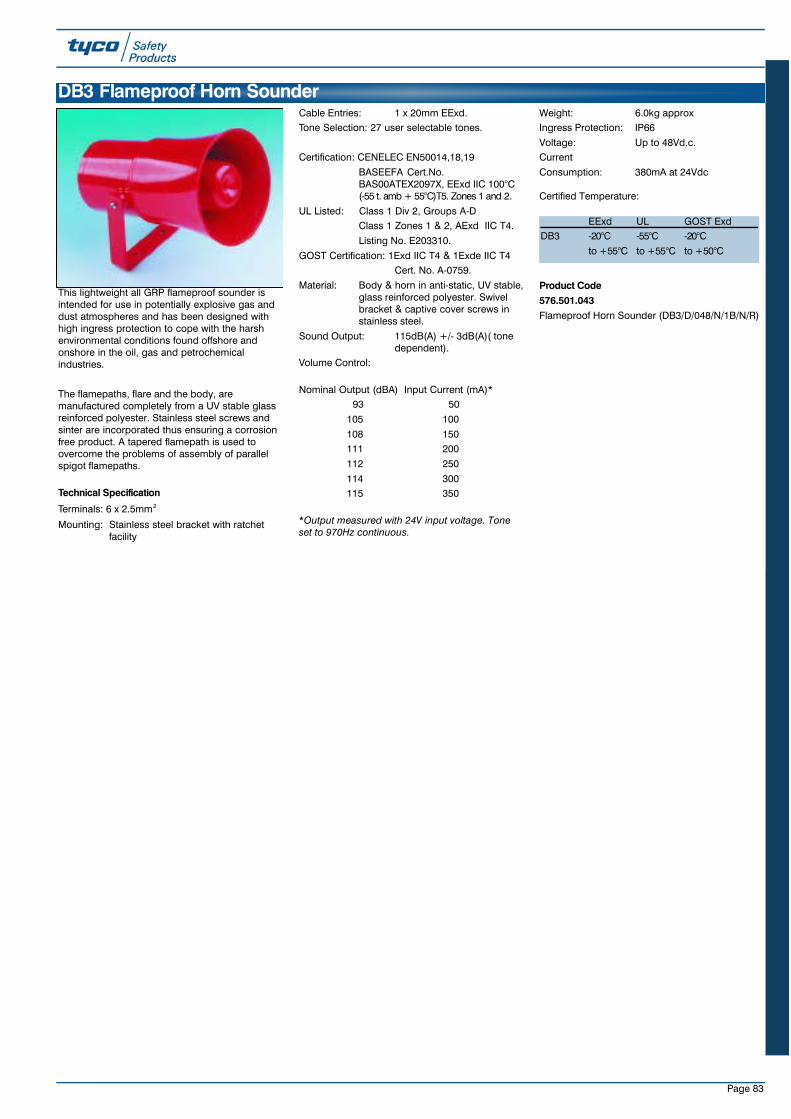
Page 83
This lightweight all GRP flameproof sounder isintended for use in potentially explosive gas anddust atmospheres and has been designed withhigh ingress protection to cope with the harshenvironmental conditions found offshore andonshore in the oil, gas and petrochemicalindustries.
The flamepaths, flare and the body, aremanufactured completely from a UV stable glassreinforced polyester. Stainless steel screws andsinter are incorporated thus ensuring a corrosionfree product. A tapered flamepath is used toovercome the problems of assembly of parallelspigot flamepaths.
Technical Specification
Terminals: 6 x 2.5mm2
Mounting: Stainless steel bracket with ratchet facility
Cable Entries: 1 x 20mm EExd.Tone Selection: 27 user selectable tones.
Certification: CENELEC EN50014,18,19
BASEEFA Cert.No. BAS00ATEX2097X, EExd IIC 100°C (-55 t. amb + 55°C)T5. Zones 1 and 2.
UL Listed: Class 1 Div 2, Groups A-DClass 1 Zones 1 & 2, AExd IIC T4.
Listing No. E203310.
GOST Certification: 1Exd IIC T4 & 1Exde IIC T4Cert. No. A-0759.
Material: Body & horn in anti-static, UV stable,glass reinforced polyester. Swivel bracket & captive cover screws in stainless steel.
Sound Output: 115dB(A) +/- 3dB(A)( tone dependent).
Volume Control:
Nominal Output (dBA) Input Current (mA)*93 50
105 100
108 150111 200
112 250
114 300115 350
*Output measured with 24V input voltage. Toneset to 970Hz continuous.
Weight: 6.0kg approxIngress Protection: IP66
Voltage: Up to 48Vd.c.Current
Consumption: 380mA at 24Vdc
Certified Temperature:
Product Code576.501.043Flameproof Horn Sounder (DB3/D/048/N/1B/N/R)
DB3 Flameproof Horn Sounder
EExd UL GOST ExdDB3 -20°C - 5 5 ° C -20°C
to +55°C to +55°C to +50°C
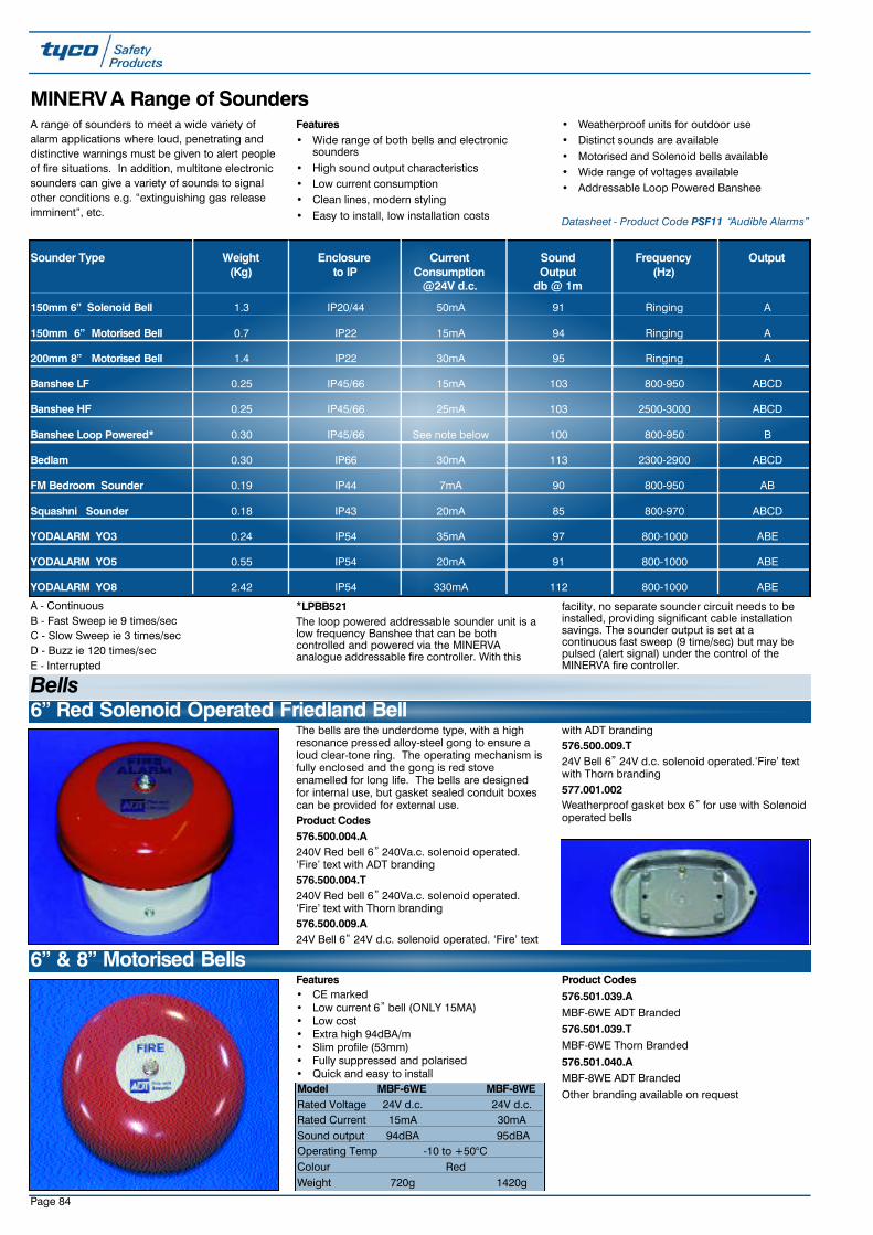
Page 84
The bells are the underdome type, with a highresonance pressed alloy-steel gong to ensure aloud clear-tone ring. The operating mechanism isfully enclosed and the gong is red stoveenamelled for long life. The bells are designedfor internal use, but gasket sealed conduit boxescan be provided for external use. Product Codes576.500.004.A240V Red bell 6” 240Va.c. solenoid operated.‘Fire’ text with ADT branding576.500.004.T240V Red bell 6” 240Va.c. solenoid operated.‘Fire’ text with Thorn branding576.500.009.A24V Bell 6” 24V d.c. solenoid operated. ‘Fire’ text
with ADT branding576.500.009.T24V Bell 6” 24V d.c. solenoid operated.‘Fire’ textwith Thorn branding577.001.002Weatherproof gasket box 6” for use with Solenoidoperated bells
6” Red Solenoid Operated Friedland Bell
MINERV A Range of SoundersA range of sounders to meet a wide variety ofalarm applications where loud, penetrating anddistinctive warnings must be given to alert peopleof fire situations. In addition, multitone electronicsounders can give a variety of sounds to signalother conditions e.g. “extinguishing gas releaseimminent”, etc.
Features• Wide range of both bells and electronic
sounders• High sound output characteristics• Low current consumption• Clean lines, modern styling• Easy to install, low installation costs
• Weatherproof units for outdoor use • Distinct sounds are available• Motorised and Solenoid bells available• Wide range of voltages available • Addressable Loop Powered Banshee
Datasheet - Product Code PSF11 “Audible Alarms”
Sounder Type Weight Enclosure Current Sound Frequency Output(Kg) to IP Consumption Output (Hz)
@24V d.c. db @ 1m
150mm 6” Solenoid Bell 1.3 IP20/44 50mA 91 Ringing A
150mm 6” Motorised Bell 0.7 IP22 15mA 94 Ringing A
200mm 8” Motorised Bell 1.4 IP22 30mA 95 Ringing A
Banshee LF 0.25 IP45/66 15mA 103 800-950 ABCD
Banshee HF 0.25 IP45/66 25mA 103 2500-3000 ABCD
Banshee Loop Powered* 0.30 IP45/66 See note below 100 800-950 B
Bedlam 0.30 IP66 30mA 113 2300-2900 ABCD
FM Bedroom Sounder 0.19 IP44 7mA 90 800-950 AB
Squashni Sounder 0.18 IP43 20mA 85 800-970 ABCD
YODALARM YO3 0.24 IP54 35mA 97 800-1000 ABE
YODALARM YO5 0.55 IP54 20mA 91 800-1000 ABE
YODALARM YO8 2.42 IP54 330mA 112 800-1000 ABE
A - ContinuousB - Fast Sweep ie 9 times/secC - Slow Sweep ie 3 times/secD - Buzz ie 120 times/secE - Interrupted
*LPBB521The loop powered addressable sounder unit is alow frequency Banshee that can be bothcontrolled and powered via the MINERVAanalogue addressable fire controller. With this
facility, no separate sounder circuit needs to beinstalled, providing significant cable installationsavings. The sounder output is set at acontinuous fast sweep (9 time/sec) but may bepulsed (alert signal) under the control of theMINERVA fire controller.
Features• CE marked• Low current 6” bell (ONLY 15MA)• Low cost • Extra high 94dBA/m• Slim profile (53mm)• Fully suppressed and polarised• Quick and easy to install
Product Codes576.501.039.AMBF-6WE ADT Branded576.501.039.TMBF-6WE Thorn Branded
576.501.040.AMBF-8WE ADT Branded
Other branding available on request
6” & 8” Motorised Bells
Model MBF-6WE MBF-8WERated Voltage 24V d.c. 24V d.c. Rated Current 15mA 30mASound output 94dBA 95dBAOperating Temp -10 to +50°CColour RedWeight 720g 1420g
Bells

Page 85
The standard Besson Wafer sounder is suppliedin white with a blank cover included. Thespecification is as follows:
Input voltage: 24V d.c. (+/-25%)Sound Output: 60dBA/90dBA at 1m typical (pot.Adjustable) offering the same sound formats asthe Banshee sounder range. It can therefore beused in conjunction with the Banshee sounderson the same site.
Technical SpecificationCurrent: 4mA to 15mATemperature Range: -40°C to + 70°C
Dimensions: Dia 103mm, Height 22mm (excluding coverplate)
Product Code576.501.038Besson wafer sounder and blank cover in white
The LPBB521 Line powered AddressableSounder is designed to be driven from a LoopPowered MINERVA Analogue Addressablecontroller via the addressable loop. The sounder
is low frequency [800-950hz]. The Sounderoutput is set to Fast Sweep, but may be pulsedunder the control of the MINERVA.
An ultra low profile alarm sounder for fire andsecurity applications utilising all of the bestfeatures of the traditional Banshee plus anadditional volume control fitted as standard. Thelow profile unit has been designed tocomplement new building interiors and isavailable in red or white.
Features• Ultra Low Profile
• Volume Control• Side and Rear cable entry• Optional Deep base• Loop in out terminalsSound Options: Buzz: Very fast sweep at approx 120Hz
Fast Sweep: 800Hz-950Hz, sweeping 9 /SecSlow sweep: 800Hz-950Hz, sweeping 3/Sec
Continuous: 850Hz
Banshee/Bedlam
Meeting the requirements for BS5839 part 1, theBedroom Sounder range is well suited to hotelsand residential environments where aesthetics isa prime concern. Matching the sound output ofthe Banshee range of sounders so therefore theycan be mixed on a site.
Features• Low current consumption 7mA• Dual sound options selected via a jumper
switch: ‘Continuous’ and ‘Fast Sweep’ 90dB
• Can be both Flush and Surface mounted• Robust terminal connectors to accommodate
up to 2.5mm2 conductorsProduct Codes576.501.032.AFlush Mount Sounder ADT Branded
576.501.032.TFlush Mount Sounder Thorn Branded
Flush Mount Bedroom Sounder
Product Code Branded Colour Power Freq dB Alarm Current Weatherproof576.501.004.A ADT Red 24V 800-950Hz 107 15mA No IP44576.501.008.A ADT Red 24V 2.5-3KHz 105 25mA No IP44576.501.033.A ADT White 24V 800-950Hz 107 15mA No IP44576.501.024.A ADT Red 24V 800-950Hz 107 15mA Yes IP66576.501.015.A ADT Red 24V 2.5-3KHz 117 30mA Yes IP66576.501.004.T Thorn Red 24V 800-950Hz 107 15mA No IP44576.501.008.T Thorn Red 24V 2.5-3KHz 105 25mA No IP44576.501.033.T Thorn White 24V 800-950Hz 107 15mA No IP44576.501.024.T Thorn Red 24V 800-950Hz 107 15mA Yes IP66576.501.015.T Thorn Red 24V 2.5-3KHz 117 30mA Yes IP66Sound levels are quoted on E-SPL Effective Sound Pressure Level @1 Metre which is the output in atypical room setting. 117dB models are known as Bedlam sounders
The combined mounting bracket for the BessonBanshee and Xenon Beacon allows quick andneat installation of combined sounders andbeacons. The bracket allows the followingelectronic sounders to be mounted with the rangeof 1W Xenon Beacons:
• Besson Banshee• Besson Bedlam• Loop powered MINERVA Besson Banshee • MINERVA FIRECRYER voice enhanced
sounderThe bracket can be used with any of the 24Vd.c1W Xenon beacons in red, clear, amber or blue(Part no.'s 540.001.030/031/032 & 033)
Product Codes576.501.041Banshee/Xenon bracket
576.501.042Banshee IP66 backbox for use with loop poweredbanshees and FIRECRYERS
577.001.006Flush mounting bracket for use with low profilebanshees - white576.501.011Banshee/Bedlam weatherproof mains adaptorpack 240Va.c. to 24Vd.c. use on any 24Vd.c.Banshee or Bedlam
Accessories
Line Powered Banshee
Besson Wafer Sounder
Banshee
Weatherproof Banshee
Bedlam
Banshee/Xenon Bracket
Banshee Flush Mount Bracket
Besson Wafer Sounder
Flush Mount Sounder
Electronic Sounders
Product Code Branded Colour Power Freq dB Alarm Current Weatherproof577.001.026.A ADT Red Loop LF 96 17mA No IP44577.001.029.A ADT White Loop LF 96 17mA No IP44577.001.026.T Thorn Red Loop LF 96 17mA No IP44577.001.029.T Thorn White Loop LF 96 17mA No IP44577.001.026.Y Tyco Red Loop LF 96 17mA No IP44577.001.029.Y Tyco White Loop LF 96 17mA No IP44
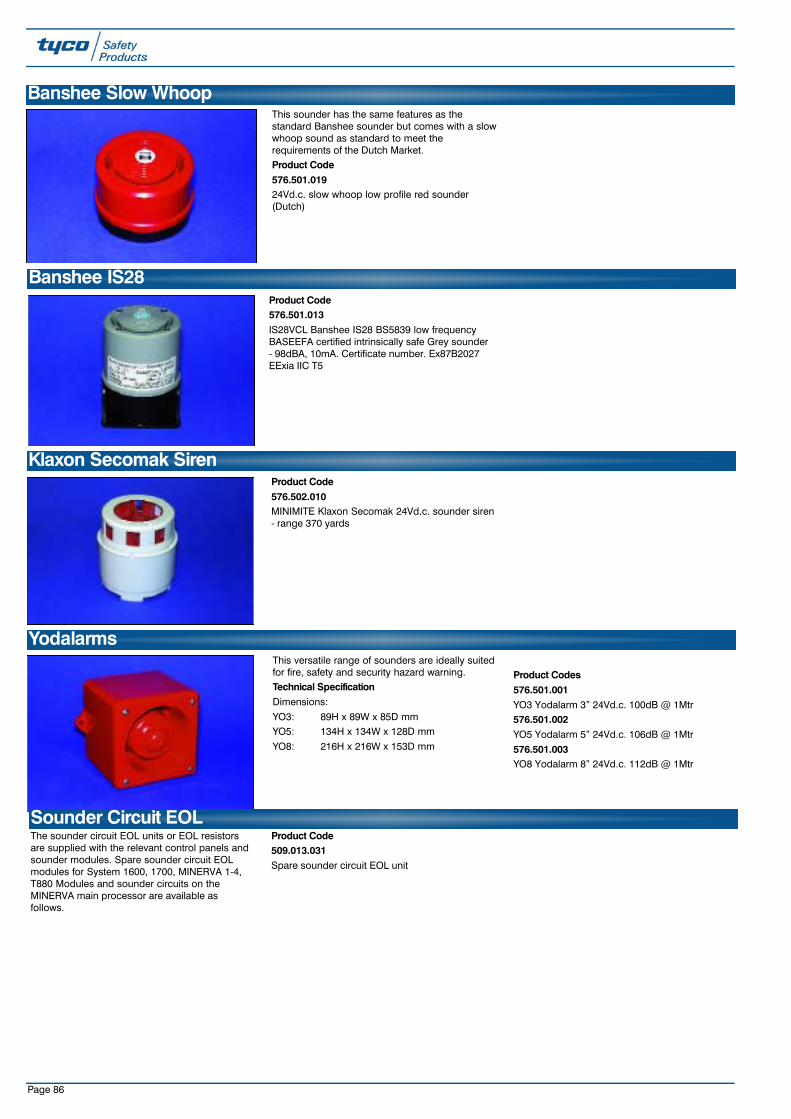
Page 86
This versatile range of sounders are ideally suitedfor fire, safety and security hazard warning.Technical SpecificationDimensions:
YO3: 89H x 89W x 85D mmYO5: 134H x 134W x 128D mm
YO8: 216H x 216W x 153D mm
Product Codes576.501.001YO3 Yodalarm 3” 24Vd.c. 100dB @ 1Mtr576.501.002YO5 Yodalarm 5” 24Vd.c. 106dB @ 1Mtr
576.501.003YO8 Yodalarm 8” 24Vd.c. 112dB @ 1Mtr
Yodalarms
Product Code 576.501.013IS28VCL Banshee IS28 BS5839 low frequencyBASEEFA certified intrinsically safe Grey sounder- 98dBA, 10mA. Certificate number. Ex87B2027EExia IIC T5
Banshee IS28
Product Code576.502.010MINIMITE Klaxon Secomak 24Vd.c. sounder siren- range 370 yards
Klaxon Secomak Siren
This sounder has the same features as thestandard Banshee sounder but comes with a slowwhoop sound as standard to meet therequirements of the Dutch Market.Product Code576.501.01924Vd.c. slow whoop low profile red sounder(Dutch)
Banshee Slow Whoop
The sounder circuit EOL units or EOL resistorsare supplied with the relevant control panels andsounder modules. Spare sounder circuit EOLmodules for System 1600, 1700, MINERVA 1-4,T880 Modules and sounder circuits on theMINERVA main processor are available asfollows.
Product Code509.013.031Spare sounder circuit EOL unit
Sounder Circuit EOL
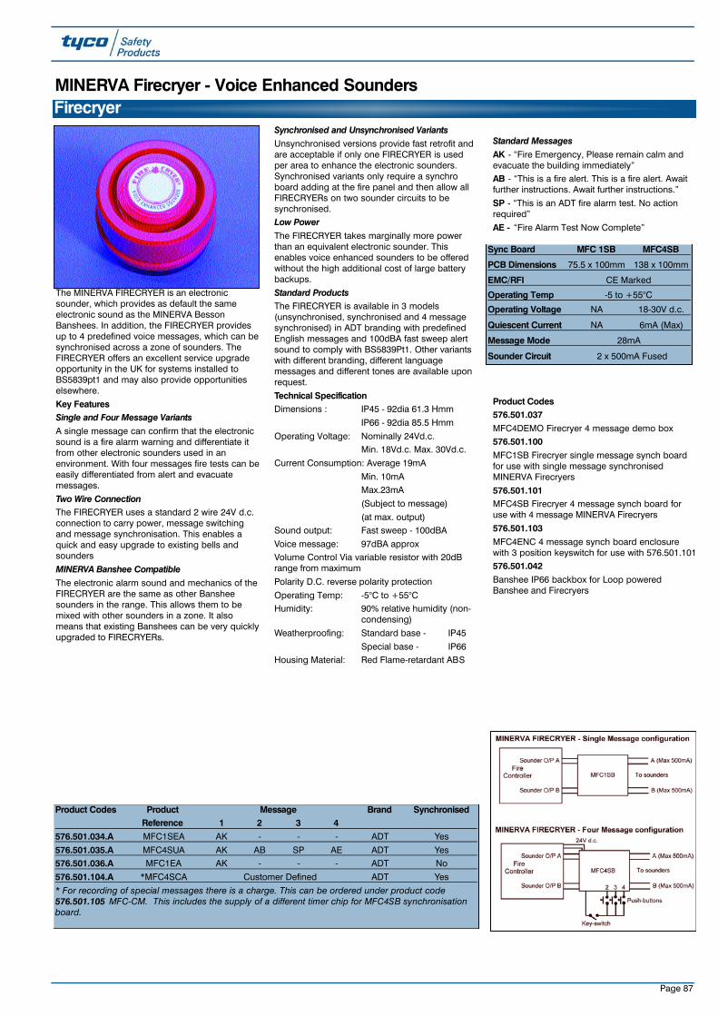
Page 87
The MINERVA FIRECRYER is an electronicsounder, which provides as default the sameelectronic sound as the MINERVA BessonBanshees. In addition, the FIRECRYER providesup to 4 predefined voice messages, which can besynchronised across a zone of sounders. TheFIRECRYER offers an excellent service upgradeopportunity in the UK for systems installed toBS5839pt1 and may also provide opportunitieselsewhere.
Key FeaturesSingle and Four Message VariantsA single message can confirm that the electronicsound is a fire alarm warning and differentiate itfrom other electronic sounders used in anenvironment. With four messages fire tests can beeasily differentiated from alert and evacuatemessages.
Two Wire ConnectionThe FIRECRYER uses a standard 2 wire 24V d.c.connection to carry power, message switchingand message synchronisation. This enables aquick and easy upgrade to existing bells andsounders
MINERVA Banshee CompatibleThe electronic alarm sound and mechanics of theFIRECRYER are the same as other Bansheesounders in the range. This allows them to bemixed with other sounders in a zone. It alsomeans that existing Banshees can be very quicklyupgraded to FIRECRYERs.
Synchronised and Unsynchronised VariantsUnsynchronised versions provide fast retrofit andare acceptable if only one FIRECRYER is usedper area to enhance the electronic sounders.Synchronised variants only require a synchroboard adding at the fire panel and then allow allFIRECRYERs on two sounder circuits to besynchronised.Low PowerThe FIRECRYER takes marginally more powerthan an equivalent electronic sounder. Thisenables voice enhanced sounders to be offeredwithout the high additional cost of large batterybackups.
Standard ProductsThe FIRECRYER is available in 3 models(unsynchronised, synchronised and 4 messagesynchronised) in ADT branding with predefinedEnglish messages and 100dBA fast sweep alertsound to comply with BS5839Pt1. Other variantswith different branding, different languagemessages and different tones are available uponrequest.
Technical SpecificationDimensions : IP45 - 92dia 61.3 Hmm
IP66 - 92dia 85.5 Hmm
Operating Voltage: Nominally 24Vd.c. Min. 18Vd.c. Max. 30Vd.c.
Current Consumption: Average 19mA
Min. 10mA Max.23mA
(Subject to message)
(at max. output)Sound output: Fast sweep - 100dBA
Voice message: 97dBA approxVolume Control Via variable resistor with 20dBrange from maximum
Polarity D.C. reverse polarity protection
Operating Temp: -5°C to +55°CHumidity: 90% relative humidity (non-
condensing)
Weatherproofing: Standard base - IP45
Special base - IP66Housing Material: Red Flame-retardant ABS
Standard MessagesAK - “Fire Emergency, Please remain calm andevacuate the building immediately”AB - “This is a fire alert. This is a fire alert. Awaitfurther instructions. Await further instructions.”
SP - “This is an ADT fire alarm test. No actionrequired”
AE - “Fire Alarm Test Now Complete”
Product Codes576.501.037MFC4DEMO Firecryer 4 message demo box576.501.100MFC1SB Firecryer single message synch boardfor use with single message synchronisedMINERVA Firecryers
576.501.101MFC4SB Firecryer 4 message synch board foruse with 4 message MINERVA Firecryers
576.501.103MFC4ENC 4 message synch board enclosurewith 3 position keyswitch for use with 576.501.101576.501.042Banshee IP66 backbox for Loop poweredBanshee and Firecryers
FirecryerMINERVA Firecryer - Voice Enhanced Sounders
Product Codes Product Message Brand SynchronisedReference 1 2 3 4
576.501.034.A MFC1SEA AK - - - ADT Yes
576.501.035.A MFC4SUA AK AB SP AE ADT Yes576.501.036.A MFC1EA AK - - - ADT No
576.501.104.A *MFC4SCA Customer Defined ADT Yes
* For recording of special messages there is a charge. This can be ordered under product code576.501.105 MFC-CM. This includes the supply of a different timer chip for MFC4SB synchronisationboard.
Sync Board MFC 1SB MFC4SB
PCB Dimensions 75.5 x 100mm 138 x 100mm
EMC/RFI CE Marked
Operating Temp -5 to +55°C
Operating Voltage NA 18-30V d.c.
Quiescent Current NA 6mA (Max)
Message Mode 28mA
Sounder Circuit 2 x 500mA Fused

These certified beacons have been designed foruse in potentially explosive gas and dustatmospheres and harsh environmentalconditions. The glass reinforced polyesterenclosures are suitable for use offshore oronshore, where light weight combined withcorrosion resistance is required.
The beacon housing ismanufactured completely from aU.V. stable, glass reinforcedpolyester. Stainless steel screwsand mounting bracket areincorporated ensuring a totallycorrosion free product.
Product Code540.001.039Flameproof Xenon Beacon(XB11B02406RNBNNNR)
Page 88
This high quality range of Xenon beacons aretested to IP 65 making them ideal for the moststringent applications.
Each beacon incorporates a low profile Frestrallens designed to give maximum light output.
The mounting base is available to mount both thebeacon and a sounder.Features• Available in 1, 2, 3 and 5 watts• Protected to I.P. 65• Attractive low profile design• Optional bracket for mounting both Beacon and. Banshee SounderProduct Codes540.001.030Low profile clear 24Vd.c. 1 watt
540.001.031Low profile blue 24Vd.c. 1 watt
540.001.032Low profile amber 24Vd.c. 1 watt
540.001.033Low profile red 24Vd.c. 1 watt20-112Low profile 2 watt Red
20-113Low profile 5 watt Red
20-120Low profile 3 watt Red
Xenon Beacons - 24V Including Surface Mount Adaptor
Lamp Buzzer units may be used for local alarmswhen high level audible warnings may not beappropriate. Available in flush and surface mountversions to fit standard single backboxesDimensions: 90H x 90W x 40D mm
Product Codes540.001.012Lamp (red)/buzzer unit flush mounting MK2including single gang backbox. Labelled ‘Fire’
540.001.013Lamp (red)/buzzer unit surface mounting MK2.Labelled ‘Fire’
Single Gang Lamp/Buzzer UnitsVisual Indicators
Technical Specification
Voltage Power Output Alarm Current Flash Rate Rating Temp. Range Dimensions (mm)V d.c. Watt(s) mA Height Diameter24 1 42 60/min IP65 -30 to +70°C 51 7524 2 84 60/min IP65 -30 to +70°C 51 7524 3 126 60/min IP65 -30 to +70°C 51 7524 5 210 60/min IP65 -30 to +70°C 75 90
XB11 Flameproof Xenon Beacon
Technical Specification
Certification: BASEEFA EExd IIB 100 °C (-55 t. amb +55°C)T5.85 °C (-55 t.amb + 40°C)T6.
Cert. No. 99 ATEX 2195X.CENELEC EN50014 and EN50018
Material: Body: - Glass reinforced polyesterLens: - Glass.Cover Screws + Backstrap: - Stainless steel 316.
Finish: Red
Voltage 24Vd.c.
Tube Energy(Joules) 5Peak Current Consumption (mA) 320
EffectiveIntensity (Cd) 29Peak Intensity (Cd) 22213
Power Consumption(Watts) 8Note: The Cd figures are for a clear lens @ “ 1Hz flash rate. For red lensmultiple by 0.15
Weight: 2.5KgCertified Temperature: EExd -55°C to + 55°C (T5)
-55°C to + 40°C (T6)Ingress Protection: IP66Terminals: 6 x 2.5mm2
Entries: 2 x 20mm ISO EExd.
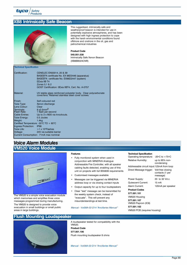
Page 89
VM520 Voice Module
The VM520 is a simple voice evacuation modulewhich memorises and amplifies three voicemessages programmed during manufacturing. The VM520 is designed to provide voiceevacuation in small buildings or small publicareas in large buildings.
Features
• Fully monitored system when used inconjunction with MINERVA AnalogueAddressable Fire Controller, with all speakercabling faults detected, enabling use of thisunit on projects with full BS5839 requirements
• Customised messages available
• Messages can be triggered via MINERVAaddress loop or via closing contact inputs
• Output capacity for up to four loudspeakers
• Clear “test” message can be transmitted forthe weekly system check, instead of“evacuate”. This will prevent anymisunderstandings at test time.
Manual - Vol08A-02-D14 “Ancillaries Manual”
Technical SpecificationOperating temperature: -20oC to +70oC
Relative Humidity: up to 95% non-condensing
Addressable circuit input:125mA from loopDirect Message trigger: Volt free closing
contacts (1 per message)
Power Supply: 20 to 32 Vd.c.
Quiescent Current: 15 mA Alarm Current: 120mA per speaker
Product Codes577.001.101VM520 Housing577.001.107VM520 Peprom (IC6)
577.001.102VM520 PCB (requires housing)
A loudspeaker tested for compatibility with theVM520.Product Code 577.001.106Flush mounting loudspeaker 8 ohms
Manual - Vol08A-02-D14 “Ancillaries Manual”
Flush Mounting Loudspeaker
Voice Alarm Modules
This ruggedised, intrinsically safe andweatherproof beacon is intended for use inpotentially explosive atmospheres, and has beendesigned with high ingress protection to copewith the harsh environmental conditions foundoffshore and onshore in the oil, gas andpetrochemical industries
Product Code540.001.038Intrinsically Safe Xenon Beacon(XB8BB024CNR)
XB8 Intrinsically Safe Beacon
Technical Specification
Certification: CENELEC EN50014, 20 & 39BASEEFA certificate No. EX 96D2446 (apparatus)BASEEFA certificate No. EX96D2447 (system)EExia IIB T4Zones 0,1 & 2GOST Certification: 0Exia IIBT4, Cert. No. A-0757
Material: UV stable glass reinforced polyester body. Clear polycarbonate cover/lens. Retained stainless steel cover screws.
Finish: Self coloured redTube Type: Xenon dischargeLens Colour: ClearTerminals: 8 x2.5mm2Flash Rate: 1 flash per secondCable Entries: Up to 3 x M20 via knockouts.Tube Energy: 0.5 JoulesWeight: 1.4kgCertified Temperature: -55°C TO + 60°CIngress Protection: IP66Tube Life: >1 x 10⁶FlashesVoltage: 24V via suitable barrierCurrent Consumption: 71mA max nominal
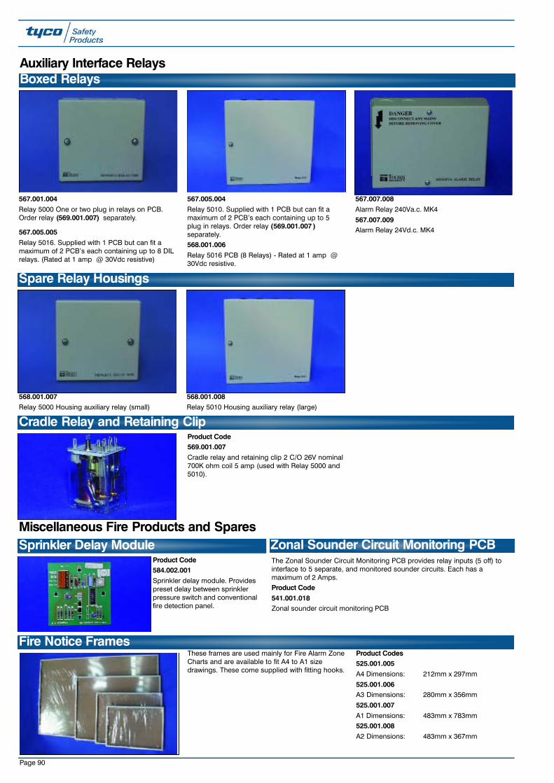
Page 90
Auxiliary Interface RelaysBoxed Relays
567.005.004Relay 5010. Supplied with 1 PCB but can fit amaximum of 2 PCB’s each containing up to 5plug in relays. Order relay (569.001.007 )separately.568.001.006Relay 5016 PCB (8 Relays) - Rated at 1 amp @30Vdc resistive.
567.001.004Relay 5000 One or two plug in relays on PCB.Order relay (569.001.007) separately.
567.007.008Alarm Relay 240Va.c. MK4
567.007.009Alarm Relay 24Vd.c. MK4
568.001.007Relay 5000 Housing auxiliary relay (small)
Spare Relay Housings
Product Code569.001.007Cradle relay and retaining clip 2 C/O 26V nominal700K ohm coil 5 amp (used with Relay 5000 and5010).
Cradle Relay and Retaining Clip
568.001.008Relay 5010 Housing auxiliary relay (large)
Product Code584.002.001Sprinkler delay module. Providespreset delay between sprinklerpressure switch and conventionalfire detection panel.
Sprinkler Delay ModuleMiscellaneous Fire Products and Spares
These frames are used mainly for Fire Alarm ZoneCharts and are available to fit A4 to A1 sizedrawings. These come supplied with fitting hooks.
Product Codes525.001.005A4 Dimensions: 212mm x 297mm
525.001.006A3 Dimensions: 280mm x 356mm
525.001.007A1 Dimensions: 483mm x 783mm525.001.008A2 Dimensions: 483mm x 367mm
Fire Notice Frames
567.005.005Relay 5016. Supplied with 1 PCB but can fit amaximum of 2 PCB’s each containing up to 8 DILrelays. (Rated at 1 amp @ 30Vdc resistive)
The Zonal Sounder Circuit Monitoring PCB provides relay inputs (5 off) tointerface to 5 separate, and monitored sounder circuits. Each has amaximum of 2 Amps.Product Code541.001.018Zonal sounder circuit monitoring PCB
Zonal Sounder Circuit Monitoring PCB

Page 91
No. of Cores x Cross Section (n x mm 2) Copper Content (Kg/Km) Total Weight (Kg/Km) Outer Diameter (approx. mm) Calorific Potential (KWh/m)2 x 1.0 19 75 7.4 0.162 x 1.5 29 97 8.2 0.182 x 2.5 48 141 9.6 0.244 x 1.0 39 114 8.6 0.234 x 1.5 58 149 9.6 0.27
DÄTWYLER Lifeline cable is suitable for firealarms and emergency lighting where BS6387and BS7629 standards are acceptable and meetsthe installation and performance requirements of:
• BS5839 Pt.1 for use in fire alarms• BS5266 for use with emergency lighting• BS4066 ‘Tests on electrical cable under fire
conditions’• IEC331 fire resistanceLifeline is LPCB approved to BS6387 CAT CWZand BASEC approved to BS7629.Lifeline is low smoke, zero halogen, has anintegral aluminium backed mylar tape screen with
tinned drain wire and requires no specialterminations, tools or ferrules for installation.
Full details of Lifeline cable can be found in theDÄTWYLER Lifeline datasheets on the Tyco SafetyProducts website (www.tycosafetyproducts -europe.com).DÄTWYLER offer a wide range of cable and safetycabling systems including complete safety cablesystems to DIN4102 part 12. All DÄTWYLERproducts are available at preferential prices toTyco companies via Tyco Safety Products. Formore information contact Rob Sutcliffe([email protected]).
The following DÄTWYLER Lifeline cables are heldin stock at Tyco Safety Products, Letchworthwarehouse, together with suitable P clips andglands. Cables are priced per metre but must beordered in units of 100 metre. P clips and glandsare priced each but must be ordered in packs.
Fire Resistant Cable
Product Codes Description - DÄTWYLER Lifeline cableNo. Cores Core Size Colour Clips
599.048.020 2 + earth 1 mm Red P34 R
599.048.022 2 + earth 1.5 mm Red P34 R599.048.023 2 + earth 1.5 mm White P34 W
599.048.024 2 + earth 2.5 mm Red P37 R
599.048.032 4 + earth 1 mm Red P37 R599.048.034 4 + earth 1.5 mm Red P40 R
599.048.035 4 + earth 1.5 mm White P40 W
Product Codes Description - DÄTWYLER Lifeline Fire Resistant P Clips & GlandsQty. per pack Reference Colour
599.048.001 50 P34 Red
599.048.002 50 P34 White599.048.003 50 P37 Red
599.048.005 50 P40 Red
599.048.006 50 P40 White599.048.007 50 P43 Red
599.048.009 10 NG1 Red
599.048.010 10 NG1 White
Technical Specification
Construction
Conductor: Bare copper, solid or stranded to BS 6360
Insulation: Special double layer insulation according to
BS 7655, E15
Inner Covering: High temperature resistant glass fibre tape
Screening: Al-Laminated tape with tinned copper drain wire, solid to BS 6360
Outer Sheath: Flame retardant polyolefin compound according to
BS 7655, LTS3
Technical Properties
Rated Voltage: 300/500V
Test Voltage: 2000V, 50Hz core/core
2000V, 50Hz core/screen
Operating Temp: -15oC to +90oC
Core Colours:
• 2 cores + earth: red, black
• 4 cores + earth:red,yellow,blue,black
Sheath Colour: Red or white
General Properties
• Zero Halogen, no corrosive gases - IEC 60754-2, BS 6425 part 1
• Reduced fire propagation - IEC 60332-3, BS 4066 part 3
• Minimum smoke emission - IEC 61034,BS 7622
• Insulation integrity - IEC 60331 (FE180), BS 6387 (cat. CWZ)
Approvals
• BASEC
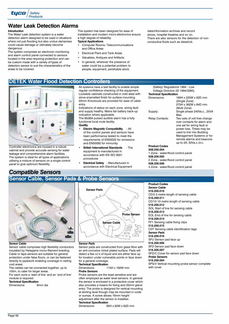
Page 92
Water Leak Detection Alarms
Controller electronics are housed in a robustcabinet and provide accurate sensing for waterleakage and comprehensive alarm facilities.The system is ideal for all types of applicationsutilising a mixture of sensors on a single controlpanel to give optimum flexibility.
All systems have a test facility to enable simpleregular confidence checking of the equipment.Lockable cabinets constructed in mild steel withstove enamelled finish for surface mounting.20mm Knockouts are provided for ease of cableentry.Indications of status on each zone, wiring faultand supply healthy. Mains fail battery back-upindication where applicable.The 85dBA pulsed audible alarm has a fullyfunctional local mute facility.Quality• Electro Magnetic Compatibility - All
of the control panels and sensors have been performance tested to meet the requirements of EN55022 for emissions and EN50092 for immunity
• British International Standards - The equipment is manufactured in accordance with EN ISO 9001 procedures
• Electrical Safety - Manufactured in accordance with Electrical Equipment
(Safety) Regulations 1994 - Low Voltage Directive (SI 1994/3260).
Technical SpecificationDimensions: 160H x 220W x 62D mm
(Single Zone)270H x 362W x 84D mm(Multi Zone)
Supply: Single phase 240Va.c., 25VAMax.
Relay Contacts: Two sets of volt free change over contacts for alarm and one set for wiring fault or power loss. These may be used to link into Building Management Systems or for remote alarms and beacons up to 2A, 50Va.c./d.c.
Product Codes508.200.0041 Zone - water/flood control panel508.200.0052 Zone - water/flood control panel508.200.0064 Zone - water/flood control panel
DETEK Water Flood Detection Controllers
Sensor CableSensor cable comprises high flexibility conductorsinsulated by Helagaine mono-filament braiding.Cable or tape sensors are suitable for generalprotection under false floors, or can be fasteneddirectly to pipework enabling coverage in ceilingvoid areas.The cables can be connected together, up to100m, to cater for larger areas.For each zone a ‘start of line’ and an ‘end of line’module is required.Technical SpecificationDimensions: 8mm dia
Sensor PadsSensor pads are constructed from glass fibre withan anti-corrosive nickel plated surface. Pads willdetect a few cc’s of liquid and are either face upfor location under vulnerable points or face downfor a general coverage.Technical SpecificationDimensions: 115H x 160W mmProbe SensorsProbe sensors are the least sensitive and areoften employed as water level sensors. In generalthe sensor is enclosed in a protective cover whichalso provides a means for fixing and 20mm glandentry. The probe is designed for vertical mountingat skirting level though may be mounted in voidsor sumps. A screw allows 16mm heightadjustment after the sensor is installed.Technical SpecificationDimensions: 85H x 62W x 62D mm
Product CodesSensor Cable516.200.010CD/5 5 metre length of sensing cable516.200.011CD/10 10 metre length of sensing cable516.200.012SOL Start of line for sensing cable516.200.013EOL End of line for sensing cable516.200.014FF1 Sensing cable fixing clips516.200.015CDT Sensing cable identification tagsSensor Pads516.200.016SFU Sensor pad face up516.200.006SFD Sensor pad face down516.200.007SFD/C Cover for sensor pad face downProbe Sensors516.200.004SPS/V Vertical mounting probe sensor completewith cover
Sensor Cable, Sensor Pads & Probe Sensors
IntroductionThe Water Leak detection system is a waterdetection alarm designed to be used in situationswhere not just flooding but also undue dampnesscould cause damage or ultimately becomedangerous.The system comprises an electronic monitoringand alarm control panel connected to sensorslocated in the area requiring protection and canbe custom made with a variety of types ofdetection sensor to suit the characteristics of theareas to be covered.
This system has been designed for ease ofinstallation and modern micro-electronics ensurea high degree of reliability.Typical Applications• Computer Rooms, Telecommunications
and Office Areas
• Electrical Plant and Tank Areas
• Valuables, Antiques and Artifacts
• In general, wherever the presence of water could be a potential problem to people, equipment, perishable stock,
data/information archives and record stores, hospital theatres and so on. There are also sensors for the detection of non-conductive fluids such as diesel/oil.
Compatible Sensors
Sensor Pads
Probe Sensor
Sensor Cable
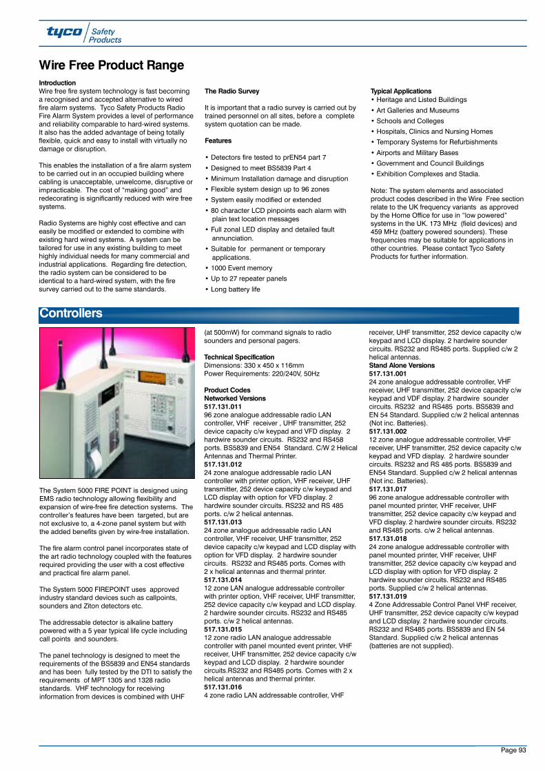
Page 93
Wire Free Product Range
Controllers
IntroductionWire free fire system technology is fast becominga recognised and accepted alternative to wiredfire alarm systems. Tyco Safety Products RadioFire Alarm System provides a level of performanceand reliability comparable to hard-wired systems.It also has the added advantage of being totallyflexible, quick and easy to install with virtually nodamage or disruption.
This enables the installation of a fire alarm systemto be carried out in an occupied building wherecabling is unacceptable, unwelcome, disruptive orimpracticable. The cost of “making good” andredecorating is significantly reduced with wire freesystems.
Radio Systems are highly cost effective and caneasily be modified or extended to combine withexisting hard wired systems. A system can betailored for use in any existing building to meethighly individual needs for many commercial andindustrial applications. Regarding fire detection,the radio system can be considered to beidentical to a hard-wired system, with the firesurvey carried out to the same standards.
The Radio Survey
It is important that a radio survey is carried out bytrained personnel on all sites, before a completesystem quotation can be made.
Features
• Detectors fire tested to prEN54 part 7
• Designed to meet BS5839 Part 4
• Minimum Installation damage and disruption
• Flexible system design up to 96 zones
• System easily modified or extended
• 80 character LCD pinpoints each alarm withplain text location messages
• Full zonal LED display and detailed faultannunciation.
• Suitable for permanent or temporaryapplications.
• 1000 Event memory
• Up to 27 repeater panels
• Long battery life
Typical Applications• Heritage and Listed Buildings
• Art Galleries and Museums
• Schools and Colleges
• Hospitals, Clinics and Nursing Homes
• Temporary Systems for Refurbishments
• Airports and Military Bases
• Government and Council Buildings
• Exhibition Complexes and Stadia.
Note: The system elements and associatedproduct codes described in the Wire Free sectionrelate to the UK frequency variants as approvedby the Home Office for use in “low powered”systems in the UK. 173 MHz (field devices) and459 MHz (battery powered sounders). Thesefrequencies may be suitable for applications inother countries. Please contact Tyco SafetyProducts for further information.
The System 5000 FIRE POINT is designed usingEMS radio technology allowing flexibility andexpansion of wire-free fire detection systems. Thecontroller’s features have been targeted, but arenot exclusive to, a 4-zone panel system but withthe added benefits given by wire-free installation.
The fire alarm control panel incorporates state ofthe art radio technology coupled with the featuresrequired providing the user with a cost effectiveand practical fire alarm panel.
The System 5000 FIREPOINT uses approvedindustry standard devices such as callpoints,sounders and Ziton detectors etc.
The addressable detector is alkaline batterypowered with a 5 year typical life cycle includingcall points and sounders.
The panel technology is designed to meet therequirements of the BS5839 and EN54 standardsand has been fully tested by the DTI to satisfy therequirements of MPT 1305 and 1328 radiostandards. VHF technology for receivinginformation from devices is combined with UHF
(at 500mW) for command signals to radiosounders and personal pagers.
Technical Specification Dimensions: 330 x 450 x 116mmPower Requirements: 220/240V, 50Hz
Product CodesNetworked Versions517.131.01196 zone analogue addressable radio LANcontroller, VHF receiver , UHF transmitter, 252device capacity c/w keypad and VFD display. 2hardwire sounder circuits. RS232 and RS458ports. BS5839 and EN54 Standard. C/W 2 HelicalAntennas and Thermal Printer.517.131.01224 zone analogue addressable radio LANcontroller with printer option, VHF receiver, UHFtransmitter, 252 device capacity c/w keypad andLCD display with option for VFD display. 2hardwire sounder circuits. RS232 and RS 485ports. c/w 2 helical antennas.517.131.01324 zone analogue addressable radio LANcontroller, VHF receiver, UHF transmitter, 252device capacity c/w keypad and LCD display withoption for VFD display. 2 hardwire soundercircuits. RS232 and RS485 ports. Comes with 2 x helical antennas and thermal printer. 517.131.01412 zone LAN analogue addressable controllerwith printer option, VHF receiver, UHF transmitter,252 device capacity c/w keypad and LCD display.2 hardwire sounder circuits. RS232 and RS485ports. c/w 2 helical antennas.517.131.01512 zone radio LAN analogue addressablecontroller with panel mounted event printer, VHFreceiver, UHF transmitter, 252 device capacity c/wkeypad and LCD display. 2 hardwire soundercircuits.RS232 and RS485 ports. Comes with 2 xhelical antennas and thermal printer.517.131.0164 zone radio LAN addressable controller, VHF
receiver, UHF transmitter, 252 device capacity c/wkeypad and LCD display. 2 hardwire soundercircuits. RS232 and RS485 ports. Supplied c/w 2helical antennas. Stand Alone Versions517.131.00124 zone analogue addressable controller, VHFreceiver, UHF transmitter, 252 device capacity c/wkeypad and VDF display. 2 hardwire soundercircuits. RS232 and RS485 ports. BS5839 andEN 54 Standard. Supplied c/w 2 helical antennas(Not inc. Batteries).517.131.00212 zone analogue addressable controller, VHFreceiver, UHF transmitter, 252 device capacity c/wkeypad and VFD display. 2 hardwire soundercircuits. RS232 and RS 485 ports. BS5839 andEN54 Standard. Supplied c/w 2 helical antennas(Not inc. Batteries). 517.131.01796 zone analogue addressable controller withpanel mounted printer, VHF receiver, UHFtransmitter, 252 device capacity c/w keypad andVFD display. 2 hardwire sounder circuits. RS232and RS485 ports. c/w 2 helical antennas.517.131.01824 zone analogue addressable controller withpanel mounted printer, VHF receiver, UHFtransmitter, 252 device capacity c/w keypad andLCD display with option for VFD display. 2hardwire sounder circuits. RS232 and RS485ports. Supplied c/w 2 helical antennas.517.131.0194 Zone Addressable Control Panel VHF receiver,UHF transmitter, 252 device capacity c/w keypadand LCD display. 2 hardwire sounder circuits.RS232 and RS485 ports. BS5839 and EN 54Standard. Supplied c/w 2 helical antennas(batteries are not supplied).
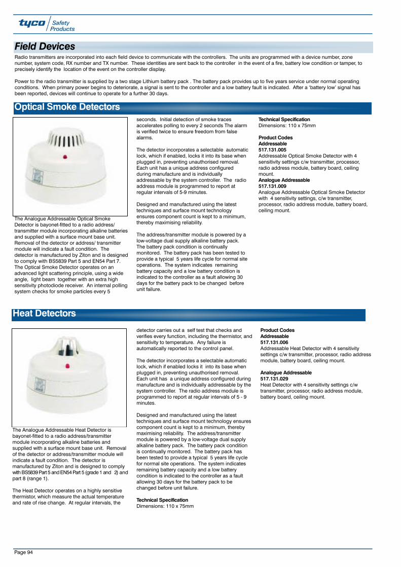
Page 94
Heat Detectors
The Analogue Addressable Heat Detector isbayonet-fitted to a radio address/transmittermodule incorporating alkaline batteries andsupplied with a surface mount base unit. Removalof the detector or address/transmitter module willindicate a fault condition. The detector ismanufactured by Ziton and is designed to complywith BS5839 Part 5 and EN54 Part 5 (grade 1 and 2) andpart 8 (range 1).
The Heat Detector operates on a highly sensitivethermistor, which measure the actual temperatureand rate of rise change. At regular intervals, the
detector carries out a self test that checks andverifies every function, including the thermistor, andsensitivity to temperature. Any failure isautomatically reported to the control panel.
The detector incorporates a selectable automaticlock, which if enabled locks it into its base whenplugged in, preventing unauthorised removal.Each unit has a unique address configured duringmanufacture and is individually addressable by thesystem controller. The radio address module isprogrammed to report at regular intervals of 5 - 9minutes.
Designed and manufactured using the latesttechniques and surface mount technology ensurescomponent count is kept to a minimum, therebymaximising reliability. The address/transmittermodule is powered by a low-voltage dual supplyalkaline battery pack. The battery pack conditionis continually monitored. The battery pack hasbeen tested to provide a typical 5 years life cyclefor normal site operations. The system indicatesremaining battery capacity and a low batterycondition is indicated to the controller as a faultallowing 30 days for the battery pack to bechanged before unit failure.
Technical SpecificationDimensions: 110 x 75mm
Product Codes Addressable517.131.006Addressable Heat Detector with 4 sensitivitysettings c/w transmitter, processor, radio addressmodule, battery board, ceiling mount.
Analogue Addressable517.131.029Heat Detector with 4 sensitivity settings c/wtransmitter, processor, radio address module,battery board, ceiling mount.
Optical Smoke Detectors
The Analogue Addressable Optical SmokeDetector is bayonet-fitted to a radio address/transmitter module incorporating alkaline batteriesand supplied with a surface mount base unit.Removal of the detector or address/ transmittermodule will indicate a fault condition. Thedetector is manufactured by Ziton and is designedto comply with BS5839 Part 5 and EN54 Part 7.The Optical Smoke Detector operates on anadvanced light scattering principle, using a wideangle, light beam together with an extra highsensitivity photodiode receiver. An internal pollingsystem checks for smoke particles every 5
seconds. Initial detection of smoke tracesaccelerates polling to every 2 seconds The alarmis verified twice to ensure freedom from falsealarms.
The detector incorporates a selectable automaticlock, which if enabled, locks it into its base whenplugged in, preventing unauthorised removal.Each unit has a unique address configuredduring manufacture and is individuallyaddressable by the system controller. The radioaddress module is programmed to report atregular intervals of 5-9 minutes.
Designed and manufactured using the latesttechniques and surface mount technologyensures component count is kept to a minimum,thereby maximising reliability.
The address/transmitter module is powered by alow-voltage dual supply alkaline battery pack.The battery pack condition is continuallymonitored. The battery pack has been tested toprovide a typical 5 years life cycle for normal siteoperations. The system indicates remainingbattery capacity and a low battery condition isindicated to the controller as a fault allowing 30days for the battery pack to be changed beforeunit failure.
Technical SpecificationDimensions: 110 x 75mm
Product Codes Addressable517.131.005Addressable Optical Smoke Detector with 4sensitivity settings c/w transmitter, processor,radio address module, battery board, ceilingmount.Analogue Addressable517.131.009Analogue Addressable Optical Smoke Detectorwith 4 sensitivity settings, c/w transmitter,processor, radio address module, battery board,ceiling mount.
Radio transmitters are incorporated into each field device to communicate with the controllers. The units are programmed with a device number, zonenumber, system code, RX number and TX number. These identities are sent back to the controller in the event of a fire, battery low condition or tamper, toprecisely identify the location of the event on the controller display.
Power to the radio transmitter is supplied by a two stage Lithium battery pack . The battery pack provides up to five years service under normal operatingconditions. When primary power begins to deteriorate, a signal is sent to the controller and a low battery fault is indicated. After a ‘battery low’ signal hasbeen reported, devices will continue to operate for a further 30 days.
Field Devices
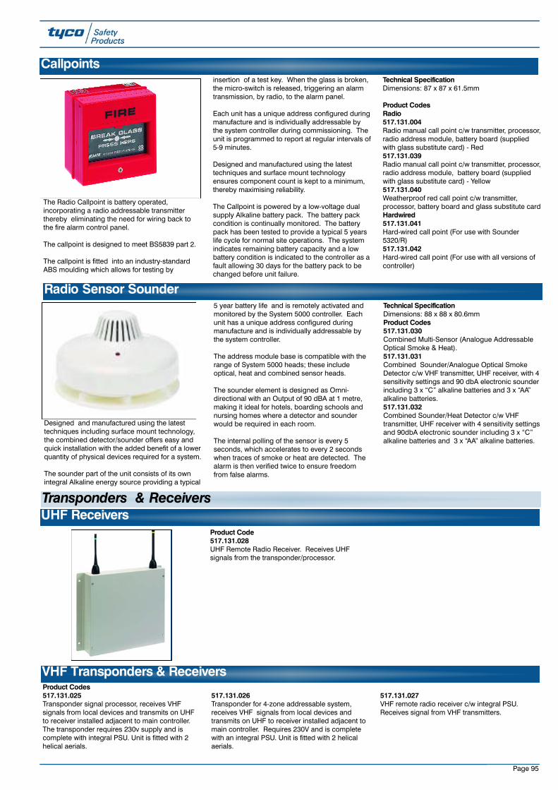
Product Codes 517.131.025Transponder signal processor, receives VHFsignals from local devices and transmits on UHFto receiver installed adjacent to main controller.The transponder requires 230v supply and iscomplete with integral PSU. Unit is fitted with 2helical aerials.
517.131.026Transponder for 4-zone addressable system,receives VHF signals from local devices andtransmits on UHF to receiver installed adjacent tomain controller. Requires 230V and is completewith an integral PSU. Unit is fitted with 2 helicalaerials.
517.131.027VHF remote radio receiver c/w integral PSU.Receives signal from VHF transmitters.
VHF Transponders & Receivers
Page 95
The Radio Callpoint is battery operated,incorporating a radio addressable transmitterthereby eliminating the need for wiring back tothe fire alarm control panel.
The callpoint is designed to meet BS5839 part 2.
The callpoint is fitted into an industry-standardABS moulding which allows for testing by
insertion of a test key. When the glass is broken,the micro-switch is released, triggering an alarmtransmission, by radio, to the alarm panel.
Each unit has a unique address configured duringmanufacture and is individually addressable bythe system controller during commissioning. Theunit is programmed to report at regular intervals of5-9 minutes.
Designed and manufactured using the latesttechniques and surface mount technologyensures component count is kept to a minimum,thereby maximising reliability.
The Callpoint is powered by a low-voltage dualsupply Alkaline battery pack. The battery packcondition is continually monitored. The batterypack has been tested to provide a typical 5 yearslife cycle for normal site operations. The systemindicates remaining battery capacity and a lowbattery condition is indicated to the controller as afault allowing 30 days for the battery pack to bechanged before unit failure.
Technical SpecificationDimensions: 87 x 87 x 61.5mm
Product CodesRadio517.131.004Radio manual call point c/w transmitter, processor,radio address module, battery board (suppliedwith glass substitute card) - Red517.131.039Radio manual call point c/w transmitter, processor,radio address module, battery board (suppliedwith glass substitute card) - Yellow517.131.040Weatherproof red call point c/w transmitter,processor, battery board and glass substitute cardHardwired517.131.041Hard-wired call point (For use with Sounder5320/R)517.131.042Hard-wired call point (For use with all versions ofcontroller)
Callpoints
Designed and manufactured using the latesttechniques including surface mount technology,the combined detector/sounder offers easy andquick installation with the added benefit of a lowerquantity of physical devices required for a system.
The sounder part of the unit consists of its ownintegral Alkaline energy source providing a typical
5 year battery life and is remotely activated andmonitored by the System 5000 controller. Eachunit has a unique address configured duringmanufacture and is individually addressable bythe system controller.
The address module base is compatible with therange of System 5000 heads; these includeoptical, heat and combined sensor heads.
The sounder element is designed as Omni-directional with an Output of 90 dBA at 1 metre,making it ideal for hotels, boarding schools andnursing homes where a detector and sounderwould be required in each room.
The internal polling of the sensor is every 5seconds, which accelerates to every 2 secondswhen traces of smoke or heat are detected. Thealarm is then verified twice to ensure freedomfrom false alarms.
Technical SpecificationDimensions: 88 x 88 x 80.6mmProduct Codes 517.131.030Combined Multi-Sensor (Analogue AddressableOptical Smoke & Heat).517.131.031Combined Sounder/Analogue Optical SmokeDetector c/w VHF transmitter, UHF receiver, with 4sensitivity settings and 90 dbA electronic sounderincluding 3 x “C” alkaline batteries and 3 x “AA”alkaline batteries.517.131.032Combined Sounder/Heat Detector c/w VHFtransmitter, UHF receiver with 4 sensitivity settingsand 90dbA electronic sounder including 3 x “C”alkaline batteries and 3 x “AA” alkaline batteries.
Radio Sensor Sounder
UHF ReceiversProduct Code 517.131.028UHF Remote Radio Receiver. Receives UHFsignals from the transponder/processor.
Transponders & Receivers
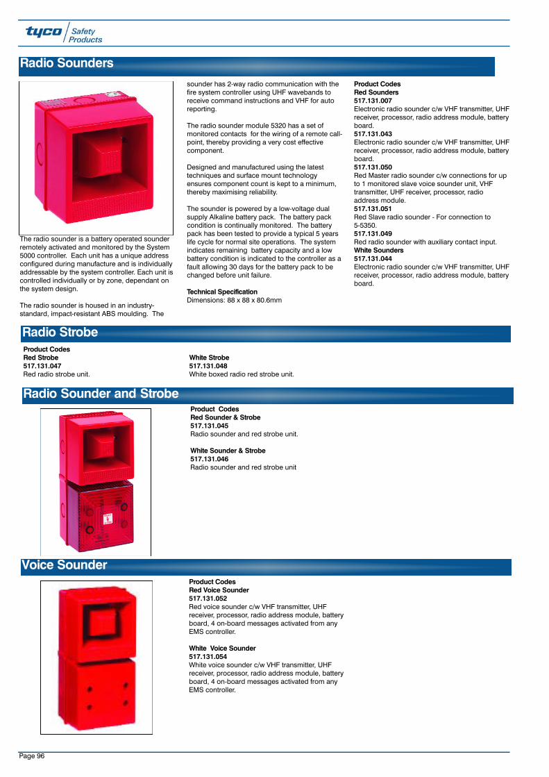
Page 96
Product CodesRed Strobe517.131.047Red radio strobe unit.
White Strobe517.131.048White boxed radio red strobe unit.
Radio Strobe
Product CodesRed Sounder & Strobe517.131.045Radio sounder and red strobe unit.
White Sounder & Strobe517.131.046Radio sounder and red strobe unit
Radio Sounder and Strobe
The radio sounder is a battery operated sounderremotely activated and monitored by the System5000 controller. Each unit has a unique addressconfigured during manufacture and is individuallyaddressable by the system controller. Each unit iscontrolled individually or by zone, dependant onthe system design.
The radio sounder is housed in an industry-standard, impact-resistant ABS moulding. The
sounder has 2-way radio communication with thefire system controller using UHF wavebands toreceive command instructions and VHF for autoreporting.
The radio sounder module 5320 has a set ofmonitored contacts for the wiring of a remote call-point, thereby providing a very cost effectivecomponent.
Designed and manufactured using the latesttechniques and surface mount technologyensures component count is kept to a minimum,thereby maximising reliability.
The sounder is powered by a low-voltage dualsupply Alkaline battery pack. The battery packcondition is continually monitored. The batterypack has been tested to provide a typical 5 yearslife cycle for normal site operations. The systemindicates remaining battery capacity and a lowbattery condition is indicated to the controller as afault allowing 30 days for the battery pack to bechanged before unit failure.
Technical SpecificationDimensions: 88 x 88 x 80.6mm
Product CodesRed Sounders517.131.007Electronic radio sounder c/w VHF transmitter, UHFreceiver, processor, radio address module, batteryboard.517.131.043Electronic radio sounder c/w VHF transmitter, UHFreceiver, processor, radio address module, batteryboard.517.131.050Red Master radio sounder c/w connections for upto 1 monitored slave voice sounder unit, VHFtransmitter, UHF receiver, processor, radioaddress module. 517.131.051Red Slave radio sounder - For connection to 5-5350.517.131.049Red radio sounder with auxiliary contact input.White Sounders517.131.044Electronic radio sounder c/w VHF transmitter, UHFreceiver, processor, radio address module, batteryboard.
Radio Sounders
Product CodesRed Voice Sounder517.131.052Red voice sounder c/w VHF transmitter, UHFreceiver, processor, radio address module, batteryboard, 4 on-board messages activated from anyEMS controller.
White Voice Sounder517.131.054White voice sounder c/w VHF transmitter, UHFreceiver, processor, radio address module, batteryboard, 4 on-board messages activated from anyEMS controller.
Voice Sounder

Page 97
Product CodesRed Voice Sounder& Strobe517.131.053Voice sounder/strobe c/w VHF transmitter, UHFreceiver, processor, radio address module, batteryboard, 4 on-board messages activated from anyEMS controller.517.131.056Weatherproof voice sounder c/w VHF transmitter,UHF receiver, processor , radio address module,
battery board, 4 on-board messages activatedfrom any EMS controller. 517.131.057Master Voice Unit c/w connections for up to 1monitored slave voice sounder unit. VHFtransmitter, UHF receiver, processor, radioaddress module, battery board, 4 on-boardmessages activated from any EMS controller.
517.131.058Slave Voice Unit for connection to 5-5381 with it’sown monitored battery supply.White Voice Sounder & Strobe517.131.055Voice sounder/strobe c/w VHF transmitter, UHFreceiver, processor, radio address module, batteryboard, 4 on-board messages activated from anyEMS controller.
Voice Sounder and Strobe
Product Codes517.131.022UHF high gain aerial.517.131.023UHF helical antenna c/w BNC connector.
517.131.024UHF high gain directional aerial c/w wallmounting bracket, extension pole and 10m lowloss RG213 cable.
UHF AntennaAerials & Ancillaries
Product Codes 517.131.003VHF aerial c/w 20m RG213 coax cable. 517.131.020VHF dipole half wave antenna c/w 10MRG58 cable and bracket.
517.131.021VHF helical aerial c/w BNC connector.
VHF Antenna
Product Codes517.131.008Interface input/output unit (used for output signalsto activate other equipment) c/w transmitter,processor, radio address module, battery board. 517.131.059Addressable Interface input/output unit (used foroutput signals to activate other equipment) c/wtransmitter, processor, radio address module,battery board.
517.131.060Interface input/output unit (used for outputsignals to activate other equipment) c/wtransmitter, processor, radio address module,battery board, external antenna and housed inmetal case. 517.131.061Plant I/O shunt unit - for plant isolation during testmode (4 zone).
Interface Modules
Product Codes517.131.033Analogue addressable optical smoke sensor(Replacement only).517.131.034Heat sensor (Replacement only).517.131.035Addressable transmitter/processor/battery.
517.131.036Addressable optical smoke sensor (Replacementonly).517.131.037Addressable Heat sensor (Replacement only).517.131.038Addressable transmitter/processor/battery.
Service Spares
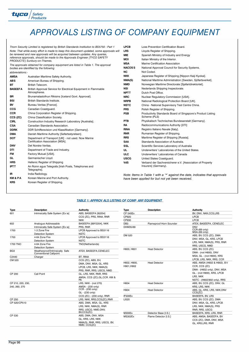
Page 98
APPROVALS LISTING OF COMPANY EQUIPMENT
Thorn Security Limited is registered by British Standards Institution to BS5750 : Part 1Note: That while every effort is made to keep this document updated, some approvals willbe renewed and new approvals will be acquired between updates. Any queries,reference approvals, should be made to the Approvals Engineer [TYCO SAFETYPRODUCTS} Sunbury-on-Thames.
The approvals obtained for company equipment are listed in Table 1. The approvalbodies are identified by the following
abbreviations:-
AMSA Australian Maritime Safety Authority.
ABS American Bureau of Shipping.
BT British Telecom.
BASEEFA British Approval Service for Electrical Equipment in Flammable Atmospheres.
BR Brunamalastofnun Rikisins [Iceland Govt. Approval].
BSI British Standards Institute.
BV Bureau Veritas [France].
CCG Canadian Coastguard.
CCR China Corporation Register of Shipping.
CCS (ZC) China Classification Society.
CIRL Construction Industry Research Laboratory [Australia].
CSA Canadian Standards Association.
DDRK DDR Schiffsrevision und Klassifikation [Germany].
DMA Danish Maritime Authority [Søfartsstyrelsen].
DOT Department of Transport [UK] - not used. Now Marine Certification Association [MSA].
DNV Det Norske Veritas.
DTI Department of Trade and Industry.
FM Factory Mutual [USA].
GL Germanischer Lloyd.
HRS Hellenic Register of Shipping
IPTT An Roinn agus Telegrafa [Irish Posts, Telephones and Telegraphs].
IR India Radiology.
KM & PA Korean Marine and Port Authority.
KRS Korean Register of Shipping.
LPCB Loss Prevention Certification Board.
LRS Lloyds Register of Shipping.
MIE Spanish Ministry of Industry and Energy
MOI Italian Ministry of the Interior.
MSA Marine Certification Association
NACOS S National Approval Council for Security Systems.
NC Not Coded.
NKK Japanese Register of Shipping.[Nippon Kaiji Kyokai].
NMA(S) National Maritime Administration [Sweden, Sjöfartsverket].
NMD Norwegian Maritime Directorate [Sjøfartdirektortet].
NSI Nederlands Shipping Inspectorate.
NPTT Dutch Post Office.
NRC Nuclear Regulatory Commission [USA].
NRPB National Radiological Protection Board [UK].
NSTC China - National Supervisory Test Centre China.
PRS Polish Register of Shipping.
PSB Productivity Standards Board of Singapore’s Product Listing Scheme (PLS)
PTB Physikalisch Technisches Bundesanstalt [Germany].
RA Radiocommunications Authority [DTI]
RINA Registro Italiano Navale [Italy].
RNR Rumanian Register of Shipping.
RRS Maritime Register of Shipping [Russia].
SAA Standards Association of Australia.
SSL Scientific Services Laboratory of Australia
UL Underwriters’ Laboratories of the United States.
ULC Underwriters’ Laboratories of Canada
USCG United States Coastguard.
VdS Verband der Sachversicherer e.V. [Association of Property Insurers] (Germany).
Note: Items in Table 1 with a ‘*’ against the date, indicates that approvalshave been applied for but not yet been received.
Type Description Authority601 Intrinsically Safe System [Ex ia] ABS, BASEEFA [82254]
CCS (ZC), PRS, RINA, RNRNKK
602 Analogue Addressable BASEEFA [89Y2204], NKKIntrinsically Safe System [Ex ia] PRS, RNR
1700 1-3 Zone Fire LPCB Approved to BS3116Detection System NSTC
1700 4-64 Zone Fire LPCB Approved to BS3116Detection System NSTC
1700 TNO 4-64 Zone Fire TNO(Netherlands)Detection System
BG3 Weatherproof/Intrinsically Safe ATEX, BASEEFA,CENELECConventional Callpoint
C2440 Charger BT, RINACM 520 CCS (ZC), ABS, BV,
DMA, DNV, MSA, GL, KRSLPCB, LRS, NKK, NMA(S)PRS, RNR, RRS, USCG, NMD
CP 200 Call Point GL, LRS, NKK, RNR, RRSAMSA, CCS (ZC),GL,CCR. KM & PA
CP 210, 220, 230, LRS, NKK - (not 270)240, 260, 270 AMSA - (230 only)
CCR - (230 only)GL - (230 only)CCS (ZC) - (230 only), RNR
CP 250 LRS, NKK, RRS,CCS(ZC),RNRCP 520/CP510 ABS, DMA, MSA, GL, KRS
LRS, NKK, NMA(S), RNRRRS, USCG, NMD,DNV,BV,CCS(ZC)
CP 530 ABS, DMA, DNV, MSAGL, KRS, LRS, NKKNMA(S), RNR, RRS, USCG, BV,NMD, CCS(ZC)
Type Description AuthorityCP 540Ex BV, DNV, NKK,CCS,LRSCP920 LPCBCP930 LPCBDB3 Flameproof Horn Sounder ATEX, BASEEFA, CENELECDHM35/69 DNV
CCR-(69 only)MSA-(69 only)
DM 520 ABS, BV, CCS (ZC), DMADNV, MSA, GL, KRS, LPCBLRS, NKK, NMA(S), PRS, RNRRRS, USCG, NMD
H600, H601 Heat Detector ABS, BV, CCS (ZC)DMA - (not H600), DNVMSA, GL - (not H600), KRSLPCB, LRS, NKK, RRS, CCR
H602, H900, Heat Detector ABS, AMSA (H602 & H902), B VH901,H902 CCR, CCS (ZC)
DMA - (H602 only), DNV, MSAGL - (not H900), KRS, LPCBLRS, NKKNSTC - (H602/902 only), RRS
H604 Heat Detector ABS, BV, CCS (ZC), DNV, GLKRS, LRS, NKK
H904 Heat Detector ABS, GL, KRS, LRS, NKK,DNVCCS(ZC)
IF500Ex BASEEFA, BV, LRSLI520 ABS, BV, CCS (ZC), DMA
DNV, MSA, GL, KRS, LPCBLRS, NKK, NMA(S), PRSRNR, RRS, USCG
M300Ex Detector Base [I.S.] BASEEFA, KRS, LRS, RNRMS302Ex Flame Detector [I.S.] ABS, AMSA, BASEEFA, BV
CCS (ZC), DMA, DNV, MSA GL, KRS,LRS, RNR
TABLE 1: APPROV ALS LISTING OF COMP ANY EQUIPMENT

Page 99
Type Description AuthorityM500Ex Intrinsically Safe Detector Base ABS, LPCB, DNV, KRS
LRS, RNR, USCGMD501Ex Intrinsically Safe Analogue ABS, BASEEFA, BV, CCS (ZC)
Addressable Heat Sensor DNV, GL, KRS, LRS, NKKPRS, RNR, RRS, USCG
MF501Ex Analogue Addressable Ion ABS, BASEEFA, BV, CCS (ZC)Chamber Sensor [I.S.] DNV, GL, KRS, LRS, NKK
NRPB, PRS, RNR, RRS, USCGMR501Ex Analogue Addressable ABS, BASEEFA, BV, CCS (ZC)
Optical Sensor [I.S.] DNV, GL, KRS, LRS, NKK, PRS RNR, RRS, USCG
MR501TEx Analogue Addressable High BASEEFAPerformance Optical Sensor [I.S.]
MS502Ex Analogue Addressable ABS, AMSA, BASEEFA, BVInfra Red Sensor [I.S.] CCG, CCS (ZC), DNV, NMA(S)
KRSMD601 Gr. 1 Rate of Rise Heat Detector LPCB, MIE,LRS,ABS,DNV,KRS,MSAMD601EX Conventional Rate of Rise Heat ABS, DNV, (LRS,KRS,BV,NKK
Detector Pending)
MD611 Gr. 2 Fixed Temp. Heat Detector LPCB, MIEMD611EX Conventional Fixed Temperature ABS, DNV, (LRS,KRS,BV,NKK
Heat Detector Pending)
612H Heat detector 135 ° F Fixed/ R-of-R UL, ULC622H Heat detector 135 ° F Fixed UL, ULC632H Heat detector 200 ° F Fixed UL, ULCMD613 Gr. 1 Rate of Rise Heat Detector VdSMD623 Gr. 2 Static Heat Detector VdSMDU601EX Enhanced Carbon Monoxide ABS, DNV, (LRS,KRS,BV,NKK
Fire & Heat Detector Pending)MF601EX Conventional Ion Chamber ABS, DNV (LRS,KRS,BV,NKK
Smoke Detector pending)MF601 Ion Chamber Detector NRPB, LPCB, NSTC, BV
MF601M Ion Chamber Detector ABS, BV, DNV, GL, KRSMSA, LRS, NKK, PRS, RRS
612I Ionisation Smoke Detector ULMF613 Ion Chamber Detector VdSMR601 Optical Smoke Detector LPCB, LRS, MIEMR601M Optical Smoke Detector ABS, BV, DNV, GL, KRS
MSA, NKK, PRSMR601TEX Conventional High Performance ABS, DNV, (LRS,KRS,BV,NKK
Optical Smoke Detector Pending)612P Photoelectronic Smoke Detector UL, ULC, FM MR613 Optical Smoke Detector VdSMR601T High Performance Optical Smoke LPCB, MIE
Detector612HP High Performance Optical Smoke NEDG, UL, ULC, FM
DetectorMR613T High Performance Optical Smoke VdS
DetectorMD901 Analogue Addressable Heat Sensor LPCB, NSTC,
MIE,LRS,ABS,DNV,KRS,MSA912H Heat Detector Head UL, ULC, FMMF901 Analogue Addressable Ion LPCB, NSTC,NRPB,RINA,RRS,
Chamber Detector USCG, BVMF901M Analogue Addressable Ion ABS, BV, DNV, GL, KRS, MSA
Chamber Detector LRS, NKK, PRS912I Ionisation Detector Head UL, ULC, FM MR901 Analogue Addressable Optical LPCB, LRS, MIE
Smoke SensorMR901M Analogue Addressable Optical ABS, BV, DNV, GL, KRS, MSA
Smoke Sensor NKK, PRS912P Photoelectronic Detector Head UL, ULC, FM MR901T Analogue Addressable High LPCB, NSTC, MIE
Performance Optical SensorMU601EX Conventional CarbonMonoxide ABS,DNV,(LRS,KRS,BV,NKK
Detector pending)912HP High Performance Photoelectronic UL, FM
Smoke Detector HeadMINERVA 8 PSB,LPCBMINERVA 16R LPCB, NSTCMINERVA 16E LPCB, NSTC, PSB,TNOMINERVA 80 LPCB, NSTC, PSB, TNOMINERVA 80R LPCB, NSTCMTL Intrinsically Safe Systems CSA, BASEEFA
EquipmentNT100 8 and 16 Zone Controllers ABS, BV, DNV, FAB, GL, LPCB
ANPI/BOSEC, LRSAB(Sweden)
NTR08/NTR16 Releasing Panels ANPI/BOSECPRECEPT Marine Fire Controller LRS,LPCBRM520 ABS, AMSA, BV, CCS (ZC)
DMA, DNV, MSA, GL, KRS LPCB, LRS, NKK, NMA(S)PRS, RRS, USCG
Type Description AuthorityRelay 5000 BTRelay 5010 BTS111, S112 IR Flame Detector ABS, BASEEFA [812333], BV
CCS (ZC), DMA, MSA, KRS LPCB, LRS, PRS, RRS, SAAVdS
S121 IR Flame Detector ABS, BASEEFA [812333], BVCCS (ZC), CSA, DMA, MSAKRS, LPCB, LRS, SAA, VdS
S122 IR Flame Detector ABS, BASEEFA [812333]BV, CCS (ZC), DMA, MSAKRS, LRS, SAA
S131 IR Flame Detector ABS, BASEEFA [812333], DNVMSA,PRS, LRS, NSTC, SAAVdS
S161 I.R. Flame Detector BASEEFA [87Y3550], DNVMSA, LPCB, LRS
S231f+ I.R. Flame Detector (Flameproof) DMA, BASEEFA [EX94C1388] LPCB,DNV, LRS, MSA, NSTC,KFEIC,SSL
S232f+ I.R. Flame Detector (Flameproof) DMA, BASEEFA [EX94C1388],FMS231i+ I.R. Flame Detector (I.S.) DMA, BASEEFA [EX94C2080]
LPCB, DNV, LRS, MSA,NSTC,KFEIC,SSL
S241f+ I.R. Flame Detector (Flameproof) DMA, BASEEFA [EX94C1388]LPCB, DNV,LRS,MSA, NSTC,KFEIC,SSL
S241i+ I.R. Flame Detector (I.S.) DMA, BASEEFA [EX94C2080] LPCB, DNV, LRS, MSA,NSTC,KFEIC,SSL
S251f+ I.R. Flame Detector (Flameproof) DMA, BASEEFA [EX94C1388]LPCB, DNV, LRS, MSA,NSTC,KFEIC,SSL
S252f+ I.R. Flame Detector (Flameproof) DMA, BASEEFA [EX94C1388]FM
S251i+ I.R. Flame Detector (I.S.) DMA, BASEEFA [EX94C2080],LRS,MSA
S261f+ I.R. Flame Detector (Flameproof) DMA, BASEEFA [EX94C1388]LPCB,DNV, LRS, MSA,NSTC,KFEIC,SSL
S262f+ I.R. Flame Detector (Flameproof) DMA, BASEEFA [EX94C1388]FM
SB520 Sounder Booster Module ABS, BV, CCS (ZC), DMAMSA, GL, KRS, LPCB, LRSNKK, NMA(S), PRS, RNRRRS, USCG, DNV
SM520 Sounder Module ABS, BV, CCS (ZC), DMAMSA, GL, KRS, LPCB, LRSNKK, NMA(S), PRS, RNRRRS, USCG, DNV
T1000 Marine Controllers ABS, BV, CCS, DNV, GL, NKKKRS, LRS, RINA, RRS, MSA
T110 I.R. Test Source BASEEFA [Ex84B2224]T210 I.R. Test Source BASEEFA [Ex84B2224]T882 4-Zone Fire Controller ABS, BV, CCS (ZC), CCR, DNV
MSA, GL, KRS, LRS, NKK, PRSRINA, RNR, RRS, CCG,NMD,DMA,DOT
T890 80-Zone Fire Controller ABS, AMSA, BV, CCS (ZC)[Minerva Marine] CCG, DNV, MSA, GL, KRS
LRS, NKK, NMA(S), PRS, RINARNR, RRS, USCG,DMA,NMD,DOT
T891 16-Zone Fire Controller ABS, BV, CCS (ZC), CCG[Minerva Marine] DMA, DNV, MSA, GL, KRS
NKK, NMA(S), PRS, RNR, RINARRS, USCG, LRS, NMD,DOT
ThornNet LPCBTLK530 LPCBWIRE FREEPRODUCT RANGE LPCB(Pending)XB8 Intrinsically Safe Beacon BASEEFA, CENELECXB11 Flameproof XenonBeacon BASEEFA, CENELEC, ATEX
APPROVALS LISTING OF COMPANY EQUIPMENT

Page 100
Standard AutoCAD SymbolsTyco Safety Products now has an IntraNet sitedevoted to users of AutoCAD Design Packages forelectronic and electrical systems.The site has been set up with a view to utilising acommon approach to AutoCAD output for drawingoffices using Tyco Safety Products products andsystems.Initially this site includes Standard Symbols for TycoMX Technology & MX-Graph, Fire, CCTV and Access
Products and also Diagrams for many Tyco SafetyProducts products supplied from the UK, this will beexpanded to include all Tyco Safety Productsproducts.Please encourage your CAD operators to visit thiswebsite. Even if you're business does not use allthese products many of the symbols, schematics anddrawings may be adapted quickly and easily for otherproducts.
If you require any further information on this or otheraspects of CAD development please contact thehelpdesk on +44 (0) 1932 743 327 or contact ourwebsite at www.tycosafetyproducts-europe.com.
Symbol NameFACPMTGX.dwg
ADDRESSABLE ACPMMODULE
Symbol NameFAM.dwg
CONVENTIONALASPIRATING MODULE
Symbol NameFAN.dwg
CONVENTIONALANALYSER
Symbol NameFASU.dwg
CONVENTIONALASPIRATING SAMPLINGUNIT
Symbol NameFBANTGX.dwgADDRESSABLEBANSHEE SOUNDER
(Variants available)
Symbol NameFBAR.dwgCONVENTIONAL FIREBARRIER
Symbol NameFBATT.dwgCONVENTIONALBATTERY UNIT
Symbol NameFBELLTGX.dwgADDRESSABLE BELL
Symbol NameFBI.dwgCONVENTIONAL BELLINTERFACE
Symbol NameFBRX.dwgCONVENTIONAL BEAMRECEIVER
Symbol NameFBTX.dwgCONVENTIONAL BEAMTRANSMITTER
Symbol NameFCHARGER.dwgCONVENTIONALCHARGER
Symbol NameFCMTGX.dwg
ADDRESSABLECONTACT MODULE
Symbol NameFCPSTGX.dwg
ADDRESSABLECALLPOINT
Symbol NameFCPTGX.dwg
ADDRESSABLECALLPOINT
Symbol NameFCPWPTGX.dwg
ADDRESSABLEWEATHERPROOFCALLPOINT
Symbol NameFDMTGX.dwgADDRESSABLEDETECTOR MODULE
Symbol NameFDRUTGX.dwgADDRESSABLE DOORRELEASE UNIT
Symbol NameFELIGHT.dwgCONVENTIONALEMERGENCY LIGHT
Symbol NameFEOL.dwgCONVENTIONAL ENDOF LINE UNIT
Symbol NameFEXIT.dwg
CONVENTIONALEMERGENCY LIGHT
Symbol NameFFDTGX.dwg
ADDRESSABLE FLAMEDETECTOR
Symbol NameFFLTGX.dwg
ADDRESSABLE XENONBEACON
Symbol NameFFTTGX.dwg
ADDRESSABLE FIXEDTEMPERATURE HEATDETECTOR
Symbol NameFHD.dwgCONVENTIONAL HEAVYDUTY RELAY
Symbol NameFHPTGX.dwgADDRESSABLE HIGHPERFORMANCEOPTICAL SMOKEDETECTOR
Symbol NameFICDP.dwgCONVENTIONALIONISATION DUCTPROBE
Symbol NameFICDPTGX.dwgADDRESSABLEIONISATION DUCTPROBE
Symbol NameFICTGX.dwgADDRESSABLE IONCHAMBER SMOKEDETECTOR
Symbol NameFICV.dwgCONVENTIONALIONISTATIONDETECTORFLOOR/CEILING VOID
Symbol NameFII.dwgCONVENTIONALINTRUDER INTERFACE
Symbol NameFIRFDTGX.dwgADDRESSABLE IRFLAME DETECTOR
Symbol NameFISH.dwg
CONVENTIONALINTRINSICALLY SAFEHOUSING
Symbol NameFJB.dwgCONVENTIONALJUNCTION BOX
Symbol NameFLBTGX.dwg
ADDRESSABLE LAMPBUZZER
Symbol NameFMEDCPTGX.dwg
ADDRESSABLE MEDCCALLPOINT
Symbol NameFMPIM.dwg
CONVENTIONAL MPIMMODULE
Symbol NameFNAU.dwgCONVENTIONALNETWORKATTACHMENT UNIT
Symbol NameFOMNI660.dwg
ADDRESSABLEOMNIGUARD 660DETECTOR
Symbol NameFOMNI860.dwg
ADDRESSABLEOMNIGUARD 860DETECTOR
Symbol NameFOVALVE.dwgCONVENTIONAL OILVALVE
Symbol NameFPAC1.dwgCONVENTIONALCABINET MOUNTEDSPEAKER
Symbol NameFPAC2.dwgCONVENTIONALCABINET MOUNTED BIDIRECTIONAL SPEAKER
Symbol NameFPAC3.dwgCONVENTIONALCABINET MOUNTED TRIDIRECTIONAL SPEAKER

Page 101
Symbol NameFPAC4.dwg
CONVENTIONALCEILING MOUNTEDSPEAKER
Symbol NameFPAC5.dwg
CONVENTIONAL HORN
Symbol NameFPANEL.dwg
CONVENTIONAL PANEL
Symbol NameFPM.dwg
CONVENTIONAL PLANTMODULE
Symbol NameFPODPTGX.dwgADDRESSABLE PHOTOOPTICAL DUCT PROBE
Symbol NameFPOTGX.dwgADDRESSABLEOPTICAL SMOKEDETECTOR
Symbol NameFPOV.dwgCONVENTIONAL PHOTOOPTICAL DETECTORFLOOR/CEILING VOID
Symbol NameFPROG.dwgCONVENTIONALPROGRAMMER
Symbol NameFPSU.dwgCONVENTIONALPOWER SUPPLY UNIT
Symbol NameFPUTGX.dwgADDRESSABLE PLANTINTERFACE MODULE
Symbol NameFREP.dwgCONVENTIONALREPEATER PANEL
Symbol NameFRI.dwgCONVENTIONALREMOTE INDICATOR
Symbol NameFRMTGX.dwg
ADDRESSABLE RELAYMODULE
Symbol NameFRORTGX.dwg
ADDRESSABLE RATEOF RISE HEATDETECTOR
Symbol NameFRSU.dwg
CONVENTIONALREFERENCE SAMPLINGUNIT
Symbol NameFRU.dwg
CONVENTIONAL RESETUNIT
Symbol NameFS100.dwgADDRESSABLE S100FLAME DETECTOR
Symbol NameFS200.dwgADDRESSABLE S200FLAME DETECTOR
Symbol NameFSB.dwgCONVENTIONALSOUNDER BOOSTERMODULE
Symbol NameFSCI.dwgCONVENTIONAL SHORTCIRCUIT ISOLATOR
Symbol NameFSDRTGX.dwg
ADDRESSABLESOUNDER
Symbol NameFSDRWTGX.dwg
ADDRESSABLEWEATHERPROOFSOUNDER
Symbol NameFSDTGX.dwg
ADDRESSABLE SMOKEDAMPER INTERFACEMODULE
Symbol NameFSI.dwg
CONVENTIONAL SHUNTINTERFACE
Symbol NameFSMTGX.dwg
ADDRESSABLESOUNDER MODULE
Symbol NameFSOUNDER.dwg
CONVENTIONALSOUNDER
Symbol NameFSPLY.dwg
CONVENTIONALPOWER SUPPLY UNIT
Symbol NameFSR.dwg
CONVENTIONAL SLAVERELAY
Symbol NameFSUTGX.dwgADDRESSABLE SHOPINTERFACE UNIT
Symbol NameFT525.dwgCONVENTIONALINDICATOR & MODESELECT UNIT
Symbol NameFT526.dwgCONVENTIONAL DELAYBUTTON
Symbol NameFT527.dwgCONVENTIONALELECTRICAL MANUALRELEASE UNIT
Symbol NameFT528.dwgCONVENTIONALMECHANICAL MANUALRELEASE UNIT
Symbol NameFT529.dwgCONVENTIONAL ABORTBUTTON
Symbol NameFTCH.dwgCONVENTIONALTERMINAL CHAMBER
Symbol NameFTM.dwgCONVENTIONAL TIMERMODULE
Symbol Name
FVESLC.dwgADDRESSABLE VESDALASER COMPACT
Symbol Name
FVESLP.dwgADDRESSABLE VESDADETECTOR
Symbol Name
FVESLS.dwgADDRESSABLE VESDASCANNER
Symbol Name
FVESRT.dwgADDRESSABLE VESDAOPTIONAL REMOTEDISPLAY
Symbol NameFVESSR.dwg
ADDRESSABLE VESDASUB RACK
Symbol NameFVMTGX.dwg
ADDRESSABLE VOICEMODULE
Symbol NameFXIOM.dwg
CONVENTIONAL XIOMMODULE

INDEX
Page 102
Stockcode Product Description Page10-115 SR2-T KAC Backbox With Two
Terminals 79171.392 Multiple tone sounder with adj.
Volume control - Deep base 8120-100 6 Inch 24v Dc Electronic Bell
Weatherproof - Wormald Branded White 81
20-101 6 Inch 24v Dc Electronic Bell - Wormald Branded Red 81
20-112 2W Xenon Beacon Low Profile Red 24v Dc 2watt 88
20-113 5W Xenon Beacon Low Profile Red 24v Dc 5watt 88
20-118 Combined Roshni Sounder / Strobe. Fixed to Tone 3Sweeping 800/970 Hz at 1 Hz 82
20-120 3W Xenon Beacon Low Profile Red 24v Dc 3watt 88
2500/021 CB200 1 ZONE CONVENTIONAL PANEL 23
2500/022 CB200 2 ZONE CONVENTIONAL PANEL 23
2500/032 C1437 4 way alarm extender board; CE requirement - PCB must be supplied c/w cabinets 23
2500/034 A1466 1 x double pole relay board (1A contacts); CE requirement - PCB must be supplied c/w cabinets 23
2500/045 PRESCIENT SPRINKLER PRE-ACTION PANEL EXTINGUISHING CONTROL PANEL 32
2500/048 Status indicator; maximum load - 3 per panel 32
2500/049 Status indicator complete with manual release and auto/manual keyswitch; maximum load - 3 per panel 32
2500/050 Status indicator complete with manual release and auto/manual keyswitch & timer hold; maximum load - 3 per panel 32
2500/051 Weatherproof 3 way status indicator; maximum load - 1 per panel 32
2500/052 Weatherproof 3 way status indicator with keyswitch; maximum load - 1 per panel 32
2500/053 Actuator Suppression Kit 322500/220 Control Equipment Ltd Enclosure
c/w 1A PSU & space for 4 x C1437 and 2 x A1466 & 6.2AH battery set 23
2500/221 Control Equipment Ltd Enclosure c/w 3A PSU & space for 2 x C1324 or 4 x C1437 boards 23
2500/222 Control Equipment Ltd Enclosure c/w 5A PSU & space for 2 x C1324 or 4 x C1437 boards 23
2500/507 Weight monitoring system complete (1 load cell and 1 unit) 32
2500/755 PRECEPT MARINE 2 ZONE 24V DC CONTROL PANEL 37
2500/756 PRECEPT MARINE 4 ZONE 24V DC CONTROL PANEL 37
2500/757 PRECEPT MARINE 8 ZONE 24V DC CONTROL PANEL 37
2500/758 PRECEPT MARINE 16 ZONE 24V DC CONTROL PANEL 37
2500/759 PRECEPT MARINE 32 ZONE 24V DC CONTROL PANEL 37
2500/774 PRECEPT MARINE 2 ZONE 230V CONTROL PANEL 37
2500/775 PRECEPT MARINE 4 ZONE 230V CONTROL PANEL 37
2500/776 PRECEPT MARINE 8 ZONE 230V CONTROL PANEL 37
2500/777 PRECEPT MARINE 16 ZONE 230V CONTROL PANEL 37
2500/778 PRECEPT MARINE 32 ZONE 230V CONTROL PANEL 37
2501/025 Manual Release Unit 322501/028 Weatherproof Manual Release
Unit (IP65) 323010 12v 2.1Ah Rechargable Battery 393071 12v 2.8Ah Rechargable Battery 393072 12v 7Ah Rechargable Battery 393085 12v 1.2Ah Rechargable Battery 393150 12v 65Ah Rechargable Battery
(Np65-12) 39
Stockcode Product Description Page40-103 DRU/24B Door Release Unit
24vdc With Keeper Plate 4040-104 Door Release Unit 240v Ac With
Keeper Plate 4040-105 Floor Mounting Brackets For
40-103/104 40508.013.016 T680M Power Changeover Unit 38508.013.030 T882M 4 Zone Conventional
Controller C/W PSU 36508.013.031 T882M 4 Zone Conventional
Controller W/O PSU 36508.014.011.A 1700 2 Aperture Housing With
ADT Branding 27508.014.011.T 1700 2 Aperture Housing In
Thorn Security Branding 27508.014.013.A 1700 3 Aperture Housing In
ADT Branding 27508.014.013.T 1700 3 Aperture Housing In
Thorn Security Branding 27508.014.015.A 1700 5 Aperture Housing In
ADT Branding 27508.014.015.T 1700 5 Aperture Housing In
Thorn Security Branding 27508.014.019 1700 Aperture Blanking Plate 27508.014.020 1700 Alarm PCB & Display 24508.014.021 1700 Alarm Repeater Display 26508.014.022 1700 16 Zone Repeater Display 26508.014.023 1700 4 Zone PCB & Display 25508.014.024 1700 8 Zone PCB & Display 25508.014.026 1700 Sector Sounder PCB 25508.014.027 1700 Sounder Extension PCB 25508.014.028 1700 Relay PCB 25508.014.029 1700 Multiplex Tx PCB 26508.014.030 1700 Multiplex Rx PCB 26508.014.031 1700 External Power Interface
PCB 24508.014.032 1700 1.5 Amp 240v PSU 24508.014.033 1700 3 Amp 240v PSU 24508.014.035 1700 Custom Legend Strips,Blank 27508.014.036 1700 1.5 Amp 115 V PSU 24508.014.037 1700 3 Amp 115v PSU 24508.014.038 1700 Installation Kit For 5
Aperture Housing 27508.014.039.A 1700 8 Aperture Housing - ADT
Branded 27508.014.039.T 1700 8 Aperture Housing - Thorn
Branded 27508.014.047 1700 Installation Kit For 3 Aperture
Housing 27508.014.048 1700 Coincidence Module PCB 27508.014.050 1700 Alarm Unit Display Dutch
TNO 24508.014.053 1700 Battery Clamp Kit For 10Ah
Batteries 27508.014.055 S1700 KEY System 1700 Spare
Key TOK001 Farnell Part Number149-964 24
508.014.056 1700 Extinguishing Cards 26508.020.006 Thorngraph 22" Touchscreen -
Liyama Touch Pro 510 Complete With 5 Year Warranty 3
508.020.007 Dell GX110 PC for use with ThornGraph or MxGraph depending on the software ordered - includes 250Mb Iomega internal zip drive With Windows NT 4, Service Pack, Preloaded and defined with default passwords 3
508.020.101 Software Package A For 1 Network Node 3
508.020.102 Software Package B For 2-5 Network Node 3
508.020.103 Software Package C For 6 Or More Network Nodes 3
508.020.104 Software Package D For Additional Graphics Nodes On The Same Thorn Net 3
508.022.001 NTR08-011-03 Conventional Extinguishing Release Fire Controller - Finnish 29
508.022.002 NTR08-011-05 Conventional Extinguishing Release Fire Controller - Swedish 29
508.022.003 NTR08-003-02 Conventional Extinguishing Release Fire Controller - U.K. 29
508.022.004 NTR08-004-02 Conventional Extinguishing Release Fire Controller - Belgian 29
Stockcode Product Description Page508.022.008 NT108-001-01 8 Zone Conventional
Fire Controller U.K. 28508.022.009 NT108-002-01 8 Zone Conventional
Fire Controller Belgian 28508.022.010 NT108-002-14 8 Zone Conventional
Fire Controller Dutch 28508.022.011 NTF08-009-08 8 Zone Conventional
Fire Controller Finnish C/W Firemans Interface 28
508.022.014 NTF08-009-11 8 Zone Conventional Fire Controller Danish C/W Firemans Interface 28
508.022.016 NT116-001-01 16 Zone Conventional Fire Controller U.K. 28
508.022.017 NT116-002-01 16 Zone Conventional Fire Controller Belgium 28
508.022.018 NT116-002-14 16 Zone Conventional Fire Controller Dutch 28
508.022.019 NT116 ESP 16 Zone ConventionalNt Panel - Spanish 28
508.022.021 NTR16-004-07 Dual Conventional Extinguishing Release Fire Controller Dutch 29
508.022.022 NTR16-011-03 Dual Conventional Extinguishing Release Fire Controller Finnish 29
508.022.023 NTR16-011-04 Dual Conventional Extinguishing Release Fire Controller Norweigan 29
508.022.025 NTR16-011-06 Dual Conventional Extinguishing Release Fire Controller Danish 29
508.022.029 NTF16-009-08 16 Zone Conventional Fire Controller Finnish C/W Firemans Interface 28
508.022.035 NTM08-008-01 T1008 8 Zone Marine Nt Conventional Fire Controller 36
508.022.036 NTM16-008-01 T1016 16 Zone Marine Nt Conventional Fire Controller 36
508.022.037 T1016R Full Function Repeater - Up To 3 Per Panel 36
508.022.038 NT 116R NT Full Function Repeater (UK) Maximum 3 Per Panel 28
508.022.042 NTF08 Dutch 8 Zone Conventional Detection Panel With Fireman's Interface 28
508.022.043 NTF16 Dutch 16 Zone Conventional Detection Panel With Fireman's Interface 28
508.022.044 NTR Dutch 8/16 Zone Repeater For Use With Dutch NTF08 And NTF16 28
508.030.501 MXCE T540 2 ZONE CONVENTIONAL EXTINGUISHING CONTROLLER 31
508.030.502 MXCE T550 4 ZONE CONVENTIONAL EXTINGUISHING CONTROLLER 31
508.030.503 MXCE T563 3 INDICATOR STATUS UNIT 35
508.030.504 MXCE T564 4 INDICATOR STATUS UNIT WITH MODE SELECT SWITCH 33
508.200.004 1 Zone - DETEK Water/Flood Detection Control Panel 92
508.200.005 2 Zone - DETEK Water/Flood Detection Control Panel 92
508.200.006 4 Zone - DETEK Water/Flood Detection Control Panel 92
508722 MSB-6B-PV4 24 Volt 6" Bell 22509.013.031 EOL Sounder Circuits For
1600 Controllers 86509.013.064 T882 Terminal Field 36509.013.068 T882 Power Supply 36509.013.080 T882 Short Voyage Spares Kit 36509.013.081 T882 Long Voyage Spares Kit 36509.018.006 Active End Of Line Unit 48509.022.001 NT100 Series Spare
Commissioning Kit Included With All Panels 28, 29, 36
509.022.003 NT100 4 Way Expansion Board - Supplied Fitted To The NTF And NTR Controllers. Also Supports NTX-02,03,04 Expansion Boards 29, 36
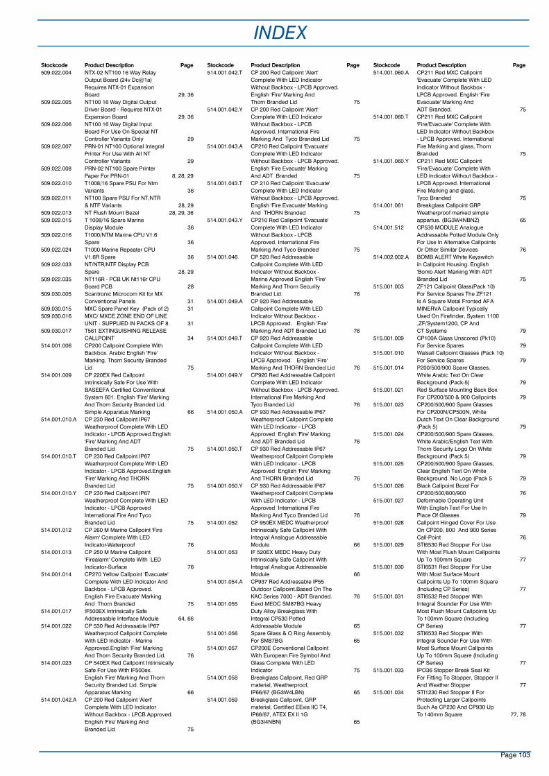
INDEX
Page 103
Stockcode Product Description Page509.022.004 NTX-02 NT100 16 Way Relay
Output Board (24v Dc@1a) Requires NTX-01 Expansion Board 29, 36
509.022.005 NT100 16 Way Digital Output Driver Board - Requires NTX-01 Expansion Board 29, 36
509.022.006 NT100 16 Way Digital Input Board For Use On Special NT Controller Variants Only 29
509.022.007 PRN-01 NT100 Optional Integral Printer For Use With All NT Controller Variants 29
509.022.008 PRN-02 NT100 Spare Printer Paper For PRN-01 8, 28, 29
509.022.010 T1008/16 Spare PSU For Ntm Variants 36
509.022.011 NT100 Spare PSU For NT,NTR & NTF Variants 28, 29
509.022.013 NT Flush Mount Bezel 28, 29, 36509.022.015 T 1008/16 Spare Marine
Display Module 36509.022.016 T1000/NTM Marine CPU V1.6
Spare 36509.022.024 T1000 Marine Repeater CPU
V1.6R Spare 36509.022.033 NT/NTR/NTF Display PCB
Spare 28, 29509.022.035 NT116R - PCB UK Nt116r CPU
Board PCB 28509.030.005 Scantronic Microcom Kit for MX
Conventional Panels 31509.030.015 MXC Spare Panel Key (Pack of 2) 31509.030.016 MXC/ MXCE ZONE END OF LINE
UNIT - SUPPLIED IN PACKS OF 8 31509.030.017 T561 EXTINGUISHING RELEASE
CALLPOINT 34514.001.006 CP200 Callpoint Complete With
Backbox. Arabic English 'Fire' Marking. Thorn Security Branded Lid 75
514.001.009 CP 220EX Red CallpointIntrinsically Safe For Use With BASEEFA Certified Conventional System 601. English 'Fire' Marking And Thorn Security Branded Lid. Simple Apparatus Marking 66
514.001.010.A CP 230 Red Callpoint IP67 Weatherproof Complete With LED Indicator - LPCB Approved.English 'Fire' Marking And ADTBranded Lid 75
514.001.010.T CP 230 Red Callpoint IP67 Weatherproof Complete With LED Indicator - LPCB Approved.English 'Fire' Marking And THORN Branded Lid 75
514.001.010.Y CP 230 Red Callpoint IP67 Weatherproof Complete With LED Indicator - LPCB Approved International Fire And Tyco Branded Lid 75
514.001.012 CP 260 M Marine Callpoint 'Fire Alarm' Complete With LED Indicator-Waterproof 76
514.001.013 CP 250 M Marine Callpoint 'Firealarm' Complete With LED Indicator-Surface 76
514.001.014 CP270 Yellow Callpoint 'Evacuate' Complete With LED Indicator AndBackbox - LPCB Approved. English 'Fire Evacuate' Marking And Thorn Branded 75
514.001.017 IF500EX Intrinsically Safe Addressable Interface Module 64, 66
514.001.022 CP 530 Red Addressable IP67 Weatherproof Callpoint Complete With LED Indicator - Marine Approved.English 'Fire' Marking And Thorn Security Branded Lid. 76
514.001.023 CP 540EX Red Callpoint Intrinsically Safe For Use With IF500ex. English 'Fire' Marking And Thorn Security Branded Lid. Simple Apparatus Marking 66
514.001.042.A CP 200 Red Callpoint 'Alert' Complete With LED Indicator Without Backbox - LPCB Approved. English 'Fire' Marking AndBranded Lid 75
Stockcode Product Description Page514.001.042.T CP 200 Red Callpoint 'Alert'
Complete With LED Indicator Without Backbox - LPCB Approved. English 'Fire' Marking AndThorn Branded Lid 75
514.001.042.Y CP 200 Red Callpoint 'Alert' Complete With LED Indicator Without Backbox - LPCB Approved. International Fire Marking And Tyco Branded Lid 75
514.001.043.A CP210 Red Callpoint 'Evacuate' Complete With LED Indicator Without Backbox - LPCB Approved. English 'Fire Evacuate' Marking And ADT Branded 75
514.001.043.T CP 210 Red Callpoint 'Evacuate' Complete With LED Indicator Without Backbox - LPCB Approved. English 'Fire Evacuate' Marking And THORN Branded 75
514.001.043.Y CP210 Red Callpoint 'Evacuate' Complete With LED Indicator Without Backbox - LPCB Approved. International Fire Marking And Tyco Branded 75
514.001.046 CP 520 Red Addressable Callpoint Complete With LED Indicator Without Backbox - Marine Approved English 'Fire' Marking And Thorn Security Branded Lid. 76
514.001.049.A CP 920 Red Addressable Callpoint Complete With LED Indicator Without Backbox - LPCB Approved. English 'Fire' Marking And ADT Branded Lid 76
514.001.049.T CP 920 Red Addressable Callpoint Complete With LED Indicator Without Backbox - LPCB Approved. English 'Fire' Marking And THORN Branded Lid 76
514.001.049.Y CP920 Red Addressable Callpoint Complete With LED Indicator Without Backbox - LPCB Approved. International Fire Marking And Tyco Branded Lid 76
514.001.050.A CP 930 Red Addressable IP67Weatherproof Callpoint Complete With LED Indicator - LPCB Approved English 'Fire' Marking And ADT Branded Lid 76
514.001.050.T CP 930 Red Addressable IP67Weatherproof Callpoint Complete With LED Indicator - LPCB Approved English 'Fire' Marking And THORN Branded Lid 76
514.001.050.Y CP 930 Red Addressable IP67Weatherproof Callpoint Complete With LED Indicator - LPCB Approved International FireMarking And Tyco Branded Lid 76
514.001.052 CP 950EX MEDC Weatherproof Intrinsically Safe Callpoint With Integral Analogue Addressable Module 66
514.001.053 IF 520EX MEDC Heavy Duty Intrinsically Safe Callpoint With Integral Analogue Addressable Module 66
514.001.054.A CP937 Red Addressable IP55 Outdoor Callpoint.Based On The KAC Series 7000 - ADT Branded. 76
514.001.055 Eexd MEDC SM87BG Heavy Duty Alloy Breakglass With Integral CP530 Potted Addressable Module 65
514.001.056 Spare Glass & O Ring Assembly For SM87BG 65
514.001.057 CP200E Conventional Callpoint With European Fire Symbol And Glass Complete With LED Indicator 75
514.001.058 Breakglass Callpoint, Red GRP material, Weatherproof,IP66/67 (BG3W4LBN) 65
514.001.059 Breakglass Callpoint, GRP material, Certified EExia IIC T4, IP66/67, ATEX EX II 1G (BG3I4NBN) 65
Stockcode Product Description Page514.001.060.A CP211 Red MXC Callpoint
'Evacuate' Complete With LED Indicator Without Backbox - LPCB Approved. English 'Fire Evacuate' Marking AndADT Branded. 75
514.001.060.T CP211 Red MXC Callpoint 'Fire/Evacuate' Complete With LED Indicator Without Backbox - LPCB Approved. International Fire Marking and glass, Thorn Branded 75
514.001.060.Y CP211 Red MXC Callpoint 'Fire/Evacuate' Complete With LED Indicator Without Backbox - LPCB Approved. International Fire Marking and glass, Tyco Branded 75
514.001.061 Breakglass Callpoint GRP Weatherproof marked simple appartus. (BG3W4NBNZ) 65
514.001.512 CP530 MODULE Analogue Addressable Potted Module Only For Use In Alternative Callpoints Or Other Similar Devices 76
514.002.002.A BOMB ALERT White Keyswitch In Callpoint Housing. English 'Bomb Alert' Marking With ADT Branded Lid 75
515.001.003 ZF121 Callpoint Glass(Pack 10) For Service Spares The ZF121 Is A Square Metal Fronted AFAMINERVA Callpoint Typically Used On Firefinder, System 1100 ,ZF/System1200, CP And CT Systems 79
515.001.009 CP100A Glass Unscored (Pk10) For Service Spares 79
515.001.010 Walsall Callpoint Glasses (Pack 10) For Service Spares 79
515.001.014 P200/500/900 Spare Glasses, White Arabic Text On Clear Background (Pack-5) 79
515.001.021 Red Surface Mounting Back Box For CP200/500 & 900 Callpoints 79
515.001.023 CP200/500/900 Spare Glasses For CP200N/CP500N, White Dutch Text On Clear Background (Pack 5) 79
515.001.024 CP200/500/900 Spare Glasses, White Arabic/English Text With Thorn Security Logo On White Background (Pack 5) 79
515.001.025 CP200/500/900 Spare Glasses, Clear English Text On White Background. No Logo (Pack 5 79
515.001.026 Black Callpoint Bezel For CP200/500/800/900 76
515.001.027 Deformable Operating Unit With English Text For Use In Place Of Glasses 79
515.001.028 Callpoint Hinged Cover For Use On CP200, 800 And 900 SeriesCall-Point 76
515.001.029 STI6530 Red Stopper For Use With Most Flush Mount Callpoints Up To 100mm Square 77
515.001.030 STI6531 Red Stopper For Use With Most Surface Mount Callpoints Up To 100mm Square (Including CP Series) 77
515.001.031 STI6532 Red Stopper With Integral Sounder For Use With Most Flush Mount Callpoints Up To 100mm Square (Including CP Series) 77
515.001.032 STI6533 Red Stopper With Integral Sounder For Use With Most Surface Mount Callpoints Up To 100mm Square (Including CP Series) 77
515.001.033 IPO36 Stopper Break Seal Kit For Fitting To Stopper, Stopper II And Weather Stopper 77
515.001.034 STI1230 Red Stopper II For Protecting Larger Callpoints Such As CP230 And CP930 Up To 140mm Square 77, 78

Page 104
INDEXStockcode Product Description Page515.001.035 STI3150 Red Weather Stopper II
For Weather Proofing And Protecting Larger Callpoints Such As CP230 And CP930 Up To140mm Square 77, 78
515.001.036 STI6535 Red Weather Stopper For Weather Proofing And Protecting Callpoints And Other Devices Up To 100mm Square 77, 78
515.001.037 STI6400 Exit Stopper - Red Emergency Exit Alarm - Battery Operated 78
515.001.038 STI6200 Fire Extinguishing Theft Stopper - Red - Battery Operated 78
515.001.039 CO23 Spare key for Exit STOPPER 78, 79
515.001.041 Spare Key For IF520EX Callpoint And Other MEDC SM87PB Based Callpoints 66
515453 612H Conventional 135F Rate Of Rise Heat Detector - UL Listed - Grinnell Branded 45
515455 632H Conventional Heat Detector 200F Degrees Fixed Temperature - UL Listed - Grinnell Brand 45
515456 612I Conventional Ion Chamber Detector - UL Listed - Grinnell Branded 45
515457 612P Conventional Optical Smoke Detector - UL Listed-Grinnell Branded 44
515458 612PH Conventional High Performance Optical Smoke Detector - UL Listed - Grinnell Branded 44
515461 912H Analogue Addressable Fixed/ Rate Of Rise Heat Detector -UL Listed-Grinnell Branded 42
515462 912I Analogue Addressable Ion Chamber Smoke Detector -UL Listed-Grinnell Branded 42
515463 912P Analogue Addressable Optical Smoke Detector - UL Listed - Grinnell Branded 41
515464 912PH Analogue Addressable High Performance Optical SmokeDetector -UL Listed - Grinnell Branded 41
515467 4B UL 4B Lo Pro Detector Base (4")Grinnell Branded 48
515468 6B UL 6B Lo Pro Detector Base (6")-Grinnell Branded 48
515472 M900K 900 Series Smart Card Address Key 53
515474 M900F Smart Card Address Key Programmer Freestanding 53
515475 M900C Smart Card Address Key Programmer For Use With A Laptop Computer Running MINERVA/TFX Configuration Software - CONSYS 53
515484 Spare Fireray 2000 Beam Detector Transmitter 69
515485 Spare Fireray 2000 Beam Detector Receiver 69
515487 Spare Fireray2000 Main PCB 69515590 600RBA UL Approved M600
Series Relay Base Assembly 52515591 900RBA UL Approved M900 Series
Relay Base Assembly 52516.009.006 S111 Infra Red Flame Detector
Solar Blind Plug And Socket Connection 60
516.009.007 S112 Infra Red Flame Detector Non Solar Blind Plug And Socket Connection 60
516.009.008 S121 Infra Red Flame Detector Solar Blind Screw Terminal Connections 60
516.009.014 S121 Infra Red Flame Detector Solar Blind Screw Terminal Connections (Pyrotronics) FM Approved 60
516.009.019 S122 Infra Red Flame Detector Non Solar Blind Screw Terminal Connections (Pyrotronics) 60
516.009.022 S161 Infra Red Flame Detector Solar Blind Complete With Built In Intrinsically Safe Isolation Area 60
Stockcode Product Description Page516.009.023 S131 Infra Red Flame Detector
Solar Blind 60516.009.028 S131 Infra Red Flame Detector
Solar Blind Pyrotronics 60516.014.017 H600 60°C Fixed Temp Heat
Detector 65516.014.018 H900 90°C Fixed Temp Heat
Detector 65516.014.019 H602 60°C Fixed Temp Heat
Detector C/W Local Indicator 65516.014.020 H902 90°C Fixed Temp Heat
Detector C/W Local Indicator 65516.014.021 H601 60°C Fixed Temp Heat
Detector - Remote Indicator 65516.014.025 H904 90°C Fixed Temp Heat
Detector C/W Local Indicator Intrinsically Safe 65
516.014.026 H904 90°C Fixed Temp HeatDetector C/W Local Indicator Intrinsically Safe 65
516.015.006.A FR2000 Optical Beam Smoke Detector - ADT 69
516.015.006.T FR2000 Optical Beam Smoke Detector-Thorn 69
516.015.007 Fireray 2000 Retro-reflector 100x100mm Each. Can be Used Individually or in Banks of 6 for Longer Range 69
516.015.008 Fireray 2000 Alignment Tool 69516.015.009 STI9625 Beam Detector Guard
- For Use With Fireray 2000 Beam Detectors And Other Large Detectors 78
516.015.011 Fireray 50R 5- 50 Metre Reflective Beam Smoke Detector 12V-24Vdc 69
516.015.012 Fireray 100R 50-100 Metre Reflective Beam Smoke Detector 12V- 24Vdc 69
516.016.005 LD40-BLUE High Resistance Sensor Cable Blue-200m Reel 70
516.016.006 LD-40-BLCK High Resistance Sensor Cable Black-200m Reel (Nylon Sheath Suitable For Petrochemical Exposure Etc) 70
516.016.010 LD40 EOL Termination Kit 70516.016.011 LD40 In-Line Jointing Kit 70516.016.012 LD40 ANALYSER MODULE.
ALARMLINE SERIES 4LHD K82012 70
516.016.111 MXF100 CONTROLLER C/W 3 TIER WALL MOUNTED CABINET AND PSU 71
516.016.112 MXF-SL SENSOR LINE THERMOPLASTIC SENSOR CABLE (1KM REEL) 71
516.016.113 MXF-SS SENSOR TUBE STAINLESS STEEL SENSOR CABLE (1KM REEL) 71
516.018.001 VLP-012 LaserPLUS Detector + Programmer + Display 55
516.018.002 VLP-002 LaserPLUS Detector + Display 55
516.018.003 VLP-000 LaserPLUS Detector 55516.018.004 VLS-214 FD7 Scanner +
Programmer + Display 56516.018.005 VLS-204 FD7 Scanner + Display 56516.018.006 VLS-200 FD7 Scanner 56516.018.007 VLS-314 FD12 Scanner +
Programmer + Display 56516.018.008 VLS-304 FD12 Scanner + Display 56516.018.009 VLS-300 FD12 Scanner 56516.018.010 VLC-500-RO VESDA
LaserCOMPACT With Relay Outputs 55
516.018.011 VLC-505-VN VESDALaserCOMPACT with VESDAnet Interface 55
516.018.013 VLP-400 LaserPLUS Detector With Fire/Ok LED 55
516.018.016 VLS-600 FD7 LaserPLUS Scanner With FIRE OK LED 56
516.018.019 VLS-700 FD12 LaserPLUS Scanner With FIRE OK LED 56
516.018.101 VRT-100 Remote Programmer 56516.018.102 VRT-200 Remote Display Including
7 Relays 56516.018.103 VRT-300 Remote VESDAnet
Socket 56516.018.104 VRT-400 Remote Scan
Display Including 7 Relays 56
Stockcode Product Description Page516.018.106 VRT-600 Remote Detector Display
- No Relays 56516.018.107 VRT-700 Remote Scanner Display
- No Relays 56516.018.108 VRT-800 Remote Scanner Display
With 12 Relays 56516.018.119 VRT-J00 LaserCOMPACT Remote
Display Complete With 7 Relays 56516.018.120 VRT-K00 LaserCOMPACT Remote
Display With No Interface Relays 56516.018.201 VSR-2000 19" Subrack With 1
Detector Display + 3 Blanks 57516.018.203 VSR-2210 19" Subrack Two
Detector Displays, Programmer And 1 Blank 57
516.018.204 VSR-2221 19" Subrack With 3Detector Displays And Programmer 57
516.018.206 VSR-2222 19" Sub Rack With Four Detector Displays 57
516.018.210 VSR-CUSTOM Custom Sub-Rack Housing Includes Cost Of Custom Building 4 Vsu Sub Rack Units 57
516.018.214 VSU-E Blank Scanner Sub-UnitWith 7 Interface Relays For
Custom Sub-Racks 57516.018.219 VSU-J LaserCOMPACT Display
Sub-Unit With 7 Relays For Ordering In Custom Sub-Racks 57
516.018.260 VSU-0 Blank Sub Unit 57516.018.261 VSU-1 Programmer Sub Unit 57516.018.262 VSU-2 Detector Display Sub
Unit+7 Relays 57516.018.265 VSU-5 Blank Subunit With 7
Relays 57516.018.268 VSU-8 Scanner Display Subunit
With 12 Relays 57516.018.269 VSU-9 Blank Display Subunit
With 12 Relays 57516.018.270 VESDA Scanner Decal-Swedish 58516.018.301 020-052 19 Inch Rack Enclosure
(2 Rows) 57516.018.302 020-055 19 Inch Rack Enclosure
(5 Rows) 57516.018.303 020-050 IP65 Enclosure 57516.018.401 VHH-1000 Hand Held Programmer
Plus Leads 57516.018.402 VHX-0200 PC Link HLI (High
Level Interface) Plus Leads (Mk2) 57516.018.403 VSW-004 Vconfig Basic
Configuration Software 57516.018.404 VSW-002 Aspire For Windows
Aspirating Design Software 57516.018.407 014.015 VESDA 24v Dc 2a Power
Supply and Charger 57516.018.501 VSP-002 Detector Display (Spare) 58516.018.502 VSP-004 Scanner Display (Spare) 58516.018.503 VSP-001 Programmer (Spare) 58516.018.504 VSP-005 Filter Cartridge (Spare) 58516.018.505 VSP-019 Filter Cover Door (Spare) 58516.018.506 VSP-006 Spare Detector Chassis +
Manifold 58516.018.508 VSP-008 Spare Remote Termination
Card 7 Relays 58516.018.509 VSP-009 Spare Scanner Chassis
+ Manifold 58516.018.514 VSP-014 Spare Header
Termination Card 7 Relays 58516.018.515 VSP-015 Spare Aspirator Fan 58516.022.001 MS302EX Infra Red Flame
Detector 63516.030.002 MF501EX Analogue Addressable
Ion Chamber Smoke Detector 62516.031.002 MR501EX Analogue Addressable
Optical Smoke Detector 63516.031.005 MR501TEX Analogue Addressable
High Performance Optical Smoke Detector 62
516.032.001 MS502EX Addressable Infra Red Flame Detector 63
516.033.002 MD501EX Analogue Addressable Heat Detector 63
516.033.011 T4E60X T54B Point Type Heat Detector - 60°C 64
516.033.012 T4E90X T54B Point Type Heat Detector - 90°C 64
516.033.013 T4E100X T54B Point Type Heat Detector - 100°C 64
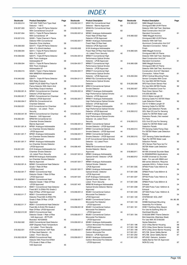
Stockcode Product Description Page516.033.014 T4E145X T54B Point Type Heat
Detector - 145°C 64516.037.003 S231F+ Triple IR Flame Detector
With Conventional Circuit I/F 59516.037.004 S231I+ Triple IR Flame Detector
With Convenitonal I/F 59516.037.015 S232f+ Triple Channel Ir Flame
Detector With Conventional Detection Zone Interface 59
516.038.003 S241F+ Triple IR Flame Detector With 4 To 20mA Interface 59
516.038.004 S241I+ Triple IR Flame Detector With 4 To 20mA I/F 59
516.039.003 S251F+ Triple IR Flame Detector With Thorn Analogue Addressable I/F 59
516.039.004 S251I+ Triple IR Flame Detector With Thorn Analogue Addressable I/F 59
516.039.015 S252f+ Triple Ir Flame Detector With MINERVA Addressable Interface 59
516.040.002 S261F+ Triple IR Flame Detector With Relay Outputs 59
516.040.012 S262F PLUS S262f Plus Triple IR Flame Detector With Alarm And Fault Relay Output Interface 59
516.050.001.A MF601 Conventional Ion Chamber Detector LPCB Approved 45
516.050.001.T MF601 Conventional Ion Chamber Detector LPCB Approved 45
516.050.004.Y MF601Ex Conventional Ion Chamber Detector 62
516.050.031 612I Conventional Ion Chamber Detector - UL Listed - Thorn Security 45
516.050.041.W MF613 Conventional Ion Chamber Detector - VdS Approved 45
516.050.401 MF601M Conventional Ion Chamber Smoke DetectorMarine Approved 45
516.051.001.A MF901 Analogue Addressable Ion Chamber Smoke Detector -LPCB Approved 42
516.051.001.T MF901 Analogue Addressable Ion Chamber Smoke Detector -LPCB Approved 42
516.051.001.Y MF901 Analogue Addressable Ion Chamber Smoke Detector -LPCB Approved 42
516.051.031 912I Analogue Addressable Ion Chamber Smoke Detector -UL Listed-Thorn Security 42
516.051.401 MF901M Analogue Addressable Ion Chamber Smoke DetectorMarine Approved 42
516.052.001.A MD601 Conventional Heat Detector Grade 1 Rate Of Rise -LPCB Approved 45
516.052.001.T MD601 Conventional Heat Detector Grade 1 Rate Of Rise -LPCB Approved 45
516.052.001.Y MD601 Conventional Heat Detector Grade 1 Rate Of Rise -LPCB Approved 45
516.052.011.A MD611 Conventional Heat Detector Fixed 60°C & EN54 Pt5 Grade 2 Rate Of Rise -LPCB Approved 45
516.052.011.T MD611 Conventional Heat Detector Fixed 60C & EN54 Pt5 Grade 2 Rate Of Rise -LPCB Approved 45
516.052.011.Y MD611 Conventional Heat Detector Fixed 60c & En54 Pt5 Grade 2 Rate Of Rise -LPCB Approved 45
516.052.013.W MD613 Conventional Heat Detector Grade 1 Rate of Rise- VdS Approved - ZETTLER Branded K07226455 45
516.052.022 632H Conventional Heat Detector 200F Degrees Fixed Temperature - UL Listed - Thorn Security 45
516.052.031 612H Conventional 135F Rate Of Rise Heat Detector - UL Listed - Thorn Security 45
516.052.033.W MD623 Conventional Heat Detector 60C Fixed And EN54 PT5 Grade 2 Rate of Rise - VdS Approved 45
Stockcode Product Description Page516.052.041.Y MD611Ex Conventional Heat
Detector - Marine Approved 63516.052.051.Y MD601Ex Conventional Heat
Detector 63516.053.001.A MD901 Analogue Addressable
Fixed/ Rate Of Rise Heat Detector LPCB Approved 42
516.053.001.T MD901 Analogue Addressable Fixed/ Rate Of Rise Heat Detector LPCB Approved 42
516.053.002 912H Analogue Addressable Fixed/ Rate Of Rise Heat Detector -UL Listed-Thorn Security 42
516.054.001.A MR601T Conventional High Performance Optical Smoke Detector - LPCB Approved 44
516.054.001.T MR601T Conventional High Performance Optical Smoke Detector - LPCB Approved 44
516.054.001.Y MR601T Conventional High Performance Optical Smoke Detector - LPCB Approved 44
516.054.011.Y MR601TEx Conventional High Performance Optical Smoke Detector 62
516.054.041.W MR613 Conventional Optical Smoke Detector 44
516.055.001.A MR901T Analogue Addressable High Performance Optical SmokeDetector -LPCB Approved 41
516.055.001.T MR901T Analogue Addressable High Performance Optical SmokeDetector -LPCB Approved 41
516.055.001.Y MR901T Analogue Addressable High Performance Optical SmokeDetector -LPCB Approved 41
516.055.031 912HP Analogue Addressable High Performance Optical SmokeDetector -UL Listed-Thorn Security 41
516.056.001.A MR601 Conventional Optical Smoke Detector - LPCB Approved 44
516.056.001.T MR601 Conventional Optical Smoke Detector - LPCB Approved 44
516.056.001.Y MR601 Conventional Optical Smoke Detector - LPCB Approved 44
516.056.031 612P Conventional Optical Smoke Detector - UL Listed-Thorn Security 44
516.056.401 MR601M Conventional Optical Smoke Detector Marine Approved 44
516.057.001.A MR901 Analogue Addressable Optical Smoke Detector -LPCB Approved 41
516.057.001.T MR901 Analogue Addressable Optical Smoke Detector -LPCB Approved 41
516.057.001.Y MR901 Analogue Addressable Optical Smoke Detector -LPCB Approved 41
516.057.031 912P Analogue Addressable Optical Smoke Detector - UL Listed- Thorn Security 41
516.057.401 MR901M Analogue Addressable Optical Smoke Detector Marine Approved 41
516.058.001.A MU601 Conventional Carbon Monoxide Fire Detector - LPCB Approved 44
516.058.001.T MU601 Conventional Carbon Monoxide Fire Detector - LPCB Approved 44
516.058.001.W MU601 Conventional Carbon Monoxide Fire Detector - LPCB Approved 44
516.058.001.Y MU601 Conventional Carbon Monoxide Fire Detector - LPCB Approved 44
516.059.001.A MU901 Analogue Addressable Carbon Monoxide Fire Detector - LPCB Approved 41
516.059.001.T MU901 Analogue Addressable Carbon Monoxide Fire Detector - LPCB Approved 41
516.059.001.Y MU901 Analogue Addressable Carbon Monoxide Fire Detector - LPCB Approved 41
Stockcode Product Description Page516.060.021 S860 Meggitt Avionics
Omniguard 860 UV/IR Flame Detector With Self Test. Stainless Steel Construction And 3/4"Standard Connection 61
516.060.022 "S860 Meggitt Avionics Omniguard 860 UV/IR Flame Detector With Self Test. Aluminium Construction And 3/4"Standard Connection. Yellow
Finish 61516.060.025 S660 Meggitt Avionics
Omniguard 660 UV Flame Detector With Self Test. Stainless Steel Construction And 3/4" Standard Connection 61
516.060.026 S660 Meggitt Avionics Omniguard 660 UV Flame Detector With Self Test. Aluminium Construction And 3/4" Standard Connection. Yellow Finish 61
516.200.004 SPS/V Vertical Mounting Probe Sensor Complete With Cover For Use With DETEK Panels 92
516.200.006 SFD Face Down Sensor Pad For Use With DETEK Panels 92
516.200.007 SFD/C Protective Cover For Face Down Sensor Pad - 516.200.006 Sfd 92
516.200.010 CD/5 5 Metre Length Of Sensing Cable For DETEK Water Leak Detection Panels 92
516.200.011 CD/10 10 Metre Length Of Sensing Cable For DETEK Water Leak Detection Panels 92
516.200.012 SOL Start Of Line For Sensing Cable For DETEK Water Leak Detection Panels ( Not needed For Pads 92
516.200.013 EOL End Of Line For Sensing Cable For DETEK Water Leak Detection Panels 92
516.200.014 FFI Sensing Cable Fixing Clips For DETEK Water Leak Detection Panels 92
516.200.015 CDT Sensing Cable Identification Tags For DETEK Water Leak Detection Panels 92
516.200.016 SFU Sensor Pad Face Up For DETEK Water Leak Detection Panels 92
516.800.911 901SB Universal Sounder Base for BS5839/EN54 Applications 49
516.800.912 912SB Universal UL Sounder base - For use with M900 and 800 series detectors. Requires separate 24Vd.c. Fulleon tones 49
517.001.035 DP450 Probe Tube 450mm & Exhaust 54
517.001.036 DP600 Probe Tube 600mm & Exhaust 54
517.001.037 DP750 Probe Tube 750mm & Exhaust 54
517.001.038 DP900 Probe Tube 900mm & Exhaust 54
517.001.039 DP1200 Probe Tube 1200mm & Exhaust 54
517.001.040 DP1500 Probe Tube 1500mm & Exhaust 54
517.001.120 SYSTEM 601 EOL UNIT (P-10) 64, 66, 68
517.001.130 DHM8 Deckhead Mounting Assembly For H-Series 65
517.001.181 DHM 7 Earthing Strip (Spare) For Use As Earthing Strip On Deckhead Mounts 53
517.001.184 S100/200 BRKT Flame Detector Brkt Assembly (Stainless Steel) For Use With All S100/200 Series Detectors 61
517.001.196 UC2 4,Way Barrier Housing 68517.001.198 MT2 2,Way Zener Barrier Housing 68517.001.199 MT5 5,Way Zener Barrier Housing 68517.001.201 MTL728 Zener Safety Barrier 67517.001.202 MTL788 Zener Safety Barrier 67517.001.203 MTL3021 Galvanic Isolation
Safety Barrier Not CE Approved NON EU only 67
INDEX
Page 105

Page 106
Stockcode Product Description Page517.001.204 MTL3043 Galvanic Isolation
Safety Barrier Not CE Approved Non EU only 67
517.001.205 ERL7 Earth Rail I.S.Systems 68517.001.206 ETM7 Earth Termination
Connection System 68517.001.207 IMB7 Insulating Mounting Block 68517.001.224 SOLO704 Adaptor Tube B -
Adapts SOLO 100 / 101 Pole Sets For TYCO Detector Changers And Testers 59, 72
517.001.226 SOLO101 Extension Tube 1.3m Long For Use With 517-001-230 Telescopic Extension Pole 72
517.001.230 SOLO100 Telescopic Extension Pole 1.26m To 4.5m Long 59, 72
517.001.231 DHM69 MARINE Deckhead Mounting For M600/900 Series 53, 64
517.001.233 Carbon Monoxide Detector Field Test Kit With 24 Brickets For Use With SOLO302/330 72
517.001.234 Carbon Monoxide Fire Detector Field Test Kit Spare Bricks (Pack Of 24) 72
517.001.240 SOLO200 Universal Detector Changer For Use With Various Manufacturers Detectors 72
517.001.242 SOLO720 Spare Battery Baton For Use With SOLO450/460 Tester 72
517.001.243 SOLO724 Spare Mains/Car Battery Charger For SOLO720 Battery Baton 72
517.001.244 MTL5061 2 Channel Galvanic Isolator For Conventional Detector Zone - Used On BASEEFAApproved System 601 67
517.001.245 MTL5021 I.S. Sounder Driver 67517.001.246 MTL7128+ Zener Safety Barrier
For Conventional Detection Circuits Designed In Accordance With System 601 67
517.001.247 DX170 Enclosure For MTL5000 Or 7000 Series Barriers 68
517.001.248 DX070 Enclsoure MTL5000 Or 7000 Series Barriers 68
517.001.254 Cordless Heat Detector Tester Kit 72517.001.255 Aerosol Smoke Dispenser
Solo 330-006 72517.001.256 Aerosol Smoke Canisters
Solo A3-006 72517.001.264 SOLO610 Protective Carry /
Storage Bags - For SOLO Detector Test Kit Items and Others 72
517.017.005 VESDA LBL Sampling Point Label 57517.017.006 VESDA LBL Aspirating Pipe Label 57517.025.002 M300EX Mounting Base 64517.025.010 M300/M500 Base Lock Kit 64517.025.021 MP35 Duct Probe Unit For
M300/500 Series 54517.025.022 MB35 Flush Mounting Kit For
M300/400/500 Series 64517.025.026 T35 Skirt Changer Tool For Use
With M300/400/500 Series 72517.025.027 SMP35 Duct Probe Unit Stainless
Steel For M300/500 Series 54517.025.028 DPS450 Probe Tube Stainless
Steel 450mm & Exhaust 54517.025.029 DPS600 Probe Tube Stainless
Steel 600mm & Exhaust 54517.025.030 DPS750 Probe Tube Stainless
Steel 750mm & Exhaust 54517.025.031 DPS900 Probe Tube Stainless
Steel 900mm & Exhaust 54517.025.033 DPS1500 Probe Tube Stainless
Steel 1500mm & Exhaust 54517.025.035 SMP69 Stainless Steel Duct Probe
Unit And Universal Detector Base For M600/900 Series (EN54) 54
517.025.036 MP69 Duct Probe Unit And Base For M600/900 Series (EN54) 54
517.035.002 M500EX Mounting Base 64517.035.006 M500 Protective Cover. 64517.035.007 M520 Anciliary Cover For Use
With M520 Modules and M800 Series Ancilliaries 14
517.035.012 DM520 MINERVA ConventionalDetector Module - Allows One Conventional Detection Zone ToBe Interfaced To The Loop 12
Stockcode Product Description Page517.035.017 MDM521 MINERVA Multi Circuit
Conventional Detector Module - For Up To 8 Conventional Zones 12
517.035.018 DM520/M520 Detector Module And Cover AssembLED 12
517.050.001 M600/800/900 4" Universal Mounting Base for LPCB, VdS Approved Detectors 48
517.050.002.A SA600/900 Low Profile Line Shorting Adaptor Commissioning Tool - ADT Branded 53
517.050.003.A CA600 Low Profile Line Continuity Adaptor Commissioning Tool - ADT Branded 53
517.050.003.T CA600 Low Profile Line Continuity Adaptor Commissioning Tool 53
517.050.004 M69 Detector Changer For Use With M600/900 Series 72
517.050.005 Pack Of 100 Detector Locking Pins For M600/900 Series 52
517.050.007 M600 Diode Continuity Mounting Base For Conventional Detection Zones Including Callpoints - BS5839 Applications Only 48
517.050.011 W500 White Plastic Coated Steel Protective Cage For M6/900 Series Detectors 53
517.050.015 Volume Adjustment Tool for MKII Sounder Base Range 49
517.050.016 Tyco MK2 Sounder Base Range Colour Code Identification Card (Must Order in Multiples of 100) 50
517.050.601 4B Lo Pro Detector Base (4") Thorn Security Branded 48
517.050.606 6B Lo Pro Detector Base (6")- Thorn Security Branded 48
517.051.002 M900K M900 Smart Card Address Key 53
517.051.007 M900F Smart Card Address Key Programmer Freestanding 53
517.051.008 M900C Smart Card Address Key Programmer For Use With A Laptop Computer Running MINERVA/TFX Configuration Software - CONSYS 53
517.051.402 M900km Smart Card Address Key Marine Approved 53
517.060.001 4651045 Meggitt Avionics Swivel Bracket In Black 61
517.060.002 70991 Meggitt Avionics Swivel Bracket In Stainless Steel 61
517.060.003 MODEL 540 HAND HELD UV/IR TEST GUN FOR USE WITH 860 SERIES DETECTORS 61
517.060.005 Airshield For Omniguard S660 And S860 Flame Detectors 61
517.131.001 24 zone analogue addressable controller, VHF receiver, UHF transmitter, 252 device capacity c/w keypad and VDF display. 2 hardwire sounder circuits. RS232 and RS485 ports. BS5839 and EN 54 Standard. Supplied c/w 2 helical antennas (Not inc Batteries) 93
517.131.002 12 zone analogue addressable controller Panel, VHF receiver,UHF transmitter, 252 device capacity c/w keypad and VFD display. 2 hardwire sounder circuits. RS232 and RS485 ports. BS5839 and EN 54 Standard. Supplied c/w 2 helical antennas (Not inc Batts) 93
517.131.003 VHF aerial c/w 20m RG213 coax. 97517.131.004 Radio manual call point c/w
transmitter, processor, radio address module, battery board (supplied with glass substitute card)-Red 95
517.131.005 Addressable Optical Smoke Detector with 4 sensitivity settings c/w transmitter, processor, radio address module battery board, ceiling mount 94
517.131.006 Addressable Heat Detector with 4 sensitivity settings c/w transmitter, processor, radio address module, battery board, ceiling mount 94
Stockcode Product Description Page517.131.007 Electronic radio sounder c/w
VHF transmitter, UHF receiver,processor, radio address module, battery board 96
517.131.008 Interface input/output unit (used for output signals to activate other equipment) c/w transmitter,processor, radio address module, battery board 97
517.131.009 Analogue addressable optical smoke detector with 4 sensitivity settings c/w transmitter, processor,radio address module battery board, ceiling mount 94
517.131.011 96 zone analogue addressable radio LAN controller, VHF receiver,UHF transmitter, 252 device capacity c/w keypad and VFD display. 2 hardwire sounder circuits RS232 and RS485 ports. BS5839 and EN54 Standard. C/W 2 Helical Antennas and Thermal Printer 93
517.131.012 24 zone analogue addressable radio LAN controller with printer option, VHF receiver, UHF transmitter, 252 device capacity c/w keypad and LCD display with option for VFD display. 2 hardwire sounder circuits RS232 and RS485 ports.c/w 2 helical antennas 93
517.131.013 24 zone analogue addressable radio LAN controller, VHF receiver,UHF transmitter, 252 device capacity c/w keypad and LCD display with option for VFD display.2 hardwire sounder circuits RS232 and RS485 ports. Inc c/w 2 helical antennas & thermal printer 93
517.131.014 12 zone LAN analogue addressable controller Panel with printer option, VHF receiver,UHF transmitter, 252 device capacity c/w keypad and LCD display. 2 hardwire sounder circuits. RS232 and RS485 ports. c/w 2 helical antennas 93
517.131.015 12 zone radio LAN analogue addressable controller with panel mounted event printer,VHF receiver, UHF transmitter,252 device capacity c/w keypad and LCD display. 2 hardwire sounder circuits. RS232 and RS485 ports. c/w 2 helical antennas & thermal printer 93
517.131.016 4 zone radio LAN addressable controller Panel, VHF receiver,UHF transmitter, 252 device capacity c/w keypad and LCD display. 2 hardwire sounder circuits. RS232 and RS485 ports.Supplied c/w 2 helical antennas 93
517.131.017 96 zone analogue addressable controller Panel with panel mounted printer, VHF receiver, UHF transmitter, 252 device capacity c/w keypad and VFD display. 2 hardwire sounder circuits. RS232 and RS485 ports. c/w 2 helical antennas 93
517.131.018 24 zone analogue addressable controller Panel with panel mounted printer, VHF receiver,UHF transmitter, 252 device capacity c/w keypad and LCD display with option for VFD display. 2 hardwire sounder circuits. RS232 and RS485 ports c/w 2 helical antennas 93
517.131.019 4-Zone Addressable Control Panel VHF receiver, UHF transmitter, 252 device capacity c/w keypad and LCD display. 2 hardwire sounder circuits. RS232 and RS485 ports. BS5839 and EN 54 Standard. Supplied c/w 2 helical antennas (batteries are not supplied) 93
INDEX

Page 107
Stockcode Product Description Page517.131.020 VHF dipole half wave antenna
c/w 10m RG58 cable and bracket 97517.131.021 VHF helical aerial c/w BNC
connector 97517.131.022 UHF high gain aerial 97517.131.023 UHF helical antenna c/w BNC
connector 97517.131.024 UHF high gain directional aerial
c/w wall mounding bracket, extension pole and 10m low loss RG213 cable. 97
517.131.025 Transponder signal processor,receiver VHF signals from local devices and transmits on UHF to receiver installed adjacent to main controller. The transponder requires 230v supply and is complete with integral PSU. Unit is fitted with 2 helical aerials 95
517.131.026 Transponder for 4-zone addressable system, receiver VHF signals from local devices and transmits on UHF to receiver installed adjacent to main controller.Requires 230V and is complete with an integral PSU Unit is fitted with 2 helical aerials 95
517.131.027 VHF remote radio receiver c/w integral PSU. Receives signal from VHF transmitters 95
517.131.028 UHF remote radio receiver.Receives UHF signal from transponder / processor 95
517.131.029 Heat detector with 4 sensitivity settings c/w transmitter, processor,radio address module, battery board, ceiling mount (complete) 94
517.131.030 Combined Multi-Sensor (Analogue addressable optical smoke & Heat) 95
517.131.031 Combined sounder/analogue optical smoke detector c/w VHF transmitter, UHF receiver, analogue addressable optical smoke detector with 4 sensitivity settings and 90 dbA electronic sounder including 3 x “C” alkaline batteries and 3 x “AA” alkaline batteries. 95
517.131.032 Combined sounder/heat detector c/w VHF transmitter, UHF receiver,analogue addressable heat detector with 4 sensitivity settings and 90 dbA electronic sounder including 3 x “C” alkaline batteries and 3 x “AA” alkaline batteries. 95
517.131.033 Analogue addressable optical smoke detector sensor (Replacement only) 97
517.131.034 Heat detector sensor (Replacement only) 97
517.131.035 Addressable transmitter / processor / battery 97
517.131.036 Addressable optical smoke detector sensor (Replacement only) 97
517.131.037 Addressable Heat detector sensor (Replacement only) 97
517.131.038 Addressable transmitter / processor / battery 97
517.131.039 Radio manual call point c/w transmitter, processor, radio address module, battery board (supplied with glass substitute card) - Yellow 95
517.131.040 Weather proof red call point c/w transmitter, processor, battery board and glass substitute card 95
517.131.041 Hard-wired call point (For use with Sounder 5320/R) 95
517.131.042 Hard-wired call point (For use with all versions of controller) 95
517.131.043 Electronic radio sounder c/w VHF transmitter, UHF receiver,processor, radio address module, battery board Red 96
517.131.044 Electronic radio sounder c/w VHF transmitter, UHF receiver,processor, radio address module, battery board - white case 96
Stockcode Product Description Page517.131.045 Radio sounder and red strobe
unit 96517.131.046 White radio sounder and red
strobe unit 96517.131.047 Red radio strobe unit 96517.131.048 White boxed radio red strobe unit 96517.131.049 Red radio sounder with auxiliary
contact input 96517.131.050 Red Master radio sounder c/w
connections for up to 1 monitored slave voice sounder units, VHF transmitter, UHF receiver,processor, radio address module 96
517.131.051 Red slave radio sounder - For connection to 5-5350 96
517.131.052 Red voice sounder c/w VHF transmitter, UHF receiver,processor, radio address module, battery board, 4 on-board messages activated from any EMS controller 96
517.131.053 Voice sounder/strobe c/w VHF transmitter, UHF receiver,processor, radio address module, battery board, 4 on-board messages activated from any EMS controller 97
517.131.054 White voice sounder c/w VHF transmitter, UHF receiver,processor, radio address module, battery board, 4 on-board messages activated from any EMS controller 96
517.131.055 Voice sounder/strobe c/w VHF transmitter, UHF receiver,processor, radio address module, battery board, 4 on-board messages activated from any EMS controller 97
517.131.056 Weatherproof voice sounder c/w VHF transmitter, UHF receiver,processor, radio address module, battery board, 4 on-board messages activated from any EMS controller 97
517.131.057 Master Voice Unit c/w connections for up to 1 monitored slave voice sounder units, VHF transmitter, UHF receiver, processor,radio address module, battery board, 4 on-board messages activated from any EMS controller 97
517.131.058 Slave Voice Unit For connection to 5-5381 with it’s own monitored battery supply 97
517.131.059 Addressable Interface input/output unit (used for output signals to activate other equipment) c/w transmitter, processor, radio address module, battery board 97
517.131.060 Interface input/output unit (used for output signals to activate other equipment) c/w transmitter,processor, radio address module, battery board, external antenna and housed in metal case 97
517.131.061 Plant I/O shunt unit – for plant isolation during test mode (4 zone) 97
518.003.003 77CR19 Emergency Cable Release 24v D.C. 39
518.003.004 77CR19 Emergency Cable Release 240v A.C. 39
518.004.004 DRU/240 High Quality TEPG Door Release Magnet Set 240v Ac Complete With Keeper Plate 39
518.004.005 DRU/24 High Quality TEPG Door Release Magnet Set 24v.Dc Complete With Keeper Plate 39
519.001.007 Door Release Button UK Single Gang Mounting - With Danger Mains Text 39
525.001.005 Fire Notice Frame 212mm X 297mm 90
525.001.006 Fire Notice Frame 280mm X 356mm 90
525.001.007 Fire Notice Frame 483mm X 737mm 90
525.001.008 Fire Notice Frame 483mm X 367mm 90
Stockcode Product Description Page526.001.016.T T510 Extinguishing - Main To
Reserve Change Over Keyswitch Unit With Two Keys - Thorn Branded 33
526.001.018.A Manual Extinguishing Release Unit (Pull Handle Linked To Gas Container Via Steel Cable) 34
526.001.019.A Extinguishing Release Hold Button Unit (To Suit Single Gang UK Style Back Box) 34
526.001.020.A Extinguishing Abort Button Unit(To Suit Single Gang UK Style Back Box) 34
527.001.003 T5XX Top Hat Frangible Insert(Spare) 35
527.001.013 T5XX Frangible Washers (Spare) (pack of 25) 34, 35
527.001.028 Microswitch Lock Keep & Backplate For Deadlock 35
540.001.012 MK2 LMP/F Lamp (Red) / Buzzer Unit Flush Mounting Mk2 Including Single Gang Backbox. LabelLED 'Fire'. 88
540.001.013 MK2 LMP/S Lamp (Red) /BuzzerUnit Surface Mounting Mk2. LabelLED 'Fire'. 88
540.001.030 1W Xenon Beacon Low Profile Clear 24vdc 1watt 88
540.001.031 1W Xenon Beacon Low Profile Blue 24v Dc 1watt 88
540.001.032 1W Xenon Beacon Low Profile Amber 24vdc 1watt 88
540.001.033 1W Xenon Beacon Low Profile Red 24v Dc 1watt 88
540.001.038 Xenon Beacon (0.5 Joule),GRP Material, IP66, Clear Lens (XB8BB024CNR) 89
540.001.039 Xenon Beacon (5 Joule), EExd IIB T5, IP66/67 GRP Material, Red Lens, ATEX EX II 2G (XB11B02406RNBNNNR) 88
540.003.006.T RIL M600/900 Series Remote Indicator LED Square UK Single Gang Mounting - Thorn Branded 53
540.007.001 Heavy Duty IP67 Cast Aluminium Surface Mount Red Lamp Unit 24 Dc. With Indicator Plate LabelLED 'Extinguishing System Operated' 35
540.007.002 Heavy Duty IP67 Cast Alauminium Surface Mount Red/Amber/Green Lamp Unit 24 Dc. With Indicator Plates LabelLED 'Extinguishing System- Operated / Automatic / Manual' (E3 ) 35
540.007.006 I3 IP67 Surface Mount Red/Amber/Green Lamp Unit 24 Dc. LabelLED 'Gas Release', 'Auto', 'Manual' 35
540.007.007 I4 IP67 Surface Mount Red/Amber/Green Lamp Unit 24 Dc With Auto/Manual Keyswitch LabelLED 'Gas Release', 'Auto', 'Manual' 35
541.001.018 1500 5 Way Zone Monitor PCB Can Be Used On Any Monitored Sounder Circuit To Take Up To 5 Spurs Into A Sounder Output. Suitable For Mounting In Control Equipment 90
545.001.007 LI520 MK2 MINERVA Line Isolator Module 11
545.001.008 MI900 Line Isolator Base For Use With M900 Detectors On MINERVA Systems (Also Compatible With TFX Systems But Not UL Approved) 52
545.001.009 LI520ASSY LI520/M520 Line Isolator And Cover AssembLED 11
546.004.006 PI521 MINERVA Plant Interface 13546.004.007 AM921 MINERVA Aspirator
Detector Interface Module For Vision Systems LaserPLUS Aspirating Systems Fits In Detectors, 7 Relay Scanners And 7 Remote Relay Termination Cards (Not Suitable For VRT-200 And VRT-400) 13
INDEX

Page 108
Stockcode Product Description Page547.004.001 PI/SU Din Rail Mounting Kit For
Use With PI521 Or SU521 13, 14555.180.002 MINERVA 16E Front Cover
Assy (Spare) 10555.180.003 MINERVA 80 Front Cover
Assy(Spare) 10555.180.021 CM520 MINERVA Contact
Monitor Module (1 Input) 11555.180.026 CM520/M520 Contact Module
And Cover AssembLED 11557.001.040.A MK2 Sounder Cap Can be used
with SB601 & SB602 sounders ADT Branded (Pk of 5) 49
557.001.040.T MK2 Sounder Cap Can be used with SB601 & SB602 sounders Thorn Branded (Pk of 5) 49
557.001.040.Y MK2 Sounder Cap Can be used with SB601 & SB602 sounders Tyco Branded (Pk of 5) 49
557.180.001 ACPM MINERVA Power Module 2.7amps Non Addressable 8
557.180.002 MINERVA Power Module 2.7amps Addressable 8
557.180.005 MINERVA 80 Way Mimic Driver Module for use with MINERVAand MX panels 7
557.180.010 MINERVA 80 Motherboard PCB (Spare) 10
557.180.012 MINERVA Multi Purpose Interface Module. Available As A Spare For MINERVA Panels And Repeaters Or For Providing Expansion Using XIOM Modules 7
557.180.014 ALXM MINERVA Addressable Loop Expansion Module (2 Loops) For Use With MINERVA 80 5
557.180.016 XIOM MINERVA Input/Output Expansion Module 16 Way for use with MINERVA or MX panels 7
557.180.021 MINERVA Plain Cover Assembly For Use With General Purpose Housings 10
557.180.022 MINERVA Terminal Chamber PCB Assembly 10
557.180.032 MINERVA General Purpose Housing Surface 10
557.180.033 MINERVA General Purpose Housing Flush 10
557.180.034 MINERVA General Purpose Expansion Housing Surface 10
557.180.035.A MINERVA LCD Repeater For Use With MINERVA Analogue Addressable Fire Controller Systems 8
557.180.035.T MINERVA LCD Repeater For Use With MINERVA Analogue Addressable Fire Controller Systems 8
557.180.051 Dc/Dc Convertor Module 7557.180.052 Serial Printer Driver Kit 7, 8557.180.054 MINERVA 16 Mounting Plate
Kit (Spare) 10557.180.055 MINERVA 8/16E Battery Fitting Kit 5557.180.062 LEAD MINERVA Serial Printer
Lead Assembly 8, 9557.180.063 MINERVA MPIM To PC (D25)
Serial Lead Assembly (As Grinnell 940558) 9
557.180.065 MINERVA 80 Battery Fitting Kit 5557.180.076.A MINERVA Wall Mounted Printer
May Be Mounted Adjacent ToSurface Mounting Controllers - ADT Branded 8
557.180.076.T MINERVA Wall Mounted Printer May Be Mounted Adjacent ToSurface Mounting Controllers - Thorn Branded 8
557.180.079 Bezel - Flush Mounting For Wall Mounting Printer 557-180-076 8
557.180.092 MINERVA Loop Power Insertion Module. Converts MINERVA 8 And 16E To Loop Powered Controllers 5
557.180.095 MINERVA Ancillary Stacking Kit For Use With Ancillary Housing 8 557-180-096 14
557.180.096.A MINERVA Ancillary Hsg - 8 For Use With M5xx Ancillary Modules (Can Accommodate Up To 16 M520 Modules With Stacking Kit) 14
Stockcode Product Description Page557.180.096.T ANC8 MINERVA Ancillary Hsg
- 8 For Use With M5xx Ancillary Modules (Can Accommodate Up To 16 M520 Modules With Stacking Kit) 14
557.180.097.A ANC3 MINERVA Ancillary Hsg - 3 For Use With M5xx Ancillary Modules (Can Accommodate Up To3 M520 Modules) 14
557.180.097.T ANC3 MINERVA Ancillary Hsg - 3 For Use With M5xx Ancillary Modules (Can Accommodate Up To 3 M520 Modules) 14
557.180.105 Full CONSYS Software Key (Dongle) 9
557.180.106 Customer/Distributor Software Key (Dongle) 9
557.180.147 TLK V2.36 TLK Firmware Version 2.36 - Spare 4
557.180.148.A Housing For a Combination of 2 X TLO530 OR TLD530 Communication Interfaces (Available Thorn and ADT Branded) 4
557.180.151 RS232/422 Convertor For Use With MLCD Repeater 8
557.180.152 DB9 Male To Male Gender Changer For Use With 557.180.151 8
557.180.155 MINERVA16E Version 12.1 Spare EPROM 9
557.180.156 MINERVA 80 Version 12.1 Spare EPROM 9
557.180.157 MINERVA ALXM Version 12.1 Spare EPROM 9
557.180.159 MINERVA16E Firmware Version 12.2 (With Mos Event Reporting Fix) 9
557.180.160 MINERVA 80 Firmware Version 12.2 (With Mos Event Reporting Fix) 9
557.180.161 MINERVA ALXM Firmware Version 12.2 9
557.180.163 MINERVA 16 PEPROM VERS 12.3 9557.180.164 MINERVA 80 PEPROM VERS 12.3 9557.180.165 MINERVA ALXM PEPROM VERS
12.3 9557.180.167 MINERVA 16 PEPROM KIT V12.4 9557.180.168 MINERVA 80 PEPROM KIT V12.4 9557.180.169 MINERVA ALXM PEPROM KIT
V12.4 9557.180.200 MP MINERVA Main Processor
PCB No Software Fitted 10557.180.202 LEAD Printer Lead Assembly
D Type AngLED For Use With Wall Printer 8
557.180.203 ALXM-LP Addressable Loop Expansion Module Loop Powered(2 Loops) For Use With MINERVA 80 LP 5
557.180.204 M80SPARE Motherboard Loop Powered For Use With MINERVA80 (Spare) 10
557.180.205 LPDCM MINERVA Dc/Dc Convertor Loop Powered 7
557.180.208 Spare Keys (Used On MINERVAControllers 10
557.180.209 Keyswitch Assembly For Use With MINERVA Controllers (Spare) 10
557.180.214 LQ 300 Epson dot matrix alarm printer - 24 pin 80 character 9
557.180.215 TLK530 Thorn Net Network Node Interface Module 4
557.180.217 LPBD521 MINERVA Loop Powered Beam Detector Interface Module For Use With Fireray 2000 13, 70
557.180.218 TLK530G Thorn Net Interface For Thorngraph PC C/W PSU And Housings 4
557.180.219 LEAD Thorn Graph To TLK-530 Connection Cable Between PC And TLK 530G 4
557.180.220 LQ80 Ribbon Black (Spare) for use with LQ 300 plus printer 9
557.180.223 MINERVA Wall Mounting Printing Ribbon (Spare) 8
557.180.234 MINERVA Customer CONSYS V12.1 9
Stockcode Product Description Page557.180.401 T890M MINERVA Marine Analogue
Addressable Controller Supplied with 1 ALXM (2 loops) but can expand to 10 Loops 5
557.180.402 T891 M MINERVA Marine Analogue Addressable Controller 2 Loops 5
557.180.403 T290 M MINERVA Marine Repeater Unit For Use With T890m 5
557.180.404 T291 M MINERVA Marine Repeater Unit For Use With T891m 5
557.180.405 T680 M MINERVA Marine Power Unit 5
557.180.406 TXX M MINERVA Marine Terminal Chamber 10
557.180.407 T891 Front Cover Assembly 10557.180.408 T890 Front Cover Assembly 10557.180.410 TXX M MINERVA Marine Battery
Fitting Kit 5, 10557.180.423 TM520 Timer Module - Non
Addressable 11557.180.424 TXX M MINERVA Marine ALXM 5557.180.452 MINERVA 19" Rack Mounting
Kit For Use With Surface Mounting Housings 10
557.180.454 TXX M MINERVA Marine Bulkhead Mounting Kit 5, 10
557.180.550 MINERVA16E Controller Surface Mounting Complete With P.S.U 5
557.180.553 MINERVA16E Controller Flush Mounting Complete With P.S.U 5
557.180.554 MINERVA16E Repeater Surface Mounting 5
557.180.555 MINERVA16E Repeater Flush Mounting 5
557.180.556 MINERVA 80 Controller Surface Mounting C/W One ALXM Requires P.S.U. 5
557.180.557 MINERVA 80 Controller Flush Mounting C/W One ALXM Requires P.S.U 5
557.180.558 MINERVA 80 Repeater Surface Mounting 5
557.180.559 MINERVA 80 Repeater Flush Mounting 5
557.180.560 MINERVA Power Box (Addressable) Surface Mounting Complete With 2.7 Ahr P.S.U. 8
557.180.561 MINERVA Power Box (Non-Addressable) Surface Mounting Complete With 2.7 Ahr P.S.U 8
557.180.564 MINERVA 8 Controller Surface Mounting Complete With P.S.U. 5
557.180.565 MINERVA 8 Controller Flush Mounting Complete With P.S.U. 5
557.180.566 MINERVA 8 Repeater Surface Mounting Complete With P.S.U. 5
557.180.567 MINERVA 80 Controller Arabic 5557.180.568 MINERVA16E Controller Arabic 5557.180.569 MINERVA 80 Controller Surface
Mounting Loop Powered C/W One ALXM Requires P.S.U. 5
557.180.570 M80LP MINERVA 80 Controller Flush Mounting Loop Powered C/W One ALXM Requires P.S.U. 5
557.180.575 MINERVA16E Mandarin Version 5557.180.576 MINERVA 80 Mandarin Version 5557.180.623 TFX-500M 2 Loop Fire Control
Panel With Red Architectural Door Grinnell Branded In 3 Tier Housing With Fcm/Ocm And 16 LED Indicator 15
557.180.624 TFX-800M Fire Detection Panel With Red Architectural Door And Grinnell Branding In 7 Tier Housing With Fcm/Odm And 80 LED Indicator 15
557.180.625 TFX400 Two Loop Ul/FM Approved Fire Control Panel. Supplied In Grey With Thorn Security Branding. 15
557.180.667 940577 MINERVA MPIM ToPC (D9) Serial Lead 8, 9
557.180.699 TLD530 Thorn Net Direct Line Driver PCB 4
557.180.701 MINERVA 8 Controller Dutch 5557.180.702 MINERVA 80 Controller Dutch 5557.180.703 MINERVA16E Controller Dutch 5
INDEX

Page 109
Stockcode Product Description Page557.180.722 M80 SPARE MINERVA 80 Cover
Assembly Dutch (Spare) 10557.180.831 MINERVA16E Main Processor
PEPROM Vers 12 9557.180.832 MINERVA 80 Main Processor
PEPROM Vers 12 9557.180.833 MINERVA 80 ALXM PEPROM
Vers 12 9558.004.006 C2440 C Range Charger 24v
4 Amp 40558.004.007 TRR-243 24v Dc 3a Transformer /
Rectifier Unit For Door Release Units. Includes 24v Volt Free Relay Interface. 40
558.004.013 C RANGE Housing Type D Complete With Metres 40
558.004.014 C RANGE Housing Type D 40558.004.015 C RANGE Housing Type C
Complete With Metres 40558.004.016 C RANGE Housing Type C 40560.001.012 12v 38Ah Battery 39560.001.013 6v 10Ah Battery 36, 39560.001.015 12v 17Ah Battery 39560.001.016 12V 17AH BATTERY - INVERTED
TERMINALS 39567.001.004 RELAY 5000 Relay 5000 (2 Way
Relay Unit) 90567.005.004 RELAY 5010 Relay 5010 (5 Way
Relay Unit) 90567.005.005 RELAY 5016 Relay 5016 (8 Way
Rly Unit) 90567.007.008 240V MK4 Alarm Relay 240v Ac
Mk4 90567.007.009 24V MK4 Alarm Relay 24v Dc
Mk4 90568.001.006 5016PCB Relay 5016 PCB For 8
Relays 90568.001.007 Relay 5000 Housing Auxiliary
Relay (Small) 90568.001.008 Relay 5010 Housing Auxiliary
Relay (Large) 90568.001.011 MINERVA Relay Module (1 X
24V DC Rated Relay) 11568.001.013 SU521 MINERVA Shop Unit
Interface 14568.001.014 SD520 MINERVA Smoke Damper
Interface Module ( 2 Inputs And 1 Output) 13
568.001.016 MC900 Low Power Relay For Use With Any M900 Low Profile Detector 52
568.001.017 RM520/M520 Relay Module And Cover Assemby LED 11
568.001.018 MC600 Low Power Relay For Use With Any M600 Low Profile Detector - Not Compatible With System 1600 And T880 Series Detection Panels 52
569.001.007 26V RLY Cradle Relay And Retaining Clip 2 C/O 26v Nominal 700 Ohm Coil 5 Amp Used With Relay 5000 And 5010 90
571.07 Universal Mounting Base K07226456 48
571.071 M69 Detector Locking Pin Kit (Pack Of 100) K07226458 52
576.500.004.A Red Bell 6" 240v Ac Solenoid Operated. 'Fire' Text With ADT Branding 84
576.500.004.T Red Bell 6" 240v Ac Solenoid Operated. 'Fire' Text With Thorn Branding 84
576.500.009.A Bell 6" 24v.D.C.Solenoid Operated.'Fire' Text With ADT Branding 84
576.500.009.T Bell 6" 24v.D.C.Solenoid Operated.'Fire' Text With Thorn Branding 84
576.501.001 Yodalarm 3" 24v Dc IP54 96db@1m Frequency 800-1000Hz 30mA 86
576.501.003 Yodalarm 8" 24v.D.C. IP54 rating 112db@1m Frequency 800-1000Hz 330mA YO8 86
576.501.004.A Banshee 24V.DC BS5839 Low Frequency Low Profile Red - 107dba Effective - 15mA (ADT Branded) 85
576.501.004.T Banshee 24V.DC BS5839 Low Frequency Low Profile Red - 107dba Effective - 15mA (Thorn Branded) 85
Stockcode Product Description Page576.501.008.A Banshee 24V DC High Frequency
Low Profile Red - 105dba Effective - 25mA (ADT Branded) 85
576.501.008.T Banshee 24V DC High Frequency Low Profile Red - 105dba Effective - 25mA (Thorn Branded) 85
576.501.011 Banshee/Bedlam Weatherproof Mains Adaptor Pack 240v A.C. To 24v D.C. Use On Any 24v D.C. Banshee Or Bedlam 85
576.501.013 IS28VCL Banshee IS28 BS5839 Low Frequency BASEEFA Certified Intrinsically Safe - Red Sounder - 98dba - 10mA Certificate NO.Ex87B2027 EE xia IIC T5 Suitable to Relplace Banshee IS22B 86
576.501.015.A Bedlam 24V D.C. Low Profile Weatherproof - Red 117dba Effective - 30mA (ADT Branded) 85
576.501.015.T Bedlam 24V D.C. Low Profile Weatherproof - Red 117dba Effective - 30mA (Thorn Branded) 85
576.501.019 Banshee 24v D.C. Slow Whoop Low Profile Red Dutch 86
576.501.022.A Bell 6" 24v D.C. Motorised.'Fire' Text With ADT Branding 81
576.501.022.T Bell 6" 24v D.C. Motorised.'Fire' Text With Thorn Branding 81
576.501.023.A Bell 8" 24v D.C. Motorised. 'Fire' Text With ADT Branding 81
576.501.023.T Bell 8" 24v D.C. Motorised. 'Fire' Text With Thorn Branding 81
576.501.024.A IP66 Banshee Weatherproof24V D.C. BS5839 Low Frequency Low Profile - Red 107dba Effective - 15mA (ADT Branded) 85
576.501.024.T IP66 Banshee Weatherproof 24V D.C. BS5839 Low Frequency Low Profile - Red - 107dba Effective - 15mA (Thorn Branded) 85
576.501.030 Squashni White 24V DC 81576.501.031 Blank Cover Plate White For
Squashni 81576.501.032.A Flush Mounting Square (86 X 86)
Bedroom Sounder 24V D.C.-White - 90dba @ 1M Typical - 7mA (ADT Branded) 85
576.501.032.T Flush Mounting Square (86 X 86) Bedroom Sounder - 24V D.C.-White - 90dba @ 1M Typical - 7ma (Thorn Branded) 85
576.501.033.A Banshee 24V D.C. BS5839 Low Frequency, Low Profile - White- 107dba Effective - 15ma (ADT Branded) 85
576.501.033.T Banshee 24V D.C. BS5839 Low Frequency, Low Profile - White - 107dba Effective - 15mA (Thorn Branded) 85
576.501.034.A MFC1SEA Red ADT UK Firecryer - Single English Message Synchronised Voice Enhanced Sounder. Message Ref. Ak 87
576.501.035.A MFC4SUA Red ADT UK Firecryer - Four English Message Synchronised Voice Enhanced Sounder.Message Refs. Akabspae (Fire/Alert/ADT Fire Test/All Clear) 87
576.501.036.A MFC1EA Red ADT UK Firecryer - Single English Fire Message Unsynchronised Voice Enhanced Sounder. Message Ref. Ak 87
576.501.037 MFC4DEMO Firecryer 4 Message Demo Box 87
576.501.038 Besson Wafer Sounder And Blank Cover In White 85
576.501.039.A Motorised Bell 6" 24v.D.C. 'Fire' Text With ADT Branding. 15ma Low Power 84
576.501.039.T Motorised Bell 6" 24v.D.C. 'Fire' Text With Thorn Branding. 15ma Low Power 84
576.501.040.A Motorised Bell 8" 24v.D.C. 'Fire' Text With ADT Branding. 84
576.501.041 Banshee/Xenon Bracket 85576.501.042 Banshee IP66 Backbox For Use
With Loop Powered Banshees And Firecryers 85, 87
Stockcode Product Description Page576.501.043 Red Horn Sounder, Up to
115dB(A), in GRP Material, EExd IIC T5, IP66/67, ATEX EX II 2G (DB3/D/048/N/1B/N/R) 83
576.501.100 MFC1SB Firecryer Single Message Synch Board For Use With Single Message Synchronised MINERVA Firecryers 87
576.501.101 MFC4SB Firecryer 4 Message Synch Board For Use With 4 Message MINERVA Firecryers 87
576.501.103 MFC4ENC 4 Message Synch Board Enclosure With 3 Position Keyswitch For Use With 576.501.101 87
576.501.104.A MFC4SCA Red ADT Branded 4 Message Synchronised Firecryer With Custom Messages. Messages Must Be Specified At The Time Of Ordering 87
576.501.200 SY/R Low power red Symphoni sounder with slow sweep 500-1200Hz tone 80
576.501.201 SY/W Low power whiteSymphoni sounder with slow sweep 500-1200Hz tone 80
576.501.202 SYHO/R Symphoni Red High Output Sounder 80
576.501.203 SYHO/W Symphoni White High Output Sounder 80
576.501.204 SY2/R/TYCO Symphoni Red 2 Wire Sounder 80
576.501.205 SY2/W/TYCO Symphoni White 2 Wire Sounder 80
576.501.224 Flashni Red Body Red Lens, Low Profile, Shallow Base Sounder,Tone Switch 82
576.501.225 Flashni White Body Red Lens, Low Profile, Shallow Base Sounder,Tone Switch 82
576.501.226 FLASHNI Red Lens, Red Body Shallow Base, Tone selection switch, separate sounder strobe operation 82
576.501.240 Askari, Tone 3, Red Sweeping 800/970 Hz at 1 Hz 81
576.502.010 MINIMITE Secomak 24v Dc Sounder Siren - Range 370yds 86
577.001.002 Weatherproof Gasket Box 6" For Use With Solenoid Operated Bells 84
577.001.006 Flush Mounting Bracket For Use With Low Profile Banshees - White 85
577.001.022 SM520 MINERVA Sounder Driver Module 12
577.001.023 SB520 MINERVA Sounder Booster Module 15amps 12
577.001.026.A LPBB520R Loop Powered Addressable Besson Banshee - Red - ADT Branded 85
577.001.026.T LPBB520R Loop Powered Addressable Besson Banshee - Red - Thorn Branded 85
577.001.027 LPS520 MINERVA Line Power Sounder Module For Use With 24v Banshees (Max.6) 12
577.001.029.A LPBB520W Loop Powered Addressable Besson Banshee - White - ADT Branded 85
577.001.029.T LPBB520W Loop Powered Addressable Besson Banshee - White - Thorn Branded 85
577.001.032 SM520/M520 Sounder Module And Cover AssembLED 12
577.001.033 SB520/M520 Booster Module And Cover Assembled 12
577.001.035 601SB Conventional EN54:3 Sounder base - For use with M600 series detectors. Requires separate 24Vd.c. Fulleon tones 49
577.001.036 602SB Conventional 2 wire line powered EN54:3 Sounder base for use with MX Conventional panels. Fulleon tones 49
577.001.037 601SBD Conventional EN54:3 Sounder diode base - For use with M600 series detectors. Requires separate 24Vd.c. Fulleon tones 49
INDEX
Page 110
Stockcode Product Description Page577.001.038 602SBD Conventional 2 wire
line powered EN54:3 Sounder diode base - For use with MX Conventional Panels. Fulleon tones 49
577.001.101 VM520 HSG Voice Sounder Housng For Use With Both Conventional And Analogue Addressable Fire Systems 89
577.001.102 VM520 PCB Voice Sounder PCB Module For Use With Housing 577.001.101. LPCB Approved. 89
577.001.106 Flush Mounting Loudspeaker 8,Ohms 89
577.001.107 VM520 PEPROM (IC6) 89577.002.001 PAGER TX Pager Transmitter 9577.002.002 Type A Alarm Pager 9577.002.003 Type A Maintenance Pager 9577.002.007 Pager Aerial Standard Up To 1Km 9577.002.008 Optional Feeder Cable for UAZ
(MINERVA Pager) 9584.002.001 SPRKLR DLY Sprinkler Delay
Module 90592.001.005 T110 Adaptor For S131/161 61, 73592.001.010 T110 PP9 Battery And Charger
Kit 61, 73592.001.011 T110 Carrying Case (Not
Suitable For T210) 61, 73592.001.012 T110 Test Source For Use With
(517.001.224) SOLO704 Adaptor Tube B And SOLO100/101 Poles (517.001.230/226) 61, 73
592.001.014 T210 Adaptor S200 59, 73592.001.016 T210 Plus Test Source For
S200plus Flame Detectors Only.Suitable For Use In Hazardous Areas 59, 73
599.001.011 T505/515 Lamp 28v 40mA Midget Used On T505/515 35
599.001.012 T525 Lamp 28v 60mA(MCC)Used On T525 35
599.001.020 Lamp 36v 30mA Bi-Pin Used On System 1600/T880 And Extingusihing Systems T520 & T530 35
599.047.001 LOOP A Label Loop A White 14599.047.002 LOOP B Label Loop B Yellow 14599.047.003 LOOP C Label Loop C Purple 14599.047.004 LOOP D Label Loop D Green 14599.047.005 LOOP E Label-Loop E Grey 14599.047.006 LOOP F Label-Loop F Blue 14599.047.007 LOOP G Label Loop G Orange 14599.047.008 LOOP H Label Loop H Red 14599.047.009 LOOP I Label Loop I Darkblue 14599.047.010 LOOP J Label Loop J Black 14599.047.011 ZONE 1-16 Label Zones 1-16 14599.047.012 ZN 17-32 Label Zones 17-32 14599.047.013 ZN 33-48 Label-Zones 33-48 14599.047.014 ZN 49-64 Label-Zones 49-64 14599.047.015 ZN 65-80 Label-Zones 65-80 14599.048.001 P34R P34 P Clip Red For Use
With Datywler Lifeline Cable. Suitable For Use 2 Core 1 & 1.5mm And 3 Core 1mm (Order In Multiples Of 50) 91
599.048.002 P34W P34 P Clip White For Use With Datywler Lifeline Cable. Suitable For Use 2 Core 1 & 1.5mm And 3 Core 1mm (Order In Multiples Of 50) 91
599.048.003 P37R P37 P Clip Red For Use With Datywler Lifeline Cable. Suitable For Use 2 Core 2.5mm , 3 Core 1.5mm & 4 Core 1mm (Order In Multiples Of 50) 91
599.048.005 P40R P40 P Clip Red For Use With Datywler Lifeline Cable. Suitable For Use 3 Core 2.5mm & 4 Core 1.5mm (Order In Multiples Of 50) 91
599.048.007 P43R P43 P Clip Red For Use With Datywler Lifeline Cable. Suitable For Use 7 Core 1.5mm & 4 Core 2.5mm (Order In Multiples Of 50) 91
599.048.009 NG1 Red Gland Kit For Lifeline (Order In Multiples Of 10) 91
599.048.010 NG1W White Gland Kit For Lifeline (Order In Multiples Of 10) 91
Stockcode Product Description Page599.048.020 LIFELINE Cable 1mm 2 Core &
Earth Red 91599.048.022 LIFELINE Cable 1.5mm 2 Core &
Earth Red 91599.048.023 LIFELINE Cable 1.5mm 2 Core &
Earth White 91599.048.024 LIFELINE Cable 2.5mm 2 Core &
Earth Red 91599.048.032 LIFELINE Cable 1mm 4 Core &
Earth Red 91599.048.034 LIFELINE Cable 1.5mm 4 Core &
Earth Red 91599.048.035 LIFELINE Cable 1.5mm 4 Core &
Earth White 91636.006.060 Dell 17" FST monitor - part of kit
for Thorn Graph or SGA PC 3660.001.003 6v 1.2Ah Battery 39660.001.004 12v 24Ah Battery 39660.002.010 12v 4Ah Battery 39660.002.012 12v 12Ah Battery 3970-133 Flush Callpoint KR72-680 -
Wormald 75850509 TFX500 & 800M Field Wiring
Guide 1690-106 Test Keys For All CP200 / 500 / 800 /
900 Callpoints Except CP950EX 7690-107 M141 Red M141 Spacer For Red
CP2/8/900 KAC Callpoints 7690-110 KR1 Flush Red Callpoint KAC
Model KR1 Wormald Branded comes with NO and NC contact 75
910683 RPS-424 TFX Spare Dual Voltage Power Supply/Charger. Used On All TFX Panels. 17, 21
920450 Fireray2000 Optical Beam Smoke Detector Complete - UL Approved 69
940577 TFX / CONSYS Programming Cable With DB9 Female Connector.CONSYS Software Available On Document Control. 16
95-131 SR3T Callpoint Back Box 79960673 TFX RMS-1T Single Action
Non-Addressable Pull Station 22960684 TFX Spare Glass Rod For Use
With RMS Pullstations 22960687 TFX Surface Mount Backbox For
Use With RMS Pullstations 22976015 TFX-MPIM Multi-Purpose Interface
Module Used For Driving Additional LED Indicators, Status Control Modules, I/O Expansion And Printers 18
976016 TFX IAS-500 End-Of-Line (EOL) Assembly 19
976026 TFX CAA-500LI Line Isolator Module Complete With 2 Gang Mounting Plate 20
976040 TFX DCPM Dc/Dc Convertor For Use As A Spare Or With Additional MPIM Modules 17
976062 TFX LIB-800 Two Loop Addressable Expansion Module For Use As A Spare Or Expanding The TFX-800M To A Maximum Of 10 Loops 18
976063 TFX IAM-800 Additional / Spare Motherboard For TFX-800M 18
976066 TFX OAA-16 Digital Output Expansion Unit For Use With MPIM 18
976067 TFX IAA-16 Digital Input Expansion for use with MPIM 18
976077 TFX OMA-80 Mimic Driver PCB For Use With MPIM 18
976081 TFX IXA-501CM Addressable Mini Contact Module 20
976092 TFX IXA-500CMA Addressable Contact Module Complete With Us Double Gang Mounting Plate 20
976093 TFX IXA-500DMA Addressable Detector Zone Interface Module Complete With Double Gang Us Mounting Plate 20
976098 TFX XAA-16 8 Input & 8 Output Expansion Board For Use With MPIM 18
976122 TFX 500PSM Power Supply Monitor Module 17
976165 TFX TLI-530 Module Kit For Use On TFX-Net Only 19
Stockcode Product Description Page976166 TLO-530 Board Kit For Use With
TFX-Net 4, 19976250 Spare TFX 27k 1w Resistors For
Use With 505/6SDA 21976254 TFX Spare Keys For Use On
TFX OCM And Door 16976258 TFX OXA-502RM Addressable
Relay Module Complete With Us Double Gang Mounting Plate 21
976262 TFX SIM Serial Interface Module Provides Isolation To Serial Printers. 16
976277 TFX IXA-RMS Addressable Indoor Pullstation For Use On TFX Panels 22
976375 TFX MDM521 Addressable Multi-Way Conventional Detection Zone Interface For 1-8 Zones 21
976378 TFX 506SDA Addressable Sounder/Notification Device Output Module Complete With Us Double Gang Mounting Plate. Used For Switching Sounder And Speaker Circuits 21
976402 TFX OCP Remote Operator Control Panel With Fire Control Module (FCM) And Operator Display Module (ODM) 16
976403 TFX OCP Remote Operator Contrl Panel With Fire Control Module And 16 Indicator LED Module (FCM/16ind) 16
976404 TFX Semi Flush Backbox For Use With All Remote Operator Control Panels 16
976416 TFX Surface Mount Backbox For Use With Any Remote Operator Control Panel 16
976422 TFX400 Two Loop Ul /FM Approved Fire Control Panel Supplied In Red With Grinnell Branding. 15
9976130 TFX 40x2 Indicator With MPIM Board. Provides An Additional 40x2 Zone Indicators For Use With TFX-500M Or TFX-800M 16
9976132 TFX 40 Way Status Control Module And MPIM Module For Adding To TFX-500M Or TFX-800M 16
9976134 16 Way Status Control Module With MPIM. For Use With TFX-500M Or TFX-800M 16
9976136 TFX 80IND/1 80 Indicator Module With One Integral MPIM Card For Use On TFX-800M 16
9976137 TFX IND80/2 80 Way Indicator Module With 2 MPIM Modules Built In. 16
AM2801/000 M600/800/900 Series Range Identifier Card (Must be ordered in multiples of 100) 47
ASKW Askari Sounder - White 81ROSHRDSR Roshni Sounder Deep Base -
Red 81
INDEX

Notes

Notes

Notes

Notes

FireP
rod
uct Catalo
gue
JAN
2003Issue 3
Tyco
Safety P
rod
ucts
The right is reserved to modify or withdraw anyproduct or service without notice
©Tyco Safety Products 2002 www.tycosafetyproducts-europe.com
Customer Services (UK)Walthamstow +44 (0) 208 919 4000
Walthamstow160 Billet RoadWalthamstowLondonE17 5DRTelephone: +44 (0) 208 919 4000Facsimile: +44 (0) 208 919 4040
Distribution Centre (UK)Letchworth +44 (0) 1462 667 700
LetchworthDunhams LaneLetchworthHerts.SG6 1BETelephone: +44 (0) 1 462 667 700Facsimile: +44 (0) 1 462 667 777
Product ManagementSunbury +44 (0) 1932 743327
Field SupportSunbury +44 (0) 1932 743327
HelpdeskSunbury
Tel: +44 (0) 1932 743327Fax: +44 (0) 1932 743330
SunburyThe Summit, Hanworth RoadSunbury On ThamesMiddlesexTW16 5DBTelephone: +44 (0) 1932 743333Facsimile: +44 (0) 1932 743330
Who’s Where?
Product Catalogue PMC001 Issue 3