weistec m156 supercharger systemweistec.com/media/productfile/file/m/1/m156sc_c_s3.pdf · phone...
TRANSCRIPT
______________________________________________________________________________
Phone 877-WEISTEC Fax 888-516-8219
www.weistec.com
C63 Weistec M156 Supercharger System Installation Guide – Stage 3
______________________________________________________________________________
Phone 877-WEISTEC Fax 888-516-8219
www.weistec.com 1
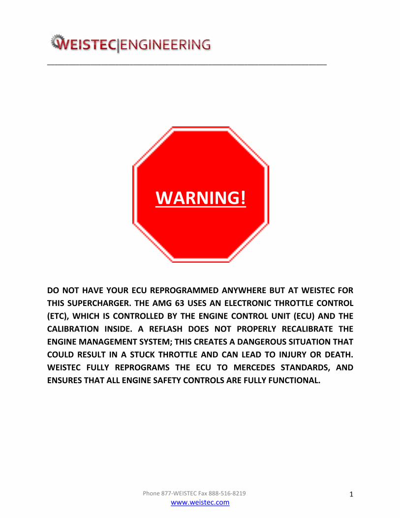
DO NOT HAVE YOUR ECU REPROGRAMMED ANYWHERE BUT AT WEISTEC FOR
THIS SUPERCHARGER. THE AMG 63 USES AN ELECTRONIC THROTTLE CONTROL
(ETC), WHICH IS CONTROLLED BY THE ENGINE CONTROL UNIT (ECU) AND THE
CALIBRATION INSIDE. A REFLASH DOES NOT PROPERLY RECALIBRATE THE
ENGINE MANAGEMENT SYSTEM; THIS CREATES A DANGEROUS SITUATION THAT
COULD RESULT IN A STUCK THROTTLE AND CAN LEAD TO INJURY OR DEATH.
WEISTEC FULLY REPROGRAMS THE ECU TO MERCEDES STANDARDS, AND
ENSURES THAT ALL ENGINE SAFETY CONTROLS ARE FULLY FUNCTIONAL.
WARNING!

______________________________________________________________________________
Phone 877-WEISTEC Fax 888-516-8219
www.weistec.com 2
THE WEISTEC M156 SUPERCHARGER AND ACCOMPANYING PROGRAMMING
ARE DESIGNED AROUND THE USE OF 91 OCTANE FUEL OR HIGHER ONLY.
BEFORE YOU RUN YOUR MERCEDES WITH THE WEISTEC M156 SUPERCHARGER
INSTALLED EVEN ONCE, YOU MUST EITHER DRAIN THE FUEL TANK COMPLETELY
AND FILL IT UP WITH 91 OCTANE, OR BEGIN USING 91 OCTANE IN YOUR
MERCEDES TWO COMPLETE FILLUPS BEFORE INSTALLATION.
WARNING!

______________________________________________________________________________
Phone 877-WEISTEC Fax 888-516-8219
www.weistec.com 3
IF YOU ARE NOT EXPERIENCED IN THE AREA OF
AUTOMOTIVE MECHANICS, WE STRONGLY URGE THAT
YOU REFER THIS INSTALLATION TO A CERTIFIED
INSTALLER OR TECHNICIAN.
WARNING!

______________________________________________________________________________
Phone 877-WEISTEC Fax 888-516-8219
www.weistec.com 4
THE WEISTEC M156 SUPERCHARGER MUST BE FILLED WITH
160 mL OF PROVIDED OIL PRIOR TO ROTATION OF THE
COMPRESSOR SCREW SYSTEM OR YOUR WARRANTY WILL BE
VOIDED.
WARNING!

______________________________________________________________________________
Phone 877-WEISTEC Fax 888-516-8219
www.weistec.com 5
WEISTEC M156 SUPERCHARGER Installation Guide for MERCEDES AMG 63
Thank you for your purchase of the Weistec M156 Supercharger for the Mercedes AMG 63 with the 6.3L motor. We appreciate your business, and we know you will enjoy your product. For your benefit, please read the following instructions completely and thoroughly before attempting to install the supercharger. Many questions we have received from customers about the installation of our products that could have been easily solved by information listed in the accompanying installation guide. We want you to enjoy the product in its fully functional state, and reading this tutorial is the first step to getting you on your way to a more rare and powerful Mercedes AMG. PLEASE NOTE THAT IF YOU HAVE ANY AFTERMARKET POWERTRAIN PARTS ALREADY INSTALLED ON YOUR VEHICLE, YOU MUST RETURN THE CAR TO STOCK STATUS – THIS INCLUDES PULLEYS, PROGRAMMING, ETC. THE CAR WILL NOT FUNCTION AND PARTS MAY NOT FIT PROPERLY IF OTHER AFTERMARKET PARTS ARE INSTALLED. We strongly urge that you also have at least one person to help you install the supercharger, as the unit is heavy. You will soon be on your way to installing the World's First Supercharger for the 6.3L! Again, thank you for choosing Weistec Engineering!

______________________________________________________________________________
Phone 877-WEISTEC Fax 888-516-8219
www.weistec.com 6
Table of Contents
Tools Required ............................................................................. Error! Bookmark not defined.
I. Disassembly ..................................................................................................................... 2
II. Bumper and Underbody Removal ............................................................................. 10
III. Cradle and Air Tube Delete ......................................................................................... 11
IV. Weistec M156 Supercharger Installation................................................................. 19
V. Power Steering Reservoir Relocation ....................................................................... 26
VI. 8 Rib Upgrade ................................................................................................................ 30
VII. Intercooler System Installation and Plumbing ....................................................... 66
VIII. Bumper and Underbody Installation ........................................................................ 75
IX. Fuel Injector Clips ......................................................................................................... 75
X. Supplementary Installation and Fluid Check .......................................................... 78

______________________________________________________________________________
Phone 877-WEISTEC Fax 888-516-8219
www.weistec.com 7
Tools Required
Hydraulic Jack or service lift
Jack Stands or transmission stand
1/4” Drive Ratchet
12" Long 1/4" Drive Extension
6.5mm 1/4” Drive Deep Well Socket
8mm 1/4” Drive Deep Well Socket
10mm 1/4” Drive Deep Well Socket
17mm 3.8" Drive Deep Well Socket
10mm Open End Wrench
13mm Open End Wrench
14mm Open End Wrench
15mm Open End Wrench
17mm Open End Wrench
1" Open End Wrench
8mm Ratcheting Wrench
3/8” Drive Ratchet
13mm 3/8" Drive Socket
16mm 3/8” Drive Deep Well Socket
Vice
17mm 3/8" Drive Deep Well Socket
19mm Heavy Duty Deep Well Socket
T-25 1/4" Drive Torx Bit
T‐30 1/4" or 3/8” Drive Torx Bit
T-45 3/8" Drive Torx Bit
T-50 3/8" Drive Torx Bit
E-8 3/8" Drive Reverse Torx Bit
E-10 3/8” Drive Reverse Torx Bit
E-14 3/8" Drive Reverse Torx Bit
Flat Head Screw Driver
Wire Cutter
Pushpin Removal Tool
6mm Drive Hex Bit
8mm Drive Hex Bit
Mechanics Rags
Vacuum
Painters Tape
Fluid evacuator

______________________________________________________________________________
Phone 877-WEISTEC Fax 888-516-8219
www.weistec.com 1
Impact Gun (Optional)
Crimp Style clamp tool
5mm Drill bit
Drill
Grinder (Optional)
Torque Wrench
______________________________________________________________________________
Phone 877-WEISTEC Fax 888-516-8219
www.weistec.com 2
I. Disassembly Before removing battery terminal, double check vehicle is in Park, and driver side window is
completely down.
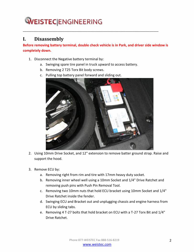
1. Disconnect the Negative battery terminal by:
a. Swinging spare tire panel in truck upward to access battery.
b. Removing 2 T25 Torx Bit body screws.
c. Pulling top battery panel forward and sliding out.
2. Using 10mm Drive Socket, and 12" extension to remove batter ground strap. Raise and
support the hood.
3. Remove ECU by:
a. Removing right from rim and tire with 17mm heavy duty socket.
b. Removing inner wheel well using a 10mm Socket and 1/4" Drive Ratchet and
removing push pins with Push Pin Removal Tool.
c. Removing two 10mm nuts that hold ECU bracket using 10mm Socket and 1/4"
Drive Ratchet inside the fender.
d. Swinging ECU and Bracket out and unplugging chassis and engine harness from
ECU by sliding tabs.
e. Removing 4 T-27 bolts that hold bracket on ECU with a T-27 Torx Bit and 1/4"
Drive Ratchet.

______________________________________________________________________________
Phone 877-WEISTEC Fax 888-516-8219
www.weistec.com 3
BEFORE MOVING ON, PLEASE FILL OUT THE VEHICLE INFORMATION/TUNE REQUEST FORM
AND MAIL THE ECU AND FORM TO 1701 E. EDINGER AVE. SUITE G4, SANTA ANA, CA 92705,
USA.
ELECTRONIC COMPONENTS SUCH AS THE ECU ARE VERY FRAGILE. PLEASE BE SURE TO
SECURELY PACK THE ECU WITH PROTECTIVE COVERING WHEN MAILING.
THE VEHICLE INFORMATION/TUNE REQUEST FORM IS INCLUDED WITH THE SUPERCHARGER
SYSTEM DOCUMENTATION, AND CAN ALSO BE FOUND AT http://weistec.com/support.html
4. Remove the air intake system from the vehicle by:
a. Removing plastic MAF clips.
b. Unplugging both MAF's.
c. Removing Mercedes engine cover.
d. Removing both air box inlet tubes.
e. Unplugging vacuum canister line.
f. Using Flat Head Screw Driver or 6.5mm Socket to loosen both Clamps.
g. Lifting the air box assemblies from the vehicle.
Place all removed parts in a safe location. Many parts will be reused.
5. Remove intake manifold by:
a. Disconnecting Vacuum line from canister above the intake plenum.

______________________________________________________________________________
Phone 877-WEISTEC Fax 888-516-8219
www.weistec.com 4
b. Removing stock Y inlet from rear section of intake manifold. (Retaining clips on
both side of Y must be lifted upwards)
c. Unplugging all sensor clips, hoses, and fasteners and make wire harness free for
removal.
8 injector clips
Rear IAT Sensor clip
Fuel pressure sensor clip
2 throttle body clips (Front of manifold)
1 map sensor clip (Front of manifold)
1 Variable runner clip (Front of manifold)
Air pump vacuum hose (Front of manifold, On solenoid side NOT
manifold side)
d. Removing EVAP line from rear left valve cover and EVAP Silonoid.
e. Removing Variable Runner Solenoid from Intake Manifold and storing it for
reinstallation during final installation.
f. Removing PCV hose with T25 TORX Bit.
g. Removing 4 bolts for fuel rail removal.
h. Disconnecting fuel line using 14mm Open End Wrench and 17mm Open End
Wrench.
MAP
Variable Runner
TB 2 TB 1

______________________________________________________________________________
Phone 877-WEISTEC Fax 888-516-8219
www.weistec.com 5
Please be aware that the fuel system may retain fuel pressure that can be extremely
dangerous if removed suddenly. Proceed with caution.
Please be aware of dripping fuel that may get on parts that can be affected. Please cover fuel
line with a shop rag in this case.
i. Removing 10 T-45 Torx bolts from intake manifold.
j. Lifting intake manifold and setting on work bench.
k. Vacuuming area near ports to collect all trapped dust and debris.
l. Removing intake manifold gaskets and placing painters tape on runners.
6. Remove power steering reservoir and bracket by:
a. Removing all fluid with the use of a fluid evacuator.
b. Removing T-25 Torx bolt from reservoir tab.
c. Lifting up and disconnecting 2 lines from the front of the engine. (Remove hard
lines with reservoir.)
d. Use rags to reduce spillage.
e. Disconnecting retaining clip for air pump solenoid.
f. Removing 4 T-45 bolts and eliminate engine bracket.
7. Remove both rear engine hoist brackets by:
a. Removing 3 T-45 Torx bolts from right side of vehicle.
b. Cutting harness zip tie from bracket and removing bracket.
c. Inserting 2 T-45 Torx bolts to hold dipstick tube to head. (Same location)
d. Removing 3 T-45 Torx bolts from left side of vehicle.
e. Removing bracket.
8. Remove Throttle bodies by:
a. Placing intake manifold on clean work bench.
b. Removing map sensor with T-30 Torx Bit. (2 Bolts)
c. Detaching wire harness from the front of the intake manifold.

______________________________________________________________________________
Phone 877-WEISTEC Fax 888-516-8219
www.weistec.com 6
d. Flipping manifold upside down, and removing 12 T-30 Torx bolts.
e. Inserting flat head screw driver between lower pan, and manifold plate and
gently prying to open.
T-30

______________________________________________________________________________
Phone 877-WEISTEC Fax 888-516-8219
www.weistec.com 7
f. Pulling rubber wire bulk head through hole.
g. Using T-30 Torx bit, and removing 4 bolts per throttle body, and 2 metal wire
clamps.
h. Removing evaporative lines from each throttle body, as well as both horns by
unclipping from the side.
i. Bolting complete assembly back together to ensure safe storage.
______________________________________________________________________________
Phone 877-WEISTEC Fax 888-516-8219
www.weistec.com 8
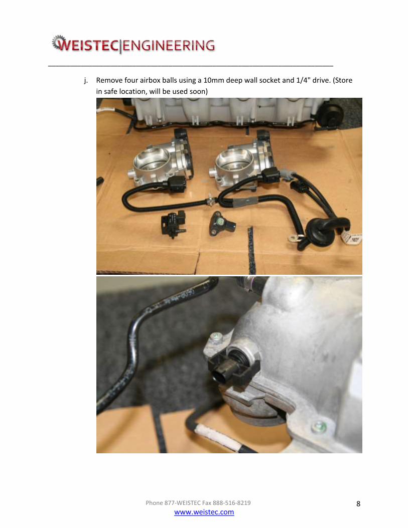
j. Remove four airbox balls using a 10mm deep wall socket and 1/4" drive. (Store
in safe location, will be used soon)

______________________________________________________________________________
Phone 877-WEISTEC Fax 888-516-8219
www.weistec.com 9
At this point you will need to gather two (2) throttle bodies, two (2) throttle body gaskets,
one (1) throttle body harness, one (1) runner solenoid, one (1) map sensor, and one (1) IAT
Sensor. These items will be reused on the supercharger system.
______________________________________________________________________________
Phone 877-WEISTEC Fax 888-516-8219
www.weistec.com 10
II. Bumper and Underbody Removal 1. Safely place vehicle on vehicle hoist or stands.
2. Remove belly pan, and bumper shrouds by:
a. Using 8mm Socket and 1/4" Drive to remove complete underbody and set in a
safe location.
b. Using Push Pin Removal Tool, remove five pins from left and right side wheel
well and underbody. (Total varies on build date.)
c. Removing turn signal light on left and right side of bumper.
d. Using an 8mm Ratcheting Wrench, remove both bolts inside Signal hole.
e. Using 8mm Socket, 12" long 1/4" extension, and 1/4" Drive, remove top bumper
bolts between headlight mount and grill.
f. Removing grill support using 8mm Socket from radiator support.
g. Pulling both side grills from the bottom of the bumper to gain access.
h. Using 8mm Socket, 12" long 1/4" extension, and 1/4" Drive, remove bolt from
either side of lower grill in corner.
i. With the help of one more person, slide bumper forward and disconnect
headlight sprayers.
j. Setting bumper in a safe location.
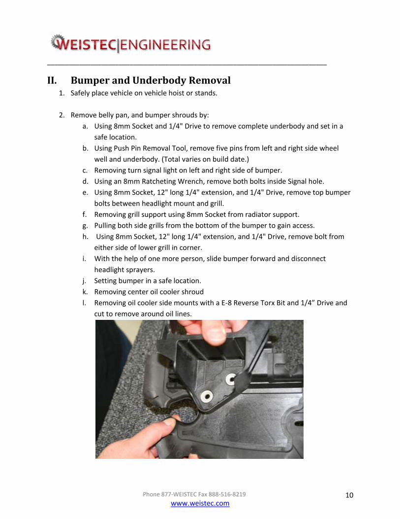
k. Removing center oil cooler shroud
l. Removing oil cooler side mounts with a E-8 Reverse Torx Bit and 1/4” Drive and
cut to remove around oil lines.

______________________________________________________________________________
Phone 877-WEISTEC Fax 888-516-8219
www.weistec.com 11
Shrouding and oil cooler side mounts (above) will be completely removed from vehicle at this
point.
Oil cooler will be mounted to heat exchanger in steps ahead.
III. Cradle and Air Tube Delete
______________________________________________________________________________
Phone 877-WEISTEC Fax 888-516-8219
www.weistec.com 12
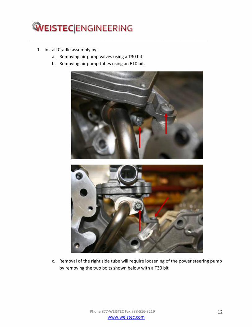
1. Install Cradle assembly by:
a. Removing air pump valves using a T30 bit
b. Removing air pump tubes using an E10 bit.
c. Removal of the right side tube will require loosening of the power steering pump
by removing the two bolts shown below with a T30 bit

______________________________________________________________________________
Phone 877-WEISTEC Fax 888-516-8219
www.weistec.com 13
______________________________________________________________________________
Phone 877-WEISTEC Fax 888-516-8219
www.weistec.com 14
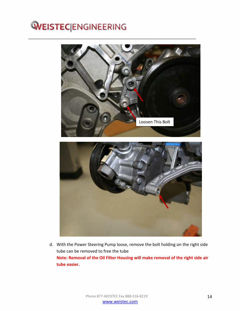
d. With the Power Steering Pump loose, remove the bolt holding on the right side
tube can be removed to free the tube
Note: Removal of the Oil Filter Housing will make removal of the right side air
tube easier.
Loosen This Bolt
______________________________________________________________________________
Phone 877-WEISTEC Fax 888-516-8219
www.weistec.com 15
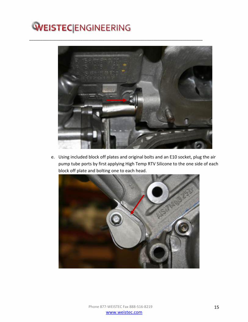
e. Using included block off plates and original bolts and an E10 socket, plug the air
pump tube ports by first applying High Temp RTV Silicone to the one side of each
block off plate and bolting one to each head.

______________________________________________________________________________
Phone 877-WEISTEC Fax 888-516-8219
www.weistec.com 16
f. Bolt the Power Steering pump back on
g. Cleaning block surface where existing power steering reservoir mounted.
h. Positioning the cradle in the same location as the stage 1/1+ cradle
i. Insert two M8x1.25x25mm bolts through the top of the cradle and partially
thread them. Do not tighten the bolts yet

______________________________________________________________________________
Phone 877-WEISTEC Fax 888-516-8219
www.weistec.com 17
j. Bolt on Belt Wrap Idler using the M8x1.25x90mm bolts to the front of the cradle.
Partially thread them in.
Installation of
the belt wrap
idler is shown in
this illustration
Insert bolt into this hole. A bolt is
not used in the other hole to make
servicing the supercharger in the
future easier.

______________________________________________________________________________
Phone 877-WEISTEC Fax 888-516-8219
www.weistec.com 18
k. Tighten all four bolts using a 6mm hex bit starting with the top bolts then tighten
the front bolts. Apply Red Loctite and torque to 20 ft-lbs
l. Removing existing serpentine belt using a 17mm 3/8" deep socket and a 3/8"
drive onto belt tensioner.

______________________________________________________________________________
Phone 877-WEISTEC Fax 888-516-8219
www.weistec.com 19
IV. Weistec M156 Supercharger Installation
Always keep your work area clean for this process.
1. Install Supercharger System by:
a. Removing Supercharger from Box A and clean and dust or debris from system.
b. Removing runner cover tags, and all vacuum port plastic covers. Do NOT remove
throttle body covers.
c. Removing painters tape from ports and double check a clean surface.
d. Placing new (Included) intake manifold gaskets on head surface.
e. Clocking water manifold ports (Rear of Supercharger system) at a 10 o'clock and
2 o'clock position. (Do not tighten clamping bolts until you are sure water lines
will clear near firewall)
f. Installing the following vacuum lines before installation:
Air pump vacuum line on lowest vacuum port for Stage 1 and Stage 2
vehicles, For Stage 3 the 1/8” port must be securely plugged or capped
Long 3/8" EVAP line. (Keep coiled on top of supercharger unit)
10" 1/2" brake boost line with crimp style clamp.
______________________________________________________________________________
Phone 877-WEISTEC Fax 888-516-8219
www.weistec.com 20
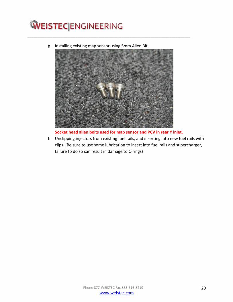
g. Installing existing map sensor using 5mm Allen Bit.
Socket head allen bolts used for map sensor and PCV in rear Y inlet.
h. Unclipping injectors from existing fuel rails, and inserting into new fuel rails with
clips. (Be sure to use some lubrication to insert into fuel rails and supercharger,
failure to do so can result in damage to O rings)
______________________________________________________________________________
Phone 877-WEISTEC Fax 888-516-8219
www.weistec.com 21
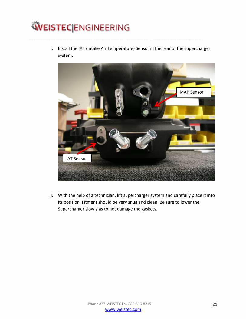
i. Install the IAT (Intake Air Temperature) Sensor in the rear of the supercharger
system.
j. With the help of a technician, lift supercharger system and carefully place it into
its position. Fitment should be very snug and clean. Be sure to lower the
Supercharger slowly as to not damage the gaskets.
MAP Sensor
IAT Sensor

______________________________________________________________________________
Phone 877-WEISTEC Fax 888-516-8219
www.weistec.com 22
k. Using the included new stainless socket Allen bolts, insert all ten and tighten
snug. Torque bolts in a start pattern to 18-19 Lb. Ft. (25 Nm)
l. Twisting existing brake booster line towards supercharger unit, and placing
included crimp style clamp on 1/2" brake booster hose and slide over existing
line. Adjust line and double check no bottle necks in line. Crimp clamp at this
point.
m. Installing new fuel rails and injectors onto supercharger unit buy using 4mm
Allen bit and 1/4" drive. Aluminum finish spacers will be used between manifold
and fuel rail.

______________________________________________________________________________
Phone 877-WEISTEC Fax 888-516-8219
www.weistec.com 23
n. Running new fuel line crossover behind Y inlet. (45° end must be on right side of
vehicle)
o. Using 7/8" wrench, tight both fuel line ends.
p. Replacing existing harness zip ties with included zip ties. Cut excess and dispose.
q. Carefully cutting 3 wire map sensor wire about 1.5" away from plug and crimping
new extension. Use included heat shrink on all crimp joints and be sure to have
no wiring or metal showing through. Use 3/8" heat shrink over all three wires.
Clip plug in rear of Y inlet.
Cut MAP sensor
plug here and
extend

______________________________________________________________________________
Phone 877-WEISTEC Fax 888-516-8219
www.weistec.com 24
r. Clipping existing throttle body harness. (Two plugs)
s. Plugging in Variable Runner and Air Pump Solenoids to the engine harness.
Variable Runner Solenoid will have no vacuum lines connected to it. Air Pump
Solenoid will re-use factory vacuum lines for Stage 1 and Stage 2 cars. Stage 3
cars the solenoid will only be plugged into the engine harness. Cable ties
should be used to secure the solenoid in place.
New MAP Sensor
Plug Location
Solenoid Cable
tied to harness
under air box

______________________________________________________________________________
Phone 877-WEISTEC Fax 888-516-8219
www.weistec.com 25
t. Installing existing PCV line in rear section of Y Inlet using a 5mm Allen key.
Twisting hose can be necessary for proper seal.
Shown Above is the PCV hose correctly positioned for installation.
u. Installing existing airbox balls on included stand-off's using a 10mm open end
wrench, and a 10mm deep wall socket and 1/4" drive.
v. Running 3/8" EVAP hose along coil pack wiring harness and using crimp style
clamp onto EVAP solenoid. Use included zip ties to hold in place of existing EVAP
line.

______________________________________________________________________________
Phone 877-WEISTEC Fax 888-516-8219
www.weistec.com 26
V. Power Steering Reservoir Relocation
1. Install included power steering reservoir by:
a. Removing two existing timing cover bolts (Remove Only The Two Bolts
Indicated Below) on right side using a T-30 Torx bit.
b. Removing wire harness bracket on right side.
c. Installing included 3/8" and 5/8" barb and fasten clamps using crimp style clamp
tool on factory hose side.
d. Installing included 3/8" and 5/8" hydraulic hose and fasten clamps using crimp
style clamp tool. (Technician will have to tailor line to vehicle. Line is typically a
couple inches long.)
Remove
______________________________________________________________________________
Phone 877-WEISTEC Fax 888-516-8219
www.weistec.com 27
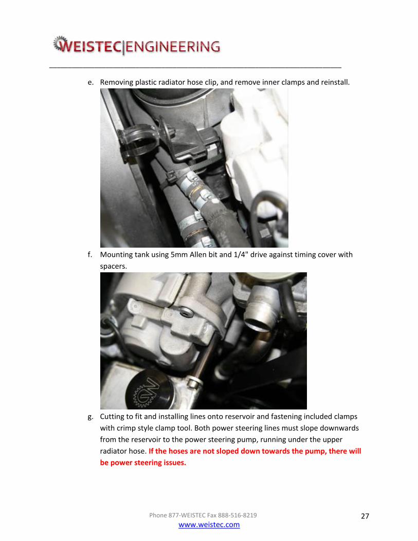
e. Removing plastic radiator hose clip, and remove inner clamps and reinstall.
f. Mounting tank using 5mm Allen bit and 1/4" drive against timing cover with
spacers.
g. Cutting to fit and installing lines onto reservoir and fastening included clamps
with crimp style clamp tool. Both power steering lines must slope downwards
from the reservoir to the power steering pump, running under the upper
radiator hose. If the hoses are not sloped down towards the pump, there will
be power steering issues.

______________________________________________________________________________
Phone 877-WEISTEC Fax 888-516-8219
www.weistec.com 28
h. Using cable ties against plastic radiator hose clip.

______________________________________________________________________________
Phone 877-WEISTEC Fax 888-516-8219
www.weistec.com 29
WARNING! Improper routing of lines can result in damage to power steering components or
fire. Double check all lines slope down towards the pump from the reservoir and are free and
clear of moving parts. Take extra precaution. Fill reservoir with OEM fluid. Power Steering
System must be properly bled to ensure proper operation and prevent damage to
components. Bleeding instructions can be found in the Supplementary section of this install
manual.

______________________________________________________________________________
Phone 877-WEISTEC Fax 888-516-8219
www.weistec.com 30
VI. 8 Rib Upgrade 2. Install 8 Rib Upgrade by:
m. Removing existing serpentine belt using a 17mm 3/8" deep socket and a 3/8"
drive onto belt tensioner.
ALL BILLET 8 RIB IDLERS MUST BE INSTALLED WITH THE LOCKING
RING FACING THE RADIATOR
65mm Idler
Grooved Idler
Alternator Pulley
54mm Idler
Tensioner
Idler
Water Pump
Pulley
Crank Pulley
Not Used, If Your Vehicle
Has This Idler Remove It
AC Pulley
Power
Steering
Pulley
Supercharger
Pulley
65mm Idler
Installed in
Previous Steps
DO NOT ALTER
______________________________________________________________________________
Phone 877-WEISTEC Fax 888-516-8219
www.weistec.com 31
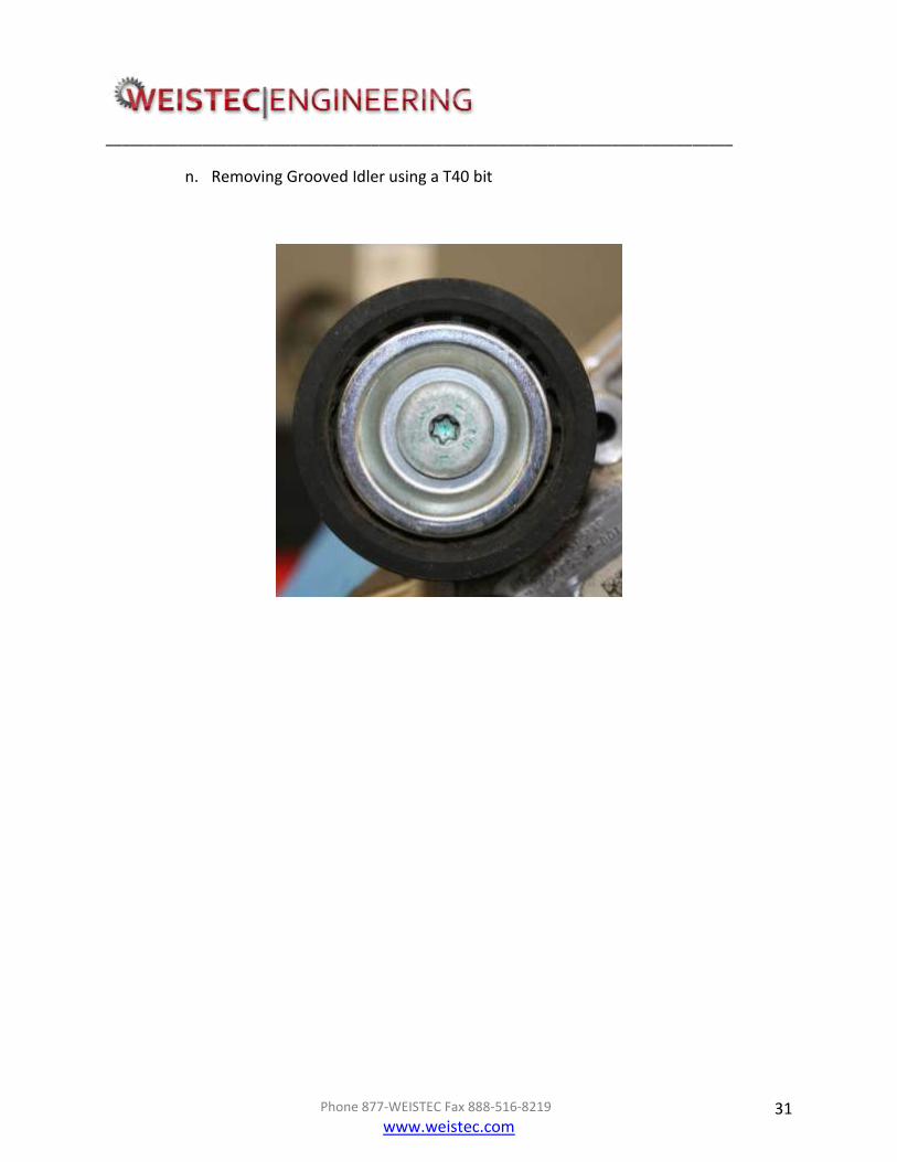
n. Removing Grooved Idler using a T40 bit

______________________________________________________________________________
Phone 877-WEISTEC Fax 888-516-8219
www.weistec.com 32
o. Bolting on 8 Rib Grooved Idler using the provided M8x1.25x40 bolt and M8
Bearing washer with a 6mm hex bit. Apply red Loctite to bolt before Installation
and torque to 31.5nm

______________________________________________________________________________
Phone 877-WEISTEC Fax 888-516-8219
www.weistec.com 33
p. Removing 65mm Idler using a T40 bit

______________________________________________________________________________
Phone 877-WEISTEC Fax 888-516-8219
www.weistec.com 34
q. Bolting on 8 Rib Double Bearing Idler using the provided M8x1.25x40 bolt and
bearing washer with a 6mm hex bit. Apply red Loctite to bolt before Installation
and torque to 31.5nm

______________________________________________________________________________
Phone 877-WEISTEC Fax 888-516-8219
www.weistec.com 35
r. Removing 54mm Idler using an E12 socket. Bearing bushing on the back side of
the 54mm Idler will be reused
______________________________________________________________________________
Phone 877-WEISTEC Fax 888-516-8219
www.weistec.com 36
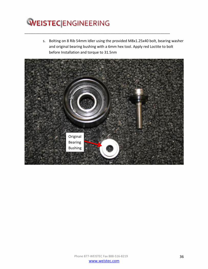
s. Bolting on 8 Rib 54mm Idler using the provided M8x1.25x40 bolt, bearing washer
and original bearing bushing with a 6mm hex tool. Apply red Loctite to bolt
before Installation and torque to 31.5nm
Original
Bearing
Bushing

______________________________________________________________________________
Phone 877-WEISTEC Fax 888-516-8219
www.weistec.com 37
Original
Bearing
Bushing

______________________________________________________________________________
Phone 877-WEISTEC Fax 888-516-8219
www.weistec.com 38
.

______________________________________________________________________________
Phone 877-WEISTEC Fax 888-516-8219
www.weistec.com 39
t. Removing 76mm Tensioner Pulley using a T40 bit and removing the factory belt
tensioner
______________________________________________________________________________
Phone 877-WEISTEC Fax 888-516-8219
www.weistec.com 40
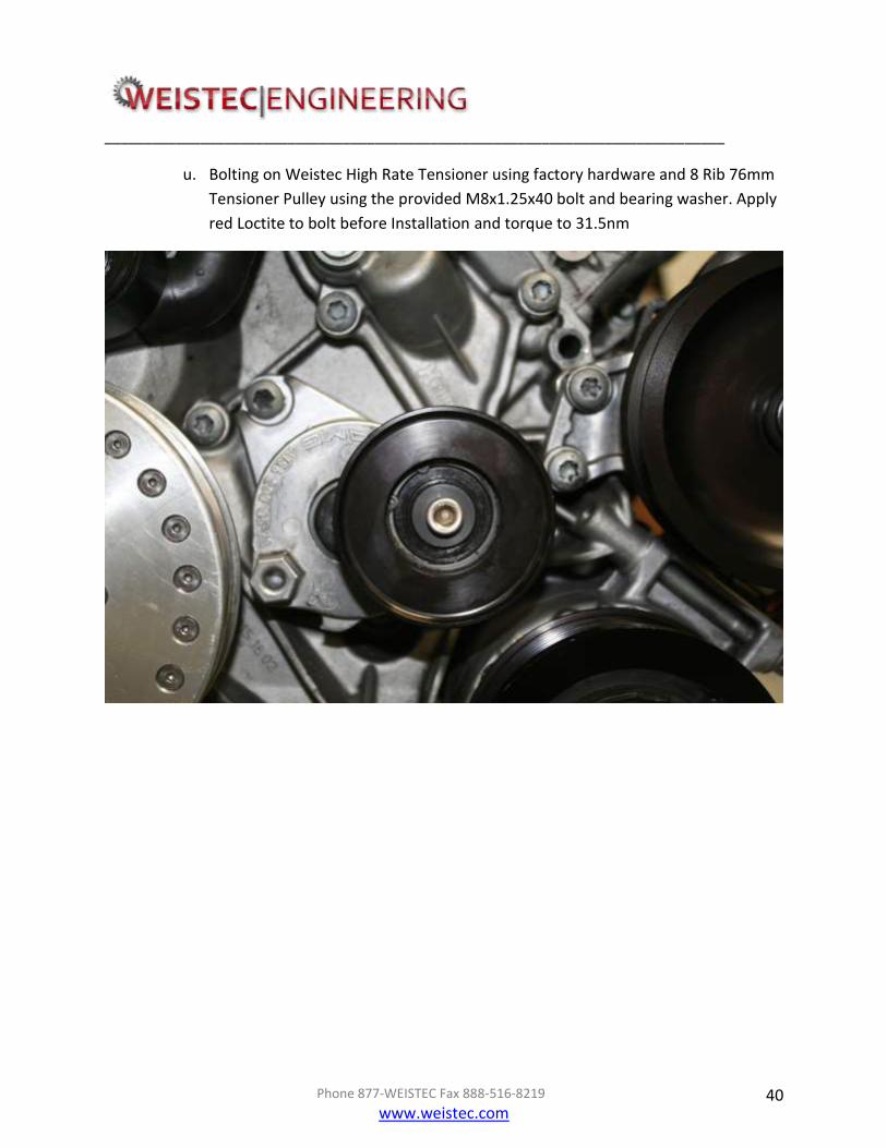
u. Bolting on Weistec High Rate Tensioner using factory hardware and 8 Rib 76mm
Tensioner Pulley using the provided M8x1.25x40 bolt and bearing washer. Apply
red Loctite to bolt before Installation and torque to 31.5nm
______________________________________________________________________________
Phone 877-WEISTEC Fax 888-516-8219
www.weistec.com 41
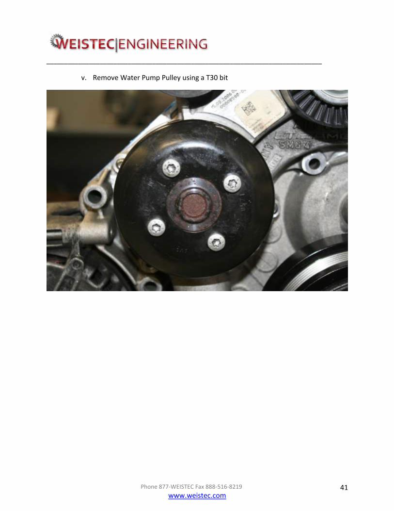
v. Remove Water Pump Pulley using a T30 bit

______________________________________________________________________________
Phone 877-WEISTEC Fax 888-516-8219
www.weistec.com 42
w. Bolting on 8 Rib Water Pump Pulley using the 4 M6x1x12 bolts provided. Apply
red Loctite to bolt before Installation and torque to 12.5nm

______________________________________________________________________________
Phone 877-WEISTEC Fax 888-516-8219
www.weistec.com 43
x. Remove alternator pulley by using a 22mm 6 point socket and an impact gun

______________________________________________________________________________
Phone 877-WEISTEC Fax 888-516-8219
www.weistec.com 44
y. Bolting on 8 Rib Alternator Pulley using the original 22mm nut. Apply red Loctite
to threads on alternator shaft before Installation

______________________________________________________________________________
Phone 877-WEISTEC Fax 888-516-8219
www.weistec.com 45
The Immediate Following Steps are for Vehicles with Version 1 and Version 3
AC Pulleys. For Version 2 AC Pulley, Skip To Step w
z. Removing AC Pulley using the supplied AC Pulley tool and a 1/4” drive 7mm deep
socket with the socket wrench set to TIGHTEN/CLOCKWISE. Take care with this
step as it is possible to damage the threads/bolt and make the AC Pulley Hub
unusable. It helps to wrap the belt around the AC Pulley and then the crank
pulley to keep the AC pulley from turning.

______________________________________________________________________________
Phone 877-WEISTEC Fax 888-516-8219
www.weistec.com 46
aa. Using pick tools and a small flat head screwdriver, remove the snap ring from the
AC Pulley. Take care to not bend or break the snap ring as it will be reused
______________________________________________________________________________
Phone 877-WEISTEC Fax 888-516-8219
www.weistec.com 47
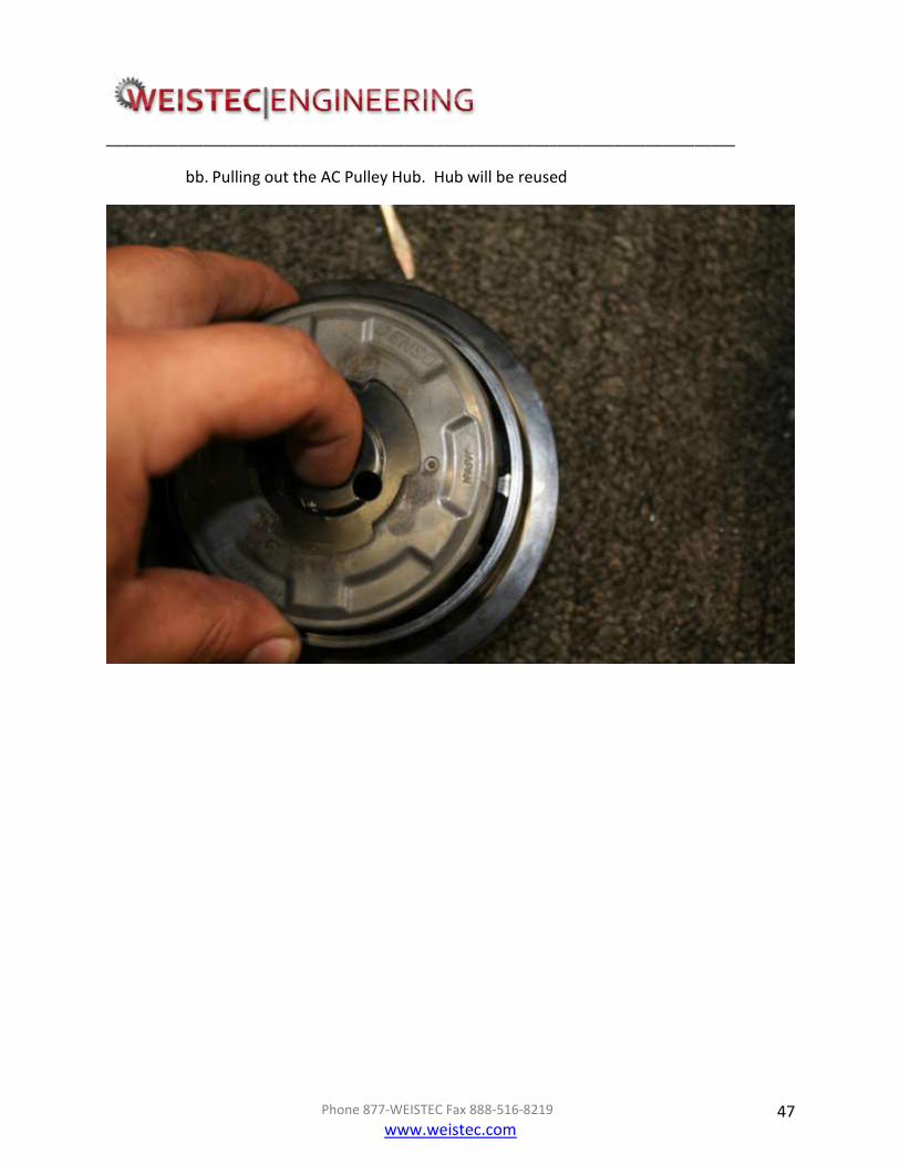
bb. Pulling out the AC Pulley Hub. Hub will be reused
______________________________________________________________________________
Phone 877-WEISTEC Fax 888-516-8219
www.weistec.com 48
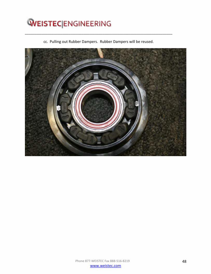
cc. Pulling out Rubber Dampers. Rubber Dampers will be reused.
______________________________________________________________________________
Phone 877-WEISTEC Fax 888-516-8219
www.weistec.com 49
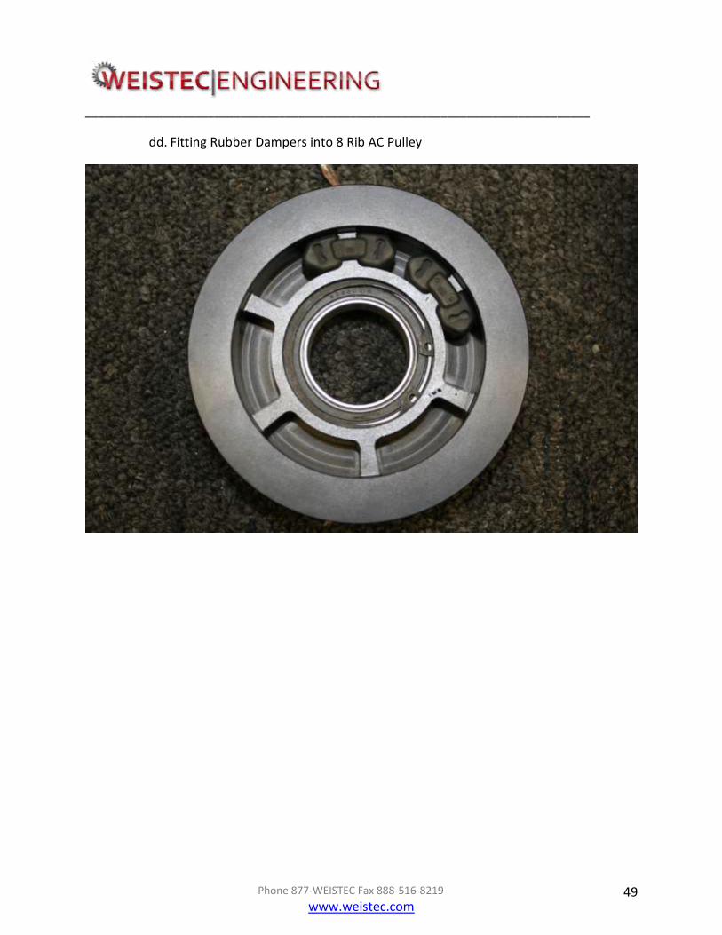
dd. Fitting Rubber Dampers into 8 Rib AC Pulley

______________________________________________________________________________
Phone 877-WEISTEC Fax 888-516-8219
www.weistec.com 50

______________________________________________________________________________
Phone 877-WEISTEC Fax 888-516-8219
www.weistec.com 51
ee. Pressing on AC Pulley Hub

______________________________________________________________________________
Phone 877-WEISTEC Fax 888-516-8219
www.weistec.com 52
ff. Locking in Snap Ring using a small flat head screwdriver and pick tools
______________________________________________________________________________
Phone 877-WEISTEC Fax 888-516-8219
www.weistec.com 53
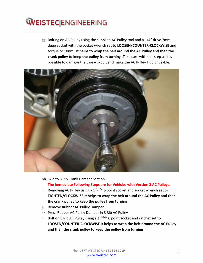
gg. Bolting on AC Pulley using the supplied AC Pulley tool and a 1/4” drive 7mm
deep socket with the socket wrench set to LOOSEN/COUNTER-CLOCKWISE and
torque to 10nm. It helps to wrap the belt around the AC Pulley and then the
crank pulley to keep the pulley from turning .Take care with this step as it is
possible to damage the threads/bolt and make the AC Pulley Hub unusable.
hh. Skip to 8 Rib Crank Damper Section
The Immediate Following Steps are for Vehicles with Version 2 AC Pulleys.
ii. Removing AC Pulley using a 1 1/16” 6 point socket and socket wrench set to
TIGHTEN/CLOCKWISE It helps to wrap the belt around the AC Pulley and then
the crank pulley to keep the pulley from turning
jj. Remove Rubber AC Pulley Damper
kk. Press Rubber AC Pulley Damper in 8 Rib AC Pulley
ll. Bolt on 8 Rib AC Pulley using a 1 1/16” 6 point socket and ratchet set to
LOOSEN/COUNTER-CLOCKWISE It helps to wrap the belt around the AC Pulley
and then the crank pulley to keep the pulley from turning

______________________________________________________________________________
Phone 877-WEISTEC Fax 888-516-8219
www.weistec.com 54
mm. Remove power steering pulley using an appropriate power steering
pulley tool

______________________________________________________________________________
Phone 877-WEISTEC Fax 888-516-8219
www.weistec.com 55
nn. Pressing on the 8 Rib Power Steering Pulley using a power steering pulley tool
(not included). The pulley must be installed with the grooved center section
facing the radiator. Be sure to check alignment of the pulley as you are
pressing it on. Press pulley on until the ribs are lined up with the ribs on the AC
Pulley, poor alignment will cause belt issues.
oo. Bolting on supplied bolt and washer. Apply Loctite 609 Retaining Compound to
the threads of the bolt before installing and torque to 31.5nm
This part of the 8 Rib
Power Steering Pulley
must face the radiator
Use a wrench to
hold this nut
Use a wrench or
socket to tighten
this bolt to pull off
the pulley

______________________________________________________________________________
Phone 877-WEISTEC Fax 888-516-8219
www.weistec.com 56
pp.
Install 8 Rib Crank Damper by:
This Section Will Require Removal Of The Radiator Fan And Possibly The
Assistance Of A Second Technician. Removal Of The Entire Radiator Is
Recommended To Provide Extra Working Room.
a. Removing the cover of the transmission diagnostic port located on the
transmission bell housing, opposite to the starter.
b. Using a Mercedes Flywheel lock, lock the flywheel in place (The flywheel may be
locked with a pry bar, the second technician must lock the flywheel in place to
allow removal of the Crank Pulley Bolt. It is highly recommended that the
Mercedes Flywheel Lock be used )
c. Removing Crank Pulley Bolt using a 1 1/16” 6 point socket and a large Breaker Bar.
If not using the Mercedes Flywheel Lock, Once the Crank Pulley Bolt has been
removed, have the second technician release the flywheel

______________________________________________________________________________
Phone 877-WEISTEC Fax 888-516-8219
www.weistec.com 57

______________________________________________________________________________
Phone 877-WEISTEC Fax 888-516-8219
www.weistec.com 58
d. Using a pry bar, slowly pry off the Crank Pulley. Work slowly on this step to
avoid damage and injury. A mallet may be used to help loosen the Crank Pulley
A video of the crank drilling process can be seen here:
https://www.youtube.com/watch?v=LpZpdJojDoQ
e. Bolting on Crank Drill Tool with included M16x1.5x100 bolt. Be sure that the
keyway is lined up properly and that the Crank Drill Tool freely slides all the way
on to the crank before screwing in the bolt. Torque bolt to 25nm with a 24mm
socket

______________________________________________________________________________
Phone 877-WEISTEC Fax 888-516-8219
www.weistec.com 59
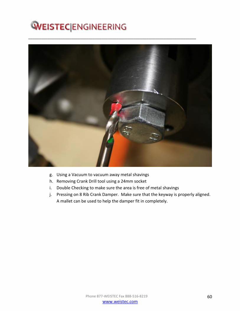
f. Applying grease or oil to the provided 7/32” drill bit and drilling the crank
through the two holes in the Crank Drill Tool. Drill into crank until the red
marking reaches the Crank Drill Tool as shown below. Perform drilling slowly to
avoid over heating or breaking of the drill bit. Stop drilling intermittently to
clean shavings off of drill bit and apply more grease/oil.
______________________________________________________________________________
Phone 877-WEISTEC Fax 888-516-8219
www.weistec.com 60
g. Using a Vacuum to vacuum away metal shavings
h. Removing Crank Drill tool using a 24mm socket
i. Double Checking to make sure the area is free of metal shavings
j. Pressing on 8 Rib Crank Damper. Make sure that the keyway is properly aligned.
A mallet can be used to help the damper fit in completely.

______________________________________________________________________________
Phone 877-WEISTEC Fax 888-516-8219
www.weistec.com 61

______________________________________________________________________________
Phone 877-WEISTEC Fax 888-516-8219
www.weistec.com 62
k. Using long pliers, insert the two steel dowel pins into the holes, ONE DOWEL PIN
IN EACH HOLE, then press them in until they are all the way in the holes.
l. Bolting in the included 8 Rib Crank Damper Bolt. Using a 1 1/16” 6 point socket
torque the bolt to 250nm then turn the bolt an additional 90 degrees (if not
using Mercedes Flywheel Lock, With a pry bar, the second technician must lock
the flex plate in place to allow tightening of the 8 Rib Crank Damper Bolt.

______________________________________________________________________________
Phone 877-WEISTEC Fax 888-516-8219
www.weistec.com 63
______________________________________________________________________________
Phone 877-WEISTEC Fax 888-516-8219
www.weistec.com 64
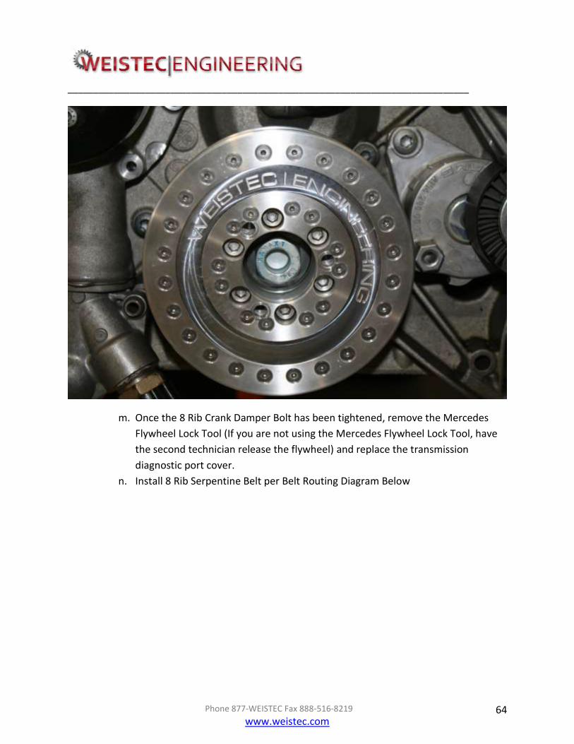
m. Once the 8 Rib Crank Damper Bolt has been tightened, remove the Mercedes
Flywheel Lock Tool (If you are not using the Mercedes Flywheel Lock Tool, have
the second technician release the flywheel) and replace the transmission
diagnostic port cover.
n. Install 8 Rib Serpentine Belt per Belt Routing Diagram Below

______________________________________________________________________________
Phone 877-WEISTEC Fax 888-516-8219
www.weistec.com 65

______________________________________________________________________________
Phone 877-WEISTEC Fax 888-516-8219
www.weistec.com 66
VII. Intercooler System Installation and Plumbing
1. Remove right front headlight by:
a. Using 8mm socket, 12" extension, and 1/4" drive, remove bolt from top of head
light and both sides.
b. Unplugging electrical clips from the back side of the headlight.
2. Install Intercooler recovery tank by(Skip this Section if installing Weistec Trunk Ice
Tank, Refer to Trunk Tank Manual for hose routing):
a. Removing and unplugging horn using 13mm socket and 3/8" drive.
b. Removing existing fender bolts using a 10mm socket and 1/4" drive, and
inserting new longer bolts using 10mm socket and 1/4" drive. (Remove and
install one bolt a time to insure no misalignment of the fender.)
c. Installing recovery tank onto recovery tank bracket using a 10mm Socket and
1/4" Drive. (Three bolts total)

______________________________________________________________________________
Phone 877-WEISTEC Fax 888-516-8219
www.weistec.com 67
d. Installing existing horn on ear of bracket using a 10mm Socket and 1/4" Drive.
e. Installing complete assembly by sliding bracket onto bolts under fender and
clamping with the included flange nuts using a 10mm Socket and 1/4" Drive.
3. Install Water Pump by:
a. Removing existing bumper beam support bolts using a 10mm Socket and 1/4"
Drive.
b. Rotating horn 90 deg counter-clockwise.
c. Removing existing bumper beam support bolts using a 10mm Socket and 1/4"
Drive.
d. Installing included longer support bolts using a 10mm Socket and 1/4" Drive.
e. Removing water pump from original box, and installing it on water pump bracket
using a 13mm Open Ended Wrench, and the included body bolts.
f. Using a 10mm Socket and 1/4" Drive install water pump assembly with included
flange nuts.

______________________________________________________________________________
Phone 877-WEISTEC Fax 888-516-8219
www.weistec.com 68
4. Install Heat Exchanger by:
a. Using a 5mm Drill Bit and a Drill, drill four holes on marks through bumper
support.
b. Using four included body bolts, use an 8mm Socket and 1/4" drive to screw in
place.
______________________________________________________________________________
Phone 877-WEISTEC Fax 888-516-8219
www.weistec.com 69
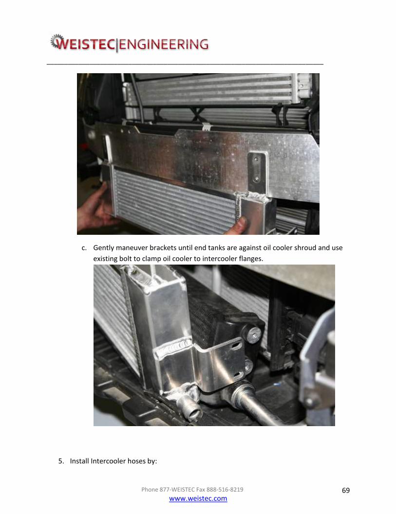
c. Gently maneuver brackets until end tanks are against oil cooler shroud and use
existing bolt to clamp oil cooler to intercooler flanges.
5. Install Intercooler hoses by:

______________________________________________________________________________
Phone 877-WEISTEC Fax 888-516-8219
www.weistec.com 70
a. Placing included clamps on both ends of S-Shaped molded hose and installing
from the heat exchanger to the water pump.
b. Placing included clamps on both ends of complex shaped molded hose and
installing from heat exchanger to the bottom of the recovery tank.
______________________________________________________________________________
Phone 877-WEISTEC Fax 888-516-8219
www.weistec.com 71
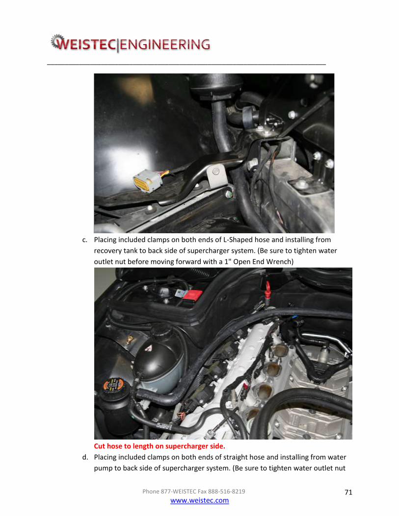
c. Placing included clamps on both ends of L-Shaped hose and installing from
recovery tank to back side of supercharger system. (Be sure to tighten water
outlet nut before moving forward with a 1" Open End Wrench)
Cut hose to length on supercharger side.
d. Placing included clamps on both ends of straight hose and installing from water
pump to back side of supercharger system. (Be sure to tighten water outlet nut

______________________________________________________________________________
Phone 877-WEISTEC Fax 888-516-8219
www.weistec.com 72
before moving forward with a 1" Open End Wrench)
Cut hose to length on supercharger side.
Double Check all fitments of hoses and assure no bottle neck or kink in hose.
This will greatly reduce flow and performance of system. Also double check all
hoses are not lying against sharp objects.
6. Install Water Pump Wiring by:
______________________________________________________________________________
Phone 877-WEISTEC Fax 888-516-8219
www.weistec.com 73
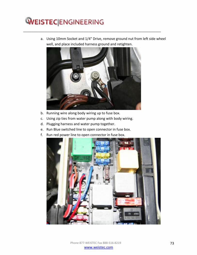
a. Using 10mm Socket and 1/4" Drive, remove ground nut from left side wheel
well, and place included harness ground and retighten.
b. Running wire along body wiring up to fuse box.
c. Using zip ties from water pump along with body wiring.
d. Plugging harness and water pump together.
e. Run Blue switched line to open connector in fuse box.
f. Run red power line to open connector in fuse box.

______________________________________________________________________________
Phone 877-WEISTEC Fax 888-516-8219
www.weistec.com 74

______________________________________________________________________________
Phone 877-WEISTEC Fax 888-516-8219
www.weistec.com 75
VIII. Bumper and Underbody Installation 1. Install Bumper by:
a. Replugging all head light electrical clips.
b. Reinstalling bumper cover using an 8mm Socket, 12" Extension, 1/4" Drive and
8mm Ratcheting Wrench.
c. Reinstall grill support using a 8mm Socket and 1/4" Drive onto radiator support.
d. Lift car on hoist and reinstall underbody using an 8mm Socket and 1/4" Drive and
reinserting all push pins. (Ten total)
e. Reinstall front wheels using a 17mm Deep Wall Socket and Torque Wrench.
Torque to 90 Lb. Ft. (122 Nm)
IX. Fuel Injector Clips

______________________________________________________________________________
Phone 877-WEISTEC Fax 888-516-8219
www.weistec.com 76
a. Cutting eight factory injector pigtails with a Wire Cutting Tool.
b. Replacing factory pigtail with supplied injector pigtail, using Crimping Pliers
against supplied butt-connector.
Cut Here
Strip wiring insulation

______________________________________________________________________________
Phone 877-WEISTEC Fax 888-516-8219
www.weistec.com 77
c. Securely connecting new injector clips to High Capacity Fuel Injectors
Crimp both
ends here
Slide heat shrink
before crimping.
Use heat gun to
shrink.

______________________________________________________________________________
Phone 877-WEISTEC Fax 888-516-8219
www.weistec.com 78
X. Supplementary Installation and Fluid Check
1. Install existing fuel line by:
a. Removing line from existing fuel rails with a 17mm Open End Wrench.
b. Installing onto new fuel rails using a 17mm Open End Wrench on the fuel rail
side, and install onto chassis side using a 17mm Open End Wrench and 14mm
Open End Wrench.
2. Install Throttle Bodies by:
a. Placing throttle bodies in vice.
b. Tapping existing hole with supplied 1/8" NPT Tap.

______________________________________________________________________________
Phone 877-WEISTEC Fax 888-516-8219
www.weistec.com 79
c. using pipe sealant, place NPT plug into hole.
d. Removing protective film from throttle body inlets.
e. Placing included bolts into throttle body with existing gasket and fastening in star
formation on both sides.
f. Run existing throttle body wiring behind supercharger Y inlet and plug into both
throttle bodies.
3. Install factory air boxes by:
a. Installing included black couplers and clamps on throttle body side.
b. Fastening clamps on throttle body side.
c. Freely placing existing air box couplers over coupler, install factory air boxes.
d. Fasten clamps on air box side.
e. Install air box inlets.
4. Install ECU by:
a. Inserting ECU into the fixture.
b. Clipping Chassis and engine harness and sliding clips to ensure proper plug in.
c. Reinstalling onto bracket and sliding in fender.
d. Gently bolting it down with 10mm Socket and 1/4" Drive Ratchet.

______________________________________________________________________________
Phone 877-WEISTEC Fax 888-516-8219
www.weistec.com 80
5. Final assembly:
a. Plug in electrical connections for the Variable Runner Solenoid and Air Injection
Solenoid. Solenoids must be plugged in to prevent check engine lights and
other issues. Position solenoids in secure locations on the intake manifold and
use cable ties to hold them in place
b. Add water into intercooler system and double check no leaks.
c. Reinstall battery ground using a 10mm Socket and 1/4" Drive.
d. Reinstall battery cover.
e. Check all vital fluids.
f. Turn Key to on position and add water into intercooler system until system is
fully bled and water is visibly circulating.
6. Fill supercharger with oil by:

______________________________________________________________________________
Phone 877-WEISTEC Fax 888-516-8219
www.weistec.com 81
a. Removing plug on top of supercharger with a 5mm allen bit.
b. Filling supercharger unit with supplied oil.
Weistec Engineering recommends adding coolant / anti-freeze to the intercooler system if
climate temperatures reach freezing.

______________________________________________________________________________
Phone 877-WEISTEC Fax 888-516-8219
www.weistec.com 82
7. Bleed Power Steering System by:
a. Making sure that power steering lines are properly routed, sloping down from
the reservoir to the power steering pump
b. Loosening Power Steering Reservoir Cap, wrapping a shop rag around the cap in
case of over flow.
c. Starting engine
d. Turning steering wheel from lock to lock 2 to 3 times.
e. Checking power steering fluid level, adding fluid if necessary
f. Repeating steps d and e until power steering system is functioning properly and
quietly
g. Tightening Power Steering Reservoir Cap

______________________________________________________________________________
Phone 877-WEISTEC Fax 888-516-8219
www.weistec.com 83
Thank you from Weistec Engineering!
Always enjoy the added horsepower and torque of the M156 supercharger responsibly. Use
best judgment when driving, and remember to have fun!
NOTES: