week 13: chap. 18b multidimensional daq
TRANSCRIPT

Week 13: Chap. 18b Multidimensional DAQ
© DJMorrissey, 2o19
Analysis, A to D
Multidimensional DAQ -- Trigger logic-- A1900 minimum PID-- Data stream-- Electronics standards-- Real-time computing-- Architectures
High Dimensional Detector Electronics
https://midas.triumf.ca/MidasWiki/index.php/Main_Page
The first question to ask is “do I have more than one detector?” ..
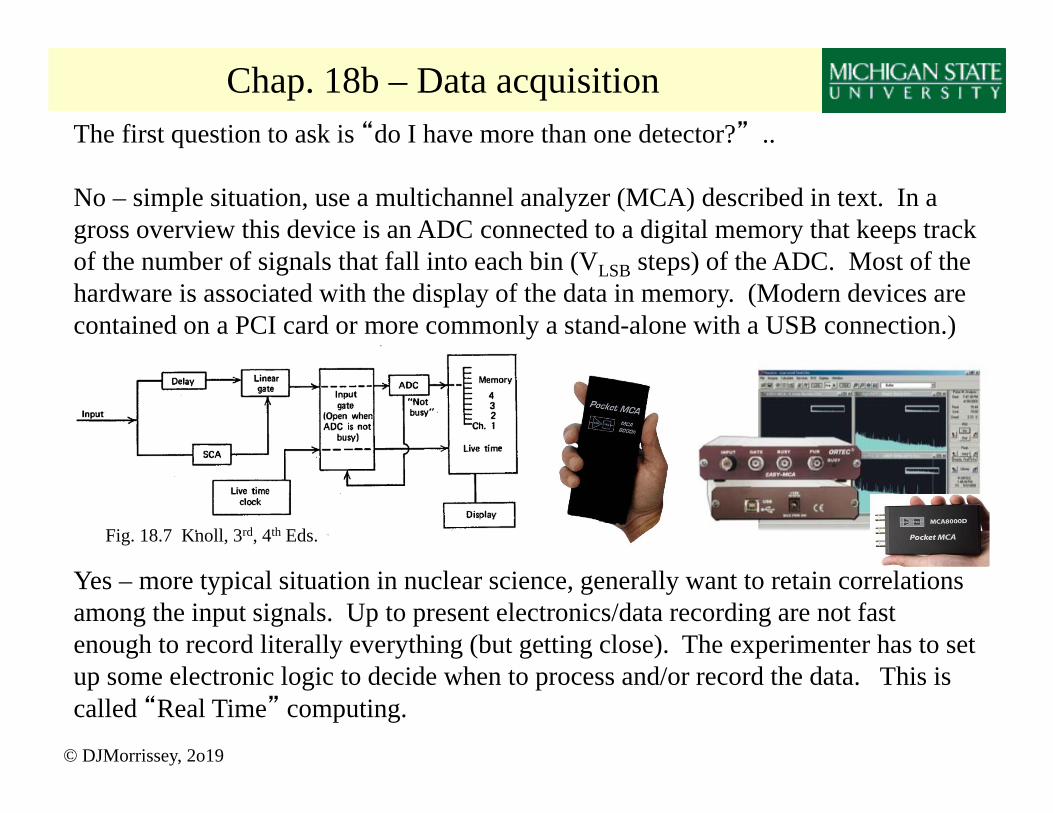
No – simple situation, use a multichannel analyzer (MCA) described in text. In a gross overview this device is an ADC connected to a digital memory that keeps track of the number of signals that fall into each bin (VLSB steps) of the ADC. Most of the hardware is associated with the display of the data in memory. (Modern devices are contained on a PCI card or more commonly a stand-alone with a USB connection.)
Yes – more typical situation in nuclear science, generally want to retain correlations among the input signals. Up to present electronics/data recording are not fast enough to record literally everything (but getting close). The experimenter has to set up some electronic logic to decide when to process and/or record the data. This is called “Real Time” computing.
© DJMorrissey, 2o19
Chap. 18b – Data acquisition
Fig. 18.7 Knoll, 3rd, 4th Eds.

© DJMorrissey, 2o19
Data Acquisition: Trigger Logic
Vi SAi ADCi CFDi Ti
Ti TDCi ID Wordi MG Logici
Master Gate
ID word (input-register)
CPU not-busy
1
2
time
The “trigger logic” is programmed to decide when to process and record the data.•The output of this logic system is usually called the “master gate.”•The logic usually also provides “guidance” to the CPU about processing the event.•The logic needs to provide a way to monitor the number of lost signals.•The logic itself can range from individual modules to a digital logic device.•Important logic units are AND, OR (Fan-in), LATCH, Gate & Delay Generator
Trivial Example: 2 equivalent detectors, record when either and/or both fire.
S Q
R Q
12
StartCPU
CPUdone
CPU is Busy
Accepted MG
Valid MG
User has to “or” all contributions to total deadtimeUser has to “or” all contributions to total deadtime

© DJMorrissey, 2o19
Data Acquisition: PID in A1900
Notes:
PPAC’s use charge-division
Bit Register (input reg., pattern reg.)TAC for precise ToF (stop/start)(time runs “backwards”)
MG is one “AND”Scalers keep count without gates
Particle ID depends on measuring:ToF v or and B m /q mZq
E mZ2 / E (Z,q integer)E-total ½ m2
“ToF”

© DJMorrissey, 2o19
6 3 3099 1111 1221 1100
Data Acquisition: data streamOptions for Multidimensional data, simple example two detectors with E & T
1) Record all values in order including zeros as placeholders (n-tuple)
3101 1106 0 03112 1120 0 0
0 0 1201 1099
2) Record only non-zero words A) embed information in data stream (plus word count, pattern register)
B) embed information in data words (plus word count)
Example of 2 detector data stream, “energy” and “time”Simple to interpret “sparse” data (recall DSSD had 80 channels, only 2 valid)error recovery from dropped words may be difficult
4 1 3101 11064 1 3112 1120
4 2 1201 1099
No gain for small experiments Data needs to be “interpreted”“dense” data
Problems from dropped words are localized
Decimal
61443 38065 42059
010010110001
1099
1001
e.g. 16 bit word 4 bit ID, 12 bit data
4B19
1201
0100010010111010
44BAHexidecimal Data needs more “interpretation”High level of error checking possible
Binary 1111
003
9 10
F
15
000000000011
3

© DJMorrissey, 2o19
Data Acquisition: Standards - NIMNIM (nuclear instrumentation module): Nuclear Physics standard container/voltages/power Only signal lines are Gate & Clear (not geographic)Generally just a power supply. (All pins on the connector block are defined but not all are used or even wired. No data “bus.”)

© DJMorrissey, 2o19
Data Acquisition: Standards
CAMAC (computer automated measurement and control): Nuclear Physics standard container/voltages/power Computer bus (back plane) with [all 86 lines connected] Address lines / write / read (24b) / control lines Bus speed 1 MHz .. Geographic: “BCNAF” “LAM”
VME (Versa Module Eurocard): industry standard container/voltages/power Computer bus Address lines (32b) / data lines (32b) / control lines Bus speed 20 MHz .. Not geographic (unless JAUX bus is used), Memory mapped … extensions VME64, VXI
NIM (nuclear instrumentation module): Nuclear Physics standard container/voltages/power Only signal lines are gate & clear (not geographic)Generally just a power supply. (All pins on the connector block are defined but not all are used or even wired. No data “bus.”)

© DJMorrissey, 2o19
Data Acquisition: Real Time ComputingFrom LA-UR-82-2718 “CAMAC Primer”
Conventional Program runs (once) in a constrained world.. even apparently interactive code such as spreadsheets have fixed input and are run once per “return character”
Real-time Program has to respond to environment and is fundamentally different. The codes spend a large fraction of time sampling input from “real world”.

© DJMorrissey, 2o19
Data Acquisition: architectures – 1 –•GPIB (general purpose interface bus):
IEEE-488 standard, 8-bit serial bus (slow)•Serial Branch Highway: loop w/ two cables•Parallel Branch Highway: thick cable, ~100 wires•Peripheral Component Interconnect 32-b 33MHz•Universal Serial Bus (2=480 Mbps, 3=5 Gbps)
All require appropriate adapter in CPU, slow because commands and data must travel up and down the line between computer and module through a crate controller.
•Auxiliary crate controller: a (small) computer in the crate with a small program to collect the data into blocks and then transfer it out on command.
Slave Master

© DJMorrissey, 2o19
Data Acquisition: architectures – 2 –•Master/Slave concept with VME-based CPU’s
the NSCL daq system in the 1990’s CAMAC modules do the work
Slave Master
Parallel BranchEthernet
VME
CAMAC VME
Parallel Branch Optical Fiber (PCI/VME bridge)Updated to USB connection
CAMAC
Back to one external CPU but connected to VME the NSCL daq system in the 2000’sVME modules are doing the work storing data in “external” memoryCAMAC runs on a slower scale handled through a VME interface
(ANL 90’s version)
Distributed systems: MIDAS
© DJMorrissey, 2o19
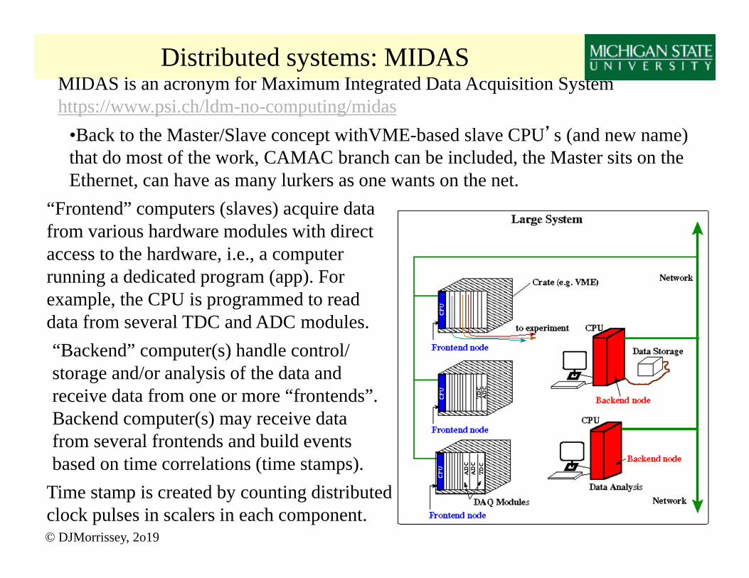
MIDAS is an acronym for Maximum Integrated Data Acquisition Systemhttps://www.psi.ch/ldm-no-computing/midas
•Back to the Master/Slave concept withVME-based slave CPU’s (and new name) that do most of the work, CAMAC branch can be included, the Master sits on the Ethernet, can have as many lurkers as one wants on the net.
“Frontend” computers (slaves) acquire data from various hardware modules with direct access to the hardware, i.e., a computer running a dedicated program (app). For example, the CPU is programmed to read data from several TDC and ADC modules.“Backend” computer(s) handle control/ storage and/or analysis of the data and receive data from one or more “frontends”. Backend computer(s) may receive data from several frontends and build events based on time correlations (time stamps).
Time stamp is created by counting distributed clock pulses in scalers in each component.

Distributed systems: g2 Expt.
© DJMorrissey, 2o19
W. Gohn, JPhysConf 664 (2015) 082014 “The data acquisition system for this experiment must have the ability to record deadtime-free records from 700 μs muon spills at a raw data rate of 18 GB per second. Data will be collected using 1296 channels of μTCA-based 800 MHz, 12 bit waveform digitizers and processed in a layered array of networked commodity processors with 24 GPUs working in parallel to perform a fast recording and processing of detector signals during the spill. The system will be controlled using the MIDAS data acquisition software package.”

© DJMorrissey, 2o19
Chap. 18 – Simple Data Acquisition Question The GETINA data acquisition system that runs at the NSCL relies on counting clock pulses in scalers to synchronize separate data streams. The clock pulses occur every 10 ns and the scalers can count up to 264 bits. What is the maximum time that this this system can run before the scaler times out?
t 264 counts / 0.10 count/ns
t 264 counts*1x10⁸ ns/count
t 256 s 7.21x10¹⁶s = 2.29x10⁹years

© DJMorrissey, 2o19
Chap. 18 – Data Acquisition Questions The NSCL SeGA data acquisition system includes successive approximation ADC's (Ortec 413A’s) that require approximately 10s to complete the (parallel) conversion of all analog signals into digital words. The ADC's reside in CAMAC crates serviced by a code running in a LINUX computer (through PCI/VME and then VME/CAMAC interfaces). The time to store a data word from the module in the computer memory is approximately 8s, assume other overhead times are negligible. (a) Estimate the dead-time per event if this system is used to readout an experiment that has ten parameters (ten data words). (b) Estimate the true rate and the fractional dead-time if this ten parameter experiment is running at the rate of 200 events/sec. (c) At what event rate will the system reach a fractional dead-time of 0.50 (at ten words/event)? [ Final Exam Question, F/2oo2 ]
a) dead-time (one event) tdigitize tstore 10sn(8s) 1010*8 90s
b) Robs R true
1 R true 200
1 200(90x106 )196 / sec
N.B. fraction dead Robs 1.8x10²
c) 0.50 Robs Robs 0.5 / 5, 555 / sec