weed brush - fresh-group.com · table of contents table of contents ... the westermann weed brush...
TRANSCRIPT

Page 0 of 54
Aggressive. User friendly. Without chemicals. W
EE
D B
RU
SH
W
KB
660
Hon
da

Page 1 of 54
Table of contents
Table of contents
Table of contents ................................................................................................................................................................................. 1
1 EC declaration of conformity..................................................................................................................................................... 3
2 Legal information ...................................................................................................................................................................... 5
3 Important general information ................................................................................................................................................... 6
3.1 Scope of delivery .............................................................................................................................................................6
3.2 Conventions .....................................................................................................................................................................7
Symbols and signal words ..................................................................................................................................7
Pictogram overview ............................................................................................................................................8
3.3 Marking on the machine ..................................................................................................................................................9
Warning pictographs on the machine .................................................................................................................9
3.4 Spare parts order ...........................................................................................................................................................10
4 Safety and security ................................................................................................................................................................. 11
4.1 Intended use of the machine .........................................................................................................................................11
4.2 Note on machine name..................................................................................................................................................11
4.3 Operator requirements...................................................................................................................................................12
4.4 Danger area ...................................................................................................................................................................13
4.5 Foreseeable misuse | Reasonably foreseeable misuse.................................................................................................14
4.6 Behaviour in case of an emergency ..............................................................................................................................14
Personal injury ..................................................................................................................................................14
Fire ...................................................................................................................................................................14
Technical complications If, during use, technical complications occur, they must be corrected by qualified personnel before further use. ..................................................................................................................................................................14
4.7 Range of application ......................................................................................................................................................15
Local requirements ...........................................................................................................................................15
Disposal ............................................................................................................................................................15
4.8 Responsibility of the operator ........................................................................................................................................16
Obligations of the operator ...............................................................................................................................16
4.9 Personnel responsibility .................................................................................................................................................17
4.10 Observance of the operating instructions ......................................................................................................................18
4.11 Residual dangers and safety measures.........................................................................................................................18
4.12 Safety markings on the machine ...................................................................................................................................18
4.13 Personal protective equipment ......................................................................................................................................19
5 Safety notes for the operator/user .......................................................................................................................................... 20
6 Technical data ........................................................................................................................................................................ 21
6.1 General technical data WKB 660 Honda .......................................................................................................................21
6.2 General technical data WKB 660 ...................................................................................................................................22
7 Assembly, initial commissioning ............................................................................................................................................. 23
7.1 Safety and security ........................................................................................................................................................23
7.2 Assembly .......................................................................................................................................................................23
7.3 Initial commissioning......................................................................................................................................................23
8 Product description ................................................................................................................................................................. 24
9 Commissioning ....................................................................................................................................................................... 25
9.1 Adjusting the handle height ...........................................................................................................................................25

Page 2 of 54
Table of contents
Adjustment procedure ......................................................................................................................................25
9.2 Adjusting the axle height................................................................................................................................................25
9.3 Adjusting the all-round protection ..................................................................................................................................26
9.4 Engine start WKB 660 Honda ........................................................................................................................................27
Opening the fuel valve ......................................................................................................................................27
Cold start ..........................................................................................................................................................28
Start at operating temperature ..........................................................................................................................28
Pull cable ..........................................................................................................................................................28
After the cold start ............................................................................................................................................28
9.5 Starting the cleaning process WKB 660 Honda .............................................................................................................29
9.6 Engine stop WKB 660 Honda ........................................................................................................................................30
10 Operation ................................................................................................................................................................................ 31
10.1 Procedure description ....................................................................................................................................................31
10.2 Service interval ..............................................................................................................................................................31
11 Maintenance and servicing ..................................................................................................................................................... 32
11.1 General information .......................................................................................................................................................32
11.2 Engine WKB 660 Honda ................................................................................................................................................33
11.3 Lubrication .....................................................................................................................................................................33
11.4 Replacing the brush element .........................................................................................................................................34
Removal and attachment of wire brush braids..................................................................................................34
11.5 Replacing the V-belt | Tightening the V-belt ..................................................................................................................35
Belt overview WKB 660 Honda.........................................................................................................................36
Engine belt replacement ...................................................................................................................................36
11.6 Screw fittings .................................................................................................................................................................37
11.7 Measures after maintenance .........................................................................................................................................38
11.8 Note on servicing work ..................................................................................................................................................38
11.9 List of records ................................................................................................................................................................38
12 Residual dangers .................................................................................................................................................................... 39
13 Storage conditions .................................................................................................................................................................. 41
14 Cleaning ................................................................................................................................................................................. 42
15 Troubleshooting ...................................................................................................................................................................... 43
15.1 WKB 660 Honda ............................................................................................................................................................43
16 Decommissioning ................................................................................................................................................................... 44
16.1 Decommissioning ..........................................................................................................................................................44
16.2 Disassembly/Disposal....................................................................................................................................................44
17 Warranty policy ....................................................................................................................................................................... 45
18 Spare parts list ........................................................................................................................................................................ 48
18.1 WKB 660 Honda ............................................................................................................................................................48
Main components .............................................................................................................................................48
Base frame .......................................................................................................................................................49
Belt overview ....................................................................................................................................................50
Brush container WKB .......................................................................................................................................51
Handle ..............................................................................................................................................................52
19 List of figures .......................................................................................................................................................................... 53

Page 3 of 54
EC declaration of conformity
1 EC declaration of conformity
EC declaration of conformity according to
Machinery Directive 2006/42/EC Annex II 1.A
The producer / distributor:
Westermann GmbH & Co. KG
Schützenhof 23 D – 49716 Meppen
hereby declares that the following product
Product name: WKB 660 Honda
Make: Westermann GmbH & Co. KG
Serial number: 66. _ _ _ _
Series/type designation: WKB 660
Description:
The Westermann weed brush is designed exclusively for normal usage in the cleaning of paved areas such as yards, streets, parking lots, silo slabs and stables that are heavily infested by debris. Any use beyond this is considered improper use. The manufacturer is not liable for any resulting damage! This risk is carried solely by the user.
The Intended use also includes compliance with the operating, maintenance and repair conditions specified by the manufacturer.
The following additional EU directives have been applied:
The protection objectives of the following EC directive are adhered to. Machinery Directive 2006/42/EC
EMC Directive 2014/30/EU

Page 4 of 54
EC declaration of conformity
The following harmonised standards have been applied:
EN ISO 12100:2010 Safety of machinery - General principles for design - Risk assessment and risk reduction (ISO 12100:2010)
The following other technical specifications have been applied:
Name and address of the person authorised to compile the technical documentation:
Westermann GmbH & CO. KG
Mr. Alfons Westermann Tel.: 05931 | 496 90 0
Schützenhof 23 Email: [email protected]
49716 Meppen URL: www.westermann-radialbesen.de
Place: 49716 Meppen
Date: 13/07/2018
_______________________________
(signature)
Alfons Westermann Managing Director

Page 5 of 54
Legal information
2 Legal information
Publisher: Westermann GmbH & CO. KG
Address: Schützenhof 23 ▪ 49716 Meppen
Phone: +49 (0) 5931 | 496 90 0 ▪ Fax: +49 (0) 5931 | 496 90 99
Email: [email protected]
Internet: http://www.westermann-radialbesen.de
Managing Director: Alfons Westermann
Form of organisation: Limited partnership
Location: 49716 Meppen
Commercial Register Osnabrück, HRA 100274
Personally liable partner:
Westermann Beteiligungs-GmbH,
HRB Osnabrück no. 100562,
UST-ID no.: 193643718,
Copyright notice:
The contents of this document are protected by copyright under German copyright law and international treaties.
All copyrights to the contents of this document are owned by UPAS GmbH unless and to the extent that another author is expressly indicated or obviously recognisable.
The user is not granted or reserved any industrial property rights, rights of use or other rights by the provision of the contents. The user is prohibited from registering rights of any kind for the know-how or parts thereof.
The passing on, transfer and other dissemination of the contents of this document to third parties,
the making of copies, duplicates and other reproductions as well as the utilization and other use – even in part – are prohibited without the prior, express and written consent of the author, unless and insofar as mandatory statutory provisions permit such use.
Infringements against copyright are illegal, according to §§ 106 ff. Copyright Act and grant the holders of copyrights claims for injunctive relief and damages.
Subject to change:
The Westermann GmbH & Co. KG reserves the right to change this document and the subject matter described therein
at any time without prior notice, in particular to improve and expand it, provided and insofar as contractual agreements or
legal requirements do not conflict with this.

Page 6 of 54
Important general information
3 Important general information
3.1 Scope of delivery
The operating instructions are an integral part of the working equipment and must be kept in the immediate vicinity of the machine and be accessible at all times.
The operating instructions contain important information for the safe and effective operation. The operator must therefore have carefully read and understood these operating instructions.
The prerequisite for safe working is adherence to all safety notes and instructions given in these operating instructions.
The local accident prevention regulations and general safety regulations for the specific area of application must also be observed.
The supplier documentation provided with the installed components must also be observed.
The figures are for general understanding only and may differ from the actual model.
The manufacturer accepts no liability for damage resulting from non-observance of the operating instructions, improper use, improper maintenance or repairs, unauthorised modifications, technical modifications and use of unauthorised spare parts.

Page 7 of 54
Important general information
3.2 Conventions
Symbols and signal words
Symbol / signal word
Meaning
Indicates the handling and effects of the safety information.
Alerts you to a dangerous situation that, if not avoided, will result in death or serious injury.
Alerts you to a dangerous situation that, if not avoided, may result in death or serious injury.
Alerts you to a dangerous situation that, if not avoided, may result in minor or moderate injury.
Indicates possible damage to property and other important information.

Page 8 of 54
Important general information
Pictogram overview The safety notes within these operating instructions, which may endanger persons and the machine if not observed, are specifically marked by the following pictograms.
Pictogram Meaning
General warning sign
Warning of danger of falling
Warning of automatic startup
Warning of counter-rotating rollers (danger of being drawn in)
Warning of harmful or irritating substances
Warning of toxic substances
Warning of hand injury
Warning of hot surface
Warning of danger of crushing
Warning of danger of slipping
Warning of electrical voltage
Warning of obstacles on the ground

Page 9 of 54
Important general information
3.3 Marking on the machine
A rating plate containing all basic data is attached to the weed brush WKB 660. Components and accessories by suppliers carry their own rating plates.
Westermann GmbH & Co. KG
Made in Germany
Schützenhof 23
D - 49716 Meppen
Type: WKB 660 Honda
Year: ___________________
SN: ___________________
Warning pictographs on the machine
Article number: AUF-00-00016
Article number: AUF-00-000028
All labels must always be kept clean.
Missing or damaged labels must be replaced.
66 20

Page 10 of 54
Important general information
3.4 Spare parts order
When ordering spare parts or accessories, the type designation, machine number and year of manufacture must be stated. The use of accessories and spare parts from other manufacturers is only permitted after consultation with the manufacturer. The use of original accessories and accessories authorised by the manufacturer serves safety purposes. The use of other accessories may invalidate liability for any damage resulting therefrom.

Page 11 of 54
Safety and security
4 Safety and security
4.1 Intended use of the machine
The Westermann weed brush WKB 660 is to be used exclusively for the intended purpose described here. The WKB 660 is a hand-operated work machine. The work machine is used to remove weeds and debris from paved areas such as yards, paths, parking lots, silo slabs and stables.
The weed brush basically includes only the wire brush braids. The approved attachments are listed in the chapter Accessories.
Any use beyond this is considered improper use. The manufacturer is not liable for any resulting damage! This risk is carried solely by the user. The Intended use also includes compliance with the operating, maintenance and repair conditions specified by the manufacturer.
4.2 Note on machine name Hereinafter, the weed brush WKB 660 Honda will simply be referred to as
machine, WKB or weed brush.

Page 12 of 54
Safety and security
4.3 Operator requirements
Danger due to misuse! Misuse can lead to dangerous situations.
Therefore: Any use beyond or different from the intended use must be avoided.
Strictly adhere to all information in this operating manual and, if applicable,
associated documents.
Switching operations on the control elements should only be carried out by
instructed persons.
Maintenance and servicing should only be carried out by trained maintenance personnel.
Refrain from modifying, retrofitting or altering the design or individual pieces of
equipment with the aim of changing the area of application or usability.
Use the operating resources only with the aids specified in the operating
instructions.
Only use the operating resources when they are in a technically perfect condition.
Use in areas with explosive atmospheres is prohibited.
Do not exceed the load capacity of the equipment.
Refrain from transporting persons with the equipment.
Maintenance and repair Maintenance and repair work are part of the intended use and must be carried out according to the maintenance intervals.

Page 13 of 54
Safety and security
4.4 Danger area
Danger when staying in the danger area! Staying in the danger area is associated with risks that cannot be assessed by unauthorised persons. Therefore: Always observe the danger area during operation and
ensure that no persons are present therein.
If an unauthorized person moves into the danger area,
warn the person and stop the operation immediately.
The area surrounding the machine plus a safety distance of at least five metres is declared the danger area. During the working process, the area must be free of persons in order not to influence the working process and to prevent dangerous situations. Depending on their size, attachments and sweepings that are flung away can increase the danger area of the machine.
Fig 1 - Danger area
5 m
5 m

Page 14 of 54
Safety and security
4.5 Foreseeable misuse | Reasonably foreseeable misuse
All use deviating from the intended use are regarded as misuse and are not permitted. This includes, e.g.
• transport of people and animals
• use as a climbing aid
• use outside the permissible operating limits
4.6 Behaviour in case of an emergency
Personal injury If, during use, an incident occurs that results in personal injury, the reaction must correspond to the severity of the injury.
Fire If a fire occurs, immediate actions must be taken.
• Protect people
• Fight the fire
• Repair the damage
Technical complications If, during use, technical complications occur, they must be corrected by qualified personnel before further use.
Keep calm Save people
Inform first aiders

Page 15 of 54
Safety and security
4.7 Range of application
The range of application includes all sites worldwide that allow for the safe use of the machine. The application must be in accordance with the specified intended use.
Local requirements The range of application includes all sites worldwide that allow for the safe use of the machine. The following criteria must be met.
Safe assembly of the machine
Temperature range between max. -10°C and +40°C
Suitable area of use for safe use of the WKB 660.
Disposal The hazardous substances must be disposed of separately to ensure an environmentally acceptable disposal. All other materials must be sorted by their material quality and disposed of accordingly.

Page 16 of 54
Safety and security
4.8 Responsibility of the operator
If the machine is to be used commercially, the operator is subject to the statutory provisions on work safety.
Obligations of the operator
The operator is responsible for the perfect condition of the machine.
The operator must regularly check all safety devices for their functionality and completeness.
The operator must ensure that the scheduled maintenance work is carried out as scheduled.
The operator must inform the manufacturer immediately of any damage found.
The operator must provide the personnel with the necessary protective equipment and check, maintain and replace defective parts according to the regulations.
The operator must request a new copy of the operating instructions if they are in poor condition or if parts are missing.
The operator must immediately replace all markings, signs or labels that are in poorly legible condition or that have been lost
The operator must keep the working areas and escape routes free and in perfect condition.

Page 17 of 54
Safety and security
4.9 Personnel responsibility Preconditions
Only persons who are expected to observe the safety regulations and perform their work reliably may enter the danger area.
Persons whose ability to act is influenced by drugs, alcohol, medicines, etc. are not permitted.
When selecting personnel, the age and occupation-specific regulations applicable at the location of use must be observed.
The user must be at least 16 years old!
Qualifications As a rule, all personnel may only carry out actions for which they have the necessary qualifications.
Qualified personnel for installation and commissioning
Due to their professional training, knowledge and experience as well as knowledge of the relevant regulations, they are able to perform the work assigned to them and to recognize and avoid dangerous situations independently.
Service personnel for maintenance and commissioning
Due to their professional training, knowledge and experience as well as knowledge of the relevant regulations, they are able to perform the work assigned to them and to recognize and avoid possible dangers independently.
Electrically qualified person for maintenance, installation and commissioning
Due to their professional training, knowledge and experience as well as knowledge of the relevant standards and regulations, they are able to perform work on the electrical components and to recognize and avoid possible dangers independently. The electrically qualified person is trained for the specific site at which he works and knows the relevant standards and regulations.
Instructed operating personnel for operation
Has been instructed by the operating company on the tasks assigned to him and possible dangers in the event of improper behaviour.

Page 18 of 54
Safety and security
4.10 Observance of the operating instructions
The operating instructions are supplied by the manufacturer or supplier of the product in order to impart essential knowledge to the user for the proper and safe use, and to point out dangers in handling the machine.
Before commissioning the machine, the operating instructions must be read through; they must be strictly observed during commissioning. We would like to point out that we accept no liability for damage or malfunctions resulting from non-observance of the operating instructions.
We reserve the right to make technical changes, which are necessary for the improvement of the machine, to the illustrations and information in these operating instructions.
4.11 Residual dangers and safety measures The knowledge and technical implementation of the safety notes within this documentation is a prerequisite for a faultless product. However, this documentation cannot cover every detail of every conceivable case of machine application. Therefore, as in any other case, a residual risk in particular due to human error remains. This documentation is intended to minimise this residual risk.
4.12 Safety markings on the machine Danger and warning points as well as important information must be clearly marked on the machine and must be cleaned or replaced if they become dirty or unrecognisable.

Page 19 of 54
Safety and security
4.13 Personal protective equipment
Personal protective equipment (PPE) is not included in the scope of delivery. Responsibility for the presence, inspection and correct use of PPE therefore lies with the operator.
Wear PPE according to the following instructions.
Do not enter the danger area without PPE.
Follow the instructions on the PPE attached to the equipment.
Use foot protection
Protection of the feet against heavy falling objects, slipping, stepping on sharp objects lying around.
Use protective clothing
Tight working clothes with low tensile strength, narrow sleeves and no protruding parts. Mainly protection against being drawn into rotating machine parts. When working on electrics, use working clothes with arc protection.
Use hand protection
Protection of the hands against friction, abrasions, stabs and cuts and contact to hot surfaces. When working on live parts, use insulated protective gloves.
Use hearing protection
Protection of the auditory system against harmful sound frequencies.

Page 20 of 54
Safety notes for the operator/user
5 Safety notes for the operator/user
If other persons are to operate the machine, they must be instructed on the operation of the machine and read through and understand the operating instructions in order to avoid accidents.
Before removing safety devices such as a safety cover, make sure that all moving parts of the machine have stopped. Removed components must be reinstalled after maintenance.
Before commencing work with the machine, ensure that no persons, animals, obstacles, etc. are in the area of the machine to prevent personal injury or damage to property.
Never transport persons on the machine or attachments.
The surface to be swept must first be cleaned of larger foreign bodies. Stones, wires, pieces of wood and the like may also be uncontrollably flung away by the weed brush. Observe chapter 4.4 Danger area on page 13!
Notes WKB 660 Honda Please never leave the device run unattended!
Familiarise yourself with the handling of the engine. Remember how to turn off the engine in an emergency.
Do not place any objects on the engine or put flammable liquids into its vicinity.
Do not tilt the machine over 20°, or fuel may leak.
Keep your feet and hands away from rotating wire bristles.
The combustion engine will reach high temperatures. Ensure that neither persons nor objects approach the hot engine.
During operation the exhaust becomes extremely hot and only cools down some time after the engine has been switched off. Do not touch the exhaust while it is hot. To avoid severe burns and the danger of fire, allow the engine to cool down before transportation or storing in a locked room !

Page 21 of 54
Technical data
Fig. 2 - Technical data
6 Technical data
6.1 General technical data WKB 660 Honda
Main dimensions WKB 660 Honda Unit
Machine length: 1.80 metre [m]
Machine width: 0.75 metre [m]
Working width: 0.66 metre [m]
Machine height: 0.71 metre [m]
Total height, variable: 0.85 - 1.45 metre [m]
Sound power level LWA: 81 dB
Machine length
Machine width
Tota
l hei
ght
Mac
hine
hei
ght

Page 22 of 54
Technical data
Fig. 3 - Technical data
6.2 General technical data WKB 660
Technical data WKB 660 Honda
Engine: Honda GXV 160 CO2 value: 874 g/kW-h
The results of the CO2 measurements follow from tests with a (parent) engine at defined test cycles under laboratory conditions. The engine is representative of the engine family and can neither include nor guarantee the performance of a single engine. The CO2 values of the Honda engines with EU type approval and the required declaration in English are published at: http://www.honda-engines-eu.com/co2-engines
Period of use: continuously
Steering bar: height-adjustable
Working width: approx. 660 mm
Direction of rotation: right
Weight: 95 kg
Tyres: 260 / 85 foam-filled
Guiding wheel: none
Brush: 3 rotating wire brushes ά 4 wire brush braids
Area capacity: 1,800 m²/h (depending on the degree of contamination)
Page 23 of 54
Assembly, initial commissioning
7 Assembly, initial commissioning
7.1 Safety and security
In order to guarantee the safety of human and machine, the simple and risk-minimising assembly/handling was considered as early as during the design. The handling device is therefore subject to all applicable DIN EN standards. Operator training and instructions are required and further reduce the safety risk.
7.2 Assembly The complete assembly and initial commissioning is carried out exclusively by the manufacturer. The machines are subjected to an extensive test run and only delivered after the successful approval.
7.3 Initial commissioning Before initial commissioning, check the entire vehicle for damage.

Page 24 of 54
Product description
8 Product description
The Westermann WKB 660 is designed and constructed for the demanding user. It is possible to remove weeds and debris from paved areas such as yards, paths, parking lots, silo slabs and stables.
The powerful 4-stroke petrol engine ensures effortless work and high operational availability.
Via the Bowden cable on the base frame the machine is easily operable. The machine design of the WKB 660 allows for the usage in almost every nook and cranny. The angle of the brush levels any unevenness. The three brush heads guided by planetary gears ensure an optimal cleaning result in the entire brush area.
Fig. 4 - Sweeping principle WKB
The general safety notes listed in main chapter "Safety and security" as well as the special safety notes in the other main chapters must be observed.
The base frame consists of a robust, galvanised, torsion-free steel construction that qualifies the WKB for use in the agricultural field.

Page 25 of 54
Commissioning
9 Commissioning
To commission the hand-operated power sweeper, it is moved from its standby position to the working position.
9.1 Adjusting the handle height A handle height adjustment serves to set the height of the handle without the help of any tools. This allows the handle height to be ergonomically adjusted for different body sizes in short time.
Adjustment procedure
Fig. 5 - Handle height
Unlock the locking bolt on both sides as shown in the illustration.
Swivel the handle to the desired working position.
Properly relock the locking bolt in the bore pattern.
9.2 Adjusting the axle height Depending on the degree of wear of the braided wires, the adjustable axle of the machine must be readjusted. The horizontal alignment ensures the clean and even wear of the wire brush braids.
Fig. 6 - Axle adjustment
Unlock the locking bolt on both sides as shown in the illustration.
Raise or lower the machine to the desired position.
Observe the horizontal alignment of the machine.
Properly relock the locking bolt in the bore pattern.

Page 26 of 54
Commissioning
9.3 Adjusting the all-round protection
The height of the all-round protection must be adjusted via the adjusting screws to ensure a ground clearance of approx. 2 cm between the lower edge of the all-round protection and the ground at all times.
Fig. 7 - All-round protection adjusting screws
Fig. 8 - Ground clearance 2 cm
Adju
stin
g sc
rew
s Adju
stin
g sc
rew
s
Gro
und
clea
ranc
e (a
ppro
x. 2
cm
)

Page 27 of 54
Commissioning
9.4 Engine start WKB 660 Honda
Before starting the engine, make sure that the belt tension lever is in the neutral position (as shown in the figure).
Fig. 9 - Engine start null position
Fig. 10 - Fuel valve
Opening the fuel valve The fuel valve is located on the left in the
direction of travel, below the air filter.
Swivel to the right » Open
OFF ON
FUEL VALVE

Page 28 of 54
Commissioning
Fig. 11 - Control cold start
Cold start Move the hand throttle to the rearmost position
(choke).
START
Fig. 12 - Control operating temperature
Start at operating temperature Move the hand throttle into position slightly
above idle.
between MIN and MAX
Fig. 13 - Pull cable
Pull cable First slightly tug the knob of the pull cable until
resistance is felt, then pull firmly.
Please allow the pull cable knob to run back slowly. This way
you avoid damage to the engine.
Fig. 14 - Start operating temperature
After the cold start
If the engine was started using the choke, wait until it has warmed up and is running smoothly without choke, then set the hand throttle to the fastest or maximum position. Now set the hand throttle to the desired engine speed. Optimal performance at full throttle.

Page 29 of 54
Commissioning
9.5 Starting the cleaning process WKB 660 Honda
The weed brush is provided with a robust start and stop mechanism for the brush head. Brush rotation is activated via the shown handle, which can be easily accessed from the normal working position.
Fig. 15 - Determining the sweeping direction
Pull the hand lever up.
As the type of power transmission from the engine to the brush element is a V-belt drive, a certain amount of friction is required. The degree of wear and operating time of the belts must be observed regularly.

Page 30 of 54
Commissioning
9.6 Engine stop WKB 660 Honda
Move the hand lever to the neutral position (front end position) to stop the rotation of the brush element. Now move the hand throttle to the "Min" position and then to the stop position.
Fig. 16 - Engine STOP
Now close the fuel valve if you do not want to put the machine back into operation immediately.
Fig. 17 - Close fuel valve
FUEL VALVE
ON
OFF

Page 31 of 54
Operation
10 Operation
10.1 Procedure description
Start in standby position, then move from standby position to working position
Depending on the amount of cleaning and the degree of contamination, a reaction force is generated on the hand-operated machine which must be compensated by the operator. An abrupt reaction force (kickback) may also occur when the rotating weed brush is pushed against a solid resistance. Please be careful here!
10.2 Service interval The first 50 operating hours greatly influence the performance and service life of the machine. The following aspects should be considered to make sure that you can enjoy your WKB 660 for a long time. Check nuts, bolts and screws etc. repeatedly and retighten them if
necessary.
Proper maintenance is crucial for the operational safety of the machine.

Page 32 of 54
Maintenance and servicing
11 Maintenance and servicing
11.1 General information
All maintenance, repair and modifying work on the WKB 660 must only be carried out when it is stopped, the power supply disconnected or the engine switched off. The procedure for stopping the machine must be strictly adhered to as described in the operating instructions.
The WKB 660 must be secured in a stable position and prevented from
rolling away.
The safety regulations in Chapter 4 apply.
Modifying or altering the machine is only permitted in agreement with the manufacturer. The use of original spare parts and accessories authorised by the manufacturer serves safety purposes. Using any other parts excludes liability for the resulting consequences.
Observe before commencing work:
• Visually check for damage and defects! Report any changes (including changes in operating behaviour) immediately to the responsible service personnel! If necessary, arrange for immediate decommissioning!
• Check for completeness and functionality of all accessories. Worn or functionally restricted parts must be replaced. Replacement parts must be ordered from the manufacturer.
• Check for completeness and legibility of all rating plates, information signs and operating instructions. Replace missing or illegible signs and documents.

Page 33 of 54
Maintenance and servicing
Observe during regular maintenance work:
• If necessary, digitally filed maintenance instructions must be available in paper form during maintenance.
• For maintenance work involving components from other manufacturers, consult the documentation of the third-party manufacturer if necessary.
• Maintenance work requiring expert knowledge should be carried out by service personnel.
• No less than the intervals specified in the maintenance schedule must be observed; however, they may be shorter depending on the operator's specifications and ambient conditions.
• Correct safety-relevant defects immediately! • Only use original spare parts and accessories/tools approved by the
manufacturer.
• Only use components with the required specification.
11.2 Engine WKB 660 Honda
Instructions for the maintenance and care of the engine can be found in the enclosed operating instructions. It contains all
necessary engine-relevant maintenance steps such as oil change, spark plug change and inspection intervals.
11.3 Lubrication Regularly check the wheel and brush bearings for leaks. Damaged bearing units must be replaced!

Page 34 of 54
Maintenance and servicing
Fig. 18 - Changing the wire brush braids
11.4 Replacing the brush element
If the braided wires show signs of wear or defects, it is possible to replace each wire brush braid with a new one individually. Please follow the steps below.
Removal and attachment of wire brush braids Empty the fuel tank of the WKB 660 Honda to be able to tilt the power sweeper. Now tilt the power sweeper backwards to enable access (lay handles on the floor to stabilise the machine and ensure safe access).
Risk of crushing due to falling weed brush! The weed brush can uncontrollably be tilted by external influences, thus causing dangers.
Therefore: Tilt the weed brush by carefully following the steps. If necessary, secure the weed brush in its position by placing
additional weight on the handle.
Fig. 19 - Replacing the brush element
The wire brush braids are located in one of the three mounting consoles. Each mounting console has four mounting points for the separate wire brush braids. The braided wire can easily be pulled out from below by unlocking the mini indexing plungers as shown in the figure. If the other braided wires show similar signs of wear, this step must be repeated.
Reassemble by following the disassembly steps in reverse order.

Page 35 of 54
Maintenance and servicing
11.5 Replacing the V-belt | Tightening the V-belt Loosen the two clamping screws of the brush container V-belt as shown in the figure, then push the plate opposite to the direction of travel. Push the plate in so far that the V-belt, which runs along the groove in the brush container, relaxes as much as possible.
Fig. 20 - Belt clamping screws
Now lever the V-belt out of the groove, moving it from bottom to top (use a screwdriver if necessary). Turn the brush element until the V-belt moves up and out of the groove completely.
Drive belt designation: SPZ 2137 Please use original fabric V-belts from the authorized dealer only!
Reassemble by following the steps in reverse order. The V-belt clamping screw must now be readjusted to ensure proper power transmission from the engine to the brush element. Tension the V-belt with an appropriate tool (e.g. screwdriver) by inserting it into the grooves shown above and applying the levering force required for tensioning the V-belt.
Please make sure that you do not overtighten the plate and the clamping screws, or the bearing of the engine or brush will be damaged. Put two fingers against the V-belt and try to push it in for approx. 20mm. If this is possible, the tension is sufficient to transmit the power.

Page 36 of 54
Maintenance and servicing
Belt overview WKB 660 Honda
Fig. 21 - Replacing the direction-changing belt
Engine belt replacement Before the engine belt can be replaced, the SPZ drive belt must be properly removed.
Loosen the belt guide plate to access and lever out the belt in the groove of the SPA belt pulley. Follow the steps in reverse order to put the new V-belt into the groove of the engine drive pulley and drive pulley.
Drive belt designation: V-belt 13 x 900
Please use original belts from the authorized dealer only!
Finally, install the belt guide plate and the drive belt according to the technical requirements in these operating instructions.
Drive belt SPZ
Engine pulley
Tension pulley
SPA Belt
SPZ belt pulley
SPA belt pulley
Belt guide plate

Page 37 of 54
Maintenance and servicing
11.6 Screw fittings
Check bolts and nuts for tightness after five hours of operation for the first time, then regularly (every 50 hours) and retighten if necessary.
• All torques TA are standard values for standard metric threads according to DIN. Coefficient of friction 0.14 - new screws - unlubricated. These values have been recommended as standard values by various screw manufacturers. We cannot assume any liability for the application.
• Self-locking nuts must be replaced after each disassembly.
Thread 3.6 5.6 6.8 8.8 10.9 12.9
M6 3.43 4.51 8.73 10.3 14.71 17.65
M8 8.24 10.79 21.57 25.50 35.30 42.17
M10 16.67 21.57 42.17 50.01 70.61 85.32
M12 28.44 38.25 73.55 87.28 122.58 147.10
M14 45.11 60.80 116.70 135.27 194.17 235.36
M16 69.63 93.16 178.46 210.84 299.10 357.94
M18 95.13 127.40 245.17 289.30 411.88 490.34
M20 135.33 180.44 348.14 411.88 576.50 669.26
M22 162.40 245.17 470.72 558.98 784.45 941.44

Page 38 of 54
Maintenance and servicing
11.7 Measures after maintenance
After completing all maintenance work, perform the following steps:
• Make sure that all previously loosened bolts are tightened.
• Make sure that all previously removed safety devices and covers are properly reinstalled.
• Make sure that all tools, materials and other equipment that have been used are removed from the working area.
• Clean the working area and remove cleaning material such as cleaning rags etc.
• Make sure that all safety devices function properly.
11.8 Note on servicing work Only original spare parts may be used for servicing work and components replaced for this reason.
11.9 List of records
Events and interventions must be recorded in a list of records. The lists of records must be filed digitally and/or in paper form.
Page 39 of 54
Residual dangers
12 Residual dangers
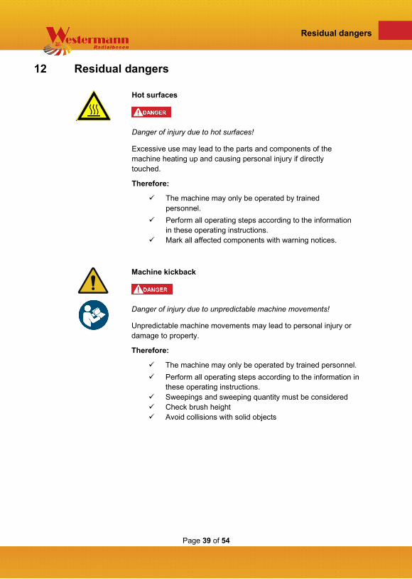
Hot surfaces
Danger of injury due to hot surfaces!
Excessive use may lead to the parts and components of the machine heating up and causing personal injury if directly touched.
Therefore:
The machine may only be operated by trained personnel.
Perform all operating steps according to the information in these operating instructions.
Mark all affected components with warning notices.
Machine kickback
Danger of injury due to unpredictable machine movements!
Unpredictable machine movements may lead to personal injury or damage to property.
Therefore:
The machine may only be operated by trained personnel. Perform all operating steps according to the information in
these operating instructions. Sweepings and sweeping quantity must be considered Check brush height Avoid collisions with solid objects

Page 40 of 54
Residual dangers
Improper operation
Danger of injury due to improper operation!
Improper operation may lead to personal injury or damage to property.
Therefore:
The machine may only be operated by trained personnel. Perform all operating steps according to the information in
these operating instructions. Before commencing work, ensure that all fastenings are
properly installed and undamaged. Observe order and cleanliness! Loose objects such as tools,
cables and components that are lying around or piled up are sources of accidents.
Movements during operation
Danger of injury due to moving components!
During operation, individual components or parts of the machine may move and lead to dangerous situations.
Therefore:
Always observe the danger area during operation and ensure that no unauthorised persons are present therein.
Use the main switch to switch off the equipment and secure it against reactivation before performing any work on the machine.
Perform all operating steps according to the information in the operating instructions.
Do not operate the machine without the safety devices. Before commencing work, firmly mount all safety devices.

Page 41 of 54
Storage conditions
13 Storage conditions
Park the Westermann WKB 660 in a dry and clean place and secure it against accidental reactivation.
Danger of accidents!
Secure the weed brush in a stable position and prevent it from rolling away.
• Park the machine horizontally in standby position.
Check the vehicle for damage! Clean the WKB thoroughly if necessary. Dirt attracts moisture and leads to corrosion. Repair paint damage if necessary.
Fig. 22 - WKB 660
Fig. 23 - Standby position

Page 42 of 54
Cleaning
14 Cleaning
The following points must be observed for cleaning.
• Cleaning with water or a high-pressure cleaner is not permitted.
• Clean only with compressed air or aids such as hand brushes.
Dirt attracts moisture and leads to corrosion.
Page 43 of 54
Troubleshooting
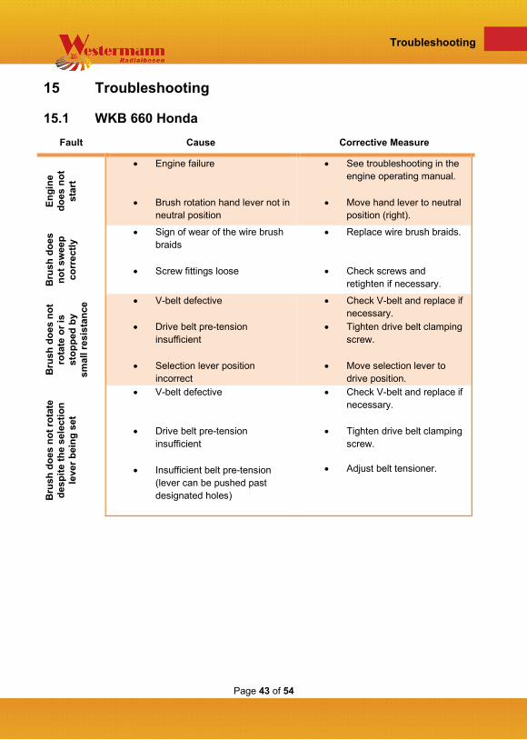
15 Troubleshooting
15.1 WKB 660 Honda Fault Cause Corrective Measure
Engi
ne
does
not
st
art
• Engine failure
• Brush rotation hand lever not in neutral position
• See troubleshooting in the engine operating manual.
• Move hand lever to neutral position (right).
Bru
sh d
oes
not s
wee
p co
rrec
tly • Sign of wear of the wire brush
braids
• Screw fittings loose
• Replace wire brush braids.
• Check screws and retighten if necessary.
Bru
sh d
oes
not
rota
te o
r is
stop
ped
by
smal
l res
ista
nce • V-belt defective
• Drive belt pre-tension
insufficient
• Selection lever position incorrect
• Check V-belt and replace if necessary.
• Tighten drive belt clamping screw.
• Move selection lever to drive position.
Bru
sh d
oes
not r
otat
e de
spite
the
sele
ctio
n le
ver b
eing
set
• V-belt defective
• Drive belt pre-tension insufficient
• Insufficient belt pre-tension (lever can be pushed past designated holes)
• Check V-belt and replace if necessary.
• Tighten drive belt clamping screw.
• Adjust belt tensioner.

Page 44 of 54
Decommissioning
16 Decommissioning
16.1 Decommissioning
After decommissioning, the WKB must be stored properly:
Observe the following when storing the machine:
• The WKB must be positioned and safely secured to prevent it from tipping over or falling.
• The ambient conditions at the storage location must match the required conditions (see technical data).
• Machinery without adequate protection must be protected from climatic influences and aggressive substances if these can affect safety.
If the machine is not used for a longer period of time, conservation measures may have to be taken to prevent corrosion and other damage.
16.2 Disassembly/Disposal Disassembly/disposal should be performed by a specialist. Recycling and waste management specialists make sure that waste is correctly disposed of and recycled. The available raw materials of the weed brush must be sorted according to disposal type and material. The copper-containing components such as cables can be recycled. Equipment such as fuses, batteries, capacitors, controls, etc. must be disposed of as electrical scrap; they may not be disposed of with the household waste to prevent damage to the environment. The carrier frame and the protective hoods can be recycled as scrap metal.

Page 45 of 54
Warranty policy
17 Warranty policy
The following policies are valid from 01.01.2002 for the Westermann warranty.
1. For Westermann products of the consumer goods sector (private use), which
have been sold via the Westermann specialist trade, the warranty period is 2 years from the date of sale to the end customer. For Westermann products of the capital goods sector (commercial/professional), which have been sold via the Westermann specialist trade, the warranty period is 1 year from the date of sale to the end customer.
2. The warranty covers defects which can be traced back to material and/or manufacturer defects. All faults occurring due to a Westermann product or production defect during the warranty period will be acknowledged and corrected by repair or a spare parts delivery via a Westermann specialised dealer.
3. Excluded from this are wear parts such as Bowden cables, starter ropes, V-belts, bearings, clutch plates, tyres, air filters, spark plugs, glow plugs, fuel filters, oil filters, sweeping brushes, rubber lips, batteries if these cannot be proven to have clear material defects.
4. Warranty claims are generally excluded in the event of inadequate maintenance and care. Regular maintenance and cleaning of the product as specified in the Westermann operating instructions is essential. Damage due to improper maintenance and cleaning cannot be accepted as a case of warranty.
5. The operating instructions for the respective product as well as the safety notes must be observed. Damage caused by faulty operation, improper use or use of accessories not authorised by Westermann GmbH & Co. KG, cannot be accepted as a case of warranty.

Page 46 of 54
Warranty policy
6. Make sure that only original Westermann spare parts and Westermann accessories are used. They can be obtained from Westermann specialised dealers. Damage and an increased danger of accidents cannot be ruled out if other than original Westermann spare parts or Westermann accessories have been used. These consequential damages are not subject to warranty claims.
7. As from 01/01/2002, only Westermann warranty claim forms must be used. The warranty claim forms are mandatory. Exceptions will not be accepted. Warranty claim forms without the required information cannot be processed and will be returned unprocessed for completion of the missing information.
8. The Westermann Machine and Warranty Pass (warranty document) must be sent to Westermann Customer Service within 4 weeks of the sale of the product, complete with the information on the end customer, the end customer's confirmation by signature and the indication of use (private | commercial | professional).
9. The warranty period for original Westermann spare parts is 2 years if the installation by a Westermann specialised dealer is proven (for wearing parts the limitation under point 3 applies). For warranty claims relating to spare part deliveries or warranty repairs, we ask you to keep the relevant parts on call for 2 months after receipt of the warranty claim. We may require the relevant part for examination.
10. As from 01/01/2002, for logistical reasons, spare parts required for warranty purposes can only be ordered via Westermann Customer Service. From Monday to Friday between 08:00 a.m. and 4:30 p.m., telephone orders are accepted on +49(0)5931 / 49690-0. Please state the item no., the serial no. of the device in question and the customer no. You may also forward your warranty spare parts order to us via fax: +49(0)5931 / 49690-99.

Page 47 of 54
Warranty policy
11. Should your warranty claim be rejected, you will be charged for the ordered spare parts at their usual purchase conditions. The invoice will also be issued if no warranty claim has been received by Westermann Customer Service within 4 weeks. If a Westermann spare part for warranty repairs is not available at short notice (within 2 working days) and you use an original Westermann spare part from your stock to repair the damage, we will deliver a replacement free of charge as soon as it is available again or can be supplied by Westermann Customer Service. If a spare part is no longer available (NLA), the purchase price paid by you will be refunded.
12. The complained parts or machines are to be sent free of charge to the Westermann works in Meppen. After the warranty has been accepted, the freight costs will be reimbursed.
13. The warranty claim must be submitted to Westermann Customer Service no later than 5 working days after the repair has been performed to ensure a fast processing. Warranty claims received 3 months after repair can no longer be processed.
14. All previous warranty guidelines as well as the conditions of the general terms and conditions and point 7 hereby lose their validity.
Westermann GmbH & Co. KG

Page 48 of 54
Spare parts list
18 Spare parts list
18.1 WKB 660 Honda
Main components
Fig. 24 - Main components
Pos. Item no. Designation DIN Quantity LA-00-00844 Base frame 1
DR-00-00123 Handle tube 1
KT-00-00862 Bowden cable brush drive 1
LA-00-00898 Handle brush drive 1
MO-00-00020 Drive engine GXV 160 1
LA-00-00902 Protective hood - sheet metal part 1
LA-00-00901 Protective hood - sheet metal part 1
PE-00-00046 Protective hood - rubber blanket 1
PE-00-00045 Protective hood - rubber blanket 1
KT-00-00192 Bowden cable engine 1

Page 49 of 54
Spare parts list
Base frame
Fig. 25 - Base frame WKB
Pos. Item no. Designation DIN Quantity PE-00-00030 Underframe 1
RE-00-00021 Pneumatic tyre 260 x 85 foam-filled 2
DR-0-00174 Axle 1
KT-00-00430 V-belt SPZ 2137 1
KT-00-00793 Locking bolt 2

Page 50 of 54
Spare parts list
Belt overview
Fig. 26 - Belt overview
Pos. Item no. Designation DIN Quantity KT-00-00430 V-belt SPZ 2137 1
DR-00-00177 SPZ belt pulley 1
LA-00-00846 Belt guide plate 1
KT-00-00431 V-belt 13 x 900 1
KT-00-00815 Belt pulley engine 1
DR-00-00176 SPA belt pulley big 1
DR-00-00178 Tension pulley 1
KT-00-00234 Flange bearing 1

Page 51 of 54
Spare parts list
Brush container WKB
Fig. 27 - Brush container WKB
Pos. Item no. Designation DIN Quantity KT-00-00830 Brush container 1
KT-00-00708
KT-00-00696 Flange bearing unit 7
SB-00-00074 Wire brush braid holder 3
KT- 00-00709 Wire brush braid 12
DR-00-00151 Connecting shaft 1
DR-00-00152 Shaft wire brush 3
KT-00-00818 Locking bolt wire brush braid 12
KT-00-00799 Gear planetary 3
KT-00-00694 Gear central 1

Page 52 of 54
Spare parts list
Handle
Fig. 28 - Handle WKB
Pos. Item no. Designation DIN Quantity KT-00-00121 Tube handle 2
DR-00-00123 Handle tube 2
KT-00-00715 Saddle washer 8.4 x 40 x 3 8
KT-00-00793 Spring bolt 2

Page 53 of 54
List of figures
19 List of figures
Fig 1 - Danger area ............................................................................................................ 13 Fig. 2 - Technical data ........................................................................................................ 21 Fig. 3 - Technical data ........................................................................................................ 22 Fig. 4 - Sweeping principle WKB ........................................................................................ 24 Fig. 5 - Handle height ......................................................................................................... 25 Fig. 6 - Axle adjustment ...................................................................................................... 25 Fig. 7 - All-round protection adjusting screws ..................................................................... 26 Fig. 8 - Ground clearance 2 cm .......................................................................................... 26 Fig. 9 - Engine start null position ........................................................................................ 27 Fig. 10 - Fuel valve ............................................................................................................. 27 Fig. 11 - Control cold start .................................................................................................. 28 Fig. 12 - Control operating temperature.............................................................................. 28 Fig. 13 - Pull cable .............................................................................................................. 28 Fig. 14 - Start operating temperature ................................................................................. 28 Fig. 15 - Determining the sweeping direction ..................................................................... 29 Fig. 16 - Engine STOP ....................................................................................................... 30 Fig. 17 - Close fuel valve .................................................................................................... 30 Fig. 18 - Changing the wire brush braids ............................................................................ 34 Fig. 19 - Replacing the brush element ................................................................................ 34 Fig. 20 - Belt clamping screws ............................................................................................ 35 Fig. 21 - Replacing the direction-changing belt .................................................................. 36 Fig. 22 - WKB 660 .............................................................................................................. 41 Fig. 23 - Standby position ................................................................................................... 41 Fig. 24 - Main components ................................................................................................. 48 Fig. 25 - Base frame WKB .................................................................................................. 49 Fig. 26 - Belt overview ........................................................................................................ 50 Fig. 27 - Brush container WKB ........................................................................................... 51 Fig. 28 - Handle WKB ......................................................................................................... 52

Page 54 of 54
List of figures

Page 55 of 54
List of figures
www.westermann-radialbesen.de