webp image steganography using m8pam for android applications
TRANSCRIPT
WebP Image Steganography Using M8PAM
for Android Applications
A Thesis Submitted to the College of Science at Al-Nahrain
University as a Partial Fulfillment of the Requirements for the
Degree of Master in Computer Science
By
Mustafa Basim Mahmood
(B.Sc. in Computer Science, 2013)
Supervisor
Prof. Dr. Ban Nadeem Dhannoon.
1439 A. H. 2017 A. C.
Republic of Iraq
Ministry of Higher Education
and Scientific Research
Al-Nahrain University
College of Science

ىقول الله تعالي
لا تحسبن الذين يفرحون بما أتوا ويحبون أن
يحمدوا بما لم يفعلوا فلا تحسبنهم بمفازة من
أليم عذاب ولهمالعذاب
صدق الله العظيم
الرحيم نبسم الل ه الرحم
(188)آل عمران

Dedicated To My Mother
My father's soul
MY Wife
MY Brothers
My Sisters
My Friends
With Love and gratitude
Mustafa
2017

Acknowledgments
My thanks are wholly devoted to God who has helped me
all the way to complete this work successfully. And I would
like to take this opportunity to express my gratitude to
everyone who supported me throughout the course of this
capstone project, Professor Dr. Ban N. Al-Kallak provided me
during this course work, her guidance was invaluable; and has
helped me grow my knowledge as well as broaden my vision. I
am grateful to her for sharing her experience that related to
this project with me.
Also grateful thanks for the staff of the Department at
College of Sciences of Al-Nahrain University for their kind
attention with me. Sincere thanks to my Mother for her
efforts, my brother, sisters and all family for their help and
patience, and I would also like to acknowledge and show my
profound gratitude for the generosity and support of my wife
Dr. Haneen N. Ghafouri, and thanks to my faithful friends for
supporting and giving me advises.
Mustafa
2017
i
Abstract
The spread of using of WebP image format on the Internet, especially on
social media and conversation programs, so when sending them repeatedly do
not raise doubt, which made it a point of strength in the exploiting this feature
by data security field.
In this thesis, an integrated system was proposed to protect secret messages
using steganography technique to hiding the secret messages within WebP
images format by using the proposed algorithm that named Mod 8 Plus Average
Method (M8PAM). The proposed algorithm hides every three bits in one pixel
of the cover file according to a proposed algorithm for selection locations.
Three layers are applied to the proposed system; the first layer, to select
non-transparent pixels, then apply the proposed algorithm for selection
locations that will carry the secret message. The second layer, encrypts every
three bits from the secret message by redistributing them using random
function. Finally, the third layer, use Rivest, Shamir and Adleman (RSA)
method to encrypt the header then add it to the secret message before
performing the steganography operations.
To ensure the success of the proposed algorithm, the proposed algorithm
was compared with another algorithm that known as mode 16 method audio
(M16MA), where the results showed the advantage of the proposed algorithm
by using two measures (MSE, PSNR), the average result of MSE equal (0.0147)
and PSNR equal (66.457) to the message size equal (4059 Byte) and cover size
(31336 Byte). The data hiding rate equal % 66.66.
ii
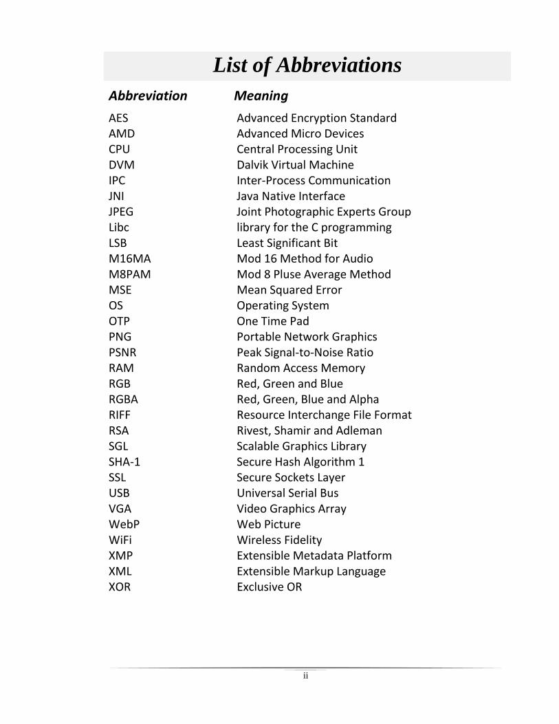
List of Abbreviations
Abbreviation Meaning
AES AMD CPU DVM IPC JNI JPEG Libc LSB M16MA M8PAM MSE OS OTP PNG PSNR RAM RGB RGBA RIFF RSA SGL SHA-1 SSL USB VGA WebP WiFi XMP XML XOR
Advanced Encryption Standard Advanced Micro Devices Central Processing Unit Dalvik Virtual Machine Inter-Process Communication Java Native Interface Joint Photographic Experts Group library for the C programming Least Significant Bit Mod 16 Method for Audio Mod 8 Pluse Average Method Mean Squared Error Operating System One Time Pad Portable Network Graphics Peak Signal-to-Noise Ratio Random Access Memory Red, Green and Blue Red, Green, Blue and Alpha Resource Interchange File Format Rivest, Shamir and Adleman Scalable Graphics Library Secure Hash Algorithm 1 Secure Sockets Layer Universal Serial Bus Video Graphics Array Web Picture Wireless Fidelity Extensible Metadata Platform Extensible Markup Language Exclusive OR
iii
Table of Contents Abstract i
List of Abbreviations ii
Table of Contents iii
List of Figures v
List of Tables vii
List of Algorithms viii
Chapter One
General Introduction
1.1 Introduction 1
1.2 Cryptography Versus Steganography 2
1.3 Android operating system 4
1.4 Literature Survey 6
1.5 Aim of Thesis 8
1.6 Thesis Layout 8
Chapter Two
Theoretical Background
2.1 Introduction 10
2.2 Data Security 10
2.2.1 Steganography 11
2.2.2 Cryptography 13
2.3 Algorithms of Data Security 15
2.3.1 Least Significant Bit (LSB) 16
2.3.2 Mod 16 Method for Audio algorithm (M16MA) 17
2.3.3 One Time Pad Algorithm (OTP) 18
2.3.4 Rivest, Shamir, and Adleman algorithm (RSA) 20
2.4 Cover File (WebP) image format 22
iv
2.5 Evaluation Tools 25
Chapter Three
The Proposed Steganography System
3.1 Introduction 26
3.2 Mod 8 Plus Average Method (M8PAM)
Steganography System
26
3.3 The Embedding Process 31
3.4 The Extraction Process 43
Chapter Four
User Interfaces and Experimental Results
4.1 Introduction 52
4.2 User Interfaces 53
4.3 The Experimental Results 61
4.3.1 The capacity of the cover file 61
4.3.2 Determine the central change value 64
4.3.3 Selection one of the pixel components (R, G or B) 66
4.3.4 The performance of the proposed system 67
Chapter Five
Conclusions And Suggestion For Future Work
5.1 Conclusions 72
5.2 Suggestions for Future Work 73
References
v
List of Figures
Figure Title Page
1.1 The Android layers 4
2.1 The Steganography System. 12
2.2 The Cryptography System. 14
2.3 The embedding process of the M16MA. 18
2.4 The extraction process of the M16MA. 18
2.5 The RIFF file header. 23
2.6 The WebP file header. 23
2.7 The WebP file with VP8X header. 24
2.8 The Alpha header. 25
3.1 The block diagram of the proposed steganography system. 27
3.2 Block diagram of the proposed embedding steganography
system.
28
3.3 Block diagram of the proposed extraction steganography
system.
30
3.4 The workflow of the operation on the WebP. 34
3.5 The integration between the layers. 35
3.6 Example about the getting indexes in the cover file. 36
3.7 Relation between the BGRA array, Array of locations and
the result of the proposed algorithm for selection locations.
37
3.8 Example about the generating a non-sequential indexes. 38
3.9 Example of redistributed process. 39
vi
3.10 The parameters of the random function, and the output of the
process.
40
3.11 The workflow of the registration process. 41
3.12 The workflow of the proposed system with the three layers. 42
3.13 The relation between the embedding process and the
extraction process.
44
3.14 The integration between layers to provide an integrated
extraction process.
45
3.15 The workflow of the layer one in the extraction process. 46
3.16 The example about the regenerate the original digits. 48
3.17 The parameters of the random function in extraction process. 49
3.18 Workflow of the proposed extraction process with the three
layers.
50
4.1 The start activity of the proposed system. 53
4.2 The new account activity. 54
4.3 The Select Option Activity. 55
4.4 The steganography types. 56
4.5 The list of Stickers. 56
4.6 The Embedding activity for the Pure Steganography. 57
4.7 The Embedding activity for the Secret key Steganography. 58
4.8 The Embedding activity for the Public key Steganography. 58
4.9 The image sharing popup. 59
4.10 The Extraction activity for Pure Steganography. 59
4.11 The Extraction activity for Secret Key Steganography. 60
4.12 The Extraction activity for Public Key Steganography. 60
vii
List of Tables
Tables Title Page
2.1 The difference between the WebP and the JPEG image
formats.
22
4.1 The samples of the stickers with maximum size of data that
allowed to embedded.
62
4.2 The value of central change with its amount of repetition
for the secret message.
65
4.3 The effect of adding the central change value for the stego
file.
65
4.4 The effect of the hiding the secret data inside (B, G or R). 66
4.5 The difference between the maximum capacity of the
proposed algorithm and the another algorithm.
68
4.6 The difference between the results of the the proposed
algorithm and the algorithm that used for comparison.
69
4.7 The results of the measures (MSE and PSNR) that used to
evaluate the system performance of the proposed algorithm.
70
4.8 Difference of increased size between the cover file and the
stego file.
71
viii
List of Algorithms
Algorithm Title Page
2.1 Implementation of the one-time pad encryption
method.
19
2.2 Implementation of the one-time pad decryption
method.
19
2.3 The processes of generate the public /private key. 21
2.4 Implementation of the RSA encryption method. 21
2.5 Implementation of the RSA decryption method. 21
3.1 Implementation of the embedding process. 29
3.2 Implementation of the extraction process. 31
3.3 The operations that occur on the secret message. 32
3.4 The operations that occur on the cover media. 33
3.5 The steps of the algorithm of selection locations. 37
3.6 The operations that occur on the extracted secret data. 47

Chapter One
General Introduction
Chapter One ----------------------------------------------------------------------------- General Introduction
1 | P a g e
Chapter One
General Introduction
1.1 Introduction
In the last years, the data security become more important issue for the
essential and sensitive data, therefore, access to these data by intruders must
be restricted and also impossible if necessary, in order to avoid the misuse
of this secret data or even to know any information that must remain as a
secret. So intruders are willing to exploit any vulnerability to obtain this data
whether it belongs to persons, companies, banks, organizations or
government institutions. For these reasons, the data security field is more
important and that must combine with any other fields which dealing with
sensitive and secret data.
There are two techniques that used to provide the data security features;
the first technique is the cryptography technique, this technique is most
widely used, it’s characterized by the conversion of secret data to un-
understandable data by encoding it, only the sender and the receiver can
decrypt this data by using a shared key. The cryptographers have developed
different methods and algorithms for the cryptography technique, because
many of the encryption algorithms are broken by using reverse engineering,
the field that deals with the methods of analysis of these algorithms is called
cryptanalysis, the weakness of the cryptography technique is that encrypted
data is suspected if it is observed by intruders. Therefore, there was the need
to use another technique. The second technique, the steganography
technique, it’s characterized by embedding the secret data inside the cover
file that can be any type of multimedia files (image, sound, video, etc.) or
protocols. In this technique the cover file can be viewed by the intruder, but
it is not possible to suspect that there is secret data inside it if the process of
Chapter One ----------------------------------------------------------------------------- General Introduction
2 | P a g e
the embedding professionally done efficient algorithms, the secret data will
restructure the cover file according to a particular algorithm, so that it is
possible to retrieve secret data from inside the cover file. The use of
steganography technique alone only in any system may not meet the
requirement of the data security, for example, secret information was sent to
a specific person, and this information was secured using the steganography
technique and was embedded in an image. If the computer of the receiver
was hacked by an intruder, so the computer was completely controlled by
the intruder as well as the files containing the secret data and the application
that extracts them, in which case the use of steganography technique alone
is not enough. Another example, is that someone wanted to send a secret
message to the police and any other person should not discover this message.
If this message is not properly secured then it may be attacked by intruders,
this secret message will be disclosed and changed to information serving the
intruders, and then re-sent with false information. For these reasons,
encryption of secret message and data hiding from unauthenticated usage is
very important.
1.2 Cryptography Versus Steganography
The design of a system combines the cryptography and steganography
techniques as a requirement to provide secure communication and data
transmission to ensure that secret data does not fall in hands of intruders. The
process of detecting encrypted data is more difficult than unencrypted data
that is embedded within a cover file. In this case, the intruder when
attempting to extract embedded data will encounter a large problem in
understanding this data because it is encoded using one of encryption
algorithm, when these two techniques are combined, the system becomes
more secure. If the steganography technique fails and the hidden data was
Chapter One ----------------------------------------------------------------------------- General Introduction
3 | P a g e
extracted, the data is still secured by cryptography technique [Mih12]. There
are many difference between the cryptography and steganography [Kha15]:
- Cryptography:
Known message is passed.
It alters the structure of the message.
Key is necessary.
Used to encode the message.
In this mostly text are used.
Attack on Cipher Text is called Cryptoanalysis.
Output are Cipher text.
- Steganography:
Unknown message is passed.
It does not alter the structure of the message.
Key is optional.
Used to hide the message.
Carrier can be any media file like Text, audio, image , video.
Attack on Stego Object is called Stegoanalysis.
Output are Stego File.
Algorithm of the combination technique[Kha15]:
Sender will provide the plain text and a key
Then an algorithm is used for encryption of the message.
Then this encrypted message or cipher text is embedded in an image
with the help of some algorithm to produce a Stegano Image and key
is option in this process.
Then the Stego image is transmitted for communication.
Then the receiver will perform the reverse processes. Receiver will
first extract the Cipher message form image using extraction
algorithm.
Chapter One ----------------------------------------------------------------------------- General Introduction
4 | P a g e
Then receiver will apply decryption algorithm and will provide key to
decrypt the cipher text.
The output will be the original plain text message.
1.3 Android operating system
The Android operating system was designed for mobile devices and
tablets, it is one of the most widely used operating systems for smartphones
today, the company that founded this operating system (OS) in the 2003
called the Android Incorporated (Inc.). Then in 2005 specifically, Google
acquired this operating system and launched it in 2007. This OS based on the
Linux kernel, has its own virtual machine and is used to execute its
applications. The advantages of the Android OS is the continuous
improvement on this OS by google Inc. addition to the higher speed to access
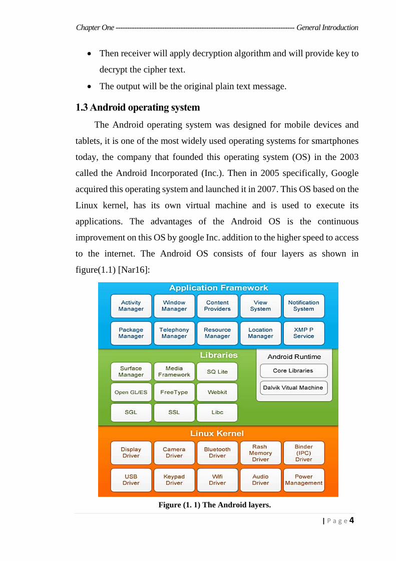
to the internet. The Android OS consists of four layers as shown in
figure(1.1) [Nar16]:
Figure (1. 1) The Android layers.
Chapter One ----------------------------------------------------------------------------- General Introduction
5 | P a g e
- Linux Kernel: This layer does not provide the ability to interact with
developers and users, it provides compatibility between the hardware
component and upper layers.
- Libraries: Set of libraries that written in the native C/C++ language that
support various components (SQLite, OpenGL, Wib Kit, etc.),
additionally it provides the Android Runtime, it provides the Dalvik
Virtual Machine (DVM), that used to execute its applications.
- Application Framework: This layer provides services (Activity-
Manager, Telephony-Manager, etc.) to developers and is of a higher level
for applications in the form of Java.
- Applications: it provides the interaction between the device and the user.
Android is a sophisticated Operating System supporting a great
number of applications in Smart Phones. Android mainly deals with the
apps which are used in real-time[Kas14].
Android Platform Differences[Kas14].
Android is hailed as "the first finish, open, and free portable stage."[Kas14].
- Complete: The creators took a thorough methodology when they created
the Android stage. They started with a safe working framework and
assembled a strong programming structure on top that takes into account
rich provision advancement good fortunes.
- Open: The Android stage is given through open source permitting.
Designers have remarkable access to the handset characteristics when
creating provisions.
- Free: Android provisions are allowed to create. There are no authorizing
or sovereignty charges to create on the stage. No obliged enrolment
charges. No obliged testing expenses. No obliged marking or
accreditation charges. Android requisitions could be circulated and
popularized in a mixed bag of ways.
Chapter One ----------------------------------------------------------------------------- General Introduction
6 | P a g e
1.4 Literature Survey
- Thenmozhi and Chandrasekran [The13] presented a novel technique
for Image steganography based on DWT, where DWT is used to transform
original image (cover image) from spatial domain to frequency domain.
Discussed the chaotic system, and its advantages for achieving the
encryption of data. Applied the henon mapping (chaos) on the secret image
and performed the two dimensional Discrete Wavelet Transform (2-D
DWT) on the cover image of size M × N. improved the Image quality by
preserving the wavelet coefficients in the low frequency sub band.
Experimental results showed that the algorithm has a high capacity and a
good invisibility.
- Debiprasad and Kousik [Deb14] proposed an approach of building a
secure data hiding technique in digital images using secure LSB technique
for image steganography. The proposed technique uses host image files in
spatial domain to hide the presence of sensitive information. A 3-3-2 LSB
insertion method has been used for image steganography. Experimental
results show a substantial improvement in the PSNR and Image value of
the proposed technique over the base technique of 3-3-2 LSB insertion.
- Zhiwei [Zhi14] discussed image steganography combined with
preprocessing of DES encryption. When transmitting the secret
information, firstly, encrypt the information intended to hide by DES
encryption was encrypted, and then was written in the image through the
LSB steganography. Improved the Encryption algorithm lowest matching
performance between the image and the secret information by changing the
statistical characteristics of the secret information to enhance the anti-
detection of the image steganography. Experimental results showed that the
anti-detection robustness of image steganography combined with
preprocessing of DES encryption was found much better than the way using
LSB steganography algorithms directly.
Chapter One ----------------------------------------------------------------------------- General Introduction
7 | P a g e
- Manjula and Ajit [Man15] proposed a method to embed a color secret
image (payload) into a color cover image. The proposed technique takes
eight bits of secret data at a time and put them in LSB of Red, Green and
Blue (RGB) pixel value of the cover image in 2, 3,3 order respectively.
Such that out of eight (08) bits of message five (05) bits are inserted in R
and G pixel and remaining three (03) bits are inserted in B pixel. This
method provides clearly better results compared with 3,3,2 method.
- Mohammed and Atef [Moh16] proposed a novel gray scale
steganographic method for information security. It based on the idea of
image segmentation to give an improved steganography method for
embedding secret message bit in least significant bits of random pixel in a
random area within the grayscale cover image. Experimental results show
that, the proposed method satisfied most of the security requirements,
explained adaptability of grayscale cover image as a host to hide the secret
messages and improved the data hiding capacity of host image by utilizing
all the pixels.
- Mehdi and Ainuddin [Meh17] proposes a new data hiding method
that increases visual quality and payload, as well as maintains
steganographic security. The proposed scheme consists of two novel
methods of parity-bit pixel value difference (PBPVD) and improved
rightmost digit replacement (iRMDR). It partitions the cover image into
two non-overlapping pixel blocks. The difference value between pixels in
each block is used to determine the selection of PBPVD and iRMDR.
According to the experimental results, the iRMDR method attains the best
closest stego-pixels for good visual imperceptibility by resolving the region
inconsistency problem in the existing method.
Chapter One ----------------------------------------------------------------------------- General Introduction
8 | P a g e
1.5 Aim of Thesis
This thesis aims to design and implements steganography system by
using proposed algorithm for embedding secret message within WebP
image. Main goal of this thesis is to send message secretly such that an
unknown person should be not able to extract the hidden message.
The objectives are as follows:
1. To understand how Cryptography and Steganography techniques
with proposed algorithm that named Mod 8 Plus Average Method
(M8PAM) are implemented.
2. Implements three layers to improve the security of the system.
3. To use new image format that named WebP format also Known as
Stickers as a cover file.
4. To explain how the experimental results that used to evaluate the
system performance are used.
1.6 Thesis Layout
This thesis was organized into five chapters. Including the first
chapter, which is an introduction to the basic concepts of data security as
well as operating system Android and the vulnerabilities that facing users
in addition to the objectives of this thesis, the rest chapters organized as
follows:
1. Chapter Two: Entitled "Theoretical Background of Data Security"
The theoretical basis of the data security was described in this chapter,
beside the main two techniques (Steganography, Cryptography) that used
in this thesis. This chapter contains a simple explanation of all the
concepts mentioned in this thesis.
Chapter One ----------------------------------------------------------------------------- General Introduction
9 | P a g e
2. Chapter Three: Entitled " The Proposed Steganography System"
The practical part of this thesis is described in this chapter in detail. This
chapter includes the stages of designing the system in successive steps
that resulted in the required system. In addition to explain the designed
and applied algorithms.
3. Chapter Four: Entitled " User Interfaces and Experimental Results"
The user designed interfaces to perform the functions of the system were
presented in this chapter, as well as the experimental results of system
performance compared with pre-proposed systems by other researchers.
4. Chapter Five: Entitled " Conclusions and Future Work"
The conclusions of the thesis of the proposed system have been presented
in this chapter in summary, in addition to the future work that may be
done in the future to develop the proposed system.
Chapter Two
Theoretical Background
Chapter Two ------------------------------------------------------------------------- Theoretical Background
10 | P a g e
Chapter Two
Theoretical Background
2.1 Introduction
Recently, studies on the importance of providing different ways for data
security has increased because of increasing attempts of intruding on those
data, whether transmitted through the Internet or were stored. In this chapter,
the theoretical concepts that related to the data security that represent the
thesis work were presented, by explaining all the aspects that have been dealt
with by the proposed system.
The following sections are organized as follow: section (2.2) the
security issues are presented in details along with the techniques that used in
the data security; section (2.3) the network security techniques are presented;
finally, some of methods that are used to evaluate the system works are
presented in the section (2.4).
2.2 Data Security
The importance of information security have emerged in recent years,
due to the spread of computing system in all aspects of life. Therefore,
researchers focused in this area on how to keep this information from
exposure to theft, loss or change. It has become the field of information
security of the most important areas that are being studied and developed,
and is defined as “to provide protection for any automated system that
specializes in managing, storing and providing information" [Wil15].
The properties that must be provided by information security to the
information managed by the system, which includes [Wit16]:
Confidentiality: Information is available only to authorized persons.

Chapter Two ------------------------------------------------------------------------- Theoretical Background
11 | P a g e
Integrity: Unauthorized changes to the Information is reject.
Availability: Information must be available all the time to people
authorized to access them when needed.
In order for the system to achieve the above properties, some measures
must be taken, these measures are classified as follows [Die11]:
Prevention: Measures taken to protect information from any damage
or change.
Detection: Measures taken to detect the damage in information, how
it was damaged and what is causing the damage or change.
Reaction: Measures taken to repair the damaged information or to
restore it to pre-damage or change.
There are many techniques that are developed to achieve data security,
the most common techniques are cryptography and steganography [Kha14].
Each technique is applied separately, each with its own weaknesses and
strengths, but when the two technologies are combined, the system becomes
more powerful. Each technique will be explained in detail in the following
section[Hay14];
2.2.1 Steganography
One of the most important data security techniques, which are not
limited to being science but goes even further to be the art of embedding of
secret data [Hus04]. The term of steganography that derived from two words
in Greek "stegano-graphy" which means, "Perform the writing in secret
form", steganography is the embed of "the secret data" which can be any
form of digital data that represented in the computer system (message,
image, sound and etc.) within another digital form for example (image, video
and etc.) [Mic12].
The steganography system works as follow, the steganography process
consists of two algorithms, the embedding and extraction algorithm also this
which represent the processes of the system and the other elements represent
Chapter Two ------------------------------------------------------------------------- Theoretical Background
12 | P a g e
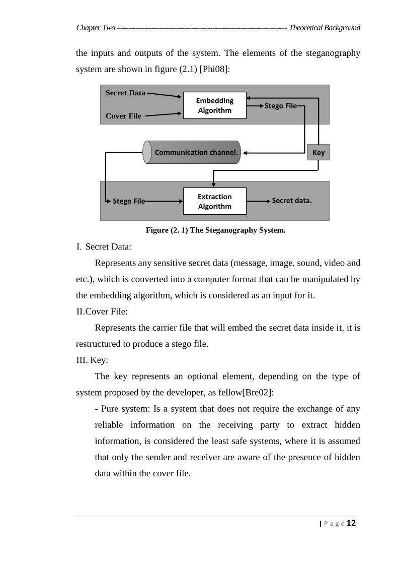
the inputs and outputs of the system. The elements of the steganography
system are shown in figure (2.1) [Phi08]:
Figure (2. 1) The Steganography System.
I. Secret Data:
Represents any sensitive secret data (message, image, sound, video and
etc.), which is converted into a computer format that can be manipulated by
the embedding algorithm, which is considered as an input for it.
II. Cover File:
Represents the carrier file that will embed the secret data inside it, it is
restructured to produce a stego file.
III. Key:
The key represents an optional element, depending on the type of
system proposed by the developer, as fellow[Bre02]:
- Pure system: Is a system that does not require the exchange of any
reliable information on the receiving party to extract hidden
information, is considered the least safe systems, where it is assumed
that only the sender and receiver are aware of the presence of hidden
data within the cover file.
Communication channel.
Secret Data
Cover File
Embedding Algorithm Stego File
Stego File Extraction Algorithm
Secret data.
Key
S
Chapter Two ------------------------------------------------------------------------- Theoretical Background
13 | P a g e
- Secret Key system: This key is used in the process of embedding the
secret data, and it’s necessary for the process of extracting secret data
at the receiver side.
- The public key system: In this system, each party has two keys. The
first one is public and known for all, and the second is private. The first
is used in the embedding process at the sender side and the second is
used in the extraction process at the receiver side.
IV. Stego File:
Represent the output of the embedding algorithm and the input of the
extraction algorithm, it represents the cover file after the secret data has been
hidden inside it.
V. Embedding algorithm:
The embedding algorithm is responsible for performing the process of
hiding the secret data within the cover file, it is the most important of the two
algorithms. The algorithm must be carefully implemented to ensure that
secret data was transmitted to the receiving end without being noticed by
intruder, where this point represents the main goal of the steganography
system.
VI. Extraction algorithm:
The extraction algorithm becomes easier than the embedding algorithm
after it is executed, because it is simply the reverse of the embedding
algorithm. The processing of this algorithm takes the resulting file from the
embedding process and then extracts the secret data. The secret data must be
restricted to the end user.
2.2.2 Cryptography
Cryptography is the conversion of secret data from an understandable
formula to another incomprehensible and indistinguishable formula [Tsa05].
Chapter Two ------------------------------------------------------------------------- Theoretical Background
14 | P a g e
The term of cryptography that derived from two words in Greek "
kryptos-graphy" which means, "secret writing" [Kav10].
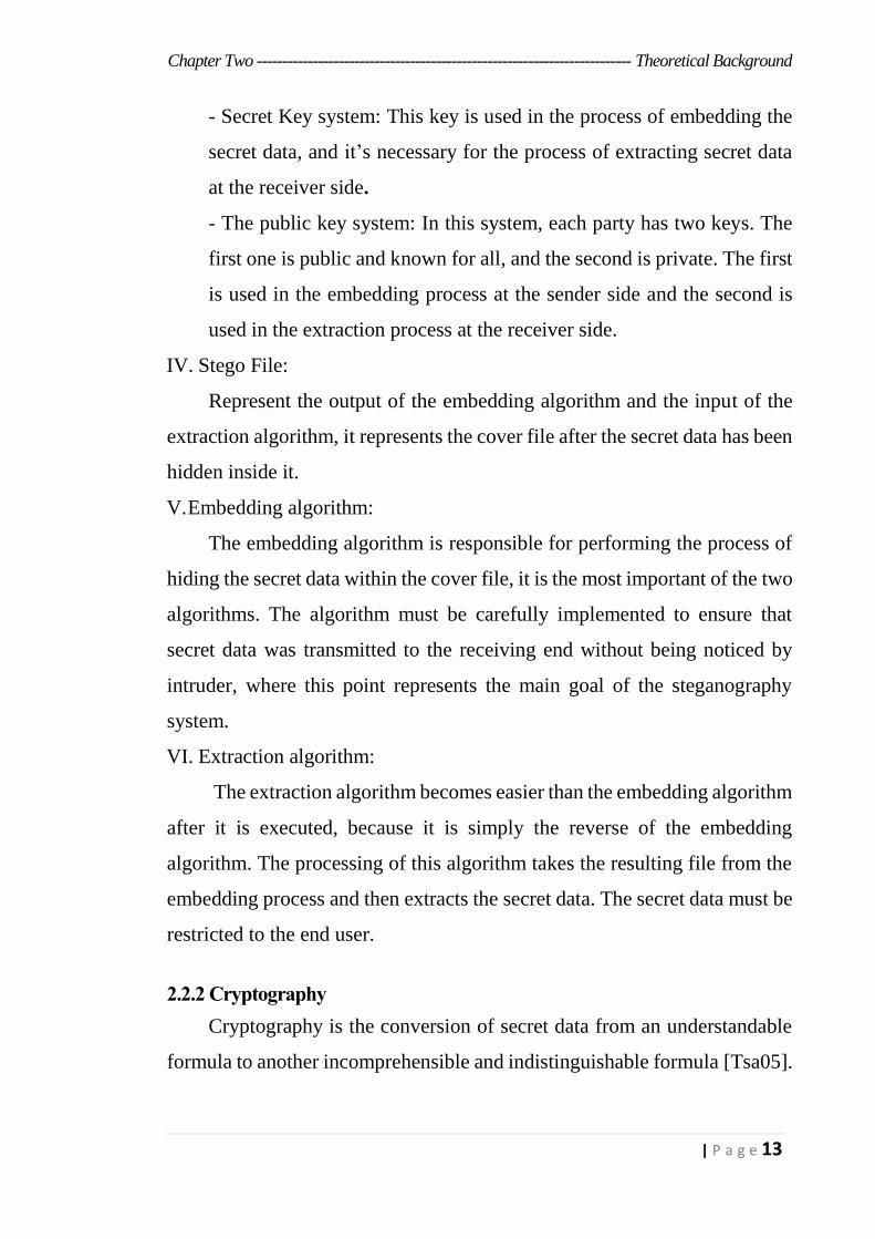
The cryptography system works as follow; the cryptography process
consists of two algorithms, the encryption and decryption algorithms they
represent the processes of the system and the other elements represent the
inputs and outputs of the system. Figure (2.2) shows the cryptography
system,
Figure (2. 2) The Cryptography System.
the cryptography elements will be describe in details [Kha15]:
I. Plain Text )Plain Data(:
Represents original secret data (message, image, sound, video and etc.),
which is converted into a computer format that can be manipulated by the
encryption algorithm, which is considered as an input for it.
II. Cipher Text ) Cipher Data(:
represent the output of the encryption algorithm and the input of the
decryption algorithm, it represent the secret file after encrypting it and it’s in
a coded format.
III. Key:
The key represents a necessary element in cryptography technique,
there are more than one type of key used depending on the type of
Encryption Algorithm
Plain Text or Plain Data
Cipher Text or Cipher Data
Decryption Algorithm
Key
Communication channel.
Key
Sender
Receiver

Chapter Two ------------------------------------------------------------------------- Theoretical Background
15 | P a g e
cryptography system used [Ven10]:
- Secret Key System: This key is used in the process of encrypting the
secret data and in the process of decrypting secret data at the receiver
side.
- Public Key System: In this system, each party has two keys. The first
one is public and known for all, and the second is private. The first is
used in the encryption process at the sender side. And the second is
used in the decryption process at the receiver side.
IV. Encryption algorithm:
The encryption algorithm is responsible for performing the process of
encoding the secret data file, the secret data after the encryption process
becomes indistinguishable.
V. Decryption algorithm:
The decryption algorithm is used to convert confidential data that has
been encrypted using the encryption algorithm from an incomprehensible
formula to a comprehensible formula. The processing of this algorithm takes
the resulting file from the encryption process that represent the cipher data
and then decoding it. The decoding of the secret data must be restricted to
the end user.
2.3 Algorithms of Data Security
The algorithms that provide data security in both the steganography and
cryptography techniques were initially applied separately, but there was a
need to combine the two technologies to provide the integration of their
benefits.
There are many different algorithms that have been applied by the two
techniques which were explained in detail previously. Two algorithms are
presented on each of the techniques that described;
Chapter Two ------------------------------------------------------------------------- Theoretical Background
16 | P a g e
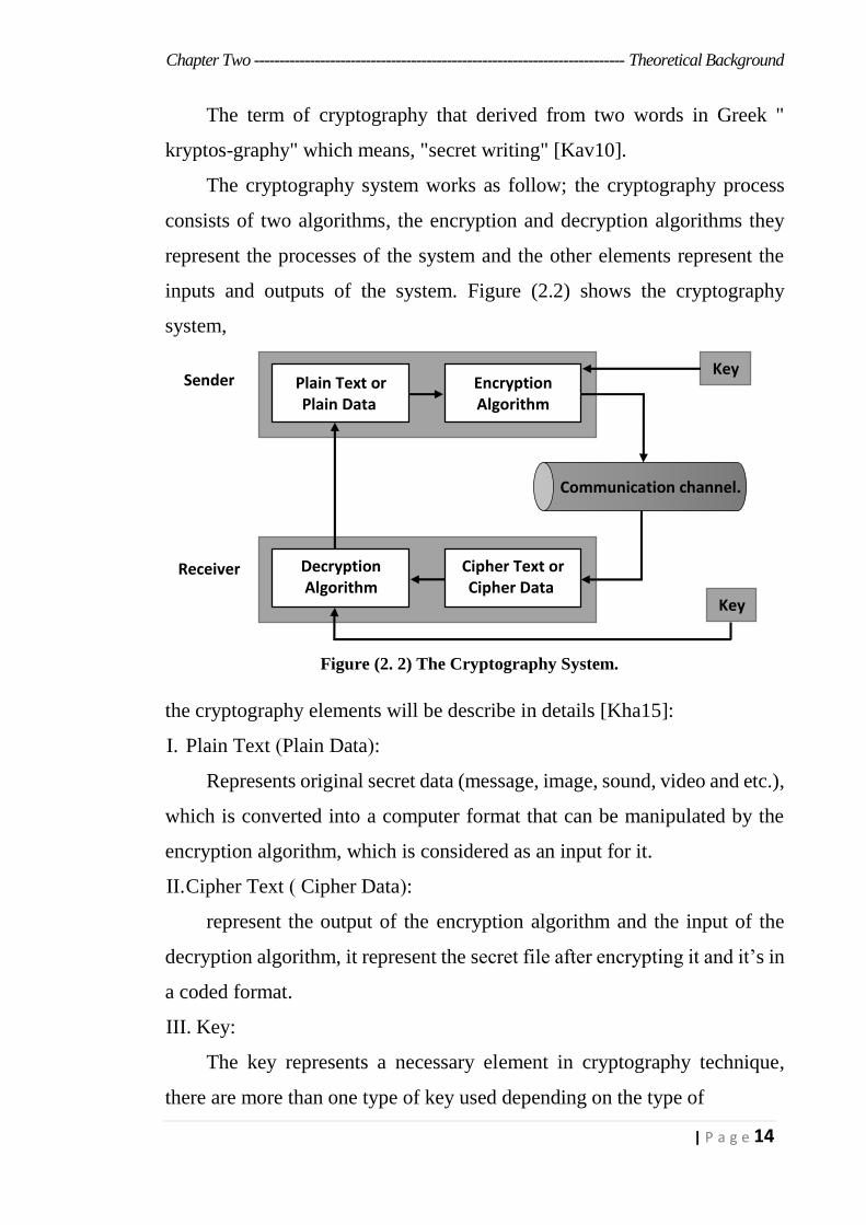
-Steganography: The Least Significant Bit algorithm (LSB) which is
one of the most famous algorithms that used in the steganography technique,
Mod 16 Method for Audio algorithm (M16MA) which is one of the newest
algorithms that is used in the steganography technique.
-Cryptography: The One Time Pad Algorithm (OTP) the most famous
algorithms that used in the cryptography technique and Rivest, Shamir, and
Adleman algorithm (RSA) that used in the public-key cryptography.
2.3.1 Least Significant Bit (LSB):
It is one of the most common algorithms used in steganography
technology because it has many advantages, the simplicity of its
implementation of the embedding process is compared to other algorithms,
the ability to hide one, two or three bits of secret information inside the
carrier medium, when the number of hidden bits increases within the cover
media, the capacity of hiding the secret information increases and the cover
file becomes more distorted. If a multimedia is used as a cover file in the
LSB algorithm, the eye or human hearing cannot distinguish the change in
the stego file, because the cover file matches the stego file [Rah14].
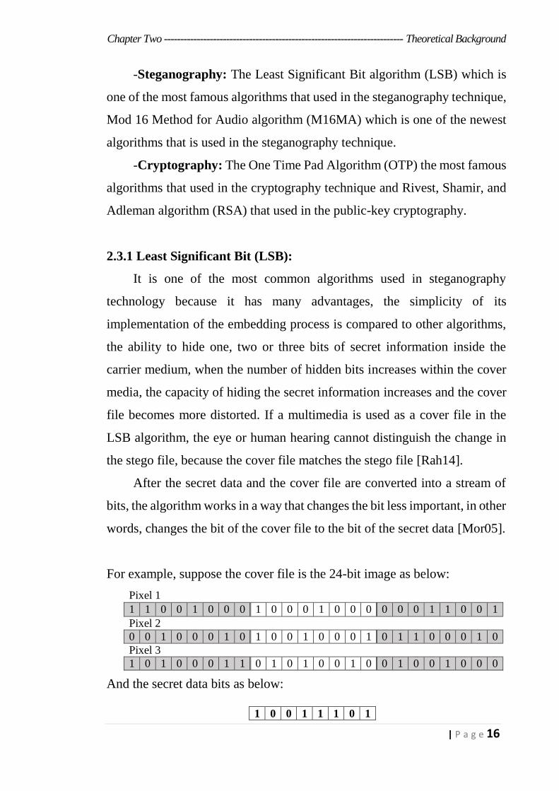
After the secret data and the cover file are converted into a stream of
bits, the algorithm works in a way that changes the bit less important, in other
words, changes the bit of the cover file to the bit of the secret data [Mor05].
For example, suppose the cover file is the 24-bit image as below:
Pixel 1
1 1 0 0 1 0 0 0 1 0 0 0 1 0 0 0 0 0 0 1 1 0 0 1
Pixel 2
0 0 1 0 0 0 1 0 1 0 0 1 0 0 0 1 0 1 1 0 0 0 1 0
Pixel 3
1 0 1 0 0 0 1 1 0 1 0 1 0 0 1 0 0 1 0 0 1 0 0 0
And the secret data bits as below:
1 0 0 1 1 1 0 1
Chapter Two ------------------------------------------------------------------------- Theoretical Background
17 | P a g e
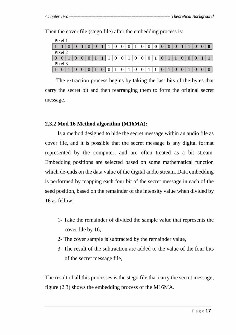
Then the cover file (stego file) after the embedding process is:
Pixel 1
1 1 0 0 1 0 0 1 1 0 0 0 1 0 0 0 0 0 0 1 1 0 0 0
Pixel 2
0 0 1 0 0 0 1 1 1 0 0 1 0 0 0 1 0 1 1 0 0 0 1 1
Pixel 3
1 0 1 0 0 0 1 0 0 1 0 1 0 0 1 1 0 1 0 0 1 0 0 0
The extraction process begins by taking the last bits of the bytes that
carry the secret bit and then rearranging them to form the original secret
message.
2.3.2 Mod 16 Method algorithm (M16MA):
Is a method designed to hide the secret message within an audio file as
cover file, and it is possible that the secret message is any digital format
represented by the computer, and are often treated as a bit stream.
Embedding positions are selected based on some mathematical function
which de-ends on the data value of the digital audio stream. Data embedding
is performed by mapping each four bit of the secret message in each of the
seed position, based on the remainder of the intensity value when divided by
16 as fellow:
1- Take the remainder of divided the sample value that represents the
cover file by 16,
2- The cover sample is subtracted by the remainder value,
3- The result of the subtraction are added to the value of the four bits
of the secret message file,
The result of all this processes is the stego file that carry the secret message,
figure (2.3) shows the embedding process of the M16MA.

Chapter Two ------------------------------------------------------------------------- Theoretical Background
18 | P a g e
Figure (2.3) the embedding process of the M16MA.
The extraction process begins by selection the locations that have been
hidden the secret bits inside it, and then extracting the secret bits by reversing
the embedding process, figure (2.4) shows the extraction process of the
M16MA [Sou11].
Figure (2.4) the extraction process of the M16MA.
2.3.2 One Time Pad Algorithm (OTP):
One-time pad encryption method was invented in the beginning of the
nineteenth century, it was derived from the Vernam encryption
method[Nic09]. It's a binary stream encryption, this method produces
ciphertext by combining the plaintext and the key, the exclusive OR (XOR)
between the key and the plaintext was implemented to produce the ciphertext
or between the key and the ciphertext to produce the plaintext, the one-time
pad encryption method unbreakable if it met the following
conditions[Mil17]:
- Length of the key as the length of the plaintext.
36
4= 0100
36 Mod 16 = 4
Intensity of Stego data
Extracted Message
34
34 – 2 = 32
36
4= 0100
Intensity of Cover data
34 Mod 16 = 2
The Message to
be embedded
Intensity of Stego data
32 + 4 = 36
Chapter Two ------------------------------------------------------------------------- Theoretical Background
19 | P a g e
- The key must generate randomly.
- The key must be valid for use only once.
Using exclusive-or, leads to make the one-time pad method more
simple and does not consume much computational time, so to develop this
method and make it more complex, the changes that have been applied to
the method are the addition of the use of the 9’s complement and then the
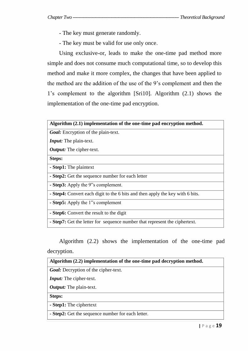
1’s complement to the algorithm [Sri10]. Algorithm (2.1) shows the
implementation of the one-time pad encryption.
Algorithm (2.1) implementation of the one-time pad encryption method.
Goal: Encryption of the plain-text.
Input: The plain-text.
Output: The cipher-text.
Steps:
- Step1: The plaintext
- Step2: Get the sequence number for each letter
- Step3: Apply the 9‟s complement.
- Step4: Convert each digit to the 6 bits and then apply the key with 6 bits.
- Step5: Apply the 1‟s complement
- Step6: Convert the result to the digit
- Step7: Get the letter for sequence number that represent the ciphertext.
Algorithm (2.2) shows the implementation of the one-time pad
decryption.
Algorithm (2.2) implementation of the one-time pad decryption method.
Goal: Decryption of the cipher-text.
Input: The cipher-text.
Output: The plain-text.
Steps:
- Step1: The ciphertext
- Step2: Get the sequence number for each letter.

Chapter Two ------------------------------------------------------------------------- Theoretical Background
20 | P a g e
- Step3: Convert each digit to the 6 bits and then apply the key with 6 bits.
- Step4: Apply the 1‟s complement .
- Step5: Convert the result to the digit.
- Step6: Apply the 9‟s complement.
- Step7: Get the letter for sequence number, that represent the plaintext.
2.3.3 Rivest, Shamir, and Adleman algorithm (RSA):
The cryptographic algorithms using the key is divided into two types,
cryptosystem by using symmetric-key and cryptosystem by using
asymmetric-key. In the first type; one key is used for the encryption process
as well as the decryption process and in the second type; one key is used for
the encryption process and another key is different from the first one in the
decryption process, one of these keys is a public key and the other is a private
key [Asw14].
One of the most common asymmetric-key algorithms is an algorithm
announced in 1977 by three researchers, Ron Rivest, Adi Shamir and
Leonard Adleman, this algorithm named as RSA algorithm based on the
names of their discoverers [Asm16].
RSA used for (key exchange, digital signatures and data encryption),
the strength of the RSA algorithm comes from its mathematical behavior by
determining the following points:
1) The simple calculation processes for large numbers.
2) The difficult processes for finding the prime factor for those
numbers.
3) They also deal with numbers consisting of hundreds of digits.
The first step in the RSA algorithm, create the pair keys that represent
the public /private key [Ven10]. Algorithm (2.3) shows the processes of the
RSA to generate the public /private key.
Chapter Two ------------------------------------------------------------------------- Theoretical Background
21 | P a g e
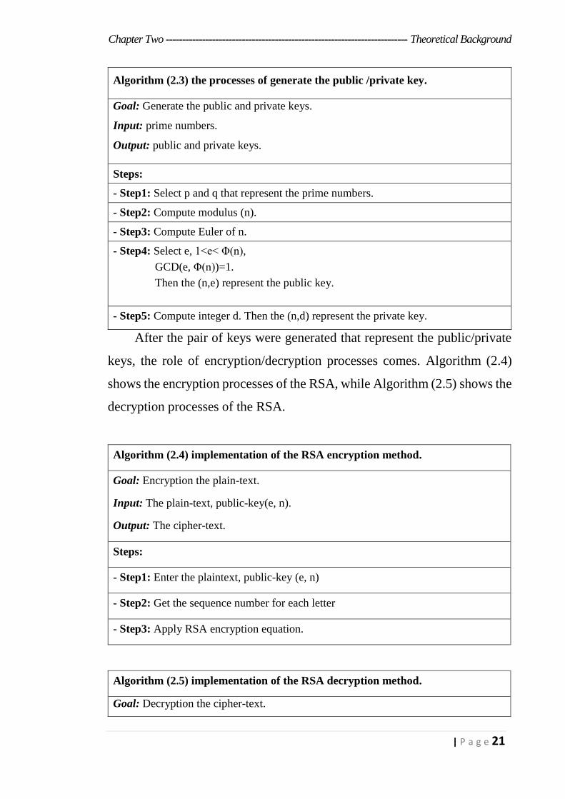
Algorithm (2.3) the processes of generate the public /private key.
Goal: Generate the public and private keys.
Input: prime numbers.
Output: public and private keys.
Steps:
- Step1: Select p and q that represent the prime numbers.
- Step2: Compute modulus (n).
- Step3: Compute Euler of n.
- Step4: Select e, 1<e< Φ(n),
GCD(e, Φ(n))=1.
Then the (n,e) represent the public key.
- Step5: Compute integer d. Then the (n,d) represent the private key.
After the pair of keys were generated that represent the public/private
keys, the role of encryption/decryption processes comes. Algorithm (2.4)
shows the encryption processes of the RSA, while Algorithm (2.5) shows the
decryption processes of the RSA.
Algorithm (2.4) implementation of the RSA encryption method.
Goal: Encryption the plain-text.
Input: The plain-text, public-key(e, n).
Output: The cipher-text.
Steps:
- Step1: Enter the plaintext, public-key (e, n)
- Step2: Get the sequence number for each letter
- Step3: Apply RSA encryption equation.
Algorithm (2.5) implementation of the RSA decryption method.
Goal: Decryption the cipher-text.
Chapter Two ------------------------------------------------------------------------- Theoretical Background
22 | P a g e
Input: The cipher-text, private-key(d, n).
Output: The plain-text.
Steps:
- Step1: Enter the ciphertext, private -key (e, n)
- Step2: Apply RSA decryption equation. Then get the letter for sequence number,
that represent the plaintext.
2.4 Cover File (WebP) image format
The cover file is the file that carries the secret data; its different
according to the algorithm used in the steganography technique, therefore, a
cover file must not be affected by the secret data that is embedded inside it.
It also has the capability to embed as much secret data as possible [Cha13].
WebP extension can be used as a cover file, in order to make the web browser
more rapid, google has developed a new image format in 2010, so that the
size of these images format is small while maintaining image quality, this
format is the WebP image format. The WebP image is less size than the jpeg
image format by 25-34% and less size than the png image format by 28%
[Tre12].
The main purpose of developing the WebP image format, is that 65%
of the multimedia that consuming Internet speed is an image, so there is a
need to develop image extension with fewer size of traditional images while
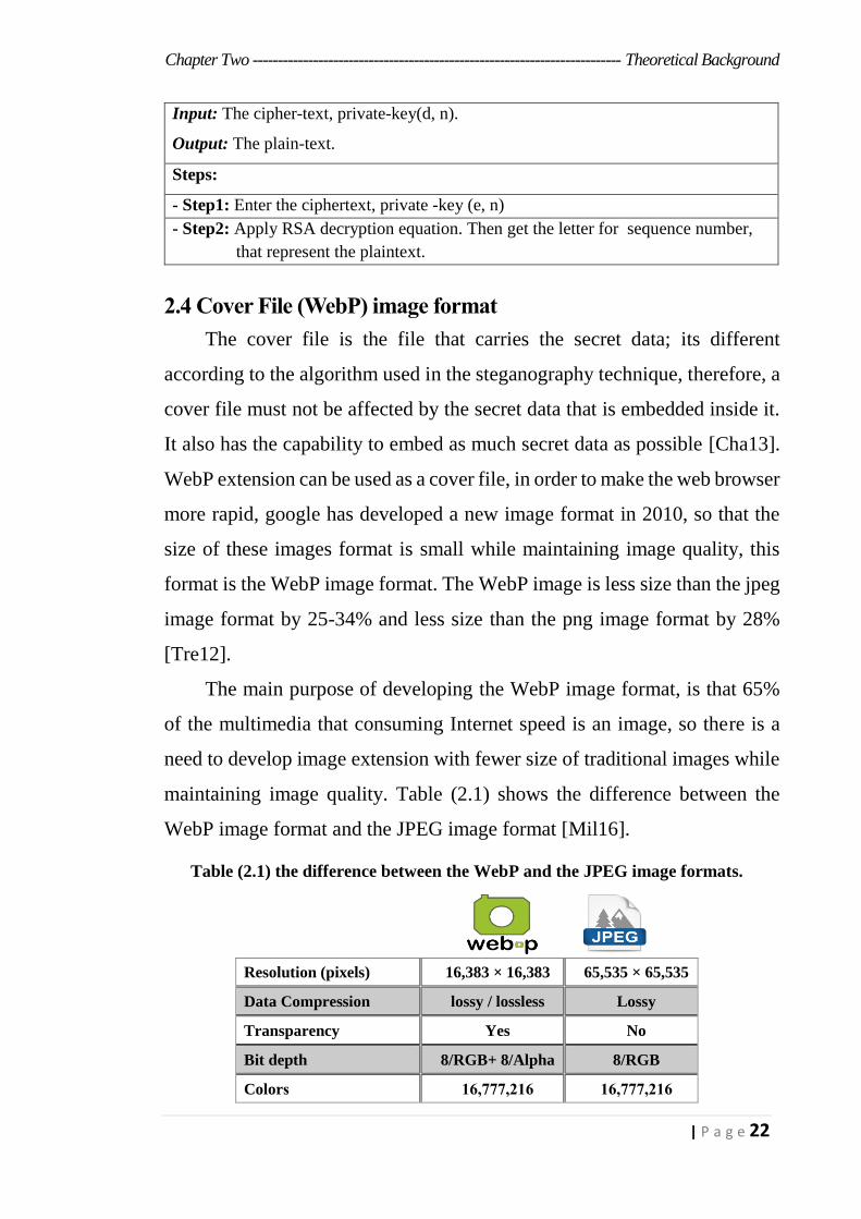
maintaining image quality. Table (2.1) shows the difference between the
WebP image format and the JPEG image format [Mil16].
Table (2.1) the difference between the WebP and the JPEG image formats.
Resolution (pixels) 16,383 × 16,383 65,535 × 65,535
Data Compression lossy / lossless Lossy
Transparency Yes No
Bit depth 8/RGB+ 8/Alpha 8/RGB
Colors 216,777,16 216,777,16
Chapter Two ------------------------------------------------------------------------- Theoretical Background
23 | P a g e
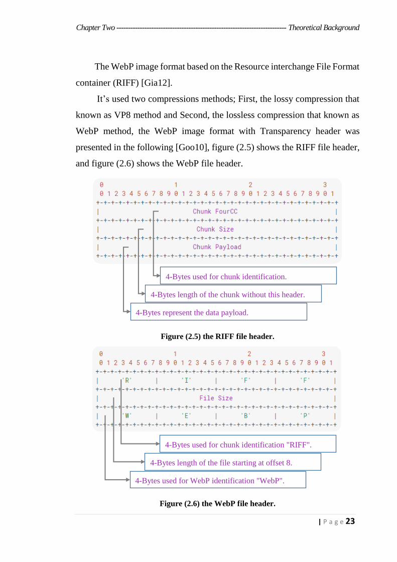
The WebP image format based on the Resource interchange File Format
container (RIFF) [Gia12].
It’s used two compressions methods; First, the lossy compression that
known as VP8 method and Second, the lossless compression that known as
WebP method, the WebP image format with Transparency header was
presented in the following [Goo10], figure (2.5) shows the RIFF file header,
and figure (2.6) shows the WebP file header.
Figure (2.5) the RIFF file header.
Figure (2.6) the WebP file header.
4-Bytes used for chunk identification.
4-Bytes length of the chunk without this header.
4-Bytes represent the data payload.
4-Bytes used for chunk identification "RIFF".
4-Bytes length of the file starting at offset 8.
4-Bytes used for WebP identification "WebP".
Chapter Two ------------------------------------------------------------------------- Theoretical Background
24 | P a g e
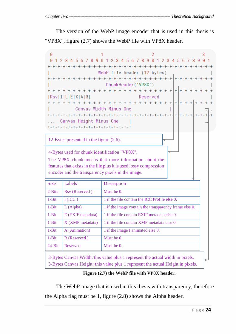
The version of the WebP image encoder that is used in this thesis is
"VP8X", figure (2.7) shows the WebP file with VP8X header.
Figure (2.7) the WebP file with VP8X header.
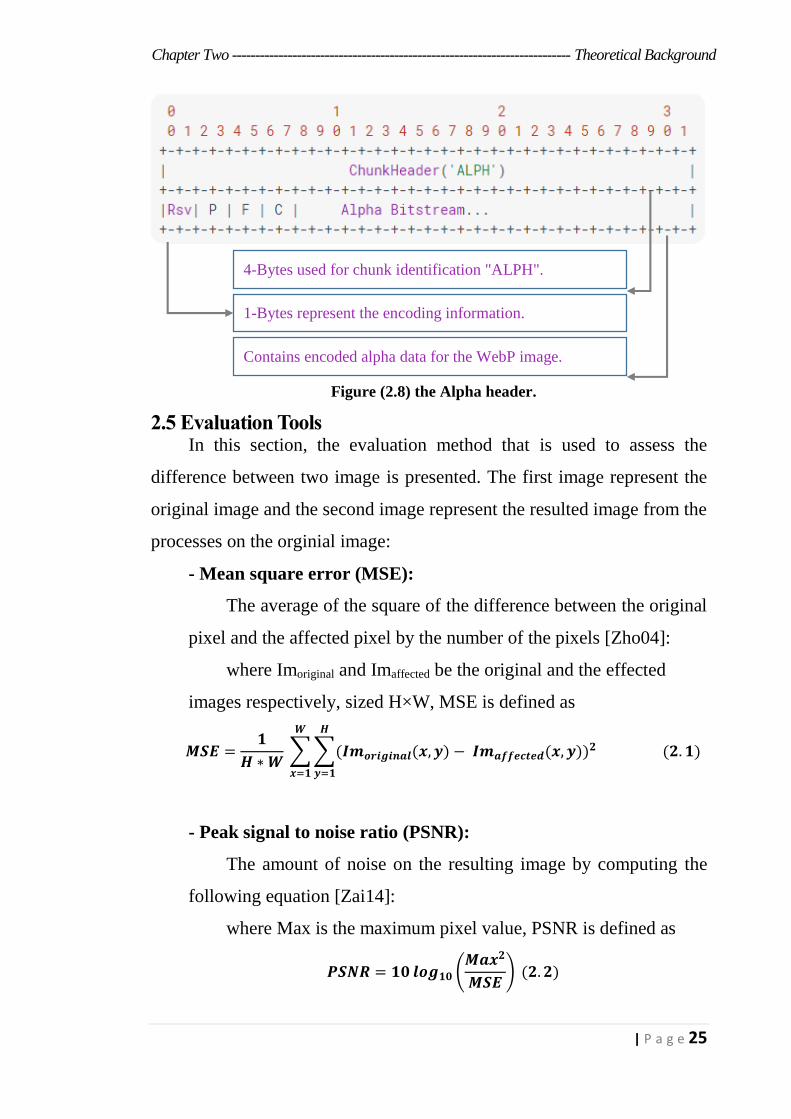
The WebP image that is used in this thesis with transparency, therefore
the Alpha flag must be 1, figure (2.8) shows the Alpha header.
12-Bytes presented in the figure (2.6).
4-Bytes used for chunk identification "VP8X".
The VP8X chunk means that more information about the
features that exists in the file plus it is used lossy compression
encoder and the transparency pixels in the image.
Size Labels Discerption
2-Bits Rsv (Reserved ) Must be 0.
1-Bit I (ICC ) 1 if the file contain the ICC Profile else 0.
1-Bit L (Alpha) 1 if the image contain the transparency frame else 0.
1-Bit E (EXIF metadata) 1 if the file contain EXIF metadata else 0.
1-Bit X (XMP metadata) 1 if the file contain XMP metadata else 0.
1-Bit A (Animation) 1 if the image I animated else 0.
1-Bit R (Reserved ) Must be 0.
24-Bit Reserved Must be 0.
3-Bytes Canvas Width: this value plus 1 represent the actual width in pixels.
3-Bytes Canvas Height: this value plus 1 represent the actual Height in pixels.
Chapter Two ------------------------------------------------------------------------- Theoretical Background
25 | P a g e
Figure (2.8) the Alpha header.
2.5 Evaluation Tools In this section, the evaluation method that is used to assess the
difference between two image is presented. The first image represent the
original image and the second image represent the resulted image from the
processes on the orginial image:
- Mean square error (MSE):
The average of the square of the difference between the original
pixel and the affected pixel by the number of the pixels [Zho04]:
where Imoriginal and Imaffected be the original and the effected
images respectively, sized H×W, MSE is defined as
𝑴𝑺𝑬 =𝟏
𝑯 ∗ 𝑾 ∑ ∑(𝑰𝒎𝒐𝒓𝒊𝒈𝒊𝒏𝒂𝒍(𝒙, 𝒚) − 𝑰𝒎𝒂𝒇𝒇𝒆𝒄𝒕𝒆𝒅(𝒙, 𝒚))𝟐
𝑯
𝒚=𝟏
𝑾
𝒙=𝟏
(𝟐. 𝟏)
- Peak signal to noise ratio (PSNR):
The amount of noise on the resulting image by computing the
following equation [Zai14]:
where Max is the maximum pixel value, PSNR is defined as
𝑷𝑺𝑵𝑹 = 𝟏𝟎 𝒍𝒐𝒈𝟏𝟎 (𝑴𝒂𝒙𝟐
𝑴𝑺𝑬) (𝟐. 𝟐)
4-Bytes used for chunk identification "ALPH".
1-Bytes represent the encoding information.
Contains encoded alpha data for the WebP image.
Chapter Three
The Proposed
Steganography System
Chapter Three --------------------------------------------------------- The Proposed Steganography System
26 | P a g e
Chapter Three
The Proposed Steganography System
3.1 Introduction
In this chapter, the design of information security based on
steganography technique by using a proposed algorithm that named as Mod
8 Plus Average Method (M8PAM) is designed to hide the secret message
inside the newest images format used in the internet, this image format
known as a WebP format, also Known as the stickers for chatting
applications. The M8PAM algorithm is applied on three layers.
The first layer, to select the locations of the cover file where the secret
data will be hidden in it in a non-sequential manner based on a proposed
algorithm. This layer can be applied alone. The second layer, recoding the
secret data by changing the sequence of secret message bits based on the
random sequence generation function. At this layer, the secret data is
embedded and extracted using a symmetric key on both sides. The symmetric
key affects the seed number that used in the random sequence generation
function and this layer can't be applied without the first layer. The third layer
is to hide the secret data at the sending end using the public key and to extract
the secret data at the receiving end using the private key and this layer can't
be applied without the second layer and the first layer.
In this chapter, the proposed steganography system are presented with
implementation requirement and the steps taken to the establishment of the
proposed steganography system.
3.2 Mod 8 Plus Average Method (M8PAM) Steganography System
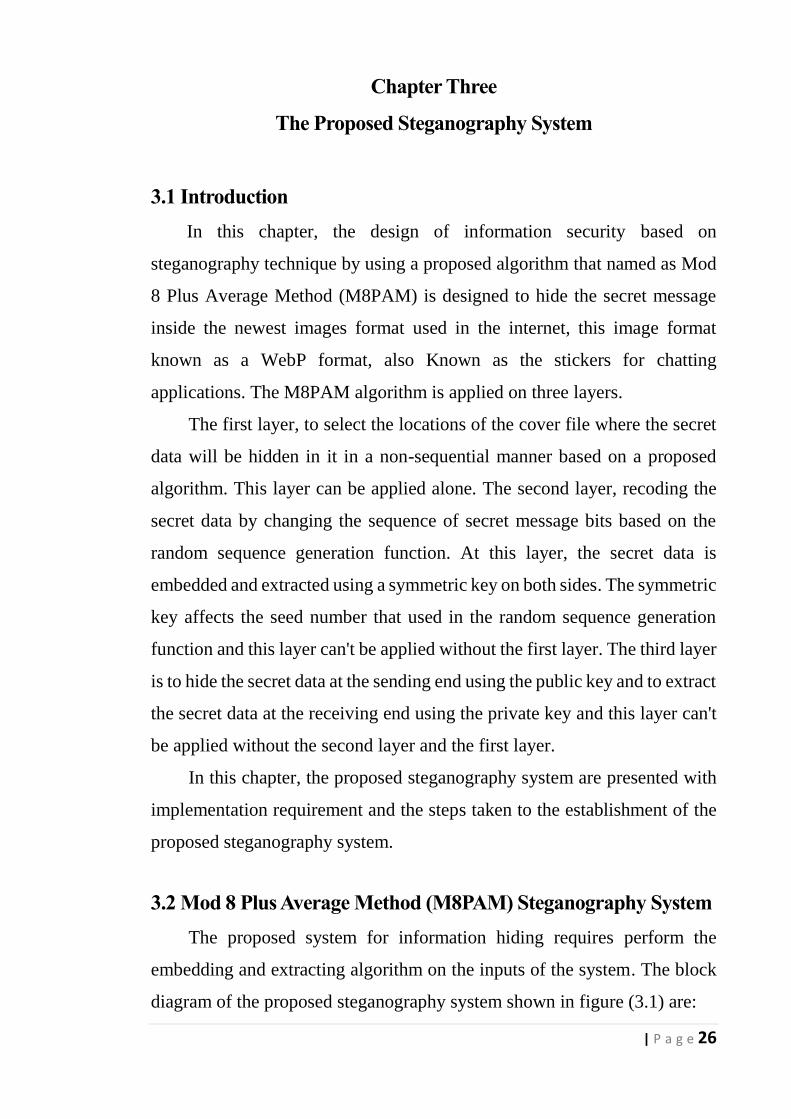
The proposed system for information hiding requires perform the
embedding and extracting algorithm on the inputs of the system. The block
diagram of the proposed steganography system shown in figure (3.1) are:
Chapter Three --------------------------------------------------------- The Proposed Steganography System
27 | P a g e
1) The proposed algorithm (M8PAM) works in a bi-direction way, first:
the process of data embedding. Second: the process of data extraction.
2) The secret data that needed to be protect from falling into the hands of
the intruders.
3) The cover file, which will carry the secret data, it should be unaffected
by the embedding process, as well as must keep its accuracy.
4) The optional key for increasing the security of the steganography
system, this key maybe represented by symmetric key or maybe
represented by the public-private key.
5) The stego file that represents the resultant of embedding process.
The secret data, cover file and optional key, if its exist, considered as
the inputs for the process of data embedding. The stego file and optional key
if it exist in the process of data embedding considered as the inputs for the
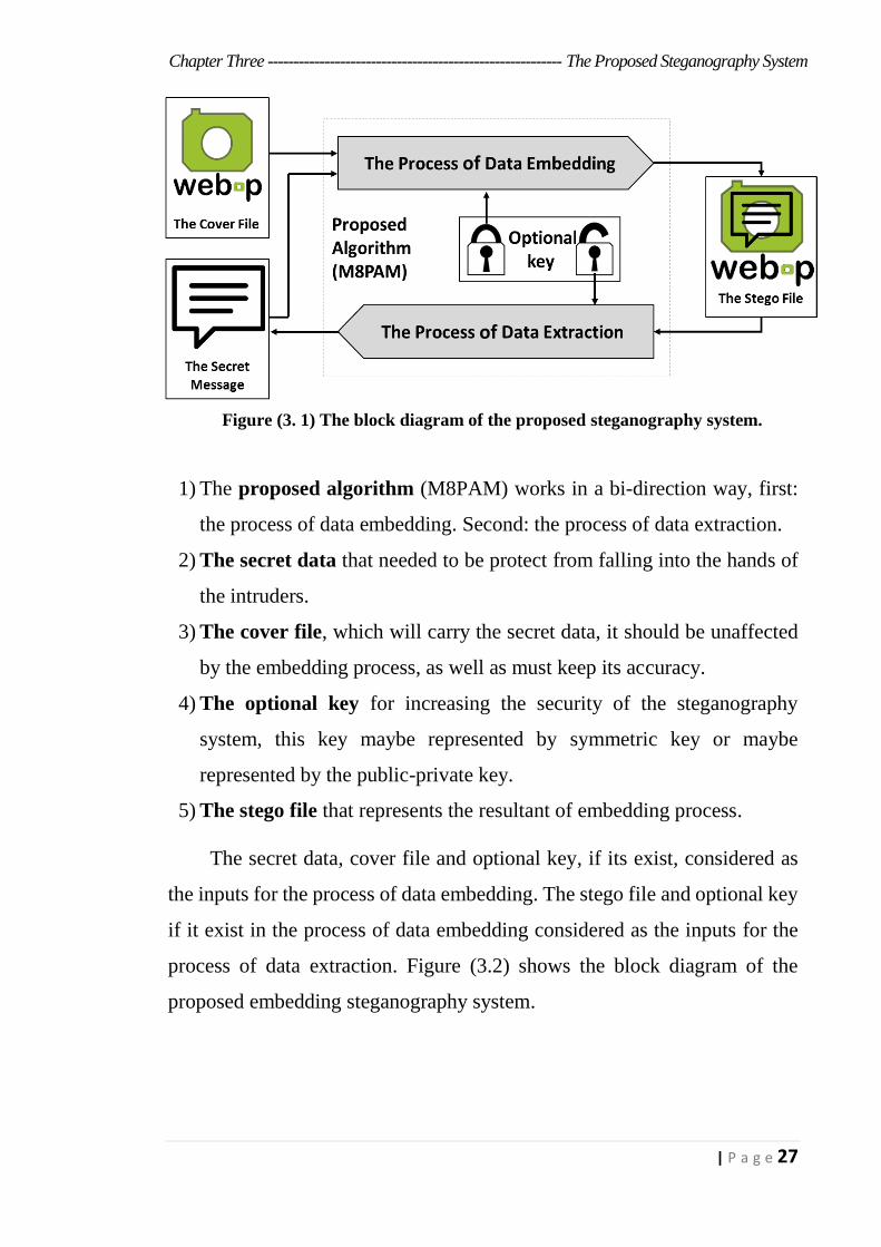
process of data extraction. Figure (3.2) shows the block diagram of the
proposed embedding steganography system.
Figure (3. 1) The block diagram of the proposed steganography system.
of
of
Chapter Three --------------------------------------------------------- The Proposed Steganography System
28 | P a g e
Figure (3. 2) Block diagram of the proposed embedding steganography system.
Store locations of blue band of
non-transparent pixels in array of
locations. Algorithm (3.4)
Convert secret
message to 3-
Bit digits.
Algorithm (3.3)
Apply Selection locations
algorithm to get the non-
sequential index. Algorithm (3.5)
Perform Embedding Algorithm (M8PAM)
Algorithm (3.1)
Redistributed process for
Encrypt 3-Bit digits of the
secret message. Figure (3.10)
Store locations of blue band of
non-transparent pixels in array of
locations. Algorithm (3.4)
Convert secret
message to 3-
Bit digits.
Algorithm (3.3)
Apply Selection locations
algorithm to get the non-
sequential index. Algorithm (3.5)
Perform Embedding Algorithm (M8PAM)
Algorithm (3.1)
SK
Layer one Layer Two Layer Three
If Select Pure Steganograph
y
If Select Symmetric Key Steganography
If Select Public Key Steganography
The Proposed Embedding Steganography System Select on of bellow layers
SK - Symmetric Key PK - Public Key
Redistributed process for
Encrypt 3-Bit digits of the
secret message. Figure (3.10)
Store locations of blue band of
non-transparent pixels in array of
locations. Algorithm (3.4)
Convert secret
message to 3-
Bit digits.
Algorithm (3.3)
Apply Selection locations
algorithm to get the non-
sequential index. Algorithm (3.5)
Perform Embedding Algorithm (M8PAM)
Algorithm (3.1)
Apply Public Key Steganography
by using RSA Algorithm.
Figure (3.12)
PK
Chapter Three --------------------------------------------------------- The Proposed Steganography System
29 | P a g e
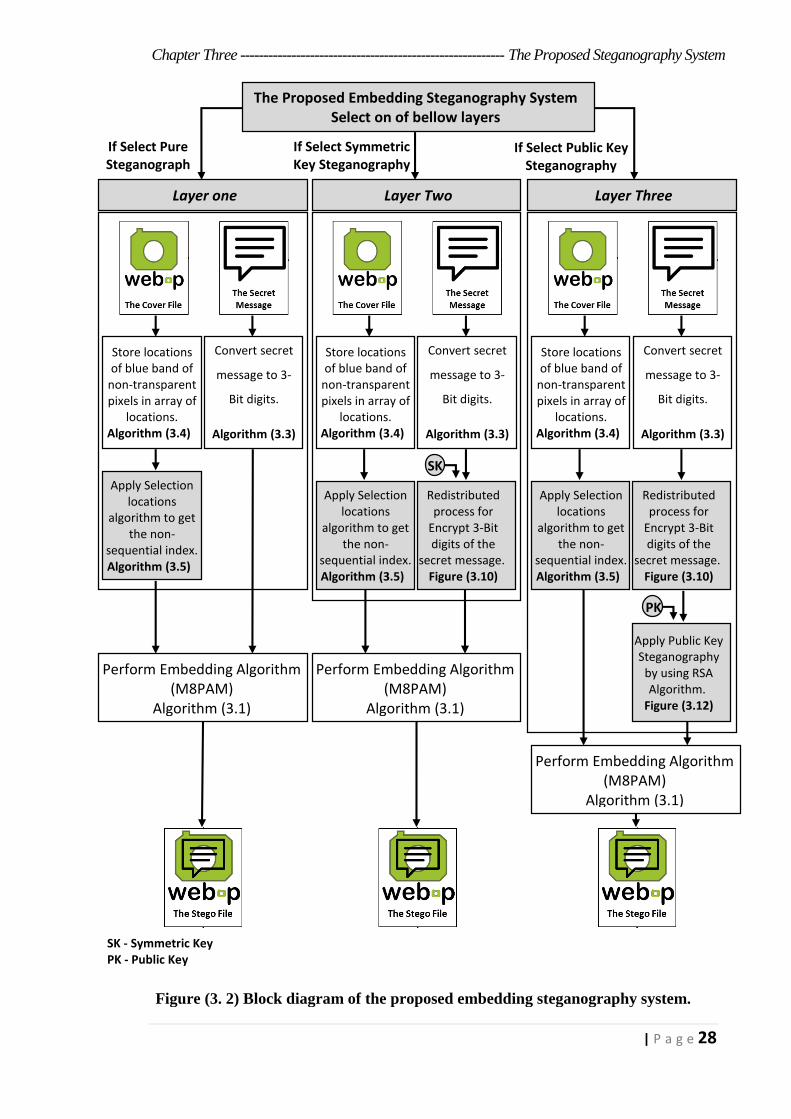
The processing portion, that relating to the proposed method (M8PAM)
in the figure (3.2) represent the proposed method for embedding the secret
data that designed in a way to hide every three bits of the secret message in
one sample of the cover file according to a proposed algorithm to select the
locations of the cover file which will carrying the bits of the secret message,
algorithm (3.1) shows the steps of the embedding process.
Algorithm (3.1) implementation of the embedding process.
Goal: embedding the secret message inside the cover file.
Input: The secret message as array of digits (ArrayM), the cover file as array of samples
(ArrayC).
Output: Stego File as array of samples (ArraySte).
Steps:
- Step1: Initialization the variables to repeat step 2 and 4, Let Loc = 0, Index= 0.
- Step2: For each digit in ArrayM And ArrayC Apply:
- Ocov = Cov= ArrayC[Loc]
- IF Cov Negative, Then Sign=-1 Else Sign=1
- Reminder = Cov Mod 8
- Cov = Cov – Reminder + ArrayM[Loc]
- Increment Central Change[Ocover -Cov]
- IF Sign = -1 Then Cov = Cov * -1
- Store the result
- Increment the index of location
- IF Loc equal Size of ArrayM Then go to step 4
Else repeat step 2
- Step3: Find the maximum value in Array of Central Change Then get it’s index
- Step4: For each digit in ArraySte Adding Central Change Value:
-ArraySte[Index] = ArraySte[Index] + Max
-Increment the index of location
-IF Index equal Size of ArraySte Then go to step5
Else repeat step4
- Step5: End
The value 8 came to allow the possibility of hiding three bits from the
secret message in every sample of the cover file, that's because the result of
2 power 3 equal 8, number 3 come to allow hiding three bits but not more.
On the other side the extraction process is applied, figure (3.3) shows the
Block diagram of the proposed extraction steganography system.
Chapter Three --------------------------------------------------------- The Proposed Steganography System
30 | P a g e
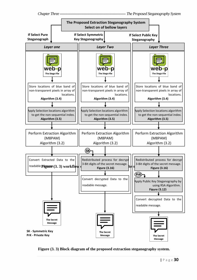
Figure (3. 3) workflow of the extraction process in the steganography system.
Layer one Layer Two Layer Three
If Select Pure Steganograph
y
If Select Symmetric Key Steganography
If Select Public Key Steganography
The Proposed Extraction Steganography System Select on of bellow layers
SK - Symmetric Key PrK - Private Key
Store locations of blue band of non-transparent pixels in array of
locations. Algorithm (3.4)
Convert Extracted Data to the
readable message.
Algorithm (3.6)
Apply Selection locations algorithm to get the non-sequential index.
Algorithm (3.5)
Perform Extraction Algorithm (M8PAM)
Algorithm (3.2)
SK
Redistributed process for decrypt 3-Bit digits of the secret message.
Figure (3.16)
Store locations of blue band of non-transparent pixels in array of
locations. Algorithm (3.4)
Convert decrypted Data to the
readable message.
Algorithm (3.6)
Apply Selection locations algorithm to get the non-sequential index.
Algorithm (3.5)
Perform Extraction Algorithm (M8PAM)
Algorithm (3.2)
Apply Public Key Steganography by using RSA Algorithm.
Figure (3.12)
PrK
Figure (3. 3) Block diagram of the proposed extraction steganography system.

Chapter Three --------------------------------------------------------- The Proposed Steganography System
31 | P a g e
The processing portion that related to the proposed method (M8PAM)
is shown in the figure (3.3), it represents the proposed method for extracting
the secret data that designed in a way to extract every three bits from one
sample of the cover file, based on remainder quotient resulting from dividing
the sample on 8, then subtract the value of the central change from the
remainder of division from the sample, after retrieval of all bits of the secret
data, it is converted to array of bytes then it translated into the formula of
secret data. Algorithm (3.2) shows the implementation of the extraction
process.
Algorithm (3.2) implementation of the extraction process.
Goal: extracting the secret message from the cover file.
Input: The Stego file as array of samples (ArraySte).
Output: The secret data as array of the digits (ArrayM).
Steps:
- Step1: Initialization the variables to repeat step 2, Let Loc = 0 and Index= 0.
- Step2: Get the Central Change from the embedded Hider.
- Step3: For each digit in ArraySte Apply:
- IF ArraySte[Loc] Negative
Then ArraySte[Loc] = ArraySte[Loc] * -1
- Reminder = ArraySte[Loc] Mod 8
- ArrayM[Loc]= Reminder - Central Change
- Increment the index of location
- IF Loc equal Size of Message Then go to step 4
Else repeat step 3
- Step4: End
3.3 The Embedding Process
In the previous section, the proposed method was described in details
that considered the kernel of the proposed information-hiding system. The
proposed system operates in two directions, the first applied at the sending
end, which performs the process of embedding the secret message inside the
cover file, the embedding processes are applied beside the three layers to
achieve the system aims. The second direction at the receiving end is
performing the extraction operations, to extract the secret message from the
Chapter Three --------------------------------------------------------- The Proposed Steganography System
32 | P a g e
cover file. The embedding process at least requires two parameters to
perform the hiding process. These main parameters are as follows:
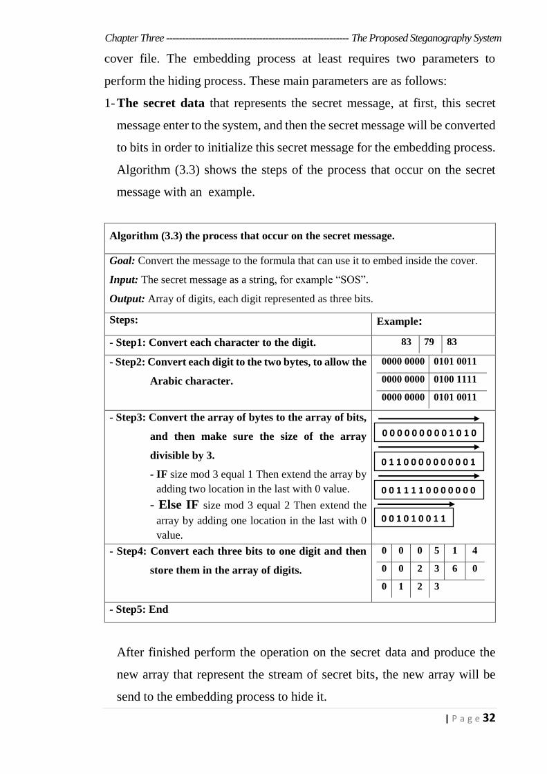
1- The secret data that represents the secret message, at first, this secret
message enter to the system, and then the secret message will be converted
to bits in order to initialize this secret message for the embedding process.
Algorithm (3.3) shows the steps of the process that occur on the secret
message with an example.
Algorithm (3.3) the process that occur on the secret message.
Goal: Convert the message to the formula that can use it to embed inside the cover.
Input: The secret message as a string, for example “SOS”.
Output: Array of digits, each digit represented as three bits.
Steps: Example:
- Step1: Convert each character to the digit. 83 79 83
- Step2: Convert each digit to the two bytes, to allow the
Arabic character.
0000 0000 00110101
0000 0000 0100 1111
0000 0000 00110101
- Step3: Convert the array of bytes to the array of bits,
and then make sure the size of the array
divisible by 3.
- IF size mod 3 equal 1 Then extend the array by
adding two location in the last with 0 value.
- Else IF size mod 3 equal 2 Then extend the
array by adding one location in the last with 0
value.
- Step4: Convert each three bits to one digit and then
store them in the array of digits.
0 0 0 5 1 4
0 0 2 3 6 0
0 1 2 3
- Step5: End
After finished perform the operation on the secret data and produce the
new array that represent the stream of secret bits, the new array will be
send to the embedding process to hide it.
0 0 0 0 0 0 0 0 0 1 0 1 0
0 1 1 0 0 0 0 0 0 0 0 0 1
0 0 1 1 1 1 0 0 0 0 0 0 0
0 0 1 0 1 0 0 1 1
Chapter Three --------------------------------------------------------- The Proposed Steganography System
33 | P a g e
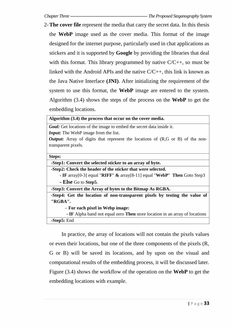
2- The cover file represent the media that carry the secret data. In this thesis
the WebP image used as the cover media. This format of the image
designed for the internet purpose, particularly used in chat applications as
stickers and it is supported by Google by providing the libraries that deal
with this format. This library programmed by native C/C++, so must be
linked with the Android APIs and the native C/C++, this link is known as
the Java Native Interface (JNI). After initializing the requirement of the
system to use this format, the WebP image are entered to the system.
Algorithm (3.4) shows the steps of the process on the WebP to get the
embedding locations.
Algorithm (3.4) the process that occur on the cover media.
Goal: Get locations of the image to embed the secret data inside it.
Input: The WebP image from the list.
Output: Array of digits that represent the locations of (R,G or B) of tha non-
transparent pixels.
Steps:
-Step1: Convert the selected sticker to an array of byte.
-Step2: Check the header of the sticker that were selected.
- IF array[0-3] equal "RIFF" & array[8-11] equal "WebP" Then Goto Step3
- Else Go to Step5.
-Step3: Convert the Array of bytes to the Bitmap As RGBA.
-Step4: Get the location of non-transparent pixels by testing the value of
"RGBA".
For each pixel in Webp image:
- IF Alpha band not equal zero Then store location in an array of locations
-Step5: End
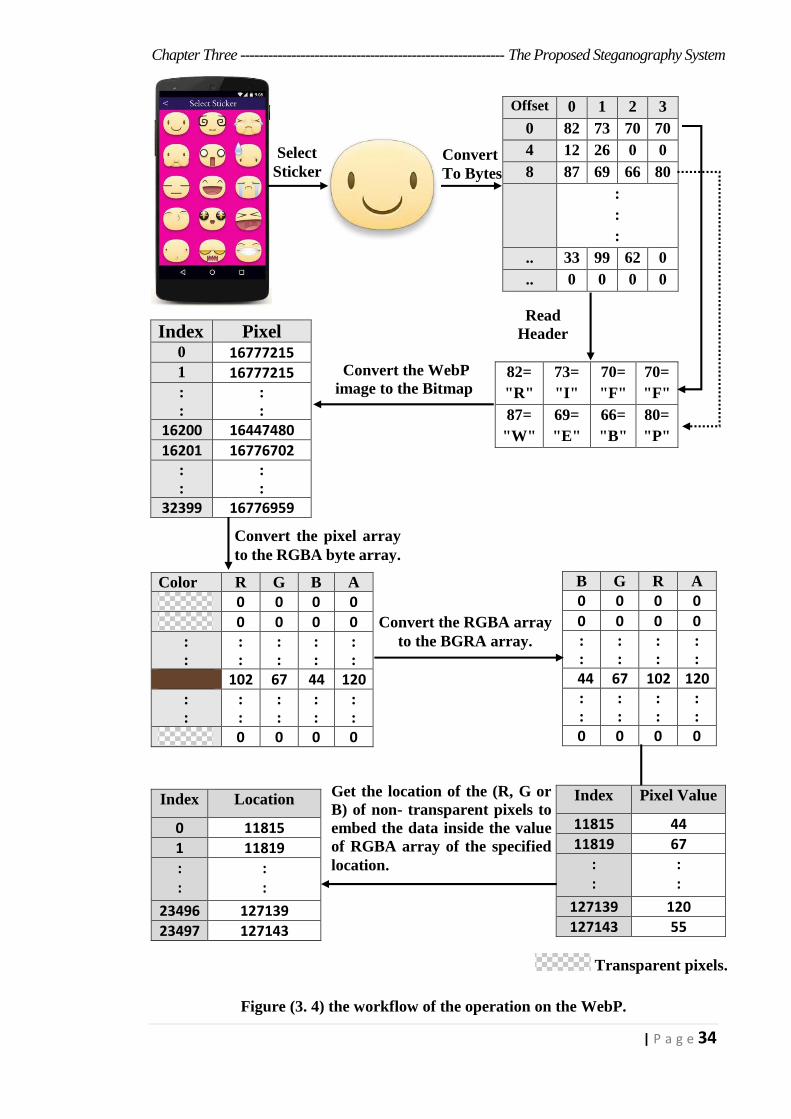
In practice, the array of locations will not contain the pixels values
or even their locations, but one of the three components of the pixels (R,
G or B) will be saved its locations, and by upon on the visual and
computational results of the embedding process, it will be discussed later.
Figure (3.4) shows the workflow of the operation on the WebP to get the
embedding locations with example.
Chapter Three --------------------------------------------------------- The Proposed Steganography System
34 | P a g e
Index Pixel 0 16777215
1 16777215 :
:
:
:
16200 16447480
16201 16776702 :
:
:
:
32399 16776959
Figure (3. 4) the workflow of the operation on the WebP.
Offset 0 1 2 3
0 82 73 70 70
4 12 26 0 0
8 87 69 66 80
:
:
:
.. 33 99 62 0
.. 0 0 0 0
82=
"R"
73=
"I"
70=
"F"
70=
"F"
87=
"W"
69=
"E"
66=
"B"
80=
"P"
Color R G B A
0 0 0 0
0 0 0 0
:
:
:
:
:
:
:
:
:
:
102 67 44 120
:
:
:
:
:
:
:
:
:
:
0 0 0 0
B G R A
0 0 0 0
0 0 0 0
:
:
:
:
:
:
:
:
44 67 102 120
:
:
:
:
:
:
:
:
0 0 0 0
Index Location
0 11815
1 11819
: :
: :
23496 127139
23497 127143
Select Sticker
Convert To Bytes
Read
Header
Convert the WebP
image to the Bitmap
Convert the pixel array
to the RGBA byte array.
Get the location of the (R, G or
B) of non- transparent pixels to
embed the data inside the value
of RGBA array of the specified
location.
Convert the RGBA array
to the BGRA array.
Index Pixel Value
11815 44
11819 67
: :
: :
127139 120
127143 55
Transparent pixels.
Chapter Three --------------------------------------------------------- The Proposed Steganography System
35 | P a g e
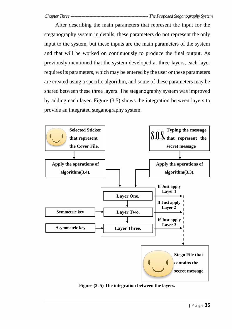
After describing the main parameters that represent the input for the
steganography system in details, these parameters do not represent the only
input to the system, but these inputs are the main parameters of the system
and that will be worked on continuously to produce the final output. As
previously mentioned that the system developed at three layers, each layer
requires its parameters, which may be entered by the user or these parameters
are created using a specific algorithm, and some of these parameters may be
shared between these three layers. The steganography system was improved
by adding each layer. Figure (3.5) shows the integration between layers to
provide an integrated steganography system.
Figure (3. 5) The integration between the layers.
S.O.S.
Apply the operations of
algorithm(3.4).
Layer One.
Layer Two.
Layer Three.
Apply the operations of
algorithm(3.3).
Selected Sticker
that represent
the Cover File.
Typing the message
that represent the
secret message
Stego File that
contains the
secret message.
Symmetric key
Asymmetric key
If Just apply
Layer 1
If Just apply
Layer 2
If Just apply
Layer 3
Chapter Three --------------------------------------------------------- The Proposed Steganography System
36 | P a g e
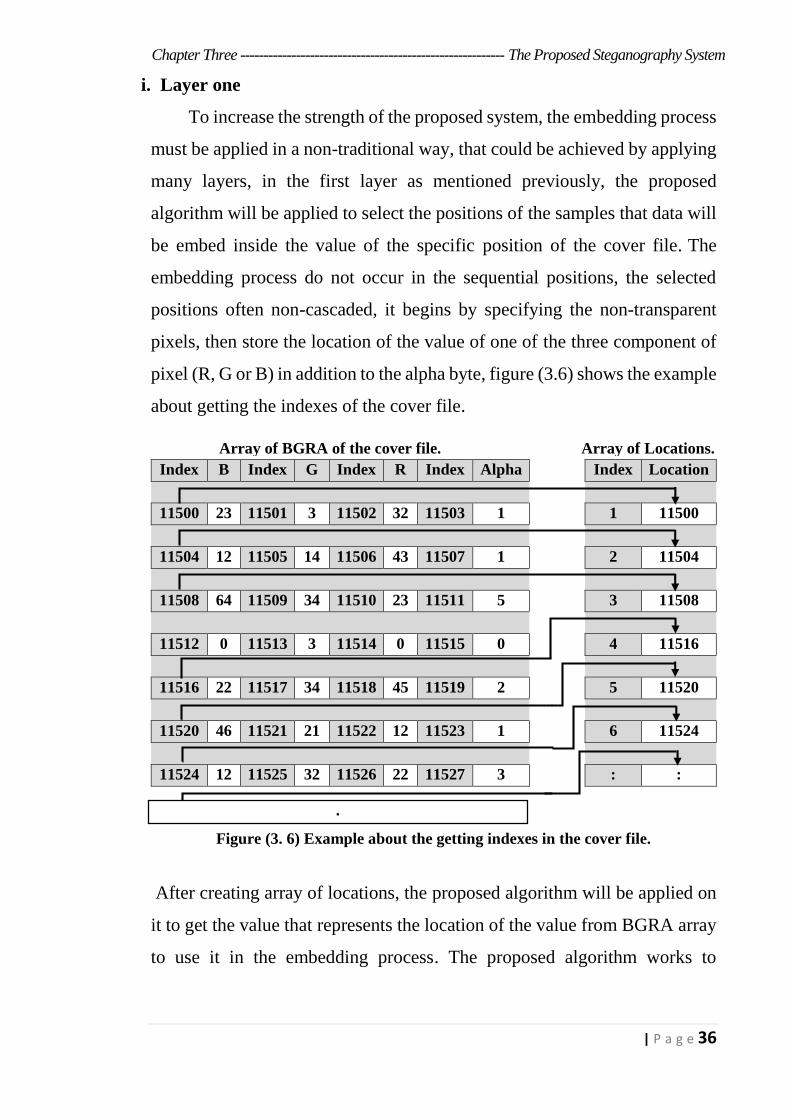
i. Layer one
To increase the strength of the proposed system, the embedding process
must be applied in a non-traditional way, that could be achieved by applying
many layers, in the first layer as mentioned previously, the proposed
algorithm will be applied to select the positions of the samples that data will
be embed inside the value of the specific position of the cover file. The
embedding process do not occur in the sequential positions, the selected
positions often non-cascaded, it begins by specifying the non-transparent
pixels, then store the location of the value of one of the three component of
pixel (R, G or B) in addition to the alpha byte, figure (3.6) shows the example
about getting the indexes of the cover file.
Index B Index G Index R Index Alpha
Index Location
11500 23 11501 3 11502 32 11503 1 1 11500
11504 12 11505 14 11506 43 11507 1 2 11504
11508 64 11509 34 11510 23 11511 5 3 11508
11512 0 11513 3 11514 0 11515 0 4 11516
11516 22 11517 34 11518 45 11519 2 5 11520
11520 46 11521 21 11522 12 11523 1 6 11524
11524 12 11525 32 11526 22 11527 3 : :
Figure (3. 6) Example about the getting indexes in the cover file.
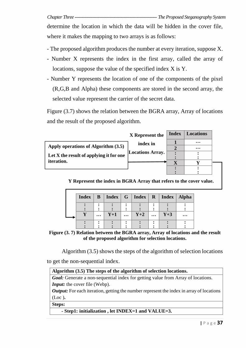
After creating array of locations, the proposed algorithm will be applied on
it to get the value that represents the location of the value from BGRA array
to use it in the embedding process. The proposed algorithm works to
:
Array of BGRA of the cover file. Array of Locations.
Chapter Three --------------------------------------------------------- The Proposed Steganography System
37 | P a g e
determine the location in which the data will be hidden in the cover file,
where it makes the mapping to two arrays is as follows:
- The proposed algorithm produces the number at every iteration, suppose X.
- Number X represents the index in the first array, called the array of
locations, suppose the value of the specified index X is Y.
- Number Y represents the location of one of the components of the pixel
(R,G,B and Alpha) these components are stored in the second array, the
selected value represent the carrier of the secret data.
Figure (3.7) shows the relation between the BGRA array, Array of locations
and the result of the proposed algorithm.
Figure (3. 7) Relation between the BGRA array, Array of locations and the result
of the proposed algorithm for selection locations.
Algorithm (3.5) shows the steps of the algorithm of selection locations
to get the non-sequential index.
Algorithm (3.5) The steps of the algorithm of selection locations.
Goal: Generate a non-sequential index for getting value from Array of locations.
Input: the cover file (Webp).
Output: For each iteration, getting the number represent the index in array of locations
(Loc ).
Steps:
- Step1: initialization , let INDEX=1 and VALUE=3.
Index Locations
1 …
2 …
: :
: :
X Y : :
: :
Index B Index G Index R Index Alpha
: :
: :
: :
: :
: :
: :
: :
: :
Y … Y+1 … Y+2 … Y+3 …
: :
: :
: :
: :
: :
: :
: :
: :
Apply operations of Algorithm (3.5)
Let X the result of applying it for one
iteration.
X Represent the
index in
Locations Array.
Y Represent the index in BGRA Array that refers to the cover value.
Chapter Three --------------------------------------------------------- The Proposed Steganography System
38 | P a g e
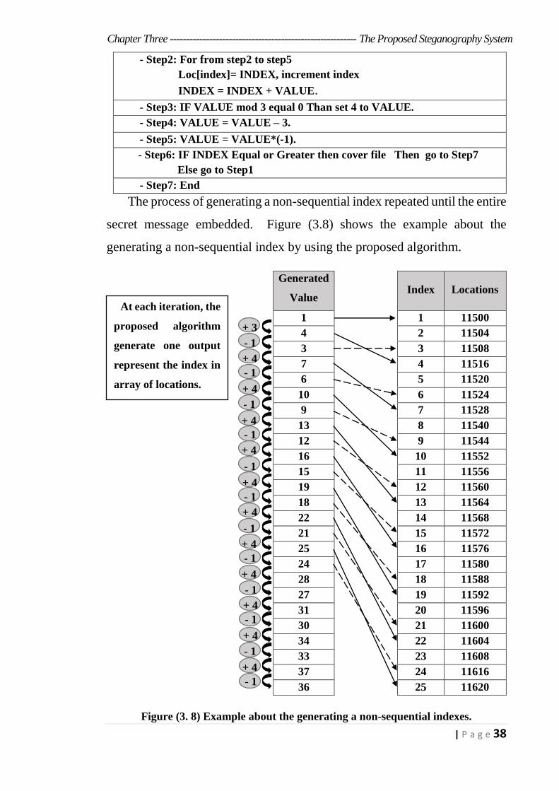
- Step2: For from step2 to step5
Loc[index]= INDEX, increment index
INDEX = INDEX + VALUE.
- Step3: IF VALUE mod 3 equal 0 Than set 4 to VALUE.
- Step4: VALUE = VALUE – 3.
- Step5: VALUE = VALUE*(-1).
- Step6: IF INDEX Equal or Greater then cover file Then go to Step7
Else go to Step1
- Step7: End
The process of generating a non-sequential index repeated until the entire
secret message embedded. Figure (3.8) shows the example about the
generating a non-sequential index by using the proposed algorithm.
Figure (3. 8) Example about the generating a non-sequential indexes.
Generated
Value
Index Locations
1 1 11500
4 2 11504
3 3 11508
7 4 11516
6 5 11520
10 6 11524
9 7 11528
13 8 11540
12 9 11544
16 10 11552
15 11 11556
19 12 11560
18 13 11564
22 14 11568
21 15 11572
25 16 11576
24 17 11580
28 18 11588
27 19 11592
31 20 11596
30 21 11600
34 22 11604
33 23 11608
37 24 11616
36 25 11620
At each iteration, the
proposed algorithm
generate one output
represent the index in
array of locations.
+ 3
- 1
+ 4
- 1
+ 4
- 1
+ 4
- 1
+ 4
- 1
+ 4
- 1
+ 4
- 1
+ 4
- 1
+ 4
- 1
+ 4
- 1
+ 4
- 1
+ 4
- 1
Chapter Three --------------------------------------------------------- The Proposed Steganography System
39 | P a g e
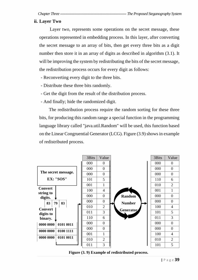
ii. Layer Two
Layer two, represents some operations on the secret message, these
operations represented in embedding process. In this layer, after converting
the secret message to an array of bits, then get every three bits as a digit
number then store it in an array of digits as described in algorithm (3.1). It
will be improving the system by redistributing the bits of the secret message,
the redistribution process occurs for every digit as follows:
- Reconverting every digit to the three bits.
- Distribute these three bits randomly.
- Get the digit from the result of the distribution process.
- And finally; hide the randomized digit.
The redistribution process require the random sorting for these three
bits, for producing this random range a special function in the programming
language library called "java.util.Random" will be used, this function based
on the Linear Congruential Generator (LCG). Figure (3.9) shows in example
of redistributed process.
Figure (3. 9) Example of redistributed process.
Value 3Bits Value 3Bits
0 000 0 000
0 000 0 000
0 000 0 000
6 110 5 101
2 010 1 001
1 001 4 100
0 000 0 000
0 000 0 000
4 100 2 010
5 101 3 011
3 011 6 110
0 000 0 000
0 000 0 000
4 100 1 001
2 010 2 010
5 101 3 011
The secret message.
EX: "SOS"
83 79 83
0000 0000 0101 0011
0000 0000 0100 1111
0000 0000 00110101
Convert
string to
digits.
Convert
digits to
binary.
Random
Number
Generator
Chapter Three --------------------------------------------------------- The Proposed Steganography System
40 | P a g e
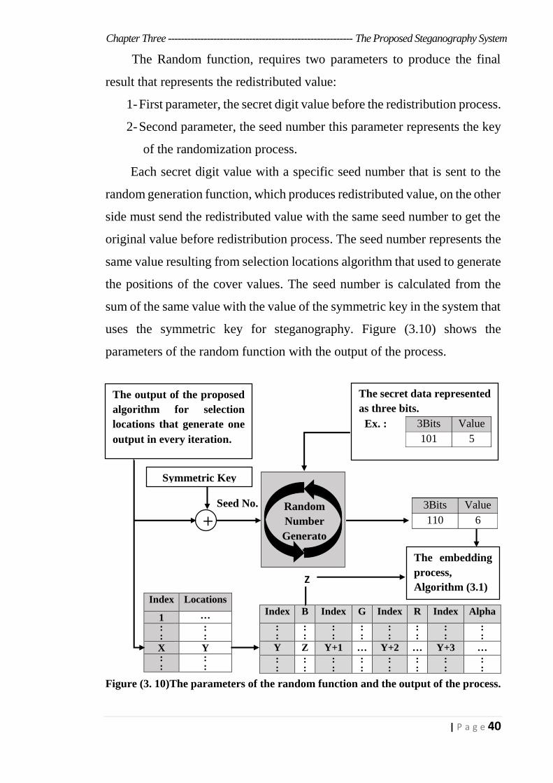
The Random function, requires two parameters to produce the final
result that represents the redistributed value:
1- First parameter, the secret digit value before the redistribution process.
2- Second parameter, the seed number this parameter represents the key
of the randomization process.
Each secret digit value with a specific seed number that is sent to the
random generation function, which produces redistributed value, on the other
side must send the redistributed value with the same seed number to get the
original value before redistribution process. The seed number represents the
same value resulting from selection locations algorithm that used to generate
the positions of the cover values. The seed number is calculated from the
sum of the same value with the value of the symmetric key in the system that
uses the symmetric key for steganography. Figure (3.10) shows the
parameters of the random function with the output of the process.
Figure (3. 10)The parameters of the random function and the output of the process.
Index B Index G Index R Index Alpha
: :
: :
: :
: :
: :
: :
: :
: :
Y Z Y+1 … Y+2 … Y+3 …
: :
: :
: :
: :
: :
: :
: :
: :
Index Locations
1 …
: :
: :
X Y : :
: :
The secret data represented
as three bits.
Value 3Bits Ex. :
5 101
The output of the proposed
algorithm for selection
locations that generate one
output in every iteration.
Random
Number
Generato
r
Symmetric Key
Value 3Bits
6 110
The embedding
process,
Algorithm (3.1) Z
+ Seed No.
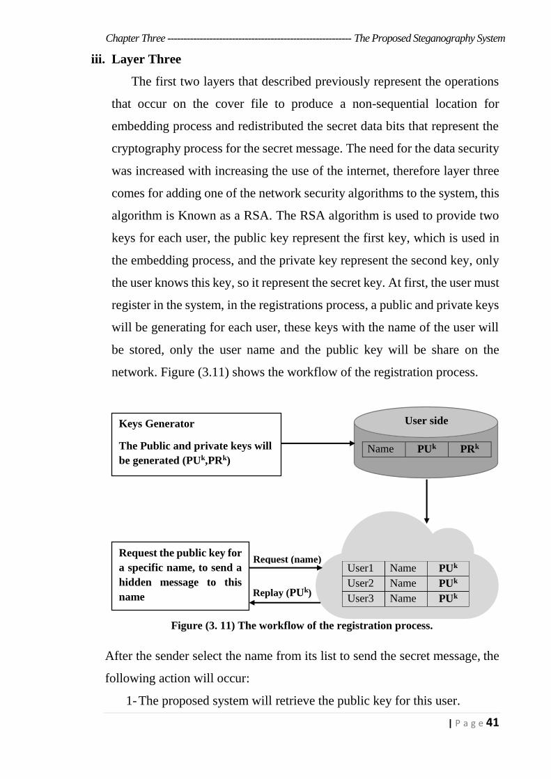
Chapter Three --------------------------------------------------------- The Proposed Steganography System
41 | P a g e
iii. Layer Three
The first two layers that described previously represent the operations
that occur on the cover file to produce a non-sequential location for
embedding process and redistributed the secret data bits that represent the
cryptography process for the secret message. The need for the data security
was increased with increasing the use of the internet, therefore layer three
comes for adding one of the network security algorithms to the system, this
algorithm is Known as a RSA. The RSA algorithm is used to provide two
keys for each user, the public key represent the first key, which is used in
the embedding process, and the private key represent the second key, only
the user knows this key, so it represent the secret key. At first, the user must
register in the system, in the registrations process, a public and private keys
will be generating for each user, these keys with the name of the user will
be stored, only the user name and the public key will be share on the
network. Figure (3.11) shows the workflow of the registration process.
Figure (3. 11) The workflow of the registration process.
After the sender select the name from its list to send the secret message, the
following action will occur:
1- The proposed system will retrieve the public key for this user.
PUk Name User1
PUk Name User2
PUk Name User3
Keys Generator
The Public and private keys will
be generated (PUk,PRk) PRk PUk Name
User side
Request the public key for
a specific name, to send a
hidden message to this
name
Request (name)
)kPUeplay (R
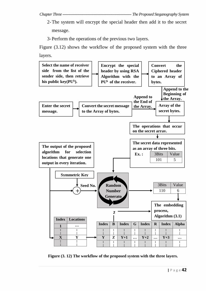
Chapter Three --------------------------------------------------------- The Proposed Steganography System
42 | P a g e
2- The system will encrypt the special header then add it to the secret
message.
3- Perform the operations of the previous two layers.
Figure (3.12) shows the workflow of the proposed system with the three
layers.
Figure (3. 12) The workflow of the proposed system with the three layers.
Index Locations
1 …
: :
: :
X Y : :
: :
Index B Index G Index R Index Alpha
: :
: :
: :
: :
: :
: :
: :
: :
Y Z Y+1 … Y+2 … Y+3 …
: :
: :
: :
: :
: :
: :
: :
: :
The output of the proposed
algorithm for selection
locations that generate one
output in every iteration.
The secret data represented
as an array of three bits.
Value 3Bits Ex. :
5 101
Random
Number
Generato
r
Symmetric Key
+ Value 3Bits
6 110
The embedding
process,
Algorithm (3.1)
Z
Select the name of receiver
side from the list of the
sender side, then retrieve
his public key(PUk).
Encrypt the special
header by using RSA
Algorithm with the
PUk of the receiver.
Enter the secret
message.
Convert the
Ciphered header
to an Array of
bytes.
Convert the secret message
to the Array of bytes.
The operations that occur
on the secret array.
Array of the
secret bytes.
Append to the
Beginning of
the Array.
Append to
the End of
the Array.
Seed No.
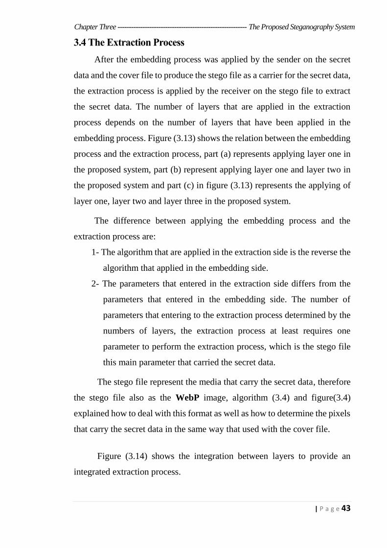
Chapter Three --------------------------------------------------------- The Proposed Steganography System
43 | P a g e
3.4 The Extraction Process
After the embedding process was applied by the sender on the secret
data and the cover file to produce the stego file as a carrier for the secret data,
the extraction process is applied by the receiver on the stego file to extract
the secret data. The number of layers that are applied in the extraction
process depends on the number of layers that have been applied in the
embedding process. Figure (3.13) shows the relation between the embedding
process and the extraction process, part (a) represents applying layer one in
the proposed system, part (b) represent applying layer one and layer two in
the proposed system and part (c) in figure (3.13) represents the applying of
layer one, layer two and layer three in the proposed system.
The difference between applying the embedding process and the
extraction process are:
1- The algorithm that are applied in the extraction side is the reverse the
algorithm that applied in the embedding side.
2- The parameters that entered in the extraction side differs from the
parameters that entered in the embedding side. The number of
parameters that entering to the extraction process determined by the
numbers of layers, the extraction process at least requires one
parameter to perform the extraction process, which is the stego file
this main parameter that carried the secret data.
The stego file represent the media that carry the secret data, therefore
the stego file also as the WebP image, algorithm (3.4) and figure(3.4)
explained how to deal with this format as well as how to determine the pixels
that carry the secret data in the same way that used with the cover file.
Figure (3.14) shows the integration between layers to provide an
integrated extraction process.
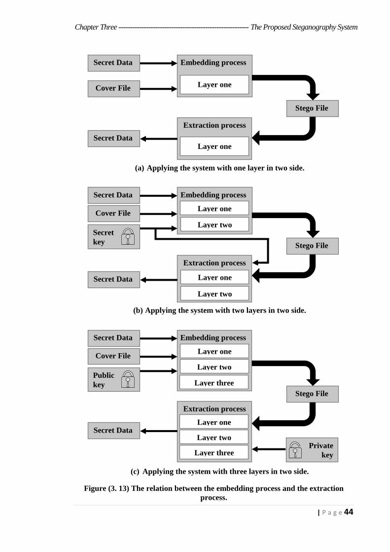
Chapter Three --------------------------------------------------------- The Proposed Steganography System
44 | P a g e
(a) Applying the system with one layer in two side.
(b) Applying the system with two layers in two side.
(c) Applying the system with three layers in two side.
Figure (3. 13) The relation between the embedding process and the extraction
process.
Secret Data
Cover File
Embedding process
Layer one
Extraction process
Layer one
Stego File
Secret Data
Secret Data
Cover File
Embedding process
Layer one
Extraction process
Stego File
Secret Data
Secret key
Layer two
Layer one
Layer two
Private key
Secret Data
Cover File
Embedding process
Layer one
Extraction process
Stego File
Secret Data
Public key
Layer two
Layer three
Layer one
Layer two
Layer three
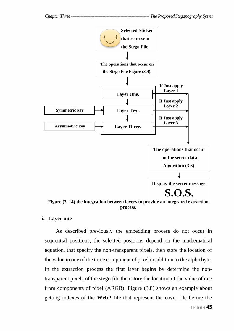
Chapter Three --------------------------------------------------------- The Proposed Steganography System
45 | P a g e
Figure (3. 14) the integration between layers to provide an integrated extraction
process.
i. Layer one
As described previously the embedding process do not occur in
sequential positions, the selected positions depend on the mathematical
equation, that specify the non-transparent pixels, then store the location of
the value in one of the three component of pixel in addition to the alpha byte.
In the extraction process the first layer begins by determine the non-
transparent pixels of the stego file then store the location of the value of one
from components of pixel (ARGB). Figure (3.8) shows an example about
getting indexes of the WebP file that represent the cover file before the
The operations that occur on
the Stego File Figure (3.4).
Layer One.
Layer Two.
Layer Three.
The operations that occur
on the secret data
Algorithm (3.6).
Selected Sticker
that represent
the Stego File.
Display the secret message.
S.O.S.
Symmetric key
Asymmetric key
If Just apply
Layer 1
If Just apply
Layer 2
If Just apply
Layer 3

Chapter Three --------------------------------------------------------- The Proposed Steganography System
46 | P a g e
embedding process and after the extraction process. After creating the array
of locations, the proposed algorithm used to generate the positions of this
locations that carry the secret data. Algorithm (3.5) and figure (3.7) shows
the work of proposed algorithm for selection locations. Figure (3.15) shows
the workflow of layer one in the extraction process.
Figure (3. 15) the workflow of layer one in the extraction process.
The extracted data represented as the digits, each one of them consists
of three bits, so some of the processes applied to retrieve and display the
secret message. Algorithm (3.6) shows the operations that occur on the
extracted secret data.
Each character represented as a two byte to allow the Arabic character
and the emoji in the secret message.
The operations that occur on
the Stego File, then getting
array of locations.
Appling the algorithm to
extract the embedded secret
data, Algorithm (3.2) shows
the extraction process in the
proposed Method (M8PAM).
Selected Sticker
that represent the
Stego File.
Display the secret message.
S.O.S.
Applying the proposed
algorithm to generating the
locations that content the
secret data. Algorithm (3.5)
shows the steps of this
proposed algorithm.
The operations that occur on
the secret Data. Algorithm (3.6).
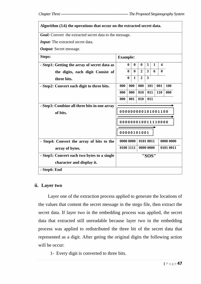
Chapter Three --------------------------------------------------------- The Proposed Steganography System
47 | P a g e
ii. Layer two
Layer one of the extraction process applied to generate the locations of
the values that content the secret message in the stego file, then extract the
secret data. If layer two in the embedding process was applied, the secret
data that extracted still unreadable because layer two in the embedding
process was applied to redistributed the three bit of the secret data that
represented as a digit. After geting the original digits the following action
will be occur:
1- Every digit is converted to three bits.
Algorithm (3.6) the operations that occur on the extracted secret data.
Goal: Convert the extracted secret data to the message.
Input: The extracted secret data.
Output: Secret message.
Steps: Example:
- Step1: Getting the array of secret data as
the digits, each digit Consist of
three bits.
0 0 0 5 1 4
0 0 2 3 6 0
0 1 2 3
- Step2: Convert each digit to three bits. 000 000 000 101 001 100
000 000 010 011 110 000
000 001 010 011
- Step3: Combine all three bits in one array
of bits.
- Step4: Convert the array of bits to the
array of bytes.
0000 0000 00110101 0000 0000
0100 1111 0000 0000 0101 0011
- Step5: Convert each two bytes to a single
character and display it.
"SOS"
- Step6: End
0 0 0 0 0 0 0 0 0 1 0 1 0 0 1 1 0 0
0 0 0 0 0 0 0 1 0 0 1 1 1 1 0 0 0 0
0 0 0 0 0 1 0 1 0 0 1
1
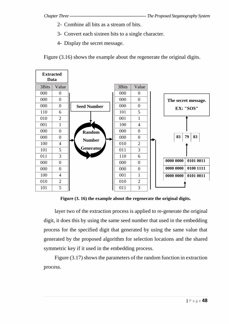
Chapter Three --------------------------------------------------------- The Proposed Steganography System
48 | P a g e
2- Combine all bits as a stream of bits.
3- Convert each sixteen bits to a single character.
4- Display the secret message.
Figure (3.16) shows the example about the regenerate the original digits.
Figure (3. 16) the example about the regenerate the original digits.
layer two of the extraction process is applied to re-generate the original
digit, it does this by using the same seed number that used in the embedding
process for the specified digit that generated by using the same value that
generated by the proposed algorithm for selection locations and the shared
symmetric key if it used in the embedding process.
Figure (3.17) shows the parameters of the random function in extraction
process.
Value 3Bits Value 3Bits
0 000 0 000
0 000 0 000
0 000 0 000
5 101 6 110
1 001 2 010
4 100 1 001
0 000 0 000
0 000 0 000
2 010 4 100
3 011 5 101
6 110 3 011
0 000 0 000
0 000 0 000
1 001 4 100
2 010 2 010
3 011 5 101
0000 0000 0101 0011
0000 0000 0100 1111
0000 0000 0101 0011
The secret message.
EX: "SOS"
83 79 83
Extracted
Data
Random
Number
Generator
Seed Number
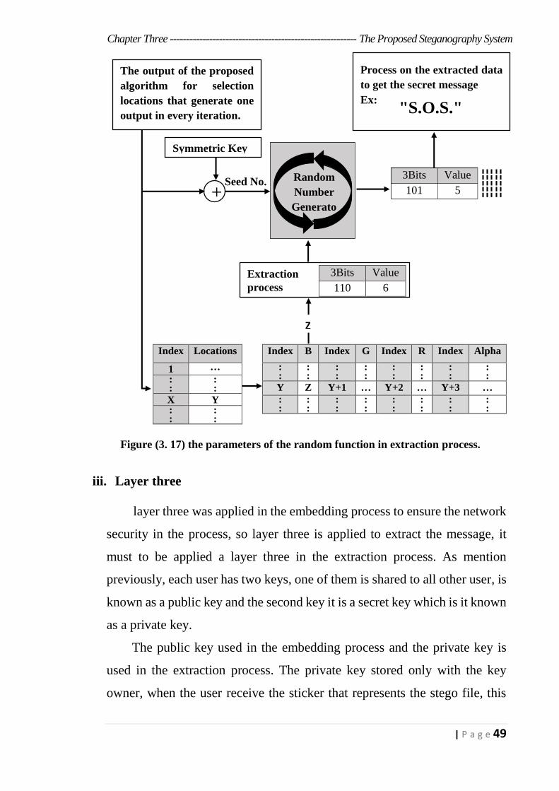
Chapter Three --------------------------------------------------------- The Proposed Steganography System
49 | P a g e
Figure (3. 17) the parameters of the random function in extraction process.
iii. Layer three
layer three was applied in the embedding process to ensure the network
security in the process, so layer three is applied to extract the message, it
must to be applied a layer three in the extraction process. As mention
previously, each user has two keys, one of them is shared to all other user, is
known as a public key and the second key it is a secret key which is it known
as a private key.
The public key used in the embedding process and the private key is
used in the extraction process. The private key stored only with the key
owner, when the user receive the sticker that represents the stego file, this
Index B Index G Index R Index Alpha
: :
: :
: :
: :
: :
: :
: :
: :
Y Z Y+1 … Y+2 … Y+3 …
: :
: :
: :
: :
: :
: :
: :
: :
Index Locations
1 …
: :
: :
X Y : :
: :
Process on the extracted data
to get the secret message
Ex:
The output of the proposed
algorithm for selection
locations that generate one
output in every iteration.
Random
Number
Generato
r
Symmetric Key
Value 3Bits
5 101
Extraction
process
Z
+
"S.O.S."
Seed No.
Value 3Bits
6 110
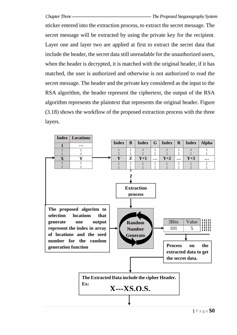
Chapter Three --------------------------------------------------------- The Proposed Steganography System
50 | P a g e
sticker entered into the extraction process, to extract the secret message. The
secret message will be extracted by using the private key for the recipient.
Layer one and layer two are applied at first to extract the secret data that
include the header, the secret data still unreadable for the unauthorized users,
when the header is decrypted, it is matched with the original header, if it has
matched, the user is authorized and otherwise is not authorized to read the
secret message. The header and the private key considered as the input to the
RSA algorithm, the header represent the ciphertext, the output of the RSA
algorithm represents the plaintext that represents the original header. Figure
(3.18) shows the workflow of the proposed extraction process with the three
layers.
Index B Index G Index R Index Alpha
: :
: :
: :
: :
: :
: :
: :
: :
Y Z Y+1 … Y+2 … Y+3 …
: :
: :
: :
: :
: :
: :
: :
: :
Index Locations
1 …
: :
: :
X Y : :
: :
Process on the
extracted data to get
the secret data.
The proposed algoritm to
selection locations that
generate one output
represent the index in array
of locations and the seed
number for the random
generation function
Random
Number
Generato
r
Extraction
process
Z
Value 3Bits
5 101
The Extracted Data include the cipher Header.
Ex:
X---XS.O.S.
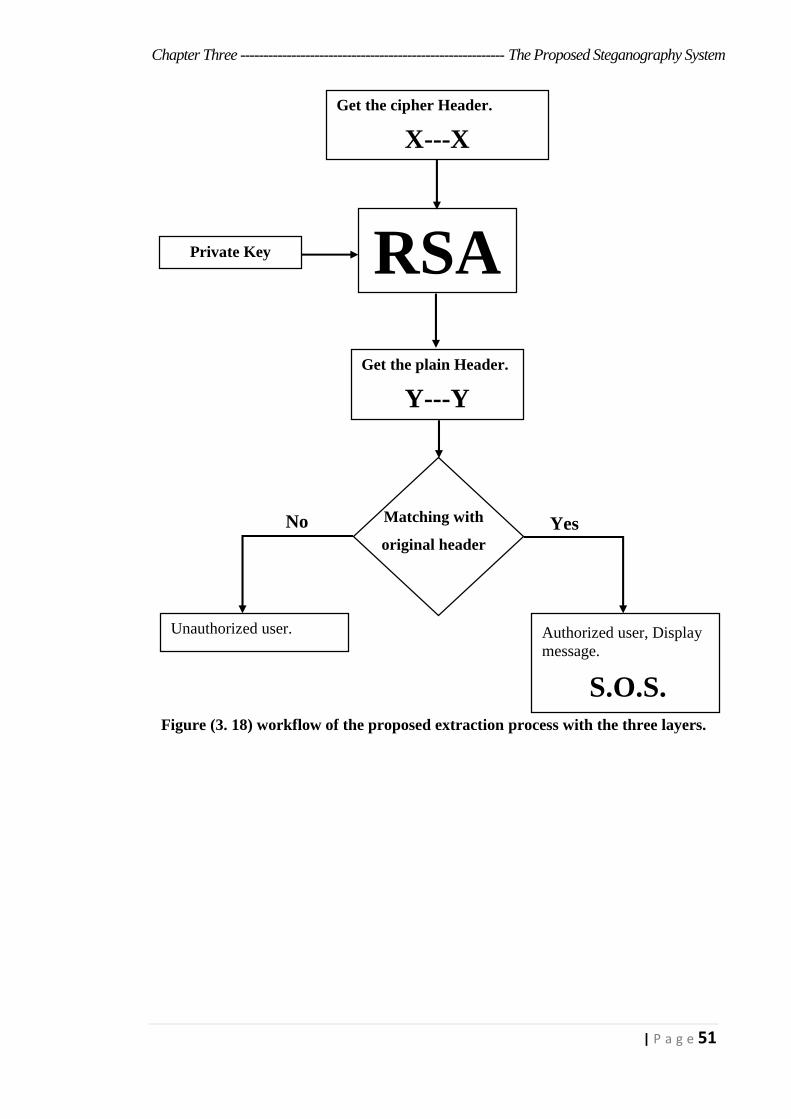
Chapter Three --------------------------------------------------------- The Proposed Steganography System
51 | P a g e
Figure (3. 18) workflow of the proposed extraction process with the three layers.
S.O.S.
Get the cipher Header.
X---X
RSA Private Key
Get the plain Header.
Y---Y
Authorized user, Display
message.
Unauthorized user.
No Yes Matching with
original header
Chapter Four
User Interfaces and
Experimental Results
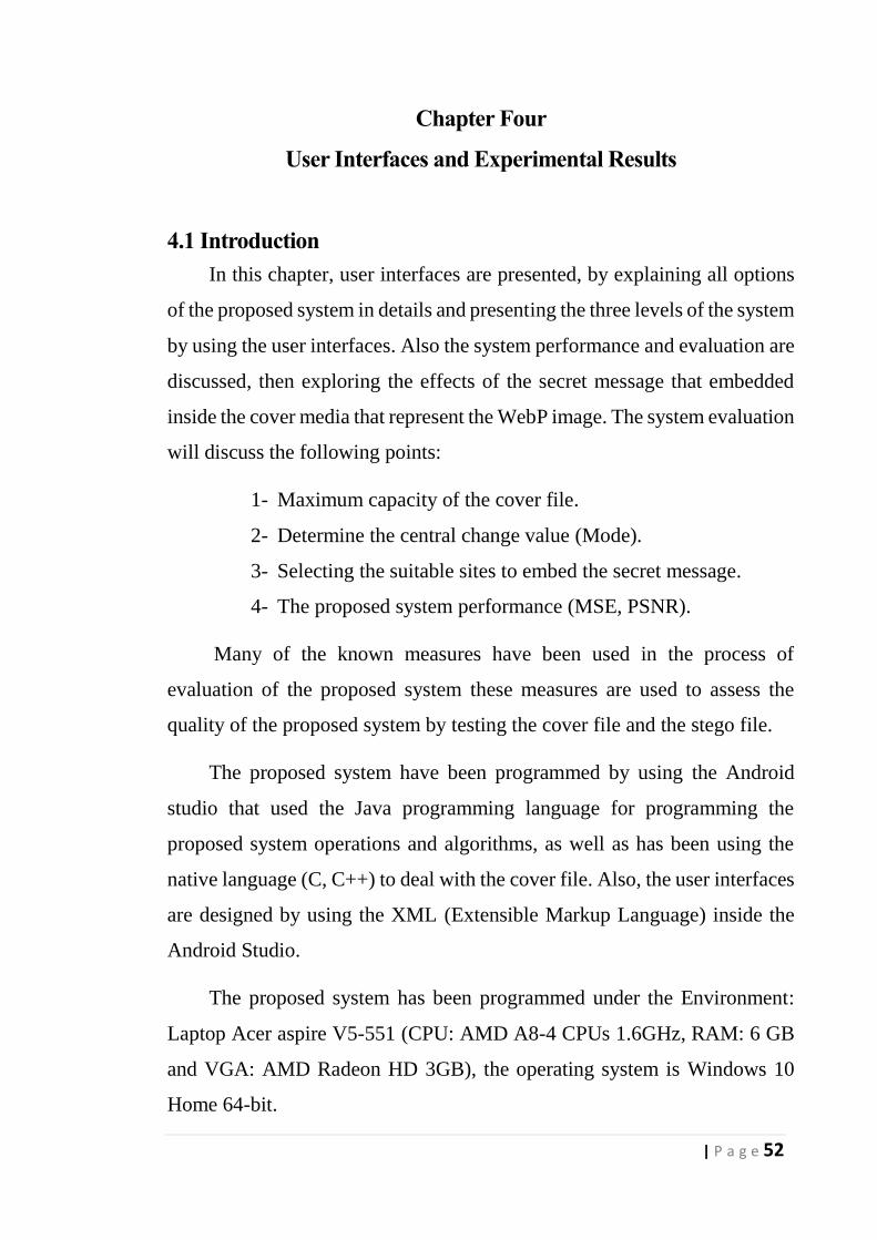
Chapter Four --------------------------------------------------- User Interfaces and Experimental Results
52 | P a g e
Chapter Four
User Interfaces and Experimental Results
4.1 Introduction
In this chapter, user interfaces are presented, by explaining all options
of the proposed system in details and presenting the three levels of the system
by using the user interfaces. Also the system performance and evaluation are
discussed, then exploring the effects of the secret message that embedded
inside the cover media that represent the WebP image. The system evaluation
will discuss the following points:
1- Maximum capacity of the cover file.
2- Determine the central change value (Mode).
3- Selecting the suitable sites to embed the secret message.
4- The proposed system performance (MSE, PSNR).
Many of the known measures have been used in the process of
evaluation of the proposed system these measures are used to assess the
quality of the proposed system by testing the cover file and the stego file.
The proposed system have been programmed by using the Android
studio that used the Java programming language for programming the
proposed system operations and algorithms, as well as has been using the
native language (C, C++) to deal with the cover file. Also, the user interfaces
are designed by using the XML (Extensible Markup Language) inside the
Android Studio.
The proposed system has been programmed under the Environment:
Laptop Acer aspire V5-551 (CPU: AMD A8-4 CPUs 1.6GHz, RAM: 6 GB
and VGA: AMD Radeon HD 3GB), the operating system is Windows 10
Home 64-bit.
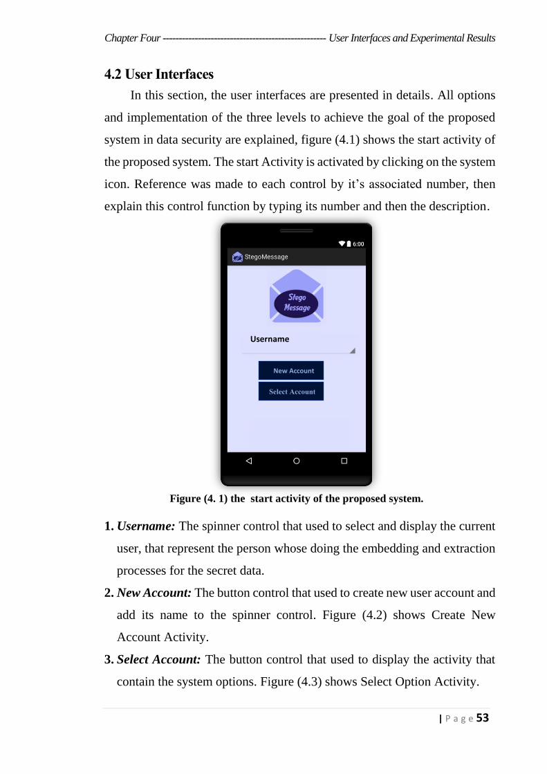
Chapter Four --------------------------------------------------- User Interfaces and Experimental Results
53 | P a g e
4.2 User Interfaces
In this section, the user interfaces are presented in details. All options
and implementation of the three levels to achieve the goal of the proposed
system in data security are explained, figure (4.1) shows the start activity of
the proposed system. The start Activity is activated by clicking on the system
icon. Reference was made to each control by it’s associated number, then
explain this control function by typing its number and then the description.
1. Username: The spinner control that used to select and display the current
user, that represent the person whose doing the embedding and extraction
processes for the secret data.
2. New Account: The button control that used to create new user account and
add its name to the spinner control. Figure (4.2) shows Create New
Account Activity.
3. Select Account: The button control that used to display the activity that
contain the system options. Figure (4.3) shows Select Option Activity.
Figure (4. 1) the start activity of the proposed system.
New Account
Select Account
Username
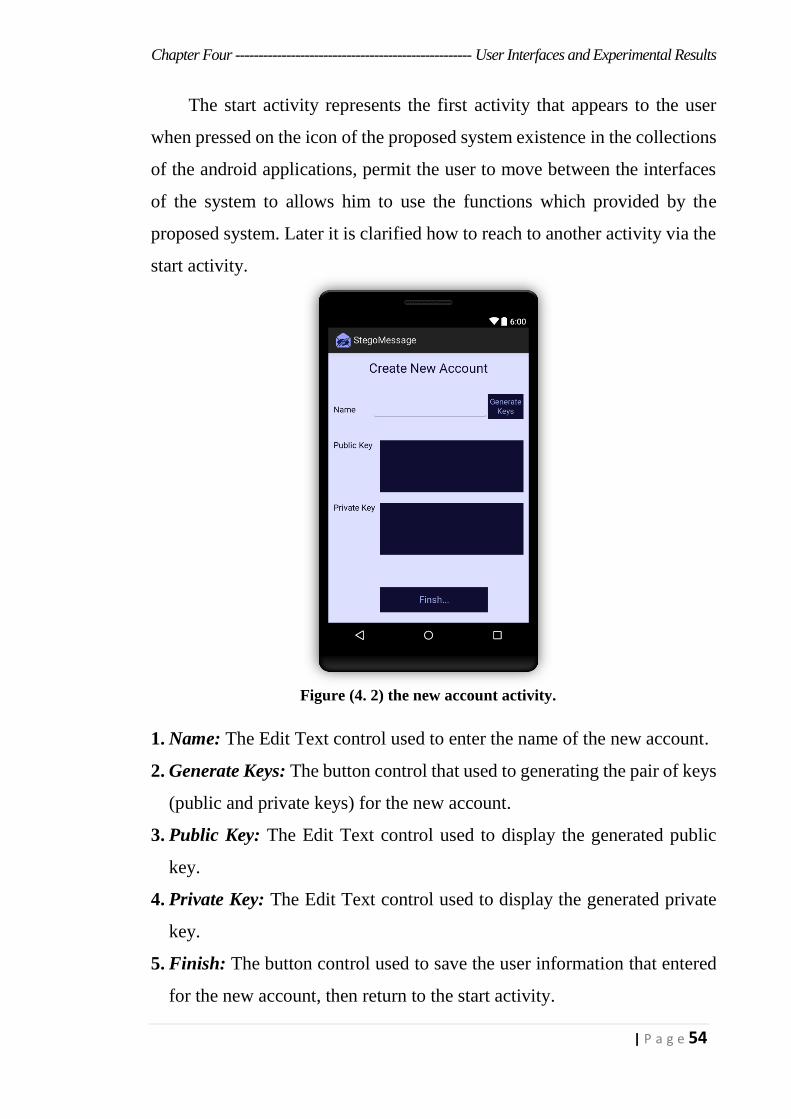
Chapter Four --------------------------------------------------- User Interfaces and Experimental Results
54 | P a g e
The start activity represents the first activity that appears to the user
when pressed on the icon of the proposed system existence in the collections
of the android applications, permit the user to move between the interfaces
of the system to allows him to use the functions which provided by the
proposed system. Later it is clarified how to reach to another activity via the
start activity.
1. Name: The Edit Text control used to enter the name of the new account.
2. Generate Keys: The button control that used to generating the pair of keys
(public and private keys) for the new account.
3. Public Key: The Edit Text control used to display the generated public
key.
4. Private Key: The Edit Text control used to display the generated private
key.
5. Finish: The button control used to save the user information that entered
for the new account, then return to the start activity.
Figure (4. 2) the new account activity.
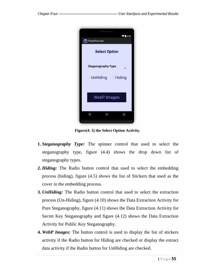
Chapter Four --------------------------------------------------- User Interfaces and Experimental Results
55 | P a g e
1. Steganography Type: The spinner control that used to select the
steganography type, figure (4.4) shows the drop down list of
steganography types.
2. Hiding: The Radio button control that used to select the embedding
process (hiding), figure (4.5) shows the list of Stickers that used as the
cover in the embedding process.
3. UnHiding: The Radio button control that used to select the extraction
process (Un-Hiding), figure (4.10) shows the Data Extraction Activity for
Pure Steganography, figure (4.11) shows the Data Extraction Activity for
Secret Key Steganography and figure (4.12) shows the Data Extraction
Activity for Public Key Steganography.
4. WebP Images: The button control is used to display the list of stickers
activity if the Radio button for Hiding are checked or display the extract
data activity if the Radio button for UnHiding are checked.
Figure(4. 3) the Select Option Activity.
Steganography Type

Chapter Four --------------------------------------------------- User Interfaces and Experimental Results
56 | P a g e
Pressing on the button control that named as WebP Images in the
figure (4.3) and the Radio button control that called hiding is selected. The
activity that contains list of stickers that represent the cover media is
displayed figure (4. 5). After the stickers activity is displayed, the user can
select one of the sticker to embed the secret message inside it, after the sticker
are selected, one of three activities will be displayed to embedding process
with one of three steganography types that shows in figure (4. 4):
a. Pure Steganography: Select this type to embed or extract the data
without any sharing prior information, this type applied for level one and
level two from the proposed system. Figure (4.6) shows the Embedding
process activity by using the Pure Steganography.
b. Secret key Steganography: Select this type to embedding or extracting
data with sharing prior information that represent the secret key, which is
added to the output of the proposed algorithm for selection location as the
Figure(4. 5) the list of Stickers. Figure (4. 4) the steganography types.
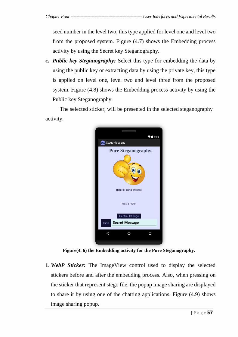
Chapter Four --------------------------------------------------- User Interfaces and Experimental Results
57 | P a g e
seed number in the level two, this type applied for level one and level two
from the proposed system. Figure (4.7) shows the Embedding process
activity by using the Secret key Steganography.
c. Public key Steganography: Select this type for embedding the data by
using the public key or extracting data by using the private key, this type
is applied on level one, level two and level three from the proposed
system. Figure (4.8) shows the Embedding process activity by using the
Public key Steganography.
The selected sticker, will be presented in the selected steganography
activity.
1. WebP Sticker: The ImageView control used to display the selected
stickers before and after the embedding process. Also, when pressing on
the sticker that represent stego file, the popup image sharing are displayed
to share it by using one of the chatting applications. Figure (4.9) shows
image sharing popup.
Figure(4. 6) the Embedding activity for the Pure Steganography.
Secret Message
Pure Steganography.

Chapter Four --------------------------------------------------- User Interfaces and Experimental Results
58 | P a g e
2. Before Hiding Process: The TextView control used to notify the user
about sticker before and after the embedding process.
3. MSE & PSNR: The TextView control used to display the amount of the
MSE and PSNR for the embedding process.
4. Secret Message: The Edit Text control used to enter the secret message.
5. Hide: The button control used to perform the hiding process.
In Figure(4. 7) the controls used to perform the following tasks:
1. Secret Key: The Edit Text control used to enter the secret key, the secret
key must be shared between the embedding side and the extraction side.
2. Secret Message: The Edit Text control used to enter the secret message.
3. Hide Text With L2: The button control used to perform the hiding process.
4. Before: The ImageView control used to display the selected stickers
before the embedding process.
Figure(4. 8) the Embedding activity
for the Public key Steganography.
Figure(4. 7) the Embedding activity for
the Secret key Steganography.
Secret Message
Secret Message
Secret key Steganography. Public key Steganography.
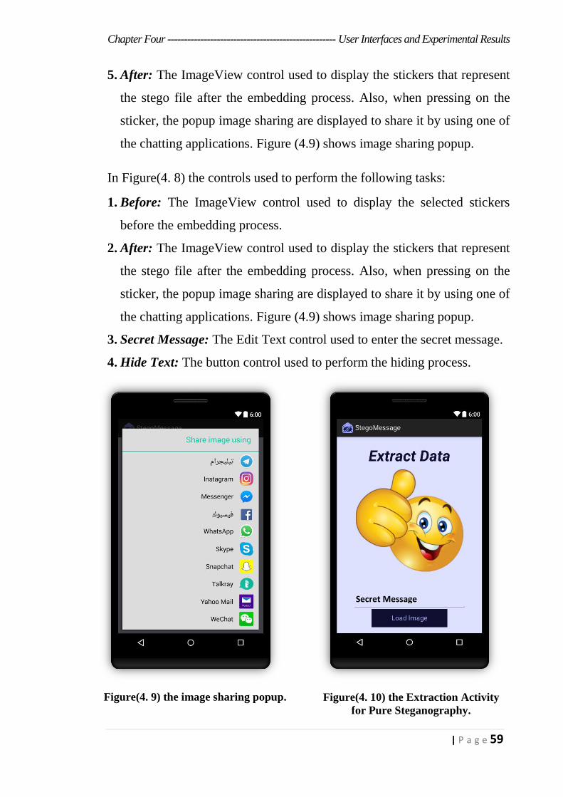
Chapter Four --------------------------------------------------- User Interfaces and Experimental Results
59 | P a g e
5. After: The ImageView control used to display the stickers that represent
the stego file after the embedding process. Also, when pressing on the
sticker, the popup image sharing are displayed to share it by using one of
the chatting applications. Figure (4.9) shows image sharing popup.
In Figure(4. 8) the controls used to perform the following tasks:
1. Before: The ImageView control used to display the selected stickers
before the embedding process.
2. After: The ImageView control used to display the stickers that represent
the stego file after the embedding process. Also, when pressing on the
sticker, the popup image sharing are displayed to share it by using one of
the chatting applications. Figure (4.9) shows image sharing popup.
3. Secret Message: The Edit Text control used to enter the secret message.
4. Hide Text: The button control used to perform the hiding process.
Figure(4. 9) the image sharing popup. Figure(4. 10) the Extraction Activity
for Pure Steganography.
Secret Message
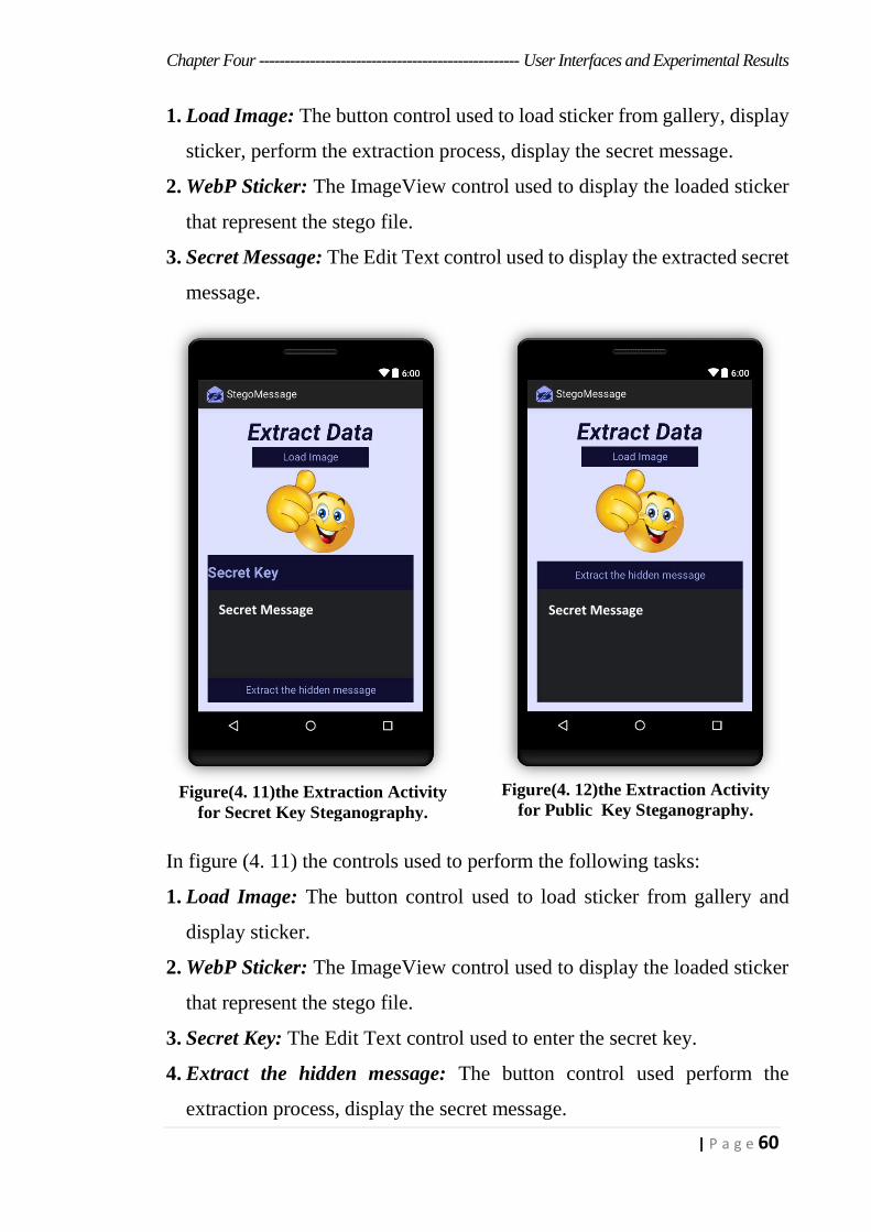
Chapter Four --------------------------------------------------- User Interfaces and Experimental Results
60 | P a g e
1. Load Image: The button control used to load sticker from gallery, display
sticker, perform the extraction process, display the secret message.
2. WebP Sticker: The ImageView control used to display the loaded sticker
that represent the stego file.
3. Secret Message: The Edit Text control used to display the extracted secret
message.
In figure (4. 11) the controls used to perform the following tasks:
1. Load Image: The button control used to load sticker from gallery and
display sticker.
2. WebP Sticker: The ImageView control used to display the loaded sticker
that represent the stego file.
3. Secret Key: The Edit Text control used to enter the secret key.
4. Extract the hidden message: The button control used perform the
extraction process, display the secret message.
Figure(4. 11)the Extraction Activity
for Secret Key Steganography.
Figure(4. 12)the Extraction Activity
for Public Key Steganography.
Secret Message Secret Message
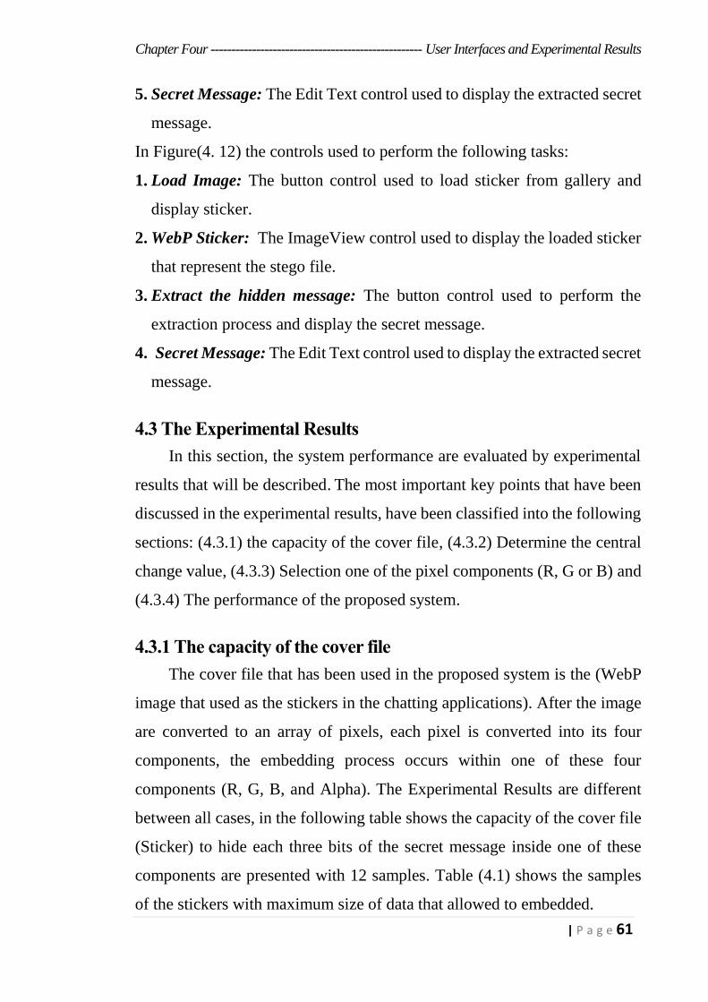
Chapter Four --------------------------------------------------- User Interfaces and Experimental Results
61 | P a g e
5. Secret Message: The Edit Text control used to display the extracted secret
message.
In Figure(4. 12) the controls used to perform the following tasks:
1. Load Image: The button control used to load sticker from gallery and
display sticker.
2. WebP Sticker: The ImageView control used to display the loaded sticker
that represent the stego file.
3. Extract the hidden message: The button control used to perform the
extraction process and display the secret message.
4. Secret Message: The Edit Text control used to display the extracted secret
message.
4.3 The Experimental Results
In this section, the system performance are evaluated by experimental
results that will be described. The most important key points that have been
discussed in the experimental results, have been classified into the following
sections: (4.3.1) the capacity of the cover file, (4.3.2) Determine the central
change value, (4.3.3) Selection one of the pixel components (R, G or B) and
(4.3.4) The performance of the proposed system.
4.3.1 The capacity of the cover file
The cover file that has been used in the proposed system is the (WebP
image that used as the stickers in the chatting applications). After the image
are converted to an array of pixels, each pixel is converted into its four
components, the embedding process occurs within one of these four
components (R, G, B, and Alpha). The Experimental Results are different
between all cases, in the following table shows the capacity of the cover file
(Sticker) to hide each three bits of the secret message inside one of these
components are presented with 12 samples. Table (4.1) shows the samples
of the stickers with maximum size of data that allowed to embedded.
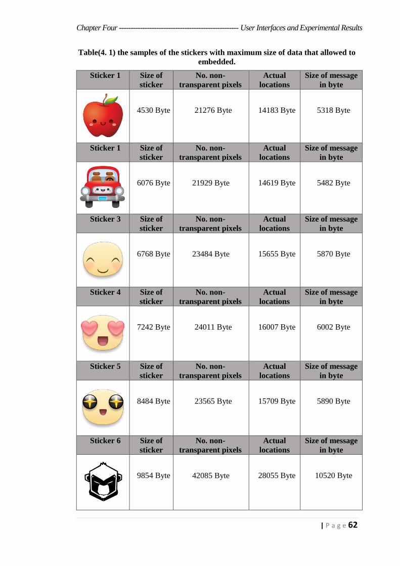
Chapter Four --------------------------------------------------- User Interfaces and Experimental Results
62 | P a g e
Table(4. 1) the samples of the stickers with maximum size of data that allowed to
embedded. Sticker 1 Size of
sticker
No. non-
transparent pixels
Actual
locations
Size of message
in byte
4530 Byte 21276 Byte 14183 Byte 5318 Byte
Sticker 1 Size of
sticker
No. non-
transparent pixels
Actual
locations
Size of message
in byte
6076 Byte 21929 Byte 14619 Byte 5482 Byte
Sticker 3 Size of
sticker
No. non-
transparent pixels
Actual
locations
Size of message
in byte
6768 Byte 23484 Byte 15655 Byte 5870 Byte
Sticker 4 Size of
sticker
No. non-
transparent pixels
Actual
locations
Size of message
in byte
7242 Byte 24011 Byte 16007 Byte 6002 Byte
Sticker 5 Size of
sticker
No. non-
transparent pixels
Actual
locations
Size of message
in byte
8484 Byte 23565 Byte 15709 Byte 5890 Byte
Sticker 6 Size of
sticker
No. non-
transparent pixels
Actual
locations
Size of message
in byte
9854 Byte 42085 Byte 28055 Byte 10520 Byte

Chapter Four --------------------------------------------------- User Interfaces and Experimental Results
63 | P a g e
Sticker 7 Size of
sticker
No. non-
transparent pixels
Actual
locations
Size of message
in byte
12994 Byte 20742 Byte 13827 Byte 5185 Byte
Sticker 8 Size of
sticker
No. non-
transparent pixels
Actual
locations
Size of message
in byte
25948 Byte 148075 Byte 98715 Byte 37018 Byte
Sticker 9 Size of
sticker
No. non-
transparent pixels
Actual
locations
Size of message
in byte
31336 Byte 110081 Byte 73387 Byte 27520 Byte
Sticker 10 Size of
sticker
No. non-
transparent pixels
Actual
locations
Size of message
in byte
49310 Byte 116350 Byte 77565 Byte 29086 Byte
Sticker 11 Size of
sticker
No. non-
transparent pixels
Actual
locations
Size of message
in byte
60546 Byte 125676 Byte 83783 Byte 31418 Byte
Sticker 12 Size of
sticker
No. non-
transparent pixels
Actual
locations
Size of message
in byte
73008 Byte 146587 Byte 97723 Byte 36646 Byte
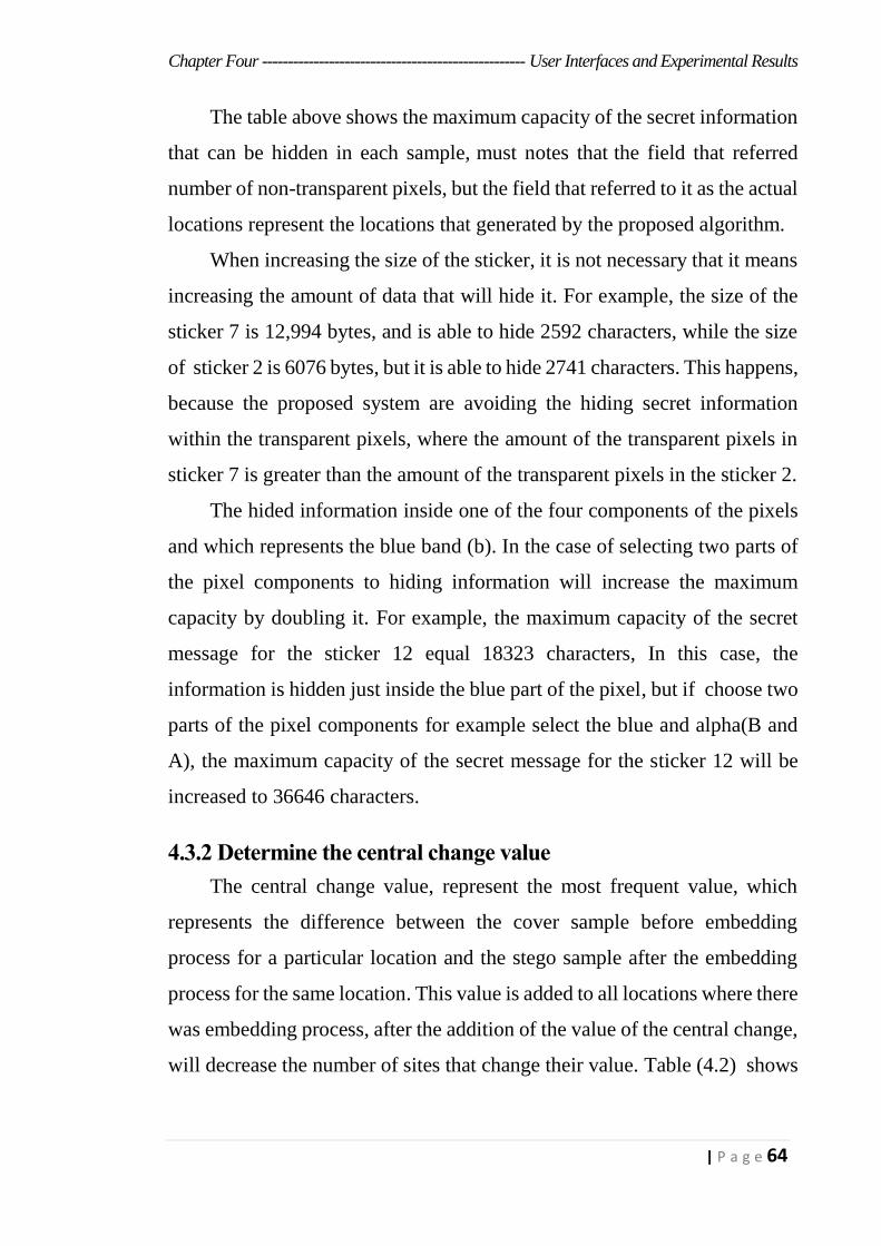
Chapter Four --------------------------------------------------- User Interfaces and Experimental Results
64 | P a g e
The table above shows the maximum capacity of the secret information
that can be hidden in each sample, must notes that the field that referred
number of non-transparent pixels, but the field that referred to it as the actual
locations represent the locations that generated by the proposed algorithm.
When increasing the size of the sticker, it is not necessary that it means
increasing the amount of data that will hide it. For example, the size of the
sticker 7 is 12,994 bytes, and is able to hide 2592 characters, while the size
of sticker 2 is 6076 bytes, but it is able to hide 2741 characters. This happens,
because the proposed system are avoiding the hiding secret information
within the transparent pixels, where the amount of the transparent pixels in
sticker 7 is greater than the amount of the transparent pixels in the sticker 2.
The hided information inside one of the four components of the pixels
and which represents the blue band (b). In the case of selecting two parts of
the pixel components to hiding information will increase the maximum
capacity by doubling it. For example, the maximum capacity of the secret
message for the sticker 12 equal 18323 characters, In this case, the
information is hidden just inside the blue part of the pixel, but if choose two
parts of the pixel components for example select the blue and alpha(B and
A), the maximum capacity of the secret message for the sticker 12 will be
increased to 36646 characters.
4.3.2 Determine the central change value
The central change value, represent the most frequent value, which
represents the difference between the cover sample before embedding
process for a particular location and the stego sample after the embedding
process for the same location. This value is added to all locations where there
was embedding process, after the addition of the value of the central change,
will decrease the number of sites that change their value. Table (4.2) shows
Chapter Four --------------------------------------------------- User Interfaces and Experimental Results
65 | P a g e
the value of central change with its amount of repetition for the secret
message with 800 bytes as a size, for the 6 samples.
Table(4. 2) the value of central change with its amount of repetition for the secret
message.
Sticker No. Central
change value
Amount of
repetition Sticker No.
Central
change value
Amount of
repetition
Sticker 2 -1 423 Sticker 8 1 604
Sticker 4 2 634 Sticker 10 7 497
Sticker 6 7 548 Sticker 12 7 554
The impact of adding the central changing value an the cover sample is
appear after the embedding process, and clearly visible in the case of hiding
within the Alpha part, where it appears in the form of gaps if they are not
adding value central change. Table (4.3) shows the effect of the adding the
central change value for the stego file. The size of the message equal 3825
byte.
A= Alpha, B= Blue and C= Central Change.
Table(4. 3)the effect of adding the central change value an the stego file.
Sticker
(Cover file).
Stego file(A). Stego file
(A+C).
Stego file(B). Stego file
(B+C).
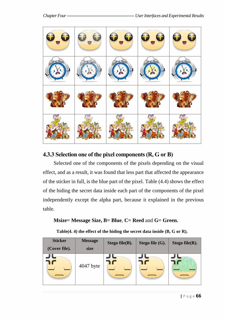
Chapter Four --------------------------------------------------- User Interfaces and Experimental Results
66 | P a g e
4.3.3 Selection one of the pixel components (R, G or B)
Selected one of the components of the pixels depending on the visual
effect, and as a result, it was found that less part that affected the appearance
of the sticker in full, is the blue part of the pixel. Table (4.4) shows the effect
of the hiding the secret data inside each part of the components of the pixel
independently except the alpha part, because it explained in the previous
table.
Msize= Message Size, B= Blue, C= Reed and G= Green.
Table(4. 4) the effect of the hiding the secret data inside (B, G or R).
Sticker
(Cover file).
Message
size
Stego file(B). Stego file (G). Stego file(R).
4047 byte
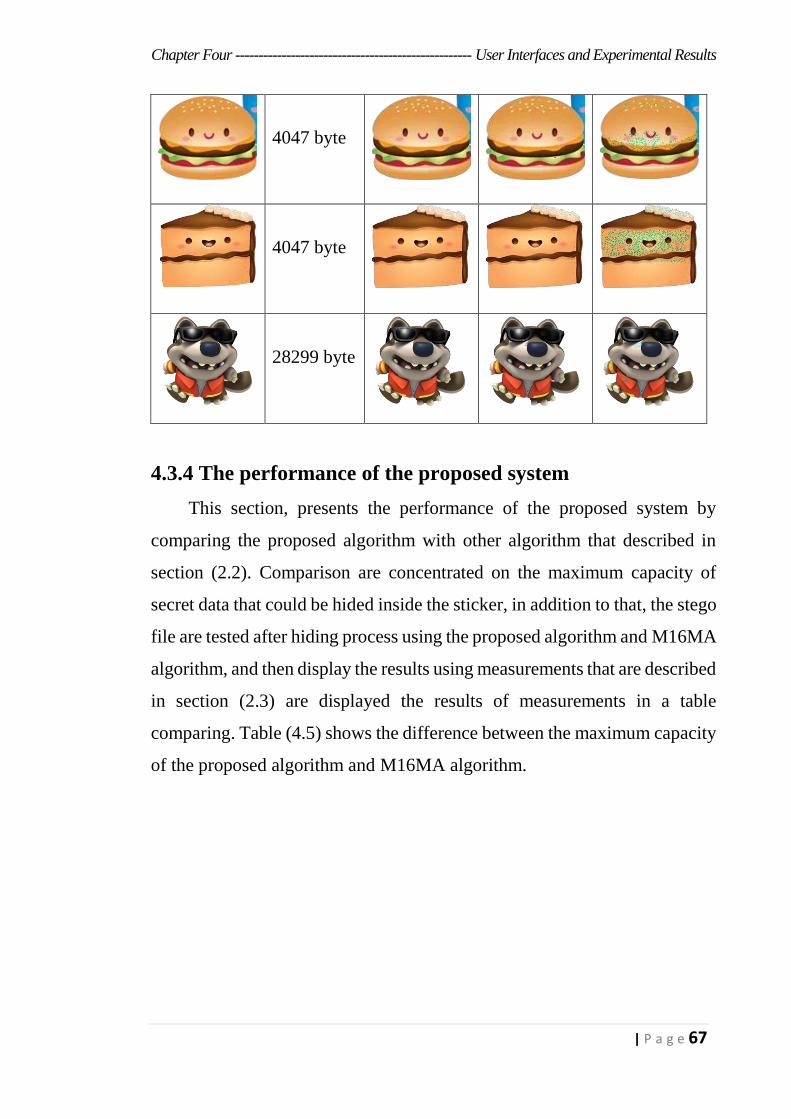
Chapter Four --------------------------------------------------- User Interfaces and Experimental Results
67 | P a g e
4047 byte
4047 byte
28299 byte
4.3.4 The performance of the proposed system
This section, presents the performance of the proposed system by
comparing the proposed algorithm with other algorithm that described in
section (2.2). Comparison are concentrated on the maximum capacity of
secret data that could be hided inside the sticker, in addition to that, the stego
file are tested after hiding process using the proposed algorithm and M16MA
algorithm, and then display the results using measurements that are described
in section (2.3) are displayed the results of measurements in a table
comparing. Table (4.5) shows the difference between the maximum capacity
of the proposed algorithm and M16MA algorithm.
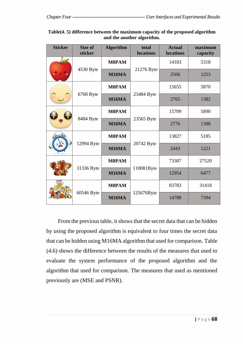
Chapter Four --------------------------------------------------- User Interfaces and Experimental Results
68 | P a g e
Table(4. 5) difference between the maximum capacity of the proposed algorithm
and the another algorithm.
Sticker Size of
sticker
Algorithm total
locations
Actual
locations
maximum
capacity
4530 Byte
M8PAM
21276 Byte
14183 5318
M16MA 2506 1253
6768 Byte
M8PAM
23484 Byte
15655 5870
M16MA 2765 1382
8484 Byte
M8PAM
23565 Byte
15709 5890
M16MA 2776 1388
12994 Byte
M8PAM
20742 Byte
13827 5185
M16MA 2443 1221
31336 Byte
M8PAM
110081Byte
73387 27520
M16MA 12954 6477
60546 Byte
M8PAM
125676Byte
83783 31418
M16MA 14788 7394
From the previous table, it shows that the secret data that can be hidden
by using the proposed algorithm is equivalent to four times the secret data
that can be hidden using M16MA algorithm that used for comparison. Table
(4.6) shows the difference between the results of the measures that used to
evaluate the system performance of the proposed algorithm and the
algorithm that used for comparison. The measures that used as mentioned
previously are (MSE and PSNR).
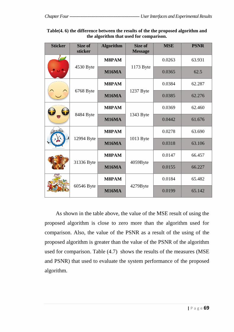
Chapter Four --------------------------------------------------- User Interfaces and Experimental Results
69 | P a g e
Table(4. 6) the difference between the results of the the proposed algorithm and
the algorithm that used for comparison.
Sticker Size of
sticker
Algorithm Size of
Message
MSE PSNR
4530 Byte
M8PAM
1173 Byte
0.0263 63.931
M16MA 0.0365 62.5
6768 Byte
M8PAM
1237 Byte
0.0384 62.287
M16MA 0.0385 62.276
8484 Byte
M8PAM
1343 Byte
0.0369 62.460
M16MA 0.0442 61.676
12994 Byte
M8PAM
1013 Byte
0.0278 63.690
M16MA 0.0318 63.106
31336 Byte
M8PAM
4059Byte
0.0147 66.457
M16MA 0.0155 66.227
60546 Byte
M8PAM
4279Byte
0.0184 65.482
M16MA 0.0199 65.142
As shown in the table above, the value of the MSE result of using the
proposed algorithm is close to zero more than the algorithm used for
comparison. Also, the value of the PSNR as a result of the using of the
proposed algorithm is greater than the value of the PSNR of the algorithm
used for comparison. Table (4.7) shows the results of the measures (MSE
and PSNR) that used to evaluate the system performance of the proposed
algorithm.

Chapter Four --------------------------------------------------- User Interfaces and Experimental Results
70 | P a g e
Table(4. 7) the results of the measures (MSE and PSNR) that used to evaluate the
system performance of the proposed algorithm.
Sticker Message 1
250 byte
Message 2
500 byte
Message 3
750 byte
Message 4
1000 byte
Message 5
1250 byte
25KB
MSE:
N/A
MSE:
0.0019
MSE:
0.0028
MSE:
0.0036
MSE:
0.0048
PSNR:
∞
PSNR:
75.343
PSNR:
73.66
PSNR:
72.567
PSNR:
71.318
31KB
MSE:
N/A
MSE:
0.0018
MSE:
0.0027
MSE:
0.0036
MSE:
0.0046
PSNR:
∞
PSNR:
75.578
PSNR:
73.817
PSNR:
72.567
PSNR:
71.503
49KB
MSE:
N/A
MSE:
0.0018
MSE:
0.0027
MSE:
0.0035
MSE:
0.0044
PSNR:
∞
PSNR:
75.578
PSNR:
73.817
PSNR:
73.690
PSNR:
71.696
60KB
MSE:
N/A
MSE:
0.0017
MSE:
0.0026
MSE:
0.0035
MSE:
0.0041
PSNR:
∞
PSNR:
75.826
PSNR:
73.981
PSNR:
72.690
PSNR:
72.002
73KB
MSE:
N/A
MSE:
0.0016
MSE:
0.0025
MSE:
0.0033
MSE:
0.0041
PSNR:
∞
PSNR:
76.089
PSNR:
73.151
PSNR:
72.945
PSNR:
72.002
The cover file that used in the proposed system is Webp with lossless
compression, therefore the size of the cover file after the embedding process
will be increasing, Table (4.8) shows the difference of increased size
between the cover file and the stego file.
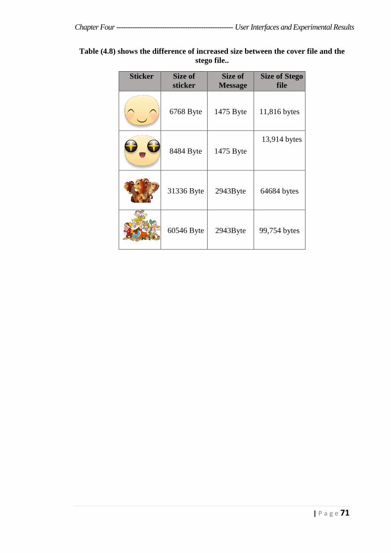
Chapter Four --------------------------------------------------- User Interfaces and Experimental Results
71 | P a g e
Table (4.8) shows the difference of increased size between the cover file and the
stego file..
Sticker Size of
sticker
Size of
Message
Size of Stego
file
6768 Byte 1475 Byte 11,816 bytes
8484 Byte 1475 Byte
13,914 bytes
31336 Byte 2943Byte 64684 bytes
60546 Byte 2943Byte 99,754 bytes

Chapter Five
Conclusions And
Suggestion For Future
Work

Chapter Five --------------------------------------------- Conclusions And Suggestion For Future Work
72 | P a g e
Chapter Five
Conclusions and Suggestion for Future Work
5.1 Conclusions
From this thesis, many important points are observed and concluded.
The following are the most important points:
1. Using WebP images (Stickers) as a cover file for secret data, especially
the secret messages, is more safer, because this format is used as
emoticons and frequently used in conversation applications.
2. Transferring the WebP images, whether they carry secret messages or not,
over the Internet is faster than other formats because their sizes are small.
3. It is impossible to distinguish WebP images that containing the secret
messages in different sizes with the naked eye, because the dimensions of
the WebP images are small.
4. The embedding inside of the alpha channel in the WebP images without
adding the central change value, distort the image significantly, as shown
in Table (4.3).
5. The retrieved message after extracting from WebP has no distortion.
6. The comparison of the proposed algorithm with M16MA algorithm as
shown in table (4.6). The results of the proposed algorithm are better than
M16MA algorithms.
Chapter Five --------------------------------------------- Conclusions And Suggestion For Future Work
73 | P a g e
5.2 Suggestions for Future Work
For the enhancement of any system, the developer of any system
should keep pace with and continuous improvements, the proposed
improvements to the system as follows:
1. Develop the system to allow all versions of the WebP images as a cover
file.
2. Develop the system in a manner that accepts the embedding of all types
of data (Image, Video, Sound, etc.).
3. Develop the system to compatible with the applications of conversation
(Viber, WhatsApp, Messenger, etc.).
4. Develop the system in a way that accepts the embedding of secret data
on more than one cover file.
References
References
[Ark11] Arko K., Kaushik C., et al. "Audio Steganography Using
Mod 4 Method(M4M)." Journal of Computing 3.8, pp. 30-38,
(2011).
[Asm16] Asma C., Belgacem B., et al. "Software Application for
Simulation-Based AES, RSA and Elliptic-Curve
Algorithms." Advanced Technologies for Signal and Image
Processing (ATSIP), 2nd International Conference on. IEEE,
pp. 77-82, (2016).
[Asw14] Aswathy B., and Resmi R. "Modified RSA Public Key
Algorithm." Computational Systems and Communications
(ICCSC), First International Conference on. IEEE, pp. 252-
255, (2014).
[Bre02] Bret D. "A detailed look at Steganographic Techniques and
their use in an Open-Systems Environment." Sans Institute,
pp. 1-9, (2002).
[Cha13] Chandrakant B. "Payload Capacity Enhancement In The
Field of Steganography By Using Mobile Application Based
Stego Technique." i-Manager's Journal on Software
Engineering 7.4, pp. 31-36, (2013).
[Dal12] Dalal N., Mohammad S."A New Steganographic Method for
Embedded Image In Audio File." International Journal of
Computer Science and Security 6.2, pp. 135-141, (2012).
[Deb14] Debiprasad B., Kousik D., et al. "A Novel Secure Image
Steganography Method Based On Chaos Theory In Spatial
Domain." International Journal of Security 3.1,(2014).
[Die11] Dieter G. "Computer Security." Chichester, Wiley, third
edition, (2011).

[Gia12] Giaime G., Maurizio P., et al. "Objective Assessment of the
WebP Image Coding Algorithm." Signal Processing: Image
Communication 27.8, pp. 867-874, (2012).
[Goo10] Google Developers, "A new image format for the Web |
WebP." Accessed May 28, 2017, (2010).
Available at: https://developers.google.com/speed/webp/.
[Hay14] Hayfaa A., Robiah A., et al."Combining cryptography and
steganography for data hiding in images." Applied
Computational Science, pp. 128-135, (2014).
[Hus04] Husrev T., Ali N., et al. "Data hiding fundamentals and
applications: content security in digital multimedia."
Academic Press (2004).
[Kav10] Kavun E. "A Compact Cryptographic Processor For IPSEC
Applications" MS, Middle East Technical University (2010).
[Kha14] Khalid I., et al. "A Crypto-Steganography: A Survey."
International Journal of Advanced Computer Science and
Applications 5.7, pp. 149-155, (2014).
[Kha15] Khalid I., et al. "Study of Cryptography and Steganography
System." International Journal Of Engineering And Computer
Science 4.8, pp. 13685- 13687 , (2015).
[Lis16] Lisa K. "Threats and benefits of data-hiding methods used
in smart mobile devices." Doctoral dissertation, Utica
College (2016).
[Man15] Manjula G., and Ajit D. "A novel hash based least significant
bit (2-3-3) image steganography in spatial domain."
International Journal of Security, Privacy and Trust
Management (IJSPTM) 4.1, pp. 11-20, (2015).
[Meh17] Mehdi H., Ainuddin W., et al. "A data hiding scheme using
parity-bit pixel value differencing and improved rightmost
digit replacement." Signal Processing: Image
Communication 50 (2017): pp. 44-57.
[Mic12] Michael E.,Herbert J. "Principles of information security."
4th Edition, Cengage Learning (2012).
[Mih12] Mihir H."Cryptogrphy-Combination of Cryptography and
Steganography With Rapidly Changing Keys." International
Journal of Emerging Technology and Advanced Engineering
2.10, pp. 329-332, (2012).
[Mil16] Mile M., Miroslav M., et al. " Impact Of Jpeg-Webp
Conversion On The Characteristics Of The Photographic
Image." Tehnički vjesnik 23.2, pp. 505-509, (2016).
[Mil17] Mils E." One Time Pad Encryption The unbreakable
encryption method." mils electronic (2017).
[Moh16] Mohammed J., Atef A., et al. "A Secure Robust Gray Scale
Image Steganography Using Image Segmentation." Journal
of Information Security 7.03, pp. 152-164, (2016).
[Mor05] Morkel, T., Jan H., et al. "An overview of image
steganography." University of Pretoria (2005).
[Nar16] Narmatha M., and Venkata K. "Study on Android Operating
System And Its Versions." International Journal of Scientific
Engineering and Applied Science (IJSEAS) 2.2, pp. 439-445,
(2016).
[Nic09] Nicholas G. "Past, present, and future methods of
cryptography and data encryption." Research Review.
University of Utah (2009).
[Phi08] Philip B., and Hans G. "Image steganography and
steganalysis." MS, Department Of Computing, Faculty of
Engineering and Physical Sciences, University of Surrey,
Guildford, Surrey, United Kingdom (2008).
[Rah14] Rahul Y. "Message Security Using Cryptography And Lsb
Algorithm Of Steganography." Cancer Research and
Oncology 2.11, pp. 25-32, (2014).
[Sou11] Souvik B., Gautam S. et al. "A Novel Audio Steganography
Technique by M16MA." International Journal of Computer
Applications 30.8, pp. 26-34, (2011).
[Sri10] Srinivasan N., Kishore B., et al. "Formal Method of
Encryption Using 9’S Complement." International Journal
of Computer Applications 8.5, (2010).
[Tre12] Trevor B. "Check Image Processing: WebP Conversion and
MICR Scan Android Application." California Polytechnic
State University (2012).
[Tsa05] Tsang P., and M. Patrick. "Cryptography in privacy-
preserving applications." MS, The Chinese University of
Hong Kong, (2005).
[Ven10] Venkata S. "Cryptography and steganography."
International Journal of Computer Applications 1.12, pp. 63-
68, (2010).
[Vip13] Vipula M., and Suresh Kumar. "Enhancing data security
using video steganography." International Journal of
Emerging Technology and Advanced Engineering 3.4, pp.
549-552, (2013).
[Wil15] William, and Lawrie Brown. "Computer security Principles
and Practice." Third Edition (2008).
[Wit16] Wittkop and Jeremy. "Building a Comprehensive IT
security program." (2016).
[Zai14]
Zainab J. "Selective Watermarking Based on Interface
Coding and Mean Modulation for Sprite Blocks." MS,
Baghdad of University (2014).
[Zho04] Zhou W., et al. "Image quality assessment: from error
visibility to structural similarity." IEEE transactions on
image processing 13.4, pp. 600-612, (2004).

صخ لالم
تنسيقصورة استخدام علىبرامج WebP انتشار وخاصة الإنترنت، علىشبكة
وسائلالتواصلالاجتماعيوبرامجالمحادثة،لذلكعندماترسللهممراراوتكرارالاتثير
مجالأمنيةالبيانات.فيهذهالأطروحة،تماقتراحفيالشك،مماجعلهانقطةقوةلتستغل
تقنية باستخدام السرية الرسائل لحماية المعلوماتنظام الرسائلاخفاء إخفاء خلال من
صورة تنسيق داخل سميتWebPالسرية التي و مقترحة خوارزمية باستخدام
M8PAM واحدةمنالغلافوفقابكسلتخفيالخوارزميةالمقترحةكلثلاثبتاتفي.
.لخوارزميةمقترحةلاختيارمواقعالاخفاءفيملفالغطاء
البكسلالغيرتمتطبيقثلاثةمستوياتعلىالنظامالمقترح؛المستوىالأول،لتحديد
ثم فيشفاف، البياناتالسرية فيإخفاء محددة خوارزميةمواقع باستخدام ملفالغطاء
بتاتمنالرسالةالسريةثلاثكلخفاء.المستوىالثاني،تشفيرمقترحةلاختيارمواقعالا
الثالث، المستوى وأخيرا عشوائية. ارقام توليد دالة باستخدام توزيعها إعادة طريق عن
طريقة لتشفير(RSA)استخدام قبل السرية الرسالة الى اضافتها و معينة تنفيذمقدمة
.إخفاءالبياناتعمليات
نجاحالخوارزميةالمقترحة،تمتمقارنةالخوارزميةالمقترحةمعللتأكدمنضمان
أخرى خوارزمية المقترحة(M16MA)تدعى الخوارزمية ميزة النتائج أظهرت حيث ،
هما مختلفين مقياسين (MSE,PSNR)باستخدام , ان اناظهرتهماتطبيقنتيجةحيث
مطبقةعلىبيناتسرية(66.457)ساوييPSNR(و0.0147)ساوييMSEمتوسط
معدلإخفاءالبياناتوكذلكانبايت(.31336بايت(وحجمالغطاء)4059)يبلغحجمها
٪.66.66يساوي

عنطريقWebPالاخفاءبأستخدامصورةتقنية
لتطبيقاتالاندرويدM8PAMاستخدامخوارزمية
ةرسال
النهرينفيجامعةعلومالىكليةالمقدمه كجزءمنمتطلباتنيلدرجةالماجستير
علومالحاسوبفي
مـــــنقبـــــل
مصطفىباسممحمود (2013علوم حاسبات, بكالوريوس)
اشراف
باننديمذنون.د.أ
م2017هـ1439
جمهوريةالعراق
والبحثالعلميوزارةالتعليمالعالي
النهرينجامعة
كليةالعلوم