€¦ · web view · 2010-02-13sailor n1407 is a de power supply intended to supply a sailor ssb...
TRANSCRIPT


CONTENTS:
1. GENERAL DESCRIPTION 1.1 TECHNICAL DATA 1.2 PRINCIPLE OF OPERATION
2. SERVICE 2.1 MAINTENANCE 2.2 RECOMMENDED MEASUREMENT INSTRUMENTS 2.3 PERFORMMJCE CHECK 2.4 SELF MADE TEST LOAD 2.5 NECESSARY ADJUSTMENTS AFTER REPAIR 2.6 TROUBLE SHOOTING 2.7 PIN CONFIGURATION
3. CIRCUIT DESCRIPTION AND DIAGRAMS WITH MEASUREMENTS 3.1 INPUT FILTER (MODULE 400) 3.2 POWER UNIT I 3.3 POWER UNIT II 3.4 BLOWER CONVERTER (MODULE 300)
4. COMPONENT LOCATIONS: 4.1 CAPACITOR UNIT (MODULE 100) 4.2 PU I AND PU II CONTROL UNIT (MODULE 200) 4.3 BLOWER CONVERTER (MODULE 300) 4.4 INPUT FILTER AND FUSES (MODULE 400) 4.5 CHASSIS MOUNTING (MODULE 500) 4.9 DISASSEMBLING FROM Tl130 4.10 MAIN DIAGRAM
5 PART LISTS

CONTENTS: 1. GENERAL DESCRIPTION 1.1 TECHNICAL DATA 1.2 PRINCIPLE OF OPERATION

1. GENERAL DESCRIPTION
SAILOR N1407 is a De power supply intended to supply a SAILOR SSB short wave station from program 1000/B, when the set has to be supplied from a 24V battery.
SAILOR N1407 is an integral part of the transmitter T1130 and all the con-trols of the power supply takes place via electrical wires.
SAILOR N1407 The information to control N1407 comes from the short wave station and is established from the commands given to the set via the push buttons in the rack and from the mode selected on the exciter and receiver by the operator.
SAILOR N1407 with MAIN SWITCH in position RX-ONLY. Only the receiver is in operation and low power consumption is achieved.
SAILOR N1407 is provided with a thermostat which starts the fans for the power supply, if the temperature inside the power supply gets too high

The power supply N1407 delivers all necessary voltages to a SAILOR 1000/B SSB short wave set with an output power of 400 W PEP in the frequency range 1.6 - 27.5 MHz. OUTPUT VOLTAGES: DC stabilized:
22V +/- 2% I max 3.2 A8V +/- 2% I max 2.0 A
28V +/- 2% I max 3.4 A38V +/- 2% I max 14 A
DC unstabilized:
1.1. TECHNICAL DATA
OPERATION TEMPERATURE RANGE: -150C to +550C
COOLING: As long as the power supply supplies a receiver and an not keyed transmitter, the cooling takes place via convection only.
When the transmitter is keyed or the internal temperature of the power supply is above +550C the blowers inside the T1130 unit are continuously running and cooling down the power supply and the transmitter. When the temperature falls below + 45ºC the blowers stop.
If temperature in transmitter is too high, the power supply is reduced from 38V to 30V. If temperature is further increasing, the Power Unit II is blocked and blowers start. When temperature is decreased blowers stop, and Power Unit II is unblocked again.

-45V Imax 0.15A
AC unstabilized:
V blower = V im – 2 x V sat, I max 2A
frequency 60 Hz Nominal voltage 24 V
Extreme voltage 21.6 - 31.2 V
by 26.4V DC input
2-tone approx. 30 A A3J approx. 17 A A3H approx. 24 A R.O. approx. 2.5A
INPUT VOLTAGE:
INPUT CURRENT:

1.2. PRINCIPLE OF OPERATION The power supply N1407 consists of three power supplies.
Power Unit I is a 400 Hz DC converter which delivers low power voltages for receiver, exciter and transmitter. Power Unit II is also a 400 Hz push-pull converter which delivers high power to the transmitter. The blower converter produces an AC voltage for the blowers.
PU I is working when the set is switched on.
PU II is only working when PU I is switched on and the transmitter is keyed. N1407 is
switched ON/OFF by the switches in H1235 rack system.
Maximum loads for the output voltages:
38V : IL max = 14 A RL = 2.7 ohm (600 W)PU II
28V : IL max = 3.4A RL = 8.2 ohm (100 W)
22V : IL max = 3.2A RL = 6.8 ohm ( 75 W)
PU I 8V : IL max = 2.0A RL = 4.0 ohm ( 20 W)
-45V : IL max = 0.15A RL = 300 ohm ( 10 W)
It is necessary to have all outputs loaded with their max. load, when the current limiters are adjusted.
To ensure proper regulation it is necessary that the power supply has a minimum load.
PU I: min. load for 22V output is approx. 22 ohm (no load at 8V and at -45V output)
PU II : min. load to 38V output is approx. 50 ohm (no load at 28V output)

CONTENTS: 2. SERVICE 2.1 MA I NTENANCE 2.2 RECOMMENDED MEASUREMENT INSTRUMENTS 2.3 PERFORMANCE CHECK 2.4 SELF MADE TEST LOAD 2.5 NECESSARY ADJUSTMENTS AFTER REPAIR 2.6 TROUBLE SHOOTI NG 2.7 PIN CONFIGURATION

When the SAILOR Short Wave Set type 1000/8 has been correctly installed, the maintenance of the power supply can dependent on the environments and working hours be reduced to a performance check at the service workshop at intervals not exceeding 5 years. A performance check list is enclosed in the PERFORMANCE CHECK section. Also
inspect cables and plugs for mechanical defects and corrosion.
Any repair of the set should be followed by a check described in the section NECESSARY ADJUSTMENTS AFTER REPAIR.
2.3. PERFORMANCE CHECK 2.2. RECOMMENDED MEASUREMENT INSTRUMENTS 2.1. MAINTENANCE 2. SERVICE
MULTIMETER . . . . . . . . . . PHILIPS PM2505
OSCILLOSCOPE . . . . . . . . . PHILIPS PM3214
1. N1407 is mounted in Tl130 (1000/B rack). 2. Connect 24V DC to plug Pl03.
3. Push "RX-ONLY" (switches on PU I).
4. Check 22V output voltage. If necessary then adjust to 22.0V with R238.
5. Check 8V output voltage. If necessary then adjust to 8.OV with R241.
6. Check -45V output voltage to approx. -40V.
7. Push "ON" button and press key.
8. Check 28V and 38V output voltages. If necessary then adjust to 28V with
R271 and to 38V with R259.
9. Current limiters cannot be adjusted.
10. While pressing the key or short-circuiting the thermal breaker TB501 check that both blowers are running.
11. When the blowers are running then check the blower converter. Measure with oscilloscope that the output frequency is 60 Hz (16.67 ms) and the pulse time is 7.5 ms.

SELF MADE TEST LOAD FOR NI407 / NI409 I.
2.4 SELF MADE TEST LOAD.

2.5. NECESSARY ADJUSTMENTS AFTER REPAIR
When PU II is switched on, it is always necessary to cool the switch tran-sistors T504 and T505 and the output rectifier D505. It is recommended to mount N1407 in a Tl130 chassis with a blower to cool the power supply.
1. Remove the connection wire from the collectors of T504 and T505 to the transformer TR502.
2. Check the output voltage of PU I.
3. Connect scope ground to negative input voltage (negative pole of C503) and scope probe to the base of T504.
4. Replace F402.
5. Switch on PU I and PU II and check the base driver (see fig. on diagram).
6. Switch off PU I and PU II and connect scope probe to the base of T505.
7. Switch on PU I and PU II and check the base driver (see fig. on diagram).
8. Switch off PU I and PU II.
9. Connect the transformer TR502 to the collectors of T504 and T505.
10. Switch on PU I and PU II.
11. Turn R243 out of current limiting. Adjust 38V output with R259 to 38.0V. Adjust 28V output with R271 to 28.0V. Adjust current limiter with R243 so the 38V output is 35.5V with full load at 38V output and at 28V output.
12. Let the power supply work for about an hour and then check again the output voltages. Adjust if there has been some deviation.
(using SELF MADE test load)
POWER UNIT I
1. Connect SELF MADE test load to N1407 outputs.
2. Remove fuse F402.
3. Connect 24V DC to plug Pl03.
4. Switch on PU I.
5. Adjust 22V output with R238 to 22.0V.
6. Adjust 8V output with R241 to 8.0V.
7. Check -45V output (approx. -40V).
8. Switch off PU I.
POWER UNIT II

BLOWER CONVERTER 1. Switch on PU I and PU II. The blowers have to run. 2. Connect scope ground to the negative pole of the input voltage and scope
probe to IC302 pin 1 (or pin 2). Adjust with R305 so that the frequency is 60 Hz (16.67 ms).
3. Connect scope probe to IC303 pin 3. Adjust with R311 so that the pulse time is 7.5 ms.
Failure in Power Unit I. 1. Bad connections in plug P103 or J101.
2. Fuse F401 is blown out.
a) The converter transistors T501 and T502 or the output stage in the blower converter are short-circuited.
3. PUI will not start up.
a) Check the relay RE201 and the voltage to it.
4. The converter starts up, but the output voltages are wrong.
a) Check the outputs severally.
b) Failure in the relays RE203, RE204 and RE205 or in the transistors T205 and T206.
Failure in Power Unit II. 1. Relay RE202 is not activated when handset key is pressed.
a) PU I is out of function.
b) Handset key is out of function.
2. Supply is blocked.
a) Temperature protection unit in Tl130 blocks the power supply because of overheating of the transistors in the power amplifier in T1130. Check also the blowers and air filter.
b) Bad connection of J102.
c) Over- and under voltage shut-down at IC201.
3. Supply starts up, but goes into "hiccup mode".
a) Wrong adjustment of current limiter R243.
b) Output voltage is short-circuited or overloaded.
c) To low input voltage.
2.6. TROUBLE SHOOTING

Failure in the Blower Converter.
1. Blowers will not stop.
a) Toa high temperature in the power supply. b) Tea high temperature in the transmitter. c) Bad connection in J102. d) Thermal breaker is short-circuited. e) Dirty air filter.
2. Blowers will not run. a) On/off circuit consisting of IC301, T301 and T302 is out of function. b) Wrong frequency of IC301. c) Wrong pulse time of IC303.


PIN CONFIGURATION cont.

CONTENTS: 3. CIRCUIT DESCRIPTION AND DIAGRAMS WITH MEASUREMENTS 3.1 INPUT FILTER (M0DULE 400) 3.2 POWER UNIT I
3.3 POWER UNIT II
3.4 BLOWER CONVERTER (MODULE 300)

3. CIRCUIT DESCRIPTIONS AND DIAGRAMS WITH MEASUREMENTS 3.1. INPUT FILTER (MODULE 400) The filter consists of capacitors and a filter choke L401 to suppress switch noise. It fulfills the CISPR noise regulation.
The fuse F401 protects Power Unit land the blower converter. Fuse F402 protects Power Unit 11. The diodes D401 and D402 protects against reverse polarity of the input voltage to P103.
3.2. POWER UNIT I In the rack system H1235 the terminals J101/32 and J101/33 are short circuited and relay RE201 is activated when starting up the PU I. The converter, consisting of TR201, TR501, T501 and T502, starts up and delivers voltage to the three secondary outputs. -45V output is only rectified in D205 and is not regulated. The voltage is -34 to -54V depending of the input voltage. -45V to the receiver is switched on/off by the transistors T205 and T206. They are controlled by relay RE203 which also switches on/off the 22V and 8V to the receiver.
22V output is regulated after the switch mode principle by IC202 and is adjusted with R238. Transistor T203 turns on and the current flows through L501 and L502 to the load. The voltage increases at pin 4 and IC202 turns off T203. The current flows continuously in L501 and back through D210. The voltage decreases at pin 4 and IC202 turns on T203 again. The regulator is then self oscillating. R233 forms a current limiter.
8V output is a linear series regulator controlled by IC203. The output voltage is adjusted with R241. IC203 is supplied from 22V output which means that 8V is present only if 22V is present.
The relays RE204 and RE205 switch on the voltage to Tl130 and to the exciter.
3.3. POWER UNIT II When the transmitter is keyed the relay RE202 switches on. The antenna tuner AT1500 gets 22V supply via J101 pin 7. The voltage at IC201 pin 6 and pin 7 is determined by R204, R205 and R206. These inputs form an over and under voltage protection. "Over voltage" shut down occurs at approx. 33.5V input. "Under voltage" shut down occurs at approx. 16.5V input.
Switching on PU II means that C207 can be charged by IC201 and create a soft start function at pin 15 to limit the peak current in the switch transistors and the output rectifier.
The IC201 has two outputs, pin 12 and pin 13, working as push-pull and being active low. The switch frequency is approx. 450 Hz, but the frequency of the internal saw tooth oscillator is approx. 900 Hz, determined by R207 and C206.
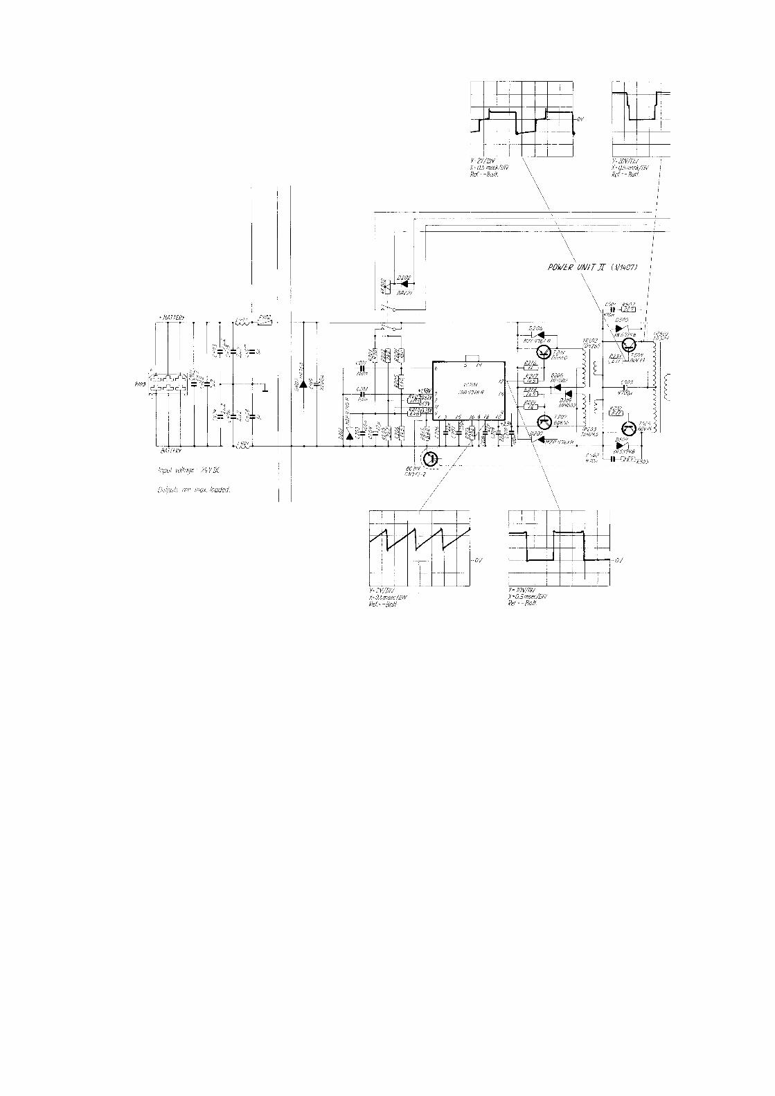
Regulation of the duty-cycle is done by varying the voltage at pin 4, This regulation signal te control the output current and output voltage is created in IC204, Voltage supply for IC201 is regulated by means of R201 and D201.
The controlled square wave from the outputs of IC201 is led to the switch transistors T504 and T505 via the driver transistors T201 and T202 and the driver transformers TR202 and TR203. The diodes D206 - D209 clamp the over voltage transients from the driver transformers. The diodes D503 and D504 together with C501, R502, C502 and R503 protect the switch transistors against transients and unwanted oscillations. C503 reduces the ripple to the input filter.
The output voltage is rectified in D505. R504, C504 and R505 protect against unwanted oscillations and transients. The choke L503 is an energy reservoir. Together with Cl0l - Cl06 it is smoothing the output current. The output voltage of 38V is regulated by IC204a. The reference voltage is made by D213. Adjustment is done with R259. lf the output voltage in-creases, pin 1 will go low. Via IC201, IC201 pin 4 is pulled down and this reduces the duty-cycle and thus the output voltage. R266 has to be connected to ground to get 38V. For supply reduction to the transmitter, R266 is released from ground via the thermal protection unit in Tl130 and the output voltage is approx. 30V.
A current limiter is performed by IC204b. Rl0l is the current sensor and is made of constantan wire. lf the current exceeds the level determined by R243, the output pin 7 goes high and turns on T207, which again pulls down the reference voltage for IC204a. This means that the output voltage to the transmitter will be reduced.
The current limiter is made slow with C226 to pre vent the variation from the modulation of the transmitter. lt cannot protect the output transistors or rectifier against short circuit of the output.
IC206 delivers a regulated 8V supply for the voltage regulator and current limiter circuit.
The 28V output is regulated by IC205 and is adjusted with R271. Transistor T208 turns on and the current flows through L504 to C231 and the load. The voltage increases at pin 4 and IC205 turns off T208. The current flows continuously in L504 and back through D214. The voltage will decrease at pin 4 and IC205 turns on T208 again. The regulator is then self oscillating. R268 forms a current limiter.

T301 + BAT
}101/32 ~ }1DJ!33 - 0/ STAPT J PUI HOI
3.4. BLOWER CONVERTER
When PU I is started up the oscillator IC301 is always running. The output stage and also the blowers are switched on/off by means of IC30l and IC303. The supply for the blower converter control circuit is regulated to 12V by means of R322 and D301.
The frequency of the oscillator IC301 is 120 Hz and is determined by means of IC301, C303, R305, R306 and R307. The frequency is adjusted with R305. The output pulses from IC301 pin 3are led to IC303 pin 2 and to T303 which inverts the signal before it is led to IC302 pin 3, which produces a square wave signal of 60 Hz to the output stage. In order to avoid the simultaneous conducting of all four output transi-stors T506 - T509, a dead time is performed with IC303, which pulls down the base of T304 and T305 via D302 and D303. This will block the output stage.
If IC301 is not activated, IC303 pin 4 is grounded via R313 and the dead time is 100 % and then the output stage is off. If IC303 pin 4 is pulled high via IC301, the output pulse from IC303 pin 3 is 7.5 ms, which is ad-justed with R311 and the blowers are running. The output stage is a bridge coupled push-pull stage and consists of four Darlington power transistors T506 - T509 driven by the transistors T304 and T305.
By means of IC301 the blowers can be switched on in three ways. IC301 is always biased with 22V from PUI.
If temperature in the whole power supply exceeds 550C, the thermal breaker TB501 is switched on and starts the blowers until the temperature is approx. 40ºC.
When transmitter is keyed, diode D306 is grounded via handset key and the blowers are running The temperature protection unit in the transmitter unit breaks the con-nection between +22V and supply block terminal at Jl02. This turns off T301 which again turns on IC301 and thus also the blowers.


CONTENTS:
4. COMPONENT LOCATIONS: 4.1 CAPACITOR UNIT (MODULE 100) 4.2 PU I AND PU II CONTROL UNIT (MODULE 200) 4.3 BLOWER CONVERTER (MODULE 300) 4.4 INPUT FILTER AND FUSES (MODULE 400) 4.5 CHASSIS MOUNTING (MODULE 500) 4.9 DISASSEMBLING FROM Tl130 4.10 MAIN DIAGRAM

Component location


4.1. CAPACITOR UNIT (MODULE 100)
WIRECOLOURS
0 = BLACK 1 = BROWN 2 = RED 3 = ORANGE4 = YELLOW5 = GREEN6 = BLUE 7 = VILOLET8 = GREY 9 = WHITE
Ex. BROWN / WHITE = 19

4.2. PU I AND PU II CONTROL UNIT (MODULE 200)
4.5. CHASSIS MOUNTING (MODULE 500)


4.3. BLOWER CONVERTER (MODULE 300)
WIRECOLOURS
0 = BLACK 1 = BROWN 2 = RED 3 = ORANGE4 = YELLOW5 = GREEN6 = BLUE 7 = VILOLET8 = GREY 9 = WHITE Ex. BROWN / WHITE = 19
WIRECOLOURS
0 = BLACK 1 = BROWN 2 = RED 3 = ORANGE4 = YELLOW5 = GREEN6 = BLUE 7 = VILOLET8 = GREY 9 = WHITE Ex. BROWN / WHITE = 19
4.2. INPUT FILTER AND FUSES (MODULE 400) WIRECOLOURS
0 = BLACK 1 = BROWN 2 = RED 3 = ORANGE4 = YELLOW5 = GREEN6 = BLUE 7 = VILOLET8 = GREY 9 = WHITE Ex. BROWN / WHITE = 19

1.9. DISASSEMBLING FROM T1130
.;'


CONTENT
S:
5 PART LISTS

Capacitor unit N1407 (100) 1/1
Symbol Discripion Manufact.
C101 Capacitor, electrolytic 2200 uF -10/+50% 40V ROE EG 03 MG 422G C102 Capacitor, electrolytic 2200 uF -10/+50% 40V ROE EG 03 MG 422G C103 Capacitor, electrolytic 2200 uF -10/+50% 40V ROE EG 03 MG 422G C104 Capacitor, electrolytic 2200 uF -10/+50% 40V ROE EG 03 MG 422G C105 Capacitor, electrolytic 2200 uF -10/+50% 40V ROE EG 03 MG 422G C106 Capacitor, electrolytic 2200 uF -10/+50% 40V ROE EG 03 MG 422G
Rl01 Resistor S.P. TL379
PU I and PU II unit N1407 (200) 1/5
Symbol Description Manufact.
C201 capacitor, polyester 100 nF +/-10% 100V Siemens B32510-D1104-K C202 capacitor, polyester 100 nF +/-10% 100V Siemens B3251O-D1104-K C203 capacitor, polyester 100 nF +/-10% 100V Siemens B32510-D1104-K C204 capacitor, electrolytic 22 uF +/-20% 25V ROE EKI 00 AA 222E C205 capacitor, polyester 100 nF +/-20% 400V ERO MKT 1822-410-406 C206 capacitor, polyester 22 nF +/-5% 400V ERO MKT 1822-322-404 C207 capacitor, polyester 330 nF +/-20% 63V ERO MKT 1818-433-066 C208 capacitor, polyester 22 nF +/-5% 400V ERO MKT 1822-322-404 C209 capacitor, electrolytic 22 uF +/-20% 25V ROE EKI 00 AA 222E C210 capacitor, polyester 100 nF +/-10% 100V Siemens B32510-Dl104-K C211 capacitor, polyester 220 nF +/-20% 100V ERO MKT 1822-422-016 C212 capacitor, polyester 220 nF +/-20% 100V ERO MKT 1822-422-016 C213 capacitor, polyester 220 nF +/-20% 100V ERO MKT 1822-422-016 C214 capacitor, electrolytic 470 uF -10/+50% 50V ROE EKM 00 JG 347H C215 capacitor, electrolytic 2200 uF -10/+50% 16V ROE EKM 00 JG 422D C216 capacitor, electrolytic 100 uF -10/+50% 63V ROE EKM 00 DE 310J C217 capacitor, electrolytic 10 uF +/-20% 35V ROE EKI 00 AA 210F C218 capacitor, polyester 47 nF +/-10% 250V Siemens B32510-D3473-K C219 capacitor, polyester 100 nF +/-10% 100V Siemens B32510-D1104-K C220 capacitor, electrolytic 220 uf -10/+50% 25V ROE EKR 00 FE J22E C221 capacitor, electrolytic 100 uF -10/+50% 16V ROE EKM 00 CC 3100 C222 capacitor, electrolytic 220 uF –10/+50% 25V ROE EKR 00 FE 322E C223 capacitor, electrolytic 1000 uF -10/+50% 25V ROE EKM 00 JG 410E C224 capacitor, ceramic 10 nF -20/+00% 50V KCK HE70 SJYF 103Z C225 capacitor, ceramic 10 nF -20/+80% 50V KCK HE70 SJYF 103Z C226 capacitor, polyester 1 uF +/-10% 100V Siemens B32511-01105-K C227 capacitor, electrolytic 10 uF +/-20% 35V ROE EKI 00 AA 210F C228 capacitor, polyester 100 nF +/- 10% 100V Siemens 832510-01104-K C229 capacitor, polyester 220 nF +/-10% 100V Siemens B32511-01224-K C230 capacitor, polyester 100 nF +/-10% 100V Siemens B32S10-Dl104_K C231 capacitor, electrolytic 470 uF -10/+50% 50V ROE EKM 00 JG 347H C232 capacitor, polyester 220 nF +/-10% 100V Siemens B32511-D1224-K

PU I and PU II unit N1407 (200) 2/5 Symbol Description Manufact.
D201 Diode, zener 12V +/-5% 2.5W Motorola MZP4742A D202 Diode Philips BAV21 D203 Diode Motorola MR750 D204 Diode Motorola MR750 D205 Diode bridge G. I. 2 KBP 04 D206 Diode, zener 75V +/-5% 2.5W Motorola MZP4761A D207 Diode, zener 75V +/-5% 2.5W Motorola MZP4761A D208 Diode Motorola 1N4002 D209 Diode Motorola 1N4002 D210 Diode Motorola MR850D211 Diode, zener 2.7V +/-5% 0.5W Motorola BZX83 C2V7 D212 Diode Philips BAV21 D213 Diode, zener 5.1V +/-5% 0.5W Philips BZX79 C5V1 D214 Diode Motorola MR850
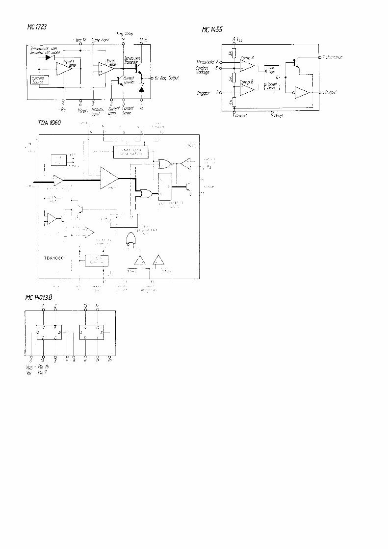
IC201 Integrated circuit Siemens TDA471SA IC202 Integrated circuit Motorola MC 17 23CPIC203 Integrated circuit Motorola MC 17 23 CP IC204a Integrated circuit National 1/2 LM358N IC204b Integrated circuit National 1/2 LM358N IC205 Integrated circuit Motorola MC1723CP IC206 Voltage regulator 8V Motorola MC78LOSACP
OC201 Opto coupler Siemens CNY 17-2

PU I and PU II unit N1407 (200) 3/5 Symbol Description Manufact. R201 Resistor 470 ohm +/-5% 2.5W Philips 2322 192 34701 R202 Resistor 2.2 Kohm +/-5% 0.33W Philips 2322 211 13222 R203 Resistor 2.2 Kohm +/-5% 0.33W Philips 2322 211 13222 R204 Resistor 18 Kohm +/-5% 0.33W Philips 2322 211 13183 R205 Resistor 1.8 Kohm +/-5% 0.33W Philips 2322 211 13182 R206 Resistor 1.5 Kohm +/-5% O.33W Philips 2322 211 13152 R207 Resistor 1.5 Mohm +/-5% 0.33W Philips 2322 181 53155 R208 Resistor 6.8 Kohm +/-5% 0.33W Philips 2322 211 13682 R209 Resistor 1.5 Kohm +/-5% 1.6W Philips 2322 191 31502 R210 Resistor 0.22 ohm +/-10% 4W Philips 2322 329 34227 R211 Resistor 0.22 ohm +/-10% 4W Philips 2322 329 34227 R212 Resistor 1.5 Kohm +/-5% 1.6W Philips 2322 191 31502 R213 Resistor 100 ohm +/-5% 0.33W Philips 2322 211 13101 R214 Resistor 100 ohm +/-5% 0.33W Philips 2322 211 13101 R215 Resistor 8.2 Kohm +/-5% 0.33W Philips 2322 211 13822 R216 Resistor l Kohm +/-5% 0.33W Philips 2322 211 13102 R217 Resistor 1.5 Kohm +/-5% 0.5W Philips 2322 212 13152 R218 Resistor 1.5 Kohm +/-5% 0.5W Philips 2322 212 13152 R219 Resistor 1 Kohm +/-5% 0.33W Philips 2322 211 13102 R220 Resistor l Kohm +/-5% 0.33W Philips 2322 211 13102 R221 Resistor 150 ohm +/-5% 0.33W Philips 2322 211 13151 R222 Resistor 1.5 Kohm +/-5% 0.33W Philips 2322 211 13152 R223 Resistor 2.7 Kohm +/-5% 0.33W Philips 2322 211 13272 R224 Resistor 27 ohm +/-5% 2.5W Philips 2322 192 32709 R225 Resistor 100 ohm +/-5% 2.5W Philips 2322 192 31001 R226 Resistor 560 ohm +/-5% 0.33W Philips 2322 211 13561 R227 Resistor 1 Mohm +/-5% 0.33W Philips 2322 211 13105 R228 Resistor 56 ohm +/-5% 0.33W Philips 2322 211 13569 R229 Resistor 4.7 Kohm +/-5% 0.33W Philips 2322 211 13472 R230 Resistor 2.7 Kohm +/-5% 0.33W Philips 2322 211 13272 R231 Resistor 0.11 ohm +/-10% 5W Philips 2322 329 35117 R232 Resistor 0.11 ohm +/-10% 5W Philips 2322 329 35117 R233 Resistor 0.11 ohm +/-10% 5W Philips 2322 329 35117 R234 Resistor 1 Kohm +/-5% 0.33W Philips 2322 211 13102 R235 Resistor 680 ohm +/-5% 0.33W Philips 2322 211 13681 R236 Resistor 8.2 Kohm +/-5% 0.33W Philips 2322 211 13822 R237 Resistor 2.7 Kohm +/-5% 0.33W Philips 2322 211 13272 R238 Pre.Set.Potentiometer 1 Kohm +/-10% Noble TM8 KV2-1S-1K-l0% R239 Resistor 560 Kohm +/-5% 0.33W Philips 2322 211 13561 R240 Resistor 3.3 Kohm +/-5% 0.33W Philips 2322 211 13332 R241 Pre.Set.Potentiometer 10 Kohm +/-20% Noble TM8 KV2-1S-10K R242 Resistor 2.7 Kohm +/-5% 0.33W Philips 2322 211 13272 R243 Pre.set.Potentiometer l0 Kohm +/-20% Noble TM8 KV2-13-10KR244 Resistor 4.7 Kohm +/-5% 0.33W Philips 2322 211 13472 R245 Resistor 220 ohm +/-5% 0.33W Philips 2322 211 13221 R246 Resistor 56 Kohm +/-5% 0.33W Philips 2322 211 13563 R247 Resistor 56 Kohm +/-5% 0.33W Philips 2322 211 13563 R248 Resistor 2.2 Kohm +/-5% 0.33W Philips 2322 211 13222 R249 Resistor 18 Kohm +/-5% 0.33W Philips 2322 211 13183 R250 Resistor 560 Kohm +/-5% 0.33W Philips 2322 211 13564 R251 Resistor 15 Kohm +/-5% 0.33W Philips 2322 211 13153 R252 Resistor 18 Kohm +/-5% 0.33W Philips 2322 211 13183 R253 Resistor 2.2 Kohm +/-5% 0.33W Philips 2322 211 13222 R254 Resistor 390 ohm +/-5% 0.33W Philips 2322 211 13391 R255 Resistor 22 ohm +/-5% 0.33W Philips 2322 211 13229 R256 Resistor 1 Kohm +/-5% 0.33W Philips 2322 211 13102 R257 Resistor 1.5 Kohm +/-5% 0.33W Philips 2322 211 13152 R258 Resistor 2.7 Kohm +/-5% 0.33W Philips 2322 211 13272 R259 Pre.Set.Potentiometer 22 Kohm +/-20% Noble TM8 KV2-13-22K R260 Resistor 56 ohm +/-5% 0.5W Philips 2322 212 13569

PU I and PU II unit N1407 (200) 4/5
Symbol Description Manufact. R261 Resistor 680 ohm +/-5% 0.33W Philips 2322 211 13681 R262 Resistor 1Mohm +/-5% 0.33W Philips 2322 211 13105 R263 Resistor 8.2Kohm +/-5% 0.33W Philips 2322 211 13822 R264 Resistor 100kohm +/-5% 0.33W Philips 2322 211 13104 R265 Resistor 15Kohm +/-5% 0.33W Philips 2322 211 13153 R266 Resistor 51Kohm +/-5% 0.33W Philips 2322 211 13513 R267 Resistor 1Kohm +/-5% 0.33W Philips 2322 211 13102 R268 Resistor 0.11ohm +/-10% 5W Philips 2322 329 35117 R269 Resistor 470 ohm +/-5% 0.33W Philips 2322 211 13471 R270 Resistor 3.9Kohm +/-5% 0.33W Philips 2322 211 13392 R271 Pre.set.Potentiometer 1Kohm +/-10% Noble TM8 KV2-1S-1K-10% R272 Resistor 620 ohm +/-5% 0.33W Philips 2322 211 13621 R273 Resistor 68Kohm +/-5% 0.33W Philips 2322 211 13683
RE201 Relay PASI KS/U-BV998 RE202 Relay PASI KS/U-BV998RE203 Relay PASI KS/U-BV998 RE204 Relay PASI KS/U-BV998 RE205 Relay PASI KS/U-BV998
T201 Transistor Philips BD650 T202 Transistor Philips BD650 T203 Transistor Motorola BDX34B T204 Transistor Philips BD138 T205 Transistor Philips BC640 T206 Transistor Philips BC639 T207 Transistor Philips BC338 T208 Transistor Motorola BDX34B
TR201 Transformer Tradania TD3435 TR202 Transformer Tradania TD4265 TR203 Transformer Tradania TD4265

Blower converter N 1407 (300) 1/2
Symbol Description Manufact. C301 Capacitor, polyester 100 nF +/-10% 100V Siemens B32510-Dl104-K C302 Capacitor, polyester 47 uF +/-20% 25V ROE EK1 00 BB 247E C303 Capacitor, polyester 220 nF +/- 5% 63V ERO MKT 1818 422 064 C304 Capacitor, polyester 10 nF +/-1O% 400V Siemens B32510-D6103-K C305 Capacitor, polyester 10 nF +/-1O% 400V Siemens B32510-D6103-K C306 Capacitor, polyester 220 nF +/- 5% 63V ERO MKT 1818 422 064 C307 Capacitor, polyester 10 nF +/-10% 400V Siemens B32510-D6103-K
1C301 Integrated circuit Motorola MC1455 P1 1C302 Integrated circuit Motorola MC14013 BCP 1C303 Integrated circuit Motorola MC1455 P1
D301 Diode, zener- 12V +/- 5% 2.5W Motorola MZP4742A D302 Diode Motorola lN4148 D303 Diode Motorola lN4148 D304 Diode Motorola lN4148 D305 Diode Motorola lN4148 D306 Diode Philips BAV21
OC301 Opto coupler Siemens CNY 17-2
R301 Resistor 33 Kohm +/-5% 0.33W Philips 2322 211 13333 R302 Resistor 10 Kohm +/-5% 0.33W Philips 2322 211 13103 R303 Resistor 33 Kohm +/-5% 0.33W Philips 2322 211 13333 R304 Resistor 1.5 Kohm +/-5% 0.5W Philips 2322 212 13152 R305 Pre.Set. Potentiometer 22 Kohm +/-10% Noble TM8 KV2-1S-22K-l0% R306 Resistor 33 Kohm +/-5% 0.33W Philips 2322 211 13333 R307 Resistor 5.6 Kohm +/-5% 0.33W Philips 2322 211 13562 R308 Resistor 100 Kohm +/-5% 0.33W Philips 2322 211 13104 R309 Resistor 1.5 Kohm +/-5% 0.33W Philips 2322 211 13152 R310 Resistor 10 Kohm +/-5% 0.33W Philips 2322 211 13103 H311 Pre.Set.Potentiometer 22 Kohm +/-10% Noble TM8 KV2-1S-22K-l0% R312 Resistor 18 Kohm +/-5% 0.33W Philips 2322 211 13183 R313 Resistor 1 Kohm +/-5% 0.33W Philips 2322 211 13102 R314 Resistor 3.3 Kohm +/-5% 0.33W Philips 2322 211 13332 R315 Resistor 8.2 Kohm +/-5% 0.33W Philips 2322 211 13822 R316 Resistor 470 Kohm +/-5% 0.33W Philips 2322 211 13474 R317 Resistor 8.2 Kohm +/-5% 0.33W Philips 2322 211 13822 R318 Resistor 470 Kohm +/-5% 0.33W Philips 2322 211 13474 R319 Resistor 1 Kohm +/-5% 0.33W Philips 2322 211 13102 R320 Resistor 470 ohm +/-5% 1.6W Philips 2322 191 34701 R321 Resistor 1 Kohm +/-5% 0.33W Philips 2322 211 13102 R322 Resistor 330 ohm +/-5% 2.5W Philips 2322 192 33301 R323 Resistor 1 Kohm +/-5% 0.33W Philips 2322 211 13102 R324 Resistor 470 ohm +/-5% 1.6W Philips 2322 191 34701 R325 Resistor 1 Kohm +/-5% 0.33W Philips 2322 211 13102
T301 Transistor Philips BC338 T302 Transistor Philips BC3J8 T303 Transistor Philips BC548 T304 Transistor Motorola MPS-AO6 T305 Transistor Motorola MPS-AO6

Input filter and fuses N1407 (400) 1/1
Symbol Description Manufact.
C401 Capacitor, polyester 2.2uF +/-10% 100V Siemens B32512-E1225-K C402 Capacitor, polyester 2.2uF +/-10% 100V Siemens B32512-E1225-K C403 Capacitor, polyester 2.2uF +/-10% 100V Siemens B32512-E 1225-K C404 Capacitor, polyester 2.2uF +/-10% 100V Siemens B32512-E1225-K C405 Capacitor, polyester 2.2uF +/-10% 100V Siemens B32512-E1225-K C406 Capacitor, polyester 2.2uF +/-10% 100V Siemens B32512-E1225-K C407 Capacitor, polyester 1uF +/-20% 100V ERO MKT 1822-510-016 C408 Capacitor, polyester 1uF +/-20% 100V ERO MKT 1822-510-016 C409 Capacitor, electrolytic 2200uF -10/+50% 40V ROE EG 00 MG 422G C410 Capacitor, electrolytic 2200uF -10/+50% 40V ROE EG 00 MG 422G
D40l Diode Motorola MR750 D402 Diode Motorola MR750
F401 Fuse 10A 3.6 x 32mm Wickmann 311010 F402 Fuse 35A 3.6 x 32mm Wickmann 311035
L401 Coil S. P. TL354
24V POWER SUPPLY + T1130 N1407 (500) 1/1
Symbol Description Manufact.
C501 Capacitor, polycarbonate 470 nF +/-10% 250V ERO MKC 1860-447-255 C502 Capacitor, polycarbonate 470 nF +/-10% 250V ERO MKC 1860-447-255 C502 Capacitor, electrolytic 4700 uF -10/+30% 40V FRAKO EBA 4700-40 isol C504 Capacitor, polycarbonate 470 nF +/-10% 250V ERO MKC 1860-447-255
D501 Diode bridge G.I. KBPC6T 005 D502 Diode bridge G.I. KBPC6T 005 D503 Diode, zener 75V :5% 5W Motorola lN5374B D504 Diode, zener 75V :5% 5W Motorola lN5347B D505 Diode, bridge Matorola BYW61
L501 Choke Tradania TD4573 L502 Choke Tradania TD4573 L503 Choke Tradania TD4240 L504 Choke Tradania TD4573 LSOS Choke S. P . TL383
R501 Resistor 220 ohm : 10% 10W ARCOL HS10, 220, 10% R502 Resistor 2.7 ohm : 5% 2.5W Philips 2322 192 32708 R503 Resistor 2.7 ohm : 5% 2.5W Philips 2322 192 32708 R504 Resistor 2.7 ohm : 5% 2.5W Philips 2322 192 32708 R505 Resistor, varistor S14K50 Siemens Q69-X3135
T501 Transistor (Matched pair) Motorola MJ802T502 Transistor (Matched pair) Motorola MJ802 T503 Transistor Motorola BD808 T504 Transistor (Matched pair) Sescossem BUV19T505 Transistor (Matched pair) Sescossem BUV19 T506 Transistor Philips BD650 T507 Transistor Philips BD649 T508 Transistor Philips BD650 T509 Transistor Philips BD649
TB501 Thermostat ON 55 +/-4ºC Elmwood 22455R-21-923 OFF 40 +/-4ºC
TR501 Transformer Tradania TD335 TR502 Transformer Tradania TD324
