jetageworld.com · web viewsingle stage. air compressor . operators manual . model no. 25s / 50s...
TRANSCRIPT
SINGLE STAGEAIR COMPRESSOR
OPERATORS MANUAL
Model No. 25S / 50S / 100S1
INSTRUCTION MANUAL & PART LIST
JETAGE GARAGE EQUIPMENTSHead Office: B-74, IInd Floor, Phase – II Naraina Industrial Area, New Delhi – 110028 (INDIA)
Telephone: +91-11-25897389, 25897528 Fax: +91-11-25897485 Mobile: +91-9810292921, 9212743900 Email: [email protected] Service Email:[email protected] Website: www.jetageworld.com a Service Helpline No: +91-1125844166, 9212743920, 9212743903
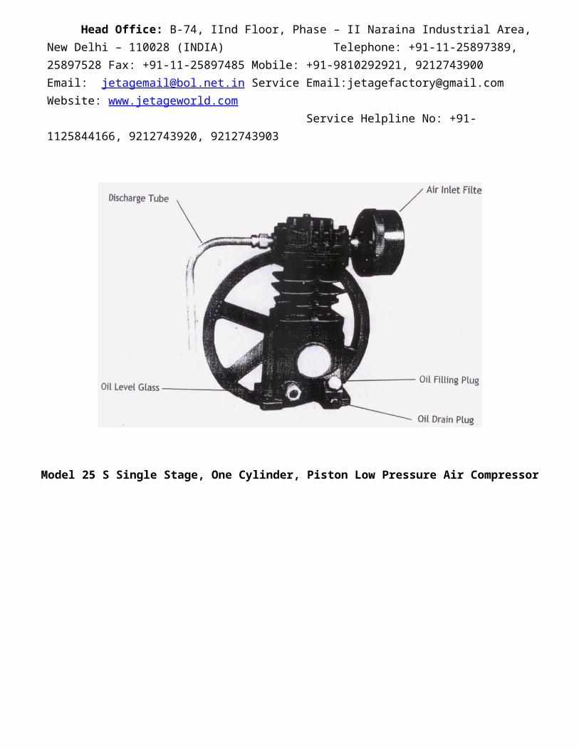
Model 25 S Single Stage, One Cylinder, Piston Low Pressure Air Compressor
Model 50 S Single Stage, One Cylinder, Tow Piston Low Pressure Air Compressor

Model 100 S1 Single Stage, One Cylinder, Two Piston Low Pressure Air Compressor

WARNING
Never inhale directly the compressed air produced by this air compressor. Always disconnect power supply before perfoming any maintenance or repair work. Do not operate the air compressor in any areas where explosive or flammable vapors or liquids may exit. Over pressurizing the air receiver, or using a receiver, which does not meet the design, Limits for the
compressor can cause the air receiver to rupture or explode and which result in the severe injury or death.
Changes to the air receiver’s structure or an internal rusting in it will cause the air receiver to repute or explode and result in severe injury or death.
The air receiver is equipped with safety valve to protect aginst over – pressurization.DO NOT REMOVE, ADJUST OR MAKE SUBSTITUIONS FOR THE SAFETY VALVE. Periodically pull the ring on the safety valve to ensure operates freely. If the valve is stuck or does not operate freely it must be replaced.
Never drill into , weld to, or alter the air receiver daily or before each use.
Drain water / condensate from the air receiver daily or before each use.
DO NOT ATTEMPT TO ADJUST, REMOVE OR BYPASS THE PRESSURE SWITHCH, OR CHANGE OR MODIFY ANY PRESSURE CONTROL RELATED DEVICE.
Never point air nozzle of sprayer towards any part of the body, or towards any another person. Never operate the compressor with the beltguard assembly, removed, damaged or broken.
SAFETY PRECAUTIONS
A safety valve must be installed in the discharge piping between the compressor and any possible restriction such as a block valve, after cooler, or air dryer failure to installed a safety valve could result in over pressure, pipe rupture damaged to the compressor and personal injury.

SECTION – 1
GENERAL DESCRIPTION
Application : Single or Two stage, single-acting, air cooled compressor that do not require installation on a special foundation. All models can be furnished as compact, self contained, receiver-mounted units driven by an electric motor or gasoline engine. The units are also sold as bare, or base plate – mounted compressors.
These compressors may be used for compressed airs application requiring air from 10 to 250si (0.703 to 17.5kg/cm2) with delivery for 5.0 to 45.9 CFM (0.141 to 1.299 m3 / min.)
Application of these compressor in industrial plants, service station and auto repair shops. Supplementary service includes such uses as standby service for air when larger compressor are shutdown.
Basic principal : On the suction stroke of the individual piston, air at atmospheric pressure enters the cylinder through the inlet filter and the valve located in each airhead. On the compression stroke of each piston, air is forced out through the valve and passes into a common discharge manifold (on two cylinder compressors) form where it is piped to the receiver of system.
START-UP RECOMMENDATIONS
COMPRESSOR LUBRICATION
Fill crankcase to proper level bottom thread of oil filler opening. Tighten oil plug HAND TIGHY ONLY.
After the initial four hours of operation at full load oil is to be drained whit it is hot and the frame refilled with new oil
Check compressor rotation by flicking “ START-STOP” switch. Rotation is shown by arrow on fly wheel. If rotation is incorrect, interchange two of three leads on three phase motors.

TO CHECK OPERATION
Close service valve and start compressor
NOTE : If equipped with (OPTIONAL) Water Cooled After cooler, urn on cooling water flow.
Start the compressor and allow the receiver (tank) to build up to pressure for which you ordered the machine. At this pressure, If the unit is equipped with Automatic Start and Stop regulation, the pressure switch shold cause the unit to stop. If the unit is equipped with constant speed control, It should unload (run without compressing air), Run for about ten minutes by bleeding air from receiver to let unit warm up and observe for excess vibration, unusual noise. NOTE : If the units does not operate properly, shut down immedeately, and call local ZEN AIR Distributors OR From Marketing Office.
1. Open Service valve and / or drain valve to let pressure in receiver drop. Note the pressure at witch compressor starts or reloads.
2. Pull ring on all safety valves to be sure they relieve and rest. Do this several times. 3. Adjust pressure switch on Automatic Start and Stop or Auxiliary Valve Constant Speed Control, if
necessary, (If any adjustment are necessary, see manufacture’s instruction book)4. Check tightness of all bolts and fittings. As given below.
AIR-COLLED AFTER COLLER : The cooler consists of finned tubing through which compressed air passes on its way to the air receiver cooling air drawn over these tubes by the fan-type flywheel cools the compressed air and condenses moisture. This moisture passes on to the receiver and is drained either manually or by an automatic drain trap.
WATER-COOLED AFTER COOLER : Standard water-cooled after cooler consists of multiple copper tubes through which air passes. Cold water passes through shell in reverse direction for better heat transfer.

DISCHARGE PIPING
The following general instruction cover only the installations cover only the installation of discharge piping and placement of the pressure switch and safety valve is system using a detached receiver. Discharge piping should be the same size as the compressor discharge connection. All pipe and fitting must be certified safe for the pressure involved. Pipe thread lubricant is to be used on all threads, and all joints are to be made up tightly, since small leaks in the discharge systems are the largest single cause of high operation cost. If your compressor u\runs more than you believe it should, the most likely cause is a likely cause pipeline, and leaks are easily located by squirting soap and water solution around all joints and watching for bubbles.
Where a sub-base mounted unit or a bare compressor is supplied, it is very important to observe the following points when installing the piping between the compressor and the receiver.
Install check valve as close to the receiver as possible. DO NOT INSTALL IN COMPRESSOR CYLINDER DISCHARGE HOLE. CHECK FOR PROPER AIR FLOW DIRECTION.
If possible, run the piping down from the compressor discharge to permit condensate to drain into the receiver. If this is not possible, Install a “drain leg” should project down from the compressor discharge and be at least 10” long (254mm). Put a drain valve at the end of this and drain at least weekly or as offer as necessary.
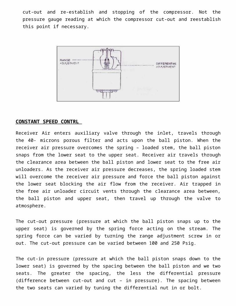
CONSTANT SPEED CONTROL
Constant Speed Control requires auxiliary valve. Clean valve regularly to prevent it from clogging.
AUTOMATIC START STOP CONTROL
Automatic Start Stop Control is obtained by means of a pressure switch which makes and breaks an electrical circuit, starting and stopping the driving motor, there by maintaining the air receiver pressure within definite times. The pressure switch is piped to the receiver and is actuated by changes in air receiver pressure.
NOTE : With automatic start and stop control motor must be limited to six (6) start per hour, otherwise unit must be operated at constant speed control.

PRESSURE SWITCH ADJUSTMENT
The pressure switch has a range adjustment and a differential adjustment. The cut – out (Compressor Shutdown) is the pressure at switch contacts close.
Screwing the range adjustment clockwise may increase the cut-out point. Screwing the range adjustment counter clockwise decreases the cut-out point. Note the pressure gauge reading at which compressor cut-in and cut-out and re-establish and stopping of the compressor. Not the pressure gauge reading at which the compressor cut-out and reestablish this point if necessary.
CONSTANT SPEED CONTRL
Receiver Air enters auxiliary valve through the inlet, travels through the 40- microns porous filter and acts upon the ball piston. When the receiver air pressure overcomes the spring – loaded stem, the ball piston snaps from the lower seat to the upper seat. Receiver air travels through the clearance area between the ball piston and lower seat to the free air unloaders. As the receiver air pressure decreases, the spring loaded stem will overcome the receiver air pressure and force the ball piston against the lower seat blocking the air flow from the receiver. Air trapped in the free air unloader circuit vents through the clearance area between, the ball piston and upper seat, then travel up through the valve to atmosphere.
The cut-out pressure (pressure at which the ball piston snaps up to the upper seat) is governed by the spring force acting on the stream. The spring force can be varied by turning the range adjustment screw in or out. The cut-out pressure can be varied between 100 and 250 Psig.
The cut-in pressure (pressure at which the ball piston snaps down to the lower seat) is governed by the spacing between the ball piston and we two seats. The greater the spacing, the less the differential pressure (difference between cut-out and cut – in pressure). The spacing between the two seats can varied by tuning the differential nut in or bolt.

To adjust the cut-out pressure, loosen the range lock – nut and turn the range adjustment screw clockwise for lower pressure. (1/8 turn creats a 12 Psig change in cut – out pressure.) Retighten the range lock-nut after adjusting the cutout pressure.
NOTE : The differential pressure will the change in cut-out pressure.
Auxiliary valve designed for dual control operation include a constant speed lockout cap screw. For constant speed operation, loosen the wing – nut, turn the cap screw clockwise until it contacts the springs guide, then turn the cap screw counter clock wise one full turn and tighten the wing-nut For start & stop operation loosen the wing-nut turn the cap screw c lockwise until it contacts the spring guide, then the cp screw lucks wise one additional turn and tighten the wing-nut. This action cut-out setting
NOTE : For proper dual control operation, the cut-out pressure above the must be at least 5 Psig greater than the cut-out the cut-out pressure of the auxiliary valve.

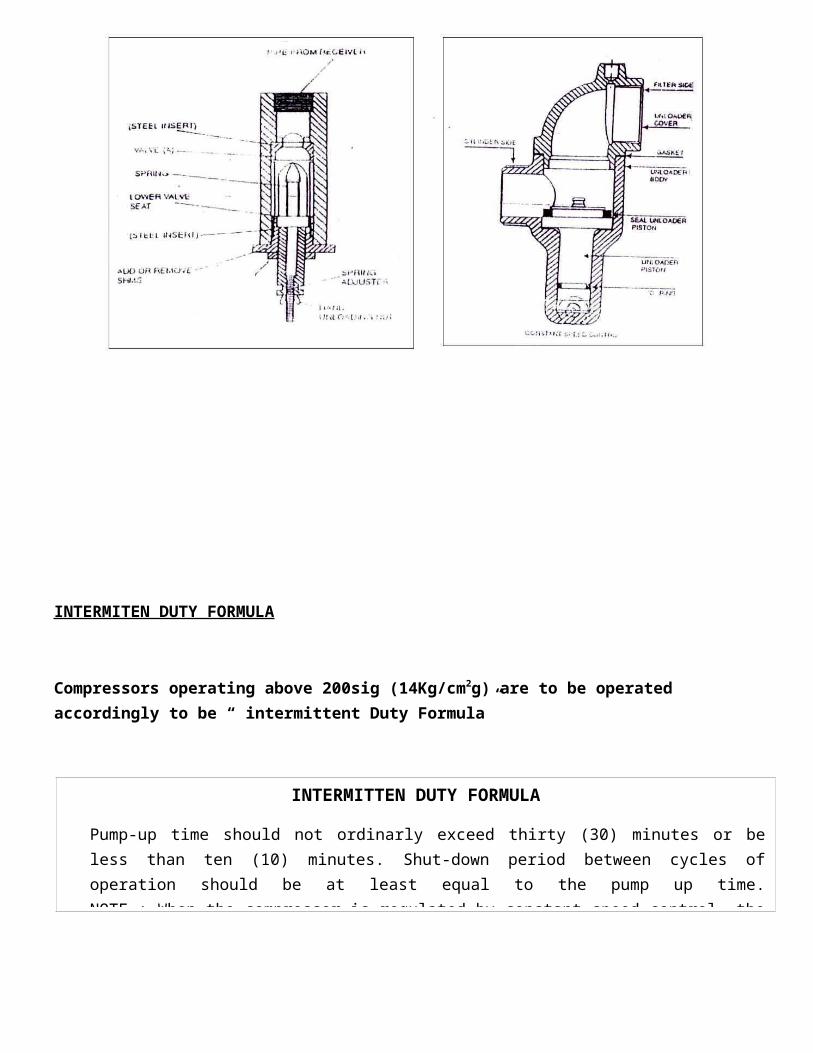
INTERMITEN DUTY FORMULA
Compressors operating above 200sig (14Kg/cm2g) are to be operated accordingly to be “ intermittent Duty Formula”
A pump-up time limit with the following cool-down period is recommended to protect the valves and heads against stabilized high operating temperatures, which could rapidly build up carbon in three areas.
OPERATION
To obtain optimum performance at minimum cost, observe the “Maintenance” guide as under.
MAINTENANCE
INTERMITTEN DUTY FORMULA
Pump-up time should not ordinarly exceed thirty (30) minutes or be less than ten (10) minutes. Shut-down period between cycles of operation should be at least equal to the pump up time. NOTE : When the compressor is regulated by constant speed control, the shut-down period is the time the compressor is operating unloaded.
WARNING
BEFORE ATTEMPTING ANY REPAIR WORK ON THE UNIT, BE CERTAIN THE ISOLATION SWITCH IS LOCKED IN THE “OFF” POSIION, OR THE WIRING IS DISCONNECTED FROM THE LINE COMPLETE ELECTRICAL ISOLATION IS NOT ACCOMPLISHED BY HAVING THE MOTOR STARTER IN THE “OFF POSITION, THE CONTROL CIRCUIT MAY STILL BE “HOT” BLOW DOWN THE PRESSURE FROM THE RECEIVER ISOLATE THE UNIT FROM ANY OUTSIDE SOURCE OF AIR PRESSURE. THESE SIMPLE PRECAUION WILL PREVENT ACCIDENT
MAONTANNCE OPERATION
SERVICE INTERVAL Operating Hours/Mouths – which comes first
500/3 1000/6 1500/9 2000/12 2500/15COMPRESSOR
Air Inlet Filter – Inspect & Clean Weekly Frame Oil Level – Check Daily Inspected Oil for contamination – Change if necessary Monthly
Frame Oil – Change Petroleum lube X X X X XKeyston or Anderol 500 every 1500 hours or 13 months whichever is first
Compressor Valves – Inspected and Clean X X X X XIntercooler – Clean Exterior Weekly Low Oil Level Switch – Check Operation X X X X XOperator Safety Valve – Manually Weekly Clean Cylinder Cooling Fins Weekly
V-BELT DRIVE Belt Tension – Check Monthly
MOTORMotor Bearings – Check & Lubricate XClean Monthly – (Weekly in Dusty Locations)
AFTERCOOLER Air cooled – Clean externally Monthly – (Weekly in Dusty Locations)Clean Air Flow Internally X XWater cooled – Check Discharge Water Temp. 120°F max
X X
Check Water Flow Rate AIR RECEIVER
Drain Condensate – Manual Operate Safety Valve
GENERAL Tighten or check all bolts Monthly Check for Unusual Noise and Vibration Daily Inspect for Air Leaks Monthly
COMPRESSOR LUBRICATION
Oil Level indictor glass is fitted at the bottom of the crank case cover. The line of level is indication by two lines. The upper line of the oil level glass is the upper level OR maximum oil should be maintained. In no case it should be less than lower line or minimum oil level. The level of oil should be checked every day & if required it should be filled up by adding more oil. Model Oil (Litres)
25 S 0.20050 S 0.400
100 S1 1.800

LUBRICATING OIL RECOMMENDATIONS
The viscosity should be selected for temperature immediately surrounding the unit when it is in operation.
OIL VISCOSITY TABLE
Temp. Range Viscosity at 100°F (37.8°C)SSU Centistroke
40°F & Below (4.4°C & Below) 150 3240°F to 80° (4.4°C to 26.7°C) 500 11080°F & to 125°F (26.7°C to 51.7°C) 750 165
The viscosities given is the table are intended as a general guide only. Heavy –duty operation conditions require heavier viscosities. And where borderline temperature conditions are encountered the viscosity index of the oil should be considered. Always refer your specific operating conditions to your industrial lubricant supplier for recommendations.
AIR INLET FILTER
It is very important that the air inlet element must kept clean at all time. A dirty inlet filter reduces the capacity of the compressor.
The filtering element should be taken out atleast once a month and cleaned. As the dirt collects on the outside, the outside surfaces Should be brushed. The standard inlet air filter suitable only for normal industrial applications. Should be compressor be locked in an area where the atmosphere contains a heavy concentration of dust and dirt, an air cleaner utilizing a specially designed, high capacity element should be used.
BRETHER TUBE OR BREATHER VALVE
The breather tube or plug connects the interior of the frame.
SAFETY VALVE
Safety valves are designed to protect against damage from over pressure. A safety valve is provided in the intercooler of all two-stage units. This valve is set to blow at approximately 60 Psig. If the valve blows, and continues to blow for more than a minute, the compressor should be stopped at
once. Refer to the trouble chart to determine the cause of the blowing safety valve. Units that are supplied mounted on a receiver will be furnished with a receiver safety valve.
This valve is set at the factory to blow off at the pressure rating of the air receiver or 10 to 20 Psig, above the compressor operating pressure.
If a hand valve is installed between the compressor and receiver, a safety valve must be installed between the compressor and hand valve.
WARNING DO NOT CHANGE THE BLOW-OFF PRESSURE OF A SAFETY VALVE DO NOT REMOVETHE SAFETY VALVE AND REPLACE IT WITH A PLUG, SINCE THIS WILL ELEMINATETHE PROTECTION PROVIDED AND MAY RESULT IN SERIOUS INJURY TO PESONNELAND DAMAGE TO THE COMPRESSOR AND RECIVER. SAFETY CODES REQUIRES ASAFETY VALVE TO PROTECT THE RECEIVER FROM OVER-PRESSURE.
CHECK VALVE
The check valve is located in the discharge line acts to check the flow of air receiver to the cylinder when the compressor is stopped.
AIR VALVE CLEANING
ZEN AIR stainless steel finger valves are quick acting, durable, reliable and easily serviced. Valves are readily accessible and may be removed without disturbing piping
To clean the valves, take out the air head cap screw and remove the head and valve plate from the cylinder. Remove the valves from the valve plate and clean both the valve and seat by, use a non – flammable safety Solvant to lossen dirt, oil or carbon deposit. Should it be necessary to scrape, do not lightly to prevent marring the valve or seating surface.
BELT INSTALLATION AND ADJUSTMENT
When installing new belts, do not try the belts over the groves. The proper method of removing an installing new belts is to loosen the anchore screw and the belt tightener screw. Push the motor toward the compressor. Use the tightener screw to adjust belt tension on the new belts.

It is important the belt be properly adjusted. A belt that is too loose will slip and cause heating and wear and a belt that is too tight may overload the bearings. A quick check to determine if belt adjustment is proper may be made by observing the slack side of the belt for a sight bow when the unit is in operation. If a slight bow is evident, belts are usually adjusted satisfactory. However, the recommended method of checking belt tension is by the more accurate spring scale measurement method that follows.
A. Measure the belt span. B. At the centre of the span (t), apply a force (perpendicular to the span, by attaching a spring scale to
the two outside belts. The force applied to the spring scale should be sufficient to deflect the belts 1/64” (0.396mm) for every inch of span length (t) For example : The deflection of 100” (250mm) span would be 100/ 64” or 25/16” (39.6mm), thus the force applied to the spring scale should deflect the belts to 25/16” (39.6mm).
C. When the belts are deflected, the necessary distance compare the spring scale reading (in Lbs. Force) with the value given in the table.
TORQUE VALVCE TABLE
NATIONAL COARSE GRADE2 GRADE5 GRADE8
Dia. Pitch 1/4" – 20 48 in. L.B. 5 Nm. 72 in. L.B. 8 Nm. 108 in. L.B. 12 Nm.
5/16” – 18 96 in. L.B. 11 Nm. 144 in. L.B. 16 Nm. 18 in. L.B. 24 Nm.3/8” – 16 15 Ft. L.B. 20 Nm. 23 Ft. L.B. 31 Nm. 31 Ft. L.B. 42 Nm.
7/16” – 14 24 Ft. L.B. 33 Nm. 36 Ft. L.B. 49 Nm. 51 Ft. L.B. 69 Nm.1/2” – 13 37 Ft. L.B. 50 Nm. 56 Ft. L.B. 76 Nm. 80 Ft. L.B. 108 Nm.
9/16” – 12 53 Ft. L.B. 72 Nm. 81 Ft. L.B. 110 Nm. 16 Ft. L.B. 157 Nm.5/8” – 11 68 Ft. L.B. 92 Nm. 113 Ft. L.B. 153 Nm. 160 Ft. L.B. 217 Nm.3/4” – 10 131 Ft. L.B. 177 Nm. 203 Ft. L.B. 275 Nm. 28 Ft. L.B. 388Nm.
We recommended the use of a torque wrench on alt bolts, cap screw, and nuts using the values in the following table. The values given are for thread lubricated with oil or grease. You determine the grade of bolt or cap screw being tightened, use the following information. Grade 2 : No markings or venor identification on the head Grade 5 : Letter “s” or 3 lines and/or vendor identification on the head. Grad 8 : Letter “V” or 6 lines and /or vendor identification on the head.

STANDARD BELT TENSIONBelt Type Normal Tension Normal Tension
A 11/4 Lbs. (0.565 kg) 17/8 Lbs. (0.85 kg)B 23/4 Lbs. (1.25 kg) 4 Lbs. (1.81 kg)C 51/2 Lbs. (2.5 kg) 81/4 Lbs. (3.74 kg)
If the reading between the value for normal tension and 150% normal tension, the belt tension should be satisfactory. A reading below the value form normal tension indicated the belt slack should be reduced, and conversely, a reading exceeding the value for 150% normal tension indicated the belt stack should be increased. Experienced has shown that a now drive can be tightened initially to two times normal tension to allow for any drop in tension during run in.