sciencedoctorschool.files.wordpress.com · web view4/2/2020 · earth – green and yellow...
TRANSCRIPT

ElectricitySeparate Physics
Electricity facts
Name ______________________________
Class ______________________________
Teacher ______________________________
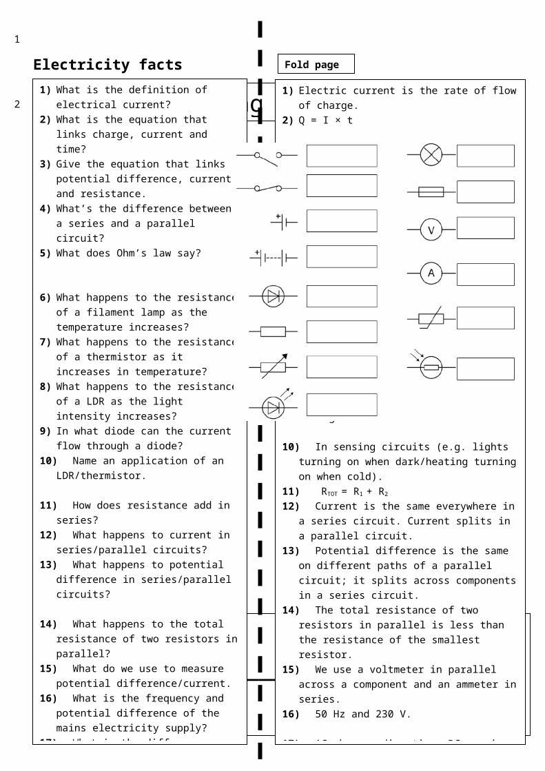
Drawing circuits1) Electric current is the rate of flow of charge. 2) Q = I × t
3) V = I × R
4) A series circuit has only one path for the current to flow; a parallel circuit has more than one.
5) The current through an ohmic conductor (at a constant temperature) is directly proportional to the potential difference across the resistor.
6) As the temperature increases, the resistance of a filament lamp also increases.
7) The resistance decreases as the temperature increases.
8) The resistance decreases as the light intensity increases.
9) Current can only flow one way through a diode.
10) In sensing circuits (e.g. lights turning on when dark/heating turning on when cold).
11) RTOT = R1 + R2 12) Current is the same everywhere in a series circuit.
Current splits in a parallel circuit. 13) Potential difference is the same on different paths of
a parallel circuit; it splits across components in a series circuit.
14) The total resistance of two resistors in parallel is less than the resistance of the smallest resistor.
15) We use a voltmeter in parallel across a component and an ammeter in series.
16) 50 Hz and 230 V.
17) AC changes direction, DC remains in same direction. 18) Live – brown. Neutral – blue. Earth – Green and
yellow stripes. 19) Live wire carries the AC, neutral wire completes the
circuit, earth wire is a safety wire. 20) The fuse melts, making the circuit incomplete and
stops current from flowing. 21) P = I × V P = I2 × R22) E = P × t E = Q × V23) A network of cables and transformers linking power
stations to consumers. 24) It increases the potential difference, but decreases
the current to reduce heat loss in cables. 25) It decreases the potential difference to a safe level
for consumers.
1) What is the definition of electrical current?2) What is the equation that links charge,
current and time?3) Give the equation that links potential
difference, current and resistance. 4) What’s the difference between a series and
a parallel circuit?5) What does Ohm’s law say?
6) What happens to the resistance of a filament lamp as the temperature increases?
7) What happens to the resistance of a thermistor as it increases in temperature?
8) What happens to the resistance of a LDR as the light intensity increases?
9) In what diode can the current flow through a diode?
10) Name an application of an LDR/thermistor.
11) How does resistance add in series?12) What happens to current in series/parallel
circuits?13) What happens to potential difference in
series/parallel circuits?
14) What happens to the total resistance of two resistors in parallel?
15) What do we use to measure potential difference/current.
16) What is the frequency and potential difference of the mains electricity supply?
17) What is the difference between AC and DC?18) What are the colours of the live, neutral and
earth wires?19) What do the live, neutral and earth wires
do?20) What happens to the fuse if the current is
too high?21) Give two equations for electrical power. 22) Give two equations for energy transfer. (23) What is the national grid?
24) What does a step-up transformer do?
25) What does a step-down transformer do?
Fold page here
1
2

We use circuit symbols to show different components (parts) of an electrical circuit. Circuit diagrams are drawn in pencil and a ruler used to draw the connecting wires.
For the circuit to work, it needs to be complete (not have any gaps in it)
Fill out the picture opposite with the names of the different components.
There are two types of circuit, series and parallel.
In a series circuit:
-There is only one route around the circuit.
-The current needs to flow through all of the components.
In a parallel circuit:
-There is more than one route around the circuit.
-The current does not need to flow through all of the components.
Basic:
1. Draw the symbols for:a) A bulbb) A cellc) A batteryd) A voltmetere) An ammeterf) A fuseg) An LDR
1
2
3
4
5
6
7
8
9
10
11
12
13
14
15
16
17
18

h) A thermistori) A resistorj) A variable resistork) An LEDl) A switch
2. Look at each of the circuit diagrams to the right. Label each one as either a series or parallel circuit. If the circuit is parallel, write how many different routes there are around the circuit.
Medium:
1) Draw a series circuit with two cells, a bulb and an ammeter.
2) Draw a series circuit with a cell an open switch and a motor.
3) Draw a series circuit with a cell, a closed switch, a motor and a bulb.
4) Draw a circuit with two cells, and three bulbs in parallel with the cells.

5) Draw a circuit with one cell, and with a bulb and voltmeter in parallel with each other.
Parts of a circuit will only work if there is a complete circuit for the current to flow. If there is a break in the circuit then it’s not complete.
Current also prefers to take the path of least resistance.
Hard:
1) Bulb A is unscrewed. Which bulbs are on and which bulbs are off? Explain why.
2) Bulb D is unscrewed. Which bulbs are on and which bulbs are off? Explain why.
3) Bulb E is unscrewed. Which bulbs are on and which bulbs are off? Explain why.
4) Would bulb 2 be lit when the switch is open? Explain why.
5) Would bulb 1 be lit when the switch is open? Explain why.
6) Would bulb 1 be lit when the switch is closed? Explain why.
Series Circuits
1. Make the circuit below. Which bulbs are on?____________________________________
3. Now put a wire across each side of bulb B. Which bulbs are on? Why?____________________________________
A B

(a)
Use words from the box to label the components, A, B, and C, in the circuit diagram.
The drawing shows the circuit used to investigate how the current through a 5 ohm (Ω) resistor changes as the potential difference (voltage) across the resistor changes.
2. Now put a wire across each side of bulb A. Which bulbs are on? Why?____________________________________
3. Now put a wire across each side of bulb B. Which bulbs are on? Why?____________________________________
4. Make the circuit below. Which bulbs are on?____________________________________
Parallel Circuits
5. Now put a wire across each side of bulb A. Which bulbs are on? Why?____________________________________
6. Now put a wire across each side of bulb B. Which bulbs are on? Why?____________________________________
A A
A
A A
B B
B
B Bcell diode lamp resistor switch
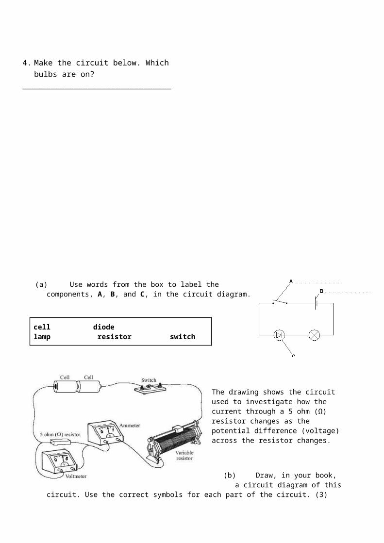
(b) Draw, in your book, a circuit diagram of this circuit. Use the correct symbols for each part of the circuit. (3)
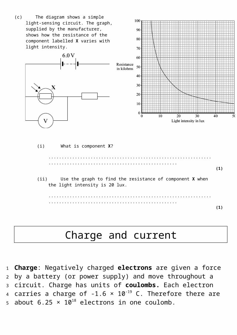
(c) The diagram shows a simple light-sensing circuit. The graph, supplied by the manufacturer, shows how the resistance of the component labelled X varies with light intensity.
(i) What is component X?
...............................................................................................................(1)
(ii) Use the graph to find the resistance of component X when the light intensity is 20 lux.
...............................................................................................................(1)
Charge: Negatively charged electrons are given a force by a battery (or power supply) and move throughout a circuit. Charge has units of coulombs. Each electron carries a charge of -1.6 × 10⁻¹⁹ C. Therefore there are about 6.25 × 10¹⁸ electrons in one coulomb.
Current: The rate of flow of charge (i.e. how much charge is flowing every second). Current has units of Amps and is measured with an ammeter. The
Charge and current
1
2
3
4
5
6
ammeter measure the number of charges that flow through it in one second. They therefore must go in series.
Charge, current and time are linked by the equation:
Q = I × t
Where I = Current (Amps, A)
Q = Charge (Coulombs, C)
t = Time (s)
Example question: Calculate the current when 4 C of charge passes a point in 8 seconds.
Step 1: Write the equation. Rearrange if necessary. Q = I × t → Q ÷ t = IStep 2: Write down the variablesQ = 4 Ct = 8 sStep 3: Calculate the answerI = Q ÷ t = 4 ÷ 8 = 0.5 A
Basic: Find the unknown quantity – show your working in your books:
a) I =
Q = 8 C
t = 20 s
b) I =
Q = 240 C
t = 300 s
c) I =
Q = 400 C
t = 200 s
d) I =
Q = 750 C
t = 350 s
e) I =
Q = 300 C
t = 100 s
f) I =
Q = 50 C
t = 2 s
g) Re-arrange the equation for Q
h) I = 2.5 A
Q =
t = 300 s
i) I = 5 A
Q =
t = 200 s
j) I = 13 A
Q =
t = 350 s
k) I = 10 A
Q =
t = 100 s
l) I = 6 A
Q =
t = 2 s
1
2
3
4
5
6
7
8
9
10
11
12
13
14
15
16
17
18

m) Re-arrange the equation for t
n) I = 4 A
Q = 240 C
t =
o) I = 20 A
Q = 400 C
t =
p) I = 5 A
Q = 750 C
t =
q) I = 6 A
Q = 300 C
t =
r) I = 2.4 A
Q = 50 C
t =
Medium: Find the unknown quantity (CONVERT FIRST to SECONDS)
a) I =
Q = 140 C
t = 4 min = _______ s
b) I = 0.3 A
Q =
t = 1.5 hours = _______ s
c) I = 0.9 A
Q =
t = 3 min = _________ s
d) I =
Q = 200 C
t = 5 min = _______ s
e) I = 1.5 A
Q =
t = 2 hours = _______ s
f) I = 0.4 A
Q =
t = 7 min = _________ s
Hard: WORD PROBLEMS
1. How much current must there be in a circuit if 1000 coulombs flow past a point in the circuit in 4 minutes?
2. A circuit is switched on for half a minute and 90 coulombs of charge flowed. What was the current flowing through the circuit?
3. If there is a current of 10 mA in a circuit for 0.5 s, what quantity of electric charge flows in through the circuit?
4. How much time is required for 0.3 coulombs of charge to flow past a point if the rate of flow (current) is 2 mA?
5. During electrolysis 6A was passed through some copper chloride and a charge of 1.2 kC flowed. How long was the experiment on for?
6. A bed lamp is switched on for 10 minutes. It works on a current of 0.5 A. How much charge flowed?
Q1.The plug of an electrical appliance contains a fuse.
(a) What is the correct circuit symbol for a fuse?
Tick one box.

(1)
The diagram below shows the structure of a fuse.
(b) Write down the equation that links charge flow, current and time.
___________________________________________________________________(1)
(c) The fuse wire melts when 1.52 coulombs of charge flows through the fuse in 0.40 seconds.
Calculate the current at which the fuse wire melts.
___________________________________________________________________
___________________________________________________________________
___________________________________________________________________
___________________________________________________________________
Current = _______________________ A(3)
In a series circuit the current flow through one continuous path. This means that the current must be the same at all parts in a series circuit.
In the series circuit opposite, the current is 5 Amps in all positions.
Current in series and parallel
1
2
3
4
5
6

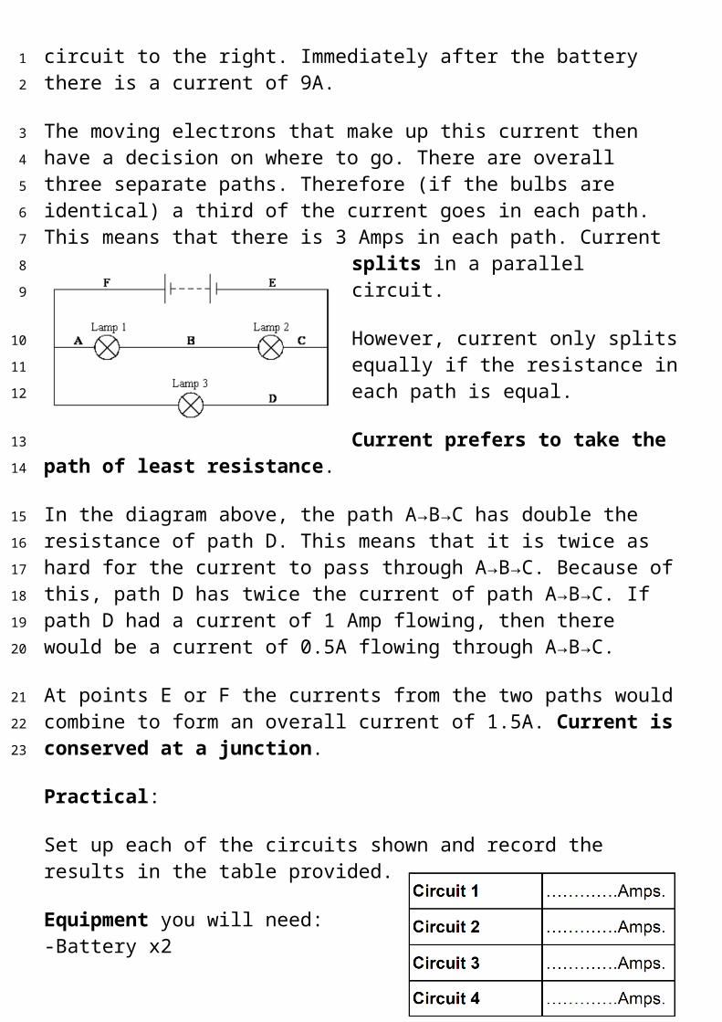
However, things are more complicated for a parallel circuit. Let’s take the circuit to the right. Immediately after the battery there is a current of 9A.
The moving electrons that make up this current then have a decision on where to go. There are overall three separate paths. Therefore (if the bulbs are identical) a third of the current goes in each path. This means that there is 3 Amps in each path. Current splits in a parallel circuit.
However, current only splits equally if the resistance in each path is equal.
Current prefers to take the path of least resistance.
In the diagram above, the path A→B→C has double the resistance of path D. This means that it is twice as hard for the current to pass through A→B→C. Because of this, path D has twice the current of path A→B→C. If path D had a current of 1 Amp flowing, then there would be a current of 0.5A flowing through A→B→C.
At points E or F the currents from the two paths would combine to form an overall current of 1.5A. Current is conserved at a junction.
Practical:
Set up each of the circuits shown and record the results in the table provided.
Equipment you will need:
-Battery x2-Bulb x2-Ammeter x1-Connecting wires x5
1
2
3
4
5
6
7
8
9
10
11
12
13
14
15
16
17
18
19
20
21
22
23

Conclusion: _______________________________________________________
_________________________________________________________________
_________________________________________________________________
Stretch: Unscrew one of the bulbs. What do you notice? Why does this happen?
_________________________________________________________________
_________________________________________________________________
Now build the following circuit:
Place an ammeter in positions 1, 2 and 3 and note the currents down below.
Current in position 1: ___________
Current in position 2: ___________
Current in position 3: ___________
Conclusion: _______________________________________________________
_________________________________________________________________
Stretch: Unscrew one of the bulbs. What do you notice? Why does this happen?
_________________________________________________________________
_________________________________________________________________
Task: Write the currents on the following ammeters
Basic:
123

Medium:
Hard:
1. The resistors in the circuit opposite are not of equal resistance. What is the current on the remaining ammeters? Explain why.
2. What is the current through resistor Y? Explain why.
3. The picture shows an electric cooker hob. The simplified circuit diagram shows how the four heating elements connect to the mains electricity
supply. The heating elements are identical.
At full power the hob draws a current of 26 A. What is the current through each heating element?
4.The diagram above shows how someone could
get an electric shock from accidentally cutting into an electric cable. If this happens, the fuse can overheat and melt. What is the current in the hedge trimmer above? Why?
1
2

5. What is the current in the ammeter in the diagram to the left? Why?
Potential difference is the difference in the amount of energy that charge carriers have between two points in a circuit. The following equation shows this:
E = Q × V
Where E is the energy (in Joules)
Q is the charge (in Coulombs)
V is the potential difference (in Volts)
If we rearrange this equation to give V = E ÷ Q, we can see where the definition of potential difference comes from.
Power is a measure of how quickly energy is transferred from one form to another. The following equation shows this:
P = E ÷ t
Where P is the power (in Watts)
E is the energy transferred (in Joules)
t is the time (in seconds)
Potential difference, power and energy
1
2
3
4
5
6
7
8
9
10
11
12
13
14
15
16
17
18
19
20

Note that you will commonly see the second equation in its rearranged form E = P × t.
Task: Complete in your exercise bookBASIC 1. Re-arrange the equations in order to find equations for:
a) time tb) power Pc) charge Qd) potential difference V
2. Calculate the energy transferred by a 3,000 W hairdryer in 60 seconds. 3. Calculate the energy transferred in a component when the charge passing
through it is 30 C and the potential difference is 20 V. 4. Calculate the energy transferred when the charge flow is 30 C and the potential
difference is 4 V. 5. Calculate the energy transfer for a charge flow of 20 C when the potential
difference is 6.0 V.
MEDIUM
1. An Xbox uses a power of 125 W and is left on for a time of 2500s. Calculate the amount of energy used.
2. Calculate the voltage supplied to a 5,000 J appliance that transfers 20 C of electrical charge.
3. A kettle uses a power of 1800 W, and uses 36000 J of energy. Calculate the time that the kettle was left on for.
4. Calculate the charge transferred by a 5000 J electrical appliance when the voltage supplied to it is 230 V.
5. A laptop uses a power of 65 W, and uses 1300 J of energy. Calculate how long the laptop was used for.
6. An iPhone charger uses 2400 J of energy and delivers 12 V of potential difference. Calculate the charge of the charger.
7. Convert into Watts:a) 3.5 kW. b) 0.7 kW.
8. Convert into kiloWatts:a) 7000 W. b) 19000 W.
HARD (for these questions look at the unit conversions on the inside cover of your exercise book)
1. Calculate the energy transferred by a 2 kW electric radiator in 5 minutes. You need to convert kW into WP = 2 kW = __________ WYou need to convert minutes into secondst = 5 minutes = __________ s
2. Calculate the power for an electrical appliance that transfers 5 kJ of energy in 15 minutes.
To go from kW to W → × 1000
To go from W to kW → ÷ 1000
1
2
3

3. Calculate the time it takes a 60 kW appliance to transfer 0.02 kJ of electrical energy.
4. Calculate the charge transferred by a 0.05 kJ electrical appliance when the voltage supplied to it is 1000 mV.
5. Calculate the voltage supplied to a 0.05 MJ appliance that transfers 3 C of electrical charge.
6. Describe what happens to the energy transferred by an appliance if:a) the power of the appliance increases (and the time is kept the same)b) the time decreases (and the power of the appliance is the same)
7. Describe what happens to the energy when:a) the potential difference increases (and the charge is kept the same)b) the charge decreases (and the potential difference is kept the same)
Q1.The diagram shows an experimental solar-powered bike.
A battery is connected to the solar cells.The solar cells charge up the battery.There is a switch on the handlebars.When the switch is closed, the battery drives a motor attached to the front wheel.
(a) Use words from the list to complete the following sentences. Words may be used once, more than once, or not at all.
chemical electrical heat (thermal) kinetic
light potential sound
(i) The solar cells transfer ____________ energy to ____________ energy.
(ii) When the battery is being charged up, ____________ energy is
transferred to ____________ energy.
(iii) The motor is designed to transfer ____________ energy
to ____________ energy.(6)
(b) (i) The cyclist stops pedalling for 10 seconds. During this time the motor transfers 1.5 kJ of energy. Calculate the power of the motor.
______________________________________________________________
______________________________________________________________
Power __________ W(3)
(ii) Name one form of wasted energy which is produced when the motor is running.
______________________________________________________________(1)
(Total 9 marks)
Resistance is a measure of how hard it is for the current to pass through a component in a circuit.
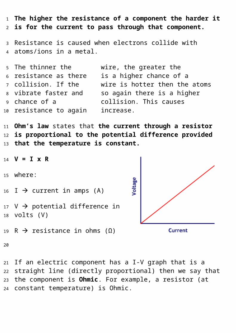
The higher the resistance of a component the harder it is for the current to pass through that component.
Resistance is caused when electrons collide with atoms/ions in a metal.
The thinner the wire, the greater the resistance as there is a higher chance of a collision. If the wire is hotter then the atoms vibrate faster and so again there is a higher chance of a collision. This causes resistance to again increase.
Ohm’s law states that the current through a resistor is proportional to the potential difference provided that the temperature is constant.
V = I x R
where:
I current in amps (A)
V potential difference in volts (V)
Resistance and Ohm’s Law
1
2
3
4
5
6
7
8
9
10
11
12
13
14
15

R resistance in ohms (Ω)
If an electric component has a I-V graph that is a straight line (directly proportional) then we say that the component is Ohmic. For example, a resistor (at constant temperature) is Ohmic.
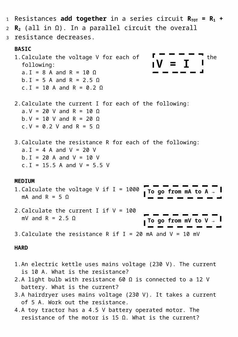
Resistances add together in a series circuit RTOT = R1 + R2 (all in Ω). In a parallel circuit the overall resistance decreases.
BASIC 1. Calculate the voltage V for each of the following:
a. I = 8 A and R = 10 Ωb. I = 5 A and R = 2.5 Ωc. I = 10 A and R = 0.2 Ω
2. Calculate the current I for each of the following:a. V = 20 V and R = 10 Ωb. V = 10 V and R = 20 Ωc. V = 0.2 V and R = 5 Ω
3. Calculate the resistance R for each of the following:a. I = 4 A and V = 20 Vb. I = 20 A and V = 10 Vc. I = 15.5 A and V = 5.5 V
MEDIUM1. Calculate the voltage V if I = 1000 mA and R = 5 Ω
2. Calculate the current I if V = 100 mV and R = 2.5 Ω
3. Calculate the resistance R if I = 20 mA and V = 10 mV
HARD
1. An electric kettle uses mains voltage (230 V). The current is 10 A. What is the resistance?2. A light bulb with resistance 60 Ω is connected to a 12 V battery. What is the current?3. A hairdryer uses mains voltage (230 V). It takes a current of 5 A. Work out the resistance.4. A toy tractor has a 4.5 V battery operated motor. The resistance of the motor is 15 Ω.
What is the current?5. A portable CD player takes a 6 V battery. The loudspeaker has a resistance of 4 Ω. What
is the maximum current through the loudspeaker?
To go from mA to A → ÷ 1000
To go from mV to V → ÷ 1000
V = I × R
1
2
3
4
5
6
7

6. A torch takes a 3 V battery. The light bulb for the torch has ‘0.2 A’ stamped on the side, so 3 V gives a current of 0.2 A. a What is the resistance of the bulb?b An old battery with voltage 1.5 V is used instead. How much current will flow through
the torch bulb?c What effect will this have on the torch?
7. A torch has resistance 120 Ω and the current is 100 mA. What is the battery voltage?8. When a 5 kΩ resistor is connected to a power supply 18 mA of current passes through it.
What is the voltage of the power supply?
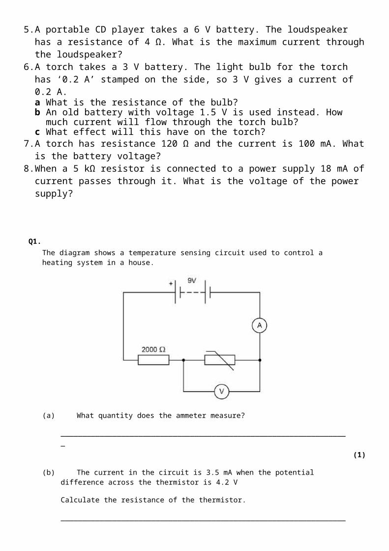
Q1.The diagram shows a temperature sensing circuit used to control a heating system in a house.
(a) What quantity does the ammeter measure?
___________________________________________________________________(1)
(b) The current in the circuit is 3.5 mA when the potential difference across the thermistor is 4.2 V
Calculate the resistance of the thermistor.
___________________________________________________________________
___________________________________________________________________
___________________________________________________________________
Resistance = ____________________ Ω(3)
(c) Calculate the charge that flows through the thermistor in 5 minutes when the current is 3.5 mA.
___________________________________________________________________
___________________________________________________________________

___________________________________________________________________
Charge = ____________________ C (3)
For a resistor the potential difference is proportional to the current, provided that the temperature is constant.
The resistor follows Ohm’s law (it’s an Ohmic conductor) and its resistance is constant.
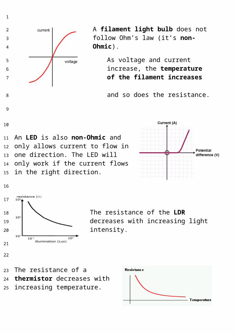
A filament light bulb does not follow Ohm’s law (it’s non-Ohmic).
As voltage and current increase, the temperature of the filament increases
and so does the resistance.
An LED is also non-Ohmic and only allows current to flow in one direction. The LED will only work if the current flows in the right direction.
Resistors
1
2
3
4
5
6
7
8
9
10
11
12
13
14
15
16
17
18
The resistance of the LDR decreases with increasing light intensity.
The resistance of a thermistor decreases with increasing temperature.
Task: Complete in your exercise book.
1. Draw the symbols for the following componentsa) Resistor b) Lamp c) LED
d) Thermistor e) LDR
2. The voltage across a bulb is measured for various different currents, with the results plotted opposite. a) At what voltage does the lamp stop acting
like an Ohmic conductor (i.e. when does it stop following Ohm’s law and being a straight line)?
b) What is the current when the Voltage is:i) 2V. ii) 6V. iii) 12V.
c) Calculate the resistance of the lamp at:i) 2V. ii) 6V. iii) 12V.
d) What do you notice happens to the resistance of the lamp as the voltage increases? e) Why does this happen to the resistance of the lamp?
3. The figure opposite shows the apparatus used to obtain the data needed to calculate the resistance of a thermistor at different temperatures. a) Use the data given in the figure to calculate the
resistance of the thermistor at 20 °C. b) Using a ruler and pencil for the axes, sketch a
graph that shows how the resistance of the thermistor would change as the temperature increases from 20 °C to 100 °C.
c) Give an example of a circuit that is likely to contain a thermistor.
d) The ammeter used in the circuit has a very low resistance. Why is it important that ammeters have a very low resistance?
1
2
3
4
5
6
7
8
e) A student plans to investigate how the resistance of an LDR changes with light intensity. The student starts with the apparatus show in the figure but makes three changes to the apparatus. One of the changes is to replace the thermistor with an LDR. Describe what other changes the student should make to the apparatus.
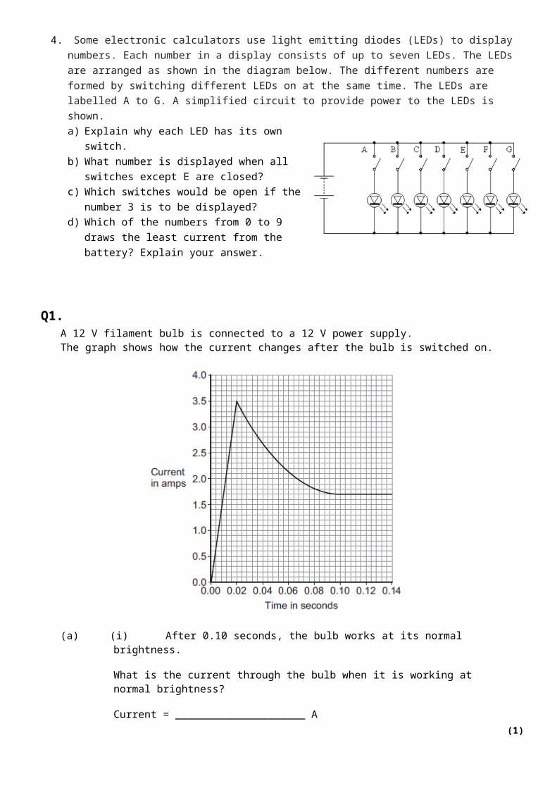
f) Draw a circuit diagram of the new apparatus (with LDR instead of thermistor). 4. Some electronic calculators use light emitting diodes (LEDs) to display numbers. Each
number in a display consists of up to seven LEDs. The LEDs are arranged as shown in the diagram below. The different numbers are formed by switching different LEDs on at the same time. The LEDs are labelled A to G. A simplified circuit to provide power to the LEDs is shown. a) Explain why each LED has its own switch.b) What number is displayed when all switches except E are closed?c) Which switches would be open if the number 3 is to
be displayed?d) Which of the numbers from 0 to 9 draws the least
current from the battery? Explain your answer.
Q1.A 12 V filament bulb is connected to a 12 V power supply.The graph shows how the current changes after the bulb is switched on.
(a) (i) After 0.10 seconds, the bulb works at its normal brightness.
What is the current through the bulb when it is working at normal brightness?
Current = _____________________ A(1)
(ii) The bulb works at normal brightness for 30 seconds before it is switched off.
Calculate the charge that flows through the bulb in the 30 seconds before it is switched off. Give the unit.
______________________________________________________________
______________________________________________________________
______________________________________________________________
Charge = _________________ unit _________________(3)
(iii) Calculate the energy transferred by the 12 V bulb when it is working at normal brightness for 30 seconds.
______________________________________________________________
______________________________________________________________
Energy transferred = _____________________ J(2)
(b) Between 0.02 seconds and 0.08 seconds, there is an increase in both the resistance and the temperature of the metal filament inside the bulb.
Explain, in terms of the electrons and ions inside the filament, why both the temperature and the resistance increase.
___________________________________________________________________
___________________________________________________________________
___________________________________________________________________
___________________________________________________________________
___________________________________________________________________
___________________________________________________________________(2)
(Total 8 marks)

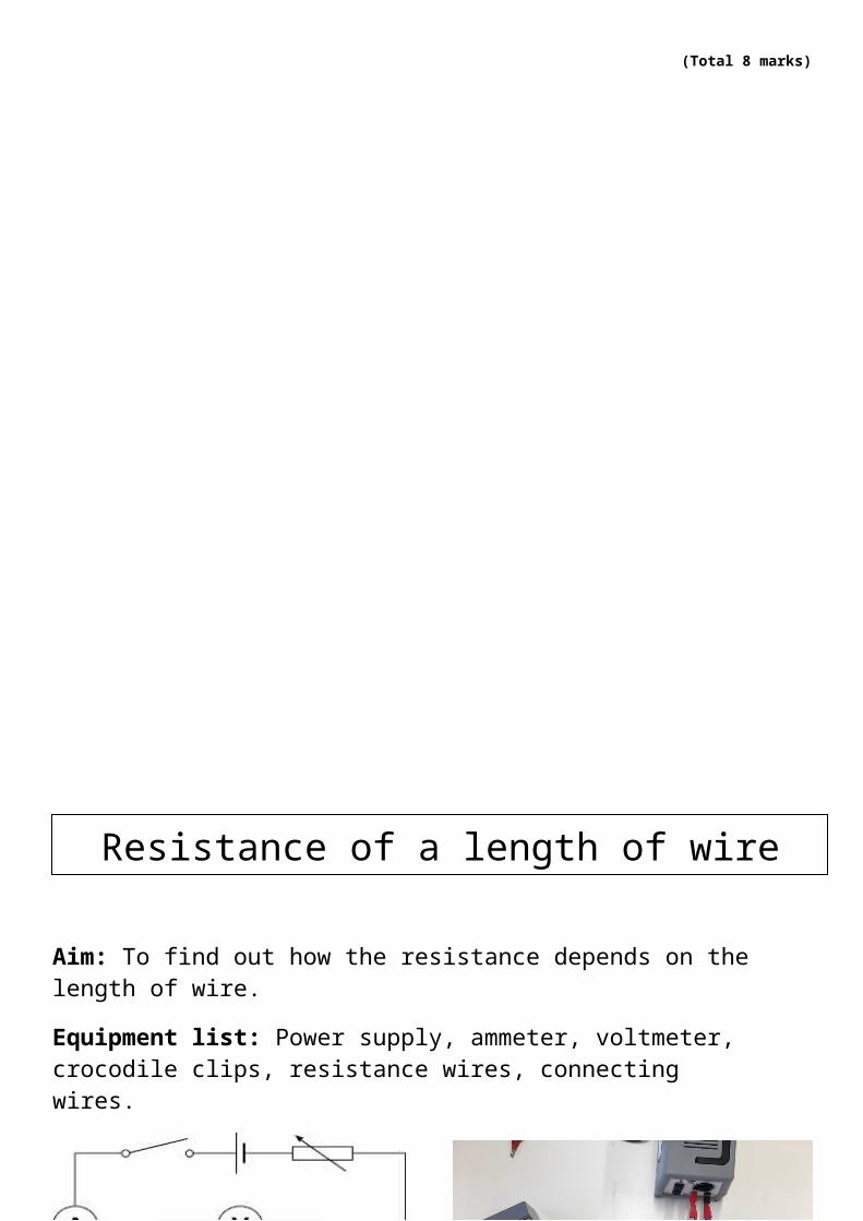
Aim: To find out how the resistance depends on the length of wire.
Equipment list: Power supply, ammeter, voltmeter, crocodile clips, resistance wires, connecting wires.
How does the resistance of a wire depend on its length?
A dimmer switch allows you to control the brightness of a lamp. In this experiment you will investigate how the dimmer switch works. You will construct a circuit to measure the potential difference across a wire and the current in the wire. You will do this for different lengths of wire.
Method: You should read these instructions carefully before you start work.
1. Connect the circuit. It may be helpful to start at the positive side of the battery or power supply. This may be indicated by a red socket.
2. Connect a lead from the red socket to the positive side of the ammeter.
Resistance of a length of wire
3. Connect a lead from the negative side of the ammeter (this may be black) to the crocodile clip at the zero end of the ruler.
4. Connect a lead from the other crocodile clip to the negative side of the battery. The main loop of the circuit is now complete. Use this lead as a switch to disconnect the battery between readings.
5. Connect a lead from the positive side of the voltmeter to the crocodile clip the ammeter is connected to.6. Connect a lead from the negative side of the voltmeter to the other crocodile clip.
7. Record the length of the wire between the crocodile clips, and the readings on the ammeter and voltmeter in a suitable table.
8. Move the crocodile clip and record the new ammeter and voltmeter readings. Note that the voltmeter reading may not change. Repeat this to obtain several pairs of meter readings for different lengths of wire.
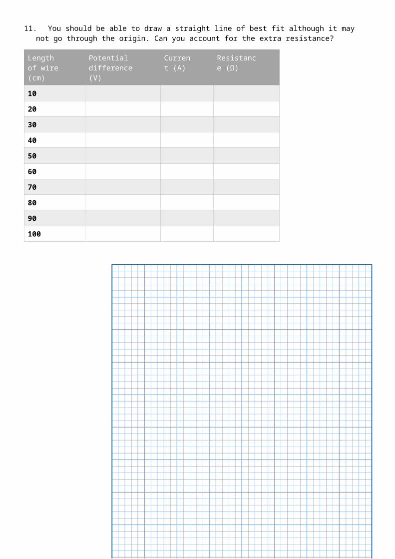
9. Calculate and record the resistance for each length of wire using the equation: R = V ÷ I10. Plot a graph of resistance in Ω against length in cm. 11. You should be able to draw a straight line of best fit although it may not go through the origin. Can you account
for the extra resistance?
Length of wire (cm)
Potential difference (V)
Current (A)
Resistance (Ω)
10
20
30
40
50
60
70
80
90
100

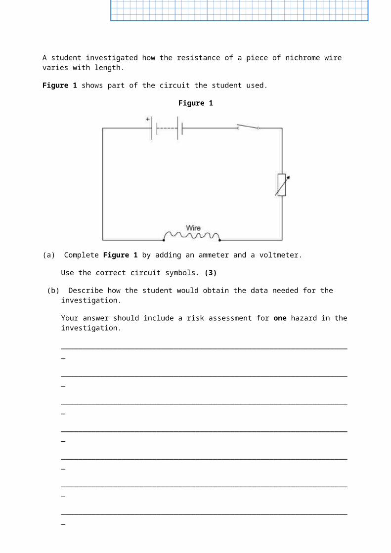
A student investigated how the resistance of a piece of nichrome wire varies with length.
Figure 1 shows part of the circuit the student used.
Figure 1
(a) Complete Figure 1 by adding an ammeter and a voltmeter.
Use the correct circuit symbols. (3)
(b) Describe how the student would obtain the data needed for the investigation.
Your answer should include a risk assessment for one hazard in the investigation.
___________________________________________________________________
___________________________________________________________________
___________________________________________________________________
___________________________________________________________________
___________________________________________________________________
___________________________________________________________________
___________________________________________________________________
___________________________________________________________________
___________________________________________________________________
___________________________________________________________________
___________________________________________________________________
___________________________________________________________________(6)
(c) Why would switching off the circuit between readings have improved the accuracy of the student’s investigation?
Tick one box.
The charge flow through the wire would not change.
The potential difference of the battery would not increase.
The power output of the battery would not increase.
The temperature of the wire would not change.
(1)
(d) The student used crocodile clips to make connections to the wire.
They could have used a piece of equipment called a ‘jockey’.
Figure 2 shows a crocodile clip and a jockey in contact with a wire.
Figure 2

How would using the jockey have affected the accuracy and resolution of the student’s results compared to using the crocodile clip?
Tick two boxes.
The accuracy of the student’s results would be higher.
The accuracy of the student’s results would be lower.
The accuracy of the student’s results would be the same.
The resolution of the length measurement would be higher.
The resolution of the length measurement would be lower.
The resolution of the length measurement would be the same.
(2)(Total 12 marks)
Aim: To change the current I in a circuit in order to find the resistance R of the following components:
1) Filament light bulb.2) Resistor3) Diode
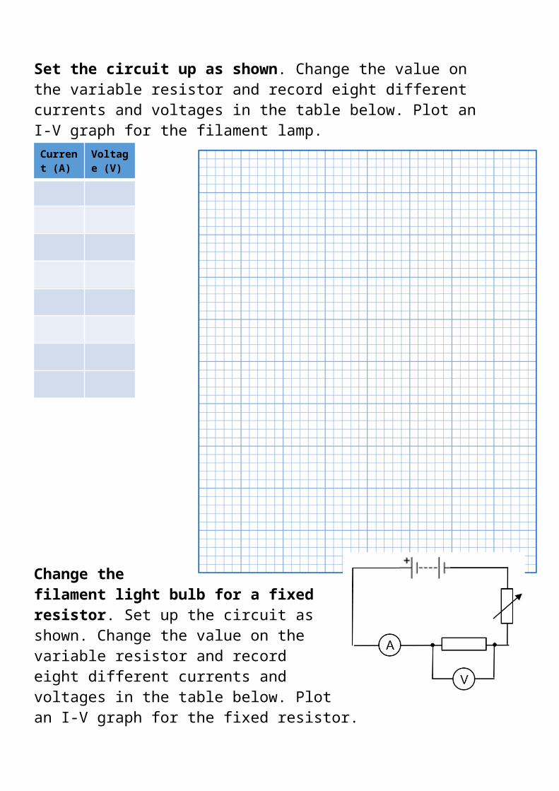
Set the circuit up as shown. Change the value on the variable resistor and record eight different currents and voltages in the table below. Plot an I-V graph for the filament lamp.
Change the filament light bulb for a fixed resistor. Set up the circuit as shown. Change the
I-V curves
Current (A)
Voltage (V)

value on the variable resistor and record eight different currents and voltages in the table below. Plot an I-V graph for the fixed resistor.
Change the filament light bulb for a diode. Be careful to set up the diode in the correct direction
Current (A)
Voltage (V)
(polarity). Change the value on the variable resistor and record eight different currents and voltages in the table below. Plot an I-V graph for the fixed resistor.
A student wants to
Current (A)
Voltage (V)
investigate how the current through a filament lamp affects its resistance.
(a) Use the circuit symbols in the boxes to draw a circuit diagram that she could use.
12 V battery
variableresistor
filamentlamp voltmeter ammeter
(2)
(b) Describe how the student could use her circuit to investigate how the current through a filament lamp affects its resistance.
___________________________________________________________________
___________________________________________________________________
___________________________________________________________________
___________________________________________________________________
___________________________________________________________________
___________________________________________________________________
___________________________________________________________________
___________________________________________________________________(4)

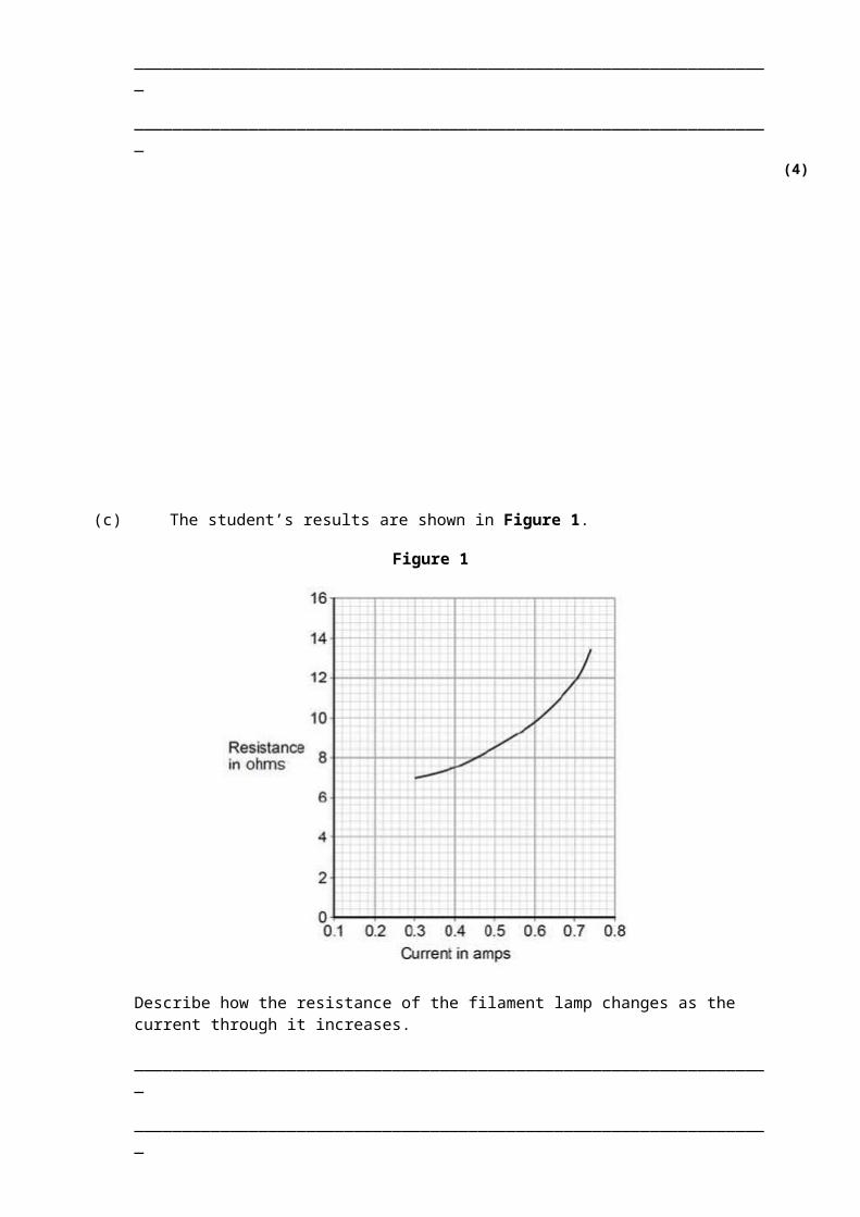
(c) The student’s results are shown in Figure 1.
Figure 1
Describe how the resistance of the filament lamp changes as the current through it increases.
___________________________________________________________________
___________________________________________________________________(1)
(d) Use Figure 1 to estimate the resistance of the filament lamp when a current of 0.10 A passes through the lamp.
Resistance = _____________________ Ω(1)
(e) The current-potential difference graphs of three components are shown in Figure 2.
Use answers from the box to identify each component.
diode filament lamp light dependent resistor
resistor at constant temperature thermistor
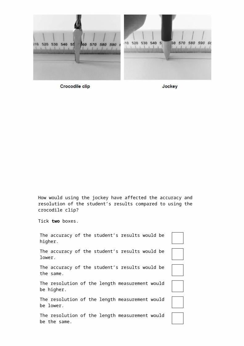
Figure 2
__________________________
__________________________
__________________________(3)
(Total 11 marks)

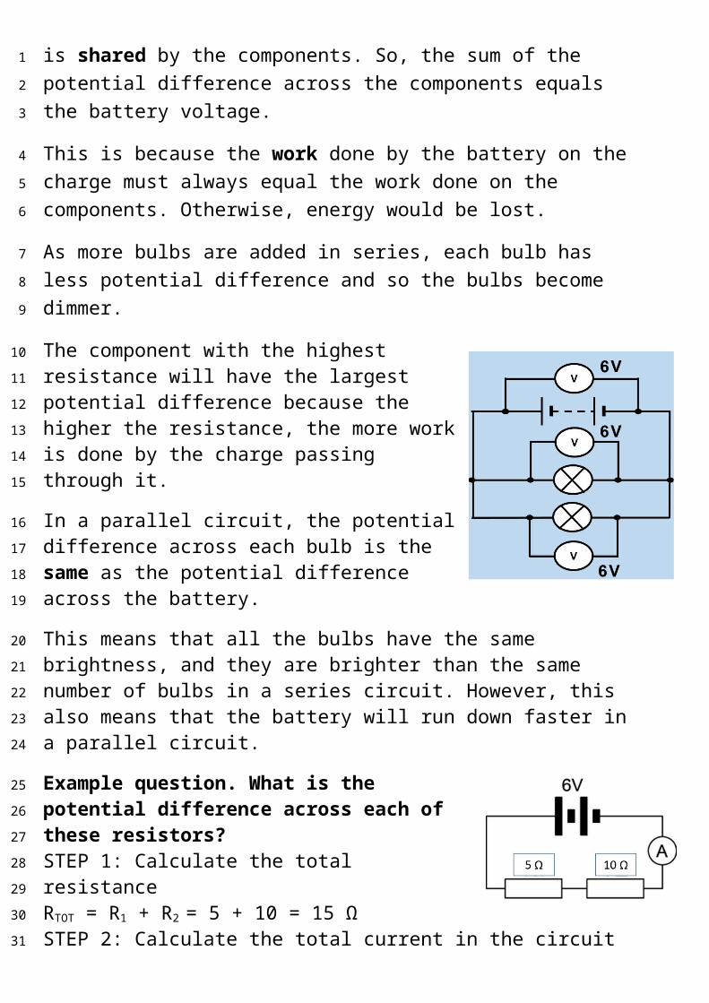
In a series circuit, the voltage supplied by the battery is shared by the components. So, the sum of the potential difference across the components equals the battery voltage.
This is because the work done by the battery on the charge must always equal the work done on the components. Otherwise, energy would be lost.
As more bulbs are added in series, each bulb has less potential difference and so the bulbs become dimmer.
The component with the highest resistance will have the largest potential difference because the higher the resistance, the more work is done by the charge passing through it.
In a parallel circuit, the potential difference across each bulb is the same as the potential difference across the battery.
This means that all the bulbs have the same brightness, and they are brighter than the same number of bulbs in a series circuit. However, this also means that the battery will run down faster in a parallel circuit.
Example question. What is the potential difference across each of these resistors?STEP 1: Calculate the total resistanceRTOT = R1 + R2 = 5 + 10 = 15 ΩSTEP 2: Calculate the total current in the circuitI = V ÷ R = 6 ÷ 15 = 0.4 ASTEP 3: Calculate the potential difference across both of the resistors5 Ohm resistor: V = I × R = 0.4 × 5 = 2V10 Ohm resistor: V = I × R = 0.4 × 10 = 4V
Note that these potential differences add up to give the total potential difference across the battery (6V).
Potential difference in series & parallel1
2
3
4
5
6
7
8
9
10
11
12
13
14
15
16
17
18
19
20
21
22
23
24
25
26
27
28
2930
31
32
Basic
1. A 1.5 V cell is connected to a 3.0 Ω resistor and a 2.0 Ω resistor in series with each other. A. Draw a circuit diagram for this circuitB. Calculate:
(I) The total resistance of the two resistors (II) The current through the resistors (III) The potential differences across each resistor
Medium
2. A circuit contains a battery of two cells, with each cell providing 1.5 V. The circuit also has two resistors connected in series. Resistor P has a resistance of 2 Ω and resistor Q has a resistance of 10 Ω. A. Draw a circuit diagram for this circuit. B. Calculate the total resistance of the two resistors C. Calculate the total potential difference provided by the battery D. Show that the current through the battery is 0.25 AE. Calculate the potential difference across each resistor
3. A circuit contains a 6 V battery and three resistors connected in parallel with each other and with the battery. R1 = 2 ΩR2 = 3 ΩR3 = 6 Ωa. Draw a circuit diagram for this circuitb. Calculate the current through each resistor c. Calculate the current through the battery
Hard
4. The battery in this circuit has a potential difference of 12V, each bulb has a resistance of 5Ω, calculate the current in A1, A2 and A3
5. The two bulbs are identical, calculate the voltage over them6. What would happen to the brightness of
the bulbs if you added another bulb in series with the first two?
7. What would happen to the brightness of the bulbs if you added another two bulbs in parallel to the first two? A2
A3A1

The diagram shows a simple type of car rear window heater. The six heating elements are exactly the same and are connected in series.
Each heating element has a resistance of 5 Ω. The current passing through each element is 0.4 A.
(a) Calculate the total resistance of the six heating elements. Show clearly how you work out your answer. (2)
___________________________________________________________________
___________________________________________________________________
___________________________________________________________________
(b) Why is the current passing through each element the same? (1)
___________________________________________________________________
___________________________________________________________________
(c) What is the total current passing through the whole circuit? (1)
___________________________________________________________________
___________________________________________________________________
(d) How is the 12-volt potential difference of the car battery shared between the six heating elements? (1)
___________________________________________________________________
___________________________________________________________________
___________________________________________________________________

As the temperature increases, the resistance of a thermistor decreases. This can be used in a circuit that controls when central heating of a flat/house turns on and off.
As the light intensity increase, the resistance of an LDR decrease. This can be used to automatically turn street lights on/off when it gets dark/light.
If the light level increases:
a) Resistance of LDR will decrease.
b) Voltage across the LDR will decrease.
c) Voltage across the resistor will increase.
d) Overall current in the circuit will increase.
Worked example.
The graph shows how the resistance of an LDR varies with light level. The circuit shows how the LDR is connected to a computer circuit. The computer circuit turns on the street light when the potential difference across it is less than 3V.
When the light intensity is 45 lux:
Q1 What is the resistance of the LDR?
1000 ΩQ2 What is the total resistance of the circuit?
RTOT = R1 + R2 = 1000 + 1000 = 2000 ΩQ3 What is the current in the circuit?
I = V ÷ R = 6 ÷ 2000 = 0.003 AQ4 What is the potential difference across the fixed resistor?
V = I × R = 0.003 × 1000 = 3 VQ5 Will the street lights be on or off?
Off, as the potential difference is not less than 3V. The graph shows how the resistance of an LDR varies with light level. Task: Complete in your exercise book
Sensing circuits1
2
3
4
5
6
7
8
9
10
11
12
13
14
15
16
17
18
19
20
21
22
23
24
25
26
2728

The circuit shows how the LDR is connected to a computer circuit. The computer circuit turns on the street light when the p.d. across it is less than 3V.
When the light intensity is 80 lux:
1. What is resistance of the LDR?
2. What is the total resistance of the circuit?3. What is the current in the circuit?4. What is the p.d. across the fixed resistor?5. Will the street lights be on or off?
When the light intensity is 10 lux6. What is resistance of the LDR?7. What is the total resistance of the circuit?8. What is the current in the circuit?9. What is the p.d. across the fixed resistor?10.Will the street lights be on or off?
When the computer circuit has 3V across it11.What is the current through the fixed resistor?12.What is the total resistance of the circuit?13.What is the resistance of the LDR?14.What is the light intensity?
To enable the light intensity at which the street light comes on to be varied, the fixed resistor is replaced with a variable resistor.
15. What value should the variable resistor have so that the switch comes on when the light intensity is 50 lux?
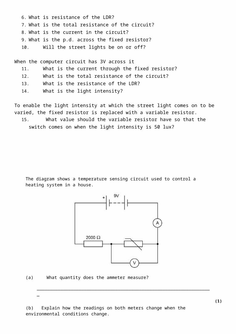
The diagram shows a temperature sensing circuit used to control a heating system in a house.
6V
1000
(a) What quantity does the ammeter measure?
___________________________________________________________________(1)
(b) Explain how the readings on both meters change when the environmental conditions change. (6)
___________________________________________________________________
___________________________________________________________________
___________________________________________________________________
___________________________________________________________________
___________________________________________________________________
___________________________________________________________________
___________________________________________________________________
___________________________________________________________________
___________________________________________________________________
___________________________________________________________________
___________________________________________________________________
___________________________________________________________________
___________________________________________________________________
___________________________________________________________________
___________________________________________________________________
___________________________________________________________________
(c) The current in the circuit is 3.5 mA when the potential difference across the thermistor is 4.2 V

Calculate the resistance of the thermistor.
___________________________________________________________________
___________________________________________________________________
___________________________________________________________________
Resistance = ____________________ Ω(3)
(d) Calculate the charge that flows through the thermistor in 5 minutes when the current is 3.5 mA.
___________________________________________________________________
___________________________________________________________________
___________________________________________________________________
Charge = ____________________ C(3)
(e) The circuit shown in the diagram can be modified to turn lights on and off by replacing the thermistor with a Light Dependent Resistor (LDR).
Draw the circuit symbol for an LDR in the space below.
(1)(Total 14 marks)

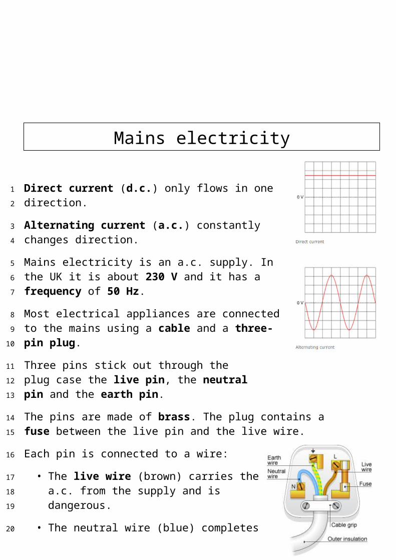
Direct current (d.c.) only flows in one direction.
Alternating current (a.c.) constantly changes direction.
Mains electricity is an a.c. supply. In the UK it is about 230 V and it has a frequency of 50 Hz.
Most electrical appliances are connected to the mains using a cable and a three-pin plug.
Three pins stick out through the plug case the live pin, the neutral pin and the earth pin.
The pins are made of brass. The plug contains a fuse between the live pin and the live wire.
Each pin is connected to a wire:
• The live wire (brown) carries the a.c. from the supply and is dangerous.
• The neutral wire (blue) completes the circuit and is usually set at 0V. It is still dangerous as a.c. flows through it.
• The Earth wire (green and yellow) is a safety wire and it is set at 0V. It doesn’t normally carry current, but if there is a fault, the a.c. flows from live to Earth.
The fuse melts and breaks the circuit if a fault in an appliance causes too much current flow. Circuit breakers also break the circuit when the current is too high, but are resettable by a switch.
Task: Complete in your exercise book
Mains electricity1
2
3
4
5
6
7
8
9
10
11
12
13
14
15
16
17
18
19
20
21
22
23
24
Basic
1. a) How does alternating current differ to direct current?b) What is the frequency of the a.c. mains electricity supply in the UK?c) What is the voltage of UK mains electricity?
2. What are the names and colours of the three pins in a plug?3. a) Why are pins in a plug made of brass?
b) Why is the outer casing of a plug made of plastic?4. a) What is the purpose of a fuse?
b) What causes a fuse to break the circuit?c) Give one advantage of a circuit breaker over a fuse?
Medium
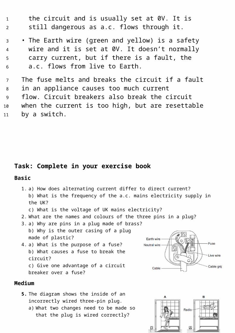
5. The diagram shows the inside of an incorrectly wired three-pin plug. a) What two changes need to be made so that the plug is wired correctly? b) The fuse inside a plug is a safety device. Explain what
happens when too much current passes through a fuse.c) Using the hairdryer in picture A is dangerous. However,
it is safe to use the battery-operated radio in picture B. Explain why.
6. The diagram to the below shows someone accidentally touching a live wire inside a dismantled 230 V mains electricity socket.
a) The total resistance to current flow is 50 kΩ. Calculate the current that will flow through the person. (Hint: you need to use Ohm’s law and rearrange the equation).
b) Rubber is a good insulator. Explain why it is a good idea for electricians to wear rubber soled boots when working.
Hard
7. A hairdryer designed to be used with the UK mains supply has a plastic cover. The cable connecting the hairdryer to the plug does not have an Earth wire. Why does the hairdryer not need a cable with an Earth wire?
8. An oscilloscope (this is a device used for measuring and showing voltage over time) is connected to an alternating current (ac) supply. The diagram shows the trace produced on the oscilloscope screen. Each horizontal division on the oscilloscope screen represents 0.002 s. Calculate the frequency of the alternating current supply. Hint: frequency is a measure of how many cycles the current makes every second.
To go from kΩ to Ω → × 1000

Q1.(a) Use numbers given in the box to complete the following sentences.
12 50 110 230
In the UK, the mains electricity supply is ________________________________ volts. The frequency of the UK mains electricity supply is _______________________ hertz.
(2)
(b) The diagram shows a hairdryer designed to be used with the UK mains supply. The cable connecting the hairdryer to the plug does not have an earth wire.
(i) Why does the hairdryer not need a cable with an earth wire?

__________________________________________________________________________________ (1)
(ii) Which one of the following materials are the two wires inside the cable made from?
Draw a ring around your answer.
aluminium copper steel(1)
(Total 4 marks)Q2.
(a) The diagram below shows the three pins in a mains plug. The pins connect with the live, neutral and earth terminals in a socket.
On the diagram, label each pin to show which is: the live pin, the neutral pin, the earth pin.
(3)
(b) The diagram to the left shows the inside of a mains plug.
(i) Name one material which could be used for the part labelled X.
_________________________________________________________
(ii) Complete the sentences below.
The part labelled Y is called the ___________________________________ .
This is used to hold the _______________________________ firmly in place.
The component labelled Z is the ___________________________________ .
(iii) The plug is used with an electric fire.Which part of the electric fire is connected to the earth pin?
______________________________________________________________(5)
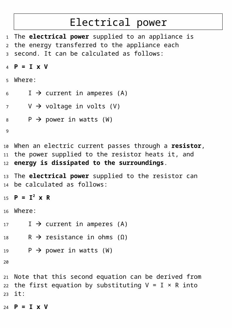
The electrical power supplied to an appliance is the energy transferred to the appliance each second. It can be calculated as follows:
P = I x V
Where:
Electrical power
1
2
3
4

I current in amperes (A)
V voltage in volts (V)
P power in watts (W)
When an electric current passes through a resistor, the power supplied to the resistor heats it, and energy is dissipated to the surroundings.
The electrical power supplied to the resistor can be calculated as follows:
P = I2 x R
Where:
I current in amperes (A)
R resistance in ohms (Ω)
P power in watts (W)
Note that this second equation can be derived from the first equation by substituting V = I × R into it:
P = I x V
P = I x I x R
P = I2 x R
Task: Complete in your exercise book
BASIC 1. Calculate the power P for each of the following:
a. I = 8 A and V = 20 Vb. I = 5 A and R = 2.5 Ωc. I = 2 A and V = 0.2Vd. I = 0.1 A and R = 0.2 Ω
2. Calculate the current I for each of the following:a. V = 20 V and P = 10 W
1
2
3
4
5
6
7
8
9
10
11
12
13
14
15
16
17
18

b. V = 10 V and P = 0.2 Wc. P = 5.5 W and R = 2.2 Ωd. P = 0.2 W and R = 1.5 Ω
3. Calculate the resistance R for each of the following:a. I = 4 A and P = 20 Wb. I = 20 A and P = 50,000 Wc. I = 0.015 A and P = 0.055 W
MEDIUM1. A light bulb is connected to a 2V supply and experiences a current of 6.4A. What is the power rating
of the bulb?
2. A kettle has a power rating of 1500w. What is the potential difference that it must be supplied with to have a current flowing through it of 30A?
3. A student attaches a 10V supply to a bulb with a power rating of 100w. What is the current running through the bulb?
4. The student now instead connects a 25w bulb to the same supply. What is the difference between the current going through this bulb compared to the 100w bulb?
5. An electric radiator has a power of 2,000 W, and a resistance of 20 Ω. Calculate the current in the circuit.
6. A household circuit can deliver a maximum of 13 Amps at a voltage of 230V. Calculate the maximum power this circuit can output.
HARD1. An electric radiator has a power of 3 kW, and a current
of 3 Amps. Calculate the resistance in the circuit. 2. An electric transformer outputs a voltage of 500 kV, and
a current of 100 mA is drawn from the circuit. Calculate the power drawn by the circuit. 3. A microwave has a power of 1 kW, and a resistance of 55 Ω. Calculate the current in the circuit. 4. An iPhone charger outputs a current of 3,000 mA at a power of 50 W. Calculate the voltage given
out by the charger. 5. A desktop computer uses a power of 0.5 kW, at a current of 5 A. Calculate the resistance of the
computer.
Q1.The image shows a battery-powered drone.
To go from kW to W → × 1000
To go from mA to A → ÷ 1000

(a) The battery in the drone can store 97.5 kJ of energy.
When the drone is hovering, the power output of the battery is 65.0 W
Calculate the time for which the drone can hover.
___________________________________________________________________
___________________________________________________________________
___________________________________________________________________
___________________________________________________________________
___________________________________________________________________
___________________________________________________________________
Time = ____________________ seconds(3)
(b) The battery powers 4 motors in the drone.
Each motor has a resistance of 1.60 Ω when the power input to each motor is 19.6 W
The 4 motors are connected in parallel with the battery.
Calculate the current through the battery.
___________________________________________________________________
___________________________________________________________________
___________________________________________________________________
___________________________________________________________________
___________________________________________________________________
___________________________________________________________________
___________________________________________________________________
Current = ____________________ A(4)
(Total 7 marks)•
The national grid is made up of transformers and transmission cables.
Directly after a power station is a step-up transformer. This increases the voltage but decreases the current. This reduces the energy lost to heating in the cables, making the transmission of electricity more efficient.
The cables are also low resistance to reduce energy lost to heating. Before electricity is delivered to consumers it goes to a step down transformer which reduces the voltage to a safe level for consumers. 230V is typically used for use in homes and other buildings.
Mini task:
The figure below represents parts of the National Grid.
a) Match the parts 1–4 in the list below with the labels A–D in the figure.
1 Domestic user ____________
2 Power station ____________
3 Step-down transformer ____________
4 Step-up transformer ____________
b) Write the correct voltage from the list below in each box in the figure.
230 V 25 kV 132 kV
National Grid1
2
3
4
5
6
7
8
9
10
11
12
13
14
15

Main Task. The National Grid is a network of cables, pylons and transformers that distributes (‘shares out’) electrical energy across the UK.The diagram shows a simplified model of the National Grid system.1. Which letter represents the power station? __________2. Which letters represent a pylon? ________ and ________3. Which letter represents the cables of the National Grid? ________4. Which letter represents a house close to the power station? ________5. Which letter represents a house far away from the power station? ________6. Bulb B is brighter than / the same brightness as / dimmer than bulb A.7. This happens because energy is gained / remains constant / is lost as electric current travels through the cable because of resistance.8. The wasted / gained energy results in heating / cooling of the cables.9. This system can be described as efficient / inefficient because some energy is wasted instead of being transferred usefully.10. Which Sankey Diagram best represents the energy transfer to bulb B in this model?
This diagram shows a more realistic model of the National Grid system.11. Name the two items that have been added. ________________________12. What is the letter of the step up transformer? ________13. What is the letter of the step down transformer? ________14. Bulb B is brighter than / has a similar brightness to / dimmer than bulb A.15. This indicates that more / less energy is being wasted compared with the simple model.
16. (a) This indicates that the system is more / less efficient than before. (b) Which Sankey Diagram could show the energy transfer to Bulb B now? 17. The step up transformer increases / decreases the voltage of the power supply.18. This results in the current being stepped down / stepped up.19. The same amount of energy is being transferred as before: however, it is being transmitted as a high / low voltage rather than a high / low current.20. More / The same / Less energy is lost because the energy is carried as a large voltage rather than as a large current.21. The step down transformer increases / decreases the voltage to a safer level before it is used by the consumer.

Q1.The diagram shows how electricity is distributed from power stations to consumers.
(a) (i) What name is given to the network of cables and transformers that links power stations to consumers?
______________________________________________________________(1)
(ii) What does a step-up transformer do?
______________________________________________________________(1)
(iii) Explain why step-up transformers are used in the electricity distribution system.
______________________________________________________________
______________________________________________________________
______________________________________________________________
______________________________________________________________(2)
(b) Most of the world’s electricity is generated in power stations that burn fossil fuels.
State one environmental problem that burning fossil fuels produces.
___________________________________________________________________
___________________________________________________________________(1)
(c) Electricity can be generated using energy from the wind. A company wants to build a new wind farm. Not everyone thinks that this is a good idea.
(i) What arguments could the company give to persuade people that a wind farm is a good idea?
______________________________________________________________
______________________________________________________________
______________________________________________________________
______________________________________________________________(2)
(ii) What reasons may be given by the people who think that wind farms are not a good idea?
______________________________________________________________
______________________________________________________________
______________________________________________________________
______________________________________________________________(2)
(Total 9 marks)
Electron —> negative chargeProton —> positive chargeNeutron —> no charge
Usually, atoms are neutral (have no overall charge). Their number of protons is equal to the number of electrons.
Only electrons can be transferred to and from an atom. A charged atom is called an ion.
Some objects are more attractive to electrons than others. If you rub a balloon (very attractive to other atoms’ electrons) together with a woollen jumper. Some of the electrons will be transferred from the jumper to the balloon, leaving the jumper positively charged and leaving the balloon negatively charged.
Two static electricity rules:
1. Opposite charges attract.
2. Like charges repel.
A van de Graaff generator is like an industrial version of rubbing a balloon on a jumper, transferring electrons from one place to another. It was originally used to accelerate electrons to very high speed.
Static electricity1
2
3
4
5
6
7
8
9
10
11
12
13
14
15
16
17
18
19
20
21
22
23
24
25
26
27
28
29

Static charge questionsBasic
1 Complete the following sentences using words from the list below.
equal negative opposite positive zero
c) A proton has …………….. charge.
d) A neutron has …………….. charge.
e) An electron has …………….. charge.
f) A proton and an electron have …………….. and …………….. charge.
Medium2 Complete the following sentences using words from the list below.
electron(s) ion(s) neutron(s) nucleus (nuclei) proton(s)
a) Every atom contains a …………….. which is positively charged.
b) The nucleus of an atom is composed of …………….. and ……………...
c) The …………….. in an atom move about in the space surrounding the nucleus.
d) An uncharged atom has equal numbers of …………….. and ……………...
e) A charged atom is called an ……………...
f) An uncharged atom becomes charged as a result of transferring …………….. to or from it.
Hard3 In an experiment, an insulator becomes negatively charged when it is rubbed with a dry cloth.
a) In terms of electron transfer, explain why the insulator becomes negatively charged.
....................................................................................................................................................
....................................................................................................................................................
....................................................................................................................................................
b) Explain why the insulator does not lose its charge.
....................................................................................................................................................
....................................................................................................................................................
....................................................................................................................................................
4 A positively charged object, X, and another charged object, Y, repel each other.
a) What is the type of charge on Y?
....................................................................................................................................................
b) Y is removed and a negatively charged object, Z, is brought near to X. State whether X
and Z attract or repel each other.
....................................................................................................................................................

A force field is caused by non-contact forces. These forces do not need to be in physical contact (touching) for an interaction of forces to take place. Attraction/repulsion of static charges is an example of a non-contact forces.
Electric field lines flow away from positive charges and towards negative charges. The arrows show the direction a positive charge would move in the field.
The closer together the field lines are, the stronger the field. The strength of the field depends on two things:
1) The size of the charge.
2) The distance away from the charge
The closer together the electric field lines, the stronger the electric field.
Electric fields1
2
3
4
5
6
7
8
9
10
11
12
13
14
15
16
17

An electrostatic precipitator is used to take smoke particles out of waste gases.
1. Smoke particles pick up a negative charge.
2. Smoke particles are attracted to the collecting plates.
3. Collecting plates are knocked to remove smoke particles.
Photocopies also make use of electrostatics:
1. Photoconductor is negatively charged.
2. White parts of paper reflect light & release areas of negative charge.
3. Toner (ink particles) is positively charged.
4. Toner attracted to areas of leftover negative charge
Printers work in the following way:
Ink particles are positively charged.
Computer controls voltage on plates, controlling deflection. Task: Complete in your exercise book
Uses of electrostatics

Basic
1. Like charges ________, unlike charges _________. 2. Which charged particle is negatively charged?3. Name three devices that use electrostatics. 4. The diagram to the right shows how static
electricity is used to paint a metal car panel. Use words from the box to complete the following sentences.
All the paint droplets have the same type of charge. This makes the paint droplets __________ each other and spread out. The car panel and the paint droplets have the _____________ type of charge. This causes the car panel to __________ the paint droplets. The car panel is covered by an even layer of paint.
Medium
5. Name a situation in which static electricity is dangerous and not useful. Give a reason for your answer. 6. Describe how an electrostatic precipitator works (3). 7. Describe how a photocopier works (4). 8. Describe how an ink-jet printer works (2).
9. The diagram to the left shows a student touching the metal dome of a Van de Graaf generator. When the generator is switched on, the metal dome becomes negatively charged. Explain why the student’s hair stands on end when the generator is switched on. (2)
Hard
10. Polyethylene terephthalate (PET) and polyvinyl chloride (PVC) are two common types of plastic that can be recycled from household waste. They need to be separated in the recycling plant. The waste plastics are crushed into small chips and tumbled together. The PET chips become positively charged. The PVC chips become negatively charged.a) Explain how the PET chips become positively charged and the
PVC chips become negatively charged. (2)b) The mixture is dropped onto a rotating drum.
The mixture sticks to the outside of the drum.The mixture goes past a metal rod that has a positive charge. PVC chips leave the drum and fall into the collecting bin on the right. Explain why the PVC chips leave the drum. (2)
c) The PET chips are carried round until they reach the scraper. They fall into the collecting bin on the left. Both of the bins and the scraper are connected to earth. Suggest why the bins are the scraper are connected to earth. (1)

