web-i joist • design...
TRANSCRIPT

CATEGORY 1WEB-i® JOIST DESIGN MANUAL
1
WEB-i® JOIST • DESIGN MANUAL


WEB-i® JOIST DESIGN MANUAL TABLE OF CONTENTS
WEB-i 4412 Parallel . . . . . . . . . . . . . . . . . . . . . . . . . . . . . . . . . . . . . . . . . . 16
WEB-i 4512 Parallel . . . . . . . . . . . . . . . . . . . . . . . . . . . . . . . . . . . . . . . . . . 17
WEB-i 4712 Parallel . . . . . . . . . . . . . . . . . . . . . . . . . . . . . . . . . . . . . . . . . . 18
WEB-i 4532 Parallel . . . . . . . . . . . . . . . . . . . . . . . . . . . . . . . . . . . . . . . . . . 19
WEB-i 4732 Parallel . . . . . . . . . . . . . . . . . . . . . . . . . . . . . . . . . . . . . . . . . . 20
WEB-i 4412 Taper 1/4”/Ft . Slope . . . . . . . . . . . . . . . . . . . . . . . . . . . . . . . . 24
WEB-i 4412 Taper 3/8”/Ft . Slope . . . . . . . . . . . . . . . . . . . . . . . . . . . . . . . . 25
WEB-i 4512 Taper 1/4”/Ft . Slope . . . . . . . . . . . . . . . . . . . . . . . . . . . . . . . . 26
WEB-i 4512 Taper 3/8”/Ft . Slope . . . . . . . . . . . . . . . . . . . . . . . . . . . . . . . . 27
WEB-i 4712 Taper 1/4”/Ft . Slope . . . . . . . . . . . . . . . . . . . . . . . . . . . . . . . . 28
WEB-i 4712 Taper 3/8”/Ft . Slope . . . . . . . . . . . . . . . . . . . . . . . . . . . . . . . . 29
15, 23
10
11
12
13
14
14
14
12
10
9
8
8
7
6
4-5
3
2
1


WEB-i® JOIST DESIGN MANUAL
1
WEB-i® PRODUCT DESCRIPTION
CODE ACCEPTANCE:ICC-ES Report ESR-2974City of Los Angeles Research Report RR 25824
SERIES CODE
FLANGE GRADE WEB DEPTH
RANGE
4212 1650F-1 .5E 3/8” 11 7/8” to 24”
4312 1800F-1 .6E 3/8” 11 7/8” to 24”
4412 2100F-1 .8E 3/8” 11 7/8” to 24”
4512 2400F-2 .0E 3/8” 11 7/8” to 24”
4612 2700F-2 .2E 3/8” 11 7/8” to 24”
4712 2850F-2 .3E 3/8” 11 7/8” to 24”
4232 1650F-1 .5E 1/2” 16” to 28”
4332 1800F-1 .6E 1/2” 16” to 28”
4432 2100F-1 .8E 1/2” 16” to 28”
4532 2400F-2 .0E 1/2” 16” to 28”
4632 2700F-2 .2E 1/2” 16” to 28”
4732 2850F-2 .3E 1/2” 16” to 28”
Flange Species: DF, HF, SPF, ES/LP & LP

WEB-i® JOIST DESIGN MANUAL
2
TYPICAL WEB-i® BEARING AND BLOCKING DETAILS
2x4 WEBSTIFFENERS
2x6 WEBSTIFFENERS
2x6 WEBSTIFFENERS
2x4 ENDBLOCKING
WEB-i®BLOCKING
PANELS
WEB-i®BLOCKING
PANEL
WEB-i®BLOCKING
PANEL
WEB-i®BLOCKING
PANEL

WEB-i® JOIST DESIGN MANUAL
3
TYPICAL JOIST HANGER DETAILS
2x4 WEBSTIFFENERS

WEB-i® JOIST DESIGN MANUAL
4
HANGER DETAILS

WEB-i® JOIST DESIGN MANUAL
5
HANGER DETAILS

WEB-i® JOIST DESIGN MANUAL
6
ROOF JOIST DETAILS

WEB-i® JOIST DESIGN MANUAL
7
RIM JOIST DETAILS
WEB-i®RIM JOIST

WEB-i® JOIST DESIGN MANUAL
8
SQUASH BLOCK DETAILSBLOCKING PANEL • RIM JOISTS • CUT BACK
•
•
BLOCKING PANELS OR RIM JOIST ALLOWABLE VERTICAL LOAD (PLF) 1,2
Web 11 7/8” 14” 16” 18” 20” 22” 24” 26” 28”3/8” 2150 2050 1950 1500 1400 1200 1000 ---- ----1/2” ---- ---- 2450 1850 1750 1500 1250 1000 950

WEB-i® JOIST DESIGN MANUAL
9
OUTRIGGER DETAILS
OUTRIGGER CAPACITY IN POUNDS PER LINEAR FOOT (SLG/REP) (D.F. #2)
Outrigger Length (L)
2-2x4 2-2x6 2-2x8100% Floor 115% Roof 125% Roof 100% Floor 115% Roof 125% Roof 100% Floor 115% Roof 125% Roof
2’-0” 334/385 385/442 418/4812’-6” 214/246 246/283 267/3083’-0” 148/171 171/196 186/214 318/366 366/421 398/4573’-6” 109/115 125/144 136/157 234/269 269/309 292/336 375/431 431/496 469/5394’-0” 77/77 96/110 104/120 179/206 206/237 224/257 287/330 330/380 359/4134’-6” 54/54 76/87 82/87 141/162 162/187 177/203 227/261 261/300 283/3265’-0” 39/39 61/63 63/63 114/131 131/151 143/164 183/211 211/243 229/2645’-6” 29/28 47/47 47/47 94/109 109/125 118/136 152/174 174/201 190/2186’-0” 79/89 91/105 99/114 127/146 146/168 159/1836’-6” 67/70 78/89 84/97 108/125 125/143 136/1567’-0” 56/56 67/77 73/84 93/107 107/124 117/1347’-6” 45/45 58/67 63/73 81/94 94/108 102/1178’-0” 37/37 51/59 56/60 71/82 82/95 89/103

WEB-i® JOIST DESIGN MANUAL
10
WEB STIFFENER REQUIREMENTS / CONCENTRATED LOAD LOCATIONS
WEB STIFFENER NAILING
Depth (IN .)
Simple Span Continuous Span3/8” WEB 1/2” WEB 3/8” WEB 1/2” WEB
12 3-10d ---- 4-10d ----14 4-10d ---- 6-10d ----16 4-10d 4-10d 6-10d 6-10d18 5-10d 5-10d 7-10d 7-10d20 6-10d 6-10d 9-10d 9-10d22 6-10d 6-10d 9-10d 9-10d24 7-10d 7-10d 10-10d 10-10d26 ---- 8-10d ---- 12-10d28 ---- 8-10d ---- 12-10d

WEB-i® JOIST DESIGN MANUAL
11
ALLOWABLE HOLE SIZES
Joist Depth (IN .)
Effective Height (EH)3 4 5 6 7 8 9 10 11 12 14 16 18 20 22
12 0 .1463 0 .1951 0 .2439 0 .292714 0 .1224 0 .1633 0 .2041 0 .2449 0 .2857 0 .326516 0 .1053 0 .1404 0 .1754 0 .2105 0 .2456 0 .2807 0 .3158 0 .350918 0 .0923 0 .1231 0 .1538 0 .1846 0 .2154 0 .2462 0 .2769 0 .3077 0 .3385 0 .369220 0 .0822 0 .1096 0 .1370 0 .1644 0 .1918 0 .2192 0 .2466 0 .274 0 .3014 0 .3288 0 .383622 0 .0741 0 .0988 0 .1235 0 .1481 0 .1728 0 .1975 0 .2222 0 .2469 0 .2716 0 .2963 0 .3457 0 .395124 0 .0674 0 .0899 0 .1124 0 .1348 0 .1573 0 .1798 0 .2022 0 .2247 0 .2472 0 .2697 0 .3146 0 .3596 0 .404526 0 .0619 0 .0825 0 .1031 0 .1237 0 .1443 0 .1649 0 .1856 0 .2062 0 .2268 0 .2474 0 .2887 0 .3299 0 .3711 0 .412428 0 .0571 0 .0762 0 .0952 0 .1143 0 .1333 0 .1524 0 .1714 0 .1905 0 .2095 0 .2286 0 .2667 0 .3048 0 .3429 0 .381 0 .419

WEB-i® JOIST DESIGN MANUAL
12
NON-BEARING PARTITION DETAILS BEVEL PLATE REQUIREMENTS
BEVEL PLATE REQUIRED WHEN SLOPE IS EQUAL OR GREATER THAN SHOWN.

WEB-i® JOIST DESIGN MANUAL
13
WEIGHT OF MATERIALS
REFER TO LOCAL BUILDING CODE OR UBC FOR DESIGN REQUIREMENTS OF LIVE LOAD AND OTHER LOADS.
Nominal Size
Schedule 10 Thin Wall
Schedule 40 Standard Pipe
Dry plf Wet plf Dry plf Wet plf1 .00” 1 .4 1 .8 1 .7 2 .11 .25” 1 .8 2 .5 2 .3 2 .91 .50” 2 .1 3 .0 2 .7 3 .62 .00” 2 .6 4 .2 3 .7 5 .12 .50” 3 .5 5 .9 5 .8 7 .93 .00” 4 .3 8 .0 7 .6 10 .83 .50” 5 .0 9 .8 9 .2 13 .44 .00” 5 .6 11 .8 10 .8 16 .35 .00” 7 .8 17 .3 14 .6 23 .36 .00” 12 .9 26 .7 19 .0 31 .58 .00” 16 .9 40 .5 28 .6 50 .810 .0” 21 .2 58 .1 40 .6 74 .6
Nominal Size
Joist or Stud Spacing12 in . 16 in . 24 in .
2x4 1 .4 psf 1 .1 psf 0 .7 psf2x6 2 .2 psf 1 .7 psf 1 .1 psf2x8 2 .9 psf 2 .2 psf 1 .5 psf
2x10 3 .7 psf 2 .8 psf 1 .9 psf2x12 4 .4 psf 3 .3 psf 2 .2 psf

WEB-i® JOIST DESIGN MANUAL
14
DEFLECTION CALCULATION CAMBER • RECOMMENDED NAIL SPACING
For cantilevers use 2L/___ @ TL and/or 2L/___ @ ∆L with limits shown above for downward deflections.
With plaster ceiling use l/360 @ ∆L .TL = Total Load∆L = Deflection Load (L or S or Lr)
1) For tighter on center spacing, consider pre-drilling holes no greater than 0.75 x nail diameter to prevent splitting. (per 1997 NDS SEC 12.1.3.1
2) 7/16” min. O.D. crown width and 1 1/16” min. penetration into chord member.
3) If more than (1) one row, offset rows at least 1/2”.
WEB-i® JOISTS CAN BE MADE WITH 2,250 FT. RADIUS (CAMBER) UPON REQEST. Camber
Recommended Nail Spacing
NOTE: See allowable Properties table for appropriate WEB-i® series load tables (pages 16-20) or code report for values of EI and K used in above equations.
Floor* Roof
Residentiall/240 @ TL and/or l/360 @ ∆L (min .) orl/360 @ TL and/or l/480 @ ∆L (Preferred)
Flat (0”/ft to <1/8”/ft) - NOT ALLOWED
Slope (1/8”/ft to 1/4”/ft) l/240 @ TL and/or l/360 @ ∆L
Slope (1/4”/ft & Greater) l/180 @ TL and/or l/240 @ ∆LNon-Residentiall/360 @ TL and/or l/480 @ ∆L (min .) orl/480 @ TL and/or l/600 @ ∆L (Preferred)
Nail Size
Staple Size
Minimum (O .C . SPG)
8d Box 15 Ga . 3 .75”8d Com 13 Ga . 4 .50”
10d Box 14 Ga . 4 .25”
10d Com 12 Ga . 5 .00”
12d Box 14 Ga . 4 .25”
12d Com 12 Ga . 5 .00”
16d Box 13 Ga . 4 .50”
16d Com 12 Ga . 5 .50”
WEB-i® JOIST DESIGN MANUAL
15
INSTRUCTIONS FOR USING LOAD TABLES
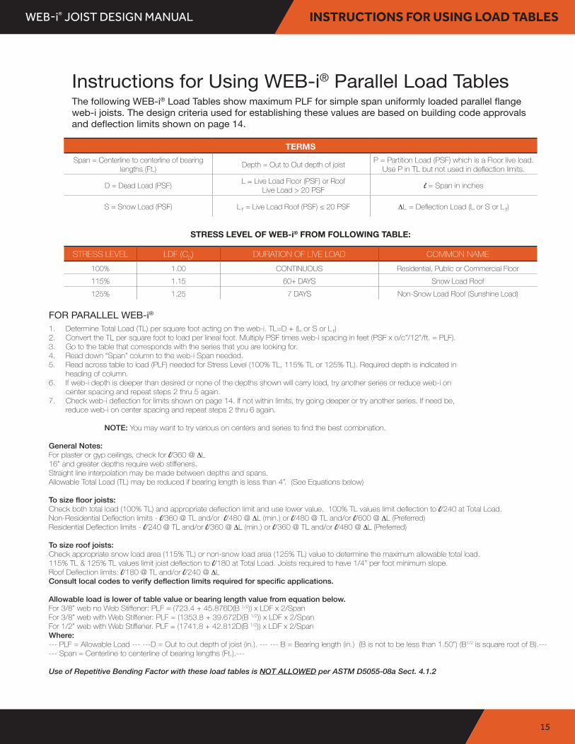
Instructions for Using WEB-i® Parallel Load TablesThe following WEB-i® Load Tables show maximum PLF for simple span uniformly loaded parallel flange web-i joists. The design criteria used for establishing these values are based on building code approvals and deflection limits shown on page 14.
FOR PARALLEL WEB-i®1 . Determine Total Load (TL) per square foot acting on the web-i. TL=D + (L or S or L r)2 . Convert the TL per square foot to load per lineal foot. Multiply PSF times web-i spacing in feet (PSF x o/c”/12”/ft. = PLF).3 . Go to the table that corresponds with the series that you are looking for.4 . Read down “Span” column to the web-i Span needed.5 . Read across table to load (PLF) needed for Stress Level (100% TL, 115% TL or 125% TL). Required depth is indicated in
heading of column.6 . If web-i depth is deeper than desired or none of the depths shown will carry load, try another series or reduce web-i on
center spacing and repeat steps 2 thru 5 again.7 . Check web-i deflection for limits shown on page 14. If not within limits, try going deeper or try another series. If need be,
reduce web-i on center spacing and repeat steps 2 thru 6 again.
NOTE: You may want to try various on centers and series to find the best combination. General Notes: For plaster or gyp ceilings, check for l/360 @ ∆L 16” and greater depths require web stiffeners. Straight line interpolation may be made between depths and spans . Allowable Total Load (TL) may be reduced if bearing length is less than 4”. (See Equations below)
To size floor joists:Check both total load (100% TL) and appropriate deflection limit and use lower value. 100% TL values limit deflection to l/240 at Total Load . Non-Residential Deflection limits - l/360 @ TL and/or l/480 @ ∆L (min .) or l/480 @ TL and/or l/600 @ ∆L (Preferred)Residential Deflection limits - l/240 @ TL and/or l/360 @ ∆L (min .) or l/360 @ TL and/or l/480 @ ∆L (Preferred)
To size roof joists:Check appropriate snow load area (115% TL) or non- snow load area (125% TL) value to determine the maximum allowable total load. 115% TL & 125% TL values limit joist deflection to l/180 at Total Load. Joists required to have 1/4” per foot minimum slope.Roof Deflection limits: l/180 @ TL and/or l/240 @ ∆LConsult local codes to verify deflection limits required for specific applications.
Allowable load is lower of table value or bearing length value from equation below.For 3/8” web no Web Stiffener: PLF = (723.4 + 45.876D(B 1/2)) x LDF x 2/Span For 3/8” web with Web Stiffener: PLF = (1353.8 + 39.672D(B 1/2)) x LDF x 2/SpanFor 1/2” web with Web Stiffener. PLF = (1741.8 + 42.812D(B 1/2)) x LDF x 2/SpanWhere:--- PLF = Allowable Load --- ---D = Out to out depth of joist (in.). --- --- B = Bearing length (in.) (B is not to be less than 1.50”) (B1/2 is square root of B).--- --- Span = Centerline to centerline of bearing lengths (Ft.).---
Use of Repetitive Bending Factor with these load tables is NOT ALLOWED per ASTM D5055- 08a Sect. 4.1.2
TERMSSpan = Centerline to centerline of bearing
lengths (Ft .) Depth = Out to Out depth of joist P = Partition Load (PSF) which is a Floor live load. Use P in TL but not used in deflection limits.
D = Dead Load (PSF) L = Live Load Floor (PSF) or Roof Live Load > 20 PSF l = Span in inches
S = Snow Load (PSF) L r = Live Load Roof (PSF) ≤ 20 PSF ∆L = Deflection Load (L or S or L r)
STRESS LEVEL OF WEB-i® FROM FOLLOWING TABLE:
STRESS LEVEL LDF (CD) DURATION OF LIVE LOAD COMMON NAME100% 1 .00 CONTINUOUS Residential, Public or Commercial Floor115% 1 .15 60+ DAYS Snow Load Roof125% 1 .25 7 DAYS Non-Snow Load Roof (Sunshine Load)

WEB-i® JOIST DESIGN MANUAL
16
WEB-i® 4412 PARALLEL
WEB-i® 4412 Load Table3/8” OSB Web & 2x4 MSR 2100f-1.8E Flange
Allowable Uniform Load (PLF)Depth (In.)
11 7/8” 14” 16” 18” 20” 22” 24”Span(Ft.)
100% TL 115% TL 100% TL 115% TL 100% TL 115% TL 100% TL 115% TL 100% TL 115% TL 100% TL 115% TL 100% TL 115% TL Span(Ft.)l/600 ∆ 125% TL l/600 ∆ 125% TL l/600 ∆ 125% TL l/600 ∆ 125% TL l/600 ∆ 125% TL l/600 ∆ 125% TL l/600 ∆ 125% TL
10’ 385 443 429 493 470 540 511 587 552 634 593 681 633 728 10’314 482 426 536 587 639 690 741 792
12’ 321 369 357 411 391 450 426 489 460 529 494 568 528 607 12’202 401 279 447 359 489 532 575 617 660
14’ 275 316 306 352 335 386 365 419 394 453 423 487 452 520 14’137 344 191 383 248 419 311 456 378 492 529 565
16’ 216 248 260 299 293 337 319 367 345 396 370 426 396 455 16’96 270 135 325 178 367 224 399 275 431 329 463 388 495
18’ 170 196 205 236 238 274 271 312 304 349 329 378 352 404 18’70 213 99 257 131 298 166 339 205 380 247 411 292 440
20’ 131 159 166 191 193 222 219 252 246 283 273 314 299 344 20’52 173 74 208 99 241 126 274 156 308 189 341 225 374
22’ 100 131 137 158 159 183 181 208 203 234 225 259 247 284 22’40 134 57 172 76 199 98 227 121 254 148 282 176 309
24’ 78 104 112 133 134 154 152 175 171 196 189 218 208 239 24’31 104 45 144 60 167 77 190 96 213 117 237 140 260
26’ 62 83 90 113 114 131 130 149 145 167 161 185 177 203 26’25 83 36 120 48 142 62 162 77 182 94 201 113 221
28’ 50 67 73 97 97 113 112 129 125 144 139 160 152 175 28’20 67 29 97 39 123 50 140 63 157 77 174 92 191
30’ 41 55 59 79 80 98 97 112 109 125 121 139 133 153 30’16 55 23 79 32 107 41 122 52 136 63 151 76 166
32’ 45 49 66 66 86 85 98 96 110 106 122 117 134 32’45 19 66 26 89 34 107 43 120 53 133 64 146
34’ 38 41 55 56 75 72 87 85 98 94 108 103 119 34’38 16 55 22 75 29 95 36 106 45 118 54 129
36’ 32 47 47 63 61 78 76 87 84 96 92 106 36’32 47 19 63 24 82 31 95 38 105 46 115
38’ 40 40 54 52 70 66 78 75 86 83 95 38’40 16 54 21 70 26 85 32 94 39 103
40’ 34 46 45 60 57 70 68 78 74 86 40’34 46 18 60 23 76 28 85 34 93
42’ 30 40 52 49 64 61 71 67 78 42’30 40 52 19 66 24 77 29 84
44’ 35 46 43 58 53 64 61 71 44’35 46 17 58 21 70 26 77
l/600 ∆ column is PLF Load that will cause l/600 Deflection. For other deflection limits, use following: l/180 ∆ Load = l/600 ∆ Value x 3.3333, l/240 ∆ Load = l/600 ∆Value x 2.5000, l/360 ∆ Load = l/600 ∆ Value x 1.6667, l/480 ∆ Load = l/600 ∆ Value x 1 .2500
V = Shear in pounds M = Moment in foot-pounds EI = MOE x I in pounds 0 inch 2 x 10⁶ K = Shear Deflection Constant in pounds x 106 W = Weight in plf
Allowable Properties @ 100% per ESR-2974
DepthProp . 11 7/8” 14” 16” 18” 20” 22” 24” Prop .
V 1,929.0 2,147.0 2,351.0 2,556.0 2,760.0 2,965.0 3,169.0 VM 6,921.0 8,335.0 9,665.0 10,995.0 12,325.0 13,655.0 14,985.0 MEI 532 .0 779 .0 1,059.0 1,385.0 1,759.0 2,182.0 2,656.0 EIK 5 .64 6 .65 7 .60 8 .55 9 .50 10 .45 11 .40 KW 3 .6 3 .8 4 .0 4 .2 4 .4 4 .6 4 .8 W

WEB-i® JOIST DESIGN MANUAL
17
WEB-i® 4512 PARALLEL
WEB-i® 4512 Load Table3/8” OSB Web & 2x4 MSR 2400f-2.0E Flange
Allowable Uniform Load (PLF)Depth (In.)
11 7/8” 14” 16” 18” 20” 22” 24”Span(Ft.)
100% TL 115% TL 100% TL 115% TL 100% TL 115% TL 100% TL 115% TL 100% TL 115% TL 100% TL 115% TL 100% TL 115% TL Span(Ft.)l/600 ∆ 125% TL l/600 ∆ 125% TL l/600 ∆ 125% TL l/600 ∆ 125% TL l/600 ∆ 125% TL l/600 ∆ 125% TL l/600 ∆ 125% TL
10’ 385 443 429 493 470 540 511 587 552 634 593 681 633 728 10’336 482 536 587 639 690 741 792
12’ 321 369 357 411 391 450 426 489 460 529 494 568 528 607 12’219 401 300 447 384 489 532 575 617 660
14’ 275 316 306 352 335 386 365 419 394 453 423 487 452 520 14’148 344 207 383 268 419 334 456 492 529 565
16’ 241 277 268 308 293 337 319 367 345 396 370 426 396 455 16’105 301 147 335 192 367 242 399 296 431 354 463 495
18’ 192 240 238 274 261 300 284 326 306 352 329 378 352 404 18’76 256 108 298 142 326 180 355 222 383 267 411 315 440
20’ 144 192 203 234 235 270 255 293 276 317 296 340 316 364 20’57 192 81 254 108 293 137 319 170 345 205 370 243 396
22’ 110 147 158 193 195 224 222 255 248 286 269 309 288 331 22’44 147 63 210 83 244 107 277 132 311 161 336 191 360
24’ 86 115 124 162 164 188 186 214 209 240 231 266 254 292 24’34 115 49 165 66 205 84 233 105 261 128 289 153 317
26’ 69 92 99 132 132 160 159 182 178 204 197 227 216 249 26’27 92 39 132 53 174 68 198 85 222 103 246 123 270
28’ 55 74 80 107 107 138 137 157 153 176 170 195 186 214 28’22 74 32 107 43 143 55 171 69 192 84 212 101 233
30’ 45 61 66 88 88 118 114 137 133 153 148 170 162 187 30’18 61 26 88 35 118 45 149 57 167 70 185 84 203
32’ 50 54 73 73 98 95 120 117 135 130 149 143 164 32’50 21 73 29 98 38 127 47 147 58 162 70 178
34’ 42 46 61 62 82 80 106 100 119 115 132 126 145 34’42 18 61 24 82 32 107 40 130 49 144 59 158
36’ 35 52 52 70 68 90 85 106 103 118 113 130 36’35 52 21 70 27 90 34 114 42 128 50 141
38’ 30 44 45 60 58 77 73 95 90 106 101 116 38’30 44 18 60 23 77 29 98 36 115 43 126
40’ 38 51 50 67 63 84 78 95 91 105 40’38 51 20 67 25 84 31 104 37 114
42’ 33 44 43 58 55 73 67 87 82 95 42’33 44 17 58 22 73 27 90 32 103
44’ 39 51 48 64 59 79 71 87 44’39 51 19 64 23 79 28 94
V = Shear in pounds M = Moment in foot-pounds EI = MOE x I in pounds 0 inch 2 x 10⁶ K = Shear Deflection Constant in pounds x 106 W = Weight in plf
Allowable Properties @ 100% per ESR-2974
DepthProp . 11 7/8” 14” 16” 18” 20” 22” 24” Prop .
V 1,929.0 2,147.0 2,351.0 2,556.0 2,760.0 2,965.0 3,169.0 VM 8,459.0 10,187.0 11,812.0 13,438.0 15,063.0 16,689.0 18,315.0 MEI 591 .0 866 .0 1,176.0 1,539.0 1,954.0 2,425.0 2,951.0 EIK 5 .64 6 .65 7 .60 8 .55 9 .50 10 .45 11 .40 KW 3 .6 3 .8 4 .0 4 .2 4 .4 4 .6 4 .8 W
l/600 ∆ column is PLF Load that will cause l/600 Deflection. For other deflection limits, use following: l/180 ∆ Load = l/600 ∆ Value x 3.3333, l/240 ∆ Load = l/600 ∆Value x 2.5000, l/360 ∆ Load = l/600 ∆ Value x 1.6667, l/480 ∆ Load = l/600 ∆ Value x 1 .2500

WEB-i® JOIST DESIGN MANUAL
18
WEB-i® 4712 PARALLEL
WEB-i® 4712 Load Table3/8” OSB Web & 2x4 MSR 2850f-2.3E Flange
Allowable Uniform Load (PLF)Depth (In.)
11 7/8” 14” 16” 18” 20” 22” 24”Span(Ft.)
100% TL 115% TL 100% TL 115% TL 100% TL 115% TL 100% TL 115% TL 100% TL 115% TL 100% TL 115% TL 100% TL 115% TL Span(Ft.)l/600 ∆ 125% TL l/600 ∆ 125% TL l/600 ∆ 125% TL l/600 ∆ 125% TL l/600 ∆ 125% TL l/600 ∆ 125% TL l/600 ∆ 125% TL
10’ 385 443 429 493 470 540 511 587 552 634 593 681 633 728 10’367 482 536 587 639 690 741 792
12’ 321 369 357 411 391 450 426 489 460 529 494 568 528 607 12’241 401 329 447 489 532 575 617 660
14’ 275 316 306 352 335 386 365 419 394 453 423 487 452 520 14’165 344 229 383 295 419 456 492 529 565
16’ 241 277 268 308 293 337 319 367 345 396 370 426 396 455 16’117 301 164 335 214 367 268 399 326 431 463 495
18’ 214 246 238 274 261 300 284 326 306 352 329 378 352 404 18’86 267 121 298 159 326 201 355 246 383 295 411 347 440
20’ 162 216 214 246 235 270 255 293 276 317 296 340 316 364 20’65 216 92 268 121 293 154 319 189 345 228 370 269 396
22’ 125 167 178 224 213 245 232 267 250 288 269 309 288 331 22’50 167 71 237 94 267 120 290 148 313 179 336 213 360
24’ 98 131 140 187 186 225 213 244 230 264 247 284 264 303 24’39 131 56 187 74 244 95 266 118 287 143 308 171 330
26’ 78 104 112 150 149 192 190 218 212 244 228 262 243 280 26’31 104 45 150 59 199 76 237 95 265 116 285 138 304
28’ 63 84 91 122 122 162 157 188 183 211 203 233 223 256 28’25 84 36 122 48 162 62 204 78 229 95 254 114 279
30’ 52 69 75 100 100 134 129 164 159 183 177 203 194 223 30’20 69 30 100 40 134 51 173 64 199 79 221 94 243
32’ 43 57 62 83 83 111 108 144 135 161 155 179 170 196 32’17 57 25 83 33 111 43 144 54 175 66 194 79 213
34’ 48 52 70 70 94 91 121 114 143 137 158 151 174 34’48 21 70 28 94 36 121 45 152 56 172 67 189
36’ 41 44 59 60 80 77 103 97 127 119 141 135 155 36’41 17 59 24 80 31 103 39 130 47 153 57 168
38’ 35 50 51 68 66 88 83 111 102 127 121 139 38’35 50 20 68 26 88 33 111 41 137 49 151
40’ 30 43 44 59 57 76 72 96 88 114 107 125 40’30 43 17 59 22 76 28 96 35 118 42 136
42’ 38 51 49 66 62 83 77 103 93 114 42’38 51 19 66 25 83 30 103 37 124
44’ 33 44 43 58 55 73 67 90 81 103 44’33 44 17 58 22 73 27 90 32 109
V = Shear in pounds M = Moment in foot-pounds EI = MOE x I in pounds 0 inch 2 x 10⁶ K = Shear Deflection Constant in pounds x 106 W = Weight in plf
Allowable Properties @ 100% per ESR-2974
DepthProp . 11 7/8” 14” 16” 18” 20” 22” 24” Prop .
V 1,929.0 2,147.0 2,351.0 2,556.0 2,760.0 2,965.0 3,169.0 VM 10,107.0 12,171.0 14,113.0 16,056.0 17,998.0 19,940.0 21,882.0 MEI 680 .0 996 .0 1,353.0 1,770.0 2,247.0 2,788.0 3,394.0 EIK 5 .64 6 .65 7 .60 8 .55 9 .50 10 .45 11 .40 KW 3 .6 3 .8 4 .0 4 .2 4 .4 4 .6 4 .8 W
l/600 ∆ column is PLF Load that will cause l/600 Deflection. For other deflection limits, use following: l/180 ∆ Load = l/600 ∆ Value x 3.3333, l/240 ∆ Load = l/600 ∆Value x 2.5000, l/360 ∆ Load = l/600 ∆ Value x 1.6667, l/480 ∆ Load = l/600 ∆ Value x 1 .2500

WEB-i® JOIST DESIGN MANUAL
19
WEB-i® 4532 PARALLEL
WEB-i® 4532 Load Table1/2” OSB Web & 2x4 MSR 2400f-2.0E Flange
Allowable Uniform Load (PLF)Depth (In.)
16” 18” 20” 22” 24” 26” 28”Span(Ft.)
100% TL 115% TL 100% TL 115% TL 100% TL 115% TL 100% TL 115% TL 100% TL 115% TL 100% TL 115% TL 100% TL 115% TL Span(Ft.)l/600 ∆ 125% TL l/600 ∆ 125% TL l/600 ∆ 125% TL l/600 ∆ 125% TL l/600 ∆ 125% TL l/600 ∆ 125% TL l/600 ∆ 125% TL
10’ 599 688 637 733 675 777 714 821 752 865 791 910 829 954 10’748 796 844 893 941 989 1037
12’ 499 574 531 610 563 647 595 684 627 721 659 758 691 795 12’428 623 663 703 744 784 824 864
14’ 427 492 455 523 482 555 510 586 537 618 565 650 592 681 14’293 534 370 569 454 603 637 672 706 740
16’ 363 418 398 458 422 485 446 513 470 541 494 568 518 596 16’208 454 265 497 327 527 394 558 466 588 618 648
18’ 287 330 326 376 366 421 396 456 418 480 439 505 461 530 18’152 359 195 408 242 458 293 496 349 522 408 549 576
20’ 232 267 264 304 296 341 328 378 360 415 392 451 414 477 20’115 291 147 331 183 371 223 411 267 451 313 490 363 518
22’ 192 221 218 251 245 282 271 312 298 342 324 372 347 399 22’88 240 114 273 142 306 174 339 208 372 245 405 285 434
24’ 161 185 183 211 206 237 228 262 250 288 272 313 291 335 24’69 202 89 229 112 257 137 285 165 313 195 340 227 364
26’ 137 158 156 180 175 202 194 223 213 245 232 266 248 286 26’55 172 71 195 90 219 110 243 133 266 157 290 184 310
28’ 112 136 135 155 151 174 167 192 184 211 200 230 214 246 28’44 148 58 168 73 189 90 209 108 230 128 250 150 268
30’ 92 118 117 135 131 151 146 168 160 184 174 200 186 214 30’36 122 47 147 60 164 74 182 89 200 106 217 124 233
32’ 76 102 99 118 115 133 128 147 140 162 153 176 164 188 32’30 102 39 129 50 144 61 160 74 176 89 191 104 205
34’ 64 85 83 105 102 118 113 130 124 143 135 156 145 167 34’25 85 33 111 42 128 52 142 63 156 75 169 88 181
36’ 54 72 70 94 89 105 101 116 111 128 121 139 129 149 36’21 72 28 94 35 114 44 126 53 139 63 151 75 162
38’ 46 62 60 80 76 94 91 104 99 114 108 124 116 133 38’18 62 24 80 30 102 37 113 45 124 54 135 64 145
40’ 40 53 52 69 66 85 81 94 90 103 98 112 105 120 40’16 53 20 69 26 88 32 102 39 112 47 122 55 131
42’ 46 45 60 57 76 71 85 81 94 88 102 95 109 42’46 18 60 22 76 28 93 34 102 41 111 48 119
44’ 40 52 50 66 62 78 74 85 81 93 86 99 44’40 52 20 66 24 82 30 93 36 101 42 108
V = Shear in pounds M = Moment in foot-pounds EI = MOE x I in pounds 0 inch 2 x 10⁶ K = Shear Deflection Constant in pounds x 106 W = Weight in plf
Allowable Properties @ 100% per ESR-2974
DepthProp . 16” 18” 20” 22” 24” 26” 28” Prop .
V 2,995.0 3,187.0 3,379.0 3,572.0 3,764.0 3,957.0 4,149.0 VM 11,641.0 13,242.0 14,843.0 16,442.0 18,044.0 19,611.0 21,021.0 MEI 1,199.0 1,574.0 2,005.0 2,496.0 3,048.0 3,662.0 4,342.0 EIK 10 .13 11 .40 12 .67 13 .93 15 .20 16 .47 17 .73 KW 4 .5 4 .8 5 .1 5 .3 5 .6 5 .9 6 .2 W
l/600 ∆ column is PLF Load that will cause l/600 Deflection. For other deflection limits, use following: l/180 ∆ Load = l/600 ∆ Value x 3.3333, l/240 ∆ Load = l/600 ∆Value x 2.5000, l/360 ∆ Load = l/600 ∆ Value x 1.6667, l/480 ∆ Load = l/600 ∆ Value x 1 .2500
WEB-i® JOIST DESIGN MANUAL
20
WEB-i® 4732 PARALLEL
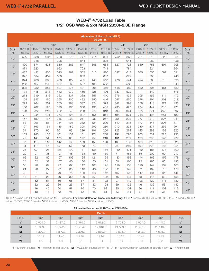
WEB-i® 4732 Load Table1/2” OSB Web & 2x4 MSR 2850f-2.3E Flange
Allowable Uniform Load (PLF)Depth (In.)
16” 18” 20” 22” 24” 26” 28”Span(Ft.)
100% TL 115% TL 100% TL 115% TL 100% TL 115% TL 100% TL 115% TL 100% TL 115% TL 100% TL 115% TL 100% TL 115% TL Span(Ft.)l/600 ∆ 125% TL l/600 ∆ 125% TL l/600 ∆ 125% TL l/600 ∆ 125% TL l/600 ∆ 125% TL l/600 ∆ 125% TL l/600 ∆ 125% TL
10’ 599 688 637 733 675 777 714 821 752 865 791 910 829 954 10’748 796 844 893 941 989 1037
12’ 499 574 531 610 563 647 595 684 627 721 659 758 691 795 12’471 623 663 703 744 784 824 864
14’ 427 492 455 523 482 555 510 586 537 618 565 650 592 681 14’325 534 409 569 603 637 672 706 740
16’ 374 430 398 458 422 485 446 513 470 541 494 568 518 596 16’233 467 295 497 362 527 435 558 588 618 648
18’ 332 382 354 407 375 431 396 456 418 480 439 505 461 530 18’171 415 218 442 270 469 326 496 387 522 549 576
20’ 278 319 316 363 337 388 357 410 376 432 395 455 414 477 20’129 347 165 395 206 422 250 446 297 470 348 494 403 518
22’ 229 264 261 300 293 337 324 373 342 393 359 413 377 433 22’100 287 128 326 160 366 195 405 233 427 274 449 318 471
24’ 193 222 219 252 246 283 272 313 299 344 325 374 345 397 24’78 241 101 274 126 307 154 341 185 374 218 406 254 432
26’ 157 189 187 215 209 241 232 267 255 293 277 318 297 341 26’62 205 81 234 101 262 124 290 149 318 177 346 206 371
28’ 127 163 161 185 180 208 200 230 219 252 239 274 256 294 28’51 170 66 201 83 226 101 250 122 274 145 298 169 320
30’ 105 140 136 161 157 181 174 200 191 220 208 239 223 256 30’42 140 54 175 68 197 84 218 101 239 120 260 140 279
32’ 87 116 113 142 138 159 153 176 168 193 183 210 196 225 32’34 116 45 151 57 173 70 191 84 210 100 228 118 245
34’ 73 97 95 125 120 141 135 156 149 171 162 186 173 199 34’29 97 38 127 48 153 59 169 71 186 85 202 99 217
36’ 62 82 80 107 102 125 121 139 133 153 144 166 155 178 36’24 82 32 107 40 136 50 151 60 166 72 180 85 193
38’ 53 70 69 92 87 112 108 125 119 137 129 149 139 160 38’21 70 27 92 35 116 43 136 52 149 62 162 73 173
40’ 45 61 59 79 75 100 93 112 107 123 117 134 125 144 40’18 61 23 79 30 100 37 122 45 134 53 146 63 156
42’ 52 51 69 65 87 81 102 97 112 106 122 113 130 42’52 20 69 26 87 32 108 39 122 46 132 55 142
44’ 46 45 60 57 76 70 93 85 102 96 111 103 119 44’46 18 60 22 76 28 94 34 111 41 121 48 129
V = Shear in pounds M = Moment in foot-pounds EI = MOE x I in pounds 0 inch 2 x 10⁶ K = Shear Deflection Constant in pounds x 106 W = Weight in plf
Allowable Properties @ 100% per ESR-2974
DepthProp . 16” 18” 20” 22” 24” 26” 28” Prop .
V 2,995.0 3,187.0 3,379.0 3,572.0 3,764.0 3,957.0 4,149.0 VM 13,909.0 15,822.0 17,734.0 19,646.0 21,559.0 23,431.0 25,116.0 MEI 1,379.0 1,810.0 2,306.0 2,870.0 3,505.0 4,212.0 4,993.0 EIK 10 .13 11 .40 12 .67 13 .93 15 .20 16 .47 17 .73 KW 4 .5 4 .8 5 .1 5 .3 5 .6 5 .9 6 .2 W
l/600 ∆ column is PLF Load that will cause l/600 Deflection. For other deflection limits, use following: l/180 ∆ Load = l/600 ∆ Value x 3.3333, l/240 ∆ Load = l/600 ∆Value x 2.5000, l/360 ∆ Load = l/600 ∆ Value x 1.6667, l/480 ∆ Load = l/600 ∆ Value x 1 .2500

WEB-i® JOIST DESIGN MANUAL NOTES

WEB-i® JOIST DESIGN MANUALNOTES

WEB-i® JOIST DESIGN MANUAL
23
WEB-i® INSTRUCTIONS FOR TAPER
Instructions for Using WEB-i® Tapered Load TablesThe following WEB-i® Tapered Load Tables show maximum PLF for simple span uniformly loaded tapered flange web-i joists. The design criteria used for establishing these values are based on building code approvals and deflection limits shown on page 14.
FOR TAPERED WEB-i®1 . Determine Total Load (TL) per square foot acting on the web-i. TL=D + (L or S or L r)2 . Convert the TL per square foot to load per lineal foot. Multiply PSF times web-i spacing in feet (PSF x o/c”/12”/ft. = PLF).3 . Go to the table that corresponds with the series that you are looking for.4 . Read down “Span” column to the web-i Span needed.5 . Read across table to load (PLF) needed for Stress Level (100% TL, 115% TL or 125% TL). Required depth is indicated in
heading of column.6 . If web-i depth is deeper than desired or none of the depths shown will carry load, try another series or reduce web-i on
center spacing and repeat steps 2 thru 5 again.7 . Check web-i deflection for limits shown on page 14. If not within limits, try going deeper or try another series. If need be,
reduce web-i on center spacing and repeat steps 2 thru 6 again.
NOTE: You may want to try various on centers and series to find the best combination. General Notes: For plaster or gyp ceilings, check for l/360 @ ∆L 16” and greater depths require web stiffeners. Straight line interpolation may be made between depths and spans . Allowable Total Load (TL) may be reduced if bearing length is less than 4”. (See Equations below)
To size roof joists:Check appropriate snow load area (115% TL) or non-snow load area (125% TL) value to determine the maximum allowable total load. 115% TL & 125% TL values limit joist deflection to l/180 and Total Load. Joists required to have 1/4” per foot minimum slope.
Roof Deflection limits: l/180 @ TL and/or l/240 @ ∆L .
Consult local codes to verify deflection limits required for specific applications.
Allowable load is lower of table value or bearing length value from equation below.For 3/8” web no Web Stiffener: PLF = (723.4 + 45.876D(B 1/2)) x LDF x 2/Span For 3/8” web with Web Stiffener: PLF = (1353.8 + 39.672D(B 1/2)) x LDF x 2/Span
Where:--- PLF = Allowable Load --- ---D = Out to out depth of joist (in.). --- --- B = Bearing length (in.) (B is not to be less than 1.50”) (B1/2 is square root of B).--- --- Span = Centerline to centerline of bearing lengths (Ft.).---
Use of Repetitive Bending Factor with these load tables is NOT ALLOWED per ASTM D5055- 08a Sect. 4.1.2
TERMSSpan = Centerline to centerline of bearing
lengths (Ft .) Depth = Out to Out depth of joist P = Partition Load (PSF) which is a Floor live load. Use P in TL but not used in deflection limits.
D = Dead Load (PSF) L = Live Load Floor (PSF) or Roof Live Load > 20 PSF l = Span in inches
S = Snow Load (PSF) L r = Live Load Roof (PSF) ≤ 20 PSF ∆L = Deflection Load (L or S or L r)
STRESS LEVEL OF WEB-i® FROM FOLLOWING TABLE:
STRESS LEVEL LDF (CD) DURATION OF LIVE LOAD COMMON NAME100% 1 .00 CONTINUOUS Residential, Public or Commercial Floor115% 1 .15 60+ DAYS Snow Load Roof125% 1 .25 7 DAYS Non-Snow Load Roof (Sunshine Load)

WEB-i® JOIST DESIGN MANUAL
24
WEB-i® 4412 TAPER 1/4”/FT. SLOPE
Allowable Load (PLF) 1/4”/Ft. SlopeShallow End Depth (In.)
10” 12” 14” 16”Span(Ft.)
100% TL 115% TL 125% TL 100% TL 115% TL 125% TL 100% TL 115% TL 125% TL 100% TL 115% TL 125% TL Span(Ft.)l/180 ∆ l/240 ∆ l/360 ∆ l/180 ∆ l/240 ∆ l/360 ∆ l/180 ∆ l/240 ∆ l/360 ∆ l/180 ∆ l/240 ∆ l/360 ∆
10’266 305 332 290 333 362 314 361 392 438 503 547
10’932 699 466 1273 955 636 1643 1232 821 2038 1528 1019
12’221 254 276 241 277 301 262 301 327 365 419 456
12’621 466 310 857 643 428 1118 838 559 1400 1050 700
14’190 218 237 207 238 258 224 257 280 313 359 391
14’435 326 217 604 453 302 793 595 396 1000 750 500
16’166 190 207 181 208 226 196 225 245 274 315 342
16’317 238 158 442 331 221 583 437 291 739 554 369
18’147 169 183 161 185 201 174 200 217 243 279 303
18’239 179 119 334 250 167 441 331 220 561 421 280
20’133 152 166 145 166 181 157 180 196 219 251 273
20’186 139 93 259 194 129 343 257 171 437 327 218
22’120 138 150 131 150 163 143 164 178 188 216 235
22’147 110 73 205 154 102 272 204 136 347 260 173
24’104 119 130 120 138 150 131 150 163 160 184 200
24’119 89 59 166 124 83 220 165 110 280 210 140
26’90 103 112 106 121 132 121 139 151 138 158 172
26’98 73 49 137 102 68 181 135 90 230 173 115
28’79 90 98 93 106 116 107 123 133 121 139 151
28’82 61 41 114 85 57 151 113 75 192 144 96
30’70 80 87 82 94 102 94 108 117 106 121 132
30’69 52 34 96 72 48 127 95 63 162 121 81
32’63 72 78 74 85 92 84 96 105 95 109 118
32’59 44 29 82 61 41 108 81 54 138 103 69
34’57 65 71 66 75 82 75 86 93 85 97 106
34’51 38 25 71 53 35 93 70 46 119 89 59
36’51 58 63 60 69 75 68 78 85 77 88 96
36’44 33 22 61 46 30 81 61 40 103 77 51
38’47 54 58 54 62 67 62 71 77 69 79 86
38’39 29 19 54 40 27 71 53 35 90 67 45
40’43 49 53 50 57 62 57 65 71 63 72 78
40’34 26 17 47 35 23 62 47 31 79 59 39
WEB-i® Tapered 4412 Load Table 3/8" OSB & 2x4 MSR 2100f-1.8E Flange
Allowable Load (PLF) 1/4"/Ft. Slope Shallow End Depths (In.)
10" 12" 14" 16"Span 100%TL 115%TL 125%TL 100%TL 115%TL 125%TL 100%TL 115%TL 125%TL 100%TL 115%TL 125%TL Span (Ft.) l/180 ∆ l/240 ∆ l/360 ∆ l/180 ∆ l/240 ∆ l/360 ∆ l/180 ∆ l/240 ∆ l/360 ∆ l/180 ∆ l/240 ∆ l/360 ∆ (Ft.)
266 305 332 290 333 362 314 361 392 438 503 547 10'932 699 466 1273 955 636 1643 1232 821 2038 1528 1019
10'
221 254 276 241 277 301 262 301 327 365 419 456 12'621 466 310 857 643 428 1118 838 559 1400 1050 700
12'
190 218 237 207 238 258 224 257 280 313 359 391 14'435 326 217 604 453 302 793 595 396 1000 750 500
14'
166 190 207 181 208 226 196 225 245 274 315 342 16'317 238 158 442 331 221 583 437 291 739 554 369
16'
147 169 183 161 185 201 174 200 217 243 279 303 18'239 179 119 334 250 167 441 331 220 561 421 280
18'
133 152 166 145 166 181 157 180 196 219 251 273 20'186 139 93 259 194 129 343 257 171 437 327 218
20'
120 138 150 131 150 163 143 164 178 188 216 235 22'147 110 73 205 154 102 272 204 136 347 260 173
22'
104 119 130 120 138 150 131 150 163 160 184 200 24'119 89 59 166 124 83 220 165 110 280 210 140
24'
90 103 112 106 121 132 121 139 151 138 158 172 26'98 73 49 137 102 68 181 135 90 230 173 115
26'
79 90 98 93 106 116 107 123 133 121 139 151 28'82 61 41 114 85 57 151 113 75 192 144 96
28'
70 80 87 82 94 102 94 108 117 106 121 132 30'69 52 34 96 72 48 127 95 63 162 121 81
30'
63 72 78 74 85 92 84 96 105 95 109 118 32'59 44 29 82 61 41 108 81 54 138 103 69
32'
57 65 71 66 75 82 75 86 93 85 97 106 34'51 38 25 71 53 35 93 70 46 119 89 59
34'
51 58 63 60 69 75 68 78 85 77 88 96 36'44 33 22 61 46 30 81 61 40 103 77 51
36'
47 54 58 54 62 67 62 71 77 69 79 86 38'39 29 19 54 40 27 71 53 35 90 67 45
38'
43 49 53 50 57 62 57 65 71 63 72 78 40'34 26 17 47 35 23 62 47 31 79 59 39
40'
l/240 ∆ is Load to cause l/240 Deflection For other deflection limits, use following: l/480 ∆ Load = l/240 ∆ Value x .50, l/600 ∆ Load = l/240 ∆ Value x .40 Example Problem:
Desired Slope is 1/4": per foot • Load Duration of 115% • Out of 2x6 stud to centerline 5 1/2" beam is 26'-8" • Desired Spacing (o/c) is 24" on-center • Loading - 25 PSF S + 20 PSF D • Deflection Limits = l/240 at TL & l/360 at S
Solution: 1. Determine Clear Span (Inside face of support to inside face of support). Clear Span = 26'-8" - 5 1/2' (wall) - 2 3/4" (1/2" beam) - 2 1/2" (hanger)
= 25'-9 1/4"2. Determine Joist Span (Clear Span + 1 3/8" at each bearing). Joist Span = 25'-9 1/4" + 1 3/8" + 1 3/8" = 26'-0"3. Determine TL & S in plf (psf x oc"/12 = plf). TL = (25 psf S + 20 psf D) x 24"o/c/12 = 90 plf TL. S = 25 psf S x 24"o/c/12 = 50 plf S4. Look at load table above and find 1/4"/Ft. Slope (at top) and 26' span . Values for 10" end depth = 103 plf @115% TL, 73 plf @ l/240 TL Defl. &
49 plf @ l/360 S Defl. If Defl. Loads are less than needed try deeper shallow end depth. Values for 12" end depth = 121 plf @ 115% TL, 102plf @ l/240 TL Defl. & 68 plf @ l/360 S Defl. All loads are greater than needed - use 12" shallow end depth.
5. To determine the joist depth at deep end, calculate the amount of rise (multiply the slope times the length) and add to the shallow end depth.(26'-8" - 2 3/4" = 26'-5 1/4" or 26.4375') Therefore: (0.25"/Ft. x 26.4375') + 12" = 18.61" depth at deep end.
l/240 ∆ is Load to cause l/240 Deflection. For other deflection limits, use following: l/480 ∆ Load = l/240 ∆ Value x .50, l/600 ∆ Load = l/240 ∆ Value x .40
Example Problem:
Desired Slope is 1/4”: per foot • Load Duration of 115% • Out of 2x6 stud to centerline 5 1/2” beam is 26’-8” • Desired Spacing (o/c) is 24” on-center • Loading - 25 PSF S + 20 PSF D • Deflection Limits = l/240 at TL & l/360 at SSolution:1 . Determine Clear Span (Inside face of support to inside face of support). Clear Span = 26’-8” - 5 1/2’ (wall) - 2 3/4” (1/2” beam) - 2 1/2” (hanger)
= 25’-9 1/4”2 . Determine Joist Span (Clear Span + 1 3/8” at each bearing). Joist Span = 25’-9 1/4” + 1 3/8” + 1 3/8” = 26’-0” 3 . Determine TL & S in plf (psf x oc”/12 = plf). TL = (25 psf S + 20 psf D) x 24”o/c/12 = 90 plf TL. S = 25 psf S x 24”o/c/12 = 50 plf S4 . Look at load table above and find 1/4”/Ft. Slope (at top) and 26’ span . Values for 10” end depth = 103 plf @115% TL, 73 plf @ l/240 TL Defl. & 49 plf @
l/360 S Defl. If Defl. Loads are less than needed try deeper shallow end depth. Values for 12” end depth = 121 plf @ 115% TL, 102 plf @ l/240 TL Defl. & 68 plf @ l/360 S Defl. All loads are greater than needed - use 12” shallow end depth.
5 . To determine the joist depth at deep end, calculate the amount of rise (multiply the slope times the length) and add to the shallow end depth. (26’-8” - 2 3/4” = 26’-5 1/4” or 26.4375’) Therefore: (0.25”/Ft. x 26.4375’) + 12” = 18.61” depth at deep end.
WEB-i® Tapered 4412 Load Table3/8” OSB Web & 2x4 MSR 2100f-1.8E Flange

WEB-i® JOIST DESIGN MANUAL
25
WEB-i® 4412 TAPER 3/8”/FT. SLOPE
Allowable Load (PLF) 3/8”/Ft. SlopeShallow End Depth (In.)
10” 12” 14” 16”Span(Ft.)
100% TL 115% TL 125% TL 100% TL 115% TL 125% TL 100% TL 115% TL 125% TL 100% TL 115% TL 125% TL Span(Ft.)l/180 ∆ l/240 ∆ l/360 ∆ l/180 ∆ l/240 ∆ l/360 ∆ l/180 ∆ l/240 ∆ l/360 ∆ l/180 ∆ l/240 ∆ l/360 ∆
10’266 305 332 290 333 362 314 361 392 438 503 547
10’1020 765 510 1372 1029 686 1751 1313 875 2153 1615 1076
12’221 254 276 241 277 301 262 301 327 365 419 456
12’691 518 345 938 703 469 1208 906 604 1498 1124 749
14’190 218 237 207 238 258 224 257 280 313 359 391
14’492 369 246 671 503 335 868 651 434 1084 813 542
16’166 190 207 181 208 226 196 225 245 274 315 342
16’364 273 182 497 373 248 646 485 323 810 607 405
18’147 169 183 161 185 201 174 200 217 243 279 303
18’278 208 139 380 285 190 495 371 247 622 466 311
20’133 152 166 145 166 181 157 180 196 219 251 273
20’218 164 109 299 224 149 389 292 194 489 366 244
22’120 138 150 131 150 163 143 164 178 199 228 248
22’175 131 87 239 179 119 312 234 156 392 294 196
24’110 126 137 120 138 150 131 150 163 173 198 216
24’143 107 71 195 146 97 254 191 127 320 240 160
26’101 116 126 111 127 138 121 139 151 150 172 187
26’119 89 59 162 121 81 211 158 105 265 199 132
28’90 103 112 103 118 128 112 128 140 131 150 163
28’100 75 50 136 102 68 177 133 88 223 167 111
30’80 92 100 92 105 115 104 119 130 116 133 145
30’85 64 42 116 87 58 151 113 75 189 142 94
32’72 82 90 82 94 102 93 106 116 104 119 130
32’74 55 37 100 75 50 129 97 64 162 122 81
34’65 74 81 74 85 92 84 96 105 93 106 116
34’64 48 32 87 65 43 112 84 56 141 105 70
36’59 67 73 68 78 85 76 87 95 85 97 106
36’56 42 28 76 57 38 98 73 49 123 92 61
38’54 62 67 62 71 77 69 79 86 77 88 96
38’50 37 25 67 50 33 86 65 43 108 81 54
40’50 57 62 57 65 71 64 73 80 71 81 88
40’44 33 22 59 44 29 77 57 38 96 72 48
WEB-i® Tapered 4412 Load Table 3/8" OSB & 2x4 MSR 2100f-1.8E Flange
Allowable Load (PLF) 1/4"/Ft. Slope Shallow End Depths (In.)
10" 12" 14" 16"Span 100%TL 115%TL 125%TL 100%TL 115%TL 125%TL 100%TL 115%TL 125%TL 100%TL 115%TL 125%TL Span (Ft.) l/180 ∆ l/240 ∆ l/360 ∆ l/180 ∆ l/240 ∆ l/360 ∆ l/180 ∆ l/240 ∆ l/360 ∆ l/180 ∆ l/240 ∆ l/360 ∆ (Ft.)
266 305 332 290 333 362 314 361 392 438 503 547 10'932 699 466 1273 955 636 1643 1232 821 2038 1528 1019
10'
221 254 276 241 277 301 262 301 327 365 419 456 12'621 466 310 857 643 428 1118 838 559 1400 1050 700
12'
190 218 237 207 238 258 224 257 280 313 359 391 14'435 326 217 604 453 302 793 595 396 1000 750 500
14'
166 190 207 181 208 226 196 225 245 274 315 342 16'317 238 158 442 331 221 583 437 291 739 554 369
16'
147 169 183 161 185 201 174 200 217 243 279 303 18'239 179 119 334 250 167 441 331 220 561 421 280
18'
133 152 166 145 166 181 157 180 196 219 251 273 20'186 139 93 259 194 129 343 257 171 437 327 218
20'
120 138 150 131 150 163 143 164 178 188 216 235 22'147 110 73 205 154 102 272 204 136 347 260 173
22'
104 119 130 120 138 150 131 150 163 160 184 200 24'119 89 59 166 124 83 220 165 110 280 210 140
24'
90 103 112 106 121 132 121 139 151 138 158 172 26'98 73 49 137 102 68 181 135 90 230 173 115
26'
79 90 98 93 106 116 107 123 133 121 139 151 28'82 61 41 114 85 57 151 113 75 192 144 96
28'
70 80 87 82 94 102 94 108 117 106 121 132 30'69 52 34 96 72 48 127 95 63 162 121 81
30'
63 72 78 74 85 92 84 96 105 95 109 118 32'59 44 29 82 61 41 108 81 54 138 103 69
32'
57 65 71 66 75 82 75 86 93 85 97 106 34'51 38 25 71 53 35 93 70 46 119 89 59
34'
51 58 63 60 69 75 68 78 85 77 88 96 36'44 33 22 61 46 30 81 61 40 103 77 51
36'
47 54 58 54 62 67 62 71 77 69 79 86 38'39 29 19 54 40 27 71 53 35 90 67 45
38'
43 49 53 50 57 62 57 65 71 63 72 78 40'34 26 17 47 35 23 62 47 31 79 59 39
40'
l/240 ∆ is Load to cause l/240 Deflection For other deflection limits, use following: l/480 ∆ Load = l/240 ∆ Value x .50, l/600 ∆ Load = l/240 ∆ Value x .40 Example Problem:
Desired Slope is 1/4": per foot • Load Duration of 115% • Out of 2x6 stud to centerline 5 1/2" beam is 26'-8" • Desired Spacing (o/c) is 24" on-center • Loading - 25 PSF S + 20 PSF D • Deflection Limits = l/240 at TL & l/360 at S
Solution: 1. Determine Clear Span (Inside face of support to inside face of support). Clear Span = 26'-8" - 5 1/2' (wall) - 2 3/4" (1/2" beam) - 2 1/2" (hanger)
= 25'-9 1/4"2. Determine Joist Span (Clear Span + 1 3/8" at each bearing). Joist Span = 25'-9 1/4" + 1 3/8" + 1 3/8" = 26'-0"3. Determine TL & S in plf (psf x oc"/12 = plf). TL = (25 psf S + 20 psf D) x 24"o/c/12 = 90 plf TL. S = 25 psf S x 24"o/c/12 = 50 plf S4. Look at load table above and find 1/4"/Ft. Slope (at top) and 26' span . Values for 10" end depth = 103 plf @115% TL, 73 plf @ l/240 TL Defl. &
49 plf @ l/360 S Defl. If Defl. Loads are less than needed try deeper shallow end depth. Values for 12" end depth = 121 plf @ 115% TL, 102plf @ l/240 TL Defl. & 68 plf @ l/360 S Defl. All loads are greater than needed - use 12" shallow end depth.
5. To determine the joist depth at deep end, calculate the amount of rise (multiply the slope times the length) and add to the shallow end depth.(26'-8" - 2 3/4" = 26'-5 1/4" or 26.4375') Therefore: (0.25"/Ft. x 26.4375') + 12" = 18.61" depth at deep end.
Desired Slope is 3/8”: per foot • Load Duration of 115% • Out of 2x6 stud to centerline 5 1/2” beam is 26’-8” • Desired Spacing (o/c) is 24” on-center • Loading - 25 PSF S + 20 PSF D • Deflection Limits = l/240 at TL & l/360 at SSolution:1 . Determine Clear Span (Inside face of support to inside face of support). Clear Span = 26’-8” - 5 1/2’ (wall) - 2 3/4” (1/2” beam) - 2 1/2” (hanger)
= 25’-9 1/4”2 . Determine Joist Span (Clear Span + 1 3/8” at each bearing). Joist Span = 25’-9 1/4” + 1 3/8” + 1 3/8” = 26’-0” 3 . Determine TL & S in plf (psf x oc”/12 = plf). TL = (25 psf S + 20 psf D) x 24”o/c/12 = 90 plf TL. S = 25 psf S x 24”o/c/12 = 50 plf S4 . Look at load table above and find 3/8”/Ft. Slope (at top) and 26’ span . Values for 10” end depth = 116 plf @115% TL, 89 plf @ l/240 TL Defl. & 59 plf @
l/360 S Defl. If Defl. Loads are less than needed try deeper shallow end depth. Values for 12” end depth = 127 plf @ 115% TL, 121 plf @ l/240 TL Defl. & 81 plf @ l/360 S Defl. All loads are greater than needed - use 12” shallow end depth.
5 . To determine the joist depth at deep end, calculate the amount of rise (multiply the slope times the length) and add to the shallow end depth. (26’-8” - 2 3/4” = 26’-5 1/4” or 26.4375’) Therefore: (0.375”/Ft. x 26.4375’) + 12” = 21.91” depth at deep end.
WEB-i® Tapered 4412 Load Table3/8” OSB Web & 2x4 MSR 2100f-1.8E Flange
l/240 ∆ is Load to cause l/240 Deflection. For other deflection limits, use following: l/480 ∆ Load = l/240 ∆ Value x .50, l/600 ∆ Load = l/240 ∆ Value x .40
Example Problem:

WEB-i® JOIST DESIGN MANUAL
26
WEB-i® 4512 TAPER 1/4”/FT. SLOPE
Allowable (PLF) 1/4”/Ft. SlopeShallow End Depth (In.)
10” 12” 14” 16”Span(Ft.)
100% TL 115% TL 125% TL 100% TL 115% TL 125% TL 100% TL 115% TL 125% TL 100% TL 115% TL 125% TL Span(Ft.)l/180 ∆ l/240 ∆ l/360 ∆ l/180 ∆ l/240 ∆ l/360 ∆ l/180 ∆ l/240 ∆ l/360 ∆ l/180 ∆ l/240 ∆ l/360 ∆
10’266 305 332 290 333 362 314 361 392 438 503 547
10’1001 751 500 1359 1019 679 1747 1310 873 2157 1617 1078
12’221 254 276 241 277 301 262 301 327 365 419 456
12’671 503 335 922 692 461 1198 898 599 1495 1121 747
14’190 218 237 207 238 258 224 257 280 313 359 391
14’473 354 236 654 490 327 856 642 428 1075 806 537
16’166 190 207 181 208 226 196 225 245 274 315 342
16’346 260 173 481 360 240 632 474 316 799 599 399
18’147 169 183 161 185 201 174 200 217 243 279 303
18’262 196 131 364 273 182 481 360 240 609 457 304
20’133 152 166 145 166 181 157 180 196 219 251 273
20’204 153 102 283 212 141 374 281 187 476 357 238
22’120 138 150 131 150 163 143 164 178 199 228 248
22’162 121 81 225 169 112 298 223 149 379 284 189
24’110 126 137 120 138 150 131 150 163 182 209 227
24’131 98 65 183 137 91 241 181 120 307 230 153
26’102 117 127 111 127 138 121 139 151 168 193 210
26’108 81 54 150 113 75 198 149 99 253 189 126
28’95 109 118 103 118 128 112 128 140 148 170 185
28’90 68 45 125 94 62 166 124 83 211 158 105
30’86 98 107 96 110 120 104 119 130 130 149 162
30’76 57 38 106 79 53 140 105 70 178 133 89
32’77 88 96 90 103 112 98 112 122 116 133 145
32’65 49 32 91 68 45 119 89 59 152 114 76
34’69 79 86 81 93 101 92 105 115 104 119 130
34’56 42 28 78 58 39 103 77 51 131 98 65
36’63 72 78 73 83 91 83 95 103 94 108 117
36’49 37 24 68 51 34 89 67 44 113 85 56
38’57 65 71 67 77 83 76 87 95 85 97 106
38’43 32 21 60 45 30 78 59 39 99 74 49
40’53 60 66 61 70 76 69 79 86 78 89 97
40’38 29 19 53 39 26 69 52 34 87 65 43
WEB-i® Tapered 4512 Load Table3/8” OSB Web & 2x4 MSR 2400f-2.0E FlangeWEB-i® Tapered 4412 Load Table
3/8" OSB & 2x4 MSR 2100f-1.8E Flange
Allowable Load (PLF) 1/4"/Ft. Slope Shallow End Depths (In.)
10" 12" 14" 16"Span 100%TL 115%TL 125%TL 100%TL 115%TL 125%TL 100%TL 115%TL 125%TL 100%TL 115%TL 125%TL Span (Ft.) l/180 ∆ l/240 ∆ l/360 ∆ l/180 ∆ l/240 ∆ l/360 ∆ l/180 ∆ l/240 ∆ l/360 ∆ l/180 ∆ l/240 ∆ l/360 ∆ (Ft.)
266 305 332 290 333 362 314 361 392 438 503 547 10'932 699 466 1273 955 636 1643 1232 821 2038 1528 1019
10'
221 254 276 241 277 301 262 301 327 365 419 456 12'621 466 310 857 643 428 1118 838 559 1400 1050 700
12'
190 218 237 207 238 258 224 257 280 313 359 391 14'435 326 217 604 453 302 793 595 396 1000 750 500
14'
166 190 207 181 208 226 196 225 245 274 315 342 16'317 238 158 442 331 221 583 437 291 739 554 369
16'
147 169 183 161 185 201 174 200 217 243 279 303 18'239 179 119 334 250 167 441 331 220 561 421 280
18'
133 152 166 145 166 181 157 180 196 219 251 273 20'186 139 93 259 194 129 343 257 171 437 327 218
20'
120 138 150 131 150 163 143 164 178 188 216 235 22'147 110 73 205 154 102 272 204 136 347 260 173
22'
104 119 130 120 138 150 131 150 163 160 184 200 24'119 89 59 166 124 83 220 165 110 280 210 140
24'
90 103 112 106 121 132 121 139 151 138 158 172 26'98 73 49 137 102 68 181 135 90 230 173 115
26'
79 90 98 93 106 116 107 123 133 121 139 151 28'82 61 41 114 85 57 151 113 75 192 144 96
28'
70 80 87 82 94 102 94 108 117 106 121 132 30'69 52 34 96 72 48 127 95 63 162 121 81
30'
63 72 78 74 85 92 84 96 105 95 109 118 32'59 44 29 82 61 41 108 81 54 138 103 69
32'
57 65 71 66 75 82 75 86 93 85 97 106 34'51 38 25 71 53 35 93 70 46 119 89 59
34'
51 58 63 60 69 75 68 78 85 77 88 96 36'44 33 22 61 46 30 81 61 40 103 77 51
36'
47 54 58 54 62 67 62 71 77 69 79 86 38'39 29 19 54 40 27 71 53 35 90 67 45
38'
43 49 53 50 57 62 57 65 71 63 72 78 40'34 26 17 47 35 23 62 47 31 79 59 39
40'
l/240 ∆ is Load to cause l/240 Deflection For other deflection limits, use following: l/480 ∆ Load = l/240 ∆ Value x .50, l/600 ∆ Load = l/240 ∆ Value x .40 Example Problem:
Desired Slope is 1/4": per foot • Load Duration of 115% • Out of 2x6 stud to centerline 5 1/2" beam is 26'-8" • Desired Spacing (o/c) is 24" on-center • Loading - 25 PSF S + 20 PSF D • Deflection Limits = l/240 at TL & l/360 at S
Solution: 1. Determine Clear Span (Inside face of support to inside face of support). Clear Span = 26'-8" - 5 1/2' (wall) - 2 3/4" (1/2" beam) - 2 1/2" (hanger)
= 25'-9 1/4"2. Determine Joist Span (Clear Span + 1 3/8" at each bearing). Joist Span = 25'-9 1/4" + 1 3/8" + 1 3/8" = 26'-0"3. Determine TL & S in plf (psf x oc"/12 = plf). TL = (25 psf S + 20 psf D) x 24"o/c/12 = 90 plf TL. S = 25 psf S x 24"o/c/12 = 50 plf S4. Look at load table above and find 1/4"/Ft. Slope (at top) and 26' span . Values for 10" end depth = 103 plf @115% TL, 73 plf @ l/240 TL Defl. &
49 plf @ l/360 S Defl. If Defl. Loads are less than needed try deeper shallow end depth. Values for 12" end depth = 121 plf @ 115% TL, 102plf @ l/240 TL Defl. & 68 plf @ l/360 S Defl. All loads are greater than needed - use 12" shallow end depth.
5. To determine the joist depth at deep end, calculate the amount of rise (multiply the slope times the length) and add to the shallow end depth.(26'-8" - 2 3/4" = 26'-5 1/4" or 26.4375') Therefore: (0.25"/Ft. x 26.4375') + 12" = 18.61" depth at deep end.
Desired Slope is 1/4”: per foot • Load Duration of 115% • Out of 2x6 stud to centerline 5 1/2” beam is 26’-8” • Desired Spacing (o/c) is 24” on-center • Loading - 25 PSF S + 20 PSF D • Deflection Limits = l/240 at TL & l/360 at SSolution:1 . Determine Clear Span (Inside face of support to inside face of support). Clear Span = 26’-8” - 5 1/2’ (wall) - 2 3/4” (1/2” beam) - 2 1/2” (hanger)
= 25’-9 1/4”2 . Determine Joist Span (Clear Span + 1 3/8” at each bearing). Joist Span = 25’-9 1/4” + 1 3/8” + 1 3/8” = 26’-0” 3 . Determine TL & S in plf (psf x oc”/12 = plf). TL = (25 psf S + 20 psf D) x 24”o/c/12 = 90 plf TL. S = 25 psf S x 24”o/c/12 = 50 plf S4 . Look at load table above and find 1/4”/Ft. Slope (at top) and 26’ span . Values for 10” end depth = 117 plf @115% TL, 89 plf @ l/240 TL Defl. & 54 plf @
l/360 S Defl. If Defl. Loads are less than needed try deeper shallow end depth. Values for 12” end depth = 127 plf @ 115% TL, 102 plf @ l/240 TL Defl. & 75 plf @ l/360 S Defl. All loads are greater than needed - use 12” shallow end depth.
5 . To determine the joist depth at deep end, calculate the amount of rise (multiply the slope times the length) and add to the shallow end depth. (26’-8” - 2 3/4” = 26’-5 1/4” or 26.4375’) Therefore: (0.25”/Ft. x 26.4375’) + 12” = 18.61” depth at deep end.
l/240 ∆ is Load to cause l/240 Deflection. For other deflection limits, use following: l/480 ∆ Load = l/240 ∆ Value x .50, l/600 ∆ Load = l/240 ∆ Value x .40
Example Problem:

WEB-i® JOIST DESIGN MANUAL
27
WEB-i® 4512 TAPER 3/8”/FT. SLOPE
Allowable (PLF) 3/8”/Ft. SlopeShallow End Depth (In.)
10” 12” 14” 16”Span(Ft.)
100% TL 115% TL 125% TL 100% TL 115% TL 125% TL 100% TL 115% TL 125% TL 100% TL 115% TL 125% TL Span(Ft.)l/180 ∆ l/240 ∆ l/360 ∆ l/180 ∆ l/240 ∆ l/360 ∆ l/180 ∆ l/240 ∆ l/360 ∆ l/180 ∆ l/240 ∆ l/360 ∆
10’266 305 332 290 333 362 314 361 392 438 503 547
10’1093 820 546 1463 1097 731 1859 1394 929 2276 1707 1138
12’221 254 276 241 277 301 262 301 327 365 419 456
12’746 559 373 1008 756 504 1293 970 646 1598 1198 799
14’190 218 237 207 238 258 224 257 280 313 359 391
14’534 400 267 725 544 362 936 702 468 1164 873 582
16’166 190 207 181 208 226 196 225 245 274 315 342
16’397 297 198 540 405 270 700 525 350 874 656 437
18’147 169 183 161 185 201 174 200 217 243 279 303
18’304 228 152 415 311 207 538 404 269 674 506 337
20’133 152 166 145 166 181 157 180 196 219 251 273
20’239 179 119 326 245 163 424 318 212 532 399 266
22’120 138 150 131 150 163 143 164 178 199 228 248
22’192 144 96 262 197 131 341 256 170 428 321 214
24’110 126 137 120 138 150 131 150 163 182 209 227
24’157 118 78 215 161 107 279 209 139 350 262 175
26’102 117 127 111 127 138 121 139 151 168 193 210
26’131 98 65 178 134 89 231 173 115 290 218 145
28’95 109 118 103 118 128 112 128 140 156 179 195
28’110 83 55 150 112 75 195 146 97 244 183 122
30’88 101 110 96 110 120 104 119 130 142 163 177
30’94 71 47 128 96 64 166 124 83 208 156 104
32’83 95 103 90 103 112 98 112 122 127 146 158
32’81 61 40 110 82 55 142 107 71 179 134 89
34’78 89 97 85 97 106 92 105 115 114 131 142
34’71 53 35 96 72 48 124 93 62 155 116 77
36’72 82 90 80 92 100 87 100 108 104 119 130
36’62 46 31 84 63 42 108 81 54 135 101 67
38’66 75 82 76 87 95 82 94 102 94 108 117
38’55 41 27 74 55 37 95 71 47 119 89 59
40’61 70 76 69 79 86 78 89 97 86 98 107
40’49 36 24 66 49 33 85 63 42 106 79 53
WEB-i® Tapered 4412 Load Table 3/8" OSB & 2x4 MSR 2100f-1.8E Flange
Allowable Load (PLF) 1/4"/Ft. Slope Shallow End Depths (In.)
10" 12" 14" 16"Span 100%TL 115%TL 125%TL 100%TL 115%TL 125%TL 100%TL 115%TL 125%TL 100%TL 115%TL 125%TL Span (Ft.) l/180 ∆ l/240 ∆ l/360 ∆ l/180 ∆ l/240 ∆ l/360 ∆ l/180 ∆ l/240 ∆ l/360 ∆ l/180 ∆ l/240 ∆ l/360 ∆ (Ft.)
266 305 332 290 333 362 314 361 392 438 503 547 10'932 699 466 1273 955 636 1643 1232 821 2038 1528 1019
10'
221 254 276 241 277 301 262 301 327 365 419 456 12'621 466 310 857 643 428 1118 838 559 1400 1050 700
12'
190 218 237 207 238 258 224 257 280 313 359 391 14'435 326 217 604 453 302 793 595 396 1000 750 500
14'
166 190 207 181 208 226 196 225 245 274 315 342 16'317 238 158 442 331 221 583 437 291 739 554 369
16'
147 169 183 161 185 201 174 200 217 243 279 303 18'239 179 119 334 250 167 441 331 220 561 421 280
18'
133 152 166 145 166 181 157 180 196 219 251 273 20'186 139 93 259 194 129 343 257 171 437 327 218
20'
120 138 150 131 150 163 143 164 178 188 216 235 22'147 110 73 205 154 102 272 204 136 347 260 173
22'
104 119 130 120 138 150 131 150 163 160 184 200 24'119 89 59 166 124 83 220 165 110 280 210 140
24'
90 103 112 106 121 132 121 139 151 138 158 172 26'98 73 49 137 102 68 181 135 90 230 173 115
26'
79 90 98 93 106 116 107 123 133 121 139 151 28'82 61 41 114 85 57 151 113 75 192 144 96
28'
70 80 87 82 94 102 94 108 117 106 121 132 30'69 52 34 96 72 48 127 95 63 162 121 81
30'
63 72 78 74 85 92 84 96 105 95 109 118 32'59 44 29 82 61 41 108 81 54 138 103 69
32'
57 65 71 66 75 82 75 86 93 85 97 106 34'51 38 25 71 53 35 93 70 46 119 89 59
34'
51 58 63 60 69 75 68 78 85 77 88 96 36'44 33 22 61 46 30 81 61 40 103 77 51
36'
47 54 58 54 62 67 62 71 77 69 79 86 38'39 29 19 54 40 27 71 53 35 90 67 45
38'
43 49 53 50 57 62 57 65 71 63 72 78 40'34 26 17 47 35 23 62 47 31 79 59 39
40'
l/240 ∆ is Load to cause l/240 Deflection For other deflection limits, use following: l/480 ∆ Load = l/240 ∆ Value x .50, l/600 ∆ Load = l/240 ∆ Value x .40 Example Problem:
Desired Slope is 1/4": per foot • Load Duration of 115% • Out of 2x6 stud to centerline 5 1/2" beam is 26'-8" • Desired Spacing (o/c) is 24" on-center • Loading - 25 PSF S + 20 PSF D • Deflection Limits = l/240 at TL & l/360 at S
Solution: 1. Determine Clear Span (Inside face of support to inside face of support). Clear Span = 26'-8" - 5 1/2' (wall) - 2 3/4" (1/2" beam) - 2 1/2" (hanger)
= 25'-9 1/4"2. Determine Joist Span (Clear Span + 1 3/8" at each bearing). Joist Span = 25'-9 1/4" + 1 3/8" + 1 3/8" = 26'-0"3. Determine TL & S in plf (psf x oc"/12 = plf). TL = (25 psf S + 20 psf D) x 24"o/c/12 = 90 plf TL. S = 25 psf S x 24"o/c/12 = 50 plf S4. Look at load table above and find 1/4"/Ft. Slope (at top) and 26' span . Values for 10" end depth = 103 plf @115% TL, 73 plf @ l/240 TL Defl. &
49 plf @ l/360 S Defl. If Defl. Loads are less than needed try deeper shallow end depth. Values for 12" end depth = 121 plf @ 115% TL, 102plf @ l/240 TL Defl. & 68 plf @ l/360 S Defl. All loads are greater than needed - use 12" shallow end depth.
5. To determine the joist depth at deep end, calculate the amount of rise (multiply the slope times the length) and add to the shallow end depth.(26'-8" - 2 3/4" = 26'-5 1/4" or 26.4375') Therefore: (0.25"/Ft. x 26.4375') + 12" = 18.61" depth at deep end.
Desired Slope is 3/8”: per foot • Load Duration of 115% • Out of 2x6 stud to centerline 5 1/2” beam is 26’-8” • Desired Spacing (o/c) is 24” on-center • Loading - 25 PSF S + 20 PSF D • Deflection Limits = l/240 at TL & l/360 at SSolution:1 . Determine Clear Span (Inside face of support to inside face of support). Clear Span = 26’-8” - 5 1/2’ (wall) - 2 3/4” (1/2” beam) - 2 1/2” (hanger)
= 25’-9 1/4”2 . Determine Joist Span (Clear Span + 1 3/8” at each bearing). Joist Span = 25’-9 1/4” + 1 3/8” + 1 3/8” = 26’-0” 3 . Determine TL & S in plf (psf x oc”/12 = plf). TL = (25 psf S + 20 psf D) x 24”o/c/12 = 90 plf TL. S = 25 psf S x 24”o/c/12 = 50 plf S4 . Look at load table above and find 3/8”/Ft. Slope (at top) and 26’ span . Values for 10” end depth = 117 plf @115% TL, 48 plf @ l/240 TL Defl. & 65 plf @
l/360 S Defl. If Defl. Loads are less than needed try deeper shallow end depth. Values for 12” end depth = 127 plf @ 115% TL, 134 plf @ l/240 TL Defl. & 89 plf @ l/360 S Defl. All loads are greater than needed - use 12” shallow end depth.
5 . To determine the joist depth at deep end, calculate the amount of rise (multiply the slope times the length) and add to the shallow end depth. (26’-8” - 2 3/4” = 26’-5 1/4” or 26.4375’) Therefore: (0.375”/Ft. x 26.4375’) + 12” = 21.91” depth at deep end.
WEB-i® Tapered 4512 Load Table3/8” OSB Web & 2x4 MSR 2400f-2.0E Flange
l/240 ∆ is Load to cause l/240 Deflection. For other deflection limits, use following: l/480 ∆ Load = l/240 ∆ Value x .50, l/600 ∆ Load = l/240 ∆ Value x .40
Example Problem:
WEB-i® JOIST DESIGN MANUAL
28
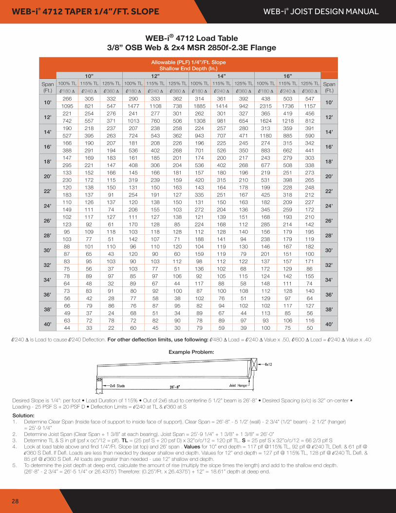
WEB-i® 4712 TAPER 1/4”/FT. SLOPE
Allowable (PLF) 1/4”/Ft. SlopeShallow End Depth (In.)
10” 12” 14” 16”Span(Ft.)
100% TL 115% TL 125% TL 100% TL 115% TL 125% TL 100% TL 115% TL 125% TL 100% TL 115% TL 125% TL Span(Ft.)l/180 ∆ l/240 ∆ l/360 ∆ l/180 ∆ l/240 ∆ l/360 ∆ l/180 ∆ l/240 ∆ l/360 ∆ l/180 ∆ l/240 ∆ l/360 ∆
10’266 305 332 290 333 362 314 361 392 438 503 547
10’1095 821 547 1477 1108 738 1885 1414 942 2315 1736 1157
12’221 254 276 241 277 301 262 301 327 365 419 456
12’742 557 371 1013 760 506 1308 981 654 1624 1218 812
14’190 218 237 207 238 258 224 257 280 313 359 391
14’527 395 263 724 543 362 943 707 471 1180 885 590
16’166 190 207 181 208 226 196 225 245 274 315 342
16’388 291 194 536 402 268 701 526 350 883 662 441
18’147 169 183 161 185 201 174 200 217 243 279 303
18’295 221 147 408 306 204 536 402 268 677 508 338
20’133 152 166 145 166 181 157 180 196 219 251 273
20’230 172 115 319 239 159 420 315 210 531 398 265
22’120 138 150 131 150 163 143 164 178 199 228 248
22’183 137 91 254 191 127 335 251 167 425 318 212
24’110 126 137 120 138 150 131 150 163 182 209 227
24’149 111 74 206 155 103 272 204 136 345 259 172
26’102 117 127 111 127 138 121 139 151 168 193 210
26’123 92 61 170 128 85 224 168 112 285 214 142
28’95 109 118 103 118 128 112 128 140 156 179 195
28’103 77 51 142 107 71 188 141 94 238 179 119
30’88 101 110 96 110 120 104 119 130 146 167 182
30’87 65 43 120 90 60 159 119 79 201 151 100
32’83 95 103 90 103 112 98 112 122 137 157 171
32’75 56 37 103 77 51 136 102 68 172 129 86
34’78 89 97 85 97 106 92 105 115 124 142 155
34’64 48 32 89 67 44 117 88 58 148 111 74
36’73 83 91 80 92 100 87 100 108 112 128 140
36’56 42 28 77 58 38 102 76 51 129 97 64
38’66 79 86 76 87 95 82 94 102 102 117 127
38’49 37 24 68 51 34 89 67 44 113 85 56
40’63 72 78 72 82 90 78 89 97 93 106 116
40’44 33 22 60 45 30 79 59 39 100 75 50
WEB-i® Tapered 4412 Load Table 3/8" OSB & 2x4 MSR 2100f-1.8E Flange
Allowable Load (PLF) 1/4"/Ft. Slope Shallow End Depths (In.)
10" 12" 14" 16"Span 100%TL 115%TL 125%TL 100%TL 115%TL 125%TL 100%TL 115%TL 125%TL 100%TL 115%TL 125%TL Span (Ft.) l/180 ∆ l/240 ∆ l/360 ∆ l/180 ∆ l/240 ∆ l/360 ∆ l/180 ∆ l/240 ∆ l/360 ∆ l/180 ∆ l/240 ∆ l/360 ∆ (Ft.)
266 305 332 290 333 362 314 361 392 438 503 547 10'932 699 466 1273 955 636 1643 1232 821 2038 1528 1019
10'
221 254 276 241 277 301 262 301 327 365 419 456 12'621 466 310 857 643 428 1118 838 559 1400 1050 700
12'
190 218 237 207 238 258 224 257 280 313 359 391 14'435 326 217 604 453 302 793 595 396 1000 750 500
14'
166 190 207 181 208 226 196 225 245 274 315 342 16'317 238 158 442 331 221 583 437 291 739 554 369
16'
147 169 183 161 185 201 174 200 217 243 279 303 18'239 179 119 334 250 167 441 331 220 561 421 280
18'
133 152 166 145 166 181 157 180 196 219 251 273 20'186 139 93 259 194 129 343 257 171 437 327 218
20'
120 138 150 131 150 163 143 164 178 188 216 235 22'147 110 73 205 154 102 272 204 136 347 260 173
22'
104 119 130 120 138 150 131 150 163 160 184 200 24'119 89 59 166 124 83 220 165 110 280 210 140
24'
90 103 112 106 121 132 121 139 151 138 158 172 26'98 73 49 137 102 68 181 135 90 230 173 115
26'
79 90 98 93 106 116 107 123 133 121 139 151 28'82 61 41 114 85 57 151 113 75 192 144 96
28'
70 80 87 82 94 102 94 108 117 106 121 132 30'69 52 34 96 72 48 127 95 63 162 121 81
30'
63 72 78 74 85 92 84 96 105 95 109 118 32'59 44 29 82 61 41 108 81 54 138 103 69
32'
57 65 71 66 75 82 75 86 93 85 97 106 34'51 38 25 71 53 35 93 70 46 119 89 59
34'
51 58 63 60 69 75 68 78 85 77 88 96 36'44 33 22 61 46 30 81 61 40 103 77 51
36'
47 54 58 54 62 67 62 71 77 69 79 86 38'39 29 19 54 40 27 71 53 35 90 67 45
38'
43 49 53 50 57 62 57 65 71 63 72 78 40'34 26 17 47 35 23 62 47 31 79 59 39
40'
l/240 ∆ is Load to cause l/240 Deflection For other deflection limits, use following: l/480 ∆ Load = l/240 ∆ Value x .50, l/600 ∆ Load = l/240 ∆ Value x .40 Example Problem:
Desired Slope is 1/4": per foot • Load Duration of 115% • Out of 2x6 stud to centerline 5 1/2" beam is 26'-8" • Desired Spacing (o/c) is 24" on-center • Loading - 25 PSF S + 20 PSF D • Deflection Limits = l/240 at TL & l/360 at S
Solution: 1. Determine Clear Span (Inside face of support to inside face of support). Clear Span = 26'-8" - 5 1/2' (wall) - 2 3/4" (1/2" beam) - 2 1/2" (hanger)
= 25'-9 1/4"2. Determine Joist Span (Clear Span + 1 3/8" at each bearing). Joist Span = 25'-9 1/4" + 1 3/8" + 1 3/8" = 26'-0"3. Determine TL & S in plf (psf x oc"/12 = plf). TL = (25 psf S + 20 psf D) x 24"o/c/12 = 90 plf TL. S = 25 psf S x 24"o/c/12 = 50 plf S4. Look at load table above and find 1/4"/Ft. Slope (at top) and 26' span . Values for 10" end depth = 103 plf @115% TL, 73 plf @ l/240 TL Defl. &
49 plf @ l/360 S Defl. If Defl. Loads are less than needed try deeper shallow end depth. Values for 12" end depth = 121 plf @ 115% TL, 102plf @ l/240 TL Defl. & 68 plf @ l/360 S Defl. All loads are greater than needed - use 12" shallow end depth.
5. To determine the joist depth at deep end, calculate the amount of rise (multiply the slope times the length) and add to the shallow end depth.(26'-8" - 2 3/4" = 26'-5 1/4" or 26.4375') Therefore: (0.25"/Ft. x 26.4375') + 12" = 18.61" depth at deep end.
Desired Slope is 1/4”: per foot • Load Duration of 115% • Out of 2x6 stud to centerline 5 1/2” beam is 26’-8” • Desired Spacing (o/c) is 32” on-center • Loading - 25 PSF S + 20 PSF D • Deflection Limits = l/240 at TL & l/360 at SSolution:1 . Determine Clear Span (Inside face of support to inside face of support). Clear Span = 26’-8” - 5 1/2’ (wall) - 2 3/4” (1/2” beam) - 2 1/2” (hanger)
= 25’-9 1/4”2 . Determine Joist Span (Clear Span + 1 3/8” at each bearing). Joist Span = 25’-9 1/4” + 1 3/8” + 1 3/8” = 26’-0” 3 . Determine TL & S in plf (psf x oc”/12 = plf). TL = (25 psf S + 20 psf D) x 32”o/c/12 = 120 plf TL. S = 25 psf S x 32”o/c/12 = 66 2/3 plf S4 . Look at load table above and find 1/4”/Ft. Slope (at top) and 26’ span . Values for 10” end depth = 117 plf @115% TL, 92 plf @ l/240 TL Defl. & 61 plf @
l/360 S Defl. If Defl. Loads are less than needed try deeper shallow end depth. Values for 12” end depth = 127 plf @ 115% TL, 128 plf @ l/240 TL Defl. & 85 plf @ l/360 S Defl. All loads are greater than needed - use 12” shallow end depth.
5 . To determine the joist depth at deep end, calculate the amount of rise (multiply the slope times the length) and add to the shallow end depth. (26’-8” - 2 3/4” = 26’-5 1/4” or 26.4375’) Therefore: (0.25”/Ft. x 26.4375’) + 12” = 18.61” depth at deep end.
WEB-i® 4712 Load Table3/8” OSB Web & 2x4 MSR 2850f-2.3E Flange
l/240 ∆ is Load to cause l/240 Deflection. For other deflection limits, use following: l/480 ∆ Load = l/240 ∆ Value x .50, l/600 ∆ Load = l/240 ∆ Value x .40
Example Problem:

WEB-i® JOIST DESIGN MANUAL
29
WEB-i® 4712 TAPER 3/8”/FT. SLOPE
Allowable (PLF) 3/8”/Ft. SlopeShallow End Depth (In.)
10” 12” 14” 16”Span(Ft.)
100% TL 115% TL 125% TL 100% TL 115% TL 125% TL 100% TL 115% TL 125% TL 100% TL 115% TL 125% TL Span(Ft.)l/180 ∆ l/240 ∆ l/360 ∆ l/180 ∆ l/240 ∆ l/360 ∆ l/180 ∆ l/240 ∆ l/360 ∆ l/180 ∆ l/240 ∆ l/360 ∆
10’266 305 332 290 333 362 314 361 392 438 503 547
10’1194 895 597 1586 1189 793 2003 1502 1001 2440 1830 1220
12’221 254 276 241 277 301 262 301 327 365 419 456
12’823 617 411 1105 829 552 1410 1057 705 1733 1300 866
14’190 218 237 207 238 258 224 257 280 313 359 391
14’593 445 296 802 601 401 1029 772 514 1274 956 637
16’166 190 207 181 208 226 196 225 245 274 315 342
16’444 333 222 601 451 300 776 582 388 964 723 482
18’147 169 183 161 185 201 174 200 217 243 279 303
18’342 256 171 464 348 232 600 450 300 748 561 374
20’133 152 166 145 166 181 157 180 196 219 251 273
20’270 202 135 366 275 183 475 356 237 593 445 296
22’120 138 150 131 150 163 143 164 178 199 228 248
22’217 163 108 295 221 147 383 287 191 479 359 239
24’110 126 137 120 138 150 131 150 163 182 209 227
24’178 134 89 242 182 121 314 235 157 393 295 196
26’102 117 127 111 127 138 121 139 151 168 193 210
26’149 111 74 202 151 101 261 196 130 327 245 163
28’95 109 118 103 118 128 112 128 140 156 179 195
28’126 94 63 170 127 85 220 165 110 276 207 138
30’88 101 110 96 110 120 104 119 130 146 167 182
30’107 80 53 145 109 72 188 141 94 235 176 117
32’83 95 103 90 103 112 98 112 122 137 157 171
32’93 69 46 125 94 62 162 121 81 202 152 101
34’78 89 97 85 97 106 92 105 115 129 148 161
34’81 60 40 109 81 54 141 105 70 176 132 88
36’73 83 91 80 92 100 87 100 108 121 139 151
36’71 53 35 95 71 47 123 92 61 154 115 77
38’70 80 87 76 87 95 82 94 102 113 129 141
38’63 47 31 84 63 42 109 81 54 135 101 67
40’66 75 82 72 82 90 78 89 97 103 118 128
40’56 42 28 75 56 37 96 72 48 120 90 60
WEB-i® Tapered 4412 Load Table 3/8" OSB & 2x4 MSR 2100f-1.8E Flange
Allowable Load (PLF) 1/4"/Ft. Slope Shallow End Depths (In.)
10" 12" 14" 16"Span 100%TL 115%TL 125%TL 100%TL 115%TL 125%TL 100%TL 115%TL 125%TL 100%TL 115%TL 125%TL Span (Ft.) l/180 ∆ l/240 ∆ l/360 ∆ l/180 ∆ l/240 ∆ l/360 ∆ l/180 ∆ l/240 ∆ l/360 ∆ l/180 ∆ l/240 ∆ l/360 ∆ (Ft.)
266 305 332 290 333 362 314 361 392 438 503 547 10'932 699 466 1273 955 636 1643 1232 821 2038 1528 1019
10'
221 254 276 241 277 301 262 301 327 365 419 456 12'621 466 310 857 643 428 1118 838 559 1400 1050 700
12'
190 218 237 207 238 258 224 257 280 313 359 391 14'435 326 217 604 453 302 793 595 396 1000 750 500
14'
166 190 207 181 208 226 196 225 245 274 315 342 16'317 238 158 442 331 221 583 437 291 739 554 369
16'
147 169 183 161 185 201 174 200 217 243 279 303 18'239 179 119 334 250 167 441 331 220 561 421 280
18'
133 152 166 145 166 181 157 180 196 219 251 273 20'186 139 93 259 194 129 343 257 171 437 327 218
20'
120 138 150 131 150 163 143 164 178 188 216 235 22'147 110 73 205 154 102 272 204 136 347 260 173
22'
104 119 130 120 138 150 131 150 163 160 184 200 24'119 89 59 166 124 83 220 165 110 280 210 140
24'
90 103 112 106 121 132 121 139 151 138 158 172 26'98 73 49 137 102 68 181 135 90 230 173 115
26'
79 90 98 93 106 116 107 123 133 121 139 151 28'82 61 41 114 85 57 151 113 75 192 144 96
28'
70 80 87 82 94 102 94 108 117 106 121 132 30'69 52 34 96 72 48 127 95 63 162 121 81
30'
63 72 78 74 85 92 84 96 105 95 109 118 32'59 44 29 82 61 41 108 81 54 138 103 69
32'
57 65 71 66 75 82 75 86 93 85 97 106 34'51 38 25 71 53 35 93 70 46 119 89 59
34'
51 58 63 60 69 75 68 78 85 77 88 96 36'44 33 22 61 46 30 81 61 40 103 77 51
36'
47 54 58 54 62 67 62 71 77 69 79 86 38'39 29 19 54 40 27 71 53 35 90 67 45
38'
43 49 53 50 57 62 57 65 71 63 72 78 40'34 26 17 47 35 23 62 47 31 79 59 39
40'
l/240 ∆ is Load to cause l/240 Deflection For other deflection limits, use following: l/480 ∆ Load = l/240 ∆ Value x .50, l/600 ∆ Load = l/240 ∆ Value x .40 Example Problem:
Desired Slope is 1/4": per foot • Load Duration of 115% • Out of 2x6 stud to centerline 5 1/2" beam is 26'-8" • Desired Spacing (o/c) is 24" on-center • Loading - 25 PSF S + 20 PSF D • Deflection Limits = l/240 at TL & l/360 at S
Solution: 1. Determine Clear Span (Inside face of support to inside face of support). Clear Span = 26'-8" - 5 1/2' (wall) - 2 3/4" (1/2" beam) - 2 1/2" (hanger)
= 25'-9 1/4"2. Determine Joist Span (Clear Span + 1 3/8" at each bearing). Joist Span = 25'-9 1/4" + 1 3/8" + 1 3/8" = 26'-0"3. Determine TL & S in plf (psf x oc"/12 = plf). TL = (25 psf S + 20 psf D) x 24"o/c/12 = 90 plf TL. S = 25 psf S x 24"o/c/12 = 50 plf S4. Look at load table above and find 1/4"/Ft. Slope (at top) and 26' span . Values for 10" end depth = 103 plf @115% TL, 73 plf @ l/240 TL Defl. &
49 plf @ l/360 S Defl. If Defl. Loads are less than needed try deeper shallow end depth. Values for 12" end depth = 121 plf @ 115% TL, 102plf @ l/240 TL Defl. & 68 plf @ l/360 S Defl. All loads are greater than needed - use 12" shallow end depth.
5. To determine the joist depth at deep end, calculate the amount of rise (multiply the slope times the length) and add to the shallow end depth.(26'-8" - 2 3/4" = 26'-5 1/4" or 26.4375') Therefore: (0.25"/Ft. x 26.4375') + 12" = 18.61" depth at deep end.
Desired Slope is 3/8”: per foot • Load Duration of 115% • Out of 2x6 stud to centerline 5 1/2” beam is 26’-8” • Desired Spacing (o/c) is 32” on-center • Loading - 25 PSF S + 20 PSF D • Deflection Limits = l/240 at TL & l/360 at SSolution:1 . Determine Clear Span (Inside face of support to inside face of support). Clear Span = 26’-8” - 5 1/2’ (wall) - 2 3/4” (1/2” beam) - 2 1/2” (hanger)
= 25’-9 1/4”2 . Determine Joist Span (Clear Span + 1 3/8” at each bearing). Joist Span = 25’-9 1/4” + 1 3/8” + 1 3/8” = 26’-0” 3 . Determine TL & S in plf (psf x oc”/12 = plf). TL = (25 psf S + 20 psf D) x 32”o/c/12 = 120 plf TL. S = 25 psf S x 32”o/c/12 = 66 2/3 plf S4 . Look at load table above and find 3/8”/Ft. Slope (at top) and 26’ span . Values for 10” end depth = 117 plf @115% TL, 111 plf @ l/240 TL Defl. & 74 plf @
l/360 S Defl. If Defl. Loads are less than needed try deeper shallow end depth. Values for 12” end depth = 127 plf @ 115% TL, 151 plf @ l/240 TL Defl. & 101 plf @ l/360 S Defl. All loads are greater than needed - use 12” shallow end depth.
5 . To determine the joist depth at deep end, calculate the amount of rise (multiply the slope times the length) and add to the shallow end depth. (26’-8” - 2 3/4” = 26’-5 1/4” or 26.4375’) Therefore: (0.375”/Ft. x 26.4375’) + 12” = 21.91” depth at deep end.
WEB-i® 4712 Load Table3/8” OSB Web & 2x4 MSR 2850f-2.3E Flange
l/240 ∆ is Load to cause l/240 Deflection. For other deflection limits, use following: l/480 ∆ Load = l/240 ∆ Value x .50, l/600 ∆ Load = l/240 ∆ Value x .40
Example Problem:

WEB-i® JOIST DESIGN MANUALNOTES


02-2017
We further guarantee that our Open Web andWeb-i® products, when correctly used andinstalled, will meet or exceed our specificationsas set forth in our ICC-ES Report ESR-2974for the natural life of the structure.
Kevin SweetPresidentWeb Joist Northwest Corp .