weatherization standards and field guide for pennsylvania
TRANSCRIPT

Copyright 2010 • Saturn Resource Management, Inc. • Helena, MT
Weatherization Standards and Field Guide for Pennsylvania
February 2011 EditionPublished for the
Department of Energy Weatherization Assistance Program
and the
Pennsylvania Department of Community, Economic Development, and Office of Energy Conservation and
Weatherization
Technical Reviewers:Dominick Amato
John “Kirk” GennettTimothy GoffTony Kimmel
John ManzHank Wierzbicki
Technical Contributors:
Larry ArmandaMichael Blasnik
R. W. DavisPam Denlinger
Chris DorsiHap HavenRich Karg
Rudy LeathermanBruce Manclark
Rich MooreGary Nelson
Tamasin SternerKen Tohinaka
Principle Authors: John Krigger and Bill Van der MeerIllustrated by John Krigger, Bob Starkey, and Alice Hyvonen
The Weatherization Training CenterPennsylvania College of Technology
One College Avenue • Williamsport, PA 17701Phone 570-327-4768 • Fax 570-320-5239
www.pct.edu/wtc

Foreword
ForewordThe Weatherization Standards and Field Guide for Pennsylvania is designed to provide direction and guidance to staff and man-agement of the Commonwealth of Pennsylvania’s Weatheriza-tion Assistance Program (PAWAP). The program administrator, Department of Community and Economic Development (DCED) provides these standards and field guide for use by its weatherization agencies and private contractors. This manual results from a partnership between DCED, the US Department of Energy Weatherization Assistance Program (DOEWAP), and Saturn Resource Management Inc.
The first chapter, titled Pennsylvania Weatherization Standards outlines the DCED technical program requirements for Penn-sylvania’s weatherization agencies. The subsequent chapters comprise the Field Guide and covers suggested technical proce-dures and standards for energy auditors and technicians.
Weatherization is a collection of procedures designed to reduce energy consumption, increase comfort, improve durability, and enhance health and safety for its clients. Weatherization expen-ditures are justified primarily by money saved by low-income families in energy expenses. The Department of Energy and State Governments issue requirements for how to spend tax dol-lars on weatherization cost-effectively. PAWAP now uses prior-ity lists for ensuring the cost-effectiveness of weatherization. These priority lists, presented in the first chapter, were gener-ated by computer analysis of typical Pennsylvania homes, using the National Home Energy Audit (NEAT) and the Manufac-tured House Energy Audit (MHEA).
This guidebook is designed to be a changeable and constantly improving document. Your comments, questions, and construc-tive criticism will be important to its future.

Tab
le o
fC
onte
nts
Weatherization Field Guide for Pennsylvania 7
TABLE OF CONTENTS
PA Weatherization Standards 13
General Standards . . . . . . . . . . . . . . . . . . . . . . . . . . . . . . . . . . . . . 13Materials for Measures . . . . . . . . . . . . . . . . . . . . . . . . . . . . . . . 13Energy Audit . . . . . . . . . . . . . . . . . . . . . . . . . . . . . . . . . . . . . . . 13Client Education . . . . . . . . . . . . . . . . . . . . . . . . . . . . . . . . . . . . 14Air-Leakage Testing . . . . . . . . . . . . . . . . . . . . . . . . . . . . . . . . . 14Zonal Pressure Diagnostics and Pressure Pan Testing . . . . 15Priority Lists for Measure Selection . . . . . . . . . . . . . . . . . . . . 16
Single Family Home Standards . . . . . . . . . . . . . . . . . . . . . . . . . . 20Conditioned Versus Unconditioned Basements. . . . . . . . . . 20Closed Cavity Dense Pack Insulation . . . . . . . . . . . . . . . . . . . 21Window and Door Replacement. . . . . . . . . . . . . . . . . . . . . . . 21
Manufactured House Standards . . . . . . . . . . . . . . . . . . . . . . . . . 22Building Repairs. . . . . . . . . . . . . . . . . . . . . . . . . . . . . . . . . . . . . 23
Heating-System Standards . . . . . . . . . . . . . . . . . . . . . . . . . . . . . . 23Heating Systems Testing. . . . . . . . . . . . . . . . . . . . . . . . . . . . . . 23
Baseload Energy Standards . . . . . . . . . . . . . . . . . . . . . . . . . . . . . 26Administrative Issues . . . . . . . . . . . . . . . . . . . . . . . . . . . . . . . . . . 27
Incorporating Baseload Measures into Job Costs . . . . . . . . . 27Health and Safety Standards . . . . . . . . . . . . . . . . . . . . . . . . . . . . 28
Crew or Contractor Health and Safety . . . . . . . . . . . . . . . . . . 28Client Health and Safety . . . . . . . . . . . . . . . . . . . . . . . . . . . . . . 29Moisture Problems . . . . . . . . . . . . . . . . . . . . . . . . . . . . . . . . . . 30Mold . . . . . . . . . . . . . . . . . . . . . . . . . . . . . . . . . . . . . . . . . . . . . . 30Severe Indoor Air Quality Problems. . . . . . . . . . . . . . . . . . . . 31Building Airflow Standard (BAS) . . . . . . . . . . . . . . . . . . . . . . 31Lead-Based Paint Hazards . . . . . . . . . . . . . . . . . . . . . . . . . . . . 32
Other Health and Safety Issues . . . . . . . . . . . . . . . . . . . . . . . . . . 33Deferral of Weatherization Services . . . . . . . . . . . . . . . . . . . . . . 34Final Inspection . . . . . . . . . . . . . . . . . . . . . . . . . . . . . . . . . . . . . . . 35
Tab
le o
fC
onte
nts
Table of Contents8
Auditing, Education, Baseload and Hot Water Savings 37
Understanding energy usage . . . . . . . . . . . . . . . . . . . . . . . . . . . . 38Weatherization work flow . . . . . . . . . . . . . . . . . . . . . . . . . . . . . . 40Client education. . . . . . . . . . . . . . . . . . . . . . . . . . . . . . . . . . . . . . . 42
Education hand-in-hand with other WAP treatments . . . . 42Reducing heating costs . . . . . . . . . . . . . . . . . . . . . . . . . . . . . . . 45Hydronic heating systems . . . . . . . . . . . . . . . . . . . . . . . . . . . . 45Hot-water and laundry savings . . . . . . . . . . . . . . . . . . . . . . . . 46Staying cool during hot weather . . . . . . . . . . . . . . . . . . . . . . . 47Other energy-saving opportunities . . . . . . . . . . . . . . . . . . . . . 48
Assessing baseload energy-saving opportunities . . . . . . . . . . . 49Refrigerator Replacement. . . . . . . . . . . . . . . . . . . . . . . . . . . . . . . 50
Refrigerator Testing Criteria . . . . . . . . . . . . . . . . . . . . . . . . . . 50Refrigerator Testing Methodology . . . . . . . . . . . . . . . . . . . . . 50Waivers, Warranties, Release of Accountability . . . . . . . . . . 50Disposal of Refrigerators . . . . . . . . . . . . . . . . . . . . . . . . . . . . . 52Refrigerator Maintenance Energy Education Topics . . . . . . 52
Energy Efficient Lighting . . . . . . . . . . . . . . . . . . . . . . . . . . . . . . . 54Compact Fluorescent Lamp (CFL) Replacement . . . . . . . . . 54Halogen Lamps . . . . . . . . . . . . . . . . . . . . . . . . . . . . . . . . . . . . . 56
Clothes Dryer Improvements . . . . . . . . . . . . . . . . . . . . . . . . . . . 56Water Heating Measures . . . . . . . . . . . . . . . . . . . . . . . . . . . . . . . 57
Water-heaters. . . . . . . . . . . . . . . . . . . . . . . . . . . . . . . . . . . . . . . 58Water heating energy retrofits . . . . . . . . . . . . . . . . . . . . . . . . . 60
Other Baseload Use . . . . . . . . . . . . . . . . . . . . . . . . . . . . . . . . . . . . 62
Health and Safety Information 63
Client health and safety. . . . . . . . . . . . . . . . . . . . . . . . . . . . . . . . . 63Carbon monoxide . . . . . . . . . . . . . . . . . . . . . . . . . . . . . . . . . . . 64Gas range and oven safety . . . . . . . . . . . . . . . . . . . . . . . . . . . . 66Moisture problems . . . . . . . . . . . . . . . . . . . . . . . . . . . . . . . . . . 67Lead-safe weatherization . . . . . . . . . . . . . . . . . . . . . . . . . . . . . 76

Tab
le o
fC
onte
nts
Weatherization Field Guide for Pennsylvania 9
Worker health and safety . . . . . . . . . . . . . . . . . . . . . . . . . . . . . . . 77Commitment to safety . . . . . . . . . . . . . . . . . . . . . . . . . . . . . . . 78Driving . . . . . . . . . . . . . . . . . . . . . . . . . . . . . . . . . . . . . . . . . . . . 79New employees . . . . . . . . . . . . . . . . . . . . . . . . . . . . . . . . . . . . . 79Lifting and back injuries . . . . . . . . . . . . . . . . . . . . . . . . . . . . . . 80Respiratory health . . . . . . . . . . . . . . . . . . . . . . . . . . . . . . . . . . . 81Hazardous materials . . . . . . . . . . . . . . . . . . . . . . . . . . . . . . . . . 82Falls . . . . . . . . . . . . . . . . . . . . . . . . . . . . . . . . . . . . . . . . . . . . . . . 83Repetitive Stress Injuries. . . . . . . . . . . . . . . . . . . . . . . . . . . . . . 84Tool safety. . . . . . . . . . . . . . . . . . . . . . . . . . . . . . . . . . . . . . . . . . 84
Heating System Specifications 87
Combustion safety and efficiency testing. . . . . . . . . . . . . . . . . . 88Gas burner safety and efficiency testing. . . . . . . . . . . . . . . . . 88Leak-testing gas piping . . . . . . . . . . . . . . . . . . . . . . . . . . . . . . . 94Oil-burner safety and efficiency . . . . . . . . . . . . . . . . . . . . . . . 94
Measuring draft and house pressures . . . . . . . . . . . . . . . . . . . . 100Draft characteristics in combustion appliances . . . . . . . . . 101Worst-case combustion appliance zone tests . . . . . . . . . . . 102CAZ Combustion Safety Test . . . . . . . . . . . . . . . . . . . . . . . . 103* Protocol for Draft Testing . . . . . . . . . . . . . . . . . . . . . . . . . . 107Improving inadequate draft . . . . . . . . . . . . . . . . . . . . . . . . . . 108
Venting combustion gases . . . . . . . . . . . . . . . . . . . . . . . . . . . . . 109General venting requirements . . . . . . . . . . . . . . . . . . . . . . . . 109Vent connectors. . . . . . . . . . . . . . . . . . . . . . . . . . . . . . . . . . . . 110Chimneys . . . . . . . . . . . . . . . . . . . . . . . . . . . . . . . . . . . . . . . . . 113Special venting considerations for gas . . . . . . . . . . . . . . . . . 117Manufactured House furnace venting . . . . . . . . . . . . . . . . . 123Wood-heating venting and safety . . . . . . . . . . . . . . . . . . . . . 124
Combustion air . . . . . . . . . . . . . . . . . . . . . . . . . . . . . . . . . . . . . . 126Un-confined-space combustion air . . . . . . . . . . . . . . . . . . . 127Confined-space combustion air . . . . . . . . . . . . . . . . . . . . . . 128Proprietary combustion-air systems. . . . . . . . . . . . . . . . . . . 130
Tab
le o
fC
onte
nts
Table of Contents10
Forced-air system standards . . . . . . . . . . . . . . . . . . . . . . . . . . . 131Inspecting furnace heat exchangers . . . . . . . . . . . . . . . . . . . 132Furnace operating standards . . . . . . . . . . . . . . . . . . . . . . . . . 133Duct air-tightness standards . . . . . . . . . . . . . . . . . . . . . . . . . 135Duct insulation. . . . . . . . . . . . . . . . . . . . . . . . . . . . . . . . . . . . . 138Improving duct-system airflow . . . . . . . . . . . . . . . . . . . . . . . 139
Heating-system replacement specifications. . . . . . . . . . . . . . . 142Furnace replacement. . . . . . . . . . . . . . . . . . . . . . . . . . . . . . . . 144Oil-fired heating installation . . . . . . . . . . . . . . . . . . . . . . . . . 146Gas-fired heating installation. . . . . . . . . . . . . . . . . . . . . . . . . 148Electric-furnaces and electric baseboard heat . . . . . . . . . . . 149
Hot-water and steam standards. . . . . . . . . . . . . . . . . . . . . . . . . 149Boiler efficiency and maintenance . . . . . . . . . . . . . . . . . . . . 149Hot-water space-heating . . . . . . . . . . . . . . . . . . . . . . . . . . . . 151Steam heating . . . . . . . . . . . . . . . . . . . . . . . . . . . . . . . . . . . . . . 153Boiler replacement. . . . . . . . . . . . . . . . . . . . . . . . . . . . . . . . . . 156
Air-Sealing and Insulating 161
Reducing air leakage . . . . . . . . . . . . . . . . . . . . . . . . . . . . . . . . . . 161When not to air seal . . . . . . . . . . . . . . . . . . . . . . . . . . . . . . . . 162Sealing bypasses . . . . . . . . . . . . . . . . . . . . . . . . . . . . . . . . . . . . 163Minor air sealing . . . . . . . . . . . . . . . . . . . . . . . . . . . . . . . . . . . 169
Installing insulation. . . . . . . . . . . . . . . . . . . . . . . . . . . . . . . . . . . 169Electrical safety. . . . . . . . . . . . . . . . . . . . . . . . . . . . . . . . . . . . . 170Attic insulation. . . . . . . . . . . . . . . . . . . . . . . . . . . . . . . . . . . . . 172Attic venting . . . . . . . . . . . . . . . . . . . . . . . . . . . . . . . . . . . . . . . 175Blowing attic insulation . . . . . . . . . . . . . . . . . . . . . . . . . . . . . 176Installing batt insulation. . . . . . . . . . . . . . . . . . . . . . . . . . . . . 176Finished attics of 11/2-story homes . . . . . . . . . . . . . . . . . . . . 177Walk-up stairway and door . . . . . . . . . . . . . . . . . . . . . . . . . . 179Air sealing and insulating row house attics . . . . . . . . . . . . . 181Wall insulation. . . . . . . . . . . . . . . . . . . . . . . . . . . . . . . . . . . . . 187Floor insulation . . . . . . . . . . . . . . . . . . . . . . . . . . . . . . . . . . . . 194

Tab
le o
fC
onte
nts
Weatherization Field Guide for Pennsylvania 11
Diagnosing Shell & Duct Air Leakage 199
House airtightness testing . . . . . . . . . . . . . . . . . . . . . . . . . . . . . 201Blower-door testing. . . . . . . . . . . . . . . . . . . . . . . . . . . . . . . . . . . 202
Measuring pressure and airflow . . . . . . . . . . . . . . . . . . . . . . 203Preparing for a blower door test . . . . . . . . . . . . . . . . . . . . . . 205Blower Door Test Procedures . . . . . . . . . . . . . . . . . . . . . . . . 206Building Airflow Standard (BAS) . . . . . . . . . . . . . . . . . . . . . 211
Zonal pressure diagnostics . . . . . . . . . . . . . . . . . . . . . . . . . . . . . 211Primary versus secondary air barriers . . . . . . . . . . . . . . . . . 213Very simple pressure tests . . . . . . . . . . . . . . . . . . . . . . . . . . . 214Using a manometer to test air barriers . . . . . . . . . . . . . . . . . 215Zonal pressure diagnostic methods . . . . . . . . . . . . . . . . . . . 216Zone pressures, air sealing, and insulation . . . . . . . . . . . . . 219
Duct airtightness testing. . . . . . . . . . . . . . . . . . . . . . . . . . . . . . . 221Pressure-pan testing . . . . . . . . . . . . . . . . . . . . . . . . . . . . . . . . 221
Duct-induced pressures . . . . . . . . . . . . . . . . . . . . . . . . . . . . . . . 223Measuring duct-induced pressures . . . . . . . . . . . . . . . . . . . . 223
Manufactured Housing Specifications 227
Manufactured house heating . . . . . . . . . . . . . . . . . . . . . . . . . . . 228Furnace maintenance and energy efficiency . . . . . . . . . . . . 230Heating appliance replacement . . . . . . . . . . . . . . . . . . . . . . . 230
Manufactured house air sealing. . . . . . . . . . . . . . . . . . . . . . . . . 231Air-leakage locations. . . . . . . . . . . . . . . . . . . . . . . . . . . . . . . . 231Duct-leak locations . . . . . . . . . . . . . . . . . . . . . . . . . . . . . . . . . 232
Manufactured house insulation. . . . . . . . . . . . . . . . . . . . . . . . . 235Blowing manufactured house roof cavities . . . . . . . . . . . . . 235Manufactured house floor insulation . . . . . . . . . . . . . . . . . . 239
Manufactured house windows and doors . . . . . . . . . . . . . . . . 241Manufactured house storm windows . . . . . . . . . . . . . . . . . . 241Replacing manufactured house windows. . . . . . . . . . . . . . . 242Manufactured house doors . . . . . . . . . . . . . . . . . . . . . . . . . . 242Manufactured house health and safety. . . . . . . . . . . . . . . . . 243
Tab
le o
fC
onte
nts
Table of Contents12
Appendices . . . . . . . . . . . . . . . . . . . . . . . . . . . . . . . . . . . . . . . . . . 245Baseload Auditing Tools and Equipment . . . . . . . . . . . . . . 247Air Sealing and Insulating Tools . . . . . . . . . . . . . . . . . . . . . . 248Auditing and Mechanical Tools . . . . . . . . . . . . . . . . . . . . . . 249Weatherization Materials and Inventory . . . . . . . . . . . . . . . 250Approximate R-values for Construction Materials . . . . . . 251Comparison of Various Units of Pressure . . . . . . . . . . . . . . 252Efficiency Table for # 2 Fuel Oil . . . . . . . . . . . . . . . . . . . . . . 253Efficiency Table for Natural Gas . . . . . . . . . . . . . . . . . . . . . . 254Resources . . . . . . . . . . . . . . . . . . . . . . . . . . . . . . . . . . . . . . . . . 255
Weatherization Glossary . . . . . . . . . . . . . . . . . . . . . . . . . . . . . . 257Tables and Illustrations. . . . . . . . . . . . . . . . . . . . . . . . . . . . . . . . 291Index . . . . . . . . . . . . . . . . . . . . . . . . . . . . . . . . . . . . . . . . . . . . . . . 297
PA W
x St
and
ard
s
Weatherization Field Guide for Pennsylvania 13
PA WEATHERIZATION STANDARDS
The purpose of this chapter of the Weatherization Standards and Field Guide for Pennsylvania is to summarize the standards neces-sary for a local weatherization agency to correctly execute the Pennsylvania State Weatherization Plan. The state plan is an agreement among the United States Department of Energy (DOE), PA (DCED), and the local weatherization agencies. Stan-dards are guidance to agency management about the minimum technical program requirements of the PAWAP and are confined to the first chapter. The remainder of the book is devoted to pro-cedures, to be used by agency subcontractors and energy auditors in executing field based weatherization activities.
GENERAL STANDARDS
The purpose of general standards is to standardize the provision of services and the documentation that provides proof that funds were spent according to good practice.
Materials for Measures
Weatherization materials, installed under the PAWAP, must con-form to the specifications and standards as referenced in Appen-dix A of 10 CFR, Part 440. Installation of all materials must be in a professional and workmanlike manner according to industry accepted practices or manufacturer specifications.
Insulation may only be purchased from companies who are on the DCED list of approved manufacturers.
Energy Audit
Each dwelling must receive a site-specific energy audit, following the approved Weatherization Priority Lists. Measures that have been identified in the priority list have been proven to have a sav-ings-to-investment ratio (SIR) greater than one (1). The installa-

PA W
x St
and
ard
s
PA Weatherization Standards14
tion of these measures is considered adequate weatherization practice.
Each energy audit will include a blower-door test, a heating-sys-tem assessment, a baseload audit, a health-and-safety evaluation and recommended building shell air sealing and insulation ret-rofits.
In the process of conducting an audit, the auditor should make every attempt to determine how the home is being used and define the actual thermal boundary. The thermal boundary is made up of all the surface or building components that separate heated from unheated spaces. An example would be an attic staircase where the sidewalls, staircase ceiling, and door are part of the thermal boundary. For additional guidance see “Air-Seal-ing and Insulating” on page 161.
Document the energy audit in the client file. At a minimum, the client file must include the required information on the DCED-approved audit protocol. Digital photographs needed to justify work scope are required.
Client Education
Clients can enhance weatherization efforts by developing good habits for using energy wisely. Client education must be pro-vided to every client as part of weatherization services. See “Cli-ent education” on page 42.
Air-Leakage Testing
All dwelling units must have blower door tests performed before, during, and after a weatherization retrofit. Its purpose is to help locate air leakage and to monitor the level of air tightness resulting from air sealing and insulating the building shell.
The minimum blower door generated value to be obtained and documented in the client file is air flow in cubic feet of air per minute at a house pressure difference of 50 pascals (cfm50).
PA W
x St
and
ard
s
Weatherization Field Guide for Pennsylvania 15
A blower door test is required for estimating air flow (cfm50). These may be obtained from the blower door gauges, manufac-turer provided calibration charts (CRF-50) or software.
Technicians may perform as many blower door tests as they feel necessary to monitor the progress of their air sealing work. This is recommended. However, the auditor must perform and docu-ment a minimum of one “Pre Test” and one “Post Test” in the client file. On rare occasions a blower door test may not be possi-ble. Documentation of the reasons why a blower door test was not performed must be provided in the client file.
Zonal Pressure Diagnostics and Pressure Pan Testing
Other types of blower door techniques such as zonal pressure diagnostics to detect air leakage pathways and pressure-pan test-ing to help find duct leakage are used to detect hidden air leaks quickly.
Zonal Pressure Diagnostics on all homes and Pressure Pan Testing on warm air systems are required as routine test procedures. These tests should be repeated in cases where post blower door test results show less than expected air leakage reductions and fur-ther investigation by using these procedures is necessary.
Zonal tests may be performed on interior wall cavities, tuck under garage ceilings, cantilevered ceilings, knee wall attics, vented crawl spaces etc. Where applicable, agencies should perform zonal tests on the basement and attic spaces.
The necessary equipment to perform these tests include the blower door, digital manometer, smoke generating device and pressure pan. Agencies must have this equipment available to be able to perform these tests when necessary. See “Using a manome-ter to test air barriers” on page 215. See “Pressure-pan testing” on page 221.
PA W
x St
and
ard
s
PA Weatherization Standards16
Priority Lists for Measure Selection
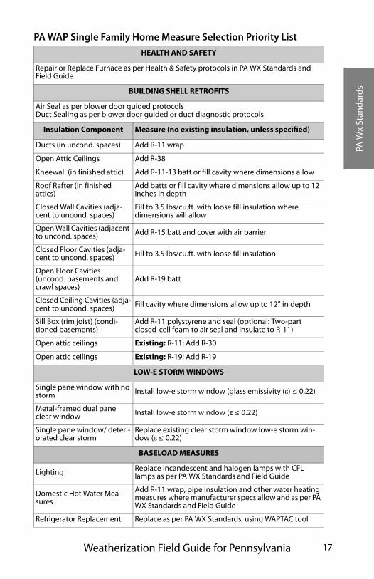
A priority list for measure selection must be used to select mea-sures to install in homes. The priority lists are based on the National Home Energy Audit (NEAT) and the manufactured House Energy Audit (MHEA), which are accepted methods of determining the cost-effectiveness of weatherization measures. the Single-Family Home Measure Selection Priority List dictates measure selection in single-family homes. The Manufactured house Measure Selection Priority List dictates measure selection for manufactured houses. In both priority lists, measures con-tained within the categories of building shell, mechanical and baseload retrofits are listed in order of priority, according to their cost-effectiveness.
Weatherization agencies must install measures higher on the list before measures lower on the list. The procedure is to budget funds for as many high-priority measures as possible, working from the top of the list to the bottom. Not following the Priority List measures is unacceptable, except when serious unsolvable problems prevent their installation. Serious unsolvable prob-lems are health, safety, and building-durability problems that cannot be solved within the scope of weatherization.
Agencies must develop in-house technical know how, and pur-chase the proper equipment to be able to effectively install mea-sures such as dense pack insulation in areas such as wooden framed sidewalls or manufactured house bellies and ceilings.
PA W
x St
and
ard
s
Weatherization Field Guide for Pennsylvania 17
PA WAP Single Family Home Measure Selection Priority List
HEALTH AND SAFETY
Repair or Replace Furnace as per Health & Safety protocols in PA WX Standards and Field Guide
BUILDING SHELL RETROFITS
Air Seal as per blower door guided protocolsDuct Sealing as per blower door guided or duct diagnostic protocols
Insulation Component Measure (no existing insulation, unless specified)
Ducts (in uncond. spaces) Add R-11 wrap
Open Attic Ceilings Add R-38
Kneewall (in finished attic) Add R-11-13 batt or fill cavity where dimensions allow
Roof Rafter (in finished attics)
Add batts or fill cavity where dimensions allow up to 12 inches in depth
Closed Wall Cavities (adja-cent to uncond. spaces)
Fill to 3.5 lbs/cu.ft. with loose fill insulation where dimensions will allow
Open Wall Cavities (adjacent to uncond. spaces) Add R-15 batt and cover with air barrier
Closed Floor Cavities (adja-cent to uncond. spaces) Fill to 3.5 lbs/cu.ft. with loose fill insulation
Open Floor Cavities (uncond. basements and crawl spaces)
Add R-19 batt
Closed Ceiling Cavities (adja-cent to uncond. spaces) Fill cavity where dimensions allow up to 12” in depth
Sill Box (rim joist) (condi-tioned basements)
Add R-11 polystyrene and seal (optional: Two-part closed-cell foam to air seal and insulate to R-11)
Open attic ceilings Existing: R-11; Add R-30
Open attic ceilings Existing: R-19; Add R-19
LOW-E STORM WINDOWS
Single pane window with no storm Install low-e storm window (glass emissivity (ε) ≤ 0.22)
Metal-framed dual pane clear window Install low-e storm window (ε ≤ 0.22)
Single pane window/ deteri-orated clear storm
Replace existing clear storm window low-e storm win-dow (ε ≤ 0.22)
BASELOAD MEASURES
Lighting Replace incandescent and halogen lamps with CFL lamps as per PA WX Standards and Field Guide
Domestic Hot Water Mea-sures
Add R-11 wrap, pipe insulation and other water heating measures where manufacturer specs allow and as per PA WX Standards and Field Guide
Refrigerator Replacement Replace as per PA WX Standards, using WAPTAC tool
PA W
x St
and
ard
s
PA Weatherization Standards18
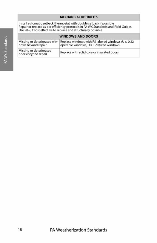
MECHANICAL RETROFITS
Install automatic setback thermostat with double setback if possibleRepair or replace as per efficiency protocols in PA WX Standards and Field GuidesUse 90+, if cost effective to replace and structurally possible
WINDOWS AND DOORS
Missing or deteriorated win-dows beyond repair
Replace windows with R5 labeled windows (U ≤ 0.22 operable windows, U≤ 0.20 fixed windows)
Missing or deteriorated doors beyond repair Replace with solid core or insulated doors
PA W
x St
and
ard
s
Weatherization Field Guide for Pennsylvania 19
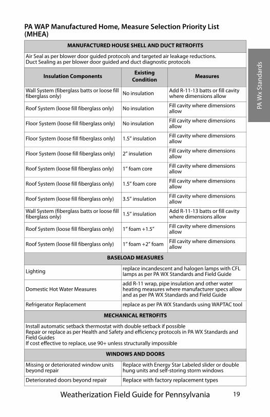
PA WAP Manufactured Home, Measure Selection Priority List (MHEA)
MANUFACTURED HOUSE SHELL AND DUCT RETROFITS
Air Seal as per blower door guided protocols and targeted air leakage reductions.Duct Sealing as per blower door guided and duct diagnostic protocols
Insulation ComponentsExisting
ConditionMeasures
Wall System (fiberglass batts or loose fill fiberglass only) No insulation Add R-11-13 batts or fill cavity
where dimensions allow
Roof System (loose fill fiberglass only) No insulation Fill cavity where dimensions allow
Floor System (loose fill fiberglass only) No insulation Fill cavity where dimensions allow
Floor System (loose fill fiberglass only) 1.5” insulation Fill cavity where dimensions allow
Floor System (loose fill fiberglass only) 2” insulation Fill cavity where dimensions allow
Roof System (loose fill fiberglass only) 1” foam core Fill cavity where dimensions allow
Roof System (loose fill fiberglass only) 1.5” foam core Fill cavity where dimensions allow
Roof System (loose fill fiberglass only) 3.5” insulation Fill cavity where dimensions allow
Wall System (fiberglass batts or loose fill fiberglass only) 1.5” insulation Add R-11-13 batts or fill cavity
where dimensions allow
Roof System (loose fill fiberglass only) 1” foam +1.5” Fill cavity where dimensions allow
Roof System (loose fill fiberglass only) 1” foam +2” foam Fill cavity where dimensions allow
BASELOAD MEASURES
Lighting replace incandescent and halogen lamps with CFL lamps as per PA WX Standards and Field Guide
Domestic Hot Water Measuresadd R-11 wrap, pipe insulation and other water heating measures where manufacturer specs allow and as per PA WX Standards and Field Guide
Refrigerator Replacement replace as per PA WX Standards using WAPTAC tool
MECHANICAL RETROFITS
Install automatic setback thermostat with double setback if possibleRepair or replace as per Health and Safety and efficiency protocols in PA WX Standards and Field GuidesIf cost effective to replace, use 90+ unless structurally impossible
WINDOWS AND DOORS
Missing or deteriorated window units beyond repair
Replace with Energy Star Labeled slider or double hung units and self-storing storm windows
Deteriorated doors beyond repair Replace with factory replacement types
PA W
x St
and
ard
s
PA Weatherization Standards20
SINGLE FAMILY HOME STANDARDS
Agencies should develop the ability through their own employ-ees or through competent contractors to perform air-sealing and insulating procedures outlined in the Field Guide. Prioritize measures according to the “PA WAP Single Family Homes Mea-sure Selection Priority List”. For additional guidance see “Air-Sealing and Insulating” on page 161. Moisture issues must be addressed and resolved before air sealing and insulating.
Conditioned Versus Unconditioned Basements
Determining which weatherization measures to apply in foun-dation spaces depends on whether it is conditioned or uncondi-tioned. Some general guidelines to assist the auditor are as follows:
Conditioned Basement
• Relatively tight or unvented foundation.
• Living space.
• Intentional or unintentional heat delivered to the space.
If you determine that a foundation space is conditioned, air-seal exposed foundation walls or framing, and insulate the band joist. See “Rim insulation and air-sealing” on page 194.
Unconditioned Basement or Crawl Space
• Leaky, vented or severely degraded foundation.
• Not a living space.
• No heat delivered.
If unconditioned, air-seal and insulate the floor cavity between the basement and first floor. In both cases, seal all air pathways between the basement or crawl space and the house. See “Floor insulation” on page 195.
PA W
x St
and
ard
s
Weatherization Field Guide for Pennsylvania 21
Closed Cavity Dense Pack Insulation
Insulate above-grade exterior wall cavities in frame dwellings with dense-packed blown-in insulation where no insulation exists. Use the fill-tube method to ensure complete coverage and acceptable density. Wall insulation is an important and effective retrofit and weatherization agency crews and contractors should obtain what-ever tools, equipment, and training they need to perform this ret-rofit confidently.
Fill other types of closed cavities with dense-packed insulation in areas such as floored attics, cantilevered ceilings, tuck under garage ceilings, manufactured house floors, and manufactured house roof cavities. Use fiberglass instead of cellulose anywhere moisture may be a problem. Choose fiberglass for manufactured houses because it puts less pressure on cavities during installation. Cellulose’s acidic fire retardant may corrode manufactured house metal roofing and siding. See “Air-Sealing and Insulating” on page 161. See “Manufactured Housing Specifications” on page 227.
Window and Door Replacement
Window and door replacements do not have an acceptable SIR on single family homes or manufactured houses. Window and door replacement shall not be performed instead of cost-effective weatherization measures on the priority list. Replacing broken glass or other repairs are acceptable treatments. Window replace-ment or door replacement is not an air sealing measure.
Window and door replacements should only be considered under the following circumstances.
• Higher priority weatherization measures will all be com-pleted within the home’s weatherization budget.
• The existing window or door creates a hazard to the health, safety, and/or building durability.
PA W
x St
and
ard
s
PA Weatherization Standards22
• Existing window or door is damaged or weathered beyond repair, and a replacement option would be less expensive than the repair.
MANUFACTURED HOUSE STANDARDS
Agencies should develop the ability through their own employ-ees or through competent contractors to perform air-sealing and insulating procedures outlined in this field guide. Prioritize measures according to the “PA WAP Manufactured Home, Mea-sure Selection Priority List (MHEA)” on page 19.
In addition to following the priority list and guidance in the chapter on Manufactured House Standards, the following stan-dards also apply to manufactured houses.
• Install a ground vapor barrier in all cases except where there are severe obstructions or evidence of water ponding underneath the home.
• Install blown-in fiberglass insulation only in belly, wall and ceiling cavities.
• Verify the serviceability of existing ventilation fans or install new ventilation fans where none exist.
• Install only heating appliances, windows and doors that are designed for manufactured houses.
• If replacing windows purchase units with self storing storm windows.
• Coat roof seams and edges if the roof has been accessed for activities such as insulation or replacement of a chimney cap.
• Verify that clothes dryers are vented to the outside of the crawl space.
For additional guidance See “Manufactured Housing Specifica-tions” on page 227.
PA W
x St
and
ard
s
Weatherization Field Guide for Pennsylvania 23
Building Repairs
Home repairs to siding or roofing, painting, structural compo-nents for the purpose of protecting weatherization measures are allowable expenditures. Repair items include but are not necessar-ily limited to the following items.
• Minor roof repair including roof leaks, flashings, gutters and downspouts.
• Repair plumbing leaks.
• Minor structural repairs such as reinforcing dropped ceilings, floor repair, etc.
HEATING-SYSTEM STANDARDS
The goal of heating-system service, provided during weatheriza-tion, is to make systems safer, more efficient, and to preserve them. To accomplish these goals, weatherization agencies or their sub contractors perform some of these services.
• Cleaning and tuning of gas and oil burners.
• Replacement of conventional oil burners with flame-reten-tion-head burners on boilers only. Unit should have addi-tional expected life of 15 years.
• Replacement of unsafe or inefficient heating units with high-efficiency units.
• Improving distribution systems on forced air, hot water and steam systems.
See “Heating System Specifications” on page 87.
Heating Systems Testing
Appliances used to heat homes and heat water for domestic use should operate safely and efficiently. All vented space-heating and water-heating appliances must be visually inspected and tested, using a combustion analyzer. Correct any safety problems before
PA W
x St
and
ard
s
PA Weatherization Standards24
weatherization is completed. Document any preexisting safety issues for both standard weatherization and Crisis programs.
Inspect all operating units for obvious venting defects. Gas sup-ply lines should be tested for fuel leaks, and clearances to com-bustibles checked. Report any deficiencies concerning these units to the building occupant and owner in writing. With the exception of assuring chimney safety, no combustion analysis should be performed on coal- or wood-burning appliances. See “Combustion safety and efficiency testing” on page 88.
Chimney Safety
Assessing chimney safety and making chimney repairs are some of the most important measures to insure home health and safety. Categories of venting improvements include the follow-ing items.
• Clearing obstructions from chimneys and flues.
• Replacement of corroded, poorly designed, or illegal, vent connectors.
• Fan assisted sidewall venting.
• Relining chimneys.
• Replacement of non-vented space heaters with vented units.
See “Venting combustion gases” on page 109.
Worst Case Chimney Safety Testing
Depressurization, blocked chimneys, and installation flaws are leading causes of back drafting and spillage. All homes must have a worst-case depressurization and draft test after all weath-erization work has been performed. Its purpose is to insure that all vented combustion appliances have adequate chimney draft. The test can isolate sources of depressurization which may include exhaust fans, return ducts, the furnace blower, and chimneys themselves. The test may be performed by either the
PA W
x St
and
ard
s
Weatherization Field Guide for Pennsylvania 25
field technician or by the final inspector upon completion of weatherization and must be documented. See “CAZ Combustion Safety Test” on page 103. and See “Improving inadequate draft” on page 108.
Duct Induced Pressures
Other types of testing on forced air systems can help diagnose comfort and infiltration related problems caused by unbalanced forced air systems. See “Duct-induced pressures” on page 223.
Unvented Space Heaters
Unvented space heaters are particularly dangerous heating devices, known to cause high levels of moisture and carbon mon-oxide. Unvented space heaters may not be used as a primary heat source. They may only be used as a secondary or emergency heat source. Refer to DCED Directive.
Vented space heaters may be installed to replace unvented space heaters when used as a primary heat source. In this case, the unvented space heater must be removed from the premises and destroyed. See “Venting combustion gases” on page 109.
Combustion Air
Assure that all fossil-fuel-fired heating systems have an adequate source of combustion air. See “Combustion air” on page 126.
Replacement Heating Units
Don’t assume that older furnaces and boilers are unsafe or ineffi-cient until testing them. During testing, make appropriate efforts to repair and adjust the existing furnace or boiler, before deciding to replace it. Most replacement parts are commonly available.
Heating appliances are often replaced when the cost of repairs and retrofits exceeds one half of estimated replacement costs. Estimate the repair and retrofit costs and compare them to replacement cost before deciding between retrofit and replacement. Replace the heating unit that meets one or more of these conditions.
PA W
x St
and
ard
s
PA Weatherization Standards26
• A furnace that has a cracked heat exchanger.
• A boiler that has a leaking heat exchanger.
• The furnace cabinet and a majority of other critical compo-nents are corroded or deemed beyond repair.
• A standard tune-up will not bring the heating unit in line with minimum health, safety or efficiency standards set forth in “Combustion Standards for Gas Furnaces” on page 91 and “Combustion Standards for Oil-Burning Appliances” on page 96.
Document the reasons for replacement.
When a heating unit is replaced, the weatherization agency is responsible for assuring that an accurate heat loss calculation is performed on the house for the purpose matching the heating units output with the heat-loss rate of the house. This calcula-tion must use the “Manual J” protocol and should take into account any weatherization work that is planned for the build-ing. Sizing considerations should be 100% of the calculated heating load for the structure. Document this calculation in the client file.
BASELOAD ENERGY STANDARDS
The energy used by electric or gas appliances in a home that is not used for space conditioning is referred to as baseload energy use. The following measures are approved as qualifying baseload measures for PAWAP.
Refrigerator Replacement
Evaluate the home’s primary refrigerator. The primary refrigera-tor may be replaced if an SIR of 1 or greater is obtained using the WAPTAC Refrigerator Replacement Tool.
See “Refrigerator Replacement” on page 50.
PA W
x St
and
ard
s
Weatherization Field Guide for Pennsylvania 27
Refrigerator Maintenance
• Test and adjust temperature (optimal freezer 0º - 5º, optimal fresh food 36º-40º).
• Energy Education.
Lighting
• CFL replacement of incandescent bulbs used 2 hours per day or more including outside and halogen torchieres.
Clothes Dryer Improvements
• Replacement of flex duct with smooth metal pipe.
• Energy Education.
Water Heating
• Replace water heaters that are unsafe or leaking.
• Standard hot water conservation measures.
ADMINISTRATIVE ISSUES
All baseload measure justifications must be documented in the client file on DCED approved forms.
Incorporating Baseload Measures into Job Costs
The intent of incorporating baseload measures into the program is to enhance the opportunity for energy savings for particular dwelling units.
The mission of the program is to identify the combination of mea-sures including shell, mechanical and baseload measures that will provide the greatest savings for a particular unit. Baseload mea-sures are to be incorporated into average Weatherization job costs. The benefit of adding baseload measures to Weatherization will be especially apparent in homes that have high baseload consump-tion and moderate heating consumption. Auditors will have a
PA W
x St
and
ard
s
PA Weatherization Standards28
wider array of choices to target Weatherization dollars for great-est impact. This is intended not only to provide for greater over-all energy savings but also to provide energy savings opportunities for a larger number of low-income households.
When screening clients for weatherization eligibility it is sug-gested that agencies determine if clients have already partici-pated in utility baseload programs. If they have not and are eligible, agencies may elect to coordinate baseload referrals and/or service delivery with client’s electric utility. In this way, basel-oad dollars from State funded weatherization can be targeted to non-eligible electric customers with rural electric cooperatives and municipal providers.
Access to clients’ electric and fuel bills will be helpful for the auditor to determine the greatest potential for savings in the home. If this information is not gathered for client’s file, the auditor may request that the client has energy bill or records available to evaluate baseload use during the audit.
See “Assessing baseload energy-saving opportunities” on page 49.
HEALTH AND SAFETY STANDARDS
The Department of Energy’s Weatherization Assistance Pro-gram allows expenditure of its funds to address and mitigate health and safety hazards associated with weatherization.
Crew or Contractor Health and Safety
Every weatherization agency and contractor must have a written health and safety plan for workers, according to the Occupa-tional Safety and Health Administration (OSHA). Every employee should be trained on safety and should understand the most statistically dangerous hazards present at their work-place. Employees should know how to avoid these dangerous hazards. Agencies and contractors must conduct regular safety meetings and encourage workers to report unsafe conditions.
PA W
x St
and
ard
s
Weatherization Field Guide for Pennsylvania 29
Agencies or contractors, who currently lack a written health and safety plan, are encouraged to use the information in “Worker health and safety” on page 77 as their health and safety plan. Using this information requires a commitment to worker health and safety, extending from management down to each and every employee.
Client Health and Safety
Weatherization must be provided in a manner that minimizes risks to clients. The Weatherization Assistance Program can’t provide solutions for all health and safety issues. Awareness of potential hazards is essential to providing quality weatherization services. Therefore, each dwelling must be individually assessed to deter-mine the existence of potential hazards to workers and clients.
The Agency should make every attempt to solve health and safety problems using a $300 repair allowance and the $300 health and safety allowance. If $600 is inadequate, DCED may, at their discre-tion, grant permission to exceed the repair and health and safety allowances. The exception to this guideline are heating appliance replacements due to cracked heat exchangers or unserviceable heating units. Housing funds from U.S. Department of Housing and Urban Development, U.S. Department of Health and Human Services, U.S. Department of Agriculture, and local organizations should be used to solve more expensive health and safety prob-lems.
Local agencies and their representatives are to take reasonable precautions against performing work on dwellings, where that work will expose clients to health and safety risks.
In cases where work activities would constitute a health and safety hazard, action is required to limit or avoid particular measure(s), which may exacerbate a health or safety problem. See “Client health and safety” on page 63.
PA W
x St
and
ard
s
PA Weatherization Standards30
Moisture Problems
Air-sealing work may not be performed on a home that exhibits evidence of extreme moisture problems. Moisture problems must be resolved before beginning air sealing activities. Evi-dence of moisture problems includes, but is not limited to, the following:
• Evidence of significant bulk moisture entering the building.
• Significant amount of water in basements or crawl spaces.
• Rotted or moldy roof sheathing.
• Significant mold present on interior building surfaces.
• Significant condensation on interior building surfaces such as windows.
See “Symptoms of moisture problems” on page 70.
Moisture abatement may include but is not limited to the fol-lowing.
• Installation of a ground moisture barrier.
• Control ground-source moisture problems by improving grading, drainage.
• Installation or repair of a gutter or downspout.
• Installation or repair of the exhaust ventilation.
• Installation or replacement of a sump pump.
Clients should also be encouraged to take an active role in resolving moisture problems on their own before weatherization work may begin by performing activities such as unclogging a plugged drain or removal of moisture absorbing or unsanitary materials. See “Solutions to moisture problems” on page 74.
Mold
Risk assessment, abatement, hazard control or removal of mold is not an allowable activity under the DOE Weatherization Pro-
PA W
x St
and
ard
s
Weatherization Field Guide for Pennsylvania 31
gram. However, work that is needed to prevent mold is allowable. Measures described under “Moisture Problems”, “Building Air-flow Standard” and “Shell Measures” may prevent or arrest the development of mold. Costs associated with this activity will be charged as health and safety costs and will not be included in the average cost per home limitation.
Severe Indoor Air Quality Problems
Severe indoor air quality problems, observed at the time of the audit, may disqualify a home from air sealing treatments until the problems are solved. These problems include but are not limited to the following conditions.
• Unsanitary conditions that would put workers at risk or increase risk to the occupants.
• Complaints on the part of occupants that they feel ill when in the home.
• Production of high levels of CO in combustion appliances, including cook stoves.
See “Respiratory health” on page 81. and See “Gas range and oven safety” on page 66.
Building Airflow Standard (BAS)
Dwelling units must not be tightened below a level where health, safety, building integrity and indoor air quality may be compro-mised. A combination of blower door testing and other protocols must be used to provide sufficient assurances consistent with this goal, including issues related to the following.
• Unvented space heater present.
• Indoor air quality and moisture survey.
• BAS
• Chimney safety performance testing.
• Client education.
PA W
x St
and
ard
s
PA Weatherization Standards32
The auditor and technicians are expected to adjust the BAS to account for moisture problems and other indoor air quality problems or to avoid air-sealing altogether if solving the prob-lems are beyond the scope of the weatherization program. See “Building Airflow Standard (BAS)” on page 211.
Inadvertent Over-Tightening
There are instances where technicians can quite easily tighten a house below the BAS. This is often the case with small volume structures, such as manufactured houses. If the home’s BAS is below the calculated limit, greater care must be directed towards client education, and to providing assurances that greater mois-ture levels or other indoor air quality problems will not develop. Costs associated with installing mechanical spot source ventila-tion or repairing existing mechanical ventilation are allowable under the health and safety provisions.
Lead-Based Paint Hazards
Risk assessment, abatement, hazard control or stabilization of lead-based paint is not an allowable activity under the DOE Weatherization Program. However, work that is needed to pre-vent generation of dust and residues while performing approved weatherization measures that disturb surfaces that may contain lead based paint is allowable. Costs associated with this activity will be charged as health and safety costs and will not be included in the average cost per home limitation. DOE Lead-Safe Weatherization (LSW) is necessary to prevent the possible exposure and effects of lead to both crew personnel and occu-pants of the dwelling. Lead safe weatherization as identified are to be performed on dwellings. Refer to the current lead paint protocol established by DOE and EPA.
A copy of the current EPA lead pamphlet will be provided to occupants residing in pre 1978 dwellings, as well as written cer-tification of receipt prior to the start of weatherization work.
PA W
x St
and
ard
s
Weatherization Field Guide for Pennsylvania 33
All weatherization employees and sub-contractors, whose work duties may result in the disturbance of lead based paint in the course of weatherization, must receive training/certification in lead safe weatherization approved by EPA and DOE. See “Lead-safe weatherization” on page 76.
OTHER HEALTH AND SAFETY ISSUES
Building structural integrity must be assessed at the time of the audit. Certain repairs to the building structure are allowable if they can be completed as a health and safety measure or under the minor repair category, and are necessary for the proper installa-tion of an approved weatherization measure. If adequate repair cannot be accomplished the sub-grantee must take the following steps.
Refer the client to other available housing programs to make the necessary repairs.
Provide the client reasonable opportunity to make the appropriate repairs to the building.
In some instances, it may be necessary to omit a particular weatherization measure due to the condition of a building component. If the building structure is in such disrepair as to make the majority of needed measures ineffective, weath-erization may be denied to the client.
Electrical wiring may be susceptible to safety problems resulting from weatherization activities such as insulation retrofits. Agen-cies are directed to follow specifications outlined in “Electrical safety” on page 170 to avoid electrical and fire hazards.
Replace Halogen floor lamps with fluorescent floor lamps. Halo-gen lamps are now considered to be an extreme fire hazard. See “Halogen Lamps” on page 56.
Asbestos, which is friable, is not permitted to be removed, cov-ered, encapsulated, or disturbed during weatherization activities. Dwelling occupants will be given written notice of such discovery, along with the address and telephone number of the regional EPA
PA W
x St
and
ard
s
PA Weatherization Standards34
asbestos coordinator. If requested, a reasonable period of time for asbestos removal and clean-up will be given prior to weath-erization.
Other code issues are the responsibility of the sub-grantee to insure that weatherization related work conforms with applica-ble codes in jurisdictions where the work is being performed.
DEFERRAL OF WEATHERIZATION SERVICES
The decision to defer work in a dwelling or, in extreme cases, provide no weatherization services, is difficult but necessary in some cases. This does not mean that services will never be avail-able, but that work must be postponed until the problems can be resolved. Agencies are expected to pursue all reasonable options on behalf of the client. Know the options for housing repair funds in your region, and help weatherization clients apply for and obtain funding to make repairs that, if left undone, would force you to deny weatherization services.
A deferral is contained in a letter to the client explaining the severe circumstances, leading to the decision to defer weather-ization services. The deferral letter must be included in the cli-ent file. Reasons for deferral of services include, but are not limited to, the following items.
• The household income may exceed federal poverty guide-lines.
• The client or a household member acts in an uncoopera-tive, threatening or abusive manner.
• Criminal behavior is observed in the household.
• Client creates a health, safety, or sanitary risk and refuses to correct the problem.
• Client refuses recommended Priority List health and safety measures.
PA W
x St
and
ard
s
Weatherization Field Guide for Pennsylvania 35
• Client has known health problems which would preclude insulation or other weatherization materials from being installed.
• Pet containment.
• The building structure or its mechanical systems are in such a state of disrepair that the conditions cannot be resolved cost-effectively.
• The house or site-built/manufactured housing has been con-demned for electrical, plumbing, or any other issues, with the exception of heating appliances.
• The house or site-built/manufactured housing has sewage or other sanitary problems that would further endanger the cli-ent and installers if weatherization work was performed.
• Moisture problems are so severe that they cannot be resolved under existing health and safety measures and with minor repairs.
• Dangerous conditions exist due to high carbon monoxide levels in combustion appliances that cannot be resolved under existing health and safety measures and with minor repairs.
• The extent of and condition of lead based paint in the house would create further health and safety hazards.
FINAL INSPECTION
A sub-grantee representative will inspect the completed work and obtain a “completion verification” from the client. This verifica-tion will become part of the permanent client file record. Also included in the final inspection report is an assurance that installed measures were explained to the client and that client edu-cation was provided. The inspector must verify that the measures, listed on the job report or invoice, were installed on the home and that they were properly installed in accordance with these stan-dards described in this field guide.
PA W
x St
and
ard
s
PA Weatherization Standards36

Aud
it, E
duc
atio
n,
Base
load
and
Hot
Wat
er
Weatherization Field Guide for Pennsylvania 37
CHAPTER TITLE: AUDITING, EDUCATION, BASELOAD AND HOT WATER SAVINGS
Energy-auditing has a logic and a sequence of steps determined by the auditor, the policies of the weatherization agency, and the residence being audited. Before deciding which weatherization measures to install in a particular home you should understand how the home uses energy.
Decisions about which measures to install are determined by visual inspection, auditing experience, practical considerations, and the results of computerized energy-auditing programs like NEAT and MHEA.
Those measures which reduce baseload consumption according to Pennsylvania’s baseload standards are cost-effective energy savers for most homes and don’t require much analysis. These measures may even be installed during the weatherization audit by the auditor. They are covered at the end of this chapter.
The chapters that follow this one are arranged to reflect the auditing process, with measures and testing that are first in sequence and importance being addressed first within each chapter.
Also covered in this chapter is client education. A client can reduce energy consumption, using the suggestions listed here, without any weatherization work. If the auditor is persuasive enough about the benefits of energy-saving habits, weatheriza-tion efforts will be measurably more successful than if client education is neglected.
See “Baseload Energy Standards” on page 26.
Aud
it, E
duc
atio
n,
Base
load
and
Hot
Wat
er
38
TITLE.1 UNDERSTANDING ENERGY USAGE
Energy usage can be divided into two categories: baseload and seasonal energy use. Baseload includes water heating, lighting, refrigerator, and the use of other year-round appliances. Sea-sonal energy use includes heating and cooling.
The challenge of energy auditing is to determine where the loss is and to allocate weatherization resources according to the potential a particular home has for energy loss reduction.
Seasonal energy use is much more variable and difficult to reduce than baseload energy use. In particular, reducing heating costs has become a complex endeavor because of diagnostic procedures and linkages to health and safety.
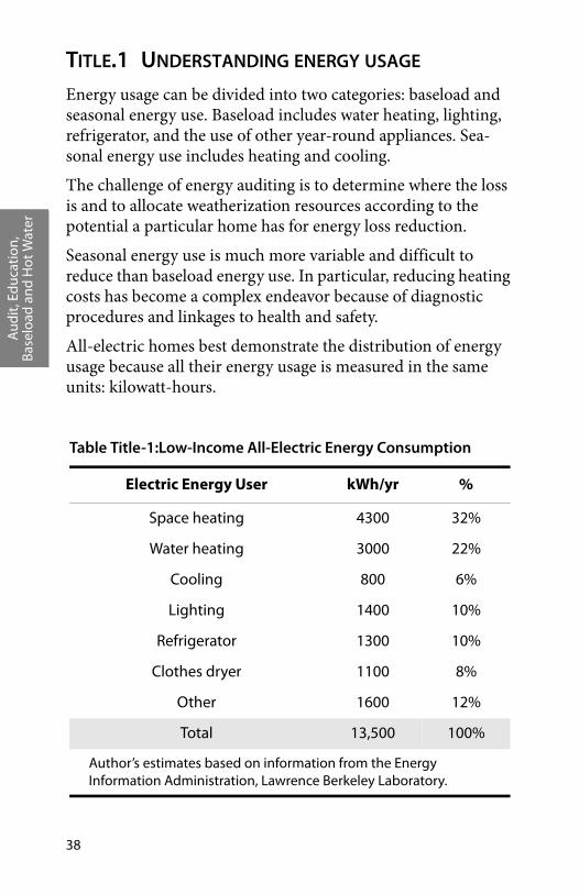
All-electric homes best demonstrate the distribution of energy usage because all their energy usage is measured in the same units: kilowatt-hours.
Table Title-1:Low-Income All-Electric Energy Consumption
Electric Energy User kWh/yr %
Space heating 4300 32%
Water heating 3000 22%
Cooling 800 6%
Lighting 1400 10%
Refrigerator 1300 10%
Clothes dryer 1100 8%
Other 1600 12%
Total 13,500 100%
Author’s estimates based on information from the Energy Information Administration, Lawrence Berkeley Laboratory.

Aud
it, E
duc
atio
n,
Base
load
and
Hot
Wat
er
Weatherization Field Guide for Pennsylvania 39
Each of the energy uses in the pie chart deserves consideration on every home. Insulation levels can be determined easily from observation, but air leakage and heating performance require extensive testing. Water heating is of special interest because of its year-round expense of $15 to $35 per month. Avoid getting too focused on a single loss category.
Lighting: 1400Cloth
es Dry
er: 1100
Space
Hea
ting:
430
0W
ater
Hea
tin
g: 3
00022%
32%
10%
8%
12%
Other: 1600
Cooling: 800
Refrigerator: 1300
10%
Other: 1600
12%
6%
Improvable baseload and seasonal energy uses: In northern climates heating is the biggest energy user, other energy uses can’t be neglected in a comprehensive weatherization program, which seeks maximum energy savings.
Space Heating Ener gy
R-V alues Air Leakage
Equipment Efficienc y
Water Heating Energy
Tank R-Value Hot-Water Usage
Water Temperature
Heating energy waste: Heating energy loss fits into three categories. The challenge to reducing heating costs is finding the largest pockets of energy waste and spending resources on the major problems.
Water-heating energy loss: The challenge to reducing water-heating costs is ensuring that all three loss categories have been improved.
Aud
it, E
duc
atio
n,
Base
load
and
Hot
Wat
er
40
TITLE.2 WEATHERIZATION WORK FLOW
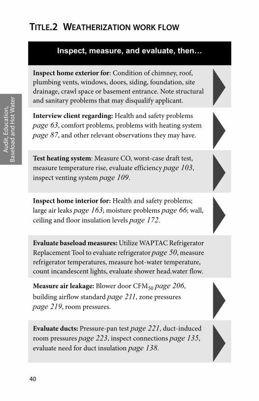
Inspect, measure, and evaluate, then…
Inspect home exterior for: Condition of chimney, roof, plumbing vents, windows, doors, siding, foundation, site drainage, crawl space or basement entrance. Note structural and sanitary problems that may disqualify applicant.
Interview client regarding: Health and safety problems page 63, comfort problems, problems with heating system page 87, and other relevant observations they may have.
Test heating system: Measure CO, worst-case draft test, measure temperature rise, evaluate efficiency page 103, inspect venting system page 109.
Inspect home interior for: Health and safety problems; large air leaks page 163; moisture problems page 66; wall, ceiling and floor insulation levels page 172.
Evaluate baseload measures: Utilize WAPTAC Refrigerator Replacement Tool to evaluate refrigerator page 50, measure refrigerator temperatures, measure hot-water temperature, count incandescent lights, evaluate shower head.water flow.
Measure air leakage: Blower door CFM50 page 206, building airflow standard page 211, zone pressures page 219, room pressures.
Evaluate ducts: Pressure-pan test page 221, duct-induced room pressures page 223, inspect connections page 135, evaluate need for duct insulation page 138.
Aud
it, E
duc
atio
n,
Base
load
and
Hot
Wat
er
Weatherization Field Guide for Pennsylvania 41
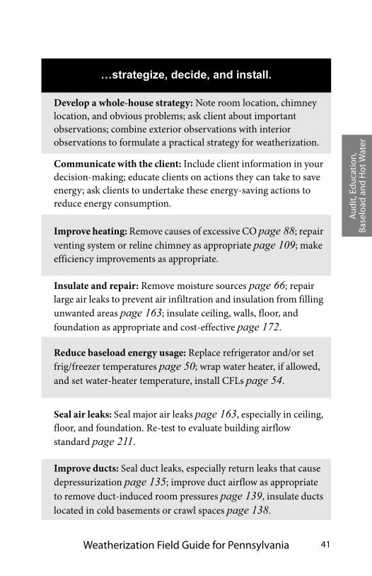
…strategize, decide, and install.
Develop a whole-house strategy: Note room location, chimney location, and obvious problems; ask client about important observations; combine exterior observations with interior observations to formulate a practical strategy for weatherization.
Communicate with the client: Include client information in your decision-making; educate clients on actions they can take to save energy; ask clients to undertake these energy-saving actions to reduce energy consumption.
Improve heating: Remove causes of excessive CO page 88; repair venting system or reline chimney as appropriate page 109; make efficiency improvements as appropriate.
Insulate and repair: Remove moisture sources page 66; repair large air leaks to prevent air infiltration and insulation from filling unwanted areas page 163; insulate ceiling, walls, floor, and foundation as appropriate and cost-effective page 172.
Reduce baseload energy usage: Replace refrigerator and/or set frig/freezer temperatures page 50; wrap water heater, if allowed, and set water-heater temperature, install CFLs page 54.
Seal air leaks: Seal major air leaks page 163, especially in ceiling, floor, and foundation. Re-test to evaluate building airflow standard page 211.
Improve ducts: Seal duct leaks, especially return leaks that cause depressurization page 135; improve duct airflow as appropriate to remove duct-induced room pressures page 139, insulate ducts located in cold basements or crawl spaces page 138.
Aud
it, E
duc
atio
n,
Base
load
and
Hot
Wat
er
42
TITLE.3 CLIENT EDUCATION
Client education is a potent weatherization measure. A well-designed education program engages families in household energy management and assures the success of weatherization measures such as compact fluorescent lamp installation, setback thermostat installation, and furnace filter maintenance. Clients can enhance our weatherization efforts by developing good hab-its for using energy wisely. The following recommendations are designed to save energy without overwhelming the client.
Title.3.1 Education hand-in-hand with other WAP treatments
The Commonwealth of Pennsylvania introduced education as a part of the Weatherization Assistance Program during the 1988 – 1989 program year. Since that time all Grantees have been directed to develop and implement an education component as an integral part of their individual weatherization programs. This directive was based largely on the 1987 evaluation that showed a 7% energy savings when education was coupled with standard weatherization treatments. Since then, other evalua-tions in Philadelphia and around the country have verified that energy education can be an extremely cost effective treatment as part of traditional Weatherization Assistance Program. This is totally consistent with current WAP+ design where both the house and the customer are treated holistically. To be most effective, education should be either delivered along with house treatments or come directly after the treatments have been per-formed.
Like all other components of a weatherization program, educa-tion is only effective when properly designed and implemented. The specifics of implementing an education program will cer-tainly vary from agency to agency because of contracts, custom-ers, housing stock, staff and contractors.
Aud
it, E
duc
atio
n,
Base
load
and
Hot
Wat
er
Weatherization Field Guide for Pennsylvania 43
The Audit or Estimate “calls out” a set of treatments needed to solve particular problems found in a house. When effective, these treatments will lower utility usage, save the customer money and create a safer, more comfortable environment, how-ever, these treatments may not address the full range of prob-lems reported by the customer and certainly not address customer habits. When performed effectively, customer educa-tion can fill this gap and help the customer to maximize all the potential benefits of the Weatherization Assistance Program. The following guidelines have been developed through the experience of WAP Grantees across the country over the last ten years.
Simple guidelines to help assure education program success
Design your program to focus on customer needs, because effective education is need-based. Reciting a checklist of energy saving options is usually worthless. People don’t care about item num-ber nine. People care first that you care and then if you can offer real solutions to real problems they have spelled out. The con-tent of your education program should be as broad as your cus-tomer’s needs but focused on the highest utility usage. Most non-energy issues can be addressed by referrals to other social service programs inside or outside of your agency.
Get and keep the customer’s attention and focus by making the session interactive with self-help materials and visuals, especially by using house problems as part of a “walk-through”. Keep the session as simple as possible by focusing on opportunities that will yield the biggest savings or produce the greatest comfort. Dividing the education into discrete tasks helps to keep the cus-tomer from being overwhelmed.
Guarantee good communication: through active conversation (asking questions and really listening to the answers) and hands-on demonstrations.

Aud
it, E
duc
atio
n,
Base
load
and
Hot
Wat
er
44
Connect tasks: to something physical like hands-on demonstra-tions and, to a lesser degree, paperwork. Educational forms and customer sign-offs can also help assure that education work is consistent across all educators.
What is Effective Communication
You know your communication has been successful when the person(s) you are talking with have heard what you wanted them to hear and you know this, because they have repeated, drawn or demonstrated your information back to you in a clear manner.
Table Title-2:Qualities of an Effective Educator
1. Knowledgeable 2. Clear
3. Patient 4. Demonstrates points
5. Understands per-sonalities
6. Helpful
7. Concerned 8. Active
9. Listens well 10. Helps audience visu-alize information
11. Persistent 12. Presents alternatives
13. Firm 14. Sets expectations
15. Asks for feed-back
16. Identifies audience skill level
17. Positive outlook 18. Knows own limita-tions
19. Non-confronta-tional
20. Willing to meet someone on their level
Aud
it, E
duc
atio
n,
Base
load
and
Hot
Wat
er
Weatherization Field Guide for Pennsylvania 45
Title.3.2 Reducing heating costs
The auditor should suggest the following practices for reducing heating costs.
Set thermostat back 5 to 10 degrees at night or when no one is home.
Check furnace filters monthly during the heating or cool-ing season, and change or clean them as necessary.
Open all registers, and don’t obstruct them with furniture or rugs.
Clean grills when they appear dusty.
Check prime and storm windows regularly during cold weather to make sure they are closed.
Oil-fired heating systems should be serviced annually.
Title.3.3 Hydronic heating systems
Additionally, the auditor should explain the following general practices for homeowners who have a hot water or steam boiler system for home heating.
Hot water systems
Periodically bleed the radiators of any excess air. After bleeding air, read the boiler pressure gauge to confirm that the system pressure is still within the specified limits.
Drain the expansion tank every three years or sooner if the radiators seem to have a lot of air or if the safety relief valve keeps blowing out.
Have the boiler cleaned and tuned annually by qualified personnel.
Steam systems (identified by a sight glass that shows boiler water level)

Aud
it, E
duc
atio
n,
Base
load
and
Hot
Wat
er
46
Drain the float chamber and check the low water cutoff weekly. Open the blow-down value and flush the sediment into a bucket until the water runs clear.
After flushing the float chamber, confirm the proper oper-ation of the automatic make-up water valve by checking the sight glass for proper water level.
Have the steam boiler cleaned and tuned annually by qual-ified personnel.
Title.3.4 Hot-water and laundry savings
The auditor should suggest the following habits for reducing hot-water and laundry energy costs.
If replacing the faucet is necessary, install a model with two separate knobs. Reach for the cold water tap unless you need hot water.
Wash clothes in cold water unless warm or hot water is needed to get dirty clothes clean.
Wash and dry full loads of clothes.
Clean the dryer lint filter after each load.
Use the automatic electronic cycle. Note the dial reading that gets clothes acceptably dry and use that setting consis-tently.
Reach for the cold-water tap: Unless you need hot water, use cold.
Aud
it, E
duc
atio
n,
Base
load
and
Hot
Wat
er
Weatherization Field Guide for Pennsylvania 47
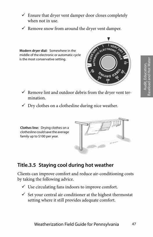
Ensure that dryer vent damper door closes completely when not in use.
Remove snow from around the dryer vent damper.
Remove lint and outdoor debris from the dryer vent ter-mination.
Dry clothes on a clothesline during nice weather.
Title.3.5 Staying cool during hot weather
Clients can improve comfort and reduce air-conditioning costs by taking the following advice.
Use circulating fans indoors to improve comfort.
Set your central air conditioner at the highest thermostat setting where it still provides adequate comfort.
1020
304050
60
TIM
EDDRYING
AU
TOMAT
ICELECTRONIC CYC
LE
VERY DRY
LE
SS
DRY
O F F
OFF
Modern dryer dial: Somewhere in the middle of the electronic or automatic cycle is the most conservative setting.
Clothes line: Drying clothes on a clothesline could save the average family up to $100 per year.
Aud
it, E
duc
atio
n,
Base
load
and
Hot
Wat
er
48
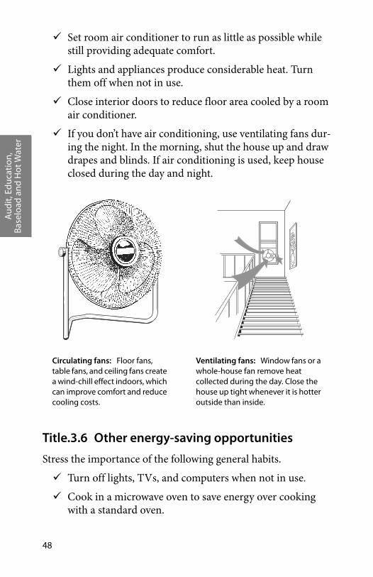
Set room air conditioner to run as little as possible while still providing adequate comfort.
Lights and appliances produce considerable heat. Turn them off when not in use.
Close interior doors to reduce floor area cooled by a room air conditioner.
If you don’t have air conditioning, use ventilating fans dur-ing the night. In the morning, shut the house up and draw drapes and blinds. If air conditioning is used, keep house closed during the day and night.
Title.3.6 Other energy-saving opportunities
Stress the importance of the following general habits.
Turn off lights, TVs, and computers when not in use.
Cook in a microwave oven to save energy over cooking with a standard oven.
Circulating fans: Floor fans, table fans, and ceiling fans create a wind-chill effect indoors, which can improve comfort and reduce cooling costs.
Ventilating fans: Window fans or a whole-house fan remove heat collected during the day. Close the house up tight whenever it is hotter outside than inside.

Aud
it, E
duc
atio
n,
Base
load
and
Hot
Wat
er
Weatherization Field Guide for Pennsylvania 49
TITLE.4 ASSESSING BASELOAD ENERGY-SAVING OPPORTUNITIES
The energy used by electric or gas appliances in a home that is not used for space conditioning is referred to as baseload energy use. This basic energy load includes lighting, refrigeration, water heating, cooking, laundry appliances and electronics. It does not include heating or air conditioning loads, which is referred to as seasonal energy use. Seasonal energy use is addressed through standard weatherization retrofits.
Baseload energy use does vary throughout the year. Lighting and water heaters are used more during the winter months where refrigerators, well pumps, and dehumidifiers are used more during summer months. However, these variations usually account for only about a 10% increase or decrease in baseload use. Some appliances and plug loads are used seasonally, such as holiday lights, pool pumps, and fans. A weatherization auditor needs to be aware that these items impact the evaluation of the total seasonal use.
It is always a best practice to integrate a Baseload Audit with Energy Education. Total electricity and gas use relates directly to potential electricity and gas savings. Customers who use more electricity and gas tend to save more after weatherization and education services, and are therefore, more cost effective to serve. A Baseload Auditor and Energy Educator must be able to look at a customer’s usage patterns and determine if there are opportunities for savings. Baseload energy use is very connected to energy practices in the home. Auditors have a unique oppor-tunity to communicate the operating costs of existing appliances and practices and the savings potential to the client.
The baseload standards that follow define approved conserva-tion measures and methods that will reduce the baseload energy consumption of weatherization clients.
Aud
it, E
duc
atio
n,
Base
load
and
Hot
Wat
er
50
TITLE.5 REFRIGERATOR REPLACEMENT
Refrigerators manufactured before 1990 usually consume over 1000 kilowatt-hours per year. New Energy Star® rated refrigera-tors use less than 550 kilowatt-hours per year, and many use less than 400 kilowatt-hours per year. Replacement should be con-sidered on a case-by-case basis depending on existing refrigera-tor energy consumption.
Title.5.1 Refrigerator Testing Criteria
The following method may be used to determine eligibility for replacement.
• Use the WAPTAC Refrigerator Analysis Tool, found at www.waptac.org/Refrigerator-Guide/Analysis-Tool.aspx. If the database is used, find the model in the Analysis Tool database and proceed to find the SIR. If the Analysis Tool database does not contain the model, use the Kouba-Cavallo database found at www.kouba-cavallo.com. Enter the annual KWH usage from the database and proceed to find the SIR. If the SIR is 1 or greater, the refrigerator can be replaced.
Title.5.2 Refrigerator Testing Methodology
Refer to DCED Directive which contains guidance on the implementation of the Refrigerator Replacement Program.
It is allowable to meter secondary refrigerators or freezers as an educational tool for the client to discontinue or limit use of sec-ondary units. The client should be encouraged to give up two or more units for one larger unit.
Title.5.3 Waivers, Warranties, Release of Accountability
If eligible for replacement, a client must sign a release statement. They must agree to trade the old unit for the new unit. The
Aud
it, E
duc
atio
n,
Base
load
and
Hot
Wat
er
Weatherization Field Guide for Pennsylvania 51
agreement should include a hold-harmless clause for damages during delivery.
Warranty issues are between the client and the vendor. Leave the vendor information and warranty card with the client to com-plete and send in.
Measure actual clearance of exterior doors, interior doors and appliance cabinets and compare to appliance specifications to select a model that is deliverable and will fit into client’s avail-able space. Recommend delivery with refrigerator door and base grill removed if needed.
If the client is a renter, obtain a signature from the landlord ver-ifying ownership of the existing refrigerator(s) and acknowledg-ing that any appliance replacement will be the property of the same owner. This may be best obtained during eligibility screen-ing for weatherization.
Replacement units must meet the following size and feature replacement criteria.
• Replacement model is a comparable size.
• Client has been shown a picture of the new unit.
• Compare the size of the existing unit’s fresh food compart-ment and freezer with those of the new unit so the client is not surprised if there is a difference.
• If a client is willing to trade in more than one unit, they are eligible for the next size larger replacement model.
Upright, chest and freezer only appliances are not eligible for replacement. If, however, a client owns an inefficient 15 cubic foot refrigerator/freezer and a stand-alone freezer only, the agency may replace both units with a new 18-21 cubic foot refrigerator-freezer unit if the energy savings compared to both existing units justify the measure.
Replacement refrigerators should have the following features.
• White in color.
Aud
it, E
duc
atio
n,
Base
load
and
Hot
Wat
er
52
• Freezer on top.
• Auto defrost.
• Standard shelving.
• No ice maker (except when present on old unit).
• No front mounted water or ice dispenser.
• Reversible doors.
• Easy-roll wheels.
• Up-front controls.
• No side by side refrigerator freezer combination units.
New units will not work if the ambient room temperature is below 60 degrees. Be sure to place the new unit in the house and not the garage or basement if those areas don’t stay over 60 degrees year round.
Title.5.4 Disposal of Refrigerators
The refrigerator vendor must haul away and decommission every old appliance that is replaced. The refrigerator vendor must perform refrigeration recovery according to EPA guide-lines. Certifiable proof of decommissioning must be provided by the vendor with billing and included in the Weatherization client file.
Title.5.5 Refrigerator Maintenance Energy Education Topics
Coil Cleaning
If a refrigerator is not eligible for replacement, show client how to brush and clean condenser coils. Turn unit off to prevent exhaust fan from running while cleaning as the brush could catch in the fan blades.
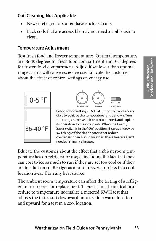
Aud
it, E
duc
atio
n,
Base
load
and
Hot
Wat
er
Weatherization Field Guide for Pennsylvania 53
Coil Cleaning Not Applicable
• Newer refrigerators often have enclosed coils.
• Back coils that are accessible may not need a coil brush to clean.
Temperature Adjustment
Test fresh food and freezer temperatures. Optimal temperatures are 36-40 degrees for fresh food compartment and 0–5 degrees for frozen food compartment. Adjust if set lower than optimal range as this will cause excessive use. Educate the customer about the effect of control settings on energy use.
Educate the customer about the effect that ambient room tem-perature has on refrigerator usage, including the fact that they can cost twice as much to run if they are set too cool or if they are in a hot room. Refrigerators and freezers run less in a cool location away from any heat source.
The ambient room temperature can affect the testing of a refrig-erator or freezer for replacement. There is a mathematical pro-cedure to temperature normalize a metered KWH test that adjusts the test result downward for a test in a warm location and upward for a test in a cool location.
Energy Saver
off on
Refrigerator Freezer
1
23
4
5 6
78
9 12
34 5
67
8
90-5�F
36-40 �F
Refrigerator settings: Adjust refrigerator and freezer dials to achieve the temperature range shown. Turn the energy-saver switch on if not needed, and explain its operation to the occupants. When the Energy Saver switch is in the “On” position, it saves energy by switching off the door heaters that reduce condensation in humid weather. These heaters aren't needed in many climates.
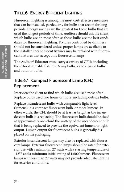
Aud
it, E
duc
atio
n,
Base
load
and
Hot
Wat
er
54
TITLE.6 ENERGY EFFICIENT LIGHTING Fluorescent lighting is among the most cost-effective measures that can be installed, particularly for bulbs that are on for long periods. Energy savings are the greatest for those bulbs that are used the longest periods of time. Auditors should ask the client which bulbs are on most often as those bulbs are the best candi-dates for fluorescent lighting. Fixtures controlled by dimmers should not be considered unless proper lamps are available to the installer. Incandescent fixtures may be replaced with fluores-cent fixtures that accept only fluorescent lamps.
The Auditor/ Educator must carry a variety of CFL’s, including those for dimmable fixtures, 3-way bulbs, candle based bulbs and outdoor bulbs.
Title.6.1 Compact Fluorescent Lamp (CFL) Replacement
Interview the client to find which bulbs are used most often. Replace bulbs used two hours or more, including outside bulbs.
Replace incandescent bulbs with comparable light level (lumens) in a compact fluorescent bulb, or more lumens. In other words, the CFL should be at least as bright as the incan-descent bulb it is replacing. The fluorescent bulb should be sized at approximately one-third the wattage of the incandescent bulb that is being replaced to provide the equivalent lumen, or light, output. Lumen output for fluorescent bulbs is generally dis-played on the packaging.
Exterior incandescent lamps may also be replaced with fluores-cent lamps. Exterior fluorescent lamps should be rated for exte-rior use with a minimum 27 watts with a starting temperature of -12°F and a minimum initial rating of 1,600 lumens. Fluorescent lamps with less than 27 watts may not provide adequate lighting for exterior conditions.
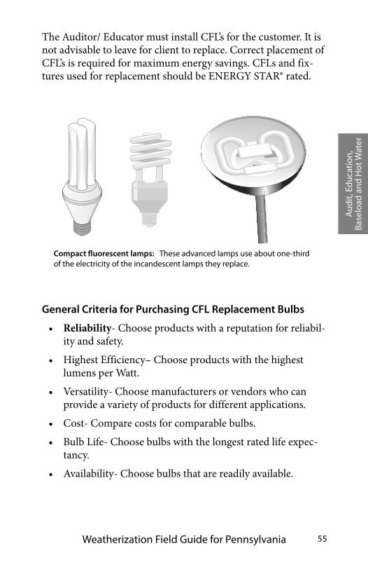
Aud
it, E
duc
atio
n,
Base
load
and
Hot
Wat
er
Weatherization Field Guide for Pennsylvania 55
The Auditor/ Educator must install CFL’s for the customer. It is not advisable to leave for client to replace. Correct placement of CFL’s is required for maximum energy savings. CFLs and fix-tures used for replacement should be ENERGY STAR® rated.
General Criteria for Purchasing CFL Replacement Bulbs
• Reliability- Choose products with a reputation for reliabil-ity and safety.
• Highest Efficiency– Choose products with the highest lumens per Watt.
• Versatility- Choose manufacturers or vendors who can provide a variety of products for different applications.
• Cost- Compare costs for comparable bulbs.
• Bulb Life- Choose bulbs with the longest rated life expec-tancy.
• Availability- Choose bulbs that are readily available.
Compact fluorescent lamps: These advanced lamps use about one-third of the electricity of the incandescent lamps they replace.

Aud
it, E
duc
atio
n,
Base
load
and
Hot
Wat
er
56
Title.6.2 Halogen Lamps
Halogen floor lamps operate at 300 to 500 watts and could be a fire hazard. These should be replaced in all instances for health and safety reasons and for the energy efficiency afforded by lower wattage fluorescent floor lamps. Deliver and install replacement lower watt fluorescent floor lamps (45 – 60 watts). A new lamp may be assembled and delivered by a Weatheriza-tion crew, contractor or Baseload Auditor.
Disposal of Halogen Floor Lamps
The halogen lamps must be disabled and removed from the property by the agency. The client must sign a release statement surrendering the old halogen floor lamp and giving permission to the agency to disable and remove from the property.
TITLE.7 CLOTHES DRYER IMPROVEMENTS
To minimize dryer time replace plastic flex dryer vent with rigid metal vent material not to exceed appliance manufacturer's specifications. As a fall back measure, vent material must not exceed 25 feet from the dryer location to outlet terminal with a reduction in maximum length of 5 feet for each 90 degree elbow and 2 feet for each 45 degree elbow. All joints must be taped and clamped, or snap locked. No screws are allowed.
If dryer is not vented, and the client uses the dryer, provide vent-ing to outside as health and safety item. An unvented dryer may contribute to moisture problems or dehumidifier use. In some cases, this will mean wiring a new 220V outlet (per NEC code) and/or moving the dryer to properly vent it to the outside.
Inspect the lint trap to insure that it is being cleaned regularly.
Ensuring a dryer has adequate supply air also minimizes drying time. While some units have air inlets on the side or back, many draw air in from under the dryer, which is held off the ground by adjustable legs. If those legs have been broken or removed,

Aud
it, E
duc
atio
n,
Base
load
and
Hot
Wat
er
Weatherization Field Guide for Pennsylvania 57
the dryer cannot draw in adequate air and clothes will take a long time to dry. Raise dryer above floor by adjusting legs or other means if air intake is from under the dryer and dryer cycles are lengthened by inadequate air supply.
Energy Education Topics
• Clean lint trap.
• Dry clothes outside when possible.
• Dry full loads of clothes.
• Remove snow from vent outlet.
• Ensure closure of vent damper.
TITLE.8 WATER HEATING MEASURES
Unsafe or leaking water heaters may be replaced with a sealed combustion, fossil fuel-fired, or electric water heater.
Hot water measures include the following.
• Combustion Safety Tests for gas, propane or oil water heat-ers.
• Install pressure and temperature relief valve and discharge pipe in none exists.
• Install an R-11 exterior insulation wrap (unless already well insulated or not recommended).
• Adjust temperature.
• Fix hot water leaks.
• Energy-saving showerheads.
• Install pipe insulation on all exposed hot water pipes and the first six feet of cold water pipes off the top of the water heater.
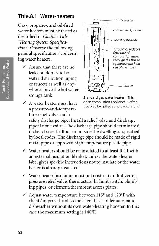
Aud
it, E
duc
atio
n,
Base
load
and
Hot
Wat
er
58
Title.8.1 Water-heaters
Gas-, propane-, and oil-fired water heaters must be tested as described in Chapter Title "Heating System Specifica-tions”.Observe the following general specifications concern-ing water heaters.
Assure that there are no leaks on domestic hot water distribution piping or faucets as well as any-where above the hot water storage tank.
A water heater must have a pressure-and-tempera-ture relief valve and a safety discharge pipe. Install a relief valve and discharge pipe if none exists. The discharge pipe should terminate 6 inches above the floor or outside the dwelling as specified by local codes. The discharge pipe should be made of rigid metal pipe or approved high temperature plastic pipe.
Water heaters should be re-insulated to at least R-11 with an external insulation blanket, unless the water-heater label gives specific instructions not to insulate or the water heater is already insulated.
Water heater insulation must not obstruct draft diverter, pressure relief valve, thermostats, hi-limit switch, plumb-ing pipes, or element/thermostat access plates.
Adjust water temperature between 115° and 120°F with clients’ approval, unless the client has a older automatic dishwasher without its own water-heating booster. In this case the maximum setting is 140°F.
Standard gas water heater: This open combustion appliance is often troubled by spillage and backdrafting.
draft diverter
burner
cold water dip tube
sacrificial anode
Turbulator reduces flow rate of combustion gases through the flue to squeeze more heat out of the gases
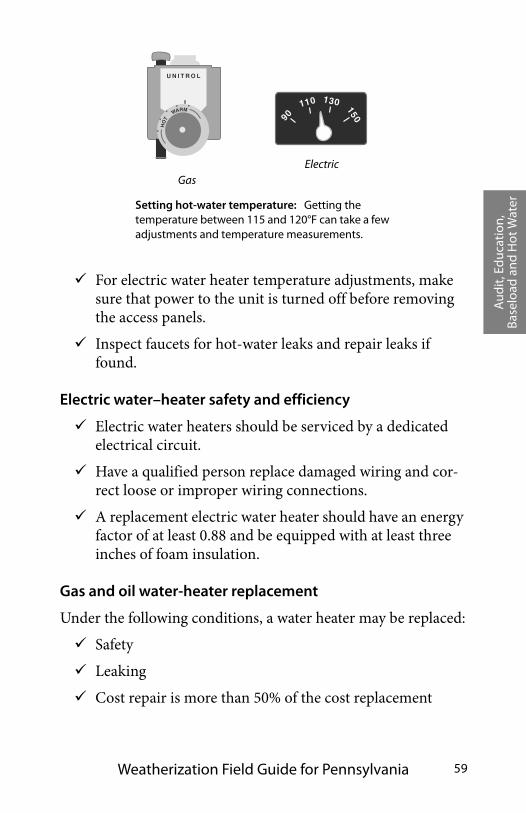
Aud
it, E
duc
atio
n,
Base
load
and
Hot
Wat
er
Weatherization Field Guide for Pennsylvania 59
For electric water heater temperature adjustments, make sure that power to the unit is turned off before removing the access panels.
Inspect faucets for hot-water leaks and repair leaks if found.
Electric water–heater safety and efficiency
Electric water heaters should be serviced by a dedicated electrical circuit.
Have a qualified person replace damaged wiring and cor-rect loose or improper wiring connections.
A replacement electric water heater should have an energy factor of at least 0.88 and be equipped with at least three inches of foam insulation.
Gas and oil water-heater replacement
Under the following conditions, a water heater may be replaced:
Safety
Leaking
Cost repair is more than 50% of the cost replacement
ElectricGas
U N I T R O L
HO
T
WARM
90
110 130 150
Setting hot-water temperature: Getting the temperature between 115 and 120°F can take a few adjustments and temperature measurements.
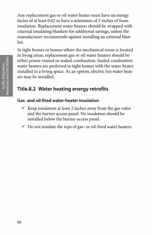
Aud
it, E
duc
atio
n,
Base
load
and
Hot
Wat
er
60
Any replacement gas or oil water heater must have an energy factor of at least 0.62 or have a minimum of 2 inches of foam insulation. Replacement water heaters should be wrapped with external insulating blankets for additional savings, unless the manufacturer recommends against installing an external blan-ket.
In tight homes or homes where the mechanical room is located in living areas, replacement gas or oil water heaters should be either power-vented or sealed-combustion. Sealed-combustion water heaters are preferred in tight homes with the water heater installed in a living space. As an option, electric hot water heat-ers may be installed.
Title.8.2 Water heating energy retrofits
Gas- and oil-fired water-heater insulation
Keep insulation at least 2 inches away from the gas valve and the burner access panel. No insulation should be installed below the burner access panel.
Do not insulate the tops of gas- or oil-fired water heaters.
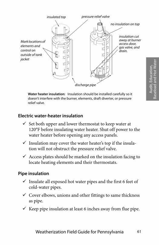
Aud
it, E
duc
atio
n,
Base
load
and
Hot
Wat
er
Weatherization Field Guide for Pennsylvania 61
Electric water-heater insulation
Set both upper and lower thermostat to keep water at 120°F before insulating water heater. Shut off power to the water heater before opening any access panels.
Insulation may cover the water heater’s top if the insula-tion will not obstruct the pressure relief valve.
Access plates should be marked on the insulation facing to locate heating elements and their thermostats.
Pipe insulation
Insulate all exposed hot water pipes and the first 6 feet of cold-water pipes.
Cover elbows, unions and other fittings to same thickness as pipe.
Keep pipe insulation at least 6 inches away from flue pipe.
pressure relief valveinsulated top
no insulation on top
Water heater insulation: Insulation should be installed carefully so it doesn’t interfere with the burner, elements, draft diverter, or pressure relief valve.
discharge pipe
insulation cut away at burner access door, gas valve, and drain.
Mark locations of elements and control on outside of tank jacket
Aud
it, E
duc
atio
n,
Base
load
and
Hot
Wat
er
62
Interior diameter of pipe insulation sleeve should match exterior diameter of pipe.
TITLE.9 OTHER BASELOAD USE
Other causes of high baseload use and seasonal baseload use should be identified and addressed through client education.
• Pump problems, such as sump pump or well pump that runs excessively.
• Secondary refrigerators or freezers.
• Unidentified space heaters.
• Clothes Dryers
• Phantom use; usually identifiable as excessive plug loads.
• Window air conditioning use.
• Dehumidifiers.
If you are unable to determine the cause of high baseload, refer the customer to their utility company. There are service repre-sentatives who can visit the house with testing equipment to troubleshoot mystery use. For example, they may test for an electric bleed-to-ground. See “Baseload Auditing Tools and Equipment” on page 247.
Hea
lth
and
Safe
ty
Weatherization Field Guide for Pennsylvania 63
CHAPTER TITLE: HEALTH AND SAFETY INFORMATION
This chapter explains some of the most pressing hazards that your clients face in their homes, as well as those you face at work as a weatherization specialist.
The most common home health hazards that are related to weatherization are:
1. Carbon monoxide
2. Moisture problems
3. Lead-based paint dust
4. Gas leaks
When a weatherization agency finds serious safety problems in a customer’s home, the agency should inform the customer in writing about the hazards and make suggestions about how to eliminate them.
The home is second only to the automobile as a dangerous place to be: household accidents kill 24,000 Americans and injure 3,500,000 each year. Children may be at a greater risk because they spend more time at home and are less aware of danger than adults. There are three major causes of non-workplace injuries.
1. Falls
2. Poisoning by solids and liquids
3. Smoke inhalation and burns from fires
See “Health and Safety Standards” on page 28.
TITLE.1 CLIENT HEALTH AND SAFETY
Carbon monoxide, moisture problems, lead-paint dust, and gas leaks are the most important health and safety problems related to weatherization work. When these are detected, inform the
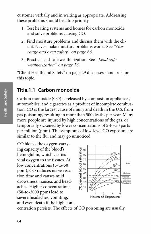
Hea
lth
and
Safe
ty
64
customer verbally and in writing as appropriate. Addressing these problems should be a top priority.
1. Test heating systems and homes for carbon monoxide and solve problems causing CO.
2. Find moisture problems and discuss them with the cli-ent. Never make moisture problems worse. See “Gas range and oven safety” on page 66.
3. Practice lead-safe weatherization. See “Lead-safe weatherization” on page 76.
“Client Health and Safety” on page 29 discusses standards for this topic.
Title.1.1 Carbon monoxide
Carbon monoxide (CO) is released by combustion appliances, automobiles, and cigarettes as a product of incomplete combus-tion. CO is the largest cause of injury and death in the U.S. from gas poisoning, resulting in more than 500 deaths per year. Many more people are injured by high concentrations of the gas, or temporarily sickened by lower concentrations of 5-to-50 parts per million (ppm). The symptoms of low-level CO exposure are similar to the flu, and may go unnoticed.
CO blocks the oxygen-carry-ing capacity of the blood’s hemoglobin, which carries vital oxygen to the tissues. At low concentrations (5-to-50 ppm), CO reduces nerve reac-tion time and causes mild drowsiness, nausea, and head-aches. Higher concentrations (50-to-3000 ppm) lead to severe headaches, vomiting, and even death if the high con-centration persists. The effects of CO poisoning are usually
10
20
30
40
50
60
70
80
90
1 2 3 4
Collapse
HeadacheDizziness
Impairedjudgement
Fatal
Hours of Exposure
CO
per
cen
t blo
od
satu
ratio
n
100
200
400
800
1600
3200
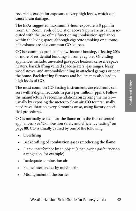
Hea
lth
and
Safe
ty
Weatherization Field Guide for Pennsylvania 65
reversible, except for exposure to very high levels, which can cause brain damage.
The EPA’s suggested maximum 8-hour exposure is 9 ppm in room air. Room levels of CO at or above 9 ppm are usually asso-ciated with the use of malfunctioning combustion appliances within the living space, although cigarette smoking or automo-bile exhaust are also common CO sources.
CO is a common problem in low-income housing, affecting 20% or more of residential buildings in some regions. Offending appliances include: unvented gas space heaters, kerosene space heaters, backdrafting vented space heaters, gas ranges, leaky wood stoves, and automobiles idling in attached garages or near the home. Backdrafting furnaces and boilers may also lead to high levels of CO.
The most common CO-testing instruments are electronic sen-sors with a digital readouts in parts per million (ppm). Follow the manufacturer’s recommendations on zeroing the meter—usually by exposing the meter to clean air. CO testers usually need re-calibration every 6 months or so, using factory-speci-fied procedures.
CO is normally tested near the flame or in the flue of vented appliances. See “Combustion safety and efficiency testing” on page 88. CO is usually caused by one of the following:
• Overfiring
• Backdrafting of combustion gases smothering the flame
• Flame interference by an object (a pan over a gas burner on a range top, for example)
• Inadequate combustion air
• Flame interference by moving air
• Misalignment of the burner
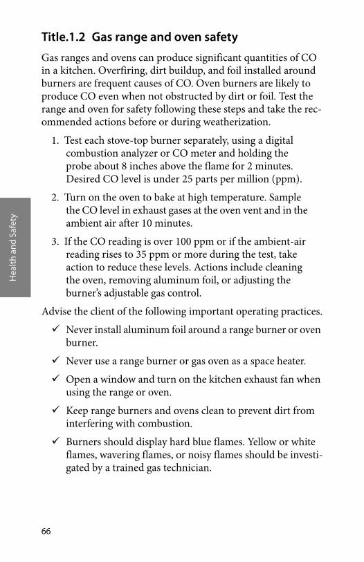
Hea
lth
and
Safe
ty
66
Title.1.2 Gas range and oven safety
Gas ranges and ovens can produce significant quantities of CO in a kitchen. Overfiring, dirt buildup, and foil installed around burners are frequent causes of CO. Oven burners are likely to produce CO even when not obstructed by dirt or foil. Test the range and oven for safety following these steps and take the rec-ommended actions before or during weatherization.
1. Test each stove-top burner separately, using a digital combustion analyzer or CO meter and holding the probe about 8 inches above the flame for 2 minutes. Desired CO level is under 25 parts per million (ppm).
2. Turn on the oven to bake at high temperature. Sample the CO level in exhaust gases at the oven vent and in the ambient air after 10 minutes.
3. If the CO reading is over 100 ppm or if the ambient-air reading rises to 35 ppm or more during the test, take action to reduce these levels. Actions include cleaning the oven, removing aluminum foil, or adjusting the burner’s adjustable gas control.
Advise the client of the following important operating practices.
Never install aluminum foil around a range burner or oven burner.
Never use a range burner or gas oven as a space heater.
Open a window and turn on the kitchen exhaust fan when using the range or oven.
Keep range burners and ovens clean to prevent dirt from interfering with combustion.
Burners should display hard blue flames. Yellow or white flames, wavering flames, or noisy flames should be investi-gated by a trained gas technician.
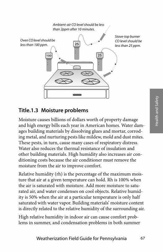
Hea
lth
and
Safe
ty
Weatherization Field Guide for Pennsylvania 67
Title.1.3 Moisture problems
Moisture causes billions of dollars worth of property damage and high energy bills each year in American homes. Water dam-ages building materials by dissolving glues and mortar, corrod-ing metal, and nurturing pests like mildew, mold and dust mites. These pests, in turn, cause many cases of respiratory distress. Water also reduces the thermal resistance of insulation and other building materials. High humidity also increases air con-ditioning costs because the air conditioner must remove the moisture from the air to improve comfort.
Relative humidity (rh) is the percentage of the maximum mois-ture that air at a given temperature can hold. Rh is 100% when the air is saturated with moisture. Add more moisture to satu-rated air, and water condenses on cool objects. Relative humid-ity is 50% when the air at a particular temperature is only half saturated with water vapor. Building materials’ moisture content is directly related to the relative humidity of the surrounding air.
High relative humidity in indoor air can cause comfort prob-lems in summer, and condensation problems in both summer
25100
25Oven CO level should be less than 100 ppm.
Ambient-air CO level should be less than 2ppm after 10 minutes.
Stove-top burner CO level should be less than 25 ppm.
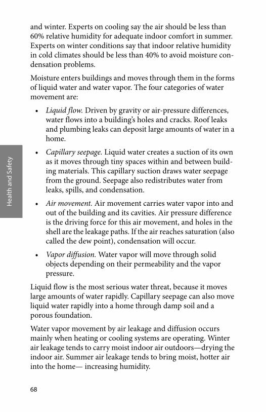
Hea
lth
and
Safe
ty
68
and winter. Experts on cooling say the air should be less than 60% relative humidity for adequate indoor comfort in summer. Experts on winter conditions say that indoor relative humidity in cold climates should be less than 40% to avoid moisture con-densation problems.
Moisture enters buildings and moves through them in the forms of liquid water and water vapor. The four categories of water movement are:
• Liquid flow. Driven by gravity or air-pressure differences, water flows into a building’s holes and cracks. Roof leaks and plumbing leaks can deposit large amounts of water in a home.
• Capillary seepage. Liquid water creates a suction of its own as it moves through tiny spaces within and between build-ing materials. This capillary suction draws water seepage from the ground. Seepage also redistributes water from leaks, spills, and condensation.
• Air movement. Air movement carries water vapor into and out of the building and its cavities. Air pressure difference is the driving force for this air movement, and holes in the shell are the leakage paths. If the air reaches saturation (also called the dew point), condensation will occur.
• Vapor diffusion. Water vapor will move through solid objects depending on their permeability and the vapor pressure.
Liquid flow is the most serious water threat, because it moves large amounts of water rapidly. Capillary seepage can also move liquid water rapidly into a home through damp soil and a porous foundation.
Water vapor movement by air leakage and diffusion occurs mainly when heating or cooling systems are operating. Winter air leakage tends to carry moist indoor air outdoors—drying the indoor air. Summer air leakage tends to bring moist, hotter air into the home— increasing humidity.

Hea
lth
and
Safe
ty
Weatherization Field Guide for Pennsylvania 69
Vapor diffusion is the slowest form of moisture movement and creates fewer problems than the others. However, vapor diffu-sion can cause condensation inside relatively cool building cavi-ties during both the heating and cooling seasons.
Moisture moves into a building during wet seasons and out dur-ing drier seasons. Moisture is a problem when it reaches a level that encourages pests—termites, dust mites, dry rot, and fungus.
The most common sources of moisture are leaky roofs and damp foundations. Other critical moisture sources include dry-ers vented to indoors, showers, cooking appliances, hanging wet laundry indoors, drying fire wood supply indoors, and unvented gas appliances like ranges or decorative fireplaces. Climate is also a major contributor to moisture problems. The more rain, extreme temperatures, and humid weather a region has, the more its homes are vulnerable to moisture problems.
Reducing sources of moisture is the first priority for solving moisture problems. Next most important are air and vapor bar-riers to prevent water-vapor from migrating through building cavities. Relatively airtight homes may need mechanical ventila-tion to remove accumulating water vapor. Also, see “Moisture Problems” on page 30.
soil moisture
oven & range
perspiration
showeringwasher & dryer
aquariumhumidifier
Moisture sources: Moisture sources abound in typical homes.

Hea
lth
and
Safe
ty
70
Symptoms of moisture problems
Condensation on windows, walls, and other surfaces signals high relative humidity and the need to find and reduce moisture sources. During very cold weather or rapid weather changes, condensation may occur. This occasional condensation isn’t a major problem. However, if window condensation is a persistent problem, reduce moisture sources, add insulation, or consider other remedies that lead to warmer interior surfaces. The colder the outdoor temperature, the more likely condensation is to occur. Adding insulation helps eliminate cold areas where water vapor condenses.
Moisture problems arise when the moisture content of building materials reaches a threshold where pests like termites, dust mites, rot, and fungus can thrive. Asthma, bronchitis and other respiratory ailments can be exacerbated by moisture problems because mold, mildew, and dust mites’ protein and feces are potent allergens.
Table Title-1:Typical Household Moisture Sources
Moisture SourcePotential Amount
Pints
Ground moisture 0–105 per day
Unvented combustion space heater 0.5 –20 per hour
Seasonal evaporation from materials 6–19 per day
Dryers venting indoors 4–6 per load
Dishwashing 1–2 per day
Cooking (meals for four) 2–4 per day
Showering 0.5 per shower
Hanging laundry to dry indoors 8-12 per day
Drying/seasoning fire wood indoors (one cord)
32 pints
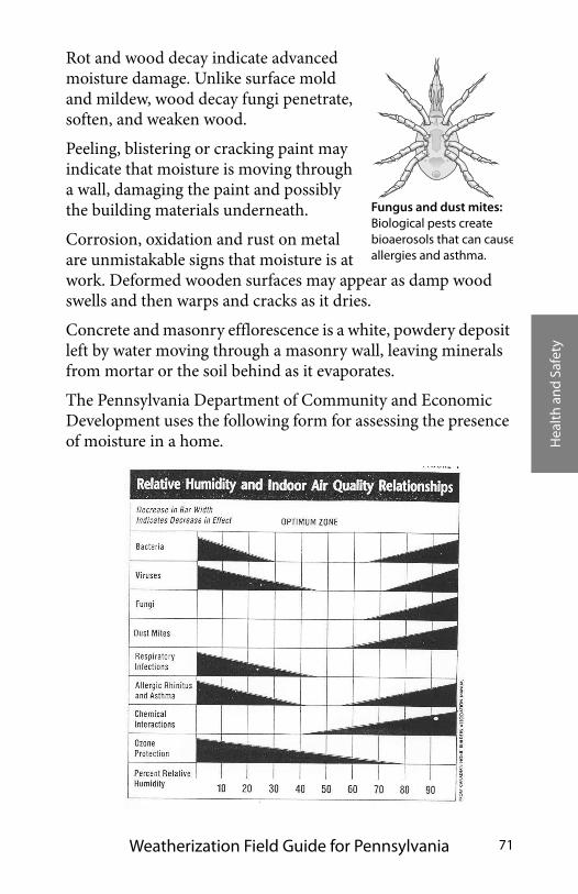
Hea
lth
and
Safe
ty
Weatherization Field Guide for Pennsylvania 71
Rot and wood decay indicate advanced moisture damage. Unlike surface mold and mildew, wood decay fungi penetrate, soften, and weaken wood.
Peeling, blistering or cracking paint may indicate that moisture is moving through a wall, damaging the paint and possibly the building materials underneath.
Corrosion, oxidation and rust on metal are unmistakable signs that moisture is at work. Deformed wooden surfaces may appear as damp wood swells and then warps and cracks as it dries.
Concrete and masonry efflorescence is a white, powdery deposit left by water moving through a masonry wall, leaving minerals from mortar or the soil behind as it evaporates.
The Pennsylvania Department of Community and Economic Development uses the following form for assessing the presence of moisture in a home.
Fungus and dust mites: Biological pests create bioaerosols that can causeallergies and asthma.
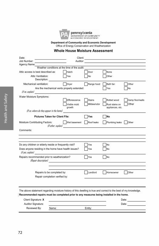
Hea
lth
and
Safe
ty
72
Date: Client:Job Number: Auditor:Agency Name
Attic access is best described as: Hatch Door None
Yes No OtherDescription:
Dryer Range hood Bath fan Other
Are the mechanical vents properly extended: Yes No(if no, explain)
Water Moisture Symptoms:Efflorescence Stains Rotted wood Damp floor/walls
Mildew/odor Other
Yes No
Moisture Contributing Factors: Wet basement Roof leaks Plumbing leaks Other
Visible mold growth
Rust stains on appliances, etc.
Department of Community and Economic DevelopmentOffice of Energy Conservation and Weatherization
Whole House Moisture Assessment
(If so, where do they appear in the home)
Weather conditions at the time of the audit:
Pictures Taken for Client File:
(If other, explain)
Attic Ventilation:
Mechanical ventilation:
Comments:
Do any children or elderly reside or frequently visit? Yes No
Does anyone residing in the home have health issues? Yes No(if yes, explain)
Repairs recommended prior to weatherization? Yes No
Repairs to be completed by: Landlord Homeowner Other
Repair completion verified by:
The above statement regarding moisture history of this dwelling is true and correct to the best of my knowledge.Recommended repairs must be completed prior to any measures being installed in the home.
:ytitnE:emaN
(Repair description)
Client Signature: X Date:
(If other, explain)
Reviewed By:Date:Auditor Signature:
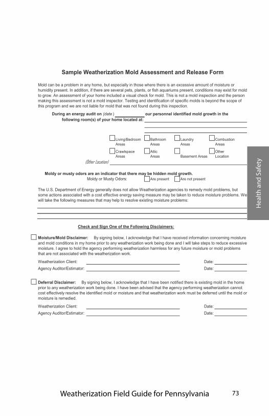
Hea
lth
and
Safe
ty
Weatherization Field Guide for Pennsylvania 73
our personnel identified mold growth in the
Moldy or musty odors are an indicator that there may be hidden mold growth. Moldy or Musty Odors: Are present Are not present
Mold can be a problem in any home, but especially in those where there is an excessive amount of moisture or humidity present. In addition, if there are several pets, plants, or fish aquariums present, conditions may exist for mold to grow. An assessment of your home included a visual check for mold. This is not a mold inspection and the person making this assessment is not a mold inspector. Testing and identification of specific molds is beyond the scope of this program and we are not liable for mold that was not found during this inspection.
During an energy audit on (date )following room(s) of your home located at:
Living/Bedroom Areas
Bathroom Areas
Combustion Areas
Laundry Areas
Crawlspace Areas
AtticAreas Basement Areas
Other Location
The U.S. Department of Energy generally does not allow Weatherization agencies to remedy mold problems, but some actions associated with a cost effective energy saving measure may be taken to reduce moisture problems. We will take the following measures that may help to resolve existing moisture problems:
Sample Weatherization Mold Assessment and Release Form
(Other Location)
Weatherization Client:Agency Auditor/Estimator:
Weatherization Client:Agency Auditor/Estimator:
Date:
Deferral Disclaimer: By signing below, I acknowledge that I have been notified there is existing mold in the home prior to any weatherization work being done. I have been advised that the agency performing weatherization cannot cost effectively resolve the identified mold or moisture and that weatherization work must be deferred until the mold or moisture is remedied.
Moisture/Mold Disclaimer: By signing below, I acknowledge that I have received information concerning moisture and mold conditions in my home prior to any weatherization work being done and I will take steps to reduce excessive moisture. I agree to hold the agency performing weatherization harmless for any future moisture or mold problems that are not associated with the weatherization work.
Date:
Check and Sign One of the Following Disclaimers:
Date:Date:
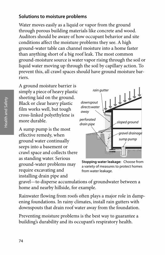
Hea
lth
and
Safe
ty
74
Solutions to moisture problems
Water moves easily as a liquid or vapor from the ground through porous building materials like concrete and wood. Auditors should be aware of how occupant behavior and site conditions affect the moisture problems they see. A high ground-water table can channel moisture into a home faster than anything short of a big roof leak. The most common ground-moisture source is water vapor rising through the soil or liquid water moving up through the soil by capillary action. To prevent this, all crawl spaces should have ground moisture bar-riers.
A ground moisture barrier is simply a piece of heavy plastic sheeting laid on the ground. Black or clear heavy plastic film works well, but tough cross-linked polyethylene is more durable.
A sump pump is the most effective remedy, when ground water continually seeps into a basement or crawl space and collects there as standing water. Serious ground-water problems may require excavating and installing drain pipe and gravel—to disperse accumulations of groundwater between a home and nearby hillside, for example.
Rainwater flowing from roofs often plays a major role in damp-ening foundations. In rainy climates, install rain gutters with downspouts that drain roof water away from the foundation.
Preventing moisture problems is the best way to guarantee a building’s durability and its occupant’s respiratory health.
Stopping water leakage: Choose from a variety of measures to protect homes from water leakage.
rain gutter
sloped ground
sump pump
perforated drain pipe
downspout directs water away
gravel drainage
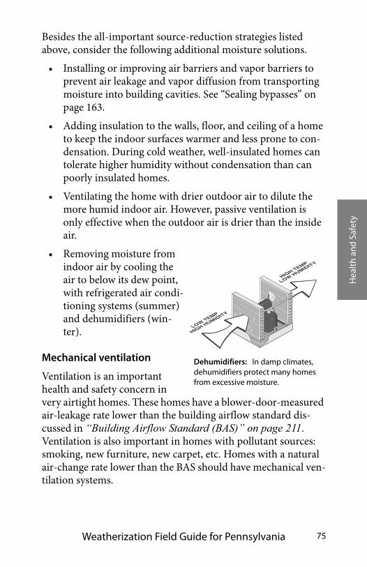
Hea
lth
and
Safe
ty
Weatherization Field Guide for Pennsylvania 75
Besides the all-important source-reduction strategies listed above, consider the following additional moisture solutions.
• Installing or improving air barriers and vapor barriers to prevent air leakage and vapor diffusion from transporting moisture into building cavities. See “Sealing bypasses” on page 163.
• Adding insulation to the walls, floor, and ceiling of a home to keep the indoor surfaces warmer and less prone to con-densation. During cold weather, well-insulated homes can tolerate higher humidity without condensation than can poorly insulated homes.
• Ventilating the home with drier outdoor air to dilute the more humid indoor air. However, passive ventilation is only effective when the outdoor air is drier than the inside air.
• Removing moisture from indoor air by cooling the air to below its dew point, with refrigerated air condi-tioning systems (summer) and dehumidifiers (win-ter).
Mechanical ventilation
Ventilation is an important health and safety concern in very airtight homes. These homes have a blower-door-measured air-leakage rate lower than the building airflow standard dis-cussed in “Building Airflow Standard (BAS)” on page 211. Ventilation is also important in homes with pollutant sources: smoking, new furniture, new carpet, etc. Homes with a natural air-change rate lower than the BAS should have mechanical ven-tilation systems.
Dehumidifiers: In damp climates, dehumidifiers protect many homes from excessive moisture.
LOW TEMP
HIGH HUMIDITY
HIGH TEMP
LOW HUMIDITY

Hea
lth
and
Safe
ty
76
The choice comes down to ventilating the whole house or pro-viding spot-ventilation in the kitchen and bathroom where most moisture and odors are generated. Kitchen and bath fans must be vented outdoors, never into crawl spaces or attics.
High quality exhaust fans should have tight-sealing backdraft dampers. Backdraft dampers are located in the fan housing, in the vent duct, or in the termination fitting in the roof or wall.
A low noise level (rated in sones) is important in encouraging occupants to use exhaust fans. The sone rating varies from about 5 sones for the noisiest residential exhaust fans to about 0.5 sones for the quietest fans. The success of spot ventilation and whole-house ventilation depends on how much noise the fan makes. Occupants may not use the fans or may disconnect auto-matic controls if the fans are too noisy.
Exhaust fans can also provide whole-house ventilation. Make-up air comes from outdoors through the home’s air leaks. Man-ual switches, dehumidistats, and timers are used to control exhaust fans for whole-house ventilation. Exhaust fans typically run from 2 to 6 hours per day, when providing whole-house ventilation.
Title.1.4 Lead-safe weatherization
All dust is dangerous, but lead dust is particularly dangerous because lead is a poison. Children are more vulnerable than adults because of their greater hand-to-mouth behavior. Take all necessary steps, outlined here, to protect customers and their children from lead dust.
Lead-safe weatherization (LSW) is a group of safe practices used by weatherization technicians. LSW practices are little more than very careful dust-prevention and housekeeping precau-tions. Lead-safe weatherization is required when workers will disturb painted surfaces by cutting, scraping, drilling, or other dust-creating activities.
Hea
lth
and
Safe
ty
Weatherization Field Guide for Pennsylvania 77
Technicians should assume the presence of lead based paints in any site built home constructed prior to 1978. Weatherization activities that could disturb lead paint and create lead dust include the following:
• Glazing, weatherstripping, or replacing windows
• Weatherstripping, repairing, or replacing doors
• Drilling holes in the interior or the exterior of the home for installing insulation
• Removing trim or cutting through walls or ceilings to seal air leaks, install ducts, replace windows etc.
• Removing painted siding for installing insulation
When engaging in these activities, follow DOE and EPA lead safe protocols.
Also, see “Lead-Based Paint Hazards” on page 32 and “Unvented Space Heaters” on page 25.
TITLE.2 WORKER HEALTH AND SAFETY
Injuries are the fourth leading cause of death in the United States. Long-term exposure to toxic materials contributes to sickness, absenteeism, and death of workers.
The personal health and safety of each employee is vitally important. Preventing injuries on the job is weatherization’s highest priority. Workplace safety standards established by the Occupational Safety and Health Administration (OSHA) as well as other standards established by the construction trade must be observed by weatherization staff and their contractors. Safety always has priority over other factors affecting weatherization operations. The following hazards merit special attention of weatherization agencies and their contractors because of their statistical importance.
1. Driving
2. Falls

Hea
lth
and
Safe
ty
78
3. Back injuries
4. Hazardous materials
5. Electrical and tool hazards
6. Repetitive stress injuries
“Crew or Contractor Health and Safety” on page 28 discusses standards for this topic.
Title.2.1 Commitment to safety
Workers tend to become complacent about their health and safety if its importance is not continually stressed. Weatheriza-tion agencies should do the following to encourage safety.
• Arrange regular health and safety training,
• Conduct regular safety meetings,
• Keep equipment in good condition, and
• Observe all state and federal standards relating to worker health and safety.
Safety requires communication and action. To protect them-selves from injury and illness, workers are encouraged to recog-nize hazards, communicate with co-workers and supervisors, and take action to reduce or eliminate hazards.
Safety meetings: Safety education and safety meetings are essential parts of a successful safety program.
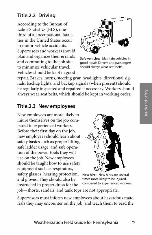
Hea
lth
and
Safe
ty
Weatherization Field Guide for Pennsylvania 79
Title.2.2 Driving
According to the Bureau of Labor Statistics (BLS), one-third of all occupational fatali-ties in the United States occur in motor-vehicle accidents. Supervisors and workers should plan and organize their errands and commuting to the job site to minimize vehicular travel. Vehicles should be kept in good repair. Brakes, horns, steering gear, headlights, directional sig-nals, backup lights, and backup signals (when present) should be regularly inspected and repaired if necessary. Workers should always wear seat belts, which should be kept in working order.
Title.2.3 New employees
New employees are more likely to injure themselves on the job com-pared to experienced workers. Before their first day on the job, new employees should learn about safety basics such as proper lifting, safe ladder usage, and safe opera-tion of the power tools they will use on the job. New employees should be taught how to use safety equipment such as respirators, safety glasses, hearing protection, and gloves. They should also be instructed in proper dress for the job—shorts, sandals, and tank tops are not appropriate.
Supervisors must inform new employees about hazardous mate-rials they may encounter on the job, and teach them to read the
Safe vehicles: Maintain vehicles in good repair. Drivers and passengers should always wear seat belts.
New hire: New hires are several times more likely to be injured, compared to experienced workers.
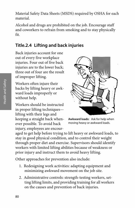
Hea
lth
and
Safe
ty
80
Material Safety Data Sheets (MSDS) required by OSHA for each material.
Alcohol and drugs are prohibited on the job. Encourage staff and coworkers to refrain from smoking and to stay physically fit.
Title.2.4 Lifting and back injuries
Back injuries account for one out of every five workplace injuries. Four out of five back injuries are to the lower back; three out of four are the result of improper lifting.
Workers often injure their backs by lifting heavy or awk-ward loads improperly or without help.
Workers should be instructed in proper lifting techniques—lifting with their legs and keeping a straight back when-ever possible. To avoid back injury, employees are encour-aged to get help before trying to lift heavy or awkward loads, to stay in good physical condition, and to control their weight through proper diet and exercise. Supervisors should identify workers with limited lifting abilities because of weakness or prior injury and instruct them to avoid heavy lifting.
Other approaches for prevention also include:
1. Redesigning work activities: adapting equipment and minimizing awkward movement on the job site.
2. Administrative controls: strength-testing workers, set-ting lifting limits, and providing training for all workers on the causes and prevention of back injuries.
Awkward loads: Ask for help when moving heavy or awkward loads.
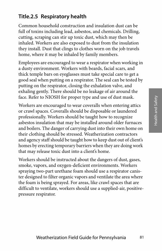
Hea
lth
and
Safe
ty
Weatherization Field Guide for Pennsylvania 81
Title.2.5 Respiratory health
Common household construction and insulation dust can be full of toxins including lead, asbestos, and chemicals. Drilling, cutting, scraping can stir up toxic dust, which may then be inhaled. Workers are also exposed to dust from the insulation they install. Dust that clings to clothes worn on the job travels home, where it may be inhaled by family members.
Employees are encouraged to wear a respirator when working in a dusty environment. Workers with beards, facial scars, and thick temple bars on eyeglasses must take special care to get a good seal when putting on a respirator. The seal can be tested by putting on the respirator, closing the exhalation valve, and exhaling gently. There should be no leakage of air around the face. Refer to NIOSH for proper type and use of dust mask.
Workers are encouraged to wear coveralls when entering attics or crawl spaces. Coveralls should be disposable or laundered professionally. Workers should be taught how to recognize asbestos insulation that may be installed around older furnaces and boilers. The danger of carrying dust into their own home on their clothing should be stressed. Weatherization contractors and agency staff should be taught how to keep dust out of client’s homes by erecting temporary barriers when they are doing work that may release toxic dust into a client’s home.
Workers should be instructed about the dangers of dust, gases, smoke, vapors, and oxygen-deficient environments. Workers spraying two-part urethane foam should use a respirator canis-ter designed to filter organic vapors and ventilate the area where the foam is being sprayed. For areas, like crawl spaces that are difficult to ventilate, workers should use a supplied-air, positive-pressure respirator.
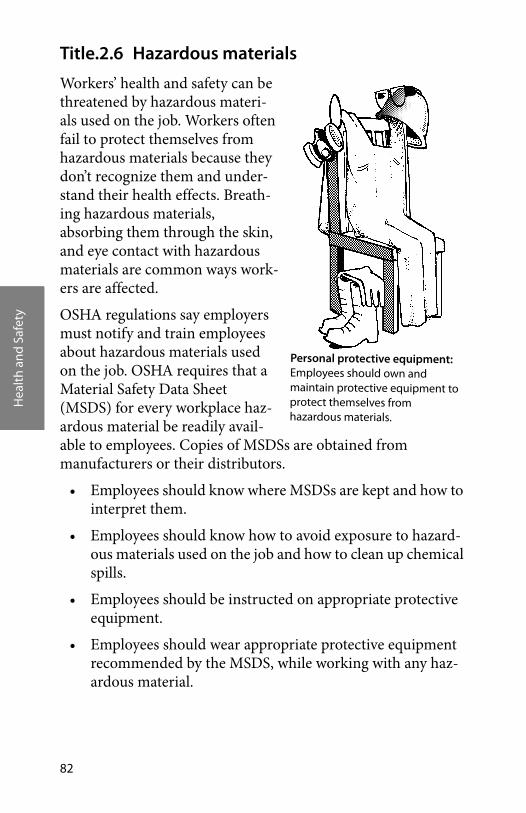
Hea
lth
and
Safe
ty
82
Title.2.6 Hazardous materials
Workers’ health and safety can be threatened by hazardous materi-als used on the job. Workers often fail to protect themselves from hazardous materials because they don’t recognize them and under-stand their health effects. Breath-ing hazardous materials, absorbing them through the skin, and eye contact with hazardous materials are common ways work-ers are affected.
OSHA regulations say employers must notify and train employees about hazardous materials used on the job. OSHA requires that a Material Safety Data Sheet (MSDS) for every workplace haz-ardous material be readily avail-able to employees. Copies of MSDSs are obtained from manufacturers or their distributors.
• Employees should know where MSDSs are kept and how to interpret them.
• Employees should know how to avoid exposure to hazard-ous materials used on the job and how to clean up chemical spills.
• Employees should be instructed on appropriate protective equipment.
• Employees should wear appropriate protective equipment recommended by the MSDS, while working with any haz-ardous material.
Personal protective equipment: Employees should own and maintain protective equipment to protect themselves from hazardous materials.
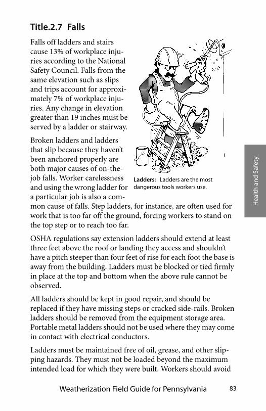
Hea
lth
and
Safe
ty
Weatherization Field Guide for Pennsylvania 83
Title.2.7 Falls
Falls off ladders and stairs cause 13% of workplace inju-ries according to the National Safety Council. Falls from the same elevation such as slips and trips account for approxi-mately 7% of workplace inju-ries. Any change in elevation greater than 19 inches must be served by a ladder or stairway.
Broken ladders and ladders that slip because they haven’t been anchored properly are both major causes of on-the-job falls. Worker carelessness and using the wrong ladder for a particular job is also a com-mon cause of falls. Step ladders, for instance, are often used for work that is too far off the ground, forcing workers to stand on the top step or to reach too far.
OSHA regulations say extension ladders should extend at least three feet above the roof or landing they access and shouldn’t have a pitch steeper than four feet of rise for each foot the base is away from the building. Ladders must be blocked or tied firmly in place at the top and bottom when the above rule cannot be observed.
All ladders should be kept in good repair, and should be replaced if they have missing steps or cracked side-rails. Broken ladders should be removed from the equipment storage area. Portable metal ladders should not be used where they may come in contact with electrical conductors.
Ladders must be maintained free of oil, grease, and other slip-ping hazards. They must not be loaded beyond the maximum intended load for which they were built. Workers should avoid
Ladders: Ladders are the most dangerous tools workers use.

Hea
lth
and
Safe
ty
84
carrying heavy loads up ladders and operating power tools from ladders.
Scaffolding must be used when working above-ground for sus-tained time periods. Scaffolds should be built plumb and level. Each leg should be stabilized so that it supports equal weight as other legs. This is especially important on unlevel ground. Planks should be secured to the structure and handrails pro-vided on the sides and ends of the walkway.
Workplaces should be policed regularly to remove slipping and tripping hazards. Workers carrying loads should establish a debris-free walkway.
Title.2.8 Repetitive Stress Injuries
Ergonomics establish good work habits in your office or on the job by the proper posture, hand and arm coordination in the use of tools or office equipment. It has been found that long term injuries can be avoided by stretching just a few minutes a day. As a result new designs are being made in hand and power tools, office equipment as well as every day home equipment uses. Your safety committee should have their ergonomics standard included for your own personal safety.
Title.2.9 Tool safety
The tools used in construction work are dangerous if used improperly. About 90,000 people hurt themselves with hand tools each year. One moment of inattention can cause an injury that can change a worker’s life permanently.
Good housekeeping: Good housekeeping is essential to protect workers and clients alike from falls.
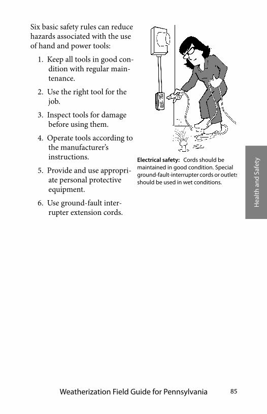
Hea
lth
and
Safe
ty
Weatherization Field Guide for Pennsylvania 85
Six basic safety rules can reduce hazards associated with the use of hand and power tools:
1. Keep all tools in good con-dition with regular main-tenance.
2. Use the right tool for the job.
3. Inspect tools for damage before using them.
4. Operate tools according to the manufacturer’s instructions.
5. Provide and use appropri-ate personal protective equipment.
6. Use ground-fault inter-rupter extension cords.
Electrical safety: Cords should be maintained in good condition. Special ground-fault-interrupter cords or outletsshould be used in wet conditions.

Hea
lth
and
Safe
ty
86
Hea
ting
Sys
tem
Sp
ecifi
cati
ons
Weatherization Field Guide for Pennsylvania 87
CHAPTER TITLE: HEATING SYSTEM SPECIFICATIONS
PA will elect to use the parameters set forth in its published set of PA Field Standards for Heating System Improvements. Com-bustion heating systems heat most homes and their operation generates many important topics. Combustion safety and effi-ciency lead off this chapter because they are the primary tests performed by an auditor. Chimneys, venting, and combustion air are the topics of the middle part of this chapter. Distribution systems, furnaces and boilers, and installation issues follow the sections on combustion.
Gas and oil combustion efficiency and safety are discussed in separate sections. Natural gas and propane systems are basically the same appliances, differing from one another only in operat-ing pressure and the orifice sizes of their burners. The word “gas” used here means either natural gas or propane.
Oil-fired appliances often operate significantly below their max-imum fuel-burning efficiency. Adjusting fuel-air mixture, draft, as well as, cleaning the burner and heat exchanger can often boost efficiency noticeably.
Gas furnaces and boilers burn cleanly in comparison to heaters powered by other fuels. The fuel-burning efficiency of gas appli-ances is difficult to improve, although removing carbon monox-ide (CO) from their combustion gases makes them operate more safely.
Forced-air furnaces are the most common type of heating sys-tem. Leaky ducts and airflow problems are common problems with furnaces and ducts. This chapter discusses furnaces and ducts in sections: “Furnace operating standards” on page 133, “Duct air-tightness standards” on page 135, and “Improving duct-system airflow” on page 139.
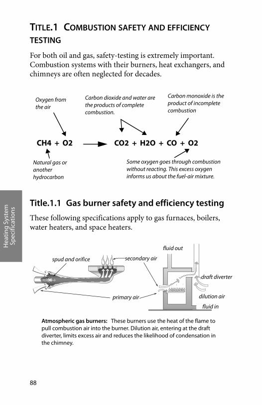
Hea
ting
Sys
tem
Sp
ecifi
cati
ons
88
TITLE.1 COMBUSTION SAFETY AND EFFICIENCY TESTING
For both oil and gas, safety-testing is extremely important. Combustion systems with their burners, heat exchangers, and chimneys are often neglected for decades.
Title.1.1 Gas burner safety and efficiency testing
These following specifications apply to gas furnaces, boilers, water heaters, and space heaters.
CH4 + O2 CO2 + H2O + CO + O2
Some oxygen goes through combustion without reacting. This excess oxygen informs us about the fuel-air mixture.
Carbon dioxide and water are the products of complete combustion.
Carbon monoxide is the product of incomplete combustion
Natural gas or another hydrocarbon
Oxygen from the air
primary air
secondary air
dilution air
draft diverter
fluid in
fluid out
spud and orifice
Atmospheric gas burners: These burners use the heat of the flame to pull combustion air into the burner. Dilution air, entering at the draft diverter, limits excess air and reduces the likelihood of condensation in the chimney.
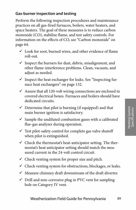
Hea
ting
Sys
tem
Sp
ecifi
cati
ons
Weatherization Field Guide for Pennsylvania 89
Gas-burner inspection and testing
Perform the following inspection procedures and maintenance practices on all gas-fired furnaces, boilers, water heaters, and space heaters. The goal of these measures is to reduce carbon monoxide (CO), stabilize flame, and test safety controls. For information on the effects of CO, see “Carbon monoxide” on page 64.
Look for soot, burned wires, and other evidence of flame roll-out.
Inspect the burners for dust, debris, misalignment, and other flame-interference problems. Clean, vacuum, and adjust as needed.
Inspect the heat exchanger for leaks. See “Inspecting fur-nace heat exchangers” on page 132.
Assure that all 120-volt wiring connections are enclosed in covered electrical boxes. Furnaces and boilers should have dedicated circuits.
Determine that pilot is burning (if equipped) and that main burner ignition is satisfactory.
Sample the undiluted combustion gases with a calibrated flue-gas analyzer during operation.
Test pilot-safety control for complete gas valve shutoff when pilot is extinguished.
Check the thermostat’s heat-anticipator setting. The ther-mostat’s heat anticipator setting should match the mea-sured current in the 24-volt control circuit.
Check venting system for proper size and pitch.
Check venting system for obstructions, blockages, or leaks.
Measure chimney draft downstream of the draft diverter.
Drill and non-corrosive plug in PVC vent for sampling hole on Category IV vent.
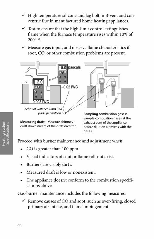
Hea
ting
Sys
tem
Sp
ecifi
cati
ons
90
High temperature silicone and lag bolt in B-vent and con-centric flue in manufactured home heating appliances.
Test to ensure that the high-limit control extinguishes flame when the furnace temperature rises within 10% of 200° F.
Measure gas input, and observe flame characteristics if soot, CO, or other combustion problems are present.
Proceed with burner maintenance and adjustment when:
• CO is greater than 100 ppm.
• Visual indicators of soot or flame roll-out exist.
• Burners are visibly dirty.
• Measured draft is low or nonexistent.
• The appliance doesn’t conform to the combustion specifi-cations above.
Gas-burner maintenance includes the following measures.
Remove causes of CO and soot, such as over-firing, closed primary air intake, and flame impingement.
–0.008 IWC
–0.02 IWC
pascals B A
A B
B A
A B
–5.0
–2.0 ���
Sampling combustion gases: Sample combustion gases at the exhaust vent of the appliance before dilution air mixes with the gases.
Measuring draft: Measure chimney draft downstream of the draft diverter.
inches of water column (IWC)parts per million CO
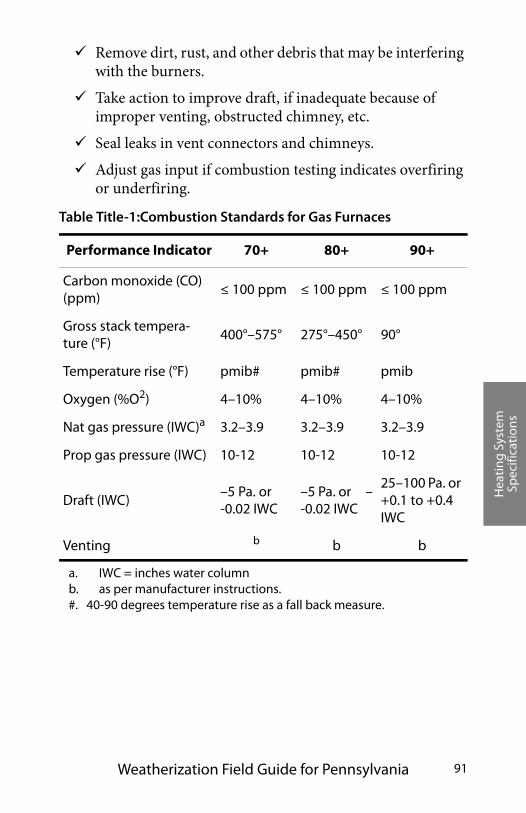
Hea
ting
Sys
tem
Sp
ecifi
cati
ons
Weatherization Field Guide for Pennsylvania 91
Remove dirt, rust, and other debris that may be interfering with the burners.
Take action to improve draft, if inadequate because of improper venting, obstructed chimney, etc.
Seal leaks in vent connectors and chimneys.
Adjust gas input if combustion testing indicates overfiring or underfiring.
Table Title-1:Combustion Standards for Gas Furnaces
Performance Indicator 70+ 80+ 90+
Carbon monoxide (CO) (ppm)
≤ 100 ppm ≤ 100 ppm ≤ 100 ppm
Gross stack tempera-ture (°F)
400°–575° 275°–450° 90°
Temperature rise (°F) pmib# pmib# pmib
Oxygen (%O2) 4–10% 4–10% 4–10%
Nat gas pressure (IWC)a
a. IWC = inches water column
3.2–3.9 3.2–3.9 3.2–3.9
Prop gas pressure (IWC) 10-12 10-12 10-12
Draft (IWC)–5 Pa. or -0.02 IWC
–5 Pa. or –-0.02 IWC
25–100 Pa. or +0.1 to +0.4 IWC
Venting b
b. as per manufacturer instructions.#. 40-90 degrees temperature rise as a fall back measure.
b b
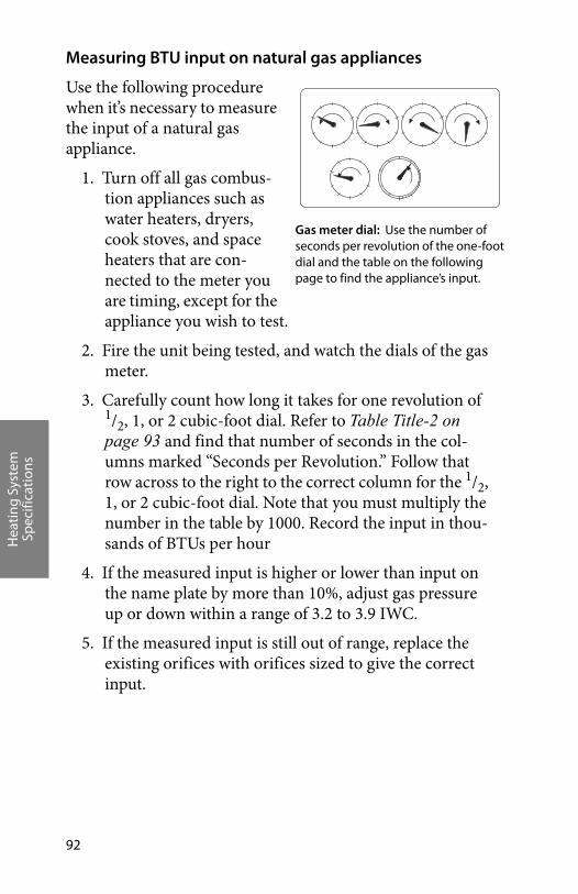
Hea
ting
Sys
tem
Sp
ecifi
cati
ons
92
Measuring BTU input on natural gas appliances
Use the following procedure when it’s necessary to measure the input of a natural gas appliance.
1. Turn off all gas combus-tion appliances such as water heaters, dryers, cook stoves, and space heaters that are con-nected to the meter you are timing, except for the appliance you wish to test.
2. Fire the unit being tested, and watch the dials of the gas meter.
3. Carefully count how long it takes for one revolution of 1/2, 1, or 2 cubic-foot dial. Refer to Table Title-2 on page 93 and find that number of seconds in the col-umns marked “Seconds per Revolution.” Follow that row across to the right to the correct column for the 1/2, 1, or 2 cubic-foot dial. Note that you must multiply the number in the table by 1000. Record the input in thou-sands of BTUs per hour
4. If the measured input is higher or lower than input on the name plate by more than 10%, adjust gas pressure up or down within a range of 3.2 to 3.9 IWC.
5. If the measured input is still out of range, replace the existing orifices with orifices sized to give the correct input.
�
�
����
�
��
� �
�
�� �
��
�
��
��
�� � �
�
�
�� �
�
��
���
�
��
�� � �
� � �
� � ����� ��� �� � � � � �
���� �� � � � � �
� � �� � � � � � �
� � ��
�� � �
Gas meter dial: Use the number of seconds per revolution of the one-foot dial and the table on the following page to find the appliance’s input.
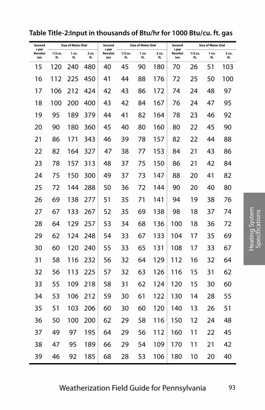
Hea
ting
Sys
tem
Sp
ecifi
cati
ons
Weatherization Field Guide for Pennsylvania 93
Table Title-2:Input in thousands of Btu/hr for 1000 Btu/cu. ft. gas
Seconds per
Revolution
Size of Meter Dial Seconds per
Revolution
Size of Meter Dial Seconds per
Revolution
Size of Meter Dial
1/2 cu. ft.
1 cu. ft.
2 cu. ft.
1/2 cu. ft.
1 cu. ft.
2 cu. ft.
1/2 cu. ft.
1 cu. ft.
2 cu. ft.
15 120 240 480 40 45 90 180 70 26 51 103
16 112 225 450 41 44 88 176 72 25 50 100
17 106 212 424 42 43 86 172 74 24 48 97
18 100 200 400 43 42 84 167 76 24 47 95
19 95 189 379 44 41 82 164 78 23 46 92
20 90 180 360 45 40 80 160 80 22 45 90
21 86 171 343 46 39 78 157 82 22 44 88
22 82 164 327 47 38 77 153 84 21 43 86
23 78 157 313 48 37 75 150 86 21 42 84
24 75 150 300 49 37 73 147 88 20 41 82
25 72 144 288 50 36 72 144 90 20 40 80
26 69 138 277 51 35 71 141 94 19 38 76
27 67 133 267 52 35 69 138 98 18 37 74
28 64 129 257 53 34 68 136 100 18 36 72
29 62 124 248 54 33 67 133 104 17 35 69
30 60 120 240 55 33 65 131 108 17 33 67
31 58 116 232 56 32 64 129 112 16 32 64
32 56 113 225 57 32 63 126 116 15 31 62
33 55 109 218 58 31 62 124 120 15 30 60
34 53 106 212 59 30 61 122 130 14 28 55
35 51 103 206 60 30 60 120 140 13 26 51
36 50 100 200 62 29 58 116 150 12 24 48
37 49 97 195 64 29 56 112 160 11 22 45
38 47 95 189 66 29 54 109 170 11 21 42
39 46 92 185 68 28 53 106 180 10 20 40

Hea
ting
Sys
tem
Sp
ecifi
cati
ons
94
Title.1.2 Leak-testing gas piping
Natural gas and propane piping systems may leak at their joints and valves. Find gas leaks with an electronic combustible-gas detector, often called a gas sniffer. A gas sniffer will find all sig-nificant gas leaks if used carefully. Remember that natural gas rises from a leak and propane falls, so position the sensor accordingly.
Sniff all valves and joints with the gas sniffer.
Accurately locate leaks using a non-corrosive bubbling liq-uid, designed for finding gas leaks.
All gas leaks should be repaired.
Title.1.3 Oil-burner safety and efficiency
Oil burners require annual maintenance to retain their opera-tional safety and combustion efficiency. Testing for combustion efficiency (steady-state efficiency), draft, carbon monoxide, and smoke should be used to guide and evaluate maintenance. These procedures pertain to oil-fired furnaces, boilers, and water heat-ers.
Oil-burner inspection and testing
Use visual inspection and combustion testing to evaluate oil burner operation. An oil burner passing visual inspection and giving good test results may need no maintenance. If the test results are outside of weatherization specifications, adjustments may be necessary (i.e. air band adjustments or retention head adjustments).
Follow these steps to achieve a minimum standard for oil-burner safety and efficiency:
Inspect burner and appliance for signs of soot, overheat-ing, fire hazards, or wiring problems.
Hea
ting
Sys
tem
Sp
ecifi
cati
ons
Weatherization Field Guide for Pennsylvania 95
Verify that all oil-fired heaters are equipped with a baro-metric draft control, unless they have high-static burners or are manufactured house furnaces.
Assure that all 120-volt wiring connections are enclosed in covered electrical boxes. Each oil furnace or boiler should have a dedicated electrical circuit.
Inspect fuel lines and storage tanks for leaks.
Inspect heat exchanger and combustion chamber for cracks, corrosion, or soot buildup.
Check to see if flame ignition is instantaneous or delayed. Flame ignition should be instantaneous, except for pre-purge units where the burner blower runs for a while before ignition.
Sample undiluted flue gases with a smoke tester, following the smoke-tester instructions. Compare the smoke spot left by the gases on the filter paper with the manufacturer’s smoke-spot scale to determine smoke number. If the smoke number is above 2, clean and tune. Perform a com-bustion analysis test.
Analyze the flue gas for O2 or CO2, temperature, CO, and steady-state efficiency (SSE). Sample undiluted flue gases between the barometric draft control and the appliance.
Measure flue draft between the appliance and barometric draft control and over-fire draft over the fire inside the firebox.
Measure high-limit shut-off temperature and adjust or replace the high-limit control if the shut-off temperature is more than 200° F for furnaces, or 180° F for hot-water boilers without a domestic coil. For hot-water boilers with a domestic coil, set the shut-off temperature as needed for domestic hot-water needs.
Measure transformer voltage, and replace if under specifi-cation (check input voltage first).
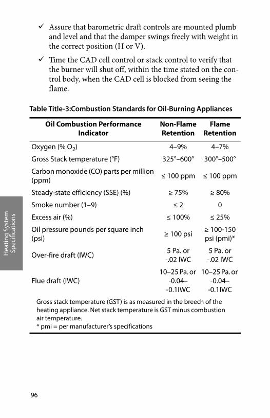
Hea
ting
Sys
tem
Sp
ecifi
cati
ons
96
Assure that barometric draft controls are mounted plumb and level and that the damper swings freely with weight in the correct position (H or V).
Time the CAD cell control or stack control to verify that the burner will shut off, within the time stated on the con-trol body, when the CAD cell is blocked from seeing the flame.
Table Title-3:Combustion Standards for Oil-Burning Appliances
Oil Combustion Performance Indicator
Non-Flame Retention
Flame Retention
Oxygen (% O2) 4–9% 4–7%
Gross Stack temperature (°F) 325°–600° 300°–500°
Carbon monoxide (CO) parts per million (ppm)
≤ 100 ppm ≤ 100 ppm
Steady-state efficiency (SSE) (%) ≥ 75% ≥ 80%
Smoke number (1–9) ≤ 2 0
Excess air (%) ≤ 100% ≤ 25%
Oil pressure pounds per square inch (psi)
≥ 100 psi ≥ 100-150 psi (pmi)*
Over-fire draft (IWC)5 Pa. or -.02 IWC
5 Pa. or -.02 IWC
Flue draft (IWC)10–25 Pa. or
-0.04–-0.1IWC
10–25 Pa. or -0.04–
-0.1IWC
Gross stack temperature (GST) is as measured in the breech of the heating appliance. Net stack temperature is GST minus combustion air temperature.* pmi = per manufacturer’s specifications
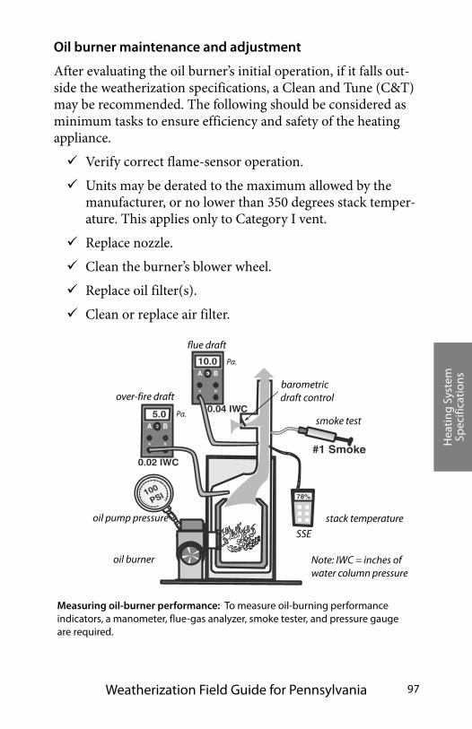
Hea
ting
Sys
tem
Sp
ecifi
cati
ons
Weatherization Field Guide for Pennsylvania 97
Oil burner maintenance and adjustment
After evaluating the oil burner’s initial operation, if it falls out-side the weatherization specifications, a Clean and Tune (C&T) may be recommended. The following should be considered as minimum tasks to ensure efficiency and safety of the heating appliance.
Verify correct flame-sensor operation.
Units may be derated to the maximum allowed by the manufacturer, or no lower than 350 degrees stack temper-ature. This applies only to Category I vent.
Replace nozzle.
Clean the burner’s blower wheel.
Replace oil filter(s).
Clean or replace air filter.
#1 Smoke
100
PSI
0.02 IWC
B A
A B
B A
A B
78%
10.0
5.0 0.04 IWC
Measuring oil-burner performance: To measure oil-burning performance indicators, a manometer, flue-gas analyzer, smoke tester, and pressure gauge are required.
barometric draft control
oil burner
over-fire draft
flue draft
SSE
oil pump pressure stack temperature
smoke test
Note: IWC = inches of water column pressure
Pa.
Pa.
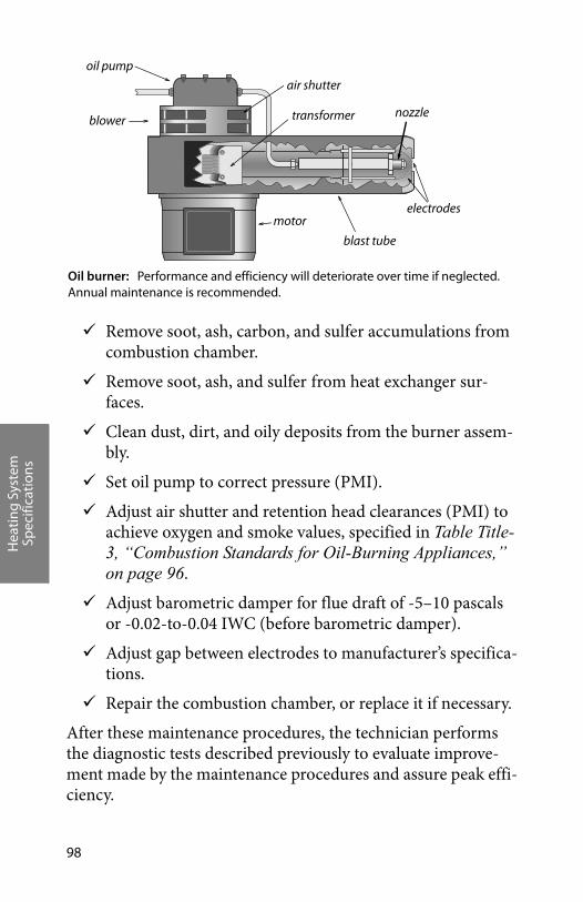
Hea
ting
Sys
tem
Sp
ecifi
cati
ons
98
Remove soot, ash, carbon, and sulfer accumulations from combustion chamber.
Remove soot, ash, and sulfer from heat exchanger sur-faces.
Clean dust, dirt, and oily deposits from the burner assem-bly.
Set oil pump to correct pressure (PMI).
Adjust air shutter and retention head clearances (PMI) to achieve oxygen and smoke values, specified in Table Title-3, “Combustion Standards for Oil-Burning Appliances,” on page 96.
Adjust barometric damper for flue draft of -5–10 pascals or -0.02-to-0.04 IWC (before barometric damper).
Adjust gap between electrodes to manufacturer’s specifica-tions.
Repair the combustion chamber, or replace it if necessary.
After these maintenance procedures, the technician performs the diagnostic tests described previously to evaluate improve-ment made by the maintenance procedures and assure peak effi-ciency.
nozzle
oil pump
motorelectrodes
air shutter
blower transformer
Oil burner: Performance and efficiency will deteriorate over time if neglected. Annual maintenance is recommended.
blast tube
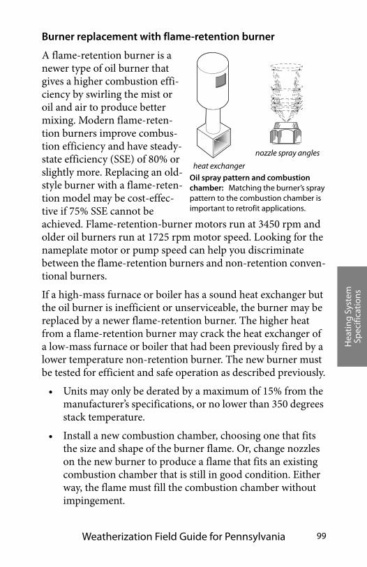
Hea
ting
Sys
tem
Sp
ecifi
cati
ons
Weatherization Field Guide for Pennsylvania 99
Burner replacement with flame-retention burner
A flame-retention burner is a newer type of oil burner that gives a higher combustion effi-ciency by swirling the mist or oil and air to produce better mixing. Modern flame-reten-tion burners improve combus-tion efficiency and have steady-state efficiency (SSE) of 80% or slightly more. Replacing an old-style burner with a flame-reten-tion model may be cost-effec-tive if 75% SSE cannot be achieved. Flame-retention-burner motors run at 3450 rpm and older oil burners run at 1725 rpm motor speed. Looking for the nameplate motor or pump speed can help you discriminate between the flame-retention burners and non-retention conven-tional burners.
If a high-mass furnace or boiler has a sound heat exchanger but the oil burner is inefficient or unserviceable, the burner may be replaced by a newer flame-retention burner. The higher heat from a flame-retention burner may crack the heat exchanger of a low-mass furnace or boiler that had been previously fired by a lower temperature non-retention burner. The new burner must be tested for efficient and safe operation as described previously.
• Units may only be derated by a maximum of 15% from the manufacturer’s specifications, or no lower than 350 degrees stack temperature.
• Install a new combustion chamber, choosing one that fits the size and shape of the burner flame. Or, change nozzles on the new burner to produce a flame that fits an existing combustion chamber that is still in good condition. Either way, the flame must fill the combustion chamber without impingement.
��
��
��������
heat exchanger
nozzle spray angles
Oil spray pattern and combustion chamber: Matching the burner’s spray pattern to the combustion chamber is important to retrofit applications.
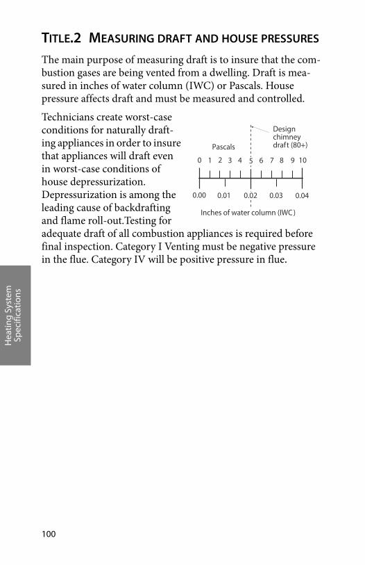
Hea
ting
Sys
tem
Sp
ecifi
cati
ons
100
TITLE.2 MEASURING DRAFT AND HOUSE PRESSURES
The main purpose of measuring draft is to insure that the com-bustion gases are being vented from a dwelling. Draft is mea-sured in inches of water column (IWC) or Pascals. House pressure affects draft and must be measured and controlled.
Technicians create worst-case conditions for naturally draft-ing appliances in order to insure that appliances will draft even in worst-case conditions of house depressurization. Depressurization is among the leading cause of backdrafting and flame roll-out.Testing for adequate draft of all combustion appliances is required before final inspection. Category I Venting must be negative pressure in the flue. Category IV will be positive pressure in flue.
109876543210
0.040.030.020.010.00
Pascals
Inches of water column (IWC )
Designchimneydraft (80+)
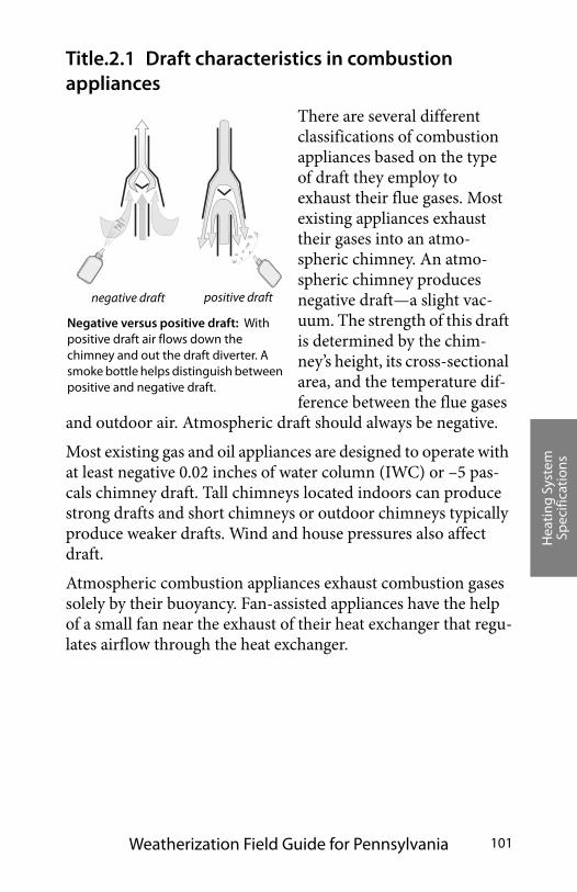
Hea
ting
Sys
tem
Sp
ecifi
cati
ons
Weatherization Field Guide for Pennsylvania 101
Title.2.1 Draft characteristics in combustion appliances
There are several different classifications of combustion appliances based on the type of draft they employ to exhaust their flue gases. Most existing appliances exhaust their gases into an atmo-spheric chimney. An atmo-spheric chimney produces negative draft—a slight vac-uum. The strength of this draft is determined by the chim-ney’s height, its cross-sectional area, and the temperature dif-ference between the flue gases
and outdoor air. Atmospheric draft should always be negative.
Most existing gas and oil appliances are designed to operate with at least negative 0.02 inches of water column (IWC) or –5 pas-cals chimney draft. Tall chimneys located indoors can produce strong drafts and short chimneys or outdoor chimneys typically produce weaker drafts. Wind and house pressures also affect draft.
Atmospheric combustion appliances exhaust combustion gases solely by their buoyancy. Fan-assisted appliances have the help of a small fan near the exhaust of their heat exchanger that regu-lates airflow through the heat exchanger.
Negative versus positive draft: With positive draft air flows down the chimney and out the draft diverter. A smoke bottle helps distinguish between positive and negative draft.
positive draftnegative draft
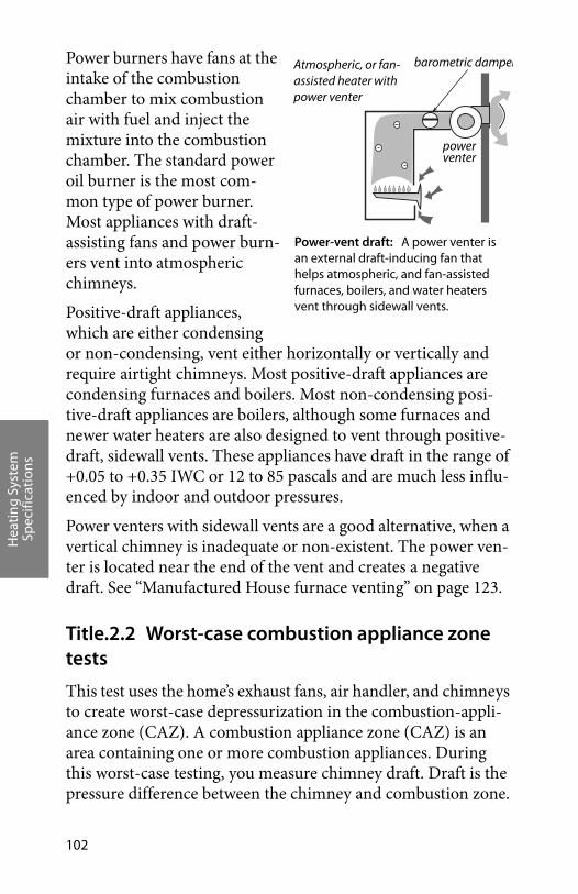
Hea
ting
Sys
tem
Sp
ecifi
cati
ons
102
Power burners have fans at the intake of the combustion chamber to mix combustion air with fuel and inject the mixture into the combustion chamber. The standard power oil burner is the most com-mon type of power burner. Most appliances with draft-assisting fans and power burn-ers vent into atmospheric chimneys.
Positive-draft appliances, which are either condensing or non-condensing, vent either horizontally or vertically and require airtight chimneys. Most positive-draft appliances are condensing furnaces and boilers. Most non-condensing posi-tive-draft appliances are boilers, although some furnaces and newer water heaters are also designed to vent through positive-draft, sidewall vents. These appliances have draft in the range of +0.05 to +0.35 IWC or 12 to 85 pascals and are much less influ-enced by indoor and outdoor pressures.
Power venters with sidewall vents are a good alternative, when a vertical chimney is inadequate or non-existent. The power ven-ter is located near the end of the vent and creates a negative draft. See “Manufactured House furnace venting” on page 123.
Title.2.2 Worst-case combustion appliance zone tests
This test uses the home’s exhaust fans, air handler, and chimneys to create worst-case depressurization in the combustion-appli-ance zone (CAZ). A combustion appliance zone (CAZ) is an area containing one or more combustion appliances. During this worst-case testing, you measure chimney draft. Draft is the pressure difference between the chimney and combustion zone.
Atmospheric, or fan-assisted heater with power venter
barometric damper
power
Power-vent draft: A power venter is an external draft-inducing fan that helps atmospheric, and fan-assisted furnaces, boilers, and water heaters vent through sidewall vents.
venter
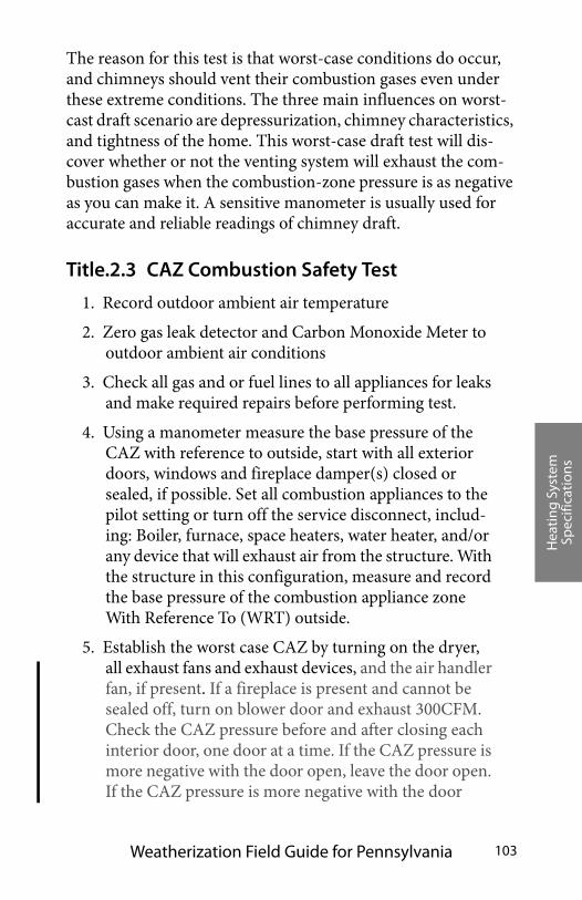
Hea
ting
Sys
tem
Sp
ecifi
cati
ons
Weatherization Field Guide for Pennsylvania 103
The reason for this test is that worst-case conditions do occur, and chimneys should vent their combustion gases even under these extreme conditions. The three main influences on worst-cast draft scenario are depressurization, chimney characteristics, and tightness of the home. This worst-case draft test will dis-cover whether or not the venting system will exhaust the com-bustion gases when the combustion-zone pressure is as negative as you can make it. A sensitive manometer is usually used for accurate and reliable readings of chimney draft.
Title.2.3 CAZ Combustion Safety Test
1. Record outdoor ambient air temperature
2. Zero gas leak detector and Carbon Monoxide Meter to outdoor ambient air conditions
3. Check all gas and or fuel lines to all appliances for leaks and make required repairs before performing test.
4. Using a manometer measure the base pressure of the CAZ with reference to outside, start with all exterior doors, windows and fireplace damper(s) closed or sealed, if possible. Set all combustion appliances to the pilot setting or turn off the service disconnect, includ-ing: Boiler, furnace, space heaters, water heater, and/or any device that will exhaust air from the structure. With the structure in this configuration, measure and record the base pressure of the combustion appliance zone With Reference To (WRT) outside.
5. Establish the worst case CAZ by turning on the dryer, all exhaust fans and exhaust devices, and the air handler fan, if present. If a fireplace is present and cannot be sealed off, turn on blower door and exhaust 300CFM. Check the CAZ pressure before and after closing each interior door, one door at a time. If the CAZ pressure is more negative with the door open, leave the door open. If the CAZ pressure is more negative with the door
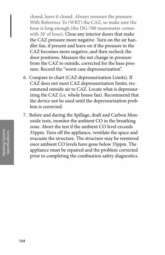
Hea
ting
Sys
tem
Sp
ecifi
cati
ons
104
closed, leave it closed. Always measure the pressure With Reference To (WRT) the CAZ, so make sure the hose is long enough (the DG-700 manometer comes with 30' of hose). Close any interior doors that make the CAZ pressure more negative. Turn on the air han-dler fan, if present and leave on if the pressure in the CAZ becomes more negative, and then recheck the door positions. Measure the net change in pressure from the CAZ to outside, corrected for the base pres-sure. Record the “worst case depressurization”.
6. Compare to chart (CAZ depressurization Limits). If CAZ does not meet CAZ depressurization limits, rec-ommend outside air to CAZ. Locate what is depressur-izing the CAZ (i.e. whole house fan). Recommend that the device not be used until the depressurization prob-lem is corrected.
7. Before and during the Spillage, draft and Carbon Mon-oxide tests, monitor the ambient CO in the breathing zone. Abort the test if the ambient CO level exceeds 35ppm. Turn off the appliance, ventilate the space and evacuate the structure. The structure may be reentered once ambient CO levels have gone below 35ppm. The appliance must be repaired and the problem corrected prior to completing the combustion safety diagnostics.
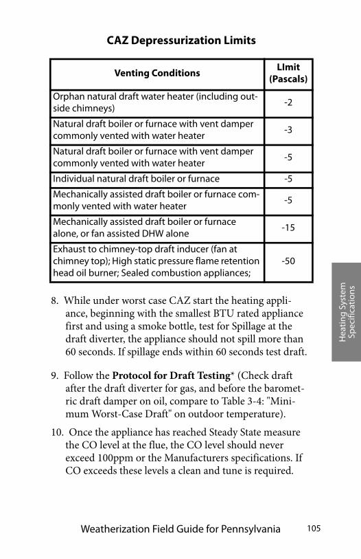
Hea
ting
Sys
tem
Sp
ecifi
cati
ons
Weatherization Field Guide for Pennsylvania 105
8. While under worst case CAZ start the heating appli-ance, beginning with the smallest BTU rated appliance first and using a smoke bottle, test for Spillage at the draft diverter, the appliance should not spill more than 60 seconds. If spillage ends within 60 seconds test draft.
9. Follow the Protocol for Draft Testing* (Check draft after the draft diverter for gas, and before the baromet-ric draft damper on oil, compare to Table 3-4: "Mini-mum Worst-Case Draft" on outdoor temperature).
10. Once the appliance has reached Steady State measure the CO level at the flue, the CO level should never exceed 100ppm or the Manufacturers specifications. If CO exceeds these levels a clean and tune is required.
CAZ Depressurization Limits
Venting ConditionsLImit
(Pascals)
Orphan natural draft water heater (including out-side chimneys)
-2
Natural draft boiler or furnace with vent damper commonly vented with water heater
-3
Natural draft boiler or furnace with vent damper commonly vented with water heater
-5
Individual natural draft boiler or furnace -5
Mechanically assisted draft boiler or furnace com-monly vented with water heater
-5
Mechanically assisted draft boiler or furnace alone, or fan assisted DHW alone
-15
Exhaust to chimney-top draft inducer (fan at chimney top); High static pressure flame retention head oil burner; Sealed combustion appliances;
-50
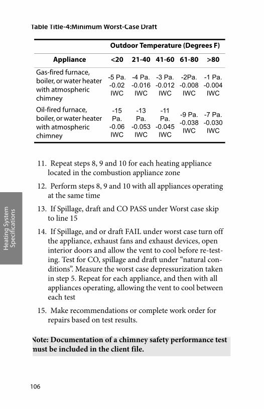
Hea
ting
Sys
tem
Sp
ecifi
cati
ons
106
11. Repeat steps 8, 9 and 10 for each heating appliance located in the combustion appliance zone
12. Perform steps 8, 9 and 10 with all appliances operating at the same time
13. If Spillage, draft and CO PASS under Worst case skip to line 15
14. If Spillage, and or draft FAIL under worst case turn off the appliance, exhaust fans and exhaust devices, open interior doors and allow the vent to cool before re-test-ing. Test for CO, spillage and draft under “natural con-ditions”. Measure the worst case depressurization taken in step 5. Repeat for each appliance, and then with all appliances operating, allowing the vent to cool between each test
15. Make recommendations or complete work order for repairs based on test results.
Table Title-4:Minimum Worst-Case Draft
Outdoor Temperature (Degrees F)
Appliance <20 21-40 41-60 61-80 >80
Gas-fired furnace, boiler, or water heater with atmospheric chimney
-5 Pa.-0.02IWC
-4 Pa.-0.016IWC
-3 Pa.-0.012IWC
-2Pa.-0.008IWC
-1 Pa.-0.004IWC
Oil-fired furnace, boiler, or water heater with atmospheric chimney
-15 Pa.
-0.06IWC
-13 Pa.
-0.053IWC
-11 Pa.
-0.045IWC
-9 Pa.-0.038IWC
-7 Pa.-0.030IWC
Note: Documentation of a chimney safety performance test must be included in the client file.

Hea
ting
Sys
tem
Sp
ecifi
cati
ons
Weatherization Field Guide for Pennsylvania 107
Title.2.4 * Protocol for Draft Testing
Measure flue pressure at steady-state operating conditions of all heating and hot water combustion appliances.
Gas appliances
1. Atmospheric or Natural Draft (70%): Draft testing shall be done in the center of the longest, straightest, accessi-ble section of the vent connector after the draft diverter. Holes made for the purpose of measuring draft shall be drilled using 5/16th bit. Once test is complete, seal hole with High Temperature RTV silicone caulk, cover with aluminum tape or metal plug.
2. Induced Draft (80%) furnaces: Draft testing shall be done downstream of the inducer motor. The preferred location for CO testing is the same hole used for draft testing. Holes made for Draft and CO testing shall be drilled using a 5/16th bit. Once test is complete, seal hole with High Temperature RTV silicone caulk, cover with aluminum tape or metal plug. If using B-vent completely seal the inner liner with High Temperature RTV silicone caulk and a 3/8 inch tap bolt made of stainless steel or seal interior hole with RTV silicone and cover exterior hole with aluminum tape.
3. Sealed Combustion or Power Vented appliances or water heaters (90% +): No draft measurement required, unless venting issues are suspected.
Oil appliances
Natural draft oil fired hot air, hot water, steam boilers and oil fired water heaters, measure draft at or in the breech or at the stack pipe (properly, just above the flue vent connector) mea-sured just a few inches above the boiler or furnace top, and before the barometric damper itself and no closer than 2 pipe sizes in diameter from any elbow. Drill a 5/16” hole in the flue
Hea
ting
Sys
tem
Sp
ecifi
cati
ons
108
gas exhaust pipe and seal hole with High Temperature RTV sili-cone caulk, cover with aluminum tape or metal plug.
Title.2.5 Improving inadequate draft
If measured draft is below minimum draft pressures, investigate the reason for the weak draft. Open a window or door to observe whether the addition of combustion air will improve draft. If this added air strengthens draft, the problem usually is depressurization. If opening a window has no effect, inspect the chimney. The chimney could be blocked or excessively leaky. Consider implementing the following improvements in order to solve draft problems.
Chimney improvements
Repair or remove chimney obstructions, disconnections, or leaks, which can weaken draft.
Measure the size of the vent connector and chimney and compare to vent-sizing information listed in Section 504 of the International Fuel Gas Code. A vent connector or chimney liner that is either too large or too small can result in poor draft.
If wind is causing erratic draft, consider a wind-dampen-ing chimney cap.
If the masonry chimney is deteriorated, consider installing a new chimney liner. See “Metal liners for masonry chim-neys” on page 115.
Duct improvements
Repair and seal return-duct leaks near furnace.
Isolate furnace from return registers by air-sealing.
Improve balance between supply and return air by install-ing new return ducts, transfer grills, or jumper ducts. See“Improving duct-system airflow” on page 139.
Hea
ting
Sys
tem
Sp
ecifi
cati
ons
Weatherization Field Guide for Pennsylvania 109
Reducing depressurization from exhaust devices
Isolate furnace from exhaust fans and clothes dryers by air-sealing between the combustion zone and zones con-taining these depressurizing forces.
Reduce capacity of large exhaust fans.
Combustion and make-up air
Provide make-up air for dryers and exhaust fans.
Provide combustion-air inlet to combustion zone. See “Combustion air” on page 126.
TITLE.3 VENTING COMBUSTION GASES
Proper venting is essential to the operation, efficiency, safety and durability of combustion heaters. Reference the most strin-gent code. The National Fire Protection Association (NFPA) and the International Code Council (ICC) are the authoritative information sources on material-choice, sizing, and clearances for chimneys and vent connectors, as well as for combustion air. The information in this venting section is based on the follow-ing NFPA and ICC documents.
• The National Fuel Gas Code (NFPA 54) (ANSI Z223.1) 2006 Edition
• NFPA 31: Standard for the Installation of Oil-Burning Equipment 2006 Edition
• NFPA 211: Standard for Chimneys, Fireplaces, Vents, and Solid-Fuel-Burning Appliances 2006 Edition
• The International Mechanical Code (IMC) 2009 edition
• The International Residential Code (IRC) 2009 edition
Title.3.1 General venting requirements
Combustion gases are vented through vertical chimneys or
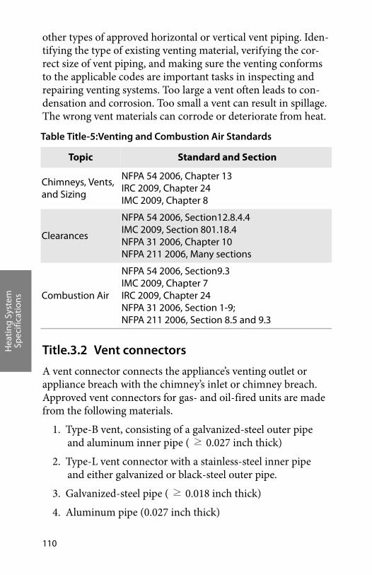
Hea
ting
Sys
tem
Sp
ecifi
cati
ons
110
other types of approved horizontal or vertical vent piping. Iden-tifying the type of existing venting material, verifying the cor-rect size of vent piping, and making sure the venting conforms to the applicable codes are important tasks in inspecting and repairing venting systems. Too large a vent often leads to con-densation and corrosion. Too small a vent can result in spillage. The wrong vent materials can corrode or deteriorate from heat.
Title.3.2 Vent connectors
A vent connector connects the appliance’s venting outlet or appliance breach with the chimney’s inlet or chimney breach. Approved vent connectors for gas- and oil-fired units are made from the following materials.
1. Type-B vent, consisting of a galvanized-steel outer pipe and aluminum inner pipe ( ≥ 0.027 inch thick)
2. Type-L vent connector with a stainless-steel inner pipe and either galvanized or black-steel outer pipe.
3. Galvanized-steel pipe ( ≥ 0.018 inch thick)
4. Aluminum pipe (0.027 inch thick)
Table Title-5:Venting and Combustion Air Standards
Topic Standard and Section
Chimneys, Vents, and Sizing
NFPA 54 2006, Chapter 13IRC 2009, Chapter 24IMC 2009, Chapter 8
Clearances
NFPA 54 2006, Section12.8.4.4IMC 2009, Section 801.18.4NFPA 31 2006, Chapter 10NFPA 211 2006, Many sections
Combustion Air
NFPA 54 2006, Section9.3IMC 2009, Chapter 7IRC 2009, Chapter 24NFPA 31 2006, Section 1-9; NFPA 211 2006, Section 8.5 and 9.3
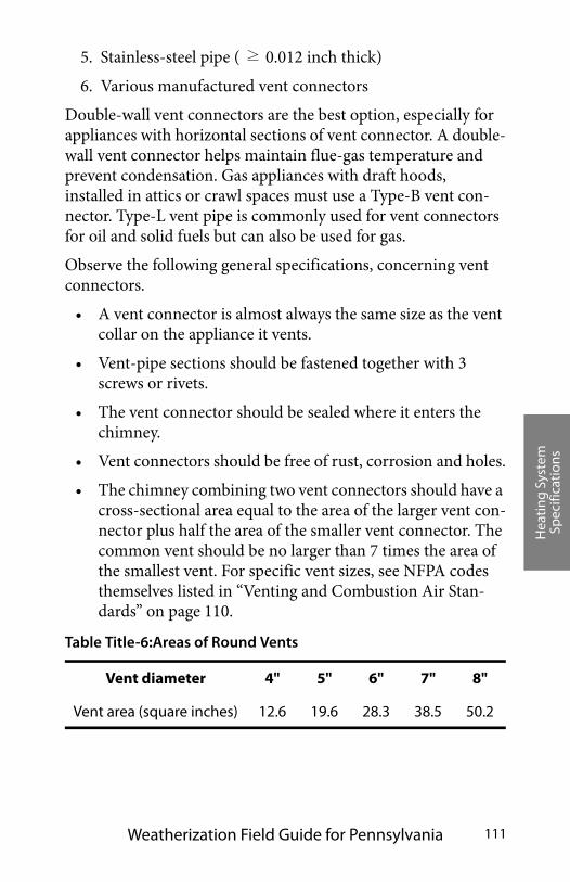
Hea
ting
Sys
tem
Sp
ecifi
cati
ons
Weatherization Field Guide for Pennsylvania 111
5. Stainless-steel pipe ( ≥ 0.012 inch thick)
6. Various manufactured vent connectors
Double-wall vent connectors are the best option, especially for appliances with horizontal sections of vent connector. A double-wall vent connector helps maintain flue-gas temperature and prevent condensation. Gas appliances with draft hoods, installed in attics or crawl spaces must use a Type-B vent con-nector. Type-L vent pipe is commonly used for vent connectors for oil and solid fuels but can also be used for gas.
Observe the following general specifications, concerning vent connectors.
• A vent connector is almost always the same size as the vent collar on the appliance it vents.
• Vent-pipe sections should be fastened together with 3 screws or rivets.
• The vent connector should be sealed where it enters the chimney.
• Vent connectors should be free of rust, corrosion and holes.
• The chimney combining two vent connectors should have a cross-sectional area equal to the area of the larger vent con-nector plus half the area of the smaller vent connector. The common vent should be no larger than 7 times the area of the smallest vent. For specific vent sizes, see NFPA codes themselves listed in “Venting and Combustion Air Stan-dards” on page 110.
Table Title-6:Areas of Round Vents
Vent diameter 4" 5" 6" 7" 8"
Vent area (square inches) 12.6 19.6 28.3 38.5 50.2
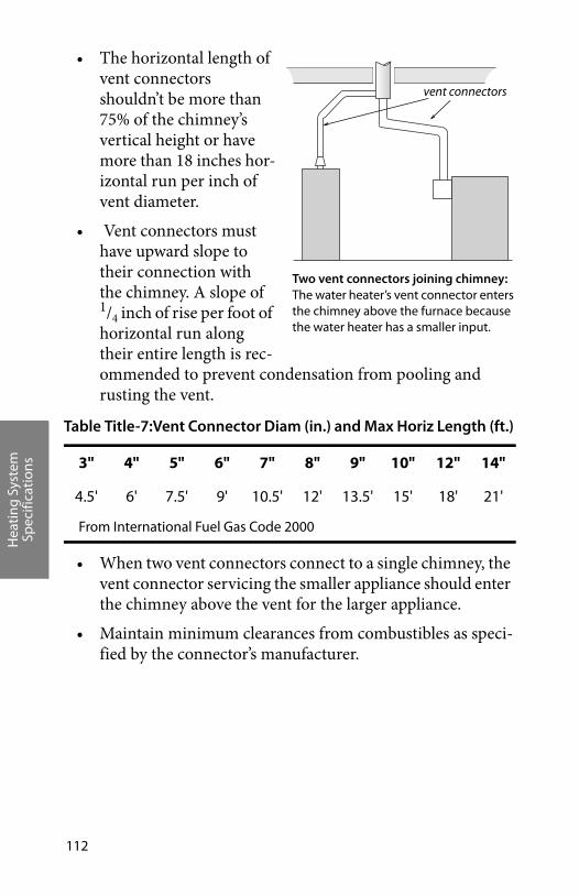
Hea
ting
Sys
tem
Sp
ecifi
cati
ons
112
• The horizontal length of vent connectors shouldn’t be more than 75% of the chimney’s vertical height or have more than 18 inches hor-izontal run per inch of vent diameter.
• Vent connectors must have upward slope to their connection with the chimney. A slope of 1/4 inch of rise per foot of horizontal run along their entire length is rec-ommended to prevent condensation from pooling and rusting the vent.
• When two vent connectors connect to a single chimney, the vent connector servicing the smaller appliance should enter the chimney above the vent for the larger appliance.
• Maintain minimum clearances from combustibles as speci-fied by the connector’s manufacturer.
Table Title-7:Vent Connector Diam (in.) and Max Horiz Length (ft.)
3" 4" 5" 6" 7" 8" 9" 10" 12" 14"
4.5' 6' 7.5' 9' 10.5' 12' 13.5' 15' 18' 21'
From International Fuel Gas Code 2000
Two vent connectors joining chimney: The water heater’s vent connector enters the chimney above the furnace because the water heater has a smaller input.
vent connectors
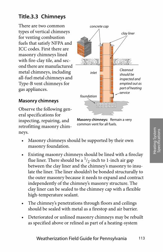
Hea
ting
Sys
tem
Sp
ecifi
cati
ons
Weatherization Field Guide for Pennsylvania 113
Title.3.3 Chimneys
There are two common types of vertical chimneys for venting combustion fuels that satisfy NFPA and ICC codes. First there are masonry chimneys lined with fire-clay tile, and sec-ond there are manufactured metal chimneys, including all-fuel metal chimneys and Type-B vent chimneys for gas appliances.
Masonry chimneys
Observe the following gen-eral specifications for inspecting, repairing, and retrofitting masonry chim-neys.
• Masonry chimneys should be supported by their own masonry foundation.
• Existing masonry chimneys should be lined with a fireclay flue liner. There should be a 1/2-inch to 1-inch air gap between the clay liner and the chimney’s masonry to insu-late the liner. The liner shouldn’t be bonded structurally to the outer masonry because it needs to expand and contract independently of the chimney’s masonry structure. The clay liner can be sealed to the chimney cap with a flexible high-temperature sealant.
• The chimney’s penetrations through floors and ceilings should be sealed with metal as a firestop and air barrier.
• Deteriorated or unlined masonry chimneys may be rebuilt as specified above or relined as part of a heating-system
concrete cap
clay liner
foundation
inlet
Masonry chimneys: Remain a very common vent for all fuels.
Cleanout should be inspected and emptied out as part of heating service
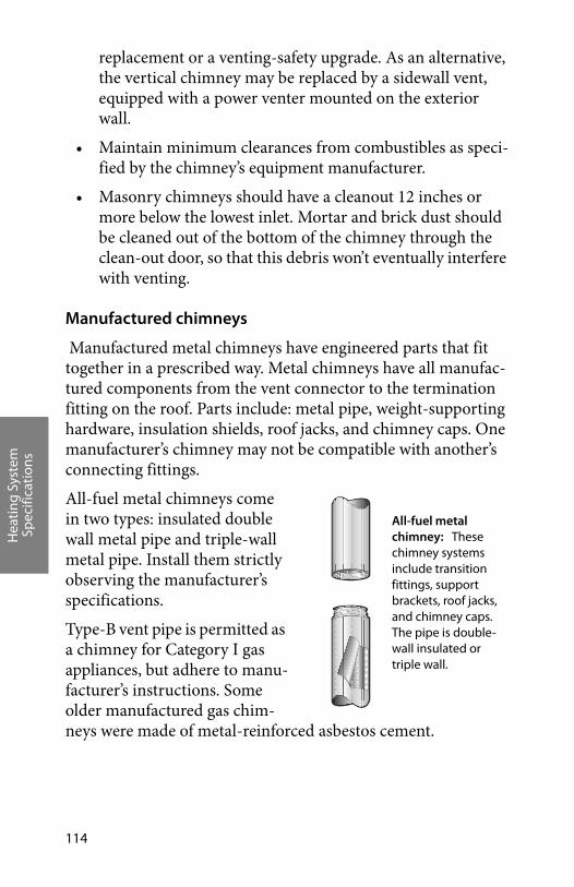
Hea
ting
Sys
tem
Sp
ecifi
cati
ons
114
replacement or a venting-safety upgrade. As an alternative, the vertical chimney may be replaced by a sidewall vent, equipped with a power venter mounted on the exterior wall.
• Maintain minimum clearances from combustibles as speci-fied by the chimney’s equipment manufacturer.
• Masonry chimneys should have a cleanout 12 inches or more below the lowest inlet. Mortar and brick dust should be cleaned out of the bottom of the chimney through the clean-out door, so that this debris won’t eventually interfere with venting.
Manufactured chimneys
Manufactured metal chimneys have engineered parts that fit together in a prescribed way. Metal chimneys have all manufac-tured components from the vent connector to the termination fitting on the roof. Parts include: metal pipe, weight-supporting hardware, insulation shields, roof jacks, and chimney caps. One manufacturer’s chimney may not be compatible with another’s connecting fittings.
All-fuel metal chimneys come in two types: insulated double wall metal pipe and triple-wall metal pipe. Install them strictly observing the manufacturer’s specifications.
Type-B vent pipe is permitted as a chimney for Category I gas appliances, but adhere to manu-facturer’s instructions. Some older manufactured gas chim-neys were made of metal-reinforced asbestos cement.
All-fuel metal chimney: These chimney systems include transition fittings, support brackets, roof jacks, and chimney caps. The pipe is double-wall insulated or triple wall.
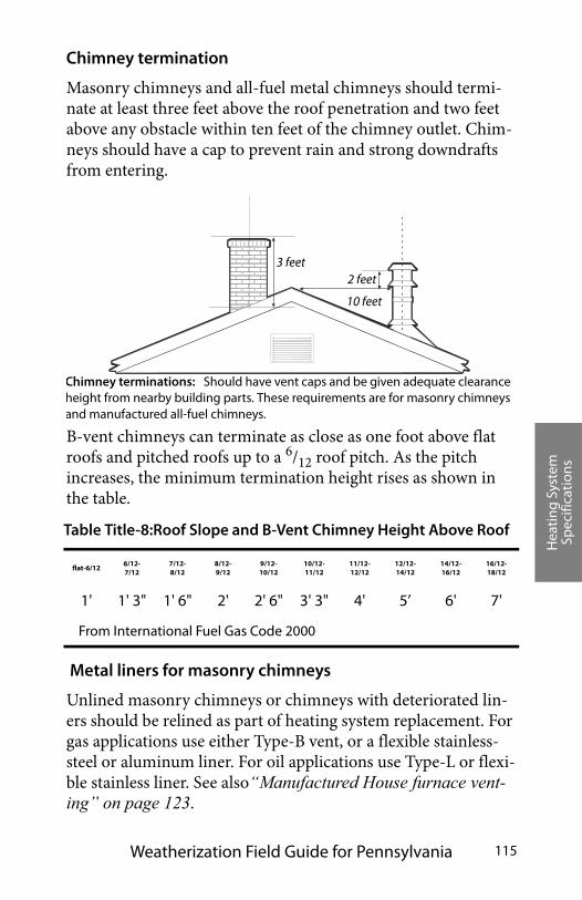
Hea
ting
Sys
tem
Sp
ecifi
cati
ons
Weatherization Field Guide for Pennsylvania 115
Chimney termination
Masonry chimneys and all-fuel metal chimneys should termi-nate at least three feet above the roof penetration and two feet above any obstacle within ten feet of the chimney outlet. Chim-neys should have a cap to prevent rain and strong downdrafts from entering.
B-vent chimneys can terminate as close as one foot above flat roofs and pitched roofs up to a 6/12 roof pitch. As the pitch increases, the minimum termination height rises as shown in the table.
Metal liners for masonry chimneys
Unlined masonry chimneys or chimneys with deteriorated lin-ers should be relined as part of heating system replacement. For gas applications use either Type-B vent, or a flexible stainless-steel or aluminum liner. For oil applications use Type-L or flexi-ble stainless liner. See also“Manufactured House furnace vent-ing” on page 123.
Table Title-8:Roof Slope and B-Vent Chimney Height Above Roof
flat-6/126/12-7/12
7/12-8/12
8/12-9/12
9/12-10/12
10/12-11/12
11/12-12/12
12/12-14/12
14/12-16/12
16/12-18/12
1' 1' 3" 1' 6" 2' 2' 6" 3' 3" 4' 5’ 6' 7'
From International Fuel Gas Code 2000
Chimney terminations: Should have vent caps and be given adequate clearance height from nearby building parts. These requirements are for masonry chimneys and manufactured all-fuel chimneys.
2 feet3 feet
10 feet
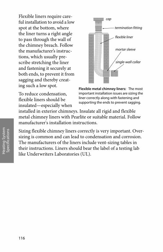
Hea
ting
Sys
tem
Sp
ecifi
cati
ons
116
Flexible liners require care-ful installation to avoid a low spot at the bottom, where the liner turns a right angle to pass through the wall of the chimney breach. Follow the manufacturer’s instruc-tions, which usually pre-scribe stretching the liner and fastening it securely at both ends, to prevent it from sagging and thereby creat-ing such a low spot.
To reduce condensation, flexible liners should be insulated—especially when installed in exterior chimneys. Insulate all rigid and flexible metal chimney liners with Pearlite or suitable material. Follow manufacturer's installation instructions.
Sizing flexible chimney liners correctly is very important. Over-sizing is common and can lead to condensation and corrosion. The manufacturers of the liners include vent-sizing tables in their instructions. Liners should bear the label of a testing lab like Underwriters Laboratories (UL).
Flexible metal chimney liners: The most important installation issues are sizing the liner correctly along with fastening and supporting the ends to prevent sagging.
cap
flexible liner
mortar sleeve
single-wall collar
termination fitting

Hea
ting
Sys
tem
Sp
ecifi
cati
ons
Weatherization Field Guide for Pennsylvania 117
Title.3.4 Special venting considerations for gas
The American Gas Associa-tion (AGA) has devised a clas-sification system for venting systems serving natural gas and propane appliances. This classification system assigns Roman numerals to four cate-gories of venting based on whether there is positive or negative pressure in the vent and whether condensation is likely to occur in the vent.
A great majority of appliances found in homes and multi-family buildings are Category I, which have negative pres-sure in vertical chimneys with no condensation expected in the vent connector or chimney. Condensing furnaces are usually Category IV with positive pressure in their vent and condensation occurring in both the appliance and vent.
Venting fan-assisted furnaces and boilers
Newer gas-fired fan-assisted heating appliances control flue-gas flow and excess air better than atmospheric heaters, resulting in higher efficiency. These are non-condensing Category I heating appliances in the 80%-plus Annual Fuel Utilization Efficiency (AFUE) range. Because these units eliminate dilution air and have slightly cooler flue gases, chimneys should be carefully inspected to ensure that they are suitable for a possibly more corrosive flue-gas flow. The chimney should be relined when any of the following three conditions are present.
AGA venting categories: The AGA classifies venting by whether there is positive or negative pressure in the vent and whether condensation is likely.
Negative-pressureVenting
Positive-pressureVenting
American Gas Association Vent Categories
Con
densing
Non
-con
densing I
II
III
IV
Combustion Efficiency Combustion Efficiency
Combustion Efficiency Combustion Efficiency
83% or less 83% or less
over 83% over 83%
Use standardventing: masonry or
Type B vent
Use onlypressurizable vent as
specified bymanufacturer
Use onlypressurizable
condensing-servicevent as specified by
manufacturer
Use only specialcondensing-servicevent as specified by
manufacturer
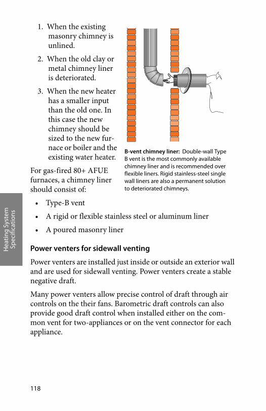
Hea
ting
Sys
tem
Sp
ecifi
cati
ons
118
1. When the existing masonry chimney is unlined.
2. When the old clay or metal chimney liner is deteriorated.
3. When the new heater has a smaller input than the old one. In this case the new chimney should be sized to the new fur-nace or boiler and the existing water heater.
For gas-fired 80+ AFUE furnaces, a chimney liner should consist of:
• Type-B vent
• A rigid or flexible stainless steel or aluminum liner
• A poured masonry liner
Power venters for sidewall venting
Power venters are installed just inside or outside an exterior wall and are used for sidewall venting. Power venters create a stable negative draft.
Many power venters allow precise control of draft through air controls on the their fans. Barometric draft controls can also provide good draft control when installed either on the com-mon vent for two-appliances or on the vent connector for each appliance.
B-vent chimney liner: Double-wall TypeB vent is the most commonly available chimney liner and is recommended over flexible liners. Rigid stainless-steel single-wall liners are also a permanent solution to deteriorated chimneys.

Hea
ting
Sys
tem
Sp
ecifi
cati
ons
Weatherization Field Guide for Pennsylvania 119
This more precise draft con-trol, provided by the power venter and/or barometric damper, minimizes excess combustion and dilution air. Flue gas temperatures for power venters can be cooler than temperatures needed to power vertical atmospheric chimneys. Less excess air and cooler flue gases can improve combustion efficiency in many cases. However, the power venter must be installed by a technician familiar with adjusting the draft to each appliance.
A single power venter can vent both a furnace or boiler and also a water heater. Types B or L vent are good choices for horizontal vent piping. Use Type B for gas only.
Power venters should be considered as a venting option when:
• Wind, internal house pressures, or nearby buildings have created a stubborn drafting problem that other options can’t solve.
• An existing horizontally vented appliance has weak draft and/or condensation problems.
• The cost of lining an unlined or deteriorated chimney exceeds the cost of installing a power venter with its hori-zontal vent.
• A floor furnace or other appliance with a long horizontal vent connector has backdrafting problems.
Power venters: Sidewall venting with a power venter is an excellent option when the chimney is dilapidated or when no chimney exists.
Hea
ting
Sys
tem
Sp
ecifi
cati
ons
120
Pressurized sidewall vents
Sometimes, the manufacturer gives the installer a venting choice of whether to install a fan-assisted furnace or boiler into a verti-cal chimney (Category I) or as a positive-draft appliance (Cate-gory III), vented through a sidewall vent. Sidewall-vented fan-assisted furnaces and boilers may vent through B-vent or stain-less-steel single-wall vent pipe. Pressurized sidewall vents must be airtight at the operating pressure. B-vent must be sealed with high-temperature silicone caulking or other approved means to air-seal its joints.
Some high-temperature positive-draft plastic vent pipe, used in horizontal installations, was recalled by manufacturers because of deterioration from heat and condensation. Deteriorated high-temperature plastic vent must be replaced by airtight stainless-steel vent piping or B-vent.
Existing fan-assisted appliances may have problems with weak draft and condensation when vented horizontally. Horizontally vented, fan-assisted furnaces and boilers may require a power venter to create adequate draft.
Table Title-9:Characteristics of Gas Furnaces and Boilers
AFUE Operating characteristics
70+Category I, draft diverter, no draft fan, standing pilot, non-condensing, indoor combustion and dilution air
80+Category I, no draft diverter, draft fan, electronic ignition, indoor combustion air
90+
Category IV, no draft diverter, draft fan, low-tem-perature plastic venting, positive draft, electronic ignition, condensing heat exchanger, outdoor combustion air is to be provided
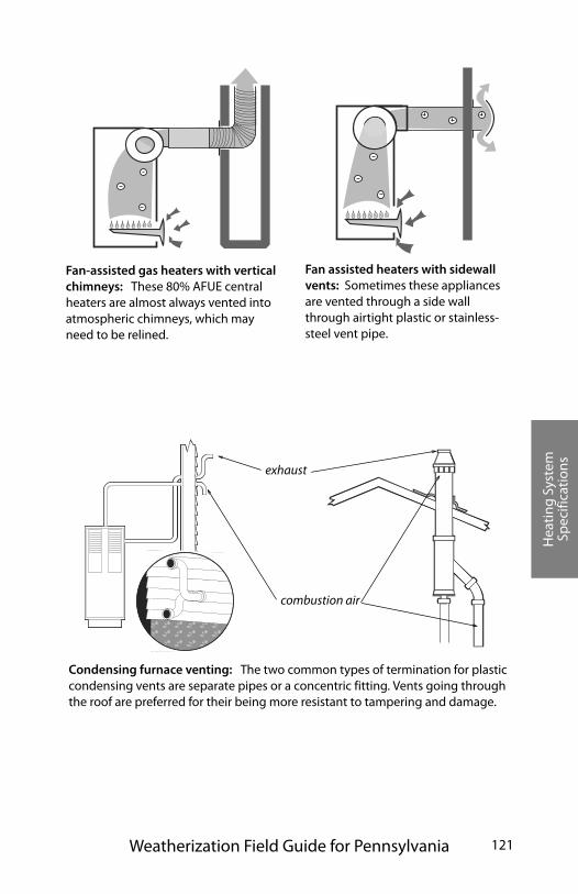
Hea
ting
Sys
tem
Sp
ecifi
cati
ons
Weatherization Field Guide for Pennsylvania 121
Fan-assisted gas heaters with vertical chimneys: These 80% AFUE central heaters are almost always vented into atmospheric chimneys, which may need to be relined.
Fan assisted heaters with sidewall vents: Sometimes these appliances are vented through a side wall through airtight plastic or stainless-steel vent pipe.
exhaust
combustion air
Condensing furnace venting: The two common types of termination for plastic condensing vents are separate pipes or a concentric fitting. Vents going through the roof are preferred for their being more resistant to tampering and damage.
Hea
ting
Sys
tem
Sp
ecifi
cati
ons
122
Condensing-furnace venting
Condensing furnaces with 90+ AFUE are vented horizontally or vertically through non-cellular PVC Schedule 40 pipe. The vent is pressurized, making it Category IV. Vent piping should be sloped back toward the appliance, so the condensate can be drained and treated if necessary.
Combustion air is supplied from outdoors through a sealed plastic pipe or from indoors. Outdoor combustion air is required, and most condensing furnaces are equipped for out-door combustion air through a dedicated inlet pipe. This com-bined combustion-air and venting system is referred to as direct-vent or sealed-combustion.
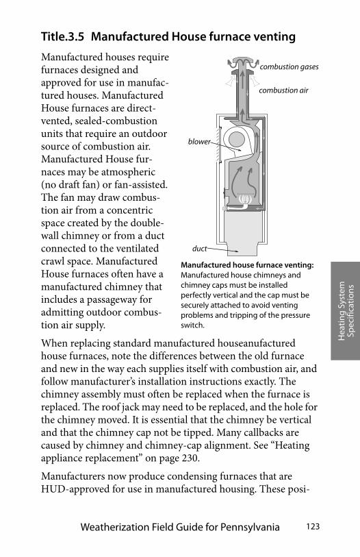
Hea
ting
Sys
tem
Sp
ecifi
cati
ons
Weatherization Field Guide for Pennsylvania 123
Title.3.5 Manufactured House furnace venting
Manufactured houses require furnaces designed and approved for use in manufac-tured houses. Manufactured House furnaces are direct-vented, sealed-combustion units that require an outdoor source of combustion air. Manufactured House fur-naces may be atmospheric (no draft fan) or fan-assisted. The fan may draw combus-tion air from a concentric space created by the double-wall chimney or from a duct connected to the ventilated crawl space. Manufactured House furnaces often have a manufactured chimney that includes a passageway for admitting outdoor combus-tion air supply.
When replacing standard manufactured houseanufactured house furnaces, note the differences between the old furnace and new in the way each supplies itself with combustion air, and follow manufacturer’s installation instructions exactly. The chimney assembly must often be replaced when the furnace is replaced. The roof jack may need to be replaced, and the hole for the chimney moved. It is essential that the chimney be vertical and that the chimney cap not be tipped. Many callbacks are caused by chimney and chimney-cap alignment. See “Heating appliance replacement” on page 230.
Manufacturers now produce condensing furnaces that are HUD-approved for use in manufactured housing. These posi-
Manufactured house furnace venting: Manufactured house chimneys and chimney caps must be installed perfectly vertical and the cap must be securely attached to avoid venting problems and tripping of the pressure switch.
combustion air
blower
duct
combustion gases
Hea
ting
Sys
tem
Sp
ecifi
cati
ons
124
tive-draft furnaces may eliminate venting and combustion-air problems, common to manufactured house furnaces, because of their robust positive draft and negatively pressurized combus-tion-air vent.
Title.3.6 Wood-heating venting and safety
Wood heating is a popular and effective auxiliary heating source for homes. However, wood stoves and fireplaces can cause indoor-air-pollution and fire hazards. As part of health and safety work, it’s important to inspect wood stoves to assess potential hazards.
Stoves that are listed by a testing agency like Underwriters Labo-ratory have a tag stating their clearance from combustibles. Unlisted stoves should conform to the minimum clearances shown here. Ventilated wall protectors, described in NFPA codes and standards, generally allow the listed clearance to be reduced by half. See “Venting combustion gases” on page 109.
All components of wood-stove venting systems should be approved for use with wood stoves. Chimney sections penetrat-ing floor, ceiling, or roof should have approved thimbles, sup-port packages, and ventilated shields to protect combustible materials from high temperatures.
Inspect stove, vent connector, and chimney for correct clearances from combustible materials as listed in NFPA 211. Ensure that stove is sitting on a noncombustible floor.
Inspect vent connector and chimney for leaks, and seal leaks with a high-temperature sealant designed for use with metal or masonry.
Inspect chimney and vent connector for creosote build-up, and clean chimney if creosote build-up exists.
Inspect the house for soot on seldom-cleaned horizontal surfaces. If soot is present or if the blower door indicates leakage, inspect and replace the gasket on the wood-stove door if appropriate. Seal other air leaks, and take steps to

Hea
ting
Sys
tem
Sp
ecifi
cati
ons
Weatherization Field Guide for Pennsylvania 125
improve draft as necessary, to reduce indoor smoke emis-sions.
Inspect and clean stack damper and/or combustion air intake if necessary.
Check catalytic combustor for repair or replacement if the wood stove has one.
Assure that heat exchanger surfaces and flue passages within the wood stove are free of accumulations of soot or debris.
support package
to ventilated wall protector
single-wall
double-wall
clearance to combustibles; as per manufacturer's instructions and prevailing code
Wood-stove installation: Wood-stove venting and clearances are vitally important to wood-burning safety. Read and follow all manufacturer’s instructions for the stove and its venting components.
18"
18"
36"
insulation shield
Note: Newer wood stoves have a metal tag stating their required clearance from combustibles, which may be less than 18 inches.
vent connector
1 pipe diameter
to combustibles
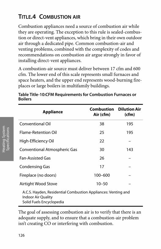
Hea
ting
Sys
tem
Sp
ecifi
cati
ons
126
TITLE.4 COMBUSTION AIR
Combustion appliances need a source of combustion air while they are operating. The exception to this rule is sealed-combus-tion or direct-vent appliances, which bring in their own outdoor air through a dedicated pipe. Common combustion-air and venting problems, combined with the complexity of codes and recommendations on combustion air argue strongly in favor of installing direct-vent appliances.
A combustion-air source must deliver between 17 cfm and 600 cfm. The lower end of this scale represents small furnaces and space heaters, and the upper end represents wood-burning fire-places or large boilers in multifamily buildings.
The goal of assessing combustion air is to verify that there is an adequate supply, and to ensure that a combustion-air problem isn’t creating CO or interfering with combustion.
Table Title-10:CFM Requirements for Combustion Furnaces or Boilers
ApplianceCombustion
Air (cfm)Dilution Air
(cfm)
Conventional Oil 38 195
Flame-Retention Oil 25 195
High-Efficiency Oil 22 –
Conventional Atmospheric Gas 30 143
Fan-Assisted Gas 26 –
Condensing Gas 17 –
Fireplace (no doors) 100–600 –
Airtight Wood Stove 10–50 –
A.C.S. Hayden, Residential Combustion Appliances: Venting and Indoor Air QualitySolid Fuels Encyclopedia
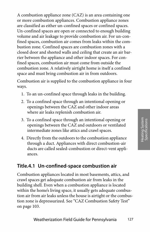
Hea
ting
Sys
tem
Sp
ecifi
cati
ons
Weatherization Field Guide for Pennsylvania 127
A combustion appliance zone (CAZ) is an area containing one or more combustion appliances. Combustion appliance zones are classified as either un-confined spaces or confined spaces. Un-confined spaces are open or connected to enough building volume and air leakage to provide combustion air. For un-con-fined spaces, combustion air comes from leaks within the com-bustion zone. Confined spaces are combustion zones with a closed door and sheeted walls and ceiling that create an air bar-rier between the appliance and other indoor spaces. For con-fined spaces, combustion air must come from outside the combustion zone. A relatively airtight home is itself a confined space and must bring combustion air in from outdoors.
Combustion air is supplied to the combustion appliance in four ways.
1. To an un-confined space through leaks in the building.
2. To a confined space through an intentional opening or openings between the CAZ and other indoor areas where air leaks replenish combustion air.
3. To a confined space through an intentional opening or openings between the CAZ and outdoors or ventilated intermediate zones like attics and crawl spaces.
4. Directly from the outdoors to the combustion appliance through a duct. Appliances with direct combustion-air ducts are called sealed-combustion or direct-vent appli-ances.
Title.4.1 Un-confined-space combustion air
Combustion appliances located in most basements, attics, and crawl spaces get adequate combustion air from leaks in the building shell. Even when a combustion appliance is located within the home’s living space, it usually gets adequate combus-tion air from air leaks unless the house is airtight or the combus-tion zone is depressurized. See “CAZ Combustion Safety Test” on page 103.
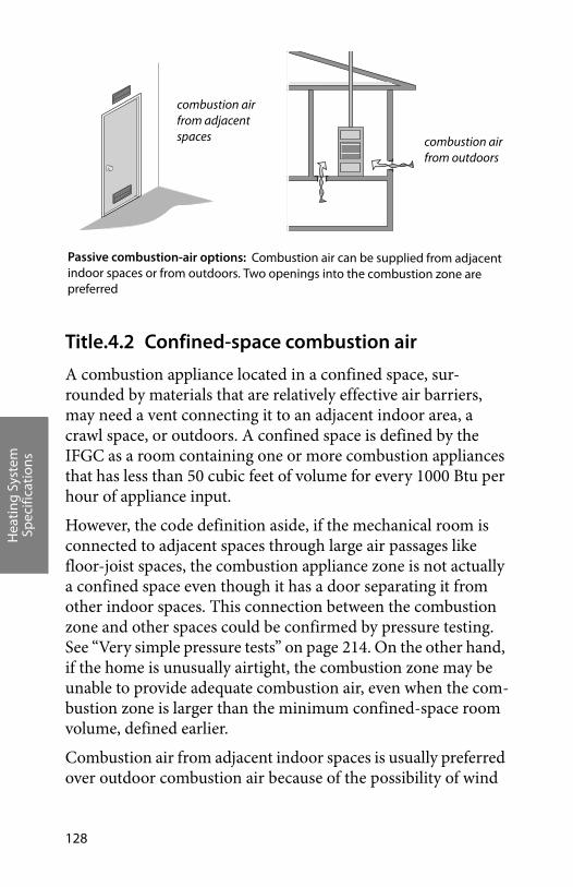
Hea
ting
Sys
tem
Sp
ecifi
cati
ons
128
Title.4.2 Confined-space combustion air
A combustion appliance located in a confined space, sur-rounded by materials that are relatively effective air barriers, may need a vent connecting it to an adjacent indoor area, a crawl space, or outdoors. A confined space is defined by the IFGC as a room containing one or more combustion appliances that has less than 50 cubic feet of volume for every 1000 Btu per hour of appliance input.
However, the code definition aside, if the mechanical room is connected to adjacent spaces through large air passages like floor-joist spaces, the combustion appliance zone is not actually a confined space even though it has a door separating it from other indoor spaces. This connection between the combustion zone and other spaces could be confirmed by pressure testing. See “Very simple pressure tests” on page 214. On the other hand, if the home is unusually airtight, the combustion zone may be unable to provide adequate combustion air, even when the com-bustion zone is larger than the minimum confined-space room volume, defined earlier.
Combustion air from adjacent indoor spaces is usually preferred over outdoor combustion air because of the possibility of wind
combustion air from adjacent spaces combustion air
from outdoors
Passive combustion-air options: Combustion air can be supplied from adjacent indoor spaces or from outdoors. Two openings into the combustion zone are preferred
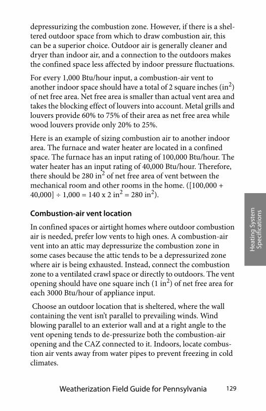
Hea
ting
Sys
tem
Sp
ecifi
cati
ons
Weatherization Field Guide for Pennsylvania 129
depressurizing the combustion zone. However, if there is a shel-tered outdoor space from which to draw combustion air, this can be a superior choice. Outdoor air is generally cleaner and dryer than indoor air, and a connection to the outdoors makes the confined space less affected by indoor pressure fluctuations.
For every 1,000 Btu/hour input, a combustion-air vent to another indoor space should have a total of 2 square inches (in2) of net free area. Net free area is smaller than actual vent area and takes the blocking effect of louvers into account. Metal grills and louvers provide 60% to 75% of their area as net free area while wood louvers provide only 20% to 25%.
Here is an example of sizing combustion air to another indoor area. The furnace and water heater are located in a confined space. The furnace has an input rating of 100,000 Btu/hour. The water heater has an input rating of 40,000 Btu/hour. Therefore, there should be 280 in2 of net free area of vent between the mechanical room and other rooms in the home. ([100,000 + 40,000] ÷ 1,000 = 140 x 2 in2 = 280 in2).
Combustion-air vent location
In confined spaces or airtight homes where outdoor combustion air is needed, prefer low vents to high ones. A combustion-air vent into an attic may depressurize the combustion zone in some cases because the attic tends to be a depressurized zone where air is being exhausted. Instead, connect the combustion zone to a ventilated crawl space or directly to outdoors. The vent opening should have one square inch (1 in2) of net free area for each 3000 Btu/hour of appliance input.
Choose an outdoor location that is sheltered, where the wall containing the vent isn’t parallel to prevailing winds. Wind blowing parallel to an exterior wall and at a right angle to the vent opening tends to de-pressurize both the combustion-air opening and the CAZ connected to it. Indoors, locate combus-tion air vents away from water pipes to prevent freezing in cold climates.
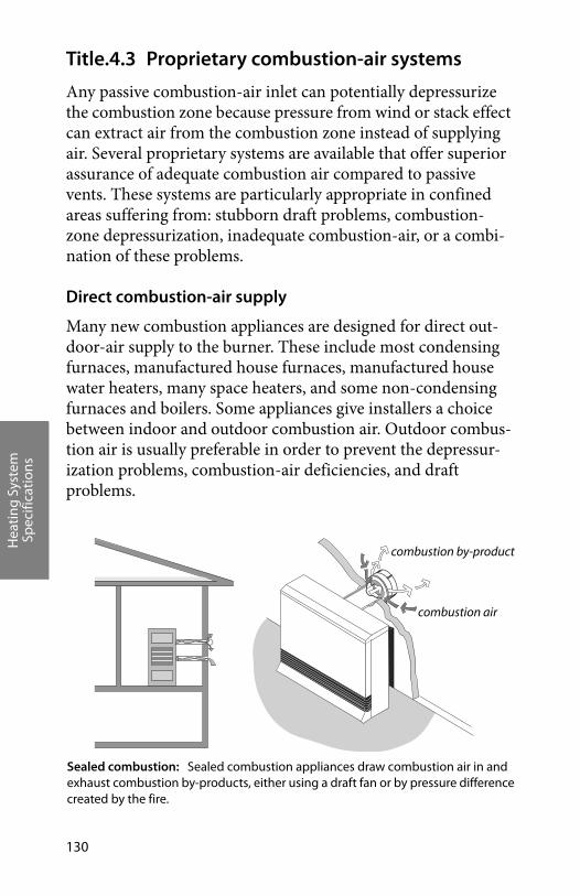
Hea
ting
Sys
tem
Sp
ecifi
cati
ons
130
Title.4.3 Proprietary combustion-air systems
Any passive combustion-air inlet can potentially depressurize the combustion zone because pressure from wind or stack effect can extract air from the combustion zone instead of supplying air. Several proprietary systems are available that offer superior assurance of adequate combustion air compared to passive vents. These systems are particularly appropriate in confined areas suffering from: stubborn draft problems, combustion-zone depressurization, inadequate combustion-air, or a combi-nation of these problems.
Direct combustion-air supply
Many new combustion appliances are designed for direct out-door-air supply to the burner. These include most condensing furnaces, manufactured house furnaces, manufactured house water heaters, many space heaters, and some non-condensing furnaces and boilers. Some appliances give installers a choice between indoor and outdoor combustion air. Outdoor combus-tion air is usually preferable in order to prevent the depressur-ization problems, combustion-air deficiencies, and draft problems.
combustion air
combustion by-products
Sealed combustion: Sealed combustion appliances draw combustion air in and exhaust combustion by-products, either using a draft fan or by pressure differencecreated by the fire.
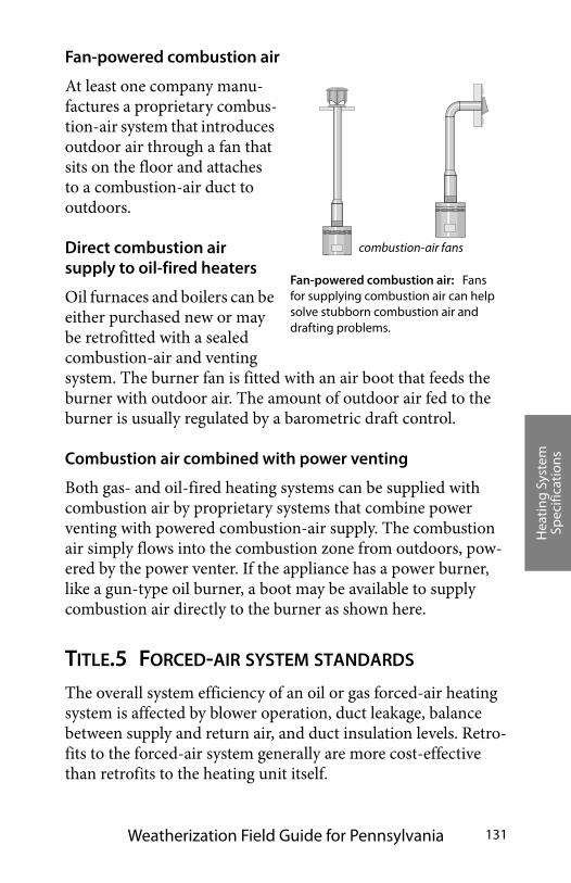
Hea
ting
Sys
tem
Sp
ecifi
cati
ons
Weatherization Field Guide for Pennsylvania 131
Fan-powered combustion air
At least one company manu-factures a proprietary combus-tion-air system that introduces outdoor air through a fan that sits on the floor and attaches to a combustion-air duct to outdoors.
Direct combustion air supply to oil-fired heaters
Oil furnaces and boilers can be either purchased new or may be retrofitted with a sealed combustion-air and venting system. The burner fan is fitted with an air boot that feeds the burner with outdoor air. The amount of outdoor air fed to the burner is usually regulated by a barometric draft control.
Combustion air combined with power venting
Both gas- and oil-fired heating systems can be supplied with combustion air by proprietary systems that combine power venting with powered combustion-air supply. The combustion air simply flows into the combustion zone from outdoors, pow-ered by the power venter. If the appliance has a power burner, like a gun-type oil burner, a boot may be available to supply combustion air directly to the burner as shown here.
TITLE.5 FORCED-AIR SYSTEM STANDARDS
The overall system efficiency of an oil or gas forced-air heating system is affected by blower operation, duct leakage, balance between supply and return air, and duct insulation levels. Retro-fits to the forced-air system generally are more cost-effective than retrofits to the heating unit itself.
Fan-powered combustion air: Fans for supplying combustion air can help solve stubborn combustion air and drafting problems.
combustion-air fans
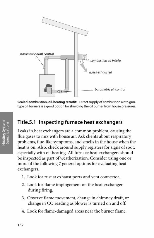
Hea
ting
Sys
tem
Sp
ecifi
cati
ons
132
Title.5.1 Inspecting furnace heat exchangers
Leaks in heat exchangers are a common problem, causing the flue gases to mix with house air. Ask clients about respiratory problems, flue-like symptoms, and smells in the house when the heat is on. Also, check around supply registers for signs of soot, especially with oil heating. All furnace heat exchangers should be inspected as part of weatherization. Consider using one or more of the following 7 general options for evaluating heat exchangers.
1. Look for rust at exhaust ports and vent connector.
2. Look for flame impingement on the heat exchanger during firing.
3. Observe flame movement, change in chimney draft, or change in CO reading as blower is turned on and off.
4. Look for flame-damaged areas near the burner flame.
Sealed-combustion, oil-heating retrofit: Direct supply of combustion air to gun-type oil burners is a good option for shielding the oil burner from house pressures.
barometric draft control
barometric air control
gases exhausted
combustion air intake
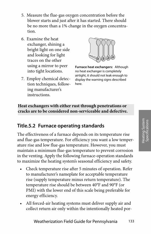
Hea
ting
Sys
tem
Sp
ecifi
cati
ons
Weatherization Field Guide for Pennsylvania 133
5. Measure the flue-gas oxygen concentration before the blower starts and just after it has started. There should be no more than a 1% change in the oxygen concentra-tion.
6. Examine the heat exchanger, shining a bright light on one side and looking for light traces on the other using a mirror to peer into tight locations.
7. Employ chemical detec-tion techniques, follow-ing manufacturer’s instructions.
Title.5.2 Furnace operating standards
The effectiveness of a furnace depends on its temperature rise and flue-gas temperature. For efficiency you want a low temper-ature rise and low flue-gas temperature. However, you must maintain a minimum flue-gas temperature to prevent corrosion in the venting. Apply the following furnace-operation standards to maximize the heating system’s seasonal efficiency and safety.
• Check temperature rise after 5 minutes of operation. Refer to manufacturer’s nameplate for acceptable temperature rise (supply temperature minus return temperature). The temperature rise should be between 40°F and 90°F (or PMI) with the lower end of this scale being preferable for energy efficiency.
• All forced-air heating systems must deliver supply air and collect return air only within the intentionally heated por-
Furnace heat exchangers: Although no heat exchanger is completely airtight, it should not leak enough to display the warning signs described here.
Heat exchangers with either rust through penetrations or cracks are to be considered non-serviceable and defective.
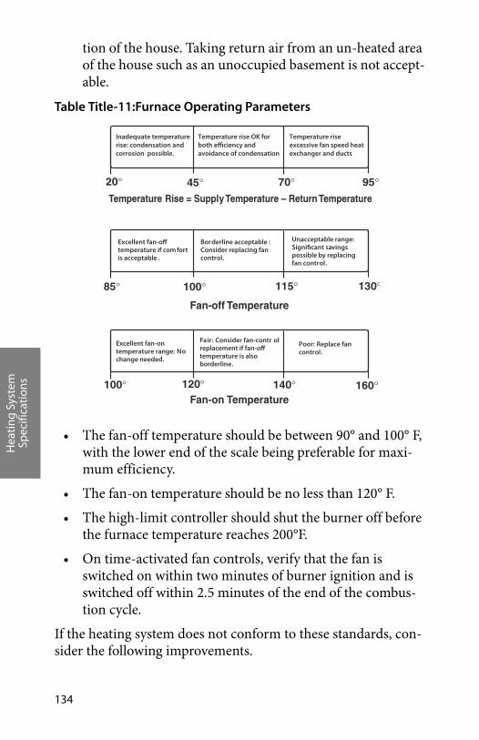
Hea
ting
Sys
tem
Sp
ecifi
cati
ons
134
tion of the house. Taking return air from an un-heated area of the house such as an unoccupied basement is not accept-able.
• The fan-off temperature should be between 90° and 100° F, with the lower end of the scale being preferable for maxi-mum efficiency.
• The fan-on temperature should be no less than 120° F.
• The high-limit controller should shut the burner off before the furnace temperature reaches 200°F.
• On time-activated fan controls, verify that the fan is switched on within two minutes of burner ignition and is switched off within 2.5 minutes of the end of the combus-tion cycle.
If the heating system does not conform to these standards, con-sider the following improvements.
Table Title-11:Furnace Operating Parameters
Inadequate temperaturerise: condensation and corrosion possible.
Temperature riseexcessive fan speed heatexchanger and ducts
Excellent fan-offtemperature if com fortis acceptable .
Borderline acceptable :Consider replacing fancontrol.
Unacceptable range:Significant savingspossible by replacingfan control.
Excellent fan-ontemperature range: Nochange needed.
Fair: Consider fan-contr olreplacement if fan-offtemperature is alsoborderline.
Poor: Replace fancontrol.
20� 45� 70� 95�
85� 100� 115� 130�
100� 120� 140� 160�
Rise = Supply Temperature – Return Temperature
Fan-off Temperature
Temperature
Temperature rise OK forboth efficiency and avoidance of condensation
Fan-on Temperature
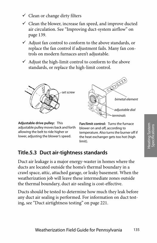
Hea
ting
Sys
tem
Sp
ecifi
cati
ons
Weatherization Field Guide for Pennsylvania 135
Clean or change dirty filters
Clean the blower, increase fan speed, and improve ducted air circulation. See “Improving duct-system airflow” on page 139.
Adjust fan control to conform to the above standards, or replace the fan control if adjustment fails. Many fan con-trols on modern furnaces aren’t adjustable.
Adjust the high-limit control to conform to the above standards, or replace the high-limit control.
Title.5.3 Duct air-tightness standards
Duct air leakage is a major energy-waster in homes where the ducts are located outside the home’s thermal boundary in a crawl space, attic, attached garage, or leaky basement. When the weatherization job will leave these intermediate zones outside the thermal boundary, duct air-sealing is cost-effective.
Ducts should be tested to determine how much they leak before any duct air sealing is performed. For information on duct test-ing, see “Duct airtightness testing” on page 221.
Adjustable drive pulley: This adjustable pulley moves back and forth allowing the belt to ride higher or lower, adjusting the blower’s speed.
set screw
terminals
bimetal element
adjustable dial
Fan/limit control: Turns the furnace blower on and off, according to temperature. Also turns the burner off if the heat exchanger gets too hot (high limit).
Hea
ting
Sys
tem
Sp
ecifi
cati
ons
136
Duct leakage sites
Ducts located outside the thermal boundary or in an intermedi-ate zone like a ventilated attic or crawl space should be sealed. The following is a list of duct-leak locations in order of their rel-ative importance. Leaks nearer to the air handler see higher pressure and are more important than leaks further away.
First, seal all return leaks within the combustion zone to prevent this leakage from depressurizing the combustion zone and causing backdrafting.
Plenum joint at air handler: These joints may have been difficult to fasten and seal because of tight access. Go the extra mile to seal them airtight by caulking this important joint even if it requires cutting an access hole in the ple-num. (Avoid mastic and fabric mesh here for future access—furnace replacement, for example.)
Joints at branch takeoffs: These important joints should be sealed with a thick layer of mastic. Fabric mesh tape is a plus for new installations or when access is easy.
Joints in sectioned elbows: Known as gores, these are usu-ally leaky.
Tabbed sleeves: Attach the sleeve to the main duct with 3-to-5 screws and apply mastic plentifully.
Flexduct-to-metal joints: Apply mastic to the metal sleeve. Clamp the flexduct’s inner liner over this strip of mastic with a plastic strap, using a strap tensioner. Clamp the insulation and outer liner with another strap.
Support ducts and duct joints with duct hangers where needed.
Seal leaky joints between building materials composing cavity-return ducts, like panned floor cavities and furnace return platforms.

Hea
ting
Sys
tem
Sp
ecifi
cati
ons
Weatherization Field Guide for Pennsylvania 137
Seal leaky joints between supply and return registers and the floor, wall, and ceil-ing to which they are attached.
Consider sealing off supply and return registers in unoccupied basements.
Seal penetrations made by wires or pipes traveling through ducts. Even better: move the pipes and wires and patch the holes.
Flexduct joints: Flexduct itself is usually fairly airtight, but joints, sealed improperly with tape, can be very leaky. Use methods shown here to make flexduct joints airtight.
strap tightener
sheet-metal screw
metal sleeve
inner linerinsulationtightened straps
tabbed sleeve
Panned floor joists: These return ducts are often very leaky and may require removing the panning to seal the cavity.
return register
return duct
leakage
leakage
metal panning

Hea
ting
Sys
tem
Sp
ecifi
cati
ons
138
Materials for duct air-sealing
Duct mastic is the preferred duct-sealing material because of its supe-rior durability and adhesion. Apply at least 1/16-inch thick and use rein-forcing mesh for all joints wider than 1/8 inch or joints that may experience some movement.
Siliconized acrylic-latex caulk is acceptable for sealing joints in panned joist spaces, used for return ducts.
Joints should rely on mechanical fasteners to prevent joint movement or separation. Tape should never be expected to hold a joint together nor expected to resist the force of compacted insulation or joint movement. Aluminum foil or cloth duct tape are not good materials for duct sealing because their adhesive often fails after a short time.
Title.5.4 Duct insulation
Insulate supply ducts that run through unconditioned areas out-side the thermal boundary such as crawl spaces, attics, and attached garages with a minimum of R-11 vinyl- or foil-faced duct insulation. Don’t insulate ducts that run through condi-tioned areas unless they cause overheating in winter or conden-sation in summer. Follow the best practices listed below for installing insulation.
• Always perform necessary duct sealing before insulating ducts.
• Insulation should cover all exposed supply ducts, without significant areas of bare duct left uninsulated.
�� � � � � � �� ��
Duct mastic: Mastic, reinforced with fabric webbing, is the best choice for sealing ducts.
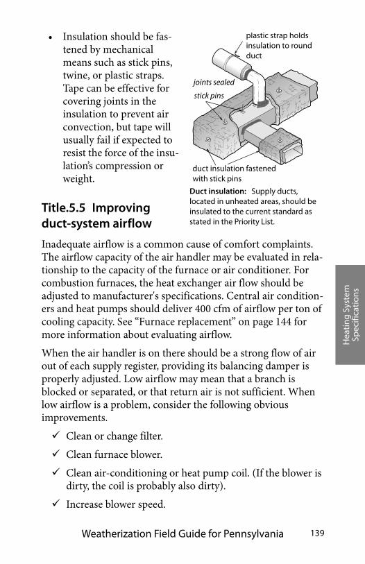
Hea
ting
Sys
tem
Sp
ecifi
cati
ons
Weatherization Field Guide for Pennsylvania 139
• Insulation should be fas-tened by mechanical means such as stick pins, twine, or plastic straps. Tape can be effective for covering joints in the insulation to prevent air convection, but tape will usually fail if expected to resist the force of the insu-lation’s compression or weight.
Title.5.5 Improving duct-system airflow
Inadequate airflow is a common cause of comfort complaints. The airflow capacity of the air handler may be evaluated in rela-tionship to the capacity of the furnace or air conditioner. For combustion furnaces, the heat exchanger air flow should be adjusted to manufacturer's specifications. Central air condition-ers and heat pumps should deliver 400 cfm of airflow per ton of cooling capacity. See “Furnace replacement” on page 144 for more information about evaluating airflow.
When the air handler is on there should be a strong flow of air out of each supply register, providing its balancing damper is properly adjusted. Low airflow may mean that a branch is blocked or separated, or that return air is not sufficient. When low airflow is a problem, consider the following obvious improvements.
Clean or change filter.
Clean furnace blower.
Clean air-conditioning or heat pump coil. (If the blower is dirty, the coil is probably also dirty).
Increase blower speed.
joints sealed
plastic strap holds insulation to round duct
duct insulation fastened with stick pins
stick pins
Duct insulation: Supply ducts, located in unheated areas, should be insulated to the current standard as stated in the Priority List.
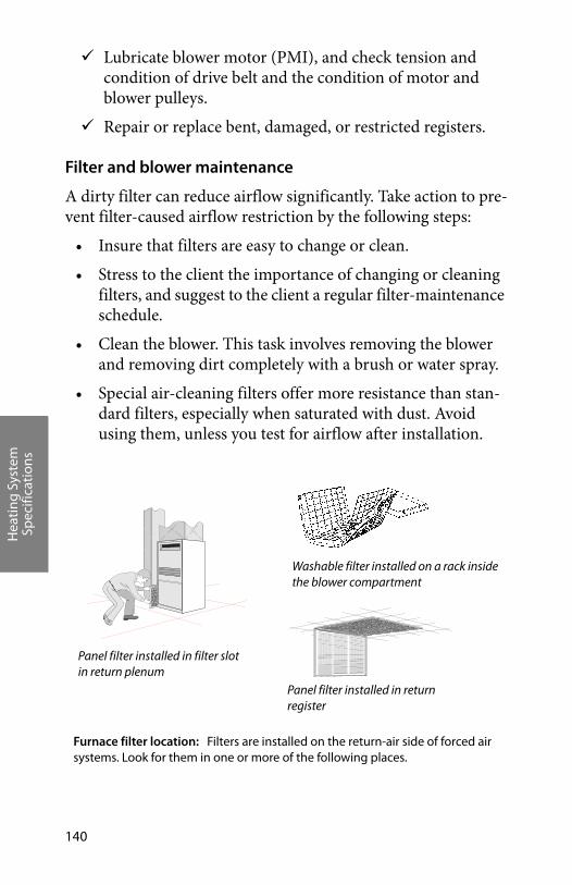
Hea
ting
Sys
tem
Sp
ecifi
cati
ons
140
Lubricate blower motor (PMI), and check tension and condition of drive belt and the condition of motor and blower pulleys.
Repair or replace bent, damaged, or restricted registers.
Filter and blower maintenance
A dirty filter can reduce airflow significantly. Take action to pre-vent filter-caused airflow restriction by the following steps:
• Insure that filters are easy to change or clean.
• Stress to the client the importance of changing or cleaning filters, and suggest to the client a regular filter-maintenance schedule.
• Clean the blower. This task involves removing the blower and removing dirt completely with a brush or water spray.
• Special air-cleaning filters offer more resistance than stan-dard filters, especially when saturated with dust. Avoid using them, unless you test for airflow after installation.
Washable filter installed on a rack inside the blower compartment
Panel filter installed in return register
Panel filter installed in filter slot in return plenum
Furnace filter location: Filters are installed on the return-air side of forced air systems. Look for them in one or more of the following places.
Hea
ting
Sys
tem
Sp
ecifi
cati
ons
Weatherization Field Guide for Pennsylvania 141
Duct improvements to increase airflow and improve comfort
Consider the following improvements in response to customer complaints and conditions you observe during a thorough duct inspection. Unbalanced airflow through ducts can pressurize or depressurize rooms, leading to increased air leakage through the building shell. For information on how to test these room pres-sures, see “Measuring duct-induced pressures” on page 223. Consider the following duct changes to increase system airflow and reduce the imbalance between supply and return.
• Remove obstructions to registers and ducts such as rugs, furniture, and objects placed inside ducts, like children’s toys and water pans for humidification.
• Remove kinks from flex duct, and replace collapsed flex duct and fiberglass duct board.
• Install additional supply ducts and return ducts as needed to provide conditioned air throughout the building, espe-cially into additions to the building.
• Undercut bedroom doors, especially in homes with single return registers.
• Install a transfer grille between the bedroom and main body of house to improve airflow.
• Retrofit jumper ducts, composed of one register in the bed-room, one register in the central return-air zone, and a duct in between (usually running through an attic or crawl space).
• Install registers and grilles where missing.

Hea
ting
Sys
tem
Sp
ecifi
cati
ons
142
New ducts
New ducts should not be installed in unconditioned spaces unless absolutely necessary. If ducts are located in uncondi-tioned spaces, joints should be sealed and the ducts insulated as described previously. See “Duct air-tightness standards” on page 135 and “Duct insulation” on page 138.
New ducts must be physically connected to the existing distri-bution system or to the furnace. Install balancing damper in each new branch duct. Registers should terminate each new supply or return branch duct.
TITLE.6 HEATING-SYSTEM REPLACEMENT SPECIFICATIONS
All heating replacement systems must have dedicated combus-tion air whenever possible. Don’t assume that older furnaces and boilers are inefficient until testing them. During testing, make appropriate efforts to repair and adjust the existing fur-
Restricted return air: Return air is often restricted, requiring a variety of strategies to relieve the resulting house pressures and low system airflow. Installing an additional return duct directly into the air handler is a preferred strategy.
Installing grills in doors or through walls allows return air to escape from bedrooms
Jumper ducts can bring air from a restricted area of the home back to a main return register.

Hea
ting
Sys
tem
Sp
ecifi
cati
ons
Weatherization Field Guide for Pennsylvania 143
nace or boiler, before deciding to replace it. Replacement parts like gas valves and controls for older heating units are com-monly available.
Heating appliances are often replaced when the cost of repairs and retrofits exceeds one half of estimated replace-ment costs. Estimate the repair and retrofit costs and com-pare them to replacement cost before deciding between retro-fit and replacement.
Replacements should only be considered if repairs are impractical or expensive or if a replacement shows a savings to investment ratio (SIR) of 1.0 or better as modeled by NEAT. Replacement should be con-sidered if existing furnace falls outside of the PA parameters for health, safety and efficiency.”
New heating appliances must be installed to manufacturer’s specifications or current code requirements, whichever is more stringent, and follow all applicable building and fire codes. Replacement gas heating appliances should have a minimum Annual Fuel Utilization Efficiency (AFUE) of 90% and be installed as a two-pipe direct-vent or concentric flue system for exhaust and combustion air. Combustion air must be derived from outdoors. These high-efficiency furnaces are direct-vent, sealed-combustion units with health and safety benefits in addi-tion to their superior efficiency and significantly lower fuel usage. Boilers and oil-fired units must have a minimum AFUE of 82%.
Heat load calculations, used to size the new heater, should account for reduced heating loads, resulting from insulation and
Oil-fired downflow furnaces: Their design hasn’t changed much in recent years except for the flame-retention burner.
burner
heat exchanger
blower
primary control
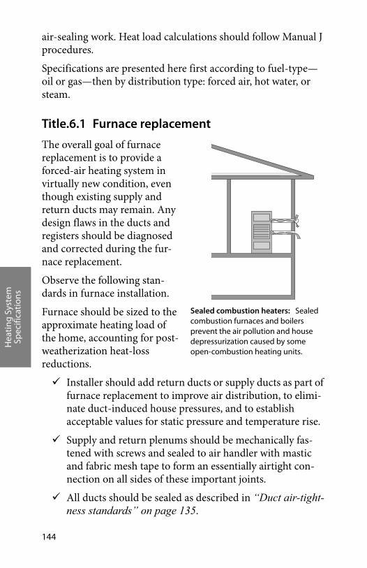
Hea
ting
Sys
tem
Sp
ecifi
cati
ons
144
air-sealing work. Heat load calculations should follow Manual J procedures.
Specifications are presented here first according to fuel-type—oil or gas—then by distribution type: forced air, hot water, or steam.
Title.6.1 Furnace replacement
The overall goal of furnace replacement is to provide a forced-air heating system in virtually new condition, even though existing supply and return ducts may remain. Any design flaws in the ducts and registers should be diagnosed and corrected during the fur-nace replacement.
Observe the following stan-dards in furnace installation.
Furnace should be sized to the approximate heating load of the home, accounting for post-weatherization heat-loss reductions.
Installer should add return ducts or supply ducts as part of furnace replacement to improve air distribution, to elimi-nate duct-induced house pressures, and to establish acceptable values for static pressure and temperature rise.
Supply and return plenums should be mechanically fas-tened with screws and sealed to air handler with mastic and fabric mesh tape to form an essentially airtight con-nection on all sides of these important joints.
All ducts should be sealed as described in “Duct air-tight-ness standards” on page 135.
Sealed combustion heaters: Sealed combustion furnaces and boilers prevent the air pollution and house depressurization caused by some open-combustion heating units.
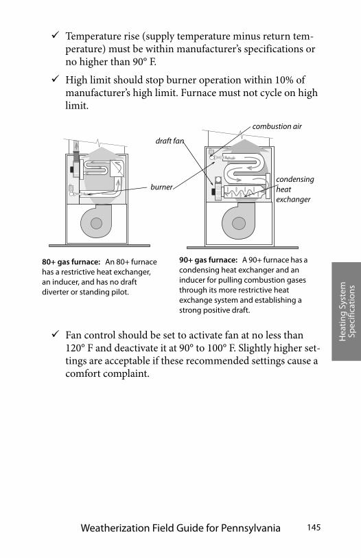
Hea
ting
Sys
tem
Sp
ecifi
cati
ons
Weatherization Field Guide for Pennsylvania 145
Temperature rise (supply temperature minus return tem-perature) must be within manufacturer’s specifications or no higher than 90° F.
High limit should stop burner operation within 10% of manufacturer’s high limit. Furnace must not cycle on high limit.
Fan control should be set to activate fan at no less than 120° F and deactivate it at 90° to 100° F. Slightly higher set-tings are acceptable if these recommended settings cause a comfort complaint.
80+ gas furnace: An 80+ furnace has a restrictive heat exchanger, an inducer, and has no draft diverter or standing pilot.
condensing heat exchanger
burner
draft fan
combustion air
90+ gas furnace: A 90+ furnace has a condensing heat exchanger and an inducer for pulling combustion gases through its more restrictive heat exchange system and establishing a strong positive draft.

Hea
ting
Sys
tem
Sp
ecifi
cati
ons
146
Static pressure, mea-sured in both supply and return plenums should be within manufac-turer’s specifications.
Blower should not be set to operate continuously.
Seal holes through the jacket of the air handler with mastic or foil tape.
Filters should be held firmly in place and pro-vide complete coverage of blower intake or return register. Filters should be easy to replace.
Title.6.2 Oil-fired heating installation
The overall goal of the system replacement is to provide an oil-fired heating system in virtually new condition, even though components like the oil tank, chimney, piping, or ducts may remain. Any maintenance or repair on these remaining compo-nents should be considered part of the job. Any design flaws related to the original system should be diagnosed and corrected during the heating-system replacement.
Examine existing chimney and vent connector for suitabil-ity as venting for new appliance. The vent connector may need to be re-sized and the chimney may need to be re-lined.
Check clearances of heating unit and its vent connector to nearby combustibles, by referring to NFPA 31.
Static pressure and temperature rise: Testing static pressure and temperature rise across the new furnace should verify that the duct system isn’t restricted. The temperature rise is specified by the manufacturer on the name plate of the Furnace.
55
T
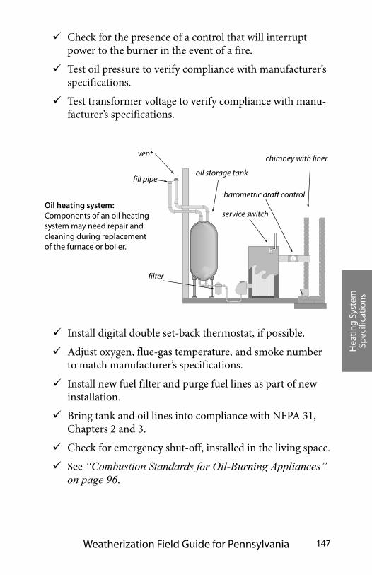
Hea
ting
Sys
tem
Sp
ecifi
cati
ons
Weatherization Field Guide for Pennsylvania 147
Check for the presence of a control that will interrupt power to the burner in the event of a fire.
Test oil pressure to verify compliance with manufacturer’s specifications.
Test transformer voltage to verify compliance with manu-facturer’s specifications.
Install digital double set-back thermostat, if possible.
Adjust oxygen, flue-gas temperature, and smoke number to match manufacturer’s specifications.
Install new fuel filter and purge fuel lines as part of new installation.
Bring tank and oil lines into compliance with NFPA 31, Chapters 2 and 3.
Check for emergency shut-off, installed in the living space.
See “Combustion Standards for Oil-Burning Appliances” on page 96.
Oil heating system: Components of an oil heating system may need repair and cleaning during replacement of the furnace or boiler.
oil storage tank
barometric draft control
fill pipe
vent
filter
service switch
chimney with liner

Hea
ting
Sys
tem
Sp
ecifi
cati
ons
148
Title.6.3 Gas-fired heating installation
The overall goal of the system replacement is to provide a gas-fired heating system in virtually new condition, even though existing components like the gas lines, chimney, water piping, or ducts may remain. Any necessary maintenance or repair on these remaining components should be considered part of the installation. Any design flaws in the original system should be diagnosed and corrected during the heating-system replace-ment.
The new furnace should have an Annual Fuel Utilization Effi-ciency (AFUE) of at least 90%.
Check clearances of heating unit and its vent connector to nearby combustibles, according to the International Fuel Gas Code (IFGC). See“Venting and Combustion Air Stan-dards” on page 110 for more information about National Fire Protection Association (NFPA) Standards.
Clock gas meter to insure correct gas input. See “Measur-ing BTU input on natural gas appliances” on page 92.
If necessary, measure gas pressure, and increase or decrease gas pressure to obtain proper gas input.
Test gas water heater to insure that it vents properly after installation of a sealed-combustion, 90+ AFUE furnace. If necessary power vent, reline chimney, move or replace water heater to assure proper venting.
Install digital double set-back thermostat, if possible.
Follow manufacturer’s venting instructions along with the IFGC to establish a proper venting system.
Ensure proper sediment trap (drip leg) on gas line.
Ensure that the new heating appliance meets specifications on page 91.
Ensure that the new unit is properly sized as per ACCA Manual J protocols.
Hea
ting
Sys
tem
Sp
ecifi
cati
ons
Weatherization Field Guide for Pennsylvania 149
Title.6.4 Electric-furnaces and electric baseboard heat
The purpose of servicing electric furnaces and electric base-board heat is to clean the heat exchangers and blower. Sealing ducts is also very important.
Check and clean thermostat.
Clean and lubricate blower if appropriate.
Clean or replace all filters.
Vacuum and clean housing around electric elements, if dirty.
Clean fins on electric-baseboard systems, if applicable.
Take extra care in duct sealing and duct airflow improve-ments for electric furnaces because of the high cost of elec-tricity. See “Duct air-tightness standards” on page 135 and “Improving duct-system airflow” on page 139.
Verify that safety limits, temperature rise, and static pres-sure conform to manufacturer’s specifications.
TITLE.7 HOT-WATER AND STEAM STANDARDS
The following standards refer to hot-water and steam systems commonly found in single-family homes. Hot-water and steam systems found in multifamily buildings are generally more com-plex and should be tested and evaluated by professionals experi-enced in their operation.
Title.7.1 Boiler efficiency and maintenance
Boilers can maintain good performance and efficiency for many years if they are regularly maintained and tuned-up. Boiler per-formance and efficiency improve after effective maintenance and tune-up procedures. There are more ways for performance and efficiency to deteriorate in boilers compared to furnaces.
Hea
ting
Sys
tem
Sp
ecifi
cati
ons
150
Specifically these are:
• Corrosion, scaling, and dirt on the water side of the heat exchanger.
• Corrosion, dust, and dirt on the fire side of the heat exchanger.
• Excess air during combustion from air leaks and incorrect fuel-air mixture.
• Off-cycle air circulation through the firebox and heat exchanger, removing heat from stored water.
Consider the following maintenance and efficiency improve-ments for both hot-water and steam boilers.
Check for leaks on the boiler, around its fittings, or on any of the distribution piping connected to the boiler.
Clean fire side of heat exchanger of noticeable dirt.
Check doors and cleanout covers for air leakage. Replace gaskets or replace warped doors or warped cleanout cov-ers.
Drain water from the boiler drain until the water flows clean on steam boilers only!
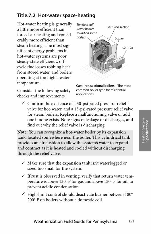
Hea
ting
Sys
tem
Sp
ecifi
cati
ons
Weatherization Field Guide for Pennsylvania 151
Title.7.2 Hot-water space-heating
Hot-water heating is generally a little more efficient than forced-air heating and consid-erably more efficient than steam heating. The most sig-nificant energy problems in hot-water systems are poor steady-state efficiency, off-cycle flue losses robbing heat from stored water, and boilers operating at too high a water temperature.
Consider the following safety checks and improvements.
Confirm the existence of a 30-psi-rated pressure-relief valve for hot-water, and a 15-psi-rated pressure relief valve for steam boilers. Replace a malfunctioning valve or add one if none exists. Note signs of leakage or discharges, and find out why the relief valve is discharging.
Make sure that the expansion tank isn’t waterlogged or sized too small for the system.
If rust is observed in venting, verify that return water tem-perature is above 130° F for gas and above 150° F for oil, to prevent acidic condensation.
High-limit control should deactivate burner between 180° 200° F on boilers without a domestic coil.
Cast-iron sectional boilers: The most common boiler type for residential applications.
cast-iron section
burner
Tankless coil water heater found on some boilers
controls
Note: You can recognize a hot-water boiler by its expansion tank, located somewhere near the boiler. This cylindrical tank provides an air cushion to allow the system’s water to expand and contract as it is heated and cooled without discharging through the relief valve.

Hea
ting
Sys
tem
Sp
ecifi
cati
ons
152
Lubricate circulator pump(s) if necessary.
Consider the following efficiency improvements.
Repair water leaks in the system.
Boiler should not have low-limit control for maintaining a minimum boiler-water temperature, unless the boiler is heating domestic water in addition to space heating.
Bleed air from radiators and piping through air vents on piping or radiators on hot water systems. Most systems have an automatic fill valve. If there is a manual fill valve for refilling system with water, it should be open to push water in and air out, during air purging on hot water systems.
Consider installing outdoor reset controllers on larger boilers to regulate water temper-ature, depending on outdoor temperature.
After control improve-ments like two-stage ther-mostats or reset controllers, verify that return water temperature is high enough to prevent condensation and corro-sion in the boiler and flue as noted previously.
Vacuum and clean fins of fin-tube convectors if you notice dust and dirt there.
Insulate all supply piping, passing through unheated
Purging air: Trapped air collects at the hot-water system’s highest parts. Bleeding air from radiators fills the radiator and gives it more heating surface area.
trapped air
air bleed valve
Vent dampers: Electric vent dampers close the chimney when the burner isn’t firing, preventing circulating air from carrying the boiler’s stored heat up the chimney.
A solenoid opens the damper and connects a switch in series with the burner.
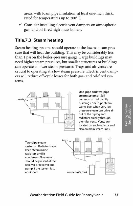
Hea
ting
Sys
tem
Sp
ecifi
cati
ons
Weatherization Field Guide for Pennsylvania 153
areas, with foam pipe insulation, at least one-inch thick, rated for temperatures up to 200° F.
Consider installing electric vent dampers on atmospheric gas- and oil-fired high-mass boilers.
Title.7.3 Steam heating
Steam heating systems should operate at the lowest steam pres-sure that will heat the building. This may be considerably less than 1 psi on the boiler-pressure gauge. Large buildings may need higher steam pressures, but smaller structures or buildings can operate at lower steam pressures. Traps and air vents are crucial to operating at a low steam pressure. Electric vent damp-ers will reduce off-cycle losses for both gas- and oil-fired sys-tems.
One-pipe and two-pipe steam systems: Still common in multifamily buildings, one-pipe steam works best when very low pressure steam can drive air out of the piping and radiators quickly through plentiful vents. Vents are located on each radiator and also on main steam lines.
condensate tank
vents
trapsTwo-pipe steam systems: Radiator traps keep steam inside radiators until it condenses. No steam should be present at the receiver or receiver and pump if the system is so equipped.
Hea
ting
Sys
tem
Sp
ecifi
cati
ons
154
Perform the following for safety and maintenance checks on steam systems.
Verify that steam boilers are equipped with high-pressure limits and low-water cut-off controls.
Verify that flush valves on low water cutoffs are operable and do not leak.
On steam boilers with externally mounted low water cut-offs, verify the function of the control by flushing the low water cutoff with the burner operating. Combustion must cease when the water level in the boiler drops below the level of the float.
Drain water out of blow-down valve until water runs clear.
Check with owner about chemicals added to boiler water to prevent corrosion and mineral deposits. Add chemicals if necessary.
Ask owner about instituting a schedule of blow-down and chemical-level checks.
Consider the following efficiency checks and improvements for steam systems.
Verify that high-pressure limit control is set at or below 1 (one) psi.
Verify steam vents are operable and that all steam radiators receive steam during every cycle. Replace vents as neces-sary. Add vents to steam lines and radiators as needed to achieve this goal.
Note: You can recognize a steam boiler by its sight glass, which will indicate the boiler’s water level. Notice that the water doesn’t completely fill the boiler, but instead allows a space for the steam to form above the boiler’s water.

Hea
ting
Sys
tem
Sp
ecifi
cati
ons
Weatherization Field Guide for Pennsylvania 155
Check steam traps with a digital thermometer or listening device to detect any steam escaping from radiators through the condensate return. Replace leaking steam traps or their thermostatic elements.
Repair leaks on the steam supply piping or on con-densate return piping.
Consider a flame-retention burner and electric vent damper as retrofits for steam boilers.
Clean fire side of heat exchanger of noticeable dirt.
All steam piping, passing through unconditioned areas, should be insulated to at least R-3 with fiber-glass or specially designed foam pipe insulation rated for steam piping.
Steam traps: Steam enters the steam trap heating its element and expanding the fluid inside. The expanded element plugs the steam’s escape with a valve.
steam first entering
expanding fluid
condensed water escaping
condensing steam
valve seated
valve un-seated
is trapped
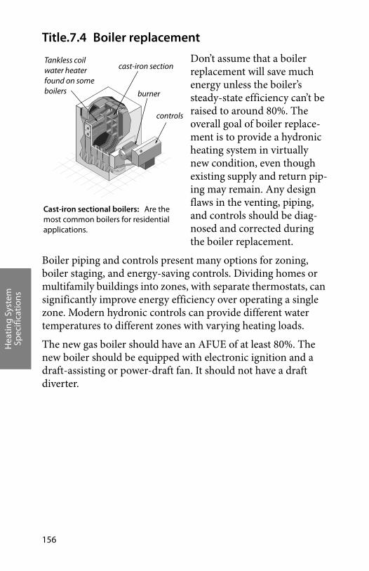
Hea
ting
Sys
tem
Sp
ecifi
cati
ons
156
Title.7.4 Boiler replacement
Don’t assume that a boiler replacement will save much energy unless the boiler’s steady-state efficiency can’t be raised to around 80%. The overall goal of boiler replace-ment is to provide a hydronic heating system in virtually new condition, even though existing supply and return pip-ing may remain. Any design flaws in the venting, piping, and controls should be diag-nosed and corrected during the boiler replacement.
Boiler piping and controls present many options for zoning, boiler staging, and energy-saving controls. Dividing homes or multifamily buildings into zones, with separate thermostats, can significantly improve energy efficiency over operating a single zone. Modern hydronic controls can provide different water temperatures to different zones with varying heating loads.
The new gas boiler should have an AFUE of at least 80%. The new boiler should be equipped with electronic ignition and a draft-assisting or power-draft fan. It should not have a draft diverter.
Cast-iron sectional boilers: Are the most common boilers for residential applications.
cast-iron section
burner
Tankless coil water heater found on some boilers
controls
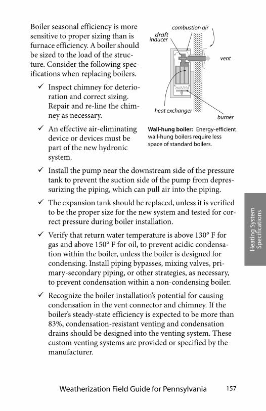
Hea
ting
Sys
tem
Sp
ecifi
cati
ons
Weatherization Field Guide for Pennsylvania 157
Boiler seasonal efficiency is more sensitive to proper sizing than is furnace efficiency. A boiler should be sized to the load of the struc-ture. Consider the following spec-ifications when replacing boilers.
Inspect chimney for deterio-ration and correct sizing. Repair and re-line the chim-ney as necessary.
An effective air-eliminating device or devices must be part of the new hydronic system.
Install the pump near the downstream side of the pressure tank to prevent the suction side of the pump from depres-surizing the piping, which can pull air into the piping.
The expansion tank should be replaced, unless it is verified to be the proper size for the new system and tested for cor-rect pressure during boiler installation.
Verify that return water temperature is above 130° F for gas and above 150° F for oil, to prevent acidic condensa-tion within the boiler, unless the boiler is designed for condensing. Install piping bypasses, mixing valves, pri-mary-secondary piping, or other strategies, as necessary, to prevent condensation within a non-condensing boiler.
Recognize the boiler installation’s potential for causing condensation in the vent connector and chimney. If the boiler’s steady-state efficiency is expected to be more than 83%, condensation-resistant venting and condensation drains should be designed into the venting system. These custom venting systems are provided or specified by the manufacturer.
vent
combustion air
burnerheat exchanger
Wall-hung boiler: Energy-efficient wall-hung boilers require less space of standard boilers.
draft inducer
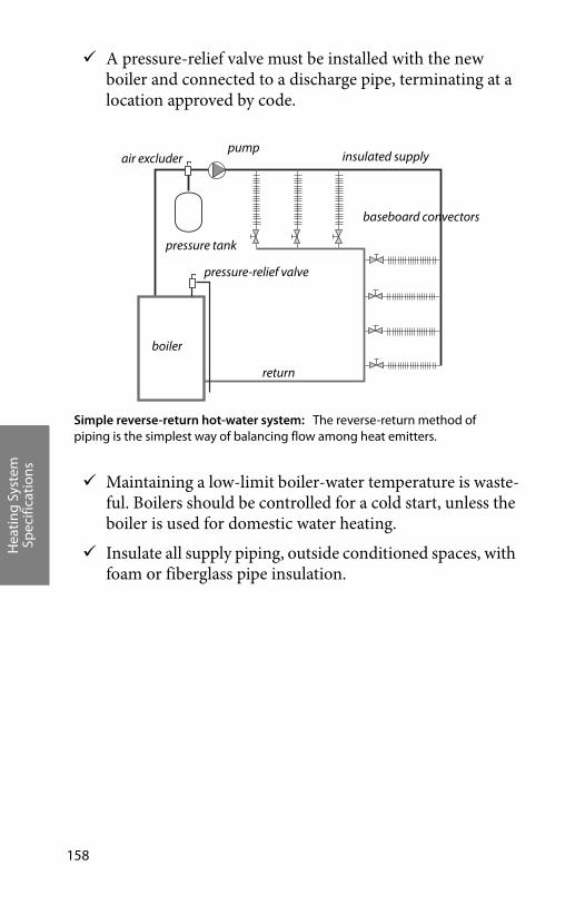
Hea
ting
Sys
tem
Sp
ecifi
cati
ons
158
A pressure-relief valve must be installed with the new boiler and connected to a discharge pipe, terminating at a location approved by code.
Maintaining a low-limit boiler-water temperature is waste-ful. Boilers should be controlled for a cold start, unless the boiler is used for domestic water heating.
Insulate all supply piping, outside conditioned spaces, with foam or fiberglass pipe insulation.
baseboard convectors
pressure tank
pumpair excluder
boiler
pressure-relief valve
return
insulated supply
Simple reverse-return hot-water system: The reverse-return method of piping is the simplest way of balancing flow among heat emitters.

Hea
ting
Sys
tem
Sp
ecifi
cati
ons
Weatherization Field Guide for Pennsylvania 159
Extend new piping and radiators to conditioned areas like additions and finished basements, cur-rently heated by space heaters.
For large boilers, consider installing outdoor reset controllers to adjust sup-ply water temperature according to outdoor tem-perature.
For large boilers, consider installing a cutout controller that prevents the boiler from firing when the outdoor tem-perature is above a certain setpoint where heat is not needed.
Reset controller: The circulating water is controlled by the reset controller according to the outdoor temperature.
outdoor sensorreset controller
aquastat boiler-water temperature sensor
Hea
ting
Sys
tem
Sp
ecifi
cati
ons
160
Air-
Seal
ing
and
Insu
lati
ng
Weatherization Field Guide for Pennsylvania 161
CHAPTER TITLE: AIR-SEALING AND INSULATING
A building’s thermal boundary consists of an air barrier and insulation which must be in continuous contact with each other. The thermal boundary should surround occupied or unoccu-pied conditioned space but it may include unconditioned spaces such as where the heating system is located. These measures improve the building’s thermal boundary.
Perform air leakage testing and evaluation before beginning air-sealing or insulation work. See “Diagnosing Shell & Duct Air Leakage” on page 199.
Use visual inspection to determine the cost-effectiveness of add-ing thermal resistance to a building. Reducing air leakage and adding insulation use the same general approach–the most criti-cal areas are retrofitted first and then less needy areas are retro-fitted as time and budget permit.
Air-sealing may also be undertaken to reduce the flow of mois-ture into building cavities. Evaluate all insulation and air sealing measures using the PA WAP Single Family Home Measure Selection Priority List on page 19.
TITLE.1 REDUCING AIR LEAKAGE
Air leakage in homes accounts for up to 40% of annual heating costs. Air-leakage reduction is one of weatherization’s most important functions, and often the most difficult.
The primary goals of air-leakage reduction are to:
1. Avoid moisture migration into building cavities
2. Protect insulation’s thermal resistance
3. Increase comfort
4. Save energy
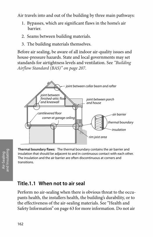
Air-
Seal
ing
and
Insu
lati
ng
162
Air travels into and out of the building by three main pathways:
1. Bypasses, which are significant flaws in the home’s air barrier.
2. Seams between building materials.
3. The building materials themselves.
Before air sealing, be aware of all indoor air-quality issues and house-pressure hazards. State and local governments may set standards for airtightness levels and ventilation. See “Building Airflow Standard (BAS)” on page 207.
Title.1.1 When not to air seal
Perform no air-sealing when there is obvious threat to the occu-pants health, the installers health, the building’s durability, or to the effectiveness of the air-sealing materials. See “Health and Safety Information” on page 63 for more information. Do not air
Thermal boundary flaws: The thermal boundary contains the air barrier and insulation that should be adjacent to and in continuous contact with each other. The insulation and the air barrier are often discontinuous at corners and transitions.
rim joist area
joint between collar beam and rafter
cantilevered floorcorner at garage ceiling
insulation
air barrier
thermal boundary
joint between porch and house
joint between finished-attic floor and kneewall
Air-
Seal
ing
and
Insu
lati
ng
Weatherization Field Guide for Pennsylvania 163
seal when the following conditions are present or until they have been corrected:
1. Moisture has caused structural damage, rot, mold or mildew growth.
2. Fire hazards place the building’s life and occupant safety in jeopardy.
3. Measured carbon monoxide level exceeds suggested action level.
4. Chimney drafts of combustion appliances don’t meet minimum standards.
5. A permanently mounted unvented fossil fuel fired heater is used as a primary heating source.
6. The building is already at or below its Building Airflow Standard, and no mechanical ventilation exists or is planned.
7. The client indicates that they intend to use portable fos-sil-fuel-fired heaters.
Title.1.2 Sealing bypasses
Major air sealing includes sealing bypasses and other relatively large openings between the conditioned and unconditioned space. Major air sealing activities are generally completed prior to other shell measure activities, and usually result in a signifi-cant drop in the blower door reading and/or changes in pressure diagnostics readings.
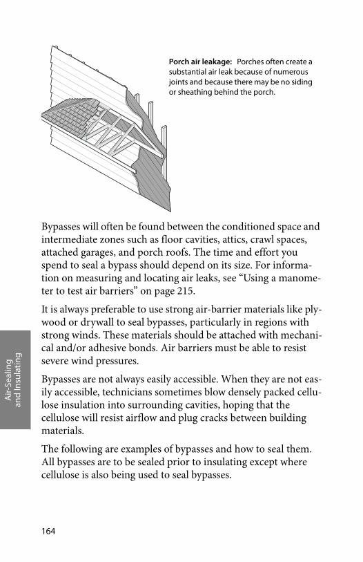
Air-
Seal
ing
and
Insu
lati
ng
164
Bypasses will often be found between the conditioned space and intermediate zones such as floor cavities, attics, crawl spaces, attached garages, and porch roofs. The time and effort you spend to seal a bypass should depend on its size. For informa-tion on measuring and locating air leaks, see “Using a manome-ter to test air barriers” on page 215.
It is always preferable to use strong air-barrier materials like ply-wood or drywall to seal bypasses, particularly in regions with strong winds. These materials should be attached with mechani-cal and/or adhesive bonds. Air barriers must be able to resist severe wind pressures.
Bypasses are not always easily accessible. When they are not eas-ily accessible, technicians sometimes blow densely packed cellu-lose insulation into surrounding cavities, hoping that the cellulose will resist airflow and plug cracks between building materials.
The following are examples of bypasses and how to seal them. All bypasses are to be sealed prior to insulating except where cellulose is also being used to seal bypasses.
Porch air leakage: Porches often create a substantial air leak because of numerous joints and because there may be no siding or sheathing behind the porch.
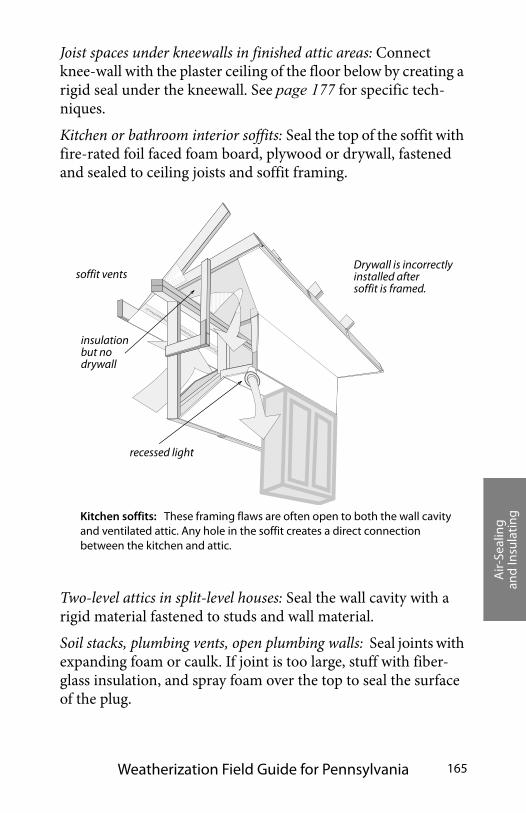
Air-
Seal
ing
and
Insu
lati
ng
Weatherization Field Guide for Pennsylvania 165
Joist spaces under kneewalls in finished attic areas: Connect knee-wall with the plaster ceiling of the floor below by creating a rigid seal under the kneewall. See page 177 for specific tech-niques.
Kitchen or bathroom interior soffits: Seal the top of the soffit with fire-rated foil faced foam board, plywood or drywall, fastened and sealed to ceiling joists and soffit framing.
Two-level attics in split-level houses: Seal the wall cavity with a rigid material fastened to studs and wall material.
Soil stacks, plumbing vents, open plumbing walls: Seal joints with expanding foam or caulk. If joint is too large, stuff with fiber-glass insulation, and spray foam over the top to seal the surface of the plug.
Kitchen soffits: These framing flaws are often open to both the wall cavity and ventilated attic. Any hole in the soffit creates a direct connection between the kitchen and attic.
soffit vents
recessed light
insulationbut no drywall
Drywall is incorrectlyinstalled after soffit is framed.
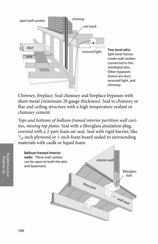
Air-
Seal
ing
and
Insu
lati
ng
166
Chimney, fireplace: Seal chimney and fireplace bypasses with sheet metal (minimum 28 gauge thickness). Seal to chimney or flue and ceiling structure with a high temperature sealant or chimney cement.
Tops and bottoms of balloon-framed interior partition wall cavi-ties, missing top plates: Seal with a fiberglass insulation plug, covered with a 2-part foam air-seal. Seal with rigid barrier, like 1/4-inch plywood or 1-inch foam board sealed to surrounding materials with caulk or liquid foam.
Two-level attic: Split-level homes create wall cavities connected to the ventilated attic. Other bypasses shown are duct, recessed light, and chimney.
ductrecessed light
chimney
soil stack
open wall cavities
wire
Balloon-framed interior walls: These wall cavities can be open to both the attic and basement.
interior wall
floor joist
fiberglassbatt
wall stud
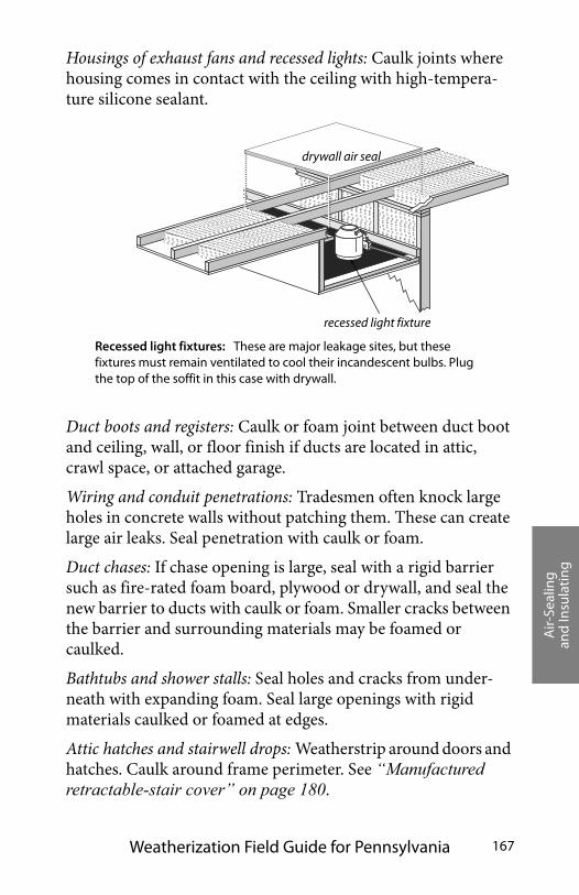
Air-
Seal
ing
and
Insu
lati
ng
Weatherization Field Guide for Pennsylvania 167
Housings of exhaust fans and recessed lights: Caulk joints where housing comes in contact with the ceiling with high-tempera-ture silicone sealant.
Duct boots and registers: Caulk or foam joint between duct boot and ceiling, wall, or floor finish if ducts are located in attic, crawl space, or attached garage.
Wiring and conduit penetrations: Tradesmen often knock large holes in concrete walls without patching them. These can create large air leaks. Seal penetration with caulk or foam.
Duct chases: If chase opening is large, seal with a rigid barrier such as fire-rated foam board, plywood or drywall, and seal the new barrier to ducts with caulk or foam. Smaller cracks between the barrier and surrounding materials may be foamed or caulked.
Bathtubs and shower stalls: Seal holes and cracks from under-neath with expanding foam. Seal large openings with rigid materials caulked or foamed at edges.
Attic hatches and stairwell drops: Weatherstrip around doors and hatches. Caulk around frame perimeter. See “Manufactured retractable-stair cover” on page 180.
Recessed light fixtures: These are major leakage sites, but these fixtures must remain ventilated to cool their incandescent bulbs. Plug the top of the soffit in this case with drywall.
drywall air seal
recessed light fixture

Air-
Seal
ing
and
Insu
lati
ng
168
Other openings in the air barrier: Seal with rigid material, caulk, spray foam, or expanding foam depending upon size and nature of opening.
Pocket Door Wall Cavity: When located on the second floor, cap the top of the entire wall cavity in the attic with rigid board, caulked and stapled. Where wall cavities containing the retracted pocket door halves connect with exterior framed walls, stuff narrow strips of unfaced fiber-glass batts into the door opening with a broom handle far enough to allow for complete opening of the door.
Pocket doors: Care should be taken that insulation and air sealing procedures do not hinder the operation of the door.
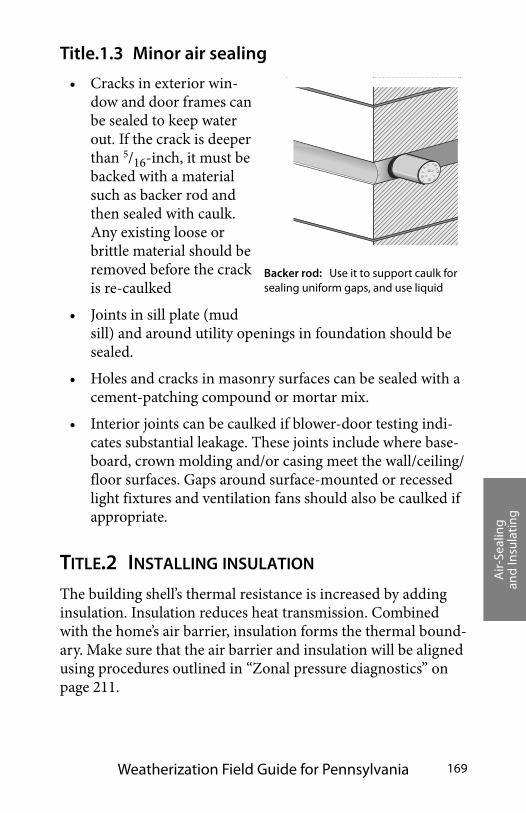
Air-
Seal
ing
and
Insu
lati
ng
Weatherization Field Guide for Pennsylvania 169
Title.1.3 Minor air sealing
• Cracks in exterior win-dow and door frames can be sealed to keep water out. If the crack is deeper than 5/16-inch, it must be backed with a material such as backer rod and then sealed with caulk. Any existing loose or brittle material should be removed before the crack is re-caulked
• Joints in sill plate (mud sill) and around utility openings in foundation should be sealed.
• Holes and cracks in masonry surfaces can be sealed with a cement-patching compound or mortar mix.
• Interior joints can be caulked if blower-door testing indi-cates substantial leakage. These joints include where base-board, crown molding and/or casing meet the wall/ceiling/floor surfaces. Gaps around surface-mounted or recessed light fixtures and ventilation fans should also be caulked if appropriate.
TITLE.2 INSTALLING INSULATION
The building shell’s thermal resistance is increased by adding insulation. Insulation reduces heat transmission. Combined with the home’s air barrier, insulation forms the thermal bound-ary. Make sure that the air barrier and insulation will be aligned using procedures outlined in “Zonal pressure diagnostics” on page 211.
Backer rod: Use it to support caulk for sealing uniform gaps, and use liquid
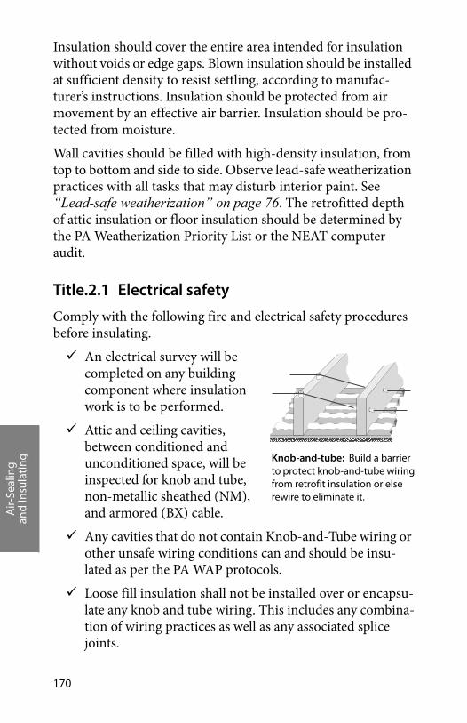
Air-
Seal
ing
and
Insu
lati
ng
170
Insulation should cover the entire area intended for insulation without voids or edge gaps. Blown insulation should be installed at sufficient density to resist settling, according to manufac-turer’s instructions. Insulation should be protected from air movement by an effective air barrier. Insulation should be pro-tected from moisture.
Wall cavities should be filled with high-density insulation, from top to bottom and side to side. Observe lead-safe weatherization practices with all tasks that may disturb interior paint. See “Lead-safe weatherization” on page 76. The retrofitted depth of attic insulation or floor insulation should be determined by the PA Weatherization Priority List or the NEAT computer audit.
Title.2.1 Electrical safety
Comply with the following fire and electrical safety procedures before insulating.
An electrical survey will be completed on any building component where insulation work is to be performed.
Attic and ceiling cavities, between conditioned and unconditioned space, will be inspected for knob and tube, non-metallic sheathed (NM), and armored (BX) cable.
Any cavities that do not contain Knob-and-Tube wiring or other unsafe wiring conditions can and should be insu-lated as per the PA WAP protocols.
Loose fill insulation shall not be installed over or encapsu-late any knob and tube wiring. This includes any combina-tion of wiring practices as well as any associated splice joints.
Knob-and-tube: Build a barrier to protect knob-and-tube wiringfrom retrofit insulation or else rewire to eliminate it.

Air-
Seal
ing
and
Insu
lati
ng
Weatherization Field Guide for Pennsylvania 171
Loose fill insulation, fiberglass batt or rigid board insula-tion may be installed up to or under the knob-and-tube wiring as to avoid encapsulating the wiring.
Air sealing may be performed on the building shell but should not come in contact or encapsulate open wiring splices.
All junction boxes shall be covered with steel covers designed for the size, type and intended use.
Identify the location of all cov-ered junction boxes. On floored attics, mark directly on the floor. On unfloored attic areas use a wire and flag.
Identify the circuit that powers the area where the insulation work is to be preformed and install appropriately sized S-type fuses.
Observe these safety guidelines for light fixtures.
Locate all ceiling fixtures in the attic and visually inspect the wiring connected to the fixture, fixture box or con-necting fitting. If insulation appears brittle or damaged do not allow insulation to come in contact with the fix-ture.inches from the fixture.
Recessed light fixtures that are not IC (insulation contact) rated must be covered with a box built from 5/8” fire-rated
S-type fuse: An S-type fuse won’t allow residents to oversize the fuse and overload a electrical circuit.
maintain 3-inch clearance
Covering recessed light fixtures: Covering recessed light fixtures with fire-rated 5/8” drywall or sheet-metal enclosures reduces air leakage and allows insulation to be blown around the box.
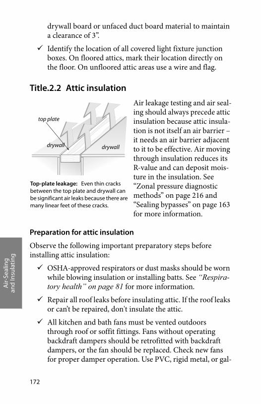
Air-
Seal
ing
and
Insu
lati
ng
172
drywall board or unfaced duct board material to maintain a clearance of 3”.
Identify the location of all covered light fixture junction boxes. On floored attics, mark their location directly on the floor. On unfloored attic areas use a wire and flag.
Title.2.2 Attic insulation
Air leakage testing and air seal-ing should always precede attic insulation because attic insula-tion is not itself an air barrier – it needs an air barrier adjacent to it to be effective. Air moving through insulation reduces its R-value and can deposit mois-ture in the insulation. See “Zonal pressure diagnostic methods” on page 216 and “Sealing bypasses” on page 163 for more information.
Preparation for attic insulation
Observe the following important preparatory steps before installing attic insulation:
OSHA-approved respirators or dust masks should be worn while blowing insulation or installing batts. See “Respira-tory health” on page 81 for more information.
Repair all roof leaks before insulating attic. If the roof leaks or can’t be repaired, don't insulate the attic.
All kitchen and bath fans must be vented outdoors through roof or soffit fittings. Fans without operating backdraft dampers should be retrofitted with backdraft dampers, or the fan should be replaced. Check new fans for proper damper operation. Use PVC, rigid metal, or gal-
Top-plate leakage: Even thin cracks between the top plate and drywall can be significant air leaks because there are many linear feet of these cracks.
top plate
drywall drywall
Air-
Seal
ing
and
Insu
lati
ng
Weatherization Field Guide for Pennsylvania 173
vanized pipe for venting whenever possible, and insulate the pipe to prevent condensation. Do not use flexible plas-tic ducting.
Install collars or dams around masonry chimneys, B-vent chimneys, and manufactured chimneys after sealing bypass.
All-fuel wood-stove chimneys should have ventilated insu-lation shields to prevent insulation from touching the chimney.
If you plan to cover an electrical junction box with insula-tion, mark its location with a sign or other means.
If sheet metal is used as a barrier around heating produc-ing devices or chimneys, it must be fastened securely to the ceiling joist so the barrier won’t collapse. Barriers should extend at least 4 inches above the insulation and be secured to keep insulation a minimum of 3 inches away from the heat-producing device.
If insulation is to cover wiring, inspect fuse boxes to ensure that wiring isn’t overloaded.
Knob-and-tube wiring should not be covered with retrofit insulation.
Install S-type fuses where appropriate to prevent circuit overloading. Maximum ampacity for 14-gauge wire is 15 amps and for 12-gauge wire is 20 amps.
Install chutes, dams, tubes, or other blocking materials to prevent blown insulation from plugging air channels between soffit vents and the attic. These chutes or other devices maximize the amount of insulation that may be
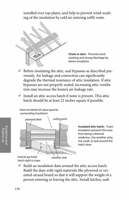
Air-
Seal
ing
and
Insu
lati
ng
174
installed over top plates, and help to prevent wind-wash-ing of the insulation by cold air entering soffit vents.
Before insulating the attic, seal bypasses as described pre-viously. Air leakage and convection can significantly degrade the thermal resistance of attic insulation. If attic bypasses are not properly sealed, increasing attic ventila-tion may increase the home’s air-leakage rate.
Install an attic access hatch if none is present. This attic hatch should be at least 22 inches square if possible.
Build an insulation dam around the attic access hatch. Build the dam with rigid materials like plywood or ori-ented-strand board so that it will support the weight of a person entering or leaving the attic. Install latches, sash
Chute or dam: Prevents wind washing and airway blockage by blown insulation.
ceiling joists
hook & eye holds hatch tight to stops
foam insulation (R-value equal to surrounding insulation)
plywood dam
weather strip
Insulated attic hatch: Foam insulation prevents this area from being a thermal weakness. Use weather strip, not caulk, to seal around the hatch door.
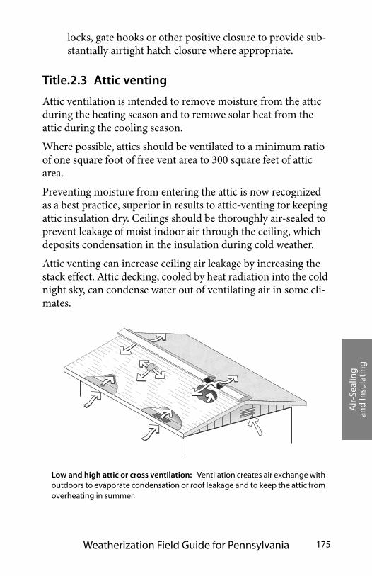
Air-
Seal
ing
and
Insu
lati
ng
Weatherization Field Guide for Pennsylvania 175
locks, gate hooks or other positive closure to provide sub-stantially airtight hatch closure where appropriate.
Title.2.3 Attic venting
Attic ventilation is intended to remove moisture from the attic during the heating season and to remove solar heat from the attic during the cooling season.
Where possible, attics should be ventilated to a minimum ratio of one square foot of free vent area to 300 square feet of attic area.
Preventing moisture from entering the attic is now recognized as a best practice, superior in results to attic-venting for keeping attic insulation dry. Ceilings should be thoroughly air-sealed to prevent leakage of moist indoor air through the ceiling, which deposits condensation in the insulation during cold weather.
Attic venting can increase ceiling air leakage by increasing the stack effect. Attic decking, cooled by heat radiation into the cold night sky, can condense water out of ventilating air in some cli-mates.
Low and high attic or cross ventilation: Ventilation creates air exchange with outdoors to evaporate condensation or roof leakage and to keep the attic from overheating in summer.
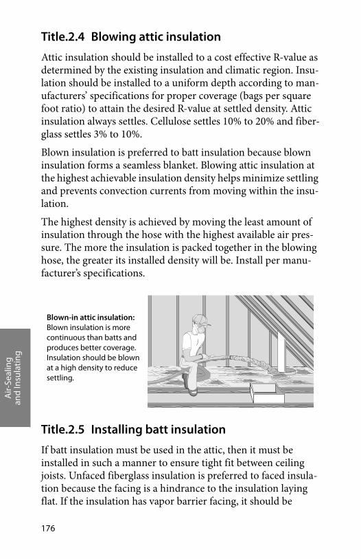
Air-
Seal
ing
and
Insu
lati
ng
176
Title.2.4 Blowing attic insulation
Attic insulation should be installed to a cost effective R-value as determined by the existing insulation and climatic region. Insu-lation should be installed to a uniform depth according to man-ufacturers’ specifications for proper coverage (bags per square foot ratio) to attain the desired R-value at settled density. Attic insulation always settles. Cellulose settles 10% to 20% and fiber-glass settles 3% to 10%.
Blown insulation is preferred to batt insulation because blown insulation forms a seamless blanket. Blowing attic insulation at the highest achievable insulation density helps minimize settling and prevents convection currents from moving within the insu-lation.
The highest density is achieved by moving the least amount of insulation through the hose with the highest available air pres-sure. The more the insulation is packed together in the blowing hose, the greater its installed density will be. Install per manu-facturer’s specifications.
Title.2.5 Installing batt insulation
If batt insulation must be used in the attic, then it must be installed in such a manner to ensure tight fit between ceiling joists. Unfaced fiberglass insulation is preferred to faced insula-tion because the facing is a hindrance to the insulation laying flat. If the insulation has vapor barrier facing, it should be
Blown-in attic insulation: Blown insulation is more continuous than batts and produces better coverage. Insulation should be blown at a high density to reduce settling.
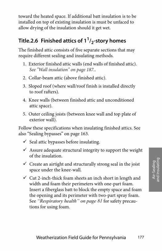
Air-
Seal
ing
and
Insu
lati
ng
Weatherization Field Guide for Pennsylvania 177
toward the heated space. If additional batt insulation is to be installed on top of existing insulation is must be unfaced to allow drying of the insulation should it get wet.
Title.2.6 Finished attics of 11/2-story homes
The finished attic consists of five separate sections that may require different sealing and insulating methods.
1. Exterior finished attic walls (end walls of finished attic). See "Wall insulation" on page 187..
2. Collar-beam attic (above finished attic).
3. Sloped roof (where wall/roof finish is installed directly to roof rafters).
4. Knee walls (between finished attic and unconditioned attic space).
5. Outer ceiling joists (between knee wall and top plate of exterior wall).
Follow these specifications when insulating finished attics. See also “Sealing bypasses” on page 163.
Seal attic bypasses before insulating.
Assure adequate structural integrity to support the weight of the insulation.
Create an airtight and structurally strong seal in the joist space under the knee-wall.
Cut 2-inch-thick foam sheets an inch short in length and width and foam their perimeters with one-part foam. Insert a fiberglass batt to block the empty space and foam the opening and its perimeter with two-part spray foam. See “Respiratory health” on page 81 for safety precau-tions for using foam.
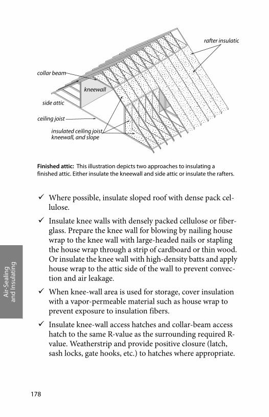
Air-
Seal
ing
and
Insu
lati
ng
178
Where possible, insulate sloped roof with dense pack cel-lulose.
Insulate knee walls with densely packed cellulose or fiber-glass. Prepare the knee wall for blowing by nailing house wrap to the knee wall with large-headed nails or stapling the house wrap through a strip of cardboard or thin wood. Or insulate the knee wall with high-density batts and apply house wrap to the attic side of the wall to prevent convec-tion and air leakage.
When knee-wall area is used for storage, cover insulation with a vapor-permeable material such as house wrap to prevent exposure to insulation fibers.
Insulate knee-wall access hatches and collar-beam access hatch to the same R-value as the surrounding required R-value. Weatherstrip and provide positive closure (latch, sash locks, gate hooks, etc.) to hatches where appropriate.
Finished attic: This illustration depicts two approaches to insulating a finished attic. Either insulate the kneewall and side attic or insulate the rafters.
rafter insulatio
side attic
kneewall
collar beam
ceiling joist
insulated ceiling joist, kneewall, and slope
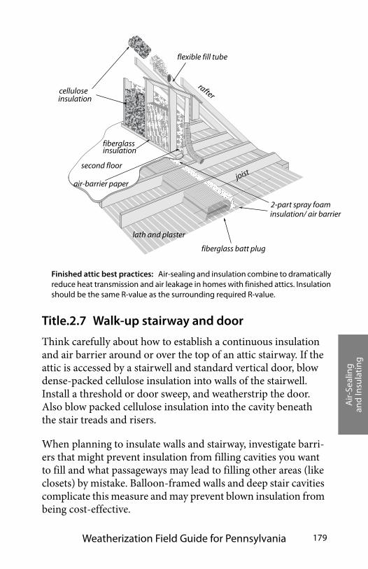
Air-
Seal
ing
and
Insu
lati
ng
Weatherization Field Guide for Pennsylvania 179
Title.2.7 Walk-up stairway and door
Think carefully about how to establish a continuous insulation and air barrier around or over the top of an attic stairway. If the attic is accessed by a stairwell and standard vertical door, blow dense-packed cellulose insulation into walls of the stairwell. Install a threshold or door sweep, and weatherstrip the door. Also blow packed cellulose insulation into the cavity beneath the stair treads and risers.
When planning to insulate walls and stairway, investigate barri-ers that might prevent insulation from filling cavities you want to fill and what passageways may lead to filling other areas (like closets) by mistake. Balloon-framed walls and deep stair cavities complicate this measure and may prevent blown insulation from being cost-effective.
flexible fill tube
lath and plaster
second floor
celluloseinsulation
fiberglassinsulation
joist
rafter
fiberglass batt plug
2-part spray foam
air-barrier paper
Finished attic best practices: Air-sealing and insulation combine to dramatically reduce heat transmission and air leakage in homes with finished attics. Insulation should be the same R-value as the surrounding required R-value.
insulation/ air barrier
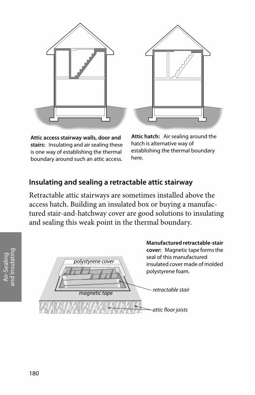
Air-
Seal
ing
and
Insu
lati
ng
180
Insulating and sealing a retractable attic stairway
Retractable attic stairways are sometimes installed above the access hatch. Building an insulated box or buying a manufac-tured stair-and-hatchway cover are good solutions to insulating and sealing this weak point in the thermal boundary.
Attic access stairway walls, door and stairs: Insulating and air sealing these is one way of establishing the thermal boundary around such an attic access.
Attic hatch: Air sealing around the hatch is alternative way of establishing the thermal boundary here.
retractable stair
polystyrene cover
magnetic tape
attic floor joists
Manufactured retractable-stair cover: Magnetic tape forms the seal of this manufactured insulated cover made of molded polystyrene foam.
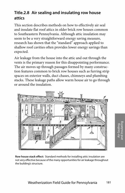
Air-
Seal
ing
and
Insu
lati
ng
Weatherization Field Guide for Pennsylvania 181
Title.2.8 Air sealing and insulating row house attics
This section describes methods on how to effectively air seal and insulate flat roof attics in older brick row houses common to Southeastern Pennsylvania. Although attic insulation may seem to be a very straightforward energy saving measure, research has shown that the “standard” approach applied to shallow roof cavities often provides lower energy savings than expected.
Air leakage from the house into the attic and out through the vents is the primary reason for this disappointing performance. The air moves up through passages formed by many construc-tion features common to brick row houses such as furring strip spaces on exterior walls, duct chases, chimneys and plumbing stacks. These leakage paths allow warm house air to go through or around the insulation.
Row house stack effect: Standard methods for installing attic insulation are not very effective because of the many opportunities for air leakage throughout the building’s structure.
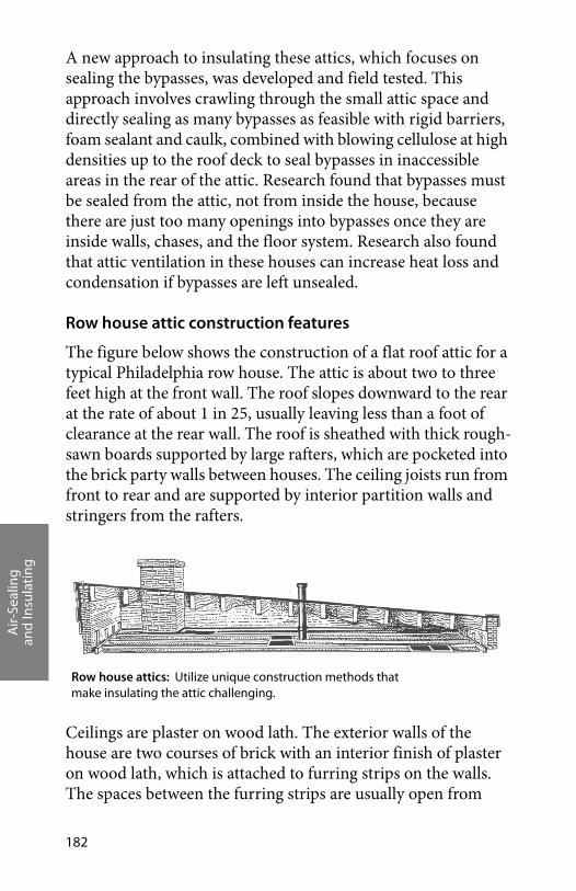
Air-
Seal
ing
and
Insu
lati
ng
182
A new approach to insulating these attics, which focuses on sealing the bypasses, was developed and field tested. This approach involves crawling through the small attic space and directly sealing as many bypasses as feasible with rigid barriers, foam sealant and caulk, combined with blowing cellulose at high densities up to the roof deck to seal bypasses in inaccessible areas in the rear of the attic. Research found that bypasses must be sealed from the attic, not from inside the house, because there are just too many openings into bypasses once they are inside walls, chases, and the floor system. Research also found that attic ventilation in these houses can increase heat loss and condensation if bypasses are left unsealed.
Row house attic construction features
The figure below shows the construction of a flat roof attic for a typical Philadelphia row house. The attic is about two to three feet high at the front wall. The roof slopes downward to the rear at the rate of about 1 in 25, usually leaving less than a foot of clearance at the rear wall. The roof is sheathed with thick rough-sawn boards supported by large rafters, which are pocketed into the brick party walls between houses. The ceiling joists run from front to rear and are supported by interior partition walls and stringers from the rafters.
Ceilings are plaster on wood lath. The exterior walls of the house are two courses of brick with an interior finish of plaster on wood lath, which is attached to furring strips on the walls. The spaces between the furring strips are usually open from
Row house attics: Utilize unique construction methods that make insulating the attic challenging.
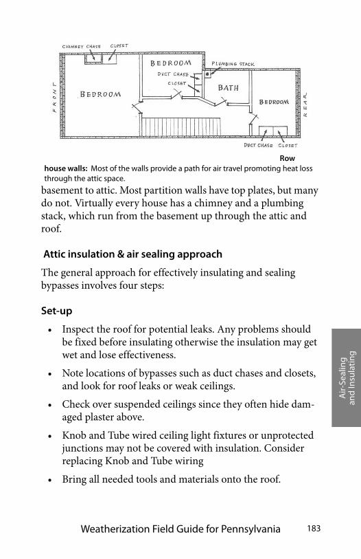
Air-
Seal
ing
and
Insu
lati
ng
Weatherization Field Guide for Pennsylvania 183
basement to attic. Most partition walls have top plates, but many do not. Virtually every house has a chimney and a plumbing stack, which run from the basement up through the attic and roof.
Attic insulation & air sealing approach
The general approach for effectively insulating and sealing bypasses involves four steps:
Set-up
• Inspect the roof for potential leaks. Any problems should be fixed before insulating otherwise the insulation may get wet and lose effectiveness.
• Note locations of bypasses such as duct chases and closets, and look for roof leaks or weak ceilings.
• Check over suspended ceilings since they often hide dam-aged plaster above.
• Knob and Tube wired ceiling light fixtures or unprotected junctions may not be covered with insulation. Consider replacing Knob and Tube wiring
• Bring all needed tools and materials onto the roof.
Row house walls: Most of the walls provide a path for air travel promoting heat loss through the attic space.
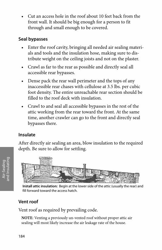
Air-
Seal
ing
and
Insu
lati
ng
184
• Cut an access hole in the roof about 10 feet back from the front wall. It should be big enough for a person to fit through and small enough to be covered.
Seal bypasses
• Enter the roof cavity, bringing all needed air sealing materi-als and tools and the insulation hose, making sure to dis-tribute weight on the ceiling joists and not on the plaster.
• Crawl as far to the rear as possible and directly seal all accessible rear bypasses.
• Dense pack the rear wall perimeter and the tops of any inaccessible rear chases with cellulose at 3.5 lbs. per cubic foot density. The entire unreachable rear section should be filled to the roof deck with insulation.
• Crawl to and seal all accessible bypasses in the rest of the attic working from the rear toward the front. At the same time, another crawler can go to the front and directly seal bypasses there.
Insulate
After directly air sealing an area, blow insulation to the required depth. Be sure to allow for settling.
Vent roof
Vent roof as required by prevailing code.NOTE: Venting a previously un-vented roof without proper attic air sealing will most likely increase the air leakage rate of the house.
Install attic insulation: Begin at the lower side of the attic (usually the rear) and fill forward toward the access hatch.

Air-
Seal
ing
and
Insu
lati
ng
Weatherization Field Guide for Pennsylvania 185
Research in Philadelphia found that when bypasses aren’t sealed, add-ing vents can negate much of the energy savings from the insulation because of the increased bypass air leakage caused by the vent open-ings. The vents tend to bring house air through the attic bringing moisture with it.
Special air sealing features
Row houses have many types of major air leakage sites in com-mon with other types of older housing stock. Examples include pocket doors, open topped partition walls, dropped ceilings, chimneys etc. There are some unique construction features about row houses and specific air sealing strategies that are worth mentioning here.
Furring strip channels
Exterior walls were built with vertical furring strips fastened to the brick and then the lath and plaster attached to the furring strips. The furring strips provide a break between potentially moist bricks and the interior plaster. Unfortunately, they also create an open channel from basement to attic about a half inch wide on all exterior walls. This channel allows air to leak from the basement and all penetrations in the wall (baseboards, elec-tric outlets, etc.) directly up into the attic.
Foam the tops of the channels between the furring strips. If the gap is very wide, insulation can be stuffed in the top and then foamed over.
Finish up: Vent roof as required by prevailing code. Turbine vents are not allowed.
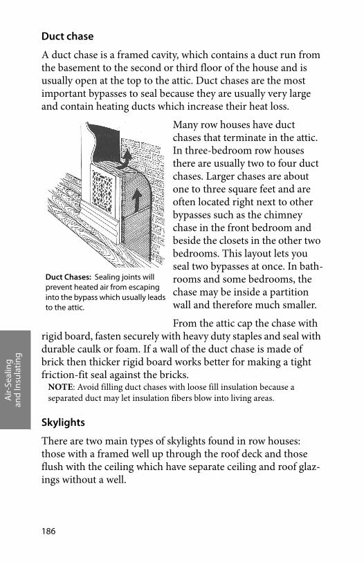
Air-
Seal
ing
and
Insu
lati
ng
186
Duct chase
A duct chase is a framed cavity, which contains a duct run from the basement to the second or third floor of the house and is usually open at the top to the attic. Duct chases are the most important bypasses to seal because they are usually very large and contain heating ducts which increase their heat loss.
Many row houses have duct chases that terminate in the attic. In three-bedroom row houses there are usually two to four duct chases. Larger chases are about one to three square feet and are often located right next to other bypasses such as the chimney chase in the front bedroom and beside the closets in the other two bedrooms. This layout lets you seal two bypasses at once. In bath-rooms and some bedrooms, the chase may be inside a partition wall and therefore much smaller.
From the attic cap the chase with rigid board, fasten securely with heavy duty staples and seal with durable caulk or foam. If a wall of the duct chase is made of brick then thicker rigid board works better for making a tight friction-fit seal against the bricks.
NOTE: Avoid filling duct chases with loose fill insulation because a separated duct may let insulation fibers blow into living areas.
Skylights
There are two main types of skylights found in row houses: those with a framed well up through the roof deck and those flush with the ceiling which have separate ceiling and roof glaz-ings without a well.
Duct Chases: Sealing joints will prevent heated air from escaping into the bypass which usually leads to the attic.

Air-
Seal
ing
and
Insu
lati
ng
Weatherization Field Guide for Pennsylvania 187
Row houses, which have the bathroom next to the front bed-room have a skylight with a well in the bathroom because there are no outside walls for a window to provide ventilation. In houses with this layout, the bathroom usually contains the chimney chase, plumbing stack, and sometimes a closet. The framed skylight well is leaky to the attic and is often made of vertical tongue-and-groove boards.
Some houses have skylights in the hallway, which are flush with the ceiling and have no enclosed well through the roof space. In this situation, there is another skylight in the roof deck posi-tioned above the one in the ceiling.
For skylight wells, the well should be sealed from the attic with caulk. The entire well should be insulated up to the roof deck with fiberglass batts (blown insulation can be used, but will usu-ally require a lot of material to reach the roof). In addition to sealing these leaks and insulating the perimeter of the well, it is a good energy saving investment to make an interior storm panel to fit over the bottom of the well at ceiling level. This panel can be made of acrylic and fastened with turn-clips, velcro, or mag-netic strips.
For skylights flush with the ceiling, sometimes called lay-lights, the preferred treatment is to build an insulated well from the ceiling to the roof. If this approach is considered too expensive and the homeowner wants to keep the skylight, then the lay-light should be well sealed, additional glazing panels placed over the glass, and a tall lip built up around the lay-light in the attic to stop insulation from covering it up.
Title.2.9 Wall insulation
Densely packed cellulose wall insulation reduces air leakage through cracks inside walls and other closed building cavities because the fibers are driven into the cracks by the blowing machine. Where possible, insulate at a density of 3.5 lbs./cu.ft.

Air-
Seal
ing
and
Insu
lati
ng
188
Install wall insulation with a uniform coverage and density. Wall cavities are like chimneys, and convection currents or air leak-age can significantly reduce the insulation’s thermal perfor-mance.
If you find the existing walls uninsulated or partially insulated, add insulation to provide complete coverage for all the home’s exterior walls.
Two methods for installing sidewall insulation are commonly used in Pennsylvania: dense-pack method (one-hole) or the two-hole method. The dense-pack method is preferred because it ensures that wall achieves an adequate coverage and density of insulation.
Inspecting walls
Inspect walls for evidence of moisture damage. If condi-tion of the siding, sheathing, or interior wall finish indi-cates an existing moisture problem, no sidewall insulation should be installed until the moisture problem has been identified and corrected.
Seal gaps in external window trim and other areas that may admit rain water into the wall.
Blowing insulation using a directional nozzle: Blowing insulation through one or two holes usually creates voids inside the wall cavity. Insulation won’t reliably blow at an adequate density more than about one foot from the nozzle. This is why tube-filling is recommended here.
interior wall
voids from settlinginsulation bridged and never filled bottom of cavity
Air-
Seal
ing
and
Insu
lati
ng
Weatherization Field Guide for Pennsylvania 189
Inspect indoor surfaces of exterior walls to assure that they are strong enough to withstand the force of insulation blowing.
Inspect for interior openings from which insulation may escape, such as pocket doors, balloon framing, un-backed cabinets, interior soffits, and closets. Seal openings as nec-essary to prevent insulation from escaping.
Ensure that exterior wall cavities used as return ducts are not filled with insulation.
Ensure that electrical circuits contained within walls aren’t overloaded. Maximum ampacity for 14 gauge copper wire is 15 amps and for 12 gauge copper wire is 20 amps. Install S-type fuses where appropriate to prevent circuit overload-ing.
Removing siding and drilling
Avoid drilling through siding. Where possible, carefully remove siding and drill through sheathing. This avoids the potential lead-paint hazard of drilling the siding. It also makes it easier to insert flexible fill tubes since the holes pass through one less layer of material.
If the siding cannot be removed, consider drilling the walls from inside the home. Obtain the owners permission before doing so, and practice lead-safe weatherization procedures. See “Lead-safe weatherization” on page 76.
Asbestos shingles may be carefully removed by pulling the nails holding them to the sheathing or else nipping off the nailheads. The shingles are brittle and break easily. Damp-ening the asbestos tiles keeps dust down. Wear a respirator when handling asbestos shingles.
Metal or vinyl siding may be removed with the aid of a zip tool.
Homes with brick veneer or blind-nailed asbestos siding may be insulated from the inside. Holes drilled for insula-
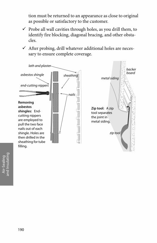
Air-
Seal
ing
and
Insu
lati
ng
190
tion must be returned to an appearance as close to original as possible or satisfactory to the customer.
Probe all wall cavities through holes, as you drill them, to identify fire blocking, diagonal bracing, and other obsta-cles.
After probing, drill whatever additional holes are neces-sary to ensure complete coverage.
Removing asbestos shingles: End-cutting nippers are employed to pull the two face nails out of each shingle. Holes are then drilled in the sheathing for tube filling.
asbestos shingle sheathing
lath and plaster
nails
end-cutting nippers
Zip tool: A zip tool separates the joint in metal siding.
zip tool
metal siding
backerboard
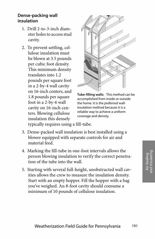
Air-
Seal
ing
and
Insu
lati
ng
Weatherization Field Guide for Pennsylvania 191
Dense-packing wall insulation
1. Drill 2-to-3-inch diam-eter holes to access stud cavity.
2. To prevent settling, cel-lulose insulation must be blown at 3.5 pounds per cubic foot density. This minimum density translates into 1.2 pounds per square foot in a 2-by-4 wall cavity on 16-inch centers, and 1.8 pounds per square foot in a 2-by-6 wall cavity on 16-inch cen-ters. Blowing cellulose insulation this densely typically requires using a fill-tube.
3. Dense-packed wall insulation is best installed using a blower equipped with separate controls for air and material feed.
4. Marking the fill-tube in one-foot intervals allows the person blowing insulation to verify the correct penetra-tion of the tube into the wall.
5. Starting with several full-height, unobstructed wall cav-ities allows the crew to measure the insulation density. Start with an empty hopper. Fill the hopper with a bag you’ve weighed. An 8-foot cavity should consume a minimum of 10 pounds of cellulose insulation.
Tube-filling walls: This method can be accomplished from inside or outside the home. It is the preferred wall-insulation method because it is a reliable way to achieve a uniform coverage and density.
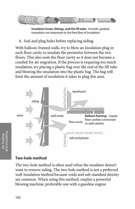
Air-
Seal
ing
and
Insu
lati
ng
192
6. Seal and plug holes before replacing siding.
With balloon-framed walls, try to blow an insulation plug in each floor cavity to insulate the perimeter between the two floors. This also seals the floor cavity so it does not become a conduit for air migration. If the process is requiring too much insulation, try placing a plastic bag over the end of the fill tube and blowing the insulation into the plastic bag. The bag will limit the amount of insulation it takes to plug this area.
Two-hole method
The two-hole method is often used when the insulator doesn’t want to remove siding. The two-hole method is not a preferred wall-insulation method because voids and sub-standard density are common. When using this method, employ a powerful blowing machine, preferably one with a gasoline engine.
Insulation hoses, fittings, and the fill tube: Smooth, gradual transitions are important to the free flow of insulation.
floor cavity
baseboard
wind wall cavity
siding
Balloon framing: Leaves floor cavities connected to wall cavities.
lath and plaster
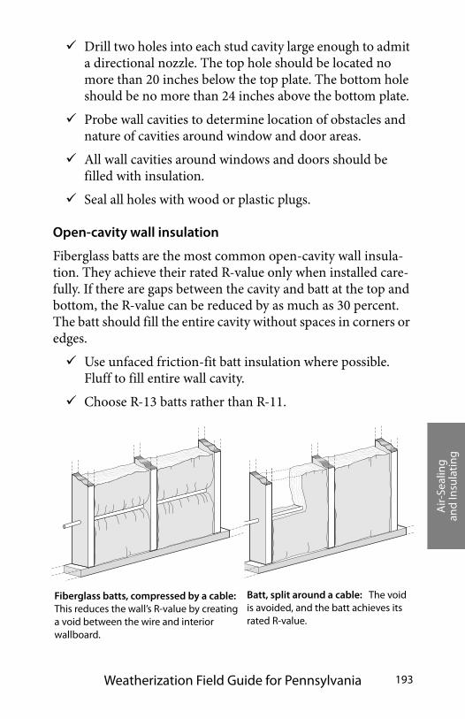
Air-
Seal
ing
and
Insu
lati
ng
Weatherization Field Guide for Pennsylvania 193
Drill two holes into each stud cavity large enough to admit a directional nozzle. The top hole should be located no more than 20 inches below the top plate. The bottom hole should be no more than 24 inches above the bottom plate.
Probe wall cavities to determine location of obstacles and nature of cavities around window and door areas.
All wall cavities around windows and doors should be filled with insulation.
Seal all holes with wood or plastic plugs.
Open-cavity wall insulation
Fiberglass batts are the most common open-cavity wall insula-tion. They achieve their rated R-value only when installed care-fully. If there are gaps between the cavity and batt at the top and bottom, the R-value can be reduced by as much as 30 percent. The batt should fill the entire cavity without spaces in corners or edges.
Use unfaced friction-fit batt insulation where possible. Fluff to fill entire wall cavity.
Choose R-13 batts rather than R-11.
Fiberglass batts, compressed by a cable: This reduces the wall’s R-value by creating a void between the wire and interior wallboard.
Batt, split around a cable: The void is avoided, and the batt achieves its rated R-value.
Air-
Seal
ing
and
Insu
lati
ng
194
Staple faced insulation to outside face of studs; avoid inset stapling.
Cut batt insulation to the exact length of the cavity. A too-short batt creates air spaces above and beneath the batt, allowing convection. A too-long batt will bunch up, creat-ing air pockets.
Split batt around wiring, rather than letting the wiring bunch the batt to one side of the cavity.
Insulate behind and around obstacles with scrap pieces of batt before installing batt.
Fiberglass insulation exposed to the interior living space must be covered with minimum 1/2-inch drywall or other material that has an ASTM flame spread rating of 25 or less.
Title.2.10 Floor insulation
Floor insulation is undertaken in conjunction with air-sealing to complete the thermal boundary at the base of the building. To establish an effective thermal boundary, the insulation and air barrier should be adjacent to each other and continuous. Estab-lishing an effective air barrier—comparable to the air barriers in the above-grade walls and ceiling—may be difficult. Further-more, floor insulation may or may not be cost-effective or prac-tical, considering the home’s weatherization budget and potential moisture problems.
With floor insulation, install a ground air/moisture barrier in crawl spaces and dirt-floor basements. Use six-mil plastic or cross laminated polyethylene. Any ducts from exhaust fans or clothes dryers that terminate in crawl spaces or basements should be extended to the outside.
Rim insulation and air-sealing
The joist spaces at the perimeter of the floor are a major weak point in the air barrier and insulation. Insulating and air-sealing
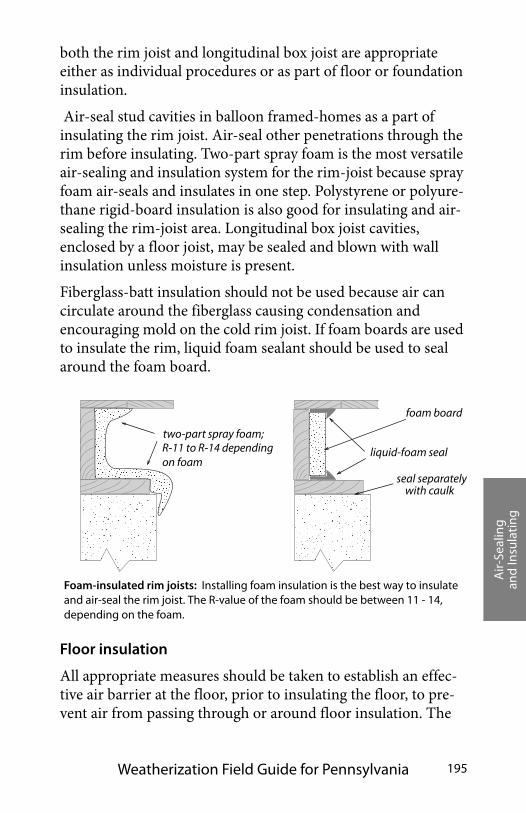
Air-
Seal
ing
and
Insu
lati
ng
Weatherization Field Guide for Pennsylvania 195
both the rim joist and longitudinal box joist are appropriate either as individual procedures or as part of floor or foundation insulation.
Air-seal stud cavities in balloon framed-homes as a part of insulating the rim joist. Air-seal other penetrations through the rim before insulating. Two-part spray foam is the most versatile air-sealing and insulation system for the rim-joist because spray foam air-seals and insulates in one step. Polystyrene or polyure-thane rigid-board insulation is also good for insulating and air-sealing the rim-joist area. Longitudinal box joist cavities, enclosed by a floor joist, may be sealed and blown with wall insulation unless moisture is present.
Fiberglass-batt insulation should not be used because air can circulate around the fiberglass causing condensation and encouraging mold on the cold rim joist. If foam boards are used to insulate the rim, liquid foam sealant should be used to seal around the foam board.
Floor insulation
All appropriate measures should be taken to establish an effec-tive air barrier at the floor, prior to insulating the floor, to pre-vent air from passing through or around floor insulation. The
Foam-insulated rim joists: Installing foam insulation is the best way to insulate and air-seal the rim joist. The R-value of the foam should be between 11 - 14, depending on the foam.
foam board
two-part spray foam;
liquid-foam seal
seal separately with caulk
R-11 to R-14 dependingon foam
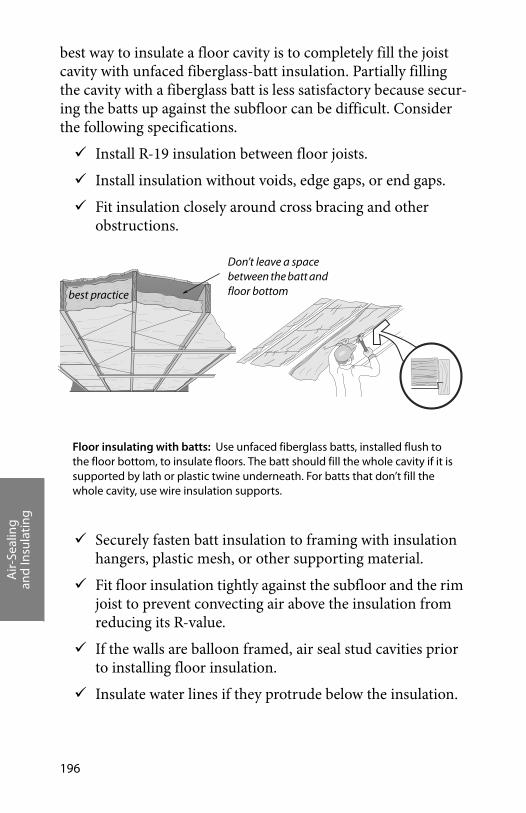
Air-
Seal
ing
and
Insu
lati
ng
196
best way to insulate a floor cavity is to completely fill the joist cavity with unfaced fiberglass-batt insulation. Partially filling the cavity with a fiberglass batt is less satisfactory because secur-ing the batts up against the subfloor can be difficult. Consider the following specifications.
Install R-19 insulation between floor joists.
Install insulation without voids, edge gaps, or end gaps.
Fit insulation closely around cross bracing and other obstructions.
Securely fasten batt insulation to framing with insulation hangers, plastic mesh, or other supporting material.
Fit floor insulation tightly against the subfloor and the rim joist to prevent convecting air above the insulation from reducing its R-value.
If the walls are balloon framed, air seal stud cavities prior to installing floor insulation.
Insulate water lines if they protrude below the insulation.
Floor insulating with batts: Use unfaced fiberglass batts, installed flush to the floor bottom, to insulate floors. The batt should fill the whole cavity if it is supported by lath or plastic twine underneath. For batts that don’t fill the whole cavity, use wire insulation supports.
Don’t leave a space between the batt and floor bottombest practice
Air-
Seal
ing
and
Insu
lati
ng
Weatherization Field Guide for Pennsylvania 197
Seal and insulate ducts remaining in the crawl space or unoccupied basement.
In crawl spaces, install a ground moisture barrier that runs up the foundation walls.
Ground moisture and air barriers
The ground is neither an air barrier nor a moisture barrier and can transport air and moisture into a crawl space. Crawl-space moisture can lead to condensation, mold, and rot. Air passing through the soil can also contain radon and pesticides. Covering the ground with an airtight moisture barrier establishes an air barrier and seals out moisture and soil gases.
Best practice involves sealing the seams in the ground moisture barrier with construction tape or acoustical sealant, making it both an air barrier and a moisture barrier. If the crawl-space access is difficult or if the air barrier is at the floor, the polyethyl-ene need not be sealed.
Crawl space ventilation
Crawl-space ventilation is generally not required if:
• There are no signs of standing water,
• The crawl space is dry,
• There is proper surface drainage, and
• There is a properly installed ground air-moisture barrier.
If the above conditions can’t be met, install one square foot of net free ventilation area for every 1500 square feet of crawl-space floor area. A minimum of two vents must be installed and should be located on opposite sides of the crawl space.
Air-
Seal
ing
and
Insu
lati
ng
198

Dia
gnos
ing
Shel
l &D
uct A
ir Le
akag
e
Weatherization Field Guide for Pennsylvania 199
CHAPTER TITLE: DIAGNOSING SHELL & DUCT AIR LEAKAGE
An air barrier, aligned with the insulation, forms the building’s thermal boundary. The home may or may not have an effective air barrier surrounding it. The testing described here will help you analyze the existing air barriers and decide whether and where air-sealing is needed. The energy impact of duct leakage depends on whether the ducts are located within or outside of the thermal boundary.
Controlling shell air leakage is the key ingredient in a successful weatherization job. Air leakage influences every aspect of weatherization. The decisions you make about sealing air leaks will affect a building dramatically throughout its lifetime. Con-sider the following major effects of air leakage.
• Air leakage creates up to 40% of a building’s heat loss.
• Air leakage can significantly reduce insulation R-value.
• Air leakage moves moisture into and out of the house, and exerts a wetting and/or drying effect.
• The type and amount of air leakage can determine whether or not a combustion appliance like a furnace or fireplace will vent its gases out the chimney as it should.
Furthermore, air leakage usually provides ventilation for exhausting pollutants and admitting fresh air. However, air leaks can bring pollutants in as easily as they let pollutants out.
Air-sealing or duct sealing may affect combustion-appliance venting by increasing house pressures or reducing the available supply of combustion air. After all weatherization materials have been installed, all crews or contractors should conduct worst-case draft testing and check the safety of all combustion appli-ances as described in “CAZ Combustion Safety Test” on page 103.
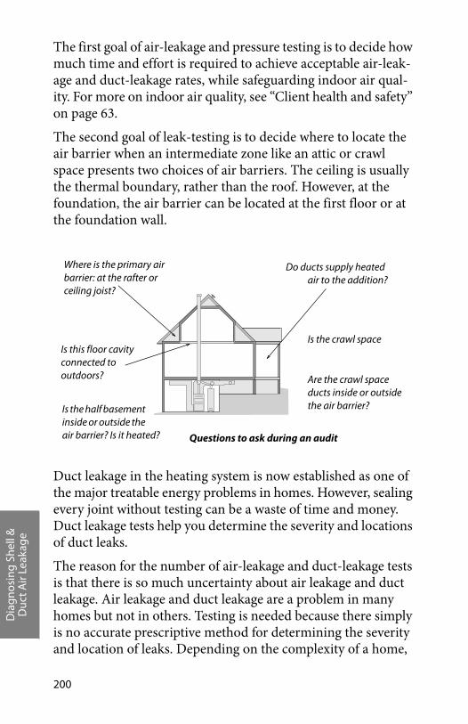
Dia
gnos
ing
Shel
l &D
uct A
ir Le
akag
e
200
The first goal of air-leakage and pressure testing is to decide how much time and effort is required to achieve acceptable air-leak-age and duct-leakage rates, while safeguarding indoor air qual-ity. For more on indoor air quality, see “Client health and safety” on page 63.
The second goal of leak-testing is to decide where to locate the air barrier when an intermediate zone like an attic or crawl space presents two choices of air barriers. The ceiling is usually the thermal boundary, rather than the roof. However, at the foundation, the air barrier can be located at the first floor or at the foundation wall.
Duct leakage in the heating system is now established as one of the major treatable energy problems in homes. However, sealing every joint without testing can be a waste of time and money. Duct leakage tests help you determine the severity and locations of duct leaks.
The reason for the number of air-leakage and duct-leakage tests is that there is so much uncertainty about air leakage and duct leakage. Air leakage and duct leakage are a problem in many homes but not in others. Testing is needed because there simply is no accurate prescriptive method for determining the severity and location of leaks. Depending on the complexity of a home,
Do ducts supply heated air to the addition?
Are the crawl space ducts inside or outside the air barrier?
Where is the primary air barrier: at the rafter or ceiling joist?
Is the half basement inside or outside the air barrier? Is it heated?
Is the crawl space Is this floor cavity connected to outdoors?
Questions to ask during an audit
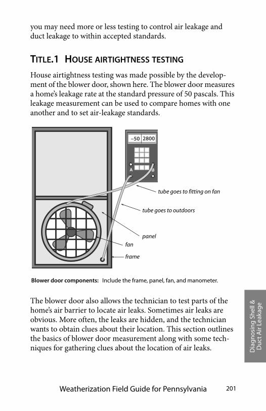
Dia
gnos
ing
Shel
l &D
uct A
ir Le
akag
e
Weatherization Field Guide for Pennsylvania 201
you may need more or less testing to control air leakage and duct leakage to within accepted standards.
TITLE.1 HOUSE AIRTIGHTNESS TESTING
House airtightness testing was made possible by the develop-ment of the blower door, shown here. The blower door measures a home’s leakage rate at the standard pressure of 50 pascals. This leakage measurement can be used to compare homes with one another and to set air-leakage standards.
The blower door also allows the technician to test parts of the home’s air barrier to locate air leaks. Sometimes air leaks are obvious. More often, the leaks are hidden, and the technician wants to obtain clues about their location. This section outlines the basics of blower door measurement along with some tech-niques for gathering clues about the location of air leaks.
A B
–50 2800
fan
frame
panel
tube goes to fitting on fan
Blower door components: Include the frame, panel, fan, and manometer.
tube goes to outdoors
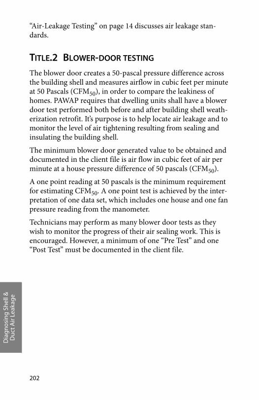
Dia
gnos
ing
Shel
l &D
uct A
ir Le
akag
e
202
“Air-Leakage Testing” on page 14 discusses air leakage stan-dards.
TITLE.2 BLOWER-DOOR TESTING The blower door creates a 50-pascal pressure difference across the building shell and measures airflow in cubic feet per minute at 50 Pascals (CFM50), in order to compare the leakiness of homes. PAWAP requires that dwelling units shall have a blower door test performed both before and after building shell weath-erization retrofit. It’s purpose is to help locate air leakage and to monitor the level of air tightening resulting from sealing and insulating the building shell.
The minimum blower door generated value to be obtained and documented in the client file is air flow in cubic feet of air per minute at a house pressure difference of 50 pascals (CFM50).
A one point reading at 50 pascals is the minimum requirement for estimating CFM50. A one point test is achieved by the inter-pretation of one data set, which includes one house and one fan pressure reading from the manometer.
Technicians may perform as many blower door tests as they wish to monitor the progress of their air sealing work. This is encouraged. However, a minimum of one “Pre Test” and one “Post Test” must be documented in the client file.
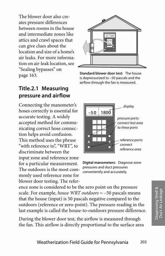
Dia
gnos
ing
Shel
l &D
uct A
ir Le
akag
e
Weatherization Field Guide for Pennsylvania 203
The blower door also cre-ates pressure differences between rooms in the house and intermediate zones like attics and crawl spaces that can give clues about the location and size of a home’s air leaks. For more informa-tion on air-leak location, see “Sealing bypasses” on page 163.
Title.2.1 Measuring pressure and airflow
Connecting the manometer’s hoses correctly is essential for accurate testing. A widely accepted method for commu-nicating correct hose connec-tion helps avoid confusion. This method uses the phrase “with reference to”, “WRT”, to discriminate between the input zone and reference zone for a particular measurement. The outdoors is the most com-monly used reference zone for blower door testing. The refer-ence zone is considered to be the zero point on the pressure scale. For example, house WRT outdoors = –50 pascals means that the house (input) is 50 pascals negative compared to the outdoors (reference or zero-point). The pressure reading in the last example is called the house-to-outdoors pressure difference.
During the blower door test, the airflow is measured through the fan. This airflow is directly proportional to the surface area
Standard blower door test: The house is depressurized to –50 pascals and the airflow through the fan is measured.
2. A B
–50 1800
A B
–50 1800pressure ports: connect test area to these ports
reference ports: connect reference area
display
Digital manometers: Diagnose zone pressures and duct pressures conveniently and accurately.
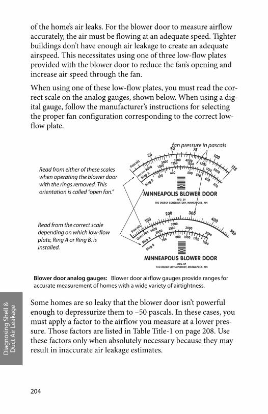
Dia
gnos
ing
Shel
l &D
uct A
ir Le
akag
e
204
of the home’s air leaks. For the blower door to measure airflow accurately, the air must be flowing at an adequate speed. Tighter buildings don’t have enough air leakage to create an adequate airspeed. This necessitates using one of three low-flow plates provided with the blower door to reduce the fan’s opening and increase air speed through the fan.
When using one of these low-flow plates, you must read the cor-rect scale on the analog gauges, shown below. When using a dig-ital gauge, follow the manufacturer’s instructions for selecting the proper fan configuration corresponding to the correct low-flow plate.
Some homes are so leaky that the blower door isn’t powerful enough to depressurize them to –50 pascals. In these cases, you must apply a factor to the airflow you measure at a lower pres-sure. Those factors are listed in Table Title-1 on page 208. Use these factors only when absolutely necessary because they may result in inaccurate air leakage estimates.
fan pressure in pascals
Read from either of these scales when operating the blower door with the rings removed. This orientation is called “open fan.”
Read from the correct scale depending on which low-flow plate, Ring A or Ring B, is installed.
Blower door analog gauges: Blower door airflow gauges provide ranges for accurate measurement of homes with a wide variety of airtightness.
Dia
gnos
ing
Shel
l &D
uct A
ir Le
akag
e
Weatherization Field Guide for Pennsylvania 205
Title.2.2 Preparing for a blower door test
Preparing the house for a blower door test involves putting the house in its heating operating condition with all conditioned zones open to the blower door. Try to anticipate safety problems that the blower door test could cause, particularly with combus-tion appliances.
• Identify the location of the thermal boundary and deter-mine which house zones are conditioned.
• Identify large air leaks that could prevent the blower door from achieving adequate house pressure.
• Survey pollutant sources that may pollute the air during a blower door test — wood stove or fireplace ashes for exam-ple.
• Put the house in its heating mode with windows and doors closed and air registers open.
• Turn off combustion appliances temporarily.
• Open interior doors so that all indoor areas inside the ther-mal boundary are connected to the blower door. This could include the basement, conditioned kneewall areas, and closets. Don’t open access doors between the home and its intermediate zones, which are outside the thermal bound-ary, such as attics, crawl spaces, and attached garages.
• Calculate house volume if you plan to use ACH50 (air changes per hour at 50 pascals) or ACHn (air changes per hour – natural). Calculate volume by multiplying length by width and then by height to arrive at the number of cubic feet of volume.
Adjusting for Baseline Pressure
To obtain accurate blower door measurements, you must cor-rect your target house pressure reading on the digital manome-ter to adjust for wind and stack effect. The most common digital manometers have a “Baseline” function that automatically can-

Dia
gnos
ing
Shel
l &D
uct A
ir Le
akag
e
206
cels the measurement effect of wind or stack pressures. Follow the manufacturer’s instructions about how to adjust the baseline pressure.
Adjust the measured pressure of older or simpler digital manometers by adding or subtracting pressure from the target blower door pressure of 50 pascals. A positive house pressure without blower door operation reduces the target blower door negative house pressure. A negative house pressure would increase the negative target blower door house pressure.
Block the blower door’s opening to prevent ambient airflow through the fan before measuring the baseline pressure. Make sure that the house-pressure hose is connected to outdoors and that the fan hose is connected. Measure the baseline house pres-sure with the blower door off.
If you read a positive house pressure of three pascals with refer-ence to outdoors, add those pascals to -50 pascals and set the house pressure at -47 pascals to get your accurate airflow (CFM50). If you read a negative house pressure of 2 pascals sub-tract those pascals from -50 pascals, and then set the blower door to produce -52 pascals to get your accurate airflow.
Title.2.3 Blower Door Test Procedures
Follow this general procedure when performing a blower door test.
+50–25–50–55 –5–45
Space is pressurized by wind
Space is depressurized by stack effect50 Pascals
50 Pascals
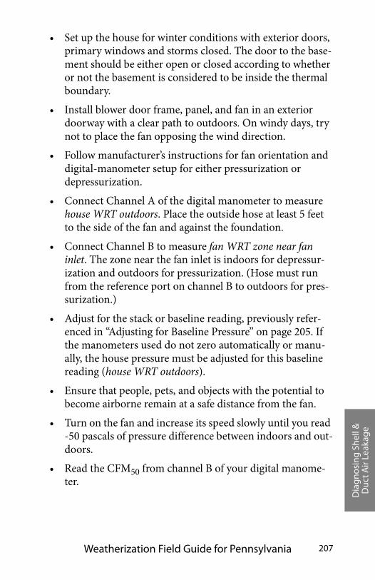
Dia
gnos
ing
Shel
l &D
uct A
ir Le
akag
e
Weatherization Field Guide for Pennsylvania 207
• Set up the house for winter conditions with exterior doors, primary windows and storms closed. The door to the base-ment should be either open or closed according to whether or not the basement is considered to be inside the thermal boundary.
• Install blower door frame, panel, and fan in an exterior doorway with a clear path to outdoors. On windy days, try not to place the fan opposing the wind direction.
• Follow manufacturer’s instructions for fan orientation and digital-manometer setup for either pressurization or depressurization.
• Connect Channel A of the digital manometer to measure house WRT outdoors. Place the outside hose at least 5 feet to the side of the fan and against the foundation.
• Connect Channel B to measure fan WRT zone near fan inlet. The zone near the fan inlet is indoors for depressur-ization and outdoors for pressurization. (Hose must run from the reference port on channel B to outdoors for pres-surization.)
• Adjust for the stack or baseline reading, previously refer-enced in “Adjusting for Baseline Pressure” on page 205. If the manometers used do not zero automatically or manu-ally, the house pressure must be adjusted for this baseline reading (house WRT outdoors).
• Ensure that people, pets, and objects with the potential to become airborne remain at a safe distance from the fan.
• Turn on the fan and increase its speed slowly until you read -50 pascals of pressure difference between indoors and out-doors.
• Read the CFM50 from channel B of your digital manome-ter.
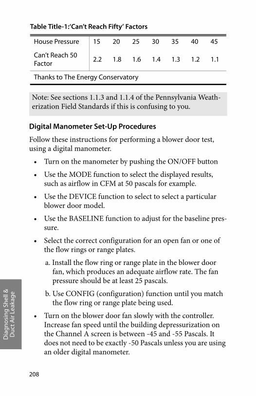
Dia
gnos
ing
Shel
l &D
uct A
ir Le
akag
e
208
Digital Manometer Set-Up Procedures
Follow these instructions for performing a blower door test, using a digital manometer.
• Turn on the manometer by pushing the ON/OFF button
• Use the MODE function to select the displayed results, such as airflow in CFM at 50 pascals for example.
• Use the DEVICE function to select to select a particular blower door model.
• Use the BASELINE function to adjust for the baseline pres-sure.
• Select the correct configuration for an open fan or one of the flow rings or range plates.
a. Install the flow ring or range plate in the blower door fan, which produces an adequate airflow rate. The fan pressure should be at least 25 pascals.
b. Use CONFIG (configuration) function until you match the flow ring or range plate being used.
• Turn on the blower door fan slowly with the controller. Increase fan speed until the building depressurization on the Channel A screen is between -45 and -55 Pascals. It does not need to be exactly -50 Pascals unless you are using an older digital manometer.
Table Title-1:‘Can’t Reach Fifty’ Factors
House Pressure 15 20 25 30 35 40 45
Can’t Reach 50 Factor
2.2 1.8 1.6 1.4 1.3 1.2 1.1
Thanks to The Energy Conservatory
Note: See sections 1.1.3 and 1.1.4 of the Pennsylvania Weath-erization Field Standards if this is confusing to you.
Dia
gnos
ing
Shel
l &D
uct A
ir Le
akag
e
Weatherization Field Guide for Pennsylvania 209
• The screen displays the CFM50 leakage of the building. If this number is fluctuating a lot, select the TIME AVERAGE function to increase the time-averaging duration. Increas-ing the time-averaging duration dampens the wind’s effect on the reading.
Blower Door Test Follow-Up
Be sure to return the house to its original condition after com-pleting the blower door test.
• Inspect combustion appliance pilot lights to ensure that blower door testing did not extinguish them.
• Reset thermostats of heaters and water heaters that were turned down for testing.
• Remove any temporary plugs that were installed to increase house pressure.
Document any unusual conditions affecting the blower door test and location where the blower door was installed.
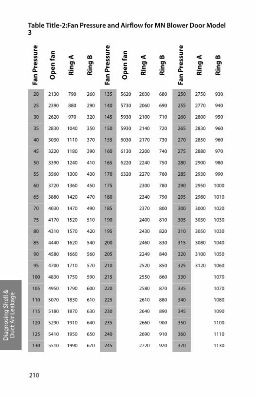
Dia
gnos
ing
Shel
l &D
uct A
ir Le
akag
e
210
Table Title-2:Fan Pressure and Airflow for MN Blower Door Model 3
Fan
Pre
ssu
re
Op
en fa
n
Rin
g A
Rin
g B
Fan
Pre
ssu
re
Op
en fa
n
Rin
g A
Rin
g B
Fan
Pre
ssu
re
Rin
g A
Rin
g B
20 2130 790 260 135 5620 2030 680 250 2750 930
25 2390 880 290 140 5730 2060 690 255 2770 940
30 2620 970 320 145 5930 2100 710 260 2800 950
35 2830 1040 350 150 5930 2140 720 265 2830 960
40 3030 1110 370 155 6030 2170 730 270 2850 960
45 3220 1180 390 160 6130 2200 740 275 2880 970
50 3390 1240 410 165 6220 2240 750 280 2900 980
55 3560 1300 430 170 6320 2270 760 285 2930 990
60 3720 1360 450 175 2300 780 290 2950 1000
65 3880 1420 470 180 2340 790 295 2980 1010
70 4030 1470 490 185 2370 800 300 3000 1020
75 4170 1520 510 190 2400 810 305 3030 1030
80 4310 1570 420 195 2430 820 310 3050 1030
85 4440 1620 540 200 2460 830 315 3080 1040
90 4580 1660 560 205 2249 840 320 3100 1050
95 4700 1710 570 210 2520 850 325 3120 1060
100 4830 1750 590 215 2550 860 330 1070
105 4950 1790 600 220 2580 870 335 1070
110 5070 1830 610 225 2610 880 340 1080
115 5180 1870 630 230 2640 890 345 1090
120 5290 1910 640 235 2660 900 350 1100
125 5410 1950 650 240 2690 910 360 1110
130 5510 1990 670 245 2720 920 370 1130
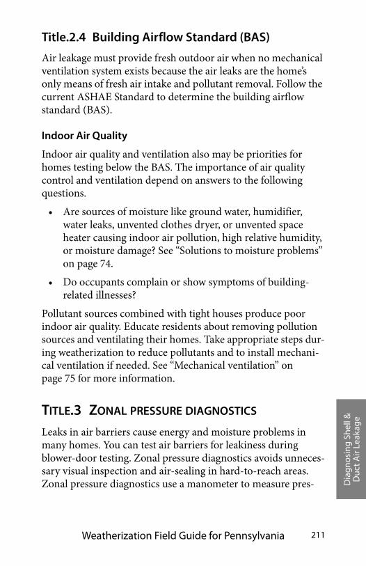
Dia
gnos
ing
Shel
l &D
uct A
ir Le
akag
e
Weatherization Field Guide for Pennsylvania 211
Title.2.4 Building Airflow Standard (BAS)
Air leakage must provide fresh outdoor air when no mechanical ventilation system exists because the air leaks are the home’s only means of fresh air intake and pollutant removal. Follow the current ASHAE Standard to determine the building airflow standard (BAS).
Indoor Air Quality
Indoor air quality and ventilation also may be priorities for homes testing below the BAS. The importance of air quality control and ventilation depend on answers to the following questions.
• Are sources of moisture like ground water, humidifier, water leaks, unvented clothes dryer, or unvented space heater causing indoor air pollution, high relative humidity, or moisture damage? See “Solutions to moisture problems” on page 74.
• Do occupants complain or show symptoms of building-related illnesses?
Pollutant sources combined with tight houses produce poor indoor air quality. Educate residents about removing pollution sources and ventilating their homes. Take appropriate steps dur-ing weatherization to reduce pollutants and to install mechani-cal ventilation if needed. See “Mechanical ventilation” on page 75 for more information.
TITLE.3 ZONAL PRESSURE DIAGNOSTICS
Leaks in air barriers cause energy and moisture problems in many homes. You can test air barriers for leakiness during blower-door testing. Zonal pressure diagnostics avoids unneces-sary visual inspection and air-sealing in hard-to-reach areas. Zonal pressure diagnostics use a manometer to measure pres-

Dia
gnos
ing
Shel
l &D
uct A
ir Le
akag
e
212
sure differences between zones in order to estimate air leakage between zones. Specifically air-barrier leak-testing can:
• Evaluate the airtightness of portions of a building’s air bar-rier—especially floors and ceilings.
• Decide which of two possible air barriers to air seal—for example, the floor versus foundation walls.
• Estimate the air leakage in CFM50 through a particular air barrier, for the purpose of estimating the effort and cost necessary to seal the leaks.
• Determine whether building cavities like floor cavities, porch roofs, and overhangs are conduits for air leakage.
• Determine whether building cavities, intermediate zones, and ducts are connected by air leaks.
Zonal pressure diagnostics provides a range of information from simple clues about which parts of a building are leakiest, to spe-
2.
BA
A B
house WRT outdoors
-50
Blower door test: Zonal pressure diagnostics involves a series of techniques, applied during a blower-door test, with the house at a negative pressure of 50 pascals with reference to outdoors. If CFM50 cannot be achieved, go to the next lowest even number using half of that as the relative connection determining point. This house has 3000 CFM50 of air leakage. Testing air barriers can help determine where that leakage is coming from.
2.
BA
A B
3000
Dia
gnos
ing
Shel
l &D
uct A
ir Le
akag
e
Weatherization Field Guide for Pennsylvania 213
cific estimates of the airflow and hole size through a particular air barrier like a ceiling.
When you’re planning to identify and improve a home’s air bar-rier, consider the leakage characteristics of the building compo-nents. Creating an effective air barrier in an existing home involves choosing existing building components to act as air barriers and then air-sealing their border regions. Chances are that you’ll find two or more of these components adjacent to one another so that they combine to form a better air barrier compared to being considered alone. The classification below includes only the component itself, not seams and border areas where it meets other components.
Title.3.1 Primary versus secondary air barriers
The air barrier should be a material that is continuous, sealed at seams, and is itself relatively impermeable to airflow. Where there are two possible air barriers, the most airtight air barrier is the primary air barrier and the least airtight is the secondary air barrier. The primary air barrier should be adjacent to the insula-tion to ensure the insulation’s effectiveness. Therefore, testing is important to verify that insulation and primary air barrier are together. Sometimes we’re surprised during testing to find that our assumed primary air barrier is actually secondary, and the secondary air barrier is actually primary. For example, the roof may be the primary air barrier instead of the top-floor ceiling as assumed.
Intermediate zones are unconditioned spaces, sheltered within the exterior shell of the house. Intermediate zones can be included inside the home’s primary air barrier or outside it. Intermediate zones include: unheated basements, crawl spaces, attics, enclosed porches, and attached garages. Intermediate zones have two potential air barriers: one between the zone and house and one between the zone and outdoors. For example, an attic or roof space has two air barriers: the ceiling and roof.
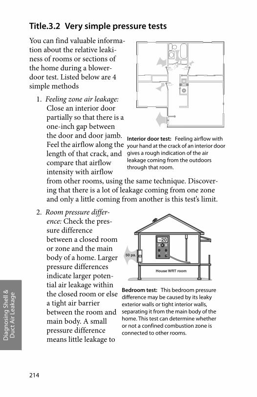
Dia
gnos
ing
Shel
l &D
uct A
ir Le
akag
e
214
Title.3.2 Very simple pressure tests
You can find valuable informa-tion about the relative leaki-ness of rooms or sections of the home during a blower-door test. Listed below are 4 simple methods
1. Feeling zone air leakage: Close an interior door partially so that there is a one-inch gap between the door and door jamb. Feel the airflow along the length of that crack, and compare that airflow intensity with airflow from other rooms, using the same technique. Discover-ing that there is a lot of leakage coming from one zone and only a little coming from another is this test’s limit.
2. Room pressure differ-ence: Check the pres-sure difference between a closed room or zone and the main body of a home. Larger pressure differences indicate larger poten-tial air leakage within the closed room or else a tight air barrier between the room and main body. A small pressure difference means little leakage to
�� ���
Interior door test: Feeling airflow with your hand at the crack of an interior door gives a rough indication of the air leakage coming from the outdoors through that room.
BA
A B
–20
50 pa.
House WRT room
Bedroom test: This bedroom pressure difference may be caused by its leaky exterior walls or tight interior walls, separating it from the main body of the home. This test can determine whether or not a confined combustion zone is connected to other rooms.
Dia
gnos
ing
Shel
l &D
uct A
ir Le
akag
e
Weatherization Field Guide for Pennsylvania 215
the outdoors through the room or a leaky air barrier between the house and room.
3. Observing the ceiling/attic floor: Depressurize the home to 50 pascals and observe the top-floor ceiling from the attic with a good flashlight. Air leaks will show in movement of loose fill insulation, blowing dust, moving cobwebs, etc.
4. Observing smoke movement: Depressurize the home to 50 pascals and observe the movement of smoke through the house and out of its air leaks.
Tests 1, 3, and 4 are important observations. Feeling airflow with your hand or observing smoke are mere observations and are good client education opportunities. These simple techniques have helped identify many air leaks that could otherwise have remained hidden. Closing doors to leakier rooms will usually produce a greater reduction in CFM50 than closing doors to tighter ones.
Air leakage, restricted by closing a door, may have alternative indoor paths rendering test 2 inaccurate. Only practice and experience can guide your decisions about the applicability and usefulness of these tests.
Title.3.3 Using a manometer to test air barriers
A manometer pressure gauge, used for blower door testing, also can measure pressures between the house and its intermediate zones during blower door tests.
The blower door, when used to create a house-to-outdoors pres-sure of –50 pascals, also creates house-to-zone pressures of between 0 and –50 pascals in the home’s intermediate zones. The amount of depressurization depends on the relative leaki-ness of the zone’s two air barriers.
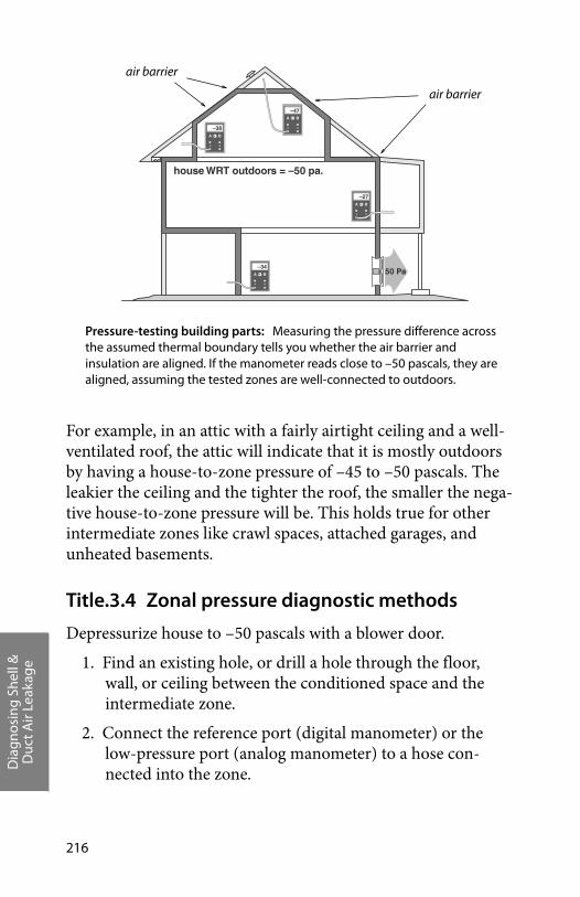
Dia
gnos
ing
Shel
l &D
uct A
ir Le
akag
e
216
For example, in an attic with a fairly airtight ceiling and a well-ventilated roof, the attic will indicate that it is mostly outdoors by having a house-to-zone pressure of –45 to –50 pascals. The leakier the ceiling and the tighter the roof, the smaller the nega-tive house-to-zone pressure will be. This holds true for other intermediate zones like crawl spaces, attached garages, and unheated basements.
Title.3.4 Zonal pressure diagnostic methods
Depressurize house to –50 pascals with a blower door.
1. Find an existing hole, or drill a hole through the floor, wall, or ceiling between the conditioned space and the intermediate zone.
2. Connect the reference port (digital manometer) or the low-pressure port (analog manometer) to a hose con-nected into the zone.
house WRT outdoors = –50 pa.
BA
A B
–27
BA
A B
–34
BA
A B
–38
BA
A B
–47
50 Pa
Pressure-testing building parts: Measuring the pressure difference across the assumed thermal boundary tells you whether the air barrier and insulation are aligned. If the manometer reads close to –50 pascals, they are aligned, assuming the tested zones are well-connected to outdoors.
air barrier
air barrier
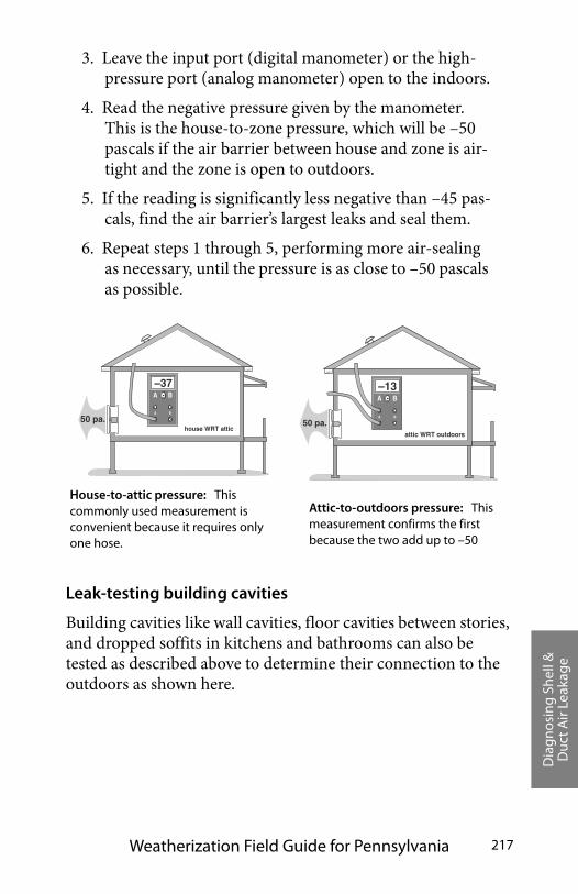
Dia
gnos
ing
Shel
l &D
uct A
ir Le
akag
e
Weatherization Field Guide for Pennsylvania 217
3. Leave the input port (digital manometer) or the high-pressure port (analog manometer) open to the indoors.
4. Read the negative pressure given by the manometer. This is the house-to-zone pressure, which will be –50 pascals if the air barrier between house and zone is air-tight and the zone is open to outdoors.
5. If the reading is significantly less negative than –45 pas-cals, find the air barrier’s largest leaks and seal them.
6. Repeat steps 1 through 5, performing more air-sealing as necessary, until the pressure is as close to –50 pascals as possible.
Leak-testing building cavities
Building cavities like wall cavities, floor cavities between stories, and dropped soffits in kitchens and bathrooms can also be tested as described above to determine their connection to the outdoors as shown here.
B A
A B
attic WRT outdoors
–13
50 pa .
B A
A B
–37
house WRT attic 50 pa.
House-to-attic pressure: This commonly used measurement is convenient because it requires only one hose.
Attic-to-outdoors pressure: This measurement confirms the first because the two add up to –50
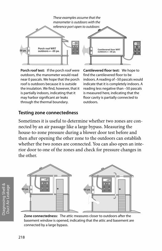
Dia
gnos
ing
Shel
l &D
uct A
ir Le
akag
e
218
Testing zone connectedness
Sometimes it is useful to determine whether two zones are con-nected by an air passage like a large bypass. Measuring the house-to-zone pressure during a blower door test before and then after opening the other zone to the outdoors can establish whether the two zones are connected. You can also open an inte-rior door to one of the zones and check for pressure changes in the other.
B A
A B
–20
Po rc h r oof WR T outdoor s = –20 pa. 50 pa.
B A
A B
–30
Cantile vered floor WR T outdoor s = –30 pa.
Cantilevered floor test: We hope to find the cantilevered floor to be indoors. A reading of –50 pascals would indicate that it is completely indoors. A reading less negative than –50 pascals is measured here, indicating that the floor cavity is partially connected to outdoors.
Porch roof test: If the porch roof were outdoors, the manometer would read near 0 pascals. We hope that the porch roof is outdoors because it is outside the insulation. We find, however, that it is partially indoors, indicating that it may harbor significant air leaks through the thermal boundary.
These examples assume that the manometer is outdoors with the reference port open to outdoors
Zone connectedness: The attic measures closer to outdoors after the basement window is opened, indicating that the attic and basement are connected by a large bypass.
3.
BA
A B50 pa.
–41
3.
BA
A B50 pa.
–47

Dia
gnos
ing
Shel
l &D
uct A
ir Le
akag
e
Weatherization Field Guide for Pennsylvania 219
Title.3.5 Zone pressures, air sealing, and insulation
Zone pressures are one of several factors used to determine where the thermal boundary should be. Where to air-seal and where to insulate are necessary retrofit decisions. When there are two choices of where to insulate and air-seal, zone pressures along with other considerations help you decide.
Including the heating ducts within the thermal boundary is often preferred because this option reduces energy waste from duct leakage. The location of ducts either within or outside the thermal boundary is an important factor in determining the cost-effectiveness of duct sealing and insulation.
If a floor is already insulated, it makes sense to establish the air barrier there. If the foundation wall is more airtight than the floor, that would be one reason to insulate the foundation wall.
For zonal pressure diagnostics, the house-to-zone pressure is often used to determine which of two air barriers is tighter, for example.
• Readings of negative 25-to-50 pascals house-to-attic pres-sure mean that the ceiling is tighter than the roof. If the roof is quite airtight, achieving a 50-pascal house-to-attic pressure difference may be difficult. However if the roof is well-ventilated, achieving a near-50-pascal difference should be possible.
• Readings of 0 to –25 pascals house-to-attic pressure mean that the roof is tighter than the ceiling. If the roof is well-ventilated, the ceiling has even more leak area than the roof ’s vent area.
• Readings around –25 pascals house-to-attic pressure indi-cate that the roof and ceiling are equally airtight or leaky.
You can use the leakage characteristics you observe in one air barrier to estimate leakage through another. The area of attic or crawl-space vents is a valuable piece of information. The relative airtightness of a building component is another.
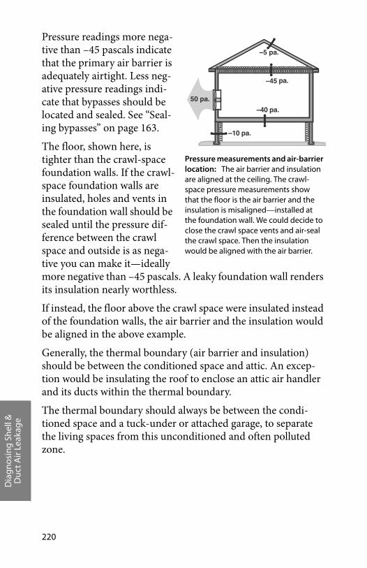
Dia
gnos
ing
Shel
l &D
uct A
ir Le
akag
e
220
Pressure readings more nega-tive than –45 pascals indicate that the primary air barrier is adequately airtight. Less neg-ative pressure readings indi-cate that bypasses should be located and sealed. See “Seal-ing bypasses” on page 163.
The floor, shown here, is tighter than the crawl-space foundation walls. If the crawl-space foundation walls are insulated, holes and vents in the foundation wall should be sealed until the pressure dif-ference between the crawl space and outside is as nega-tive you can make it—ideally more negative than –45 pascals. A leaky foundation wall renders its insulation nearly worthless.
If instead, the floor above the crawl space were insulated instead of the foundation walls, the air barrier and the insulation would be aligned in the above example.
Generally, the thermal boundary (air barrier and insulation) should be between the conditioned space and attic. An excep-tion would be insulating the roof to enclose an attic air handler and its ducts within the thermal boundary.
The thermal boundary should always be between the condi-tioned space and a tuck-under or attached garage, to separate the living spaces from this unconditioned and often polluted zone.
–5 pa.
–45 pa.
–40 pa.
–10 pa.
50 pa.
Pressure measurements and air-barrier location: The air barrier and insulation are aligned at the ceiling. The crawl-space pressure measurements show that the floor is the air barrier and the insulation is misaligned—installed at the foundation wall. We could decide to close the crawl space vents and air-seal the crawl space. Then the insulation would be aligned with the air barrier.
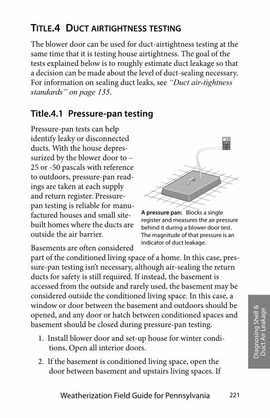
Dia
gnos
ing
Shel
l &D
uct A
ir Le
akag
e
Weatherization Field Guide for Pennsylvania 221
TITLE.4 DUCT AIRTIGHTNESS TESTING
The blower door can be used for duct-airtightness testing at the same time that it is testing house airtightness. The goal of the tests explained below is to roughly estimate duct leakage so that a decision can be made about the level of duct-sealing necessary. For information on sealing duct leaks, see “Duct air-tightness standards” on page 135.
Title.4.1 Pressure-pan testing
Pressure-pan tests can help identify leaky or disconnected ducts. With the house depres-surized by the blower door to –25 or -50 pascals with reference to outdoors, pressure-pan read-ings are taken at each supply and return register. Pressure-pan testing is reliable for manu-factured houses and small site-built homes where the ducts are outside the air barrier.
Basements are often considered part of the conditioned living space of a home. In this case, pres-sure-pan testing isn’t necessary, although air-sealing the return ducts for safety is still required. If instead, the basement is accessed from the outside and rarely used, the basement may be considered outside the conditioned living space. In this case, a window or door between the basement and outdoors should be opened, and any door or hatch between conditioned spaces and basement should be closed during pressure-pan testing.
1. Install blower door and set-up house for winter condi-tions. Open all interior doors.
2. If the basement is conditioned living space, open the door between basement and upstairs living spaces. If
BA
A B
4.0
A pressure pan: Blocks a single register and measures the air pressure behind it during a blower door test. The magnitude of that pressure is an indicator of duct leakage.

Dia
gnos
ing
Shel
l &D
uct A
ir Le
akag
e
222
the basement is considered outside the conditioned liv-ing space, close the door between basement and upstairs living spaces and open a basement window.
3. Turn furnace off. Ensure that all grilles, registers, and dampers are fully open.
4. Temporarily seal any outside fresh-air intakes to the duct system. Seal all registers that are in unconditioned living spaces (supply registers in unconditioned base-ments, for example).
5. Open attics, crawl spaces, and garages as much as possi-ble to the outside.
6. Connect hose between pressure pan and the input tap on the digital manometer. Leave the reference tap open.
7. With the blower door at –25 pascals, place the pressure pan completely over a grille or register to form a tight seal. Record the reading.
8. If a grille is too large or a supply register is difficult to access (under a kitchen cabinet, for example), seal the grille or register with masking tape. Insert a pressure probe through the masking tape and record the read-ing.
9. Repeat this test for each register and grille in a system-atic fashion.
Pressure-pan duct standards
If the ducts are perfectly sealed with no leakage to the outside, no pressure difference (0.0 pascals) will be measured during a pressure-pan test. The higher the measured pressure-pan read-ing, the more connected the duct is to the outdoors. Readings greater than 1.0 pascal require investigation and sealing of leaks causing the reading.
Pay particular attention to registers connected to ducts that are located in areas outside the conditioned living space. These
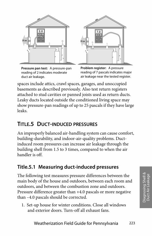
Dia
gnos
ing
Shel
l &D
uct A
ir Le
akag
e
Weatherization Field Guide for Pennsylvania 223
spaces include attics, crawl spaces, garages, and unoccupied basements as described previously. Also test return registers attached to stud cavities or panned joists used as return ducts. Leaky ducts located outside the conditioned living space may show pressure-pan readings of up to 25 pascals if they have large leaks.
TITLE.5 DUCT-INDUCED PRESSURES
An improperly balanced air-handling system can cause comfort, building-durability, and indoor-air-quality problems. Duct-induced room pressures can increase air leakage through the building shell from 1.5 to 3 times, compared to when the air handler is off.
Title.5.1 Measuring duct-induced pressures
The following test measures pressure differences between the main body of the house and outdoors, between each room and outdoors, and between the combustion zone and outdoors. Pressure difference greater than +4.0 pascals or more negative than –4.0 pascals should be corrected.
1. Set-up house for winter conditions. Close all windows and exterior doors. Turn-off all exhaust fans.
Pressure pan test: A pressure-pan reading of 2 indicates moderate duct air leakage.
Problem register: A pressure reading of 7 pascals indicates major air leakage near the tested register.
BA
A B
25 pa.
2.0BA
A B
25 pa.
7.0
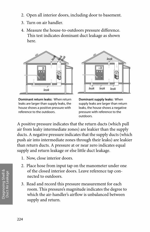
Dia
gnos
ing
Shel
l &D
uct A
ir Le
akag
e
224
2. Open all interior doors, including door to basement.
3. Turn on air handler.
4. Measure the house-to-outdoors pressure difference. This test indicates dominant duct leakage as shown here.
A positive pressure indicates that the return ducts (which pull air from leaky intermediate zones) are leakier than the supply ducts. A negative pressure indicates that the supply ducts (which push air into intermediate zones through their leaks) are leakier than return ducts. A pressure at or near zero indicates equal supply and return leakage or else little duct leakage.
1. Now, close interior doors.
2. Place hose from input tap on the manometer under one of the closed interior doors. Leave reference tap con-nected to outdoors.
3. Read and record this pressure measurement for each room. This pressure’s magnitude indicates the degree to which the air-handler’s airflow is unbalanced between supply and return.
BA
A B
2BA
A B
–3
Dominant return leaks: When return leaks are larger than supply leaks, the house shows a positive pressure with reference to the outdoors.
Dominant supply leaks: When supply leaks are larger than return leaks, the house shows a negative pressure with reference to the outdoors.
leak
leak leak leakleak
leak
leak
leak

Dia
gnos
ing
Shel
l &D
uct A
ir Le
akag
e
Weatherization Field Guide for Pennsylvania 225
If pressure difference is more than ± 4.0 pascals with the air handler operating, pressure relief is neces-sary. To estimate the amount of pressure relief, slowly open door until pressure difference drops to between +4.0 pascals and –4.0 pascals Estimate area of open door. This is the area required to provide pressure relief. Pressure relief may include undercutting the door or installing transfer grilles.
For information on the danger of depressurized combustion zones, see “CAZ Combustion Safety Test” on page 103. For informa-tion on reducing duct-induced room pressures, see “Duct improvements to increase airflow and improve comfort” on page 141. For information on sealing duct leaks, see “Duct air-tightness standards” on page 135.
��
� �
�
Blocked return path: With interior doors closed, the large positive pressure in the bedroom is caused by the lack of a air return register in the bedroom. The airflow in this forced-air system is unbalanced, creating this pressure, and forcing room air through the room’s air leaks.

Dia
gnos
ing
Shel
l &D
uct A
ir Le
akag
e
226
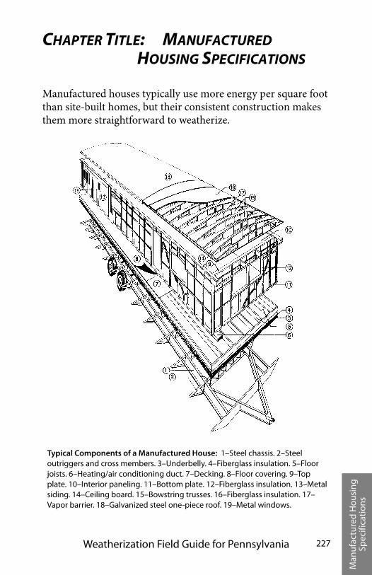
Man
ufac
ture
d H
ousi
ng
Spec
ifica
tion
s
Weatherization Field Guide for Pennsylvania 227
CHAPTER TITLE: MANUFACTURED HOUSING SPECIFICATIONS
Manufactured houses typically use more energy per square foot than site-built homes, but their consistent construction makes them more straightforward to weatherize.
Typical Components of a Manufactured House: 1–Steel chassis. 2–Steel outriggers and cross members. 3–Underbelly. 4–Fiberglass insulation. 5–Floor joists. 6–Heating/air conditioning duct. 7–Decking. 8–Floor covering. 9–Top plate. 10–Interior paneling. 11–Bottom plate. 12–Fiberglass insulation. 13–Metal siding. 14–Ceiling board. 15–Bowstring trusses. 16–Fiberglass insulation. 17–Vapor barrier. 18–Galvanized steel one-piece roof. 19–Metal windows.
Man
ufac
ture
d H
ousi
ng
Spec
ifica
tion
s
228
Insulation upgrades save the most energy in manufactured houses, though sealing shell and duct air leaks presents good opportunities, too. Manufactured house heating retrofit and replacement are often cost-effective when a customer’s energy usage is high. See “PA WAP Manufactured Home, Measure Selection Priority List (MHEA)” on page 19.
TITLE.1 MANUFACTURED HOUSE HEATING
Manufactured house furnaces are different from conventional furnaces in the following ways:
• A great majority of manufactured houses are equipped with downflow furnaces, designed specifically for manufactured houses.
• Manufactured house combustion furnaces are sealed-com-bustion units that use outdoor combustion air, unlike most furnaces in site-built homes. They don’t have draft diverters or barometric draft controls.
• Manufactured house furnaces require an outdoor source of combustion air.
• Manufactured house furnaces have either a manufactured chimney that includes a passageway for combustion air or a combustion-air chute connecting the burner with the crawl space.
• Gas-fired furnaces have kits attached, containing alterna-tive orifices, to burn either propane or gas.
• Return air is supplied to the furnace through a large open-ing in the furnace cabinet, rather than through ducts con-nected to the blower compartment.
Manufactured house furnaces have been sealed-combustion since the early 1970s. Gas furnaces are either the old atmo-spheric sealed-combustion type or the newer fan-assisted mid-efficiency type. Some older sealed-combustion furnaces had
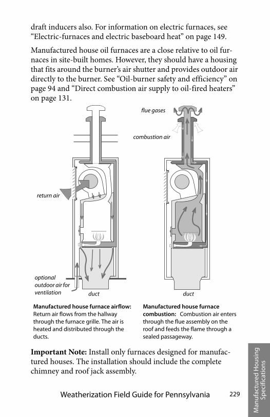
Man
ufac
ture
d H
ousi
ng
Spec
ifica
tion
s
Weatherization Field Guide for Pennsylvania 229
draft inducers also. For information on electric furnaces, see “Electric-furnaces and electric baseboard heat” on page 149.
Manufactured house oil furnaces are a close relative to oil fur-naces in site-built homes. However, they should have a housing that fits around the burner’s air shutter and provides outdoor air directly to the burner. See “Oil-burner safety and efficiency” on page 94 and “Direct combustion air supply to oil-fired heaters” on page 131.
Important Note: Install only furnaces designed for manufac-tured houses. The installation should include the complete chimney and roof jack assembly.
Manufactured house furnace airflow: Return air flows from the hallway through the furnace grille. The air is heated and distributed through the ducts.
return air
combustion air
flue gases
Manufactured house furnace combustion: Combustion air enters through the flue assembly on the roof and feeds the flame through a sealed passageway.
optional outdoor air for ventilation duct duct
Man
ufac
ture
d H
ousi
ng
Spec
ifica
tion
s
230
Title.1.1 Furnace maintenance and energy efficiency
Manufactured house furnaces should comply with this guide-book’s combustion safety and efficiency standards. See “Gas burner safety and efficiency testing” on page 88 and “Oil-burner safety and efficiency” on page 94.
Title.1.2 Heating appliance replacement
Manufactured house furnaces must be replaced by furnaces designed and listed for use in manufactured houses. If a heat exchanger is available to replace the existing cracked heat exchanger, consider heat-exchanger replacement as a repair pri-ority instead of replacing the furnace.
Consider replacing the existing furnace with a sealed-combus-tion, downflow, condensing furnace. Manufacturers make con-densing furnaces, approved for manufactured houses. In any case replacement furnaces must fall within the specifications for HUD and Pennsylvania Combustion Efficiency Standards.
Manufactured house furnaces may be replaced when any of the following 3 conditions is observed.
1. The furnace has a cracked heat exchanger.
2. Repair and retrofit exceed half of the replacement cost.
3. The furnace is not operating and not repairable.
Follow these procedures when installing new manufactured house furnaces.
Install a new furnace base.
Attach the furnace base firmly to the duct, and seal all seams between the base and duct with mastic and fabric tape before installing the furnace.
Support the main duct underneath the furnace with addi-tional strapping if necessary.
Man
ufac
ture
d H
ousi
ng
Spec
ifica
tion
s
Weatherization Field Guide for Pennsylvania 231
When replacing manufactured house furnaces, note the differences between old furnace and new, in the way each supplies itself with combustion air.
Install a new chimney that is manufactured specifically for the new furnace. Install to manufacturer's specifications.
Manufactured house furnaces have short chimneys, and their combustion process depends on a delicate balance between combustion air entering and combustion gases leaving. The fur-nace demands a vertical, leak-free chimney, and a properly installed chimney cap. Follow manufacturer’s installation instructions exactly.
TITLE.2 MANUFACTURED HOUSE AIR SEALING
The locations and relative importance of air-leakage sites was a mystery before blower doors. Some manufactured houses are fairly airtight and some are incredibly leaky. It’s recommended that a blower door be used to guide air-sealing work and to check Building Airflow Standard in manufactured houses.
Title.2.1 Air-leakage locations
The following locations have been identified by technicians using blower doors as the most serious air-leakage sites. Win-dow and door air leakage is more of a comfort problem than a serious energy problem.
• Plumbing penetrations in floors, walls, and ceilings. Water-heater closets with exterior doors are particularly serious air-leakage problems, having large openings into the bath-room and other areas.
• Torn or missing underbelly, exposing flaws in the floor to the ventilated crawl space.
• Large gaps around furnace and water heater chimneys. A large gap around the furnace chimney jack, combined with inadequate return air, can cause the blower fan to depres-
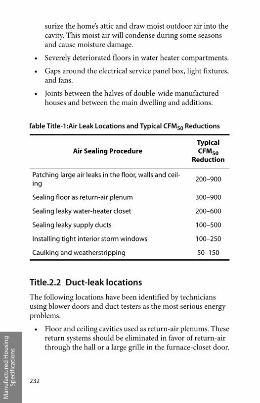
Man
ufac
ture
d H
ousi
ng
Spec
ifica
tion
s
232
surize the home’s attic and draw moist outdoor air into the cavity. This moist air will condense during some seasons and cause moisture damage.
• Severely deteriorated floors in water heater compartments.
• Gaps around the electrical service panel box, light fixtures, and fans.
• Joints between the halves of double-wide manufactured houses and between the main dwelling and additions.
Title.2.2 Duct-leak locations
The following locations have been identified by technicians using blower doors and duct testers as the most serious energy problems.
• Floor and ceiling cavities used as return-air plenums. These return systems should be eliminated in favor of return-air through the hall or a large grille in the furnace-closet door.
Table Title-1:Air Leak Locations and Typical CFM50 Reductions
Air Sealing ProcedureTypical CFM50
Reduction
Patching large air leaks in the floor, walls and ceil-ing
200–900
Sealing floor as return-air plenum 300–900
Sealing leaky water-heater closet 200–600
Sealing leaky supply ducts 100–500
Installing tight interior storm windows 100–250
Caulking and weatherstripping 50–150
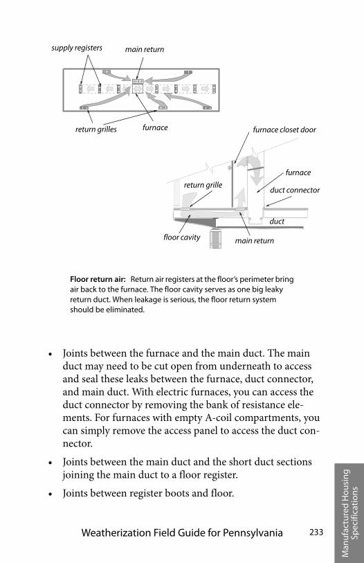
Man
ufac
ture
d H
ousi
ng
Spec
ifica
tion
s
Weatherization Field Guide for Pennsylvania 233
• Joints between the furnace and the main duct. The main duct may need to be cut open from underneath to access and seal these leaks between the furnace, duct connector, and main duct. With electric furnaces, you can access the duct connector by removing the bank of resistance ele-ments. For furnaces with empty A-coil compartments, you can simply remove the access panel to access the duct con-nector.
• Joints between the main duct and the short duct sections joining the main duct to a floor register.
• Joints between register boots and floor.
furnace
duct
return grille
floor cavity
duct connector
furnace closet door
main return
return grilles furnace
supply registers main return
Floor return air: Return air registers at the floor’s perimeter bring air back to the furnace. The floor cavity serves as one big leaky return duct. When leakage is serious, the floor return system should be eliminated.
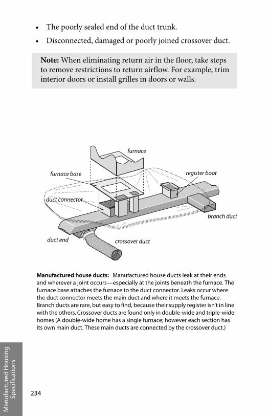
Man
ufac
ture
d H
ousi
ng
Spec
ifica
tion
s
234
• The poorly sealed end of the duct trunk.
• Disconnected, damaged or poorly joined crossover duct.
Note: When eliminating return air in the floor, take steps to remove restrictions to return airflow. For example, trim interior doors or install grilles in doors or walls.
Manufactured house ducts: Manufactured house ducts leak at their ends and wherever a joint occurs—especially at the joints beneath the furnace. The furnace base attaches the furnace to the duct connector. Leaks occur where the duct connector meets the main duct and where it meets the furnace. Branch ducts are rare, but easy to find, because their supply register isn’t in line with the others. Crossover ducts are found only in double-wide and triple-wide homes (A double-wide home has a single furnace; however each section has its own main duct. These main ducts are connected by the crossover duct.)
furnace
register boot
branch duct
crossover ductduct end
duct connector
furnace base
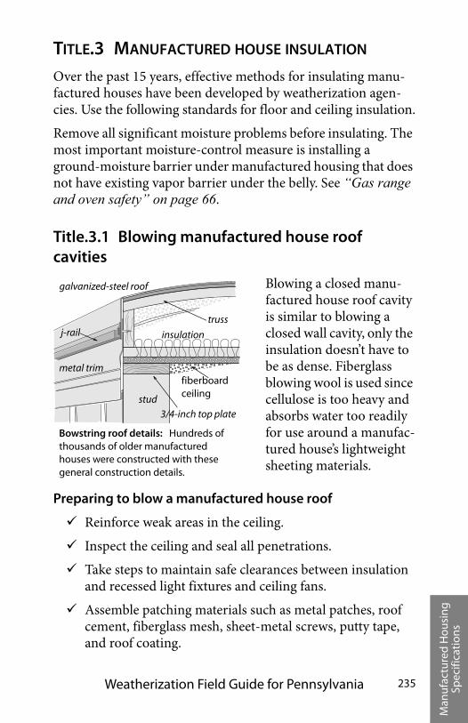
Man
ufac
ture
d H
ousi
ng
Spec
ifica
tion
s
Weatherization Field Guide for Pennsylvania 235
TITLE.3 MANUFACTURED HOUSE INSULATION
Over the past 15 years, effective methods for insulating manu-factured houses have been developed by weatherization agen-cies. Use the following standards for floor and ceiling insulation.
Remove all significant moisture problems before insulating. The most important moisture-control measure is installing a ground-moisture barrier under manufactured housing that does not have existing vapor barrier under the belly. See “Gas range and oven safety” on page 66.
Title.3.1 Blowing manufactured house roof cavities
Blowing a closed manu-factured house roof cavity is similar to blowing a closed wall cavity, only the insulation doesn’t have to be as dense. Fiberglass blowing wool is used since cellulose is too heavy and absorbs water too readily for use around a manufac-tured house’s lightweight sheeting materials.
Preparing to blow a manufactured house roof
Reinforce weak areas in the ceiling.
Inspect the ceiling and seal all penetrations.
Take steps to maintain safe clearances between insulation and recessed light fixtures and ceiling fans.
Assemble patching materials such as metal patches, roof cement, fiberglass mesh, sheet-metal screws, putty tape, and roof coating.
Bowstring roof details: Hundreds of thousands of older manufactured houses were constructed with these general construction details.
stud
galvanized-steel roof
j-rail
metal trim
insulation
truss
3/4-inch top plate
fiberboard ceiling
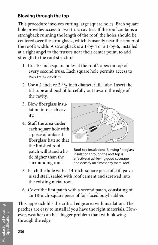
Man
ufac
ture
d H
ousi
ng
Spec
ifica
tion
s
236
Blowing through the top
This procedure involves cutting large square holes. Each square hole provides access to two truss cavities. If the roof contains a strongback running the length of the roof, the holes should be centered over the strongback, which is usually near the center of the roof ’s width. A strongback is a 1-by-4 or a 1-by-6, installed at a right angel to the trusses near their center point, to add strength to the roof structure.
1. Cut 10-inch square holes at the roof ’s apex on top of every second truss. Each square hole permits access to two truss cavities.
2. Use a 2-inch or 2-1/2-inch diameter fill-tube. Insert the fill-tube and push it forcefully out toward the edge of the cavity.
3. Blow fiberglass insu-lation into each cav-ity.
4. Stuff the area under each square hole with a piece of unfaced fiberglass batt so that the finished roof patch will stand a lit-tle higher than the surrounding roof.
5. Patch the hole with a 14-inch-square piece of stiff galva-nized steel, sealed with roof cement and screwed into the existing metal roof.
6. Cover the first patch with a second patch, consisting of an 18-inch-square piece of foil-faced butyl rubber.
This approach fills the critical edge area with insulation. The patches are easy to install if you have the right materials. How-ever, weather can be a bigger problem than with blowing through the edge.
Roof-top insulation: Blowing fiberglass insulation through the roof top is effective at achieving good coverage and density on almost any metal roof.
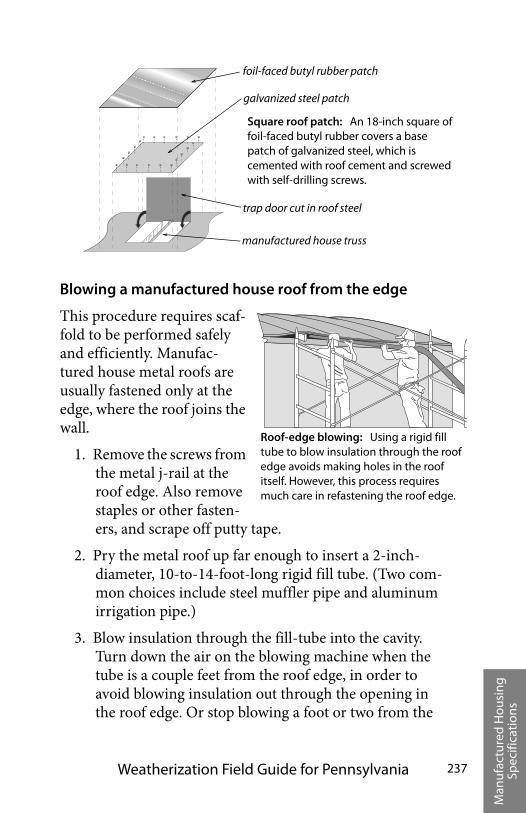
Man
ufac
ture
d H
ousi
ng
Spec
ifica
tion
s
Weatherization Field Guide for Pennsylvania 237
Blowing a manufactured house roof from the edge
This procedure requires scaf-fold to be performed safely and efficiently. Manufac-tured house metal roofs are usually fastened only at the edge, where the roof joins the wall.
1. Remove the screws from the metal j-rail at the roof edge. Also remove staples or other fasten-ers, and scrape off putty tape.
2. Pry the metal roof up far enough to insert a 2-inch-diameter, 10-to-14-foot-long rigid fill tube. (Two com-mon choices include steel muffler pipe and aluminum irrigation pipe.)
3. Blow insulation through the fill-tube into the cavity. Turn down the air on the blowing machine when the tube is a couple feet from the roof edge, in order to avoid blowing insulation out through the opening in the roof edge. Or stop blowing a foot or two from the
Square roof patch: An 18-inch square of foil-faced butyl rubber covers a base patch of galvanized steel, which is cemented with roof cement and screwed with self-drilling screws.
foil-faced butyl rubber patch
galvanized steel patch
trap door cut in roof steel
manufactured house truss
Roof-edge blowing: Using a rigid fill tube to blow insulation through the roof edge avoids making holes in the roof itself. However, this process requires much care in refastening the roof edge.
Man
ufac
ture
d H
ousi
ng
Spec
ifica
tion
s
238
edge, and stuff the last foot or two with unfaced fiber-glass batts.
4. Fasten the roof edge back to the wall using galvanized roofing nails, a new metal j-rail, new putty tape, and larger screws. The ideal way to re-fasten the metal roof edge is with air-driven galvanized staples, which is the way most roof edges were attached originally.
Note that re-installation of the roof edge is the most important part of this procedure. Putty tape must be replaced and installed as it was originally. This usually involves installing one layer of putty tape under the metal roof and another between the metal roof edge and the j-rail.
The advantages of blowing through the edge is that if you have the right tools, including a powered stapler, this method can be very fast and doesn’t require cutting into the roof. The disadvan-tages of this procedure are that you need scaffolding and you can’t do it if the roof has a strongback.
Blowing a manufactured house roof from indoors
This procedure requires the drilling of straight rows of 3-inch or 4-inch holes and blowing insulation into the roof cavity through a fill tube.
1. Drill a 3-inch or 4-inch hole in an unseen location to discover whether the roof structure contains a strong-back that would prevent blowing the roof cavity from a single row of holes.
2. Devise a way to drill a straight row of holes down the center of the ceiling. If a strongback exists, drill two rows of holes at the quarter points of the width of the ceiling.
3. Insert a flexible plastic fill tube into the cavity, and push it as far as possible toward the edge of the roof.
4. Fill the cavity with tightly packed fiberglass insulation.

Man
ufac
ture
d H
ousi
ng
Spec
ifica
tion
s
Weatherization Field Guide for Pennsylvania 239
The obvious advantage to this method is that you are indoors, out of the weather. The disadvantages include being indoors where you can make a mess—or worse, damage something. Care must be taken not to damage the holes so that the plastic hole covers won’t fit properly.
Title.3.2 Manufactured house floor insulation
Manufactured house floor insulation is a beneficial measure for cool climates. The original insulation is usually fastened to the bottom of the floor joists, leaving the cavity uninsulated and subject to convection currents. This greatly reduces the insula-tion’s R-value.
Preparing for manufactured house floor insulation
Prior to installing floor insulation, always perform these repairs.
1. Repair plumbing leaks.
2. Tightly seal all holes in the floor.
3. Inspect and seal ducts.
4. Install a ground moisture barrier in the crawl space if possible.
Blowing bellies: A flexible fill tube, which is significantly stiffer than the blower hose, blows fiberglass insulation through a hole in the belly from underneath the home.
existing insulation
new insulation
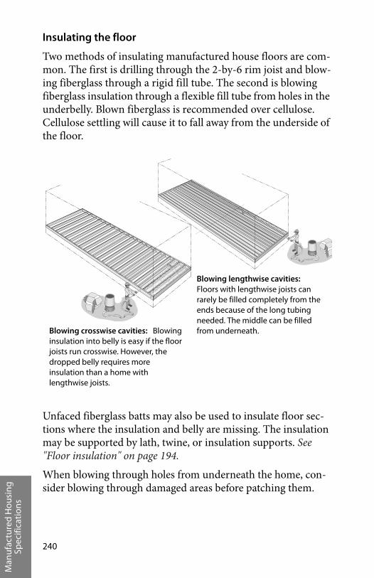
Man
ufac
ture
d H
ousi
ng
Spec
ifica
tion
s
240
Insulating the floor
Two methods of insulating manufactured house floors are com-mon. The first is drilling through the 2-by-6 rim joist and blow-ing fiberglass through a rigid fill tube. The second is blowing fiberglass insulation through a flexible fill tube from holes in the underbelly. Blown fiberglass is recommended over cellulose. Cellulose settling will cause it to fall away from the underside of the floor.
Unfaced fiberglass batts may also be used to insulate floor sec-tions where the insulation and belly are missing. The insulation may be supported by lath, twine, or insulation supports. See "Floor insulation" on page 194.
When blowing through holes from underneath the home, con-sider blowing through damaged areas before patching them.
Blowing crosswise cavities: Blowing insulation into belly is easy if the floor joists run crosswise. However, the dropped belly requires more insulation than a home with lengthwise joists.
Blowing lengthwise cavities: Floors with lengthwise joists can rarely be filled completely from the ends because of the long tubing needed. The middle can be filled from underneath.
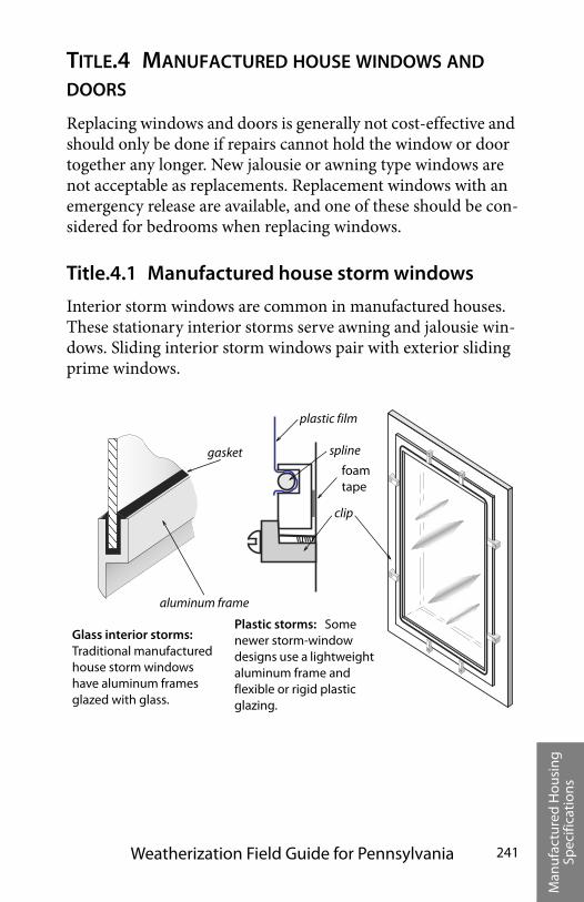
Man
ufac
ture
d H
ousi
ng
Spec
ifica
tion
s
Weatherization Field Guide for Pennsylvania 241
TITLE.4 MANUFACTURED HOUSE WINDOWS AND DOORS
Replacing windows and doors is generally not cost-effective and should only be done if repairs cannot hold the window or door together any longer. New jalousie or awning type windows are not acceptable as replacements. Replacement windows with an emergency release are available, and one of these should be con-sidered for bedrooms when replacing windows.
Title.4.1 Manufactured house storm windows
Interior storm windows are common in manufactured houses. These stationary interior storms serve awning and jalousie win-dows. Sliding interior storm windows pair with exterior sliding prime windows.
Glass interior storms: Traditional manufactured house storm windows have aluminum frames glazed with glass.
clip
gasket spline
plastic film
aluminum frame
foam tape
Plastic storms: Some newer storm-window designs use a lightweight aluminum frame and flexible or rigid plastic glazing.
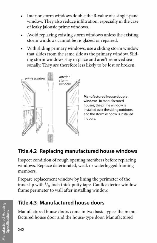
Man
ufac
ture
d H
ousi
ng
Spec
ifica
tion
s
242
• Interior storm windows double the R-value of a single-pane window. They also reduce infiltration, especially in the case of leaky jalousie prime windows.
• Avoid replacing existing storm windows unless the existing storm windows cannot be re-glazed or repaired.
• With sliding primary windows, use a sliding storm window that slides from the same side as the primary window. Slid-ing storm windows stay in place and aren’t removed sea-sonally. They are therefore less likely to be lost or broken.
Title.4.2 Replacing manufactured house windows
Inspect condition of rough opening members before replacing windows. Replace deteriorated, weak or waterlogged framing members.
Prepare replacement window by lining the perimeter of the inner lip with 1/8-inch thick putty tape. Caulk exterior window frame perimeter to wall after installing window.
Title.4.3 Manufactured house doors
Manufactured house doors come in two basic types: the manu-factured house door and the house-type door. Manufactured
Manufactured house double window: In manufactured houses, the prime window is installed over the siding outdoors, and the storm window is installed indoors.
interior storm window
prime window
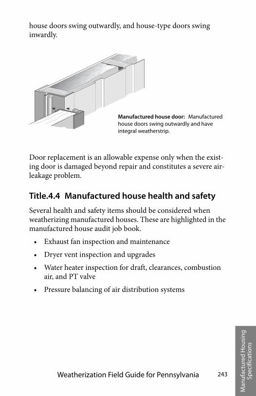
Man
ufac
ture
d H
ousi
ng
Spec
ifica
tion
s
Weatherization Field Guide for Pennsylvania 243
house doors swing outwardly, and house-type doors swing inwardly.
Door replacement is an allowable expense only when the exist-ing door is damaged beyond repair and constitutes a severe air-leakage problem.
Title.4.4 Manufactured house health and safety
Several health and safety items should be considered when weatherizing manufactured houses. These are highlighted in the manufactured house audit job book.
• Exhaust fan inspection and maintenance
• Dryer vent inspection and upgrades
• Water heater inspection for draft, clearances, combustion air, and PT valve
• Pressure balancing of air distribution systems
Manufactured house door: Manufactured house doors swing outwardly and have integral weatherstrip.

Man
ufac
ture
d H
ousi
ng
Spec
ifica
tion
s
244
Ap
pen
dic
es
Weatherization Field Guide for Pennsylvania 245
A–1 APPENDICES
Appendices . . . . . . . . . . . . . . . . . . . . . . . . . . . . . . . . . . . . 245
Weatherization Glossary . . . . . . . . . . . . . . . . . . . . . . . 257
Tables and Illustrations . . . . . . . . . . . . . . . . . . . . . . . . . 291
Index . . . . . . . . . . . . . . . . . . . . . . . . . . . . . . . . . . . . . . . . . . 297

Ap
pen
dic
es
Appendices246
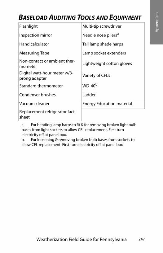
Ap
pen
dic
es
Weatherization Field Guide for Pennsylvania 247
BASELOAD AUDITING TOOLS AND EQUIPMENT Flashlight Multi-tip screwdriver
Inspection mirror Needle nose pliersa
a. For bending lamp harps to fit & for removing broken light bulb bases from light sockets to allow CFL replacement. First turn electricity off at panel box.
Hand calculator Tall lamp shade harps
Measuring Tape Lamp socket extenders
Non-contact or ambient ther-mometer
Lightweight cotton gloves
Digital watt-hour meter w/3-prong adapter
Variety of CFL’s
Standard thermometer WD-40b
b. For loosening & removing broken bulb bases from sockets to allow CFL replacement. First turn electricity off at panel box
Condenser brushes Ladder
Vacuum cleaner Energy Education material
Replacement refrigerator fact sheet
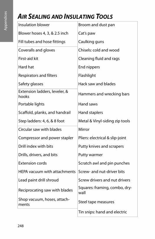
Ap
pen
dic
es
248
AIR SEALING AND INSULATING TOOLSInsulation blower Broom and dust pan
Blower hoses 4, 3, & 2.5 inch Cat’s paw
Fill tubes and hose fittings Caulking guns
Coveralls and gloves Chisels: cold and wood
First-aid kit Cleaning fluid and rags
Hard hat End nippers
Respirators and filters Flashlight
Safety glasses Hack saw and blades
Extension ladders, leveler, & hooks
Hammers and wrecking bars
Portable lights Hand saws
Scaffold, planks, and handrail Hand staplers
Step ladders: 4, 6, & 8 foot Metal & Vinyl-siding zip tools
Circular saw with blades Mirror
Compressor and power stapler Pliers: electrical & slip-joint
Drill index with bits Putty knives and scrapers
Drills, drivers, and bits Putty warmer
Extension cords Scratch awl and pin punches
HEPA vacuum with attachments Screw- and nut-driver bits
Lead paint drill shroud Screw drivers and nut drivers
Reciprocating saw with bladesSquares: framing, combo, dry-wall
Shop vacuum, hoses, attach-ments
Steel tape measures
Tin snips: hand and electric
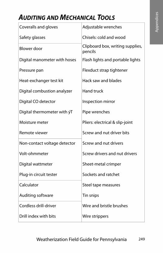
Ap
pen
dic
es
Weatherization Field Guide for Pennsylvania 249
AUDITING AND MECHANICAL TOOLSCoveralls and gloves Adjustable wrenches
Safety glasses Chisels: cold and wood
Blower door Clipboard box, writing supplies, pencils
Digital manometer with hoses Flash lights and portable lights
Pressure pan Flexduct strap tightener
Heat-exchanger test kit Hack saw and blades
Digital combustion analyzer Hand truck
Digital CO detector Inspection mirror
Digital thermometer with ýT Pipe wrenches
Moisture meter Pliers: electrical & slip-joint
Remote viewer Screw and nut driver bits
Non-contact voltage detector Screw and nut drivers
Volt-ohmmeter Screw drivers and nut drivers
Digital wattmeter Sheet-metal crimper
Plug-in circuit tester Sockets and ratchet
Calculator Steel tape measures
Auditing software Tin snips
Cordless drill-driver Wire and bristle brushes
Drill index with bits Wire strippers

Ap
pen
dic
es
250
WEATHERIZATION MATERIALS AND INVENTORYCellulose Assorted wire nuts and electrical
connectorsClosed-cell foam tape Compact fluorescent lamps
Fiberglass batts Energy-saving shower heads
Fiberglass blowing wool Programmable thermostats
Fiberglass duct wrap Replacement fan controls
Foam backer rod Replacement furnaces
Foam pipe sleeves Replacement refrigerators
One-part squirt foam Replacement water heaters
Sheet foam insulation 1/4-inch plywood or hardboard
Two-part spray foam Assorted lumber
Water heater insulation Assorted screws and nails
Assorted chimney pipe Assorted staples
Assorted furnace filters Construction adhesive
Duct mastic and web tape Disposable coveralls, boot cov-ers, and gloves
Duct tape and electrical tape Disposable paint brushes
Furnace filter material Plastic garbage bags
Proper vents Plastic sheeting
Sheet metal Pop riveter
Acoustical sealant Putty tape
Bronze v-seal weatherstrip Silicone or urethane caulk
Jamb-up weatherstrip Siliconized acrylic-latex caulk
Client-education booklets Portable tape recorder
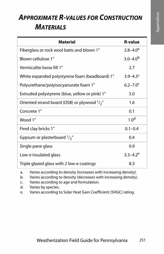
Ap
pen
dic
es
Weatherization Field Guide for Pennsylvania 251
APPROXIMATE R-VALUES FOR CONSTRUCTION MATERIALS
Material R-value
Fiberglass or rock wool batts and blown 1” 2.8–4.0a
a. Varies according to density (increases with increasing density).
Blown cellulose 1” 3.0–4.0b
b. Varies according to density (decreases with increasing density).
Vermiculite loose fill 1” 2.7
White expanded polystyrene foam (beadboard) 1” 3.9–4.3a
Polyurethane/polyisocyanurate foam 1” 6.2–7.0c
c. Varies according to age and formulation.
Extruded polystyrene (blue, yellow or pink) 1” 5.0
Oriented strand board (OSB) or plywood 1/2” 1.6
Concrete 1” 0.1
Wood 1” 1.0d
d. Varies by species.
Fired clay bricks 1” 0.1–0.4
Gypsum or plasterboard 1/2” 0.4
Single pane glass 0.9
Low-e insulated glass 3.3–4.2e
e. Varies according to Solar Heat Gain Coefficient (SHGC) rating.
Triple glazed glass with 2 low-e coatings 8.3
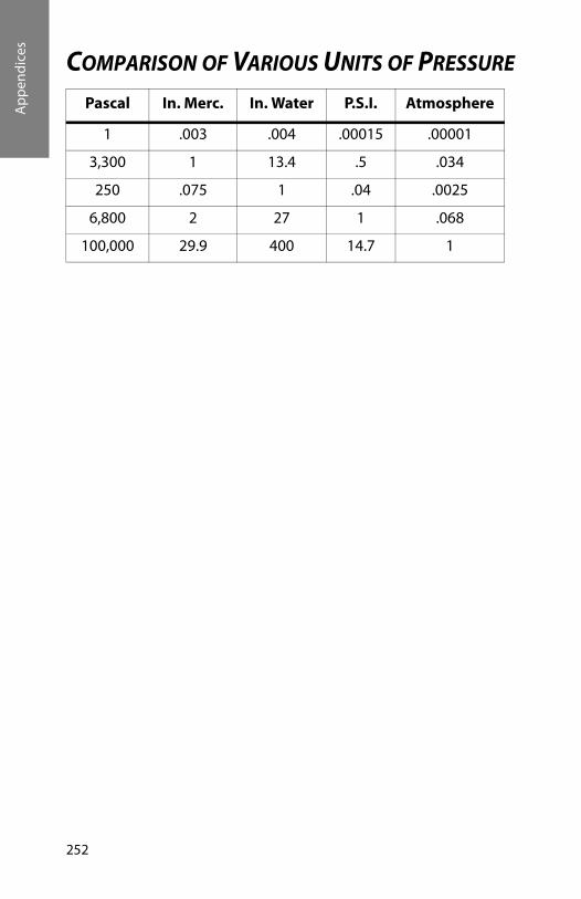
Ap
pen
dic
es
252
COMPARISON OF VARIOUS UNITS OF PRESSURE
Pascal In. Merc. In. Water P.S.I. Atmosphere
1 .003 .004 .00015 .00001
3,300 1 13.4 .5 .034
250 .075 1 .04 .0025
6,800 2 27 1 .068
100,000 29.9 400 14.7 1

Ap
pen
dic
es
Weatherization Field Guide for Pennsylvania 253
EFFICIENCY TABLE FOR # 2 FUEL OIL O2% 300° 350° 400° 450° 500° 550° 600° CO2%
15 75 72 69 66 63 60 56 4.514 77 74 72 70 68 64 61 513 79 77 75 72 70 67 65 612 80 78 76 74 72 70 68 6.511 82 80 78 76 74 72 70 7.510 83 81 79 77 76 74 72 8.59 84 82 80 79 77 75 74 98 84 83 81 80 78 77 75 107 85 83 82 80 79 77 76 10.56 85 84 83 81 80 78 77 115 86 85 83 82 81 79 78 11.54 86 85 84 83 81 80 79 12.53 87 85 84 83 82 81 79 132 87 86 84 83 82 81 80 141 87 86 85 84 83 82 81 15
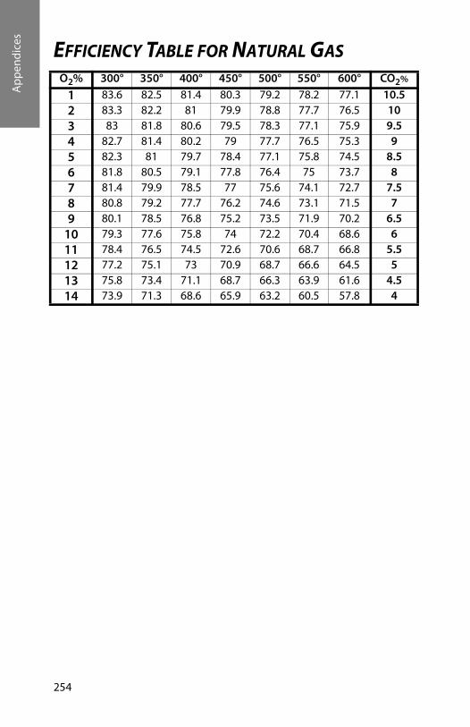
Ap
pen
dic
es
254
EFFICIENCY TABLE FOR NATURAL GASO2% 300° 350° 400° 450° 500° 550° 600° CO2%
1 83.6 82.5 81.4 80.3 79.2 78.2 77.1 10.52 83.3 82.2 81 79.9 78.8 77.7 76.5 103 83 81.8 80.6 79.5 78.3 77.1 75.9 9.54 82.7 81.4 80.2 79 77.7 76.5 75.3 95 82.3 81 79.7 78.4 77.1 75.8 74.5 8.56 81.8 80.5 79.1 77.8 76.4 75 73.7 87 81.4 79.9 78.5 77 75.6 74.1 72.7 7.58 80.8 79.2 77.7 76.2 74.6 73.1 71.5 79 80.1 78.5 76.8 75.2 73.5 71.9 70.2 6.5
10 79.3 77.6 75.8 74 72.2 70.4 68.6 611 78.4 76.5 74.5 72.6 70.6 68.7 66.8 5.512 77.2 75.1 73 70.9 68.7 66.6 64.5 513 75.8 73.4 71.1 68.7 66.3 63.9 61.6 4.514 73.9 71.3 68.6 65.9 63.2 60.5 57.8 4
Ap
pen
dic
es
Weatherization Field Guide for Pennsylvania 255
RESOURCES
Residential Energy: Cost Savings and Comfort for Existing Buildings, by John Krigger, Fifth Edition, 2009
Your Manufactured House: Energy and Repair Guide for Manufactured Housing, by John Krigger, Fourth Edition, 1998
Northeast Weatherization Field Guide, by John Krigger, First Edition, October 2001
Weatherization Guidebook for the Mid-Atlantic Region, by John Krigger, First Edition, 2000
Weatherization Standards, Illinois Home Weatherization Assistance Program, with John Krigger, First Edition, 1999
Weatherization Training Manual for Housing Technicians I & II, by John Krigger, First Edition, 1997
North Dakota Energy Saver Guidebook, by John Krigger, First Edition 2002
Montana Energy Saver Guidebook, by John Krigger, First Edition 2001

Ap
pen
dic
es
256
Wea
ther
izat
ion
Glo
ssar
y
Weatherization Field Guide for Pennsylvania 257
WEATHERIZATION GLOSSARY Absolute Humidity - AH: Air moisture content expressed in grains (or pounds) of water vapor per pound of dry air.
Absorptance : The ratio of a solar energy absorbed to incident solar. Also called absorptivity.
Absorption: A solid material's ability to draw in and hold liquid or gas.
Accent Lighting : Accent lighting illuminates walls, reduces brightness and contrast between walls and ceilings or windows.
Adsorption : Adhesion of a thin layer of molecules to a surface they contact.
Air Barrier : Any part of the building shell that offers resistance to air leakage. The air barrier is effective if it stops most air leak-age. The primary air barrier is the most effective of a series of air barriers.
Air Changes per Hour at 50 Pascals - ACH: The number of times the volume of air in a structure will change in one hour at the induced blower door house pressure of 50 pascals.
Air Exchange : The total building air exchanged with the out-doors through air leakage and ventilation.
Air Handler : A steel cabinet containing a blower with cooling and/or heating coils connected to ducts that transports indoor air to and from the air handler.
Air Infiltration Barrier : A woven plastic sheet that stops almost all air traveling through a building cavity, while allowing mois-ture to pass through the cavity.
Air Sealing : Also known as “house doctoring,” air sealing is a systematic approach to “tightening” a dwelling unit's heated envelope (building shell) to reduce uncontrolled heat loss through air leakage points present in the shell. The prevalent technique is to perform this tightening from the interior of the home. Trained workers seal the air leakage points using a variety
Wea
ther
izat
ion
Glo
ssar
y
Weatherization Glossary 258
of materials, such as insulation, caulk, foam, vapor barriers, and weather-strip. Air leakage identification is usually aided by using diagnostic equipment like blower doors and infrared scanners, since many leakage point are not obvious to the naked eye. Part of the air sealing protocol includes testing to ensure that the building envelope is not sealed too tightly. Over-tight-ening can result in health and safety problems for the occu-pants, including back drafting of combustion equipment (furnaces, hot water heaters) and moisture condensation caus-ing mold and mildew on surfaces.
Ambient lighting : Lighting spread throughout the lighted space for safety, security, and aesthetics.
American Society for Testing and Materials: ASTM
American Society of Heating, Refrigeration, and Air Conditioning Engineers: ASHRAE
AmericanWire Gauge : AWG
Ampere - A, Amp: A unit of measure for the flow of electric cur-rent
Annual Fuel Utilization Efficiency - AFUE : A laboratory-derived efficiency for heating appliances that accounts for chim-ney losses, jacket losses, and cycling losses, but not distribution losses or fan/pump energy.
Annual Return : The yearly savings divided by the initial cost needed to achieve the savings, expressed as a percent.
Aquastat : A heating control device that controls the burner or the circulator in a hydronic heating system
Asbestos : A material made of sharp mineral fibers that damage lung and other bodily tissues.
Attic Insulation : The installation of approved insulation prod-ucts (rockwool, fiberglass, and cellulose) evenly across the unconditioned attic area to achieve desired levels of thermal resistance. Insulation products have manufacturer rated “R” val-ues (resistance to heat loss measurements). The more inches of
Wea
ther
izat
ion
Glo
ssar
y
Weatherization Field Guide for Pennsylvania 259
insulation installed the higher the resistance level. The recom-mended “R” values vary by climatic regions of the country. It is common for weatherization programs to install a minimum of R-19 or as much as R-38 in colder regions. The cost-effective level of insulation to be added, if any, depends on the existing level of insulation in the attic. Auditors determined the amount of insulation to be added through prescriptive lists or energy audit programs that calculate the saving to investment ratio from increasing insulation levels.
Attic Preparation : This refers to the protocol for inspecting and preparing an attic area for the installation of insulation. The pre-paratory work is directed primarily to air infiltration and safety issues. Some of the protocols include placing barriers around heat-producing sources in the attic (electrical junction boxes, recessed lights, etc.); placing chutes by the eaves to prevent the insulation from blocking needed air ventilation paths; and seal-ing bypasses and other penetrations between the heated space and the unconditioned attic area.
Audit : The process of identifying energy conservation opportu-nities in buildings.
Back-drafting : Continuous spillage of combustion gases from a combustion appliances
Back-draft Damper : A damper, installed near a fan, that allows air to flow in only one direction.
Backer Rod : Polyethylene foam rope used as a backer for caulk-ing.
Baffle : A plate or strip designed to retard or redirect the flow of flue gases.
Balance point : The outdoor temperature at which no heating is needed.
Balance Heating: This is the result of balancing the airflow of the central heating distribution system so that intake and output air exists at levels to maximize efficiency. The balancing of the dis-tribution system assures that all areas of the home being served
Wea
ther
izat
ion
Glo
ssar
y
Weatherization Glossary 260
by the same heating or cooling system or any zone within the system receive approximately equal heated or cooled air.
Ballast : A coil of wire or electronic device that provides a high starting voltage for a lamp and limits the current flowing through it
Band Joist : See -Rim Joist
Batt : A narrow blanket of fiberglass insulation, generally 14.5" or 22.5" wide.
Beam : A strong horizontal building support used to carry the weight of a floor or roof.
Bimetal Element : A metal spring, lever, or disc made of two dis-similar metals that expand and contract at different rates as the temperature around them changes. This movement operates a switch in the control circuit of a heating or cooling device.
Blower Door : A blower door is a diagnostic tool used to locate the points of infiltration in the building envelope and help pri-oritize the air sealing protocols. This device can be mounted in an exterior door or window opening. The blower door uses a calibrated, powerful, variable speed fan to pressurize or depres-surize the dwelling. its adjustable frame allows the fan assembly to fit snugly in most frames. Air movement and pressure differ-entials are measured using a set of gauges attached to the frame and fan. These calculations of air movement allow technician to quantify the level of leakage. Such leakage measurements are usually expressed in terms of equivalent leakage area (ELA), air changes per hour (ACH), and cubic feet per minute of airflow (CFM). Anyone or more of these measurements can help deter-mine levels of air leakage, indoor air quality, and amount of seal-ing work to be performed. In addition to measuring air movement, the blower door will exaggerate the leakage points in the building shell for easy identification. This diagnostic tool, when used in conjunction with an infrared scanner, produces even more accurate results.
Wea
ther
izat
ion
Glo
ssar
y
Weatherization Field Guide for Pennsylvania 261
Blow-Down : The act of removing water from a boiler to remove sediment and suspended particles.
Blower Fan : The squirrel-cage fan in a furnace or air handler.
Boiler : A fossil fuel appliance used for producing hot water or steam as the medium to distribute heat to the dwelling unit.
Boot : A duct section that connects between a duct and a register or between round and square ducts
Branch Circuit : An electrical circuit used to power outlets and lights within a home.
Brightness : The intensity of the sensation derived from viewing a lit surface. Measured in footlamberts, it is also called lumi-nance or luminous intensity.
British Thermal Unit - Btu: The quantity of heat required to raise the temperature of one pound of water one degree Fahren-heit.
Building Cavities : The spaces inside walls, floors, and ceilings between the interior and exterior sheeting
Building Envelope : The area of the building that encloses condi-tioned space. Only the exterior four walls to the ceiling under the attic and the floor above the unheated basement area are considered part of the building envelope. The floor of a unit that is built on stilts or is above an unheated crawl space is consid-ered a part of the building envelope. The roof of a building that has no ceilings (or that is part of the ceiling) is considered part of the building envelope.
Building Science : Branch of science dealing with construction, maintenance, safety, and energy efficiency of buildings.
Burner : A device that facilitates the burning of a fossil fuel, like gas or oil.
Carbon Dioxide - CO2: One of two main products of complete combustion of a hydrocarbon (the other is water vapor).
Wea
ther
izat
ion
Glo
ssar
y
Weatherization Glossary 262
Carbon Monoxide - CO : Carbon Monoxide is a tasteless, odor-less, colorless and poisonous gas that is a by-product of incom-plete combustion of fossil fuels. It is usually caused by a lack of air to support combustion or impingement of the flame.
Casing : Exposed molding or trim around a window or door.
Caulking : Mastic compound for filling joints and cracks.
Cellulose Insulation : Insulation, packaged in bags for blowing, made from newspaper or wood waste and treated with a fire retardant
Centigrade - C °: A temperature scale on which water freezes at 0 degrees and boils at 100 degrees
Central Heating System : This refers to the primary heating sys-tem of the dwelling unit including the heat producing appliance, the return and supply system for heat distribution, and ducts or pipes for flue gas ventilation. Central heating systems usually do rtinclu.de wood stoves, kerosene heaters, space heaters, and electric baseboard heating units.
CFM - Cubic Feet per Minute : A measurement of air movement past a certain point or through a certain structure. Usually seen as CFM 50, cubic feet per minute of air movement due to 50 pascal house/outdoor pressure differential.
CFM50 - Cubic Feet per Minute @ 50Pa. : This term means the amount of cubic feet per minute of air moving through a struc-ture and measured at 50pascal pressure.
CFMn - Cubic Feet per Minute Natural: The cubic feet of air flowing through a house from indoors to outdoors during typi-cal, natural conditions. This figure can be roughly estimated using a blower door.
CFM Per Person or Per Room : An estimate of the cubic feet per minute of fresh air available or required per occupant or per room.
Wea
ther
izat
ion
Glo
ssar
y
Weatherization Field Guide for Pennsylvania 263
Circuit Breaker : A device found in a Circuit Panel Box that completes an electric circuit. This breaker disconnects the cir-cuit from electricity when it senses an overload of current.
Clean and Tune - C& T : A procedure performed on a heating system by a licensed furnace service technician to maximize the appliance efficiency using existing hardware. The C& T is usu-ally preceded by a combustion efficiency test to assess whether other conditions exist requiring extensive furnace work. The C&T can involve a variety of activities to upgrade the efficiency and safe operation of the heating system. These can include pilot and burner adjustment, adjustment of ventilation and combus-tion, check and reset controls, inspect filters, lubricate motors, flush low water cut-off, check operation of steam and water relief valves, check thermostat, check safety valve, and check thermocouple.
Co-efficient of Performance - COP: A heat pump or air condi-tioner's output in watt-hours of heat moved divided by watt-hours of electrical input.
Coil : A snake-like piece of copper tubing surrounded by rows of aluminum fins that clamp tightly to the tubing and aid in heat transfer.
Color Rendering Index - CRI: A measurement of a light source's ability to render colors the same as sunlight. CRI has a scale of 0 to 100.
Color Temperature : A measurement of the warmness or cool-ness of a light source in the Kelvin temperature scale.
Column : A vertical building support usually made of wood or steel.
Combustible : Means something will burn, although not neces-sarily readily.
Combustion Air: Air that chemically combines with a fuel dur-ing the combustion process to produce heat and flue gases, mainly carbon dioxide and water vapor.

Wea
ther
izat
ion
Glo
ssar
y
Weatherization Glossary 264
Combustion Analyzer: A device used to measure steady-state efficiency of combustion heating units.
Combustion Chamber: The area inside the heat exchanger where the flame burns
Combustion Test : This test is performed to determine the effi-ciency at which a heating appliance is operating at steady state. The actual tests or sequence of tests may vary in conjunction with the type of testing equipment used or the type of heating appliance being tested. Persons performing these tests must be extremely familiar with the testing equipment being used and must be trained in conducting the tests. In some states, a license is required to perform such tests.
Compressor : A motorized pump that compresses the gaseous refrigerant and sends it to the condenser where heat is released.
Condensate : Vapor condensed back to a liquid.
Condensate Receiver : A tank for catching returning condensate water from a steam heating system.
Condense : When a gas turns into a liquid as it cools, it con-denses. Condensation is the opposite of evaporation. When a gas condenses into a liquid it releases heat.
Condenser : The coil in an air conditioning system where the refrigerant condenses and releases heat, that is carried away by air moving through the coil.
Conditioned : Intentionally heated or cooled areas of a building
Conductance : The property of a material to conduct some energy form like heat or electricity.
Conduction : Conduction is the transfer of heat through a mate-rial by molecular movement. Reducing heat loss through con-duction can include the installation insulation in wall, ceiling, and floor cavities, insulation of hot water tanks, creating ther-mal breaks in window and door framing, and sealing of bypasses and other sources of air movement.
Wea
ther
izat
ion
Glo
ssar
y
Weatherization Field Guide for Pennsylvania 265
Contrast : Difference in brightness measured by the relationship between an object's brightness and the brightness of its back-ground.
Control Circuit : A circuit whose work is switching a power cir-cuit or opening an automatic valve
Convection : The transfer of heat caused by the movement of a fluid like water or air. When a fluid becomes warmer it becomes lighter and rises.
Convective Air Flow : Air movement where less dense (warmer) air is displaced by more dense (cooler) air. Often expressed by the phrase “hot air rises.” Convective air flow can be useful if controlled, as in gravity hot air heating systems, but is more often a contributor to heat loss.
Convective loop : A structural heat loss resulting from tempera-ture differences between the inside and outside wall surfaces causing an air movement loop within the wall cavity. This con-dition can be present when a stud cavity has no insulation. Air in the cavity is heated near the interior surface of the wall, rises, circulates back toward the exterior siding, falls, re-circulates back to the warm side, is re-heated, and so on.
Cooling Load : The maximum rate of heat removal required of an air conditioner when the outdoor temperature and humidity are at the highest expected level.
Cost Effective : Having an acceptable payback, return-on-invest-ment, or savings-to-investment ratio.
Cross Section : A view of a building component drawn or imag-ined by cutting through the component.
Community Services Block Grant - CSBG: The Community Ser-vices Block Grant (CSBG) is federal, anti-poverty block grant which funds the operations of a state-administered network of local agencies. This CSBG network consists of more than 1,100
Wea
ther
izat
ion
Glo
ssar
y
Weatherization Glossary 266
agencies that create, coordinate and deliver programs and ser-vices to low-income Americans in 96% of the nation's counties.
Most agencies in the CSBG network are Community Action Agencies (CAAs), created through the Economic Opportunity Act, a predecessor of the CSBG. Community representation and accountability are hallmarks of the CSBG network, where agen-cies are governed by a tri-partite board. This structure consists of elected public officials, representatives of the low-income community, and appointed leaders from the private sector. Because the CSBG funds the central management and core activities of these agencies, the CSBG network is able to mobi-lize additional resources to combat the central causes of poverty.
Curtain Wall: A wall between columns and beams that supports no weight but its own
Customer Certification : A final determination concerning pro-gram eligibility based on income and ownership, resulting in the customer's receipt or denial of WAP benefits.
Dado : A rectangular groove cut into wood.
Decking : The wood material installed under roofing material to support the roofing.
Demand for Energy - Charge: The peak need for electrical energy. Some utilities levy a monthly charge for demand.
Demand Side Management - DSM : The planning and imple-mentation of those utility sponsored activities designed to influ-ence customer use of electricity or gas in ways that will produce desired changes in the utility's load shape, such as changes in the pattern and magnitude of the utility's load. DSM study has resulted in a variety of utility-sponsored programs to redirect their customer's usage patterns, especially in the peak load peri-ods. While mainly an electric utility applied concept, there is some application to gas utilities as well. The ultimate goal for most utilities is to avoid the need to invest in new power plants or distribution due to excessive demands on current capacity.
Wea
ther
izat
ion
Glo
ssar
y
Weatherization Field Guide for Pennsylvania 267
Density : The weight of a material divided by its volume, usually measured in pounds per cubic foot.
Degree Days : A measure of the temperature element of climate produced by multiplying temperature difference by time.
Depressurize: Cause to have a lower pressure or vacuum with respect to a reference of a higher pressure.
Desiccant : A liquid or solid material used to absorb water or water vapor.
Design Temperature : A high or low temperature used for designing heating and cooling systems.
Dew Point : The warmest temperature of an object in an envi-ronment where water condensation from the surrounding air would form on that object
Dilution Air : Air that enters through the dilution device-an opening where the chimney joins to an atmospheric-draft com-bustion appliance
Dilution Device : A draft diverter or barometric draft control on an atmospheric-draft combustion appliance.
Distribution System : This term refers to that part of a central heating system used to deliver heated transfer media to the liv-ing space, and return the cooled transfer media to the appliance for re-heating. In a forced air system this includes the blower, ducts, registers, dampers, and cold air returns. In a hot water system this includes circulators, supply lines, radiators, and return lines.
DOE: - Department of Energy
Domestic Hot Water (DHW) : Refers to a separate, closed system to heat potable (drinkable) water and supply it to the dwelling unit for washing, bathing, etc.
Dormer : A vertical window projecting from a roof.
Wea
ther
izat
ion
Glo
ssar
y
Weatherization Glossary 268
Draft Diverter : A device located in gas appliance flue pipe. Used to moderate or divert draft that could extinguish the pilot or interfere with combustion
Drywall : Gypsum interior wallboard used to produce a smooth and level interior wall surface and to resist fire. Also called gyp-sum wall board or sheetrock.
Dry Bulb Temperature : Normal ambient air temperature mea-sured by a thermometer.
Duct Blower : A blower-door-like device used for testing duct leakiness and air flow.
Duplex : Any structure which consists of two separate dwelling units in one building.
Dwelling Unit : A house, including a stationary manufactured home, an apartment, a group of rooms, or a single room occu-pied as separate living quarters.
Eaves : The edges of a roof system (See -Soffit)
Efficiency : The ratio of output divided by input
Efficacy : The number of lumens produced by a watt used for lighting a lamp. Used to describe lighting efficiency.
Eligible Multi-Family Dwelling Units : A multi-family building qualifies to be weatherized in its entirety when 66% (50% for 2 and 4 unit buildings) or more of the total dwelling units in the building are determined to be eligible as per DOE rules.
Eligible Unit : A unit occupied by a household that is categori-cally eligible or income eligible by DOE and/or LlHEAP stan-dards.
Emittance : The ability of a material to emit radiant energy from its surface. Also called emissivity.
Energy : A quantity of heat or work

Wea
ther
izat
ion
Glo
ssar
y
Weatherization Field Guide for Pennsylvania 269
Energy Consumption : The conversion or transformation of potential energy into kinetic energy for heat, light, electricity, etc.
Energy Education : The process used by WAP staff to inform customers of the ways they can further reduce energy consump-tion through altering their behavioral patterns. The most effec-tive protocol includes multiple interaction and reinforcement with the household residents and use of a negotiated and written action plan.
Energy Efficiency : Term used to describe how efficiently a building component uses energy.
Energy Efficiency Ratio - EER : A measurement of energy effi-ciency for room air conditioners. The EER is computed by dividing cooling capacity, measured in British Thermal Units per hour (Btuh), by the watts of power. (See -Seasonal Energy Efficiency Rating or SEER)
Enthalpy : The internal heat of a material measured in Btus per pound.
Entropy : Heat unavailable to a closed thermodynamic system during a heat transfer process.
Environmental Protection Agency - U.S. EPA: EPA’s mission is to protect human health and to safeguard the natural environment - air, water, and land - upon which life depends. For 30 years, EPA has been working for a cleaner, healthier environment for the American people.
Equivalent Leakage Area (ELA) : Calculation, in square inches, of the total area of all holes and cracks in a structure. The leak-age area is then accumulated to represent one total leakage point.
Evaporation : The change that occurs when a liquid becomes a gas. Evaporation is the key process in the operation of air condi-tioners and evaporative coolers.
Wea
ther
izat
ion
Glo
ssar
y
Weatherization Glossary 270
Evaporative Cooler : A device for cooling homes in dry climates by humidifying and cooling incoming air.
Evaporator : The heat transfer coil of an air conditioner or heat pump that cools the surrounding air as the refrigerant inside the coil evaporates and absorbs heat.
Exfiltration : This term describes the movement of air out of a building. Often refers to warm air leaving a building due to pres-surization, infiltration, wind, stack effect, and/or convective flow.
Fahrenheit - F°: A temperature scale used in the United States and a few other countries. On the Fahrenheit scale, water boils at 212 degrees and freezes at 32 degrees.
Family Unit : All persons living together in a dwelling unit
Fan Control : A bimetal thermostat that turns the furnace blower on and off as it senses the presence of heat.
Federal Energy Management Program - FEMP: A program of DOE that implements energy legislation and presidential direc-tives. FEMP provides project financing, technical guidance and assistance, coordination and reporting, and new initiatives for the federal government. It also helps federal agencies identify the best technologies and technology demonstrations for their use.
Fenestration : Window and door openings in a building's wall.
Fiberglass : A fibrous material made by spinning molten glass used as an insulator and heat loss retardant.
Fill Tube: A plastic or metal tube used for its stiffness to blow insulation inside a building cavity.
Fin Comb : A comb-like tool used to straighten bent fins in air conditioning coils.
Fire Stop : Framing member designed to stop the spread of fire within a wall cavity.
Wea
ther
izat
ion
Glo
ssar
y
Weatherization Field Guide for Pennsylvania 271
Flame Safety Control : A control device used to stop the flow of fuel to the burner assembly in the event of no ignition.
Flashing : Waterproof material used to prevent leakage at inter-sections between the roof surface at walls or penetrations.
Floor Joists : The framing members that support the floor area.
Flue : The channel of pipe used to control air flow of combus-tion gases.
Foam Board : Plastic foam insulation manufactured most com-monly in 4'x8' sheets in thickness of 1/4“ to 3".
Foot Candle : A measure of light striking a surface
Footer : The part of a foundation system that actually transfers the weight of the building to the ground
Frost Line : The maximum depth of the soil where water will freeze during the coldest weather
Furnace : An appliance for heating a medium to distribute heat throughout the dwelling unit.
Gable : The triangular section of an end wall formed by the pitch of the roof.
Gas Heating System : A heating system that uses natural gas or bottled liquid propane gas as fuel.
Gasket : Elastic strip that seals a joint between two materials.
Glazing : Glass installation. Pertaining to glass assemblies or windows
Glass Load Factor : A number combining glass's solar heat transmission and its heat conduction. Used for cooling load cal-culations.
Gravity Furnace : A central heating system that uses natural gravity to distribute heat throughout the dwelling unit as opposed to forced circulation, pumps, or circulation blowers.
Gusset : A metal or wood plate added to the surface of a joint to strengthen the connection.
Wea
ther
izat
ion
Glo
ssar
y
Weatherization Glossary 272
Gypsum Board : A common interior sheeting material for walls and ceilings made of gypsum rock powder packaged between two sheets of heavy building paper. Also called sheetrock, gyprock, or gypboard.
Handicapped Person : Any individual who is: 1) handicapped as defined in Section 7 (6) of the Rehabilitation Act of 1973; 2) under a disability as defined in Section 1614 (1) (3) (A) or 223 (d) (i) of the Developmental Disabilities Services and Facilities Construction Act; or 3) who is receiving benefits under Chapter 11 or 15 of Title 38, U.S.C. Other conditions may apply state to state, which can deem an individual as handicapped for the pur-poses of the WAP.
Heat Anticipator : A very small electric heater in a thermostat that causes the thermostat to turn off before room temperature reaches the thermostat setting, so that the house does not over-heat from heat remaining in the furnace and ducts after the burner shuts off.
Heat Capacity : The quantity of heat required to raise the tem-perature of 1 cubic foot of a material 1 degree F.
Heat Gains : Term used to mean unwanted heat that accumu-lates in homes, making mechanical cooling desirable or neces-sary.
Heat Loss : The amount of heat escaping through the building shell as measured for a specific period of time (month, year, etc.)
Heat Transmission : Heat flow through the walls, floor, and ceil-ing of a building, not including air leakage.
Heat Transfer Coefficient : See U-value.
Heating Degree Day - HDD): Each degree that the average daily temperature is below the base temperature (usually 65 degrees F) constitutes one heating degree day. Used to determine indoor space heating requirements and heating system sizing. Total HDD is the cumulative total for the year/heating season. The
Wea
ther
izat
ion
Glo
ssar
y
Weatherization Field Guide for Pennsylvania 273
higher the HDD for a location, the colder the daily average tem-perature(s).
Heating Load : The maximum rate ·of heat conversion needed by a building during the very coldest weather.
Heating Seasonal Performance Factor - HSPF : Rating for heat pumps describing how many Btus they transfer per kilowatt-hour of electricity consumed.
Home Energy Rating Systems: A nationally recognized energy rating program that give builders, mortgage lenders, secondary lending markets, homeowners, sellers, and buyers a precise eval-uation of energy losing deficiencies in homes. Builders can use this system to gauge the energy quality in their home and also to have a star rating on their home to compare to other similarly built homes.
Heating, Ventilation, and Air-Conditioning System - HVAC: All components of the appliances used to condition interior air of a building.
High Limit : A bimetal thermostat that turns the heating element of a furnace off if it senses a dangerously high temperature.
Home Heating Index : The number of Btus of energy used by a home divided by its area in square feet, then divided by the number of heating degree days during the time period.
HOME Program : A program created under Title II (the Home Investment Partnership Act) of the National Affordable Hous-ing Act of 1990. Provides funds for states to expand the supply of decent and affordable housing for low-income people. This program can be easily coordinated with a state's WAP efforts.
Household : Any individual or group of individuals who are liv-ing together as one economic unit for whom residential energy is customarily purchased in common or who make undesig-nated payments for energy in the form of rent.
House Pressure : The difference in pressure between the indoors and outdoors measured by a manometer.
Wea
ther
izat
ion
Glo
ssar
y
Weatherization Glossary 274
HUD : -U.S. Department of Urban Housing and Development
Humidistat: An automatic control that switches a fan, humidi-fier, or dehumidifier on and off to control relative humidity.
Humidity Ratio : Same as “absolute humidity.” The absolute amount of air's humidity measured in pounds of water vapor per pound of dry air.
Hydronic : A heating system that uses hot water or steam as the heat-transfer fluid.
Indoor Air Quality - IAQ: The quality of Indoor air relative to Its acceptability for healthful human habitation. Assessing and amelioratIng, when necessary, the quality of indoor air is a major concern of the weatherization process. In particular, all by-products of major combustion appliances must be directly evacuated to the outdoors under all operating conditions.
Illumination : The light level measured on a horizontal plane in Foot Candles
Inch of Water : Small air pressure differences caused by wind, blower doors, furnace fans, and chimneys are measured in inches of water (in.-H20) in the American measurement system.
Incidental Repairs : Under DOE rules, this term refers to the repairs on a dwelling unit necessary for the effective perfor-mance or preservation of the allowable energy conservation measures to be installed. Usually, a specific dollar amount is set by a state to limit such incidental repairs.
Indoor Air Quality - IAQ : Refers to the measurement of air quality in the living space of the home. Pollutants can exist within a home, and WAP staff must be aware of the impact their work has on the quality of the atmosphere within the living space. The presence of pollutants, combined with inadequate ventilation factors, can contribute to a variety of occupant health and safety problems. Therefore, IAQ is a primary concern when workers seal or “tighten” homes.
Wea
ther
izat
ion
Glo
ssar
y
Weatherization Field Guide for Pennsylvania 275
In-Kind Contributions : In-kind contributions represent the value of non-cash contributions provided by the grantee, and non-Federal parties. In-kind contributions may be in the form of charges for real property and non-expendable personal prop-erty and the value of goods and services directly benefiting and specifically identifiable to the project or program.
Infiltration : Infiltration refers to the movement of air into a building through cracks and penetrations in the building enve-lope. Cold air often enters the structure due to depressurization, exfiltration, wind, stack effect, and/or convective airflow.
Infrared Thermography : The science of using infrared imaging to detect radiant energy or heat loss characteristics of a building. The infrared camera or scanner electronically senses heat radi-ated by objects and converts that thermal energy into images visible to the human eye. The camera or scanner, similar to a camcorder in appearance, produces varying shades of black and white images of the building structure. The darker the image, the colder the corresponding surface; the lighter areas are the hotter surfaces. Some scanners can automatically record these images on video, as well as allow the operator to record audio commentary as he/she scans the building. A certain degree of interpretation skill is required to properly assess the images being recorded. Used in conjunction with a blower door, the scanner can provide valuable data, since the pressurization or depressurization can magnify air leakage sites and thermal bypasses.
Input Rating : The measured and assigned rating indicating the level at which an energy-using device consumes electricity or fossil fuel.
Insolation : The amount of solar radiation striking a surface
Insulated Glass : Two or more glass panes installed in windows and doors, spaced apart and sealed in a factory.
Wea
ther
izat
ion
Glo
ssar
y
Weatherization Glossary 276
Internal Gains : The heat generated by bathing, cooking, and operating appliances, that must be removed during the summer to promote comfort.
Intermittent Ignition Device : A device that lights the pilot on a gas appliance when the control system calls for heat, thus saving the energy wasted by a standing pilot.
Intermediate Zone : A zone located between the building's con-ditioned space and the outdoors, like a crawl space or attic.
Jamb : The side or top piece of a window or door frame.
Joist : A horizontal wood framing member that supports a floor or ceiling.
Kilowatt - KW: A unit of electric power equal to 1000 joules per second or 3412 Btus per hour.
Kilowatt-hour - KWH: A unit of electric energy equal to 3600 kilojoules.
Landlord/Tenant Agreement : Document required for completed application when applicant is a renter. The Agreement is legally binding contract, signed by the tenant, the landlord (or property owner), and the local agency specifying the role and responsibil-ities of each party. The basic goal of the WAP is to ensure that the benefits of the program accrue to the low-income family. A variety of standard clauses can be incorporated into the Agree-ment, including clauses on landlord's inability to raise rents for specified period of time, eviction prohibition, and landlord required “participation.” Participation can take the form of actual cash, provided labor, and/or in-kind contributions.
Leakage Ratio : Measurement of total square inches of infiltra-tion area per 100 feet of building envelope surface area.
Leverage Activity : The actions of the state and local agencies to obtain and account for resources provided to supplement or supplant federal funding being used to weatherize dwelling units.
Wea
ther
izat
ion
Glo
ssar
y
Weatherization Field Guide for Pennsylvania 277
Local Agency : Also referred to as the subgrantee, contractor, service delivery network member, or local service provider, a local agency is a nonprofit organization or unit of local govern-ment responsible for providing WAP services in a specified political subdivision.
Low-E : Short for “low emissivity”, which means the characteris-tic of a metallic glass coating to resist the flow of radiant heat.
Low Water Cutoff : A float-operated control for turning the burner off if a steam boiler is low on water.
Lumen : A unit of light output from a lamp.
Make-up Air : Air supplied to a space to replace exhausted air.
Manometer : Measuring device for small gas pressures.
Manufactured Home Energy Audit - MHEA: 'A software tool that predicts manufactured home energy consumption and rec-ommends weatherization retrofit measures.
Mastic : A thick creamy substance used to seal seams and cracks in building materials.
Mitigate : To make less severe or to mollify.
Mortar : A mixture of sand, water, and cement used to bond bricks, stones, or blocks together.
Mortise : A recessed area cut into the wood framing member where a hinge or wood tongue fits.
NASCSP National Association for State Community Services Pro-grams : NASCSP's mission is to assist state in responding to pov-erty issues. NASCSP members are state administrators of the Community Services Block Grant (CSBG) and U.S. Department of Energy's Weatherization Assistance Program (DOE/WAP). The CSBG, administered by the states, provides core funding to local agencies to reduce poverty, revitalize low-income commu-nities and to empower low-income families to become self-suffi-cient. The DOE/WAP helps low-income families reduce their energy costs by making homes more energy efficient. The local
Wea
ther
izat
ion
Glo
ssar
y
Weatherization Glossary 278
agencies funded by these programs provide a wide range of ser-vices such as weatherization, energy assistance, child care, job training, and housing. NASCSP keeps its members, the federal government, and other interested parties informed about issues related to CSBG and DOE/WAP through its publications.
Natural Ventilation : Ventilation using only natural air move-ment without fans or other mechanical devices.
NEAT -National Energy Audit : Created by Oak Ridge National Laboratories as a DOE approved audit qualifying for the 40% materials waiver. It is a computerized auditing tool for prioritiz-ing energy conservation measures for houses.
Net Free Area : The area of a vent after that area has been adjusted for insect screen, louvers, and weather covering. The free area is always less than the actual area.
Nozzle : An orifice for spraying a liquid like fuel oil.
Oil Heating System : Refers to a central heating system that uses #2 fuel oil, kerosene, or residual oil as the primary fuel for heat generation.
Open-Combustion Heater : A heating device that takes its com-bustion air from the surrounding room air.
Orifice : A hole in a gas pipe or nozzle fitting where gas or fuel oil exits to be mixed with air before combustion occurs in the heating chamber.
Oscillating Fan: A fan, usually portable, that moves back and forth as it operates, changing the direction of the air movement.
Output Capacity : The conversion rate of useful heat that a heat-ing unit produces after accounting for any waste caused by the conversion of energy into heat.
Oxygen Depletion Sensor: A safety device on a heating unit that shuts off the fuel supply to the combustion chamber when oxy-gen is depleted.
Wea
ther
izat
ion
Glo
ssar
y
Weatherization Field Guide for Pennsylvania 279
Packaged Air Conditioner : An air conditioner that contains the compressor, evaporator, and condenser in a single cabinet.
PA -Pascal : A unit of measurement of air pressure. One column inch of water equals 247 pascals. Atmospheric pressure (29.92 inches of mercury) is equivalent to 102,000 PA.
Payback Period : The number of years that an investment in energy conservation will take to repay its cost through energy savings.
Perlite : A heat-expanded mineral used for insulation.
Perm : A measurement of how much water vapor a material will let pass through it per unit of time.
Plaster : A plastic mixture of sand, lime, and Portland cement spread over wood or metal lath to form the interior surfaces of walls and ceilings.
Plate : A piece of lumber installed horizontally to which the ver-tical studs in a wall frame are attached.
Plenum : The piece of ductwork, usually found above the heat exchanger of a hot air furnace, that connects the air handler to the main supply duct.
Plumb : Absolutely vertical at a right angle to the earth's surface.
Plywood : Laminated wood sheeting with layers cross-grained to each other.
Polyethylene : Polymer plastic used for vapor barriers, air barri-ers, and foam backer rod.
Polyisocyanurate : A plastic foam insulation sold in sheets, simi-lar in composition to polyurethane.
Polystyrene Insulation : A rigid plastic foam insulation, usually white or blue in color.
Polyurethane: A versatile plastic foam insulation, usually yellow in color.

Wea
ther
izat
ion
Glo
ssar
y
Weatherization Glossary 280
Potential Energy : Energy in a stored or packaged form, like fuel oil, coal, wood, etc.
Pressure : A force encouraging movement by virtue of a differ-ence in some condition between two areas.
Pressure Diagnostics : The practice of measuring pressures and flows in buildings to control air leakage, and also to ensure ade-quate heating and cooling air flows and ventilation.
Pressure Pan : A device used to block a duct register while mea-suring the static pressure behind it.
Pressuretrol : A control that turns a steam boiler's burner on and off as steam pressure changes.
Prime Window : The main window installed on the outside wall consisting of fixed or moveable lights that slide on permanently fixed tracks (not to be confused with a storm window).
Priority list : The list or ranking of installation measures devel-oped by a program to produce the most cost effective energy savings results based on a savings to investment ratio calcula-tion.
Program Income: Income earned by the grantee from grant-sup-ported activities, including but not limited to, income from ser-vice fees, sale of commodities, usage or rental fees, and royalties on patents and copyrights.
Psychrometrics : The study of the relationship between air, water vapor, and heat.
Purlins : Framing members that sit on top of rafters, perpendic-ular to them, designed to spread support to roofing materials.
PV -Photovoltaic : A solid-state electrical device that converts light directly into direct current electricity of voltage-current characteristics that are a function of the characteristics of the light source and the materials in and design of the device. Solar photovoltaic devices are made of various semi-conductor mate-rials including silicon, cadmium sulfide, cadmium telluride, and
Wea
ther
izat
ion
Glo
ssar
y
Weatherization Field Guide for Pennsylvania 281
gallium arsenide, and in single crystalline, multi-crystalline, or amorphous forms.
R-Value : A measurement of thermal resistance for materials and related surfaces.
Radiant Barrier : A foil sheet or coating designed to reflect heat producing sun rays.
Radiant Temperature : The average reflective temperature of objects in a home, like walls, ceiling, floor, and furniture.
Radiation : Heat energy originating on a hot body like the sun and traveling from place to place through the air.
Radon : A radioactive gas that decomposes into radioactive par-ticles.
Rafter : A roof beam that follows the roofs slope.
Reflectance : Also called reflectivity, it is the ability of a mate-rial's surface to reflect radiant heat.
Recovery Efficiency : A water heater's efficiency at actually heat-ing water to capacity level without regard to standby or distribu-tion losses.
Reflective Glass : Glass that has a mirror-like coating on its exte-rior surface to reflect solar heat. The solar heat gain coefficient of reflective glass ranges from 0.10 to OAO.
Refrigerant : A special fluid used in air conditioners and heat pumps that heats air when it condenses from a gas to a liquid and cools air when it evaporates from a liquid to a gas.
Register : The grille cover over a duct outlet for warm air distri-bution or cold air return.
Relamping : The replacement of an existing, standard light bulbs with lower wattage energy efficient bulbs like compact fluores-cent lamps.
Wea
ther
izat
ion
Glo
ssar
y
Weatherization Glossary 282
Relative Humidity : The percent of moisture absorbed in the air compared to the maximum amount possible. For instance, air that is completely saturated has 100% relative humidity.
Relay : An automatic, electrically-operated switch.
Reset Controller : Adjusts fluid temperature or pressure in a cen-tral heating system according to outdoor air temperature.
Resistance : The property of a material resisting the flow of elec-trical energy or heat energy.
Retrofit : An energy conservation measure applied to an existing building or the action of improving the thermal performance or maintenance of a building.
Return Air : Air circulation back to the furnace from the house to be heated by the furnace and supplied to the rooms.
Re-Weatherized Unit : Any unit that received weatherization services prior to September 30, 1985 and has received additional services under subsequent grants or allowed by current DOE regulations.
Rim Joist : The outermost joist around the perimeter of the floor framing.
Savings-to-Investment Ratio (SIR) : They are computed over the lifetimes of the retrofit measures installed and expressed in terms of the net present value of the retail cost of the dwelling's fuel. Under some methodologies, other benefits, etc. Investment usally takes into account materials, labor, and support costs. SIRs of greater than one are counted as cost effective under this DOE WAP method of determining cost-effectiveness.
Sealed Combustion Heater : A heater that draws air for combus-tion from outdoors and has a sealed exhaust system.
Seasonal Efficiency : Refers to the overall efficiency of the central heating system including on and off cycle fuel utilization and heat loss. The calculation of these factors is represented in the Annual Fuel Utilization Efficiency (AFUE) rating for the appli-ance. Distribution system loss is not factored into the AFUE.

Wea
ther
izat
ion
Glo
ssar
y
Weatherization Field Guide for Pennsylvania 283
Seasonal Energy Efficiency Ratio - SEER: A measure of seasonal or annual efficiency of a central air conditioner or air condition-ing heat pump. It takes into account the variations in tempera-ture that can occur within a season and is the average number of Btu of cooling delivered for every watt-hour of electricity used by the heat pump over a cooling season.
Seasonal Performance Factor - SPF : Ratio of useful energy out-put of a device to the energy input, averaged over an entire heat-ing season.
Separate Living Quarters : Living quarters in which the occu-pants do not live and eat with any other persons in the structure and that have either a direct access from the outside of the building or through a common hall or complete kitchen facili-ties for the exclusive use of the occupants. The occupants maybe a single family, one person living alone, two or more families liv-ing together, or any other group of related or unrelated persons who share living arrangements.
Sequencer : A bimetal switch that turns on the elements of an electric furnace in sequence.
Settling : This term refers to the effect of insulation depressing over time and, thereby, reducing the overall energy efficiency of the materials. This process is primarily the result of using too much air when installing the blown-in insulation -commonly called “fluffing,” or the effect of long periods of time on the materials. One reason to reinspect some work several months after installation is to assess the settling factor. Settling can also occur during the installation of sidewall insulation when the cavity is not completely filled. This is usually avoided if “dense pack” protocols are followed during the installation.
Shading Coefficient (SC) : A decimal describing how much solar energy is transmitted through a window opening compared to clear single glass having an SC of 1.0. For example, reflective glass has an SC of 0.20 to 0.45.
Wea
ther
izat
ion
Glo
ssar
y
Weatherization Glossary 284
Sheathing : A structural sheeting, attached on top of the fram-ing, underneath siding, or on the roof of a building.
Sheeting : Common term for any building material used for cov-ering a building surface.
Shell : The building's exterior envelope including walls, floor, and roof.
Shingle : A modular roofing material, usually asphalt, that is installed in overlapping rows to cover the entire roof.
Short Circuit : A dangerous malfunction in an electrical circuit where electricity is flowing through conductors and into the ground without going through an electric load, like a light or motor.
Sidewall Insulation : The process of installing insulation mate-rial, usually blown cellulose, into the non-insulated wall stud cavities of a structure to reduce heat loss. installation is achieved by drilling one or more rows of holes into the wall, one in each stud cavity. To achieve the most effective results, a dense pack protocol is used to install “high density” insulation materials. The “packing” of the materials should be tight enough that the installer cannot move the insulation when complete. It is com-mon to install materials at 3.5 pounds per square foot.
Sill : The bottom of a window or door frame.
Sill Box : The outer area of the floor bound by the rim joist, floor joist, sill plate, and floor.
Sling Psychrometer : A device holding two thermometers that is slung through the air to measure relative humidity.
Soffit : The underside of a roof overhang or a small lowered ceil-ing, as above cabinets or a bathtub.
Solar Gain : Heat from the sun that is absorbed by a building's materials and contributes to the heating and cooling require-ments of the dwelling.
Wea
ther
izat
ion
Glo
ssar
y
Weatherization Field Guide for Pennsylvania 285
Solar Heat : Radiant energy from the sun with wavelengths between 0.7 and 1 micrometers.
Solar Heat Gain Coefficient - SHGC : The ratio of solar heat gain through a window to incident solar heat, including both trans-mitted heat and absorbed/radiated heat.
Solar Heat Gain Factor -SHGF : Solar heat gain amount on a surface with a particular angle and orientation expressed in Btus per square foot per hour.
Solar Transmittance : The percent of total solar energy transmit-ted by a material.
Solenoid : A magnetic device that moves a switch or valve stem.
Space Heating : Heating the living spaces of the home with a room heater or central heating system.
Span : Horizontal distance between supports.
Specific Heat : The ratio of the heat storage capacity of a particu-lar material to the heat storage capacity of water.
Spillage : Temporary flow of combustion gases from a dilution device.
Spline : A strip of vinyl, rubber, or plastic that, when inserted into a groove, holds a screen or plastic film in place on a frame.
Split-System Air Conditioner : An air conditioner having the condenser and compressor outdoors and the evaporator indoors.
Stack Effect : The term describes the effect of higher pressure at the top of a structure, lower pressure at the bottom of a struc-ture, and neutral pressure somewhere in between, relative to the ambient (surrounding) air pressure. It is usually the result of dif-ferent densities of warmer and cooler air (convective airflow).
Standing Loss : Heat loss from a hot water storage tank through its shell.
Wea
ther
izat
ion
Glo
ssar
y
Weatherization Glossary 286
Steady State Efficiency : The measurement of heat system bal-ance in the on-cycle when heat into system equals heat out. Generally provided as a percentage of the maximum available heat generation capacity (100%) against the amount of usable heat being sent to the distribution system. This figure can also represent the percentage of heat being used within the system as compared to the heat lost through the flue. The reading is most valid when the stack temperature becomes constant and the dis-tribution pumps or blowers are operating.
Steam Trap : An automatic valve that closes to trap steam in a radiator until it condenses.
Steam Vent : A bimetal-operated air vent that allows air to leave steam piping and radiators, but closes when steam strikes the surface.
Stop : A thin, trim board for windows and doors to close against or slide against.
Strike Plate : The metal plate attached to the door jamb that the latch inserts into upon closing.
Stud : A vertical wood or metal framing member used to build a wall.
Sub-Floor : The sheathing over the floor joists and under the floor covering.
Supply Air : Air that has been heated or cooled and is moved through the ducts and to the supply registers of a home.
Suspended Ceiling : Modular ceiling panels supported by a hang-ing frame.
Taped Duct Test -TDT: A procedure using the blower door to measure the “potential” for leakage reduction of the duct sys-tem. All supply registers and return grills are taped shut follow-ing the initial blower door reading and a subsequent air leakage test taken. if closing off the duct system in this manner causes an appreciable reduction in the air leakage rate, this is an indication that there are significant duct leaks.

Wea
ther
izat
ion
Glo
ssar
y
Weatherization Field Guide for Pennsylvania 287
Temperature Rise : The number of degrees of temperature increase that air is heated as it is blown over the heat exchanger. Temperature Rise equals supply temperature minus return tem-perature.
Therm : A unit of energy equal to 100,000 Btus or 29.3 kilowatt-hours.
Thermal Break : A relatively low heat/cold conductive material separating two highly conductive materials.
Thermal Bridging : Rapid heat conduction resulting from direct contact between very thermally conductive materials like metal and glass.
Thermal Bypass : Similar to a convection loop, this structural heat loss is characterized by heated air traveling up exterior or interior stud cavities and leaking out the top of that cavity to the attic through joints and cracks in the framing, wiring and plumbing holes, etc. These types of heat loss sources are some-times the most difficult to locate.
Thermal Conductance : General term applied to both K-value and U-value, meaning heat flow rate.
Thermocouple : A bimetal-junction electric generator used to keep the safety valve of an automatic gas valve open.
Thermodynamics : The science of heat.
Title XVI : Term to be used interchangeably with those income groups known as SSI (Supplemental Security Income) recipi-ents.
Tracer Gas : A harmless gas used to measure air leakage in a building.
Transformer : A double coil of wire that increases or decreases voltage from a primary circuit to a secondary circuit.
Trim : Decorative wood that covers cracks around window and door openings and at the corners where walls meet floors and ceilings. Sometimes called molding.
Wea
ther
izat
ion
Glo
ssar
y
Weatherization Glossary 288
Truss : A lightweight, rigid framework designed to be stronger than a solid beam of the same weight.
U-Value : The amount of heat flowing through a square foot of building materials.
Ultraviolet Radiation : Solar radiation having wavelengths just shorter than visible light.
Unconditioned Space : An area within the building envelope not intentionally or unintentionally heated.
Vapor Barrier : A material that retards the passage of water vapor.
Vapor Diffusion : The flow of water vapor through a solid mate-rial.
Veiling Reflection: Light reflection from an object or task that obscures details.
Veneer : The outer layer of a building component (e.g., interior doors often have a wood veneer; some wood-frame houses have brick veneer walls, etc.).
Vent Connector : The vent pipe carrying combustion gases from the appliance to the chimney.
Vent Damper : An automatic damper powered by heat or elec-tricity that closes the chimney while a heating device is off.
Venting : The removal of combustion gases by a chimney.
Ventilation : Refers to the controlled air exchange within a struc-ture. All dwellings must “breathe” and proper ventilation rates must be determined. If the structure requires more interior/exterior air exchanges, there are mechanical and non-mechani-cal options for increasing those rates. The most common option is passive ventilation through the installation of roof, soffit, or gable vents.
Vermiculite : A heat-expanded mineral used for insulation.
Wea
ther
izat
ion
Glo
ssar
y
Weatherization Field Guide for Pennsylvania 289
Visible Transmittance : The percent of visible light transmitted by a glass assembly.
Visqueen : Polyethylene film vapor barrier.
Watt : A unit electrical power equivalent to one joule per second or 3.4 Btuh
Watt-Hour : A unit of electrical energy equivalent to 3600 joules or 3.4 Btus.
Weatherization Assistance Program - WAP : DOE's Weatheriza-tion Assistance 0Nx) Program is the nation's largest residential energy efficiency program. Its mission is to increase the energy efficiency of dwellings occupied by low-income Americans, therby reducing their energy costs, while safeguarding their health and safety.
DOE works directly with the states, the District of Columbia, and Native American Tribal Governments to carry out these goals. These agencies, in turn, contract with approximately 1,000 local governmental or non-profit agencies to deliver weatherization services to our low-income clients.
Weatherstripping : Flexible gaskets, often mounted in rigid metal strips, for limiting air leak age at opening in the shell like doors and windows.
Webbing: A reinforcing fabric used with mastics and coatings to prevent patches from cracking.
Weep Holes : Holes drilled for the purpose of allowing water to drain out of an area in a building where it has accumulated.
Wet-Bulb Temperature : The temperature of a dampened ther-mometer of a Sling Psychrometer used to determine relative humidity, dew point, and enthalpy.
Window Films : Plastic films, coated with a metallic reflective surface, that are adhered to window glass to reflect heat rays from the sun.
Wea
ther
izat
ion
Glo
ssar
y
Weatherization Glossary 290
Window Frame : The sides, top, and sill of the window forming a box around window sashes and other components.
Worst-Case Depressurization Test : A safety test, performed by specific procedures, designed to assess the probability of chim-ney back-drafting.
Zone : A room or portion of a building separated from other rooms by an air barrier.
Tab
les
and
Illus
trat
ions
Weatherization Field Guide for Pennsylvania 291
TABLES AND ILLUSTRATIONS
PA Weatherization StandardsPA WAP Single Family Home Measure Selection Priority List . 17PA WAP Manufactured Home, Measure Selection Priority List (MHEA) . . . . . . . . . . . . . . . . . . . . . . . . . . . . . . . . . . . . . . . . . . . . . 19
Auditing, Education, Baseload and Hot Water SavingsLow-Income All-Electric Energy Consumption . . . . . . . . . . . . 38Improvable baseload and seasonal energy uses. . . . . . . . . . . . . 39Heating energy waste . . . . . . . . . . . . . . . . . . . . . . . . . . . . . . . . . . 39Water-heating energy loss . . . . . . . . . . . . . . . . . . . . . . . . . . . . . . 39Qualities of an Effective Educator. . . . . . . . . . . . . . . . . . . . . . . . 44Reach for the cold-water tap . . . . . . . . . . . . . . . . . . . . . . . . . . . . 46Modern dryer dial . . . . . . . . . . . . . . . . . . . . . . . . . . . . . . . . . . . . . 47Clothes line . . . . . . . . . . . . . . . . . . . . . . . . . . . . . . . . . . . . . . . . . . . 47Circulating fans . . . . . . . . . . . . . . . . . . . . . . . . . . . . . . . . . . . . . . . 48Ventilating fans . . . . . . . . . . . . . . . . . . . . . . . . . . . . . . . . . . . . . . . 48Refrigerator settings . . . . . . . . . . . . . . . . . . . . . . . . . . . . . . . . . . . 53Compact fluorescent lamps . . . . . . . . . . . . . . . . . . . . . . . . . . . . . 55Standard gas water heater. . . . . . . . . . . . . . . . . . . . . . . . . . . . . . . 58Setting hot-water temperature. . . . . . . . . . . . . . . . . . . . . . . . . . . 59Water heater insulation . . . . . . . . . . . . . . . . . . . . . . . . . . . . . . . . 61
Health and Safety InformationMoisture sources . . . . . . . . . . . . . . . . . . . . . . . . . . . . . . . . . . . . . . 69Fungus and dust mites . . . . . . . . . . . . . . . . . . . . . . . . . . . . . . . . . 71Stopping water leakage . . . . . . . . . . . . . . . . . . . . . . . . . . . . . . . . . 74Dehumidifiers . . . . . . . . . . . . . . . . . . . . . . . . . . . . . . . . . . . . . . . . 75Safety meetings. . . . . . . . . . . . . . . . . . . . . . . . . . . . . . . . . . . . . . . . 78Safe vehicles . . . . . . . . . . . . . . . . . . . . . . . . . . . . . . . . . . . . . . . . . . 79New hire . . . . . . . . . . . . . . . . . . . . . . . . . . . . . . . . . . . . . . . . . . . . . 79
Tab
les
and
Illus
trat
ions
Tables and Illustrations292
Awkward loads. . . . . . . . . . . . . . . . . . . . . . . . . . . . . . . . . . . . . . . . 80Personal protective equipment . . . . . . . . . . . . . . . . . . . . . . . . . . 82Ladders . . . . . . . . . . . . . . . . . . . . . . . . . . . . . . . . . . . . . . . . . . . . . . 83Good housekeeping. . . . . . . . . . . . . . . . . . . . . . . . . . . . . . . . . . . . 84Electrical safety. . . . . . . . . . . . . . . . . . . . . . . . . . . . . . . . . . . . . . . . 85
Heating System SpecificationsAtmospheric gas burners . . . . . . . . . . . . . . . . . . . . . . . . . . . . . . . 88Sampling combustion gases . . . . . . . . . . . . . . . . . . . . . . . . . . . . . 90Measuring draft . . . . . . . . . . . . . . . . . . . . . . . . . . . . . . . . . . . . . . . 90Combustion Standards for Gas Furnaces. . . . . . . . . . . . . . . . . . 91Gas meter dial . . . . . . . . . . . . . . . . . . . . . . . . . . . . . . . . . . . . . . . . 92Input in thousands of Btu/hr for 1000 Btu/cu. ft. gas . . . . . . . 93Combustion Standards for Oil-Burning Appliances . . . . . . . . 96Measuring oil-burner performance . . . . . . . . . . . . . . . . . . . . . . 97Oil burner . . . . . . . . . . . . . . . . . . . . . . . . . . . . . . . . . . . . . . . . . . . . 98Oil spray pattern and combustion chamber . . . . . . . . . . . . . . . 99Negative versus positive draft . . . . . . . . . . . . . . . . . . . . . . . . . . 101Power-vent draft . . . . . . . . . . . . . . . . . . . . . . . . . . . . . . . . . . . . . 102Minimum Worst-Case Draft . . . . . . . . . . . . . . . . . . . . . . . . . . . 106Venting and Combustion Air Standards . . . . . . . . . . . . . . . . . 110Areas of Round Vents . . . . . . . . . . . . . . . . . . . . . . . . . . . . . . . . . 111Two vent connectors joining chimney . . . . . . . . . . . . . . . . . . . 112Vent Connector Diam (in.) and Max Horiz Length (ft.) . . . . 112Masonry chimneys . . . . . . . . . . . . . . . . . . . . . . . . . . . . . . . . . . . 113All-fuel metal chimney . . . . . . . . . . . . . . . . . . . . . . . . . . . . . . . . 114Chimney terminations . . . . . . . . . . . . . . . . . . . . . . . . . . . . . . . . 115Roof Slope and B-Vent Chimney Height Above Roof . . . . . . 115Flexible metal chimney liners . . . . . . . . . . . . . . . . . . . . . . . . . . 116AGA venting categories . . . . . . . . . . . . . . . . . . . . . . . . . . . . . . . 117B-vent chimney liner. . . . . . . . . . . . . . . . . . . . . . . . . . . . . . . . . . 118Power venters . . . . . . . . . . . . . . . . . . . . . . . . . . . . . . . . . . . . . . . . 119Characteristics of Gas Furnaces and Boilers . . . . . . . . . . . . . . 120Fan-assisted gas heaters with vertical chimneys . . . . . . . . . . . 121Fan assisted heaters with sidewall vents . . . . . . . . . . . . . . . . . . 121Condensing furnace venting . . . . . . . . . . . . . . . . . . . . . . . . . . . 121
Tab
les
and
Illus
trat
ions
Weatherization Field Guide for Pennsylvania 293
Manufactured house furnace venting. . . . . . . . . . . . . . . . . . . . 123Wood-stove installation . . . . . . . . . . . . . . . . . . . . . . . . . . . . . . . 125CFM Requirements for Combustion Furnaces or Boilers. . . 126Passive combustion-air options. . . . . . . . . . . . . . . . . . . . . . . . . 128Sealed combustion. . . . . . . . . . . . . . . . . . . . . . . . . . . . . . . . . . . . 130Fan-powered combustion air. . . . . . . . . . . . . . . . . . . . . . . . . . . 131Sealed-combustion, oil-heating retrofit . . . . . . . . . . . . . . . . . . 132Furnace heat exchangers. . . . . . . . . . . . . . . . . . . . . . . . . . . . . . . 133Furnace Operating Parameters . . . . . . . . . . . . . . . . . . . . . . . . . 134Adjustable drive pulley . . . . . . . . . . . . . . . . . . . . . . . . . . . . . . . . 135Fan/limit control . . . . . . . . . . . . . . . . . . . . . . . . . . . . . . . . . . . . . 135Flexduct joints . . . . . . . . . . . . . . . . . . . . . . . . . . . . . . . . . . . . . . . 137Panned floor joists . . . . . . . . . . . . . . . . . . . . . . . . . . . . . . . . . . . . 137Duct mastic. . . . . . . . . . . . . . . . . . . . . . . . . . . . . . . . . . . . . . . . . . 138Duct insulation. . . . . . . . . . . . . . . . . . . . . . . . . . . . . . . . . . . . . . . 139Furnace filter location. . . . . . . . . . . . . . . . . . . . . . . . . . . . . . . . . 140Restricted return air . . . . . . . . . . . . . . . . . . . . . . . . . . . . . . . . . . 142Oil-fired downflow furnaces . . . . . . . . . . . . . . . . . . . . . . . . . . . 143Sealed combustion heaters . . . . . . . . . . . . . . . . . . . . . . . . . . . . . 14480+ gas furnace . . . . . . . . . . . . . . . . . . . . . . . . . . . . . . . . . . . . . . 14590+ gas furnace . . . . . . . . . . . . . . . . . . . . . . . . . . . . . . . . . . . . . . 145Static pressure and temperature rise. . . . . . . . . . . . . . . . . . . . . 146Oil heating system . . . . . . . . . . . . . . . . . . . . . . . . . . . . . . . . . . . . 147Cast-iron sectional boilers . . . . . . . . . . . . . . . . . . . . . . . . . . . . . 151Purging air . . . . . . . . . . . . . . . . . . . . . . . . . . . . . . . . . . . . . . . . . . 152Vent dampers . . . . . . . . . . . . . . . . . . . . . . . . . . . . . . . . . . . . . . . . 152One-pipe and two-pipe steam systems. . . . . . . . . . . . . . . . . . . 153Two-pipe steam systems. . . . . . . . . . . . . . . . . . . . . . . . . . . . . . . 153Steam traps . . . . . . . . . . . . . . . . . . . . . . . . . . . . . . . . . . . . . . . . . . 155Cast-iron sectional boilers . . . . . . . . . . . . . . . . . . . . . . . . . . . . . 156Wall-hung boiler . . . . . . . . . . . . . . . . . . . . . . . . . . . . . . . . . . . . . 157Simple reverse-return hot-water system . . . . . . . . . . . . . . . . . 158Reset controller . . . . . . . . . . . . . . . . . . . . . . . . . . . . . . . . . . . . . . 159
Air-Sealing and InsulatingThermal boundary flaws. . . . . . . . . . . . . . . . . . . . . . . . . . . . . . . 162

Tab
les
and
Illus
trat
ions
Tables and Illustrations294
Porch air leakage . . . . . . . . . . . . . . . . . . . . . . . . . . . . . . . . . . . . . 164Kitchen soffits . . . . . . . . . . . . . . . . . . . . . . . . . . . . . . . . . . . . . . . 165Two-level attic . . . . . . . . . . . . . . . . . . . . . . . . . . . . . . . . . . . . . . . 166Balloon-framed interior walls . . . . . . . . . . . . . . . . . . . . . . . . . . 166Recessed light fixtures . . . . . . . . . . . . . . . . . . . . . . . . . . . . . . . . . 167Pocket doors . . . . . . . . . . . . . . . . . . . . . . . . . . . . . . . . . . . . . . . . . 168Backer rod. . . . . . . . . . . . . . . . . . . . . . . . . . . . . . . . . . . . . . . . . . . 169Knob-and-tube. . . . . . . . . . . . . . . . . . . . . . . . . . . . . . . . . . . . . . . 170S-type fuse. . . . . . . . . . . . . . . . . . . . . . . . . . . . . . . . . . . . . . . . . . . 171Covering recessed light fixtures. . . . . . . . . . . . . . . . . . . . . . . . . 171Top-plate leakage. . . . . . . . . . . . . . . . . . . . . . . . . . . . . . . . . . . . . 172Chute or dam . . . . . . . . . . . . . . . . . . . . . . . . . . . . . . . . . . . . . . . . 174Insulated attic hatch . . . . . . . . . . . . . . . . . . . . . . . . . . . . . . . . . . 174Low and high attic or cross ventilation . . . . . . . . . . . . . . . . . . 175Blown-in attic insulation . . . . . . . . . . . . . . . . . . . . . . . . . . . . . . 176Finished attic . . . . . . . . . . . . . . . . . . . . . . . . . . . . . . . . . . . . . . . . 178Finished attic best practices . . . . . . . . . . . . . . . . . . . . . . . . . . . . 179Attic access stairway walls, door and stairs . . . . . . . . . . . . . . . 180Attic hatch . . . . . . . . . . . . . . . . . . . . . . . . . . . . . . . . . . . . . . . . . . 180Manufactured retractable-stair cover . . . . . . . . . . . . . . . . . . . . 180Row house stack effect . . . . . . . . . . . . . . . . . . . . . . . . . . . . . . . . 181Row house attics . . . . . . . . . . . . . . . . . . . . . . . . . . . . . . . . . . . . . 182Row house walls. . . . . . . . . . . . . . . . . . . . . . . . . . . . . . . . . . . . . . 183Install attic insulation . . . . . . . . . . . . . . . . . . . . . . . . . . . . . . . . . 184Finish up . . . . . . . . . . . . . . . . . . . . . . . . . . . . . . . . . . . . . . . . . . . . 185Duct Chases . . . . . . . . . . . . . . . . . . . . . . . . . . . . . . . . . . . . . . . . . 186Blowing insulation using a directional nozzle. . . . . . . . . . . . . 188Removing asbestos shingles . . . . . . . . . . . . . . . . . . . . . . . . . . . . 190Zip tool . . . . . . . . . . . . . . . . . . . . . . . . . . . . . . . . . . . . . . . . . . . . . 190Tube-filling walls . . . . . . . . . . . . . . . . . . . . . . . . . . . . . . . . . . . . . 191Insulation hoses, fittings, and the fill tube . . . . . . . . . . . . . . . . 192Balloon framing . . . . . . . . . . . . . . . . . . . . . . . . . . . . . . . . . . . . . . 192Fiberglass batts, compressed by a cable . . . . . . . . . . . . . . . . . . 193Batt, split around a cable . . . . . . . . . . . . . . . . . . . . . . . . . . . . . . 193Foam-insulated rim joists. . . . . . . . . . . . . . . . . . . . . . . . . . . . . . 195Floor insulating with batts . . . . . . . . . . . . . . . . . . . . . . . . . . . . . 196
Tab
les
and
Illus
trat
ions
Weatherization Field Guide for Pennsylvania 295
Diagnosing Shell & Duct Air LeakageBlower door components . . . . . . . . . . . . . . . . . . . . . . . . . . . . . . 201Standard blower door test . . . . . . . . . . . . . . . . . . . . . . . . . . . . . 203Digital manometers. . . . . . . . . . . . . . . . . . . . . . . . . . . . . . . . . . . 203Blower door analog gauges. . . . . . . . . . . . . . . . . . . . . . . . . . . . . 204‘Can’t Reach Fifty’ Factors . . . . . . . . . . . . . . . . . . . . . . . . . . . . . 208Fan Pressure and Airflow for MN Blower Door Model 3 . . . 210Blower door test . . . . . . . . . . . . . . . . . . . . . . . . . . . . . . . . . . . . . . 212Bedroom test . . . . . . . . . . . . . . . . . . . . . . . . . . . . . . . . . . . . . . . . 214Interior door test . . . . . . . . . . . . . . . . . . . . . . . . . . . . . . . . . . . . . 214Pressure-testing building parts . . . . . . . . . . . . . . . . . . . . . . . . . 216House-to-attic pressure . . . . . . . . . . . . . . . . . . . . . . . . . . . . . . . 217Attic-to-outdoors pressure. . . . . . . . . . . . . . . . . . . . . . . . . . . . . 217Cantilevered floor test. . . . . . . . . . . . . . . . . . . . . . . . . . . . . . . . . 218Porch roof test . . . . . . . . . . . . . . . . . . . . . . . . . . . . . . . . . . . . . . . 218Zone connectedness . . . . . . . . . . . . . . . . . . . . . . . . . . . . . . . . . . 218Pressure measurements and air-barrier location . . . . . . . . . . 220A pressure pan . . . . . . . . . . . . . . . . . . . . . . . . . . . . . . . . . . . . . . . 221Pressure pan test . . . . . . . . . . . . . . . . . . . . . . . . . . . . . . . . . . . . . 223Problem register. . . . . . . . . . . . . . . . . . . . . . . . . . . . . . . . . . . . . . 223Dominant return leaks . . . . . . . . . . . . . . . . . . . . . . . . . . . . . . . . 224Dominant supply leaks . . . . . . . . . . . . . . . . . . . . . . . . . . . . . . . . 224Blocked return path. . . . . . . . . . . . . . . . . . . . . . . . . . . . . . . . . . . 225
Manufactured Housing SpecificationsTypical Components of a Manufactured House. . . . . . . . . . . 227Manufactured house furnace airflow . . . . . . . . . . . . . . . . . . . . 229Manufactured house furnace combustion . . . . . . . . . . . . . . . . 229Air Leak Locations and Typical CFM50 Reductions . . . . . . . 232Floor return air. . . . . . . . . . . . . . . . . . . . . . . . . . . . . . . . . . . . . . . 233Manufactured house ducts . . . . . . . . . . . . . . . . . . . . . . . . . . . . . 234Bowstring roof details . . . . . . . . . . . . . . . . . . . . . . . . . . . . . . . . . 235Roof-top insulation . . . . . . . . . . . . . . . . . . . . . . . . . . . . . . . . . . . 236Square roof patch. . . . . . . . . . . . . . . . . . . . . . . . . . . . . . . . . . . . . 237Roof-edge blowing. . . . . . . . . . . . . . . . . . . . . . . . . . . . . . . . . . . . 237Blowing bellies . . . . . . . . . . . . . . . . . . . . . . . . . . . . . . . . . . . . . . . 239
Tab
les
and
Illus
trat
ions
Tables and Illustrations296
Blowing crosswise cavities . . . . . . . . . . . . . . . . . . . . . . . . . . . . . 240Blowing lengthwise cavities . . . . . . . . . . . . . . . . . . . . . . . . . . . . 240Glass interior storms . . . . . . . . . . . . . . . . . . . . . . . . . . . . . . . . . . 241Plastic storms . . . . . . . . . . . . . . . . . . . . . . . . . . . . . . . . . . . . . . . . 241Manufactured house double window . . . . . . . . . . . . . . . . . . . . 242Manufactured house door . . . . . . . . . . . . . . . . . . . . . . . . . . . . . 243
Ind
ex
Weatherization Field Guide for Pennsylvania 297
INDEX
AAFUE (Annual Fuel Utilization Efficiency) 117, 148, 156Air barriers
definition 213primary vs. secondary 213testing for leaks 211–220testing with manometers 215–220
Air filtersmaintenance 140–141oil burner 97
Air handlersand house pressures 223–225sealing holes in 146
Air leakageduct testing 221–223sealing 161–169when to test 201
Air leaksgeneral types 162
Air quality 64–77, 211Air sealing 161–169
manufactured homes 231–232why do it? 161with foam 195
Air shutters, oil 98American Gas Association
venting categories 117Annual Fuel Utilization Efficiency (AFUE) 117, 148Asbestos 81Attics
hatches 167insulation 172–179ventilation 175
BBackdrafting 101–102Balloon framing 192Band joists
insulation 194–195
Ind
ex
298
Barometric dampers 95, 96, 118, 131Blower doors
airflow standard 211analog gauges 204components/description 201–202preparing for tests 205pressure diagnostics 211–220simple zone testing 214–215subtraction test 223test procedures 206–209testing 202–223testing air barriers 215–220testing ducts with 221–223
Blower-door subtraction 223Blowers
continuous operation 146maintenance 140–141
Boilersinstallation 156–159low-limit control 152sizing 157
Building Airflow Standardand ventilation 75
Building Airflow Standards 211, ??–211manufactured homes 231
Burners 88–99combustion air to 131gas, servicing 89–94gun-type oil 102oil 94–99power 102, 131
Bypasses 163–168
CCad cell 96Can’t reach fifty 208Capillary 68Carbon monoxide 63, 64–65
causes of 65exposure limits 64–65standard for oil 91, 96testing 65
Ind
ex
Weatherization Field Guide for Pennsylvania 299
Caulking 232interior cracks 169uses of 165–169
CAZ 129CFM50
defined 202Chimney liners
insulating 116sizing 116
Chimneys 113–115air sealing around 166all-fuel 114clearances 114high-temperature plastic 120horizontal 102manufactured homes 231masonry specifications 113measures to improve draft 108problems 87retrofit liners 115, 118termination 115types 113when to reline 117
CO (Carbon monoxide) 63, 64–65Combustion
gas standards 91oil standards 96safety and efficiency 94–99sealed 143testing gas ranges 66the chemical process 88
Combustion air 109, 126–131and manufactured home furnaces 123cfm requirements 102, 127combined with power venting 131confined spaces 128–129direct to burner 131fan-powered 131manufactured home furnaces 228methods of providing 127unconfined spaces 127–128
Ind
ex
300
Combustion chamber 99Combustion testing
gas ranges 66sampling gases 90
Combustion zonedefinition 102, 127
Compact fluorescent lamps 54Consumption
of energy 38–39Crawl spaces
ventilation 197
DDense-packed insulation 191–192Diagnostics
building shell 211–217ducts 221–223pressure-pan testing 221–223
Direct vent 143Doors
manufactured home 242Draft
and duct improvements 108and house pressures 100measuring, illus. 90over-fire 95positive 102, 120strength of 101–102types of 101–102
Draft-proofing 161–169Drainage 197Ducts 135–142
airflow 149and house pressures 223–225improvements to solve draft problems 108in crawl spaces 197, 221leak testing 221–223manufactured home leakage 232–234pressure-pan testing 221–223return, blocked 225sealing 135–138, 149sealing boots and registers 167
Ind
ex
Weatherization Field Guide for Pennsylvania 301
sealing chases 167Dust
lead 76–77protecting clients from 81worker hazard 81
EEfflorescence 71Electric furnaces 149Energy
consumption 38–39Energy factor
water heating 59, 60Excess air
oil burners 96Exhaust fans 76
FFans
exhaust 76ventilation, sealing 169
Fiberglass 81Filters
air, installation 146maintenance 140–141
Flame-retention burners 99Floors
insulation 195–197Flue dampers 153Flue-gas analysis 95Foam
liquid applied 195Furnaces 131–142
electric 149installation 144–146manufactured home 123manufactured homes 228–231replacement 144–146sealing holes in 146
Ind
ex
302
GGas burners
clocking gas meter 92maintenance/service 89–94operation of 88
Gaugesblower door 204
Ground moisture barrier 74, 197, 239
HHalogen torchieres
replacing 56Hazardous materials 82
protective equipment 82Hazards
avoiding 63–85Health and safety 63–85
communication 63, 78, 79–80, 82MSDS 82worker 77–85
Health risks 63Heat exchangers
manufactured home furnaces 230Heat pumps 149Heating systems
combustion safety 94–99electric 149forced-air 131–142hot-water 151hydronic 149–155, 156–159manufactured homes 228–231oil-fired 94–99replacement 142–159steam 153–155
High limit 145hot-water heating 151steam 154
House pressuresand draft 100duct-induced 223–225from combustion air 130intermediate zones 204

Ind
ex
Weatherization Field Guide for Pennsylvania 303
limits 225measuring 203problems with 199reducing 109
IIndoor air quality 64–77, 211, ??–211
worker 81Infiltration 242Infiltration. See also Air sealing and Air leakageInjuries
preventing 77–85risk of 63
Insulation 169–197attic 172–179dense-packed cellulose 191–192facing 176foam 195hydronic pipe 158hydronic piping 152, 155manufactured home 235–238pipe 61steam piping 152, 155to reduce condensation 75wall 187–194water heaters 58, 61
Intermediate zonesdefined 203
J-LKneewalls 165Ladders
safety 83–84Lead paint 76–77Lead-safe weatherization 76–77Leakage area 211Lights
compact fluorescent 54recessed 167
Low-limit 158Lungs
protecting 81
Ind
ex
304
MMagnahelic. See Manometers, analogMake-up air 109Manometers
analog 204digital 103, 203hose connections 203
Manufactured home furnaces 123Manufactured homes 227–243
air sealing 231–232air-leakage locations 231–232construction/components 227doors 242duct leaks 232–234furnaces 228–231insulation 235–238windows 241–242
Material Safety Data Sheets 80, 82Mildew 71Minimum ventilation standard
See Building Airflow StandardsMoisture
and health 70barriers, ground 74, 197movement mechanisms 68, 69problems 67–75source reduction 75sources 69–70water leaks 74–76
Mold 71MSDS (Material Safety Data Sheet) 80, 82
NNational Fire Protection Association
standards 109National Safety Council 83Natural gas
leak testing 92
Ind
ex
Weatherization Field Guide for Pennsylvania 305
NFPA (National Fire Protection Association 109
OOccupational Safety and Health Administration 77Oil burners 94–99, 102
air filter 97excess air 96ignition 95maintenance/adjustment 97–98parts of 98performance indicators 91, 96spray pattern 99
Oil filters 97Oil pressure 96Over-fire draft 95
PPaint
failure 71lead 76–77
Pipe insulation 152, 155Plumbing penetrations
sealing around 165Porch roof
testing air leakage through 218Power burners 131
and venting 102Power venters 102, 118–120Pressure
measuring differences in 203measuring static 146pan testing 221–223WRT notation 203zone leak-testing 215–217
Pressure boundary. See Air barrierPressure diagnostics. See House pressures, See DiagnosticsPressure pan testing 221–223Pressure tank 157
and pump 157
Ind
ex
306
Pressure tanks 151Pressure. See also House pressuresPressure-relief valve 151, 158Propane 87, 117
finding leaks 94water heaters 58
Pumpshydronic, installation 157
RRecessed lights 167Relative humidity
recommended levels 68saturation 67
Respirators 79, 81Rim joists
insulation 194–195
SSafety
commitment to 78communication 63, 64, 78, 79–80ladders 83–84new employees 79–80preventing falls 83–84tools 84–85vehicles 79worker 77–85
Safety and health 63–85Scaffolding
safety 84Sealed-combustion 143
water heaters 60Siding
removal 189Smoke number 91, 96Soffits
kitchen 165Steady-state efficiency 96, 99
testing for 95

Ind
ex
Weatherization Field Guide for Pennsylvania 307
Steam heating 153–155Steam traps 153, 155Stick pins 139Storm windows
manufactured home 241–242Stoves
combustion testing 66
TTemperature rise 145Thermal boundary
flaws in 162ideal location 220
Thermal bypasseslocations of 163–168sealing 163–168
Thermal resistanceimproving 169–197
Toolssafety 84–85
VVapor diffusion 68Vehicle safety 79Vent connectors 110–112
materials 110specifications 111
Vent dampers 153Ventilation
attic 175Building Airflow Standard 75crawl spaces 197determining need for 211mechanical 75–76natural 75spot 76
VentingAGA categories 117atmospheric 109–116fan-assisted 117–120for condensing furnaces 122high-temperature plastic 120
Ind
ex
308
manufactured home furnaces 123problems 120sealed-combustion 122, 123
Venting. See also Ventilation
WWalls
dense-packing 191–192inspection 188–189insulation 187–194
Waterleakage 74–76
Water heaters 58–60insulation 58, 61sealed-combustion 60
Weatherstripattic hatches 167
Windowsmanufactured home 241–242
Wood decay 71Wood heating 124–125
clearances 124inspection checklist 124
Wood stovesUL-listed 124
Worst-case depressurization test 102, 103Worst-case draft test 103–108
ZZones
input vs. reference 203intermediate 135, 203pressure testing 215–220simple pressure test 214

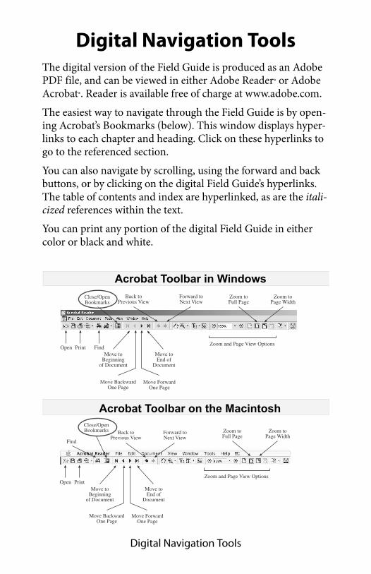
Digital Navigation Tools
Digital Navigation ToolsThe digital version of the Field Guide is produced as an Adobe PDF file, and can be viewed in either Adobe Reader® or Adobe Acrobat®. Reader is available free of charge at www.adobe.com.
The easiest way to navigate through the Field Guide is by open-ing Acrobat’s Bookmarks (below). This window displays hyper-links to each chapter and heading. Click on these hyperlinks to go to the referenced section.
You can also navigate by scrolling, using the forward and back buttons, or by clicking on the digital Field Guide’s hyperlinks. The table of contents and index are hyperlinked, as are the itali-cized references within the text.
You can print any portion of the digital Field Guide in either color or black and white.
Open Print
Find
Move toBeginning
of Document
Move toEnd of
Document
Move BackwardOne Page
Move ForwardOne Page
Back toPrevious View
Forward toNext View
Zoom and Page View Options
Zoom toFull Page
Zoom toPage Width
Close/OpenBookmarks
Open Print FindMove to
Beginningof Document
Move toEnd of
Document
Move BackwardOne Page
Move ForwardOne Page
Back toPrevious View
Forward toNext View
Zoom and Page View Options
Zoom toFull Page
Zoom toPage Width
Close/OpenBookmarks
Acrobat Toolbar in Windows
Acrobat Toolbar on the Macintosh