we2108 - cein
TRANSCRIPT

WE2108S
WE2108M
WE2108
A1632-1.0 en
Scale electronic unit(NAWI)
WE2108...(P83...P85)
Reference Manual


3WE2108
HBMA1632-1.0 en
Content Page
Safety instructions 7 . . . . . . . . . . . . . . . . . . . . . . . . . . . . . . . . . . . . . . . . . . . . .
1 Typographic Conventions 11 . . . . . . . . . . . . . . . . . . . . . . . . . . . . . . .
2 Commissioning 12 . . . . . . . . . . . . . . . . . . . . . . . . . . . . . . . . . . . . . . . .
2.1 Notes on cabling 12 . . . . . . . . . . . . . . . . . . . . . . . . . . . . . . . . . . . . . . . .
3 Short description 13 . . . . . . . . . . . . . . . . . . . . . . . . . . . . . . . . . . . . . . .
3.1 Scope of supply 13 . . . . . . . . . . . . . . . . . . . . . . . . . . . . . . . . . . . . . . . . .
3.1.1 WE2108 unit view 14 . . . . . . . . . . . . . . . . . . . . . . . . . . . . . . . . . . . . . . . 3.1.2 Operating elements 14 . . . . . . . . . . . . . . . . . . . . . . . . . . . . . . . . . . . . . . 3.1.3 Display 15 . . . . . . . . . . . . . . . . . . . . . . . . . . . . . . . . . . . . . . . . . . . . . . . . . 3.2 Connections 16 . . . . . . . . . . . . . . . . . . . . . . . . . . . . . . . . . . . . . . . . . . . .
3.2.1 Cable entry 17 . . . . . . . . . . . . . . . . . . . . . . . . . . . . . . . . . . . . . . . . . . . . . 3.2.2 Preparation of the cables 17 . . . . . . . . . . . . . . . . . . . . . . . . . . . . . . . . . 3.2.3 Load cell connection 17 . . . . . . . . . . . . . . . . . . . . . . . . . . . . . . . . . . . . . 3.2.4 Process Outputs 18 . . . . . . . . . . . . . . . . . . . . . . . . . . . . . . . . . . . . . . . . 3.2.5 WE2108 operating voltage 18 . . . . . . . . . . . . . . . . . . . . . . . . . . . . . . . . 3.2.6 Process Inputs 18 . . . . . . . . . . . . . . . . . . . . . . . . . . . . . . . . . . . . . . . . . . 3.2.7 RS−232 interface (only RS−232 versions) 19 . . . . . . . . . . . . . . . . . . 3.2.8 RS−485 interface (only RS−485 versions) 19 . . . . . . . . . . . . . . . . . . 3.2.9 Remarks 19 . . . . . . . . . . . . . . . . . . . . . . . . . . . . . . . . . . . . . . . . . . . . . . .
4 Installation 20 . . . . . . . . . . . . . . . . . . . . . . . . . . . . . . . . . . . . . . . . . . . . .
4.1 Wall mounting (WE2108 in a plastic housing) 20 . . . . . . . . . . . . . . . .
4.2 Mounting on a stand (WE2108 in a plastic housing) 21 . . . . . . . . . .
4.3 Use as desktop unit (WE2108 in a plastic housing) 22 . . . . . . . . . . .
4.4 Wall mounting / desktop unit
(WE2108S in a stainless steel housing) 22 . . . . . . . . . . . . . . . . . . . .
4.5 Control panel assembly (WE2108M in a stainless steel housing) 22
4.6 Sealing / calibration ability 23 . . . . . . . . . . . . . . . . . . . . . . . . . . . . . . . .
4.7 Information on achievable type of protection 23 . . . . . . . . . . . . . . . .
5 Operation 24 . . . . . . . . . . . . . . . . . . . . . . . . . . . . . . . . . . . . . . . . . . . . . .

4 WE2108
HBM A1632-1.0 en
5.1 Basic functions 25 . . . . . . . . . . . . . . . . . . . . . . . . . . . . . . . . . . . . . . . . . .
5.1.1 Switching on and off 25 . . . . . . . . . . . . . . . . . . . . . . . . . . . . . . . . . . . . . 5.1.2 Zeroing 25 . . . . . . . . . . . . . . . . . . . . . . . . . . . . . . . . . . . . . . . . . . . . . . . . 5.1.3 Taring 26 . . . . . . . . . . . . . . . . . . . . . . . . . . . . . . . . . . . . . . . . . . . . . . . . . . 5.1.4 Gross/Net 26 . . . . . . . . . . . . . . . . . . . . . . . . . . . . . . . . . . . . . . . . . . . . . . 5.1.5 Printing 26 . . . . . . . . . . . . . . . . . . . . . . . . . . . . . . . . . . . . . . . . . . . . . . . . 5.1.6 Preset tare 26 . . . . . . . . . . . . . . . . . . . . . . . . . . . . . . . . . . . . . . . . . . . . . 5.1.7 Display lighting 27 . . . . . . . . . . . . . . . . . . . . . . . . . . . . . . . . . . . . . . . . . 5.1.8 External operating elements 27 . . . . . . . . . . . . . . . . . . . . . . . . . . . . . . 5.1.9 Counting scale 27 . . . . . . . . . . . . . . . . . . . . . . . . . . . . . . . . . . . . . . . . . . 5.1.10 Parameter setting 28 . . . . . . . . . . . . . . . . . . . . . . . . . . . . . . . . . . . . . . . 5.1.11 Error displays 29 . . . . . . . . . . . . . . . . . . . . . . . . . . . . . . . . . . . . . . . . . . 5.1.12 Stillstand 29 . . . . . . . . . . . . . . . . . . . . . . . . . . . . . . . . . . . . . . . . . . . . . . . 5.2 Menu operation 30 . . . . . . . . . . . . . . . . . . . . . . . . . . . . . . . . . . . . . . . . .
5.2.1 Menu Overview 30 . . . . . . . . . . . . . . . . . . . . . . . . . . . . . . . . . . . . . . . . . 5.2.2 Example: Setting the parameter ”CAP 1” 32 . . . . . . . . . . . . . . . . . . . 5.2.3 Complete menu structure 33 . . . . . . . . . . . . . . . . . . . . . . . . . . . . . . . . 5.3 Explanations for the settings 39 . . . . . . . . . . . . . . . . . . . . . . . . . . . . . .
5.3.1 Display limits 39 . . . . . . . . . . . . . . . . . . . . . . . . . . . . . . . . . . . . . . . . . . . . 5.3.2 Tare value 39 . . . . . . . . . . . . . . . . . . . . . . . . . . . . . . . . . . . . . . . . . . . . . . 5.3.3 Standstill criterion 41 . . . . . . . . . . . . . . . . . . . . . . . . . . . . . . . . . . . . . . .
6 Calibration 42 . . . . . . . . . . . . . . . . . . . . . . . . . . . . . . . . . . . . . . . . . . . . .
6.1 Quick start without special functions 42 . . . . . . . . . . . . . . . . . . . . . . .
6.1.1 Setting to the nominal data of the scale 42 . . . . . . . . . . . . . . . . . . . . . 6.1.2 Calibration (standard method) 42 . . . . . . . . . . . . . . . . . . . . . . . . . . . . . 6.1.3 Part load calibration 43 . . . . . . . . . . . . . . . . . . . . . . . . . . . . . . . . . . . . . . 6.1.4 Setting for legal for trade 43 . . . . . . . . . . . . . . . . . . . . . . . . . . . . . . . . . 6.2 Special applications 44 . . . . . . . . . . . . . . . . . . . . . . . . . . . . . . . . . . . . . .
6.3 Calibration with linearization 45 . . . . . . . . . . . . . . . . . . . . . . . . . . . . . .
6.3.1 Selection of the calibration method with the ”Lin” parameter 45 . . . 6.3.2 Calibration steps for linearization (3 or 4 points) 45 . . . . . . . . . . . . . 6.4 Direct entry of the characteristic values 47 . . . . . . . . . . . . . . . . . . . . .
6.4.1 Calibrating with calculated values 48 . . . . . . . . . . . . . . . . . . . . . . . . . . 6.5 Influence of the geographical installation site 49 . . . . . . . . . . . . . . . .

5WE2108
HBMA1632-1.0 en
6.6 Access authorization 50 . . . . . . . . . . . . . . . . . . . . . . . . . . . . . . . . . . . . .
6.6.1 Pushbutton lock 51 . . . . . . . . . . . . . . . . . . . . . . . . . . . . . . . . . . . . . . . . . 6.7 Selection of suitable load cells 51 . . . . . . . . . . . . . . . . . . . . . . . . . . . .
6.7.1 Division number: 51 . . . . . . . . . . . . . . . . . . . . . . . . . . . . . . . . . . . . . . . . 6.7.2 Supply voltage and measuring signal: 51 . . . . . . . . . . . . . . . . . . . . . . 6.7.3 Dead load and nominal value: 52 . . . . . . . . . . . . . . . . . . . . . . . . . . . . .
7 Further functions 53 . . . . . . . . . . . . . . . . . . . . . . . . . . . . . . . . . . . . . . .
7.1 Filtering 53 . . . . . . . . . . . . . . . . . . . . . . . . . . . . . . . . . . . . . . . . . . . . . . . .
7.1.1 Filter and standstill 53 . . . . . . . . . . . . . . . . . . . . . . . . . . . . . . . . . . . . . . . 7.1.2 Special filter for animal scales 53 . . . . . . . . . . . . . . . . . . . . . . . . . . . . . 7.2 Limit outputs 54 . . . . . . . . . . . . . . . . . . . . . . . . . . . . . . . . . . . . . . . . . . . .
7.3 Inputs 55 . . . . . . . . . . . . . . . . . . . . . . . . . . . . . . . . . . . . . . . . . . . . . . . . . .
7.4 Printing function 57 . . . . . . . . . . . . . . . . . . . . . . . . . . . . . . . . . . . . . . . . .
7.5 Formatting of the printing output 58 . . . . . . . . . . . . . . . . . . . . . . . . . . .
7.5.1 Example 59 . . . . . . . . . . . . . . . . . . . . . . . . . . . . . . . . . . . . . . . . . . . . . . . 7.6 Setting the time 59 . . . . . . . . . . . . . . . . . . . . . . . . . . . . . . . . . . . . . . . . .
7.7 Summing function 59 . . . . . . . . . . . . . . . . . . . . . . . . . . . . . . . . . . . . . . .
7.7.1 Overview 59 . . . . . . . . . . . . . . . . . . . . . . . . . . . . . . . . . . . . . . . . . . . . . . . 7.7.2 Functions in the menu Add (new) 60 . . . . . . . . . . . . . . . . . . . . . . . . . . 7.7.3 Permitted range 60 . . . . . . . . . . . . . . . . . . . . . . . . . . . . . . . . . . . . . . . . . 7.7.4 Deletion of the sums 61 . . . . . . . . . . . . . . . . . . . . . . . . . . . . . . . . . . . . . 7.7.5 Summing function during counting scale operation 61 . . . . . . . . . . . 7.7.6 Print 62 . . . . . . . . . . . . . . . . . . . . . . . . . . . . . . . . . . . . . . . . . . . . . . . . . . . 7.8 Interface for large display (second display) 63 . . . . . . . . . . . . . . . . . .
8 Troubleshooting 64 . . . . . . . . . . . . . . . . . . . . . . . . . . . . . . . . . . . . . . . .
9 Specifications 66 . . . . . . . . . . . . . . . . . . . . . . . . . . . . . . . . . . . . . . . . . .
9.1 Specifications WE2108 in ABS−housing 66 . . . . . . . . . . . . . . . . . . . .
9.2 Dimensions WE2108 in ABS−housing 67 . . . . . . . . . . . . . . . . . . . . . .
9.3 Specifications WE2108S/WE2108M in steel−housing 68 . . . . . . . . .
9.4 Dimensions WE2108S/WE2108M in steel−housing 69 . . . . . . . . . .

6 WE2108
HBM A1632-1.0 en

7WE2108
HBMA1632-1.0 en
Safety instructions
In cases where a breakage would cause injury to persons or damage toequipment, the user must take appropriate safety measures (such as fall pro-tection, overload protection, etc.). For safe and trouble−free operation, weig-hing modules must not only be correctly transported, stored, sited and instal-led but must also be carefully operated and maintained.
It is essential to comply with the relevant accident prevention regulations. Inparticular you should take into account the limit loads quoted in the specifica-tions.
Functional overview
The scale electronic unit WE2108 is a measuring amplifier for connection tocommercially available strain gauge load cells or scales. The load cell signalis amplified and digitally converted, all further processing steps are performeddigitally in a microprocessor.
The electronic unit is set and parameterized via keyboard or interface. Thesetup program WE2108Panel serves for this purpose. It is contained togetherwith this documentation on the HBM CD−ROM with the Order No. 1−WE2108/DOC.
Use in accordance with the regulations
The scale electronic unit WE2108 is to be used exclusively as component of anon−automatic scale. Any use extending beyond this is considered to be notas intended.
In the case of legal for trade use, the national legal and safety regulationsmust be complied with.
General dangers due to non−observance of the safety instructions
• In the normal case the product causes no dangers, provided the notes andinstructions for configuring, installation, operation as intended and mainte-nance are complied with.
• The safety and accident prevention regulations applicable corresponding tothe application must be observed without fail.
• Installation and commissioning may be performed exclusively by qualifiedpersonnel.
• Avoid the penetration of dirt and moisture into the interior of the unit whenconnecting the cables.
• When connecting the cables take measures against electrostatic dischar-ges which can damage the electronic unit.

8 WE2108
HBM A1632-1.0 en
• An extra low voltage (10 − 35 V) with safe isolation from the mains is requi-red for the power supply of the unit.
• When connecting additional devices, the safety regulations according toEN610101) must be complied with.
• Observe the maximum voltage level when connecting external control sy-stems to the process input and process outputs of the WE2108.
• The ground connections of the supply, of the process inputs and processoutputs, of the interface and the shield of the load cell cable are connectedwith one another in the unit. In the case of potential differences of the devi-ces to be connected, isolate the signals in a suitable manner (e.g. by opto-coupler).
• Shielded cables are required for all connections, except for power supply.The shield must be connected flatly with ground at both ends.
• The use of unscreened voltage supply cables is permissible only for cableswith a length of up to 30 m max., which are laid within a building. In thecase of greater cable lengths, or installation outside buildings, a screenedcable must be used. In order to compensate for potential differences, themetal housing of WE2108M / WE2108S has to be connected via a low oh-mic compensation conductor with the scale components as well as with theground potential of the connected units. This is not necessary if a potentialdifference of 35 V is not exceeded.In the unit, the reference ground (GND) for all signals and the supply vol-tage is connected directly to the cable screen connection, but not to thehousing.
• The front foil is manufactured from high quality materials and offers a ser-vice life appropriate for the external conditions. The keys may be operatedonly by hand, under no circumstances may pointed objects be used topress the keys.
!) ”Safety regulations for electrical measuring, control and laboratory equipment
Residual dangers
The scope of supply and performance of the scale electronic unit covers onlya small area of weighing technology. In addition, equipment planners, instal-lers and operators should plan, implement and respond to the safety enginee-ring considerations of weighing technology in such a way as to minimise resi-dual dangers. Prevailing regulations must be complied with at all times. Theremust be reference to the residual dangers connected with weighing techno-logy.

9WE2108
HBMA1632-1.0 en
In these mounting instructions residual dangers are pointed out using the fol-lowing symbols:
Symbol: DANGER
Meaning: Highest level of danger
Warns of a directly dangerous situation in which failure to comply with safetyrequirements will lead to death or serious physical injury.
Symbol: WARNING
Meaning: Possibly dangerous situation
Warns of a potentially dangerous situation in which failure to comply with sa-fety requirements can lead to death or serious physical injury.
Symbol: ATTENTION
Meaning: Possibly dangerous situation
Warns of a potentially dangerous situation in which failure to comply with sa-fety requirements could lead to damage to property, slight or moderate physi-cal injury.
Symbols indicating application notes and useful information:
Symbol: NOTERefers to the fact that important information is being given about the productor its use.
Symbol:
Meaning: CE mark
The CE mark signals a guarantee by the manufacturer that his product meetsthe requirements of the relevant EC directives. You’ll find the Declaration ofconformity in the up-to-date version of HBMdoc, available at www.hbm.com :
• Choose your country
• SUPPORT
• Documentation

10 WE2108
HBM A1632-1.0 en
Environmental conditions
In the context of your application, please note that all materials which releasechlorine ions will attack all grades of stainless steel and their welding seams.In such cases the operator must take appropriate safety measures.
Prohibition of own conversions and modifications
The scale electronic unit must not be modified from the design or safety engi-neering point of view except with our express agreement. Any modificationshall exclude all liability on our part for any damage resulting therefrom.
Qualified personnel
This weighing electronic is only to be installed by qualified personnel strictly inaccordance with the technical data and with the safety rules and regulationswhich follow. It is also essential to observe the appropriate legal and safety re-gulations for the application concerned. The same applies to the use of acces-sories.
Qualified personnel means persons entrusted with the installation, fitting,commissioning and operation of the product who possess the appropriatequalifications for their function.
Maintenance and cleaning
The WE2108 is maintenance−free. Observe the following points when clea-ning the housing:
• Separate the connection to the power supply before cleaning.
• Clean the housing with a soft, slightly moistened (not wet!) cloth. Under nocircumstances may you use cleaners containing scouring agents or sol-vents, since these can attack the front panel lettering and the display!

11WE2108
HBMA1632-1.0 en
1 Typographic Conventions
The present Reference Manual provides detailed information on the operationas well as on the setting possibilities of the WE2108.
For more clarity the following formats are used in this document:
Meaning ExamplesKey ENTER
UPCENEXT
Menu, Sub−Menu InFO
CAL or
FunParameter ”CAL−1”
”LOAd1””unit””Point”
Display DonEBuSYErr44

12 WE2108
HBM A1632-1.0 en
2 Commissioning
The permissible supply voltage for the WE2108 is in the range from+10...35 V DC and must be filtered sufficiently (rms value less residual ripple> 10 V).
As an accessory component, a power supply unit 100 ... 240 V is available(HBM order no. 1−AC/DC15V/550mA).
With correct connection with shielded cables the WE2108 corresponds to therelevant European standards and bears the CE mark.
2.1 Notes on cabling
The use of unscreened voltage supply cables is permissible only for cableswith a length of up to 30 m max., which are laid within a building. In the caseof greater cable lengths, or installation outside buildings, a screened cablemust be used.
In order to compensate for potential differences, the metal housing ofWE2108s and WE2108M has to be connected via a low ohmic compensationconductor with the scale components as well as with the ground potential ofthe connected units. This is not necessary if a potential difference of 35 V isnot exceeded.
In the unit, the reference ground (GND) for all signals and the supply voltageis connected directly to the cable screen connection, but not to the housing.
13WE2108
HBMA1632-1.0 en
3 Short description
3.1 Scope of supply
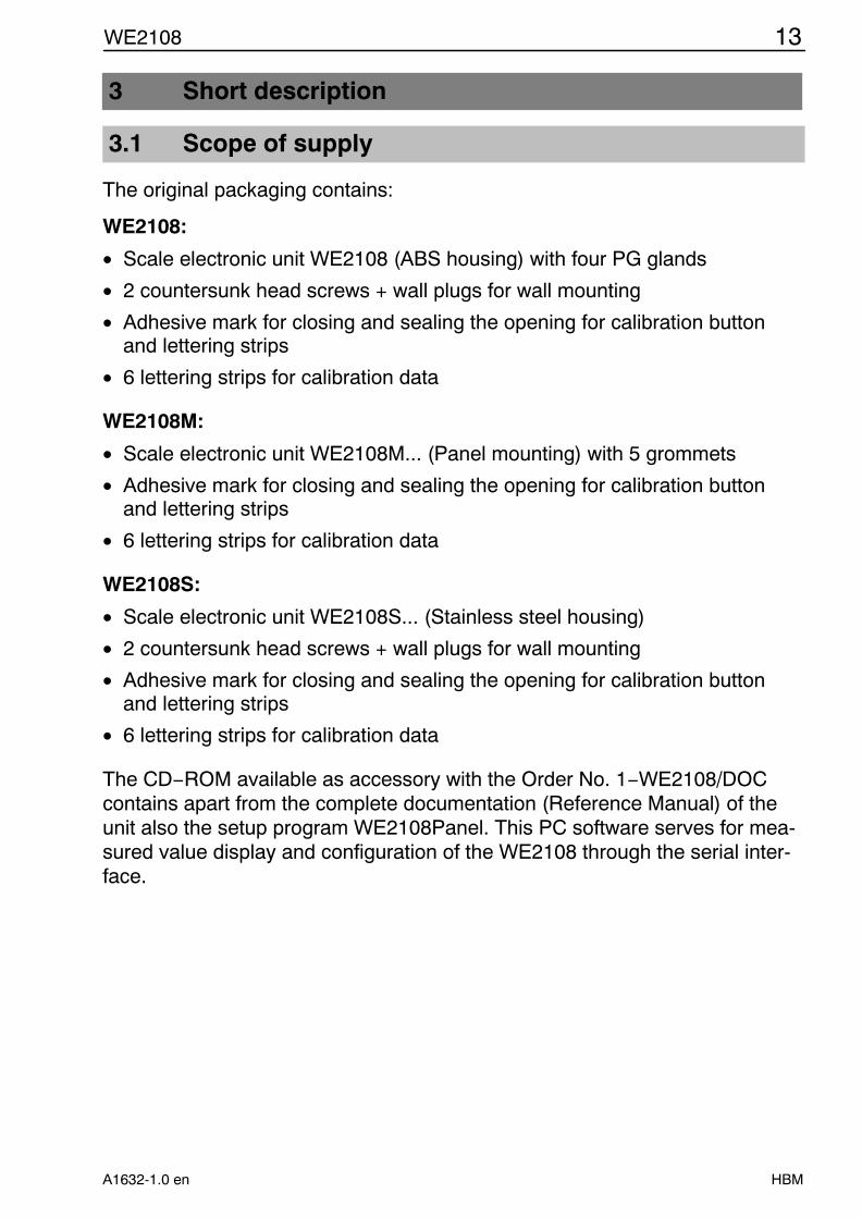
The original packaging contains:
WE2108:
• Scale electronic unit WE2108 (ABS housing) with four PG glands
• 2 countersunk head screws + wall plugs for wall mounting
• Adhesive mark for closing and sealing the opening for calibration buttonand lettering strips
• 6 lettering strips for calibration data
WE2108M:
• Scale electronic unit WE2108M... (Panel mounting) with 5 grommets
• Adhesive mark for closing and sealing the opening for calibration buttonand lettering strips
• 6 lettering strips for calibration data
WE2108S:
• Scale electronic unit WE2108S... (Stainless steel housing)
• 2 countersunk head screws + wall plugs for wall mounting
• Adhesive mark for closing and sealing the opening for calibration buttonand lettering strips
• 6 lettering strips for calibration data
The CD−ROM available as accessory with the Order No. 1−WE2108/DOCcontains apart from the complete documentation (Reference Manual) of theunit also the setup program WE2108Panel. This PC software serves for mea-sured value display and configuration of the WE2108 through the serial inter-face.

14 WE2108
HBM A1632-1.0 en
3.1.1 WE2108 unit view
The front of the WE2108 consists of the following elements:
ENTER UP
CE NEXT
WE2108
1.
3.
4.
2.0
G/N T
MENU
1. Display window with 5−digit numerical display and special symbols.
2. Keys for scale and menu functions.
3. Concealed button for access to the calibration menu. The button is accessi-ble with a pointed object (with the mark removed). The opening must beclosed after calibration with the enclosed adhesive mark or in the case of alegal for trade application with the official calibration mark. In operation thecalibration of the unit is protected and can be changed only after actuatingthis button.Please also refer to Sections 4.7 ”Information on achievable type of protec-tion” and 6.6 ”Access authorization”.
4. Viewing window for inserting a lettering strip (for calibration data, unit nameetc.).
The PG glands resp. grommets for the connection cables are located on theback of the unit.
3.1.2 Operating elements
Each of the four keys has a basic function for scale operation which is indica-ted on the key with a large symbol.
• Key 0 = Zeroing the display
• Key = Printing the display measured value / or summing function
• Key G/N = Switching over between gross and net display
• Key T = Taring and switching over into net display

15WE2108
HBMA1632-1.0 en
The inscriptions above the keys state the second function of the keys duringparameter input (menu guidance).
Activating the functions
MENU : simultaneously pressing of ENTER UP
(Counting scale): simultaneously pressing of CE NEXT
• Concealed button for access to the calibration menu (see WE2108 unitview).
3.1.3 Display
The display consists of the following elements:
• 5−digit numerical display with decimal points for the weight valueand for menu guidance in the parameter input.
• Symbol (= Battery): appears if the supply voltage is inadmissibly low.
• Symbols 1 and 2.: Their meaning depends upon the scale type.
One−range scale: Symbol shows exceeding the set limit 1 or 2.
Two−range scale: Symbol shows the range at present valid.
The symbols have a further special function during parameter setting (seeSection 5.2.1 ”Menu Overview”)
• Symbol Hold : only for filter 8 (see Section 6.1.2 ”Special filter for animalscales”)
• Symbol.Tare.: appears on display of the net value (simultaneously withNet).
• Symbol "0A (”exact zero”): indicates that the measured value is in the rangeof ¼d.
• Symbol.Net : appears on display of the net value.
• Symbol PT.(Preset Tare): appears if a stored manual tare value is used.
• Symbols g, kg, t, Lb : indicate the valid dimensional unit.

16 WE2108
HBM A1632-1.0 en
3.2 Connections
The load cell and all control and supply cables are connected by means ofscrew terminals inside the housing. The terminals are equipped with wire pro-tection, the use of connector sleeves is recommended especially for the loadcell cables.
The connection terminals are identified on the PC board with short text ornumbers.
NOTEAll ground connections are connected with one another on the PC board!
1.2.3.4.5.6.
Pout3GNDPout2GNDPout1GND
+DCGNDPin1GNDPin2GND
GNDTa TxDTb DTR Data Terminal ReadyRa RxDRbGND
Load cell connection
Process outputs
Process inputs
Supply
Interface
Sense +Sense −Signal +Signal −Excitation +Excitation −
not usedGroundProcess output 2GroundProcess output 1Ground
Supply voltageGroundProcess input 1GroundProcess input 2Ground
Ground
Groundnot used
Data output to ext. unit
Data input from ext. unit
Abb.3.1: Position of the connections (open housing, rear view)

17WE2108
HBMA1632-1.0 en
3.2.1 Cable entry
Four PG glands are provided in the back part of the housing for the sealed en-try of the cables. They enable round cables with a diameter of 5 to 7 mm to beused. The PG glands serve solely for sealing and strain relief. The shield ofthe cable must therefore not be contacted to the PG gland (as in other HBMunits), but to the screw clips in front of the connection terminals.
This also applies to the versions in a steel housing (WE2108M /WE2108S) and is essential for the EMC characteristics of the units.
To minimize EMC problems, the individual wires should be as short as possi-ble from the end of the shield up to the terminal. Therefore avoid cross−con-nections, e.g. from the interface cable to a switching input, and use instead ofthis separate cables corresponding to the terminal arrangement. A commoncable should be used for supply and switching inputs.
3.2.2 Preparation of the cables
1. Remove the outer sheath to around 20 mm.
2. Shorten the shield braiding to 5 mm andfold over to the back.
3. If necessary remove the inner sheath.
4. Strip wire ends to approx. 5 mm.
5 5Shield
20
5. Run cable through the PG gland.
6. Push cable under the connecting clip and screw this down so that the areaof the folded over shield is clamped firmly.
7. Connect wires to the terminals.
3.2.3 Load cell connection
Terminal PC board legend Function Funktion1 1. Sense + Fühlerleitung +2 −− Sense − Fühlerleitung −3 −− Signal + Messsignal +4 −− Signal − Messsignal −5 −− Excitation + Brückenspeisespannung +6 6. Excitation − Brückenspeisespannung −

18 WE2108
HBM A1632-1.0 en
3.2.4 Process Outputs
Terminal PC board legend Function Example of connection7 Pout3 not used
Pout3GNDPout2GNDPout1GND
Sup
ply
for
switc
hed
load
s
+
−
8 GND Ground9 Pout2 Process output 2!)
10 GND Ground11 Pout1 Process output 1!)
12 GND Ground!) open−collector to ground, (external) Umax = 45 V, Imax = 200 mA typ. (electronically protected). When con-
necting magnetic articles (e.g. relays), a free wheeling diode must be connected parallel to the coil.
3.2.5 WE2108 operating voltage
Terminal PC board legend Function Remarks13 +DC Operating voltage +10−35 V DC@)
14 GND Ground@) The supply voltage must be filtered sufficiently (rms value less residual ripple > 10V).
3.2.6 Process Inputs
Terminal PC board legend Function Example of connection15 Pin1 Process input 1#) +DC
GNDPin1GNDPin2GND
16 GND Ground
17 Pin2 Process input 2#)
18 GND Ground
#) Actuate by switching to ground, max. voltage 35 V.

19WE2108
HBMA1632-1.0 en
3.2.7 RS−232 interface (only RS−232 versions)
Terminal PC board legend Function Standard assignmentof external unit
RS−232 DB25 RS−232 DB919 GND Ground Pin7 Pin520 Ta TxD Data output to the
external unit (TxD)RxD, Pin3 RxD, Pin2
21 Tb DTR do not connect !22 Ra RxD Data input from the
external unit (RxD)TxD, Pin2 TxD, Pin3
23 Rb do not connect !24 GND Ground
TxD TxD
RxD RxD
GND GND
For the communication with an external device its TxD line must beconnected with RxD of the WE2108 and vice versa.
3.2.8 RS−485 interface (only RS−485 versions)
See Reference Manual Part 2 (Description of the commands for computer in-tegration)
3.2.9 Remarks
For all housing variants, the reference ground (GND) for all signals andthe supply voltage is connected directly to the cable screen connectionin the unit, but not to the housing.
The metal housing of WE2108M / WE2108S is not connected to referenceground. In order to compensate for potential differences, the metal hou-sing of WE2108s and WE2108M has to be connected via a low ohmiccompensation conductor with the scale components as well as with theground potential of the connected units. This is not necessary if a po-tential difference of 35 V is not exceeded.
Up to four load cells of 350 ohms ( 87 ohms burden) can be connected tothe WE2108. HBM offers junction boxes of the types VKK1−4 or VKK2−6 forconnecting the cables as well as for corner balancing (”corner load adjust-ment”) for scales with several load cells.
Only high quality, flexible cables with shield may be used for connecting theload cells. HBM recommends the use of these cables for all connections ofthe WE2108. For connection satisfying EMC requirements (EMC = electroma-gnetic compatibility), the cable shield of all cables must have a low−resistancecontact to the unit ground, for this purpose the shield must be stripped to ap-prox. 5 mm and the cable must be fastened with the strain relief clips.

20 WE2108
HBM A1632-1.0 en
Electrical and magnetic fields frequently cause coupling of interference volta-ges into the measuring circuit. Use only shielded, low−capacitance measuringcables (measuring cables from HBM fulfil these conditions). Do not run themeasuring cables parallel to power current and control cables. If this is notpossible, protect the measuring cable (e.g. by steel conduits). Avoid strayfields of transformers, motors and contactors.
The WE2108 is designed for six−wire connection of the load cell. When con-necting four−wire load cells, in each case connect the terminals 1 with 5 and2 with 6 using cable jumpers. In the case of faulty load cell connection or lea-ving the sensor lines open (terminal 1 and 2) the message Err44 appears onthe display.
4 Installation
4.1 Wall mounting (WE2108 in a plastic housing)
The housing design of the WE2108 permits wall mounting without visiblemounting elements. For this purpose the finally assembled unit must be setagainst the wall and snapped in as in Abb. 4.2 Since the wall screws are notvisible in this case, the mounting base of the housing has lead−in bevels fortactile determination of the screw position.
Two screws are required (countersunk head screws in the scope of supply) ata spacing of 86 mm. In this type of mounting the housing is secured againstlifting off by forces occurring in everyday use by the screws snapping in. A prerequisite is the use of one of the following types of screw:
• Cheese−head screws, shank without thread with 4 mm diameter.
• Countersunk head screws, diameter under the head max. 3.5 mm. Formounting with wall plugs, 4.0 x 50 mm chipboard screws, the thread ofwhich ends approx. 10 mm under the head, for instance, are suitable.
Please observe the correct distance of the screw heads from the wall (in mm):
or
86
8 9
left + rightleft right
7
Wall
Abb. 4.1: Distances

21WE2108
HBMA1632-1.0 en
Screws
CLICK
Abb. 4.2: Movement sequence of the wall mounting
4.2 Mounting on a stand (WE2108 in a plastic housing)
Mounting on a stand is possible for free standing scales. This must have aplate for four holes according to Abb. 4.3 for fastening the WE2108. With cor-responding design, a concealed cable run inside the stand is possible. Forbetter stability the plate should fit in the space between the rubber feet, orthese should be removed.
Opening for cables
Abb. 4.3: Mounting on a stand

22 WE2108
HBM A1632-1.0 en
The unit is mounted in the following steps:
1. Remove the mounting base from the back of the housing after looseningtwo screws.
2. Fasten the mounting base to the stand plate with four screws with a diame-ter of 4 mm.
3. Run cables through the PG glands and connect to the electronic unit.
4. Close the housing halves and connect with two screws. In this case pull thecables still a little out from the PG glands.
5. Fasten the closed housing to the mounting base with two screws. In thiscase possibly run the cables into the inside of the stand tube.
4.3 Use as desktop unit (WE2108 in a plastic housing)
The WE2108 is provided with four rubber feet for installing on horizontal surfa-ces. These generally guarantee safe standing and prevent slipping awaywhen operating the keys.
Moreover fastening in the same way as in wall mounting is possible. If themounting surface is accessible from below, the holes for stand mounting canalso be used. If the feet remain on the unit in this case, take care that themounting base is not stressed by tightening the screws too firmly.
For inclination of the operating area towards the user, the mounting base mustbe installed with the curved part upwards.
4.4 Wall mounting / desktop unit (WE2108S in a stainless steel
housing)
The unit is wall−mounted by means of two bolts, or it can be used as a desk-top unit. See ”Dimensions WE2108S / WE2108M (Stainless steel housing)”on page 72.
4.5 Control panel assembly (WE2108M in a stainless steel housing)
The unit is assembled into a control panel by means of six bolts. See ”Dimen-sions WE2108S / WE2108M (Stainless steel housing)” on page 72.
WARNING
The protection class IP65 for type WE2108M only applies to the front!

23WE2108
HBMA1632-1.0 en
4.6 Sealing / calibration ability
According to the scale application, the scale electronic unit must be labelledand sealed. Different lettering strips are enclosed for use as non−automaticscale of class III and IIII.
The following data must be stated on the lettering strip as a minimum:
Max Maximum load of the scaleMin Minimum load of the scalee Scale intervalType Name of the scaleS.N. Individual serial number of the scale
In the case of legal for trade scales, the calibration must be performed accor-ding to the applicable laws by a notified body. The seal marks and calibrationmarks must be fastened according to the approval.
4.7 Information on achievable type of protection
Observe that the tightness of the housing is guaranteed only if:
• The opening for calibration button and lettering strip on the front of the unitis closed (by a calibration mark or with the enclosed adhesive mark).
• All PG glands are screwed tight and round cables with suitable diameter areused.
• PG glands which are not used are closed with the enclosed blind plugs.
• The housing halves are assembled correctly.

24 WE2108
HBM A1632-1.0 en
5 Operation
All unit functions can be controlled in one or several of the following ways:
• Operating front with 4 short stroke keys
• Two programmable switching inputs
• Coupling an external computer through the serial interface
The keyboard controls directly the essential scale functions (gross/netG/N , taring T , zeroing 0 and printing ). A menu is called
up for calibration and further unit settings. During parameter input up to exitingthe menu no weight value is displayed. The currently measured value, howe-ver, affects the limit value outputs in this operating mode as well. When con-trolling via computer commands, the measurement runs on without interrup-tion as a rule. Exceptions are the transient condition after filter switch−overand the non−volatile storage in the EEPROM.
When the electronic unit is switched on, all segments of the display are activa-ted initially for 2 seconds (only in legal for trade applications). The check co-unter is then displayed. Automatic zeroing occurs during this time if this func-tion is activated.
NOTEThe WE2108 does not check whether the performed settings are permis-sible according to OIML R76!

25WE2108
HBMA1632-1.0 en
5.1 Basic functions
5.1.1 Switching on and off
The unit is switched on after the supply voltage is applied. To switch off pro-ceed as follows:
Unit switched off 1)
ENTER UP
MENUCE NEXT
G/N
0
T
WE2108
kg
Main Menu
ENTER+UPPress simultaneously
CE
Scale Mode
ENTER
UP
(Cancel)
1
1
1) Switching back on with arbitrary key
NOTEIn the ioSEt menu (see 5.2.3 ”Complete menu structure ”) the Auto−OFFfunction can be activated (Parameter ”OFF_t”). This switches theWE2108 off automatically if no weight is applied on the unloaded scaleduring a predetermined time.
5.1.2 Zeroing ( 0 )
By pressing the 0 key with the scale unloaded, a remaining weight valueis set to zero. In this way small errors, e.g. due to soiling the scale platform,can be corrected. This zeroing is permitted only in a limited range accordingto the scale standard and is otherwise not performed by the WE2108. Use thetare function for subtracting larger loads (e.g. transport containers).

26 WE2108
HBM A1632-1.0 en
5.1.3 Taring ( T )
The current gross value is stored by pressing the T key and deductedfrom all following weight values. The displayed (net) value is therefore zero di-rectly after taring. The tare value can be read off in the InFO menu item under”tArE”. According to OIML taring is possible only at a gross value >0.
5.1.4 Gross/Net ( G/N )
Every pressing of the G/N key switches between gross and net display.When switching over to net display, the last valid tare value is reused (excep-tion see under 5.1.6 ”Preset tare”). Switching over to net is possible if thescale has already been tared.
5.1.5 Printing ( )
The just displayed weight value can be printed on a connected printer bypressing the key. The value is printed only when the measured valueis stable (”Standstill”). Different formats (e.g. weight with time or a user defi-ned text) can be selected beforehand in the parameter menu.
The key also controls the summing function (see Section 7.7).
NOTEThere is no printout if no print format is selected or the interface is oc-cupied with another function. See Section 5.2.3 ”Complete menu struc-ture”.
5.1.6 Preset tare
With the ”Preset tare” function active, the net value is formed by deducting afixed tare value. This value as well as the Preset tare ON/OFF setting is ent-ered in the parameter menu. However, the current value can continue to betared with the tare key ( T ). This value is lost when switching over to thegross display, subsequent switching over to net with the G/N key again ac-tivates the entered preset tare value.
The PT symbol in the display indicates that the net value has been formed bydeducting the preset tare value. This disappears after taring with the tare key( T ).

27WE2108
HBMA1632-1.0 en
5.1.7 Display lighting
Proceed as follows to switch the LCD background lighting on and off:
Main Menu
ENTER+UPPress simultaneously
CE
Scale Mode
1
ENTER
(Cancel)
UP (2x)
1 Light ON / OFF
ENTER UP
MENUCE NEXT
G/N
0
T
WE2108
kg
5.1.8 External operating elements
According to the configuration of the scale, the gross / net switch−over, taringand printing functions can also be operated by external switches (e.g. for ope-rating from the vehicle). The parameter menu is used for the assignment ofthe required function (see section 7.3 ”Inputs”).
5.1.9 Counting scale ( )
In use as counting scale (when weighing many parts of the same weight), thenumber of the parts placed on the scale is displayed instead of the weight.This function is not legal for trade and is available only on corresponding set-ting in the parameter menu (”tYPE” = 0 in the Func menu).
After the scale has been switched on, a weight value is indicated first. Duringswitchover to counting scale mode a reference measurement is carried out.To this end, a specific quantity is to be placed on the scale which is indicatedfor a second after the function has been activated (see below). For modifyingthe reference quantity, several preset values are shown in the menu Count(selection by means of the keys UP and NEXT, press ENTER to accept). Themenu item ”other” permits any other values to be input.

28 WE2108
HBM A1632-1.0 en
Operation:
1. (Optional): Placing a container on the scale and taring.
2. Placing the reference quantity of the parts to be counted on the scale. Thisnumber is predetermined or must be changed in the parameter menu. Thenactivate the counting scale function as follows:
Scale Mode
ENTERCE+NEXTPress simultaneously
21
1)
Counting scale
ENTER UP
MENUCE NEXT
G/N
0
T
WE2108
kg
!) To identify the active counting scale function, a ”c” appears to the left of the counting value in the display atstandstill (not for 5−digit numerical values).
3. When other quantities are placed on the scale, the new number is now dis-played. Due to the accuracy limits of the scale and possible spreads of theindividual weights (e.g. for fruit weighing) the display can deviate from theactual quantity.
4. Ending the counting scale function and switching back to weight display ispossible at any time by pressing ENTER.
5.1.10 Parameter setting
You reach the parameter menu (MENU) of the WE2108 by pressing the EEN-TER + UP keys simultaneously. Here you can set unit functions, limits, prin-ting logs etc. and calibrate the scale. It is also possible to switch the unit offmanually.
There is an explanation of the menu structure and the complete description ofall parameters in Section 5.2 ”Menu operation”.

29WE2108
HBMA1632-1.0 en
HINWEISThe major part of the parameters can also be entered through the PC−in-terface (RS−232 / RS−485). The CD−ROM available as accessory with theOrder No. 1−WE2108/DOC contains apart from the complete documenta-tion (Reference Manual) of the unit also the setup program WE2108 Pa-nel. This PC software serves for measured value display and configura-tion of the WE2108 through the serial interface.
5.1.11 Error displays
The permissible range of the display depends upon the nominal value of thescale and the set operating mode (scale standard).
The following error appears in the display if the measured value is
• above the max. display limit: (Striche oben)
• below the min. display limit: (Striche unten)(Please also refer to Section 5.3.1 ”Troubleshooting”)
Further errors are displayed as two−digit code numbers (e.g. Err44). Theyshould not occur in normal operation.
For rectification refer to Section 8 ”Troubleshooting”.
5.1.12 Stillstand
The zeroing, taring, summing and printing functions are performed only if astable value stands in the display. This is designated as standstill and is dis-played by the appearance of the unit of measurement. The standstill conditionis that the value changes maximally by a specific variation range per time unit.In the case of fluctuating (wind) loads or a very high scale resolution, possiblyno standstill is reached. In this case a more strongly damping filter or a lowerresolution must be selected in the parameter setting.
Different options for standstill indication can be selected in the menu Func,see also Section 5.3.3 .

30 WE2108
HBM A1632-1.0 en
5.2 Menu operation
5.2.1 Menu Overview
You reach the parameter menu (MENU) of the WE2108 by simultaneouslypressing the ENTER + UP keys. Here you can set unit function, limits, printinglogs etc. and calibrate the scale characteristic. For better overview the para-meters are grouped in several submenus, which can be called up using themain menu. This also offers the ”Power Off” function (see 5.1.1 ”Switching onand off”) and parameter printing (only with active printer interface). Certain pa-rameters are not accessible in every operating mode of the unit, or can onlybe read. In the case of legal for trade units, a concealed button which is ac-cessible only with the calibration mark removed must be activated for calibra-tion.
The parameter main menu consists of the following items:
Main menu itemInFO Info submenuP_tAr Preset tare valueSEtPt Limit submenuioSEt Unit setting submenuPrint Printing submenuFiL Filter submenuFunc Scale function and nominal values submenuCAL Calibration submenuFACt Factory setting submenuPrtPA Printout of the unit settingstESt Test function submenuCount Input of the reference quantityAdd Summing functionLiGht Display lighting−OFF− Power off
Basically a parameter setting runs as follows:1. Activating the (main−)MENU function by simultaneously pressing ENTER +
UP. You decide for a certain submenu in the main menu.2. The required submenu is selected with NEXT or UP and appears as short
text in the display. A small.1.on the left in the display indicates here that youare still in the main menu.
3. You reach the selected submenu with ENTER. The required parameter isselected with NEXT or UP and appears as short text in the display. Thesmall 2 on the left in the display indicates that you are in a submenu. CEswitches back to the main menu.
4. After pressing ENTER again the current numerical value of the parameter isdisplayed. The symbols 1 and 2 appear simultaneously.
5. Should the parameter not be changed, then press CE in order to reach thesubmenu again. To change the value press UP. The right number placestarts to flash at second intervals.

31WE2108
HBMA1632-1.0 en
6. Change the flashing place by pressing UP repeatedly. In the case of multi−digit values NEXT switches to the higher value digit, which can then also bechanged with UP.
7. To accept the entered value now press ENTER. The entered value is re-jected with CE and the previous value restored. In both cases the dis-play changes back to the parameter name. To change further parametersproceed as in Item 3.
8. After inputting all required parameters press CE twice in order to return tothe scale mode.
Menu structure overview
kg21
kgPT
21
kgPT
21
kgPT
21
1
1
Mainmenu
ENTER+UPPress simultaneously
1
1
NEXTUP
ENTER 2
2
2
kgPT
21
kgPT
21
UP
UP
NEXT
UP
UP
kgPT
21
Parameter changeSubmenuwith singleParameters
ENTER
CE
EN
TE
R(C
hang
e / A
ccep
t)
kgPT
UP
NEXT
NEXT...UP...
NEXTUP
NEXT...UP...
NEXTUP
CE
Example:Limit menu
Number to be setflashes
Scale Mode
CE(Cancel)
ENTER UP
MENUCE NEXT
G/N
0
T
WE2108
kg
21

32 WE2108
HBM A1632-1.0 en
5.2.2 Example: Setting the parameter ”CAP 1”
21
PTkg
21
PTkg
21
PTkg
21
NEXT...
1
Mainmenu
ENTER+UPPress simultaneously
ENTER
NEXT
UP
Parameter change
CE
CE
Scale Mode
CE(Cancel)
UP...
2 21kg
UP
UP...
ENTER
Number to be set flashes
ENTER (Change) Accept
Submenu
21
PTkg
ENTER UP
MENUCE NEXT
G/N
0
T
WE2108
kg
The major part of the parameters can be reached through the described struc-ture of main and submenu. The following functions are exceptions:
• The ”−OFF−” (Power off), ”LiGht” (Light) and ”PrtPA” (Print parameter) func-tions are performed directly from the main menu.
• The ”P_tAr” (Preset tare value) and ”Count” (Reference quantity) parame-ters can be reached without a submenu. ”Count” provides optionally for thefree input of any values or a selection from preset stages.

33WE2108
HBMA1632-1.0 en
5.2.3 Complete menu structure
”Information” submenu
CE
Para-meter
Meaning Value range Remarks
CHEC Calibrtation counter 0 ... 99999 only displayENTER tArE Current tare value 0 ... 99999 Display of the current tare
value.Change under ”P_tAr”
NEXTS_Ver Software version only display
NEXTF_nb Production number only display
UP Err Last occurring error code 0 ... 99 only displayUPOV_Ld Scale counter overload
(130% MAX)0 ... 99999 only display
P_tAr Preset tare value 0 ... 99999 Appears only with presettare function activated(Func menu)
”Limits” submenu
CE
Para-meter
Meaning Value range Remarks
ENTER
P1_Fu Limit 1 function 0: off1: limit related to gross2: limit related to net
NEXT
P1_Lo Limit output 1 logic 0: active = open, 1: active = Ground
NEXTP1_On Switch−on value 1
UP P1_OF Switch−off value 1 for setting a hysteresisUPP2_Fu Limit2 function 0: off
1: limit related to gross2: limit related to net
P2_Lo Limit output 2 logic 0: active = open, 1: active = Ground
only display
P2_On Switch−on value 2P2_OF Switch−off value 2 for setting a hysteresis

34 WE2108
HBM A1632-1.0 en
”Unit setting” submenu
CE
Para-meter
Meaning Value range Remarks
ENTER
OFF_t Time for automatic switch−off (only with un-loaded scale)
0: deactivated1...99
Time = ”OFF_t” * 20s
NEXT
UP
Fin 1 Switching input 1 function 0: no function1: taring2: print3: gross / net4: taring / gross
alternatingly
Only if input not occupied byspecial function (see ”F_InP”in the Func menu).
Fin 2 Switching input 2 function 0: no function1: taring2: print3: gross / net
Only if input not occupied byspecial function (see ”F_InP”in the Func menu).
bAud serial interface baud rate 0: 12001: 2400, 2: 48003: 9600 baud with 8N14: 12005: 24006: 48007: 9600 baud with 8E1
8 data bits, no parity, 1 stop bit
8 data bits, even parity, 1stop bit
F_Ser serial interface function 0: off1: print2: PC−connection 3: serial display
(autom. output)St_Ch Start character ASCII range
(Standard value = 00)00 → no Start character
E_Ch1 End character 1 ASCII range(Standard value = 13)
For the use of own PC programs only
E_Ch2 End character 2 ASCII range(Standard value = 10)
For the use of own PC programs only
”Print” submenuappears only if interface is set to printing (”F_SEr” = 1 in the ioSEt menu)
CE
Para-meter
Meaning Value range Remarks
ENTER
F_Prt Print function: 0: off1 ... 9: Printing logs
see Section“Printing”
SPACE Number of spaces beforeeach printed line
NEXT LnEF1 Number of blank linesbefore the printing lines
UP LnEF2 Number of blank lines afterprinting
A_nb Article number 0 ... 99999 0: ”A_nb” is not printed
hour Hours Time is required only for prin-ting function
Min MinutesdAY Day Date is required only for prin-
ting function
Mon MonthYEAr Year

35WE2108
HBMA1632-1.0 en
”Filter settings” submenu
CE
Para-meter
Meaning Value range Remarks
ENTER
NEXT
UP
F_FiL Digital filter setting(3dB – cutoff frequencyat ”Icr” = 0) 0: 13,0Hz
1: 12,5Hz2: 11,2Hz3: 07,5Hz4: 03,0Hz5: 02,5Hz6: 02,0Hz7: 01,0Hz8: Special filter for
animal scales
Mesurement / Settling timerate [s−1] [ms]0. 50 / 0901. 50 / 1002. 50 / 1103. 50 / 1204. 50 / 4005. 40 / 4756. 33 / 5507. 28 / 6258. not specif. / Signal
(variable) dependant
Icr Mean value formation 0 ... 99 The averaged values areoutput with unchanged mea-suring rate (moving averagefilter).

36 WE2108
HBM A1632-1.0 en
”Scale function” submenu (only with access authorization!)
CE
Para-meter
Meaning Value range Remarks
ENTER
LocPA Protection of the cal-ibration parameters
0: Access allowed1: Access blocked !)ENTER
F_tAr Taring function: 0: Normal1: Preset tare
NEXT
UP
unit Dimensional unit: 0: none1: g2: kg 3: t 4: lb
AutoZ Switch−on zero 0: off1:1: ±2%2:2: ±5%3: ±10%4: ±20%5: ±50%6: −5...+15%7: −2...+18%
of the nominal value
ZtrAC Automatic zero trak-king
0: off1: 0.5 d2: 1 d3: 2 d
/ sec.
StiLL Standstill monitoring 0...29see Section 5.3.3
for Filter ”F_FiL” = 8 only ”StiLL”from 1...9 meaningfull
F_InP Special functions of theswitching inputs
F_InP0123456
PIN1Fin 1tiltFin 1tiltFin 1tiltFin 1
PIN2Fin 2Fin 2PaSpPaSptiltlocklock
PaSp interlocking all calibrationparameters by switching input 2 (e.g. key switch).
lock = locking the control keys byswitch input 2.
”Fin 1”/”Fin 2” = as set in the ioSEt menu.
ALt Correction of gravityaltimeter
0 ... 99 (x100) m Relevant for calibration in changedinstallation location(see Section 6.5 ”Influence of thegeographical installation site”)
Lat gravity latitude 0 ... 90 Relevant for calibration in changedinstallation location (see Section6.5 )
trAdE Calibration mode /scale standard
0: Industrial application1: OIML: 100e..6000e2: NTEP: 100e..6000e
Point Place after decimalpoint
0 ... 4
tYPE Scale type 0: Counting scale1: One−range scale2: Two−range scale3: Two−interval scale
rES 1 Scale interval 1 in d 01 ... 50CAP 1 Scale nominal value
range 1100 ... 99999 for one−range scales
rES 2 Scale interval 2 in d 01 ... 50
CAP 2 Scale nominal valuerange 2
100 ... 99999 for two−range scales / two−intervalscales
!) Zugriff nach Betätigung des verdeckten Tasters erlaubt. (Siehe hierzu auch Abschnitte 4.7 “Hinweise zurerreichbaren Schutzart” und 6.6 ”Zugangsberechtigung”)

37WE2108
HBMA1632-1.0 en
”Calibration” submenu (see Section 6 ”Calibration”)(only with access authorization!)
Values can be changes manually or automatically measured with ENTER
CE
Para-meter
Meaning Value range Remarks
ENTER
Lin Linearization 0: off (2 Points)1: polynominal (3 points)2: polynominal (4 points)
0: Part load calibration possible
NEXT
CAL−0 Internal value, unloaded −20000...20000 (=2mV/V) Optional input orautomatic measurement
NEXT
UP
LOAd1 Display for weight 1 0 ... 99999 e.g. half nominal value in3−point calibration
UPCAL−1 Internal value for weight 1 −20000...20000 (=2mV/V) Optional input or
automatic measurementLOAd2 Display for weight 2 0 ... 99999 Blocked for ”Lin” = 0CAL−2 Internal value for weight 2 −20000...20000 (=2mV/V) Blocked for ”Lin” = 0LOAd3 Display for weight 3 0 ... 99999 Blocked for ”Lin” = 0 or 1CAL−3 Internal value for weight 3 −20000...20000 (=2mV/V) Blocked for ”Lin” = 0 or 1
Factory setting
CE
Para-meter
Meaning Value range Remarks
ENTER
dEFLt Resetting the settings (e.g.filter) to factory default
−− The scale calibration is de-leted i.e. the WE2108 is setto the factory characteristic 0 ... 2 mV/V.
Further parameters are only for service purposes
Printing Parameters
Value range RemarksPrinting the parameters with ENTER −− Appears only if the interface
is set to printing (”F_SEr” = 1in the ioSEt menu)

38 WE2108
HBM A1632-1.0 en
Test functions for Service purposes
Para-meter
Meaning Remarks
t_LCd Display−Test ENTER:Switching special segments on / offNEXT: Switch through test pattern (numbers)
00000, 12345 ,1 3 5, 2 3 , 8 , 88888, −−−−−t_IO Switching inputs / outputs
testUP: Process output 1 on / offNEXT: Process output 2 on / off
Display of the inputs: 01000 = basic state,xxx1x = Process input 1 activated, xx1xx = Process input 2 activated, x0xxx = concealed pushbutton activated
t_Ser Test of the interface ASCII characters to sent to the WE2108 (only numbers,30h..39h) are displayed in the display.UP: Output of the ASCII character 38h (number ”8”)NEXT: Output of the ASCII character 0Dh (”Carriage
return”) + 0Ah (”LineFeed”).An ”8” is displayed in the display by connecting TxD andRxD (no computer connected) and activating ”UP”, if theinterface driver and cable are not defective.
t_UtP Temperature measuringdisplay
Internal values for service purposes
t_Uin Supply voltage
t_Ubr Internal measured value 1
t_AdU Internal measured value 2 Test of the measuring signal conversion.The display is in mV/V, refreshed every 0.5 seconds.The values serve for orientation concerning the load cell utiliza-tion.
However, the values in the CAL menu should be read off forrecording the user calibration, because they are more accurate.
Reference quantity for counting scales ( )Value range Remarks
Count Reference quantity Selection 1, 5, 10, 20, 50,100 or ”other” (=Input 1 ... 99999)
Appears only for activatedcounting scale (”tYPE” = 0 inthe Func menu)

39WE2108
HBMA1632-1.0 en
Summing functions
Para-meter
Meaning Remarks
F_Add Switching the summingfunction on/off
See Section 7.7
total Indication of sum, if nec. intwo display phases for val-ues > 5 digits
t_nbr Indication of summandcounter
clr_t Deletion of sum andsummand counter
Prtno Indication of running num-ber for print output
See Section 7.4
clr_P Deletion of running num-ber
See Section 7.4
Display lightning ON / OFF
Switch light on / off with ENTER −− see 5.1.7 ”Display ligth-ning”
Switch unit off with ENTER −− see 5.1.1 ”Switching onand off”
5.3 Explanations for the settings
5.3.1 Display limits
The permissible range of the display depends upon the scale standard. Thesetting is made in the Func submenu, ”trAdE” parameter.
trAdE Scale standard lower limit upper limit0 not legal for trade −135 % nominal value 135 % of nominal value1 OIML −2 % nominal value nominal value + 9d2 NTEP −2 % nominal value 105 % of nominal value
5.3.2 Tare value
A switchover in the net display by means of the G/N −key is only possiblefor a tare value (or manual tare value) > 0.
The operation of the tare key always triggers a taring of the applied load, thatis, subsequently the tare value equals the current gross value. By means ofthe setting ”F_tAr” = 1 (menu Func, parameter−protected) a manual tare func-tion can be activated additionally. When the G/N −key is operated, the ma-nual tare value, which was input in the menu ”P_tAr” , is used instead of thetared value.
40 WE2108
HBM A1632-1.0 en
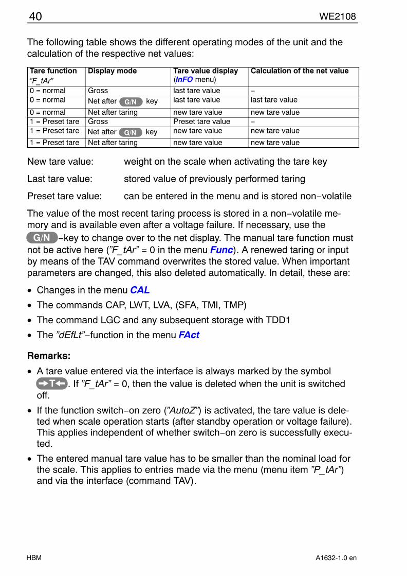
The following table shows the different operating modes of the unit and thecalculation of the respective net values:
Tare function”F_tAr”
Display mode Tare value display(InFO menu)
Calculation of the net value
0 = normal Gross last tare value −0 = normal Net after keyG/N last tare value last tare value
0 = normal Net after taring new tare value new tare value1 = Preset tare Gross Preset tare value −1 = Preset tare Net after keyG/N new tare value new tare value
1 = Preset tare Net after taring new tare value new tare value
New tare value: weight on the scale when activating the tare key
Last tare value: stored value of previously performed taring
Preset tare value: can be entered in the menu and is stored non−volatile
The value of the most recent taring process is stored in a non−volatile me-mory and is available even after a voltage failure. If necessary, use the
G/N −key to change over to the net display. The manual tare function mustnot be active here (”F_tAr” = 0 in the menu Func). A renewed taring or inputby means of the TAV command overwrites the stored value. When importantparameters are changed, this also deleted automatically. In detail, these are:
• Changes in the menu CAL
• The commands CAP, LWT, LVA, (SFA, TMI, TMP)
• The command LGC and any subsequent storage with TDD1
• The ”dEfLt”−function in the menu FAct
Remarks:
• A tare value entered via the interface is always marked by the symbolT . If ”F_tAr” = 0, then the value is deleted when the unit is switched
off.
• If the function switch−on zero (”AutoZ”) is activated, the tare value is dele-ted when scale operation starts (after standby operation or voltage failure).This applies independent of whether switch−on zero is successfully execu-ted.
• The entered manual tare value has to be smaller than the nominal load forthe scale. This applies to entries made via the menu (menu item ”P_tAr”)and via the interface (command TAV).

41WE2108
HBMA1632-1.0 en
5.3.3 Standstill criterion
The condition for a standstill indication can be set by means of the parameter”StiLL” in the menu Func. The parameter values 00 to 29 are permitted in ac-cordance with the following table
(First digit = time interval, second digit = step width).
Standstill is indicated when the measured value varies maximally by the pre-set step width within the time interval.
Parameter values (00...29):
Time interval for standstill testing1 second 0,5 seconds 0,2 seconds
any 00 10 201 d 01 11 21
dth 2 d 02 12 22
wid 3 d 03 13 23
ep w 4 d 04 14 24
step 5 d 05 15 25
ax. s 6 d 06 16 26
max 7 d 07 17 27m
8 d 08 18 289 d 09 19 29
• For specific filter settings (large ”Icr”−values), the time interval cannot besmaller than the response time of the filter. This taken into acount automati-cally, the parameter ”StiLL” will then indicate only the minimum time periodfor the standstill criterion.
• The settings 0, 10 and 20 have the effect that no standstill testing takesplace. Processes that depend on a standstill (taring, printing, summing) arealways executed.
• With an activated special filter (setting ”F_FiL” = 8 or asf8−command), thetime interval has been significantly extended when compared to the filtersettings 0..7, it depends on the parameter ”Icr”. Using the value of ”StiLL”only the step width can then be set (e.g. the settings 04, 14 and 24 are ofequal value). The standstill test is always active, the settings ”StiLL” = 00,10, or 20 are treated as ”StiLL” = 01.
• The user must set a value in accordance with the calibration regulations.

42 WE2108
HBM A1632-1.0 en
6 Calibration
The scale is calibrated by setting the user characteristic on the WE2108, i.e.the scale electronics are adapted to the actual output signals which the loadcell delivers with unloaded scale or at nominal weight. Calibration weights arerequired for this as a rule, as an alternative it is possible to enter the measu-red values if these are known.
6.1 Quick start without special functions
The following settings must be made on a new scale in any event. Furtherfunctions can be expedient according to the application and are describedstarting from section 5.2.3 ”Complete menu structure”.
6.1.1 Setting to the nominal data of the scale
Submenu Parameter Meaning ValuesFunc unit Displayed dimensional unit 0: (= no unit)
1: g
2: kg
3: t
4: lbPoint Places after the decimal
point of the displayz.B. 3 for ”6.000 kg”
rES−1 Scale intervalCAP 1 Nominal range of the scale z.B. 6000 for ”6.000 kg”
6.1.2 Calibration (standard method)
In most scale applications calibration is at two points, i.e. with the scale unloa-ded and after placing a calibration weight on the scale. Further possibilitiesare described starting from Section 6.3 ”Calibration with linearization”. Calibra-tion is performed as follows:
1. Call up the CAL menu.
2. The parameter ”Lin” has to be 0 (factory setting, check with ENTER).
3. Zero value:
• Call up the ”CAL−0” parameter, the previous calibration value is displayedwith ENTER.
• Leave the scale unloaded.
• Pressing ENTER again starts the measurement. buSY appears in the dis-play.
• When the measured value is displayed, the measurement is completed.The value is displayed in mV/V (2,0000 = 2 mV/V).
43WE2108
HBMA1632-1.0 en
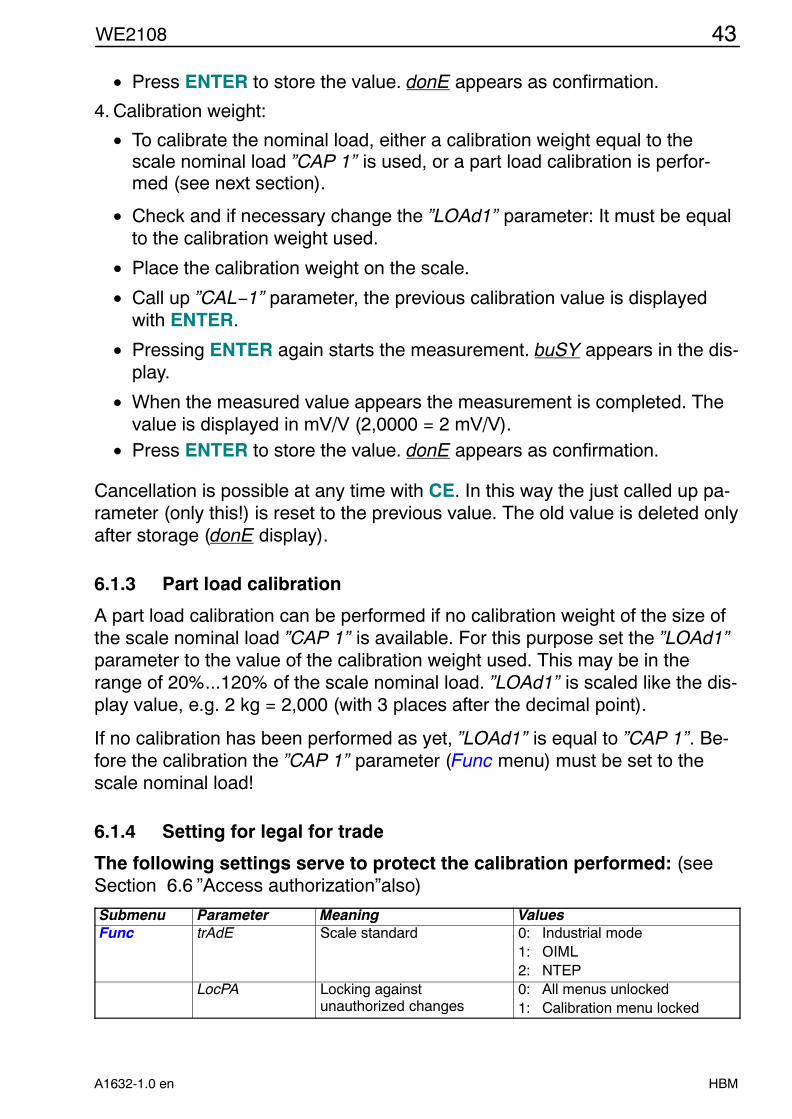
• Press ENTER to store the value. donE appears as confirmation.
4. Calibration weight:
• To calibrate the nominal load, either a calibration weight equal to thescale nominal load ”CAP 1” is used, or a part load calibration is perfor-med (see next section).
• Check and if necessary change the ”LOAd1” parameter: It must be equalto the calibration weight used.
• Place the calibration weight on the scale.
• Call up ”CAL−1” parameter, the previous calibration value is displayedwith ENTER.
• Pressing ENTER again starts the measurement. buSY appears in the dis-play.
• When the measured value appears the measurement is completed. Thevalue is displayed in mV/V (2,0000 = 2 mV/V).
• Press ENTER to store the value. donE appears as confirmation.
Cancellation is possible at any time with CE. In this way the just called up pa-rameter (only this!) is reset to the previous value. The old value is deleted onlyafter storage (donE display).
6.1.3 Part load calibration
A part load calibration can be performed if no calibration weight of the size ofthe scale nominal load ”CAP 1” is available. For this purpose set the ”LOAd1”parameter to the value of the calibration weight used. This may be in therange of 20%...120% of the scale nominal load. ”LOAd1” is scaled like the dis-play value, e.g. 2 kg = 2,000 (with 3 places after the decimal point).
If no calibration has been performed as yet, ”LOAd1” is equal to ”CAP 1”. Be-fore the calibration the ”CAP 1” parameter (Func menu) must be set to thescale nominal load!
6.1.4 Setting for legal for trade
The following settings serve to protect the calibration performed: (seeSection 6.6 ”Access authorization”also)
Submenu Parameter Meaning ValuesFunc trAdE Scale standard 0: Industrial mode
1: OIML2: NTEP
LocPA Locking againstunauthorized changes
0: All menus unlocked1: Calibration menu locked

44 WE2108
HBM A1632-1.0 en
6.2 Special applications
Further functions having influence on the weight indication of the WE2108 arelisted below. The settings can be relevant for legal for trade approval, there-fore changes are not possible with the access lock activated (exception: filtersetting). The parameters are set ex works to standard values. You thereforedo not need to make any changes if the corresponding function should not beused.
Further scale types:Submenu Parameter Meaning
Func tyPE
0: Counting scale1: One−range scale (set ex works)2: Two−range scale3: Two−interval scale
The following applies for two−range / two−interval scales:Submenu Parameter Meaning
rES−1 Range 1: Scale interval
FuncCAP 1 Range 1: Nominal load
Func rES−2 Range 2: Scale intervalCAP 2 Range 2: Nominal load
On calibration in the factory (before transporting to the installation site):Submenu Parameter MeaningFunc ALt, LAt Calculation of the acceleration due to gravity, see Section 6.5
For scale attachments with linearity errors:Submenu Parameter MeaningCAL Lin Characteristic linearization, see Section 6.3
Further functions:Submenu Parameter Meaning Instructions see SectionFiL F_FiL, Icr Filter 7.1Func F_tAr Preset tare function 5.1.6 + 5.3.2 In the mainmenu
P_tAr Preset tare value 5.1.6 + 5.3.2
AutoZ Switch−on zero 5.2.3
FuncZtrAC Zero tracking 5.2.3
Func StiLL Standstill monitoring 5.2.3 F_InP Tilt monitoring 7.3

45WE2108
HBMA1632-1.0 en
6.3 Calibration with linearization
The standard calibration with zero and final value is sufficient for the majorityof scale applications (”Lin” = 0). Only if inadmissible errors occur in this pro-cess, the signal should be linearized (”Lin” = 1/2). Linearization corrects errorsin scale attachments the output signal of which is not proportional to theweight (e.g. due to mechanical transmission elements).
6.3.1 Selection of the calibration method with the ”Lin” parameter
”Lin” parameter 0 1 2Calibration steps: Zero value,
final value !)Zero value,
2 calibration weightsZero value,
3 calibration weightsPart load calibrationpossible:
yes no no
Recommended for: Standard application Attachments withlinearity errors
Attachments withlinearity errors
Correction of followingerrors possible:
Error proportional tomeasured value
One maximum of theerror curve
Two maximum of theerror curve
Example:
(error of the scale out-put signal according toOIML)Description in section 6.1.2 6.3.2 6.3.2 !) The zero and final value calibration is already described in 6.1.2 ”Calibration (standard method)”.
6.3.2 Calibration steps for linearization (3 or 4 points)
First set the scale data:Submenu Parameter Meaning Values
Func
unit Displayed dimensional unit 0: none1: g2: kg3: t4: lb
Point Places after the decimalpoint of the display
e.g. 3 for ”6,000 kg”
rES−1 Scale intervalCAP 1 Nominal range of the scale e.g. 6000 for ”6,000 kg”
Required additional functions can be activated corresponding to section 5.2.3 ”Complete menu structure”.
Calibration is performed at several points, i.e. with unloaded scale as well asafter placing different calibration weights on the scale. The part weights usedmust be entered in ascending order. A part load calibration is not possible, i.e.the last weight must be equal to the scale nominal value. The characteristicinput with linearization replaces the zero and final value calibration, so thisdoes not need to be performed previously.

46 WE2108
HBM A1632-1.0 en
1. Call up the CAL menu.
2. Set the ”Lin” parameter (see following tables).
3. Zero value:
• Call up the parameter ”CAL−0”, the previous calibration value is dis-played with ENTER.
• Leave the scale unloaded.
• Pressing ENTER again starts the measurement. buSY appears in the dis-play.
• When the measured value is displayed, the measurement is completed.The value is displayed in mV/V (2,0000 = 2 mV/V).
• Press ENTER to store the value. donE appears as confirmation.
4. Weight for the first calibration value:
• Set the ”LOAd1” parameter to the value of the calibration weight.”LOAd1” is scaled like the indicated value, e.g. 2 kg = 2,000 (with 3 pla-ces after the decimal point).
• Place the calibration weight on the scale.
• Call up ”CAL−1” parameter, the previous calibration value is displayedwith ENTER.
• Pressing ENTER again starts the measurement. buSY appears in the dis-play.
• When the measured value is displayed, the measurement is completed.The value is displayed in mV/V (2,0000 = 2 mV/V).
• Press ENTER to store the value. donE appears as confirmation.
These operating steps must be performed for all weight values correspondingto the following table:
Calibration at 3 points
Parameter Action ValueLin Linearization Set to ”Lin” = 1CAL−0 Measure (scale unloaded) automatical measurementLOAd1 Enter value (calibration weight 1) ”LOAd1” < ”LOAd2”CAL−1 Measure with calibration weight 1 automatical measurementLOAd2 Enter value (calibration weight 2) ”LOAd2” = nominal loadCAL−2 Measure with calibration weight 2 automatical measurement

47WE2108
HBMA1632-1.0 en
For an optimum correction the calibration weight 1 should be in the range inwhich the greatest deviations of the characteristic occur:
LOAd1 LOAd2(Nominal load)
Calibration at 4 pointsParameter Action ValueLin Linearization Set to ”Lin” = 2CAL−0 Measure (scale unloaded) automatical measurementLOAd1 Enter value (calibration weight 1) ”LOAd1” < ”LOAd2”CAL−1 Measure with calibration weight 1 automatical measurementLOAd2 Enter value (calibration weight 2) ”LOAd2” < ”LOAd3”CAL−2 Measure with calibration weight 2 automatical measurementLOAd3 Enter value (calibration weight 3) ”LOAd3” = Nominal loadCAL−3 Measure with calibration weight 3 automatical measurement
LOAd1 LOAd2 LOAd3(Nominal load)
6.4 Direct entry of the characteristic values
The internal measured value processing of the WE2108 is adapted by the ca-libration to the values which actually arise at the zero and nominal value of thescale. These differ as a rule from zero and full deflection of the measuringelectronics, because
• the load cell is also loaded by the weight of the empty platform• the maximum load of the load cell is greater than the nominal range of the
scale(see also Section 6.1 ”Quick start without special functions”)The internal values were measured automatically in the calibration instruc-tions of the preceding chapter. Known values can also be entered directly in-stead of these.
48 WE2108
HBM A1632-1.0 en
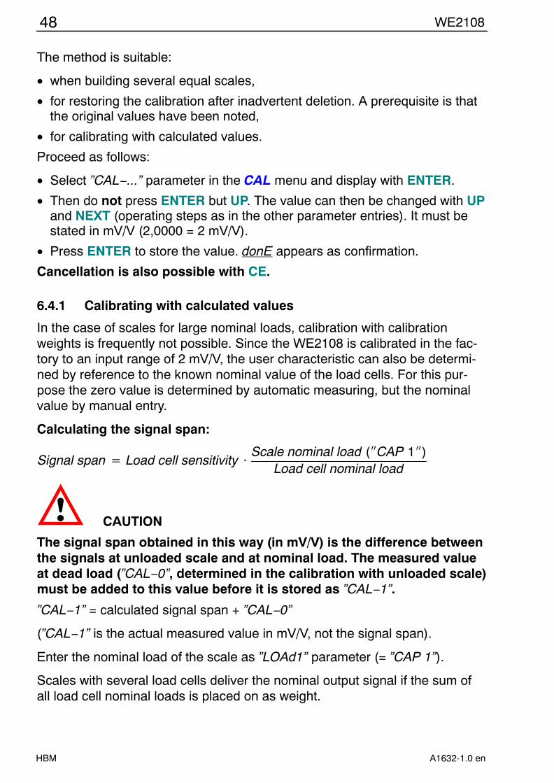
The method is suitable:
• when building several equal scales,
• for restoring the calibration after inadvertent deletion. A prerequisite is thatthe original values have been noted,
• for calibrating with calculated values.
Proceed as follows:
• Select ”CAL−...” parameter in the CAL menu and display with ENTER.
• Then do not press ENTER but UP. The value can then be changed with UPand NEXT (operating steps as in the other parameter entries). It must bestated in mV/V (2,0000 = 2 mV/V).
• Press ENTER to store the value. donE appears as confirmation.
Cancellation is also possible with CE.
6.4.1 Calibrating with calculated values
In the case of scales for large nominal loads, calibration with calibrationweights is frequently not possible. Since the WE2108 is calibrated in the fac-tory to an input range of 2 mV/V, the user characteristic can also be determi-ned by reference to the known nominal value of the load cells. For this pur-pose the zero value is determined by automatic measuring, but the nominalvalue by manual entry.
Calculating the signal span:
Signal span Load cell sensitivity Scale nominal load (ICAP 1I)Load cell nominal load
CAUTION
The signal span obtained in this way (in mV/V) is the difference betweenthe signals at unloaded scale and at nominal load. The measured valueat dead load (”CAL−0”, determined in the calibration with unloaded scale)must be added to this value before it is stored as ”CAL−1”.
”CAL−1” = calculated signal span + ”CAL−0”
(”CAL−1” is the actual measured value in mV/V, not the signal span).
Enter the nominal load of the scale as ”LOAd1” parameter (= ”CAP 1”).
Scales with several load cells deliver the nominal output signal if the sum ofall load cell nominal loads is placed on as weight.

49WE2108
HBMA1632-1.0 en
Example:
Parallel connection of 4 load cells of 20 t, sensitivity 2 mV/V.Nominal load of the scale 60 t, 6000 divisions, resolution step 0,01 t.
1. Setting the scale parameters in the Func menu:
• Display unit (tonnes): ”unit” = 3
• Places after the decimal point: ”Point” = 2
• One−range scale: ”tYPE” = 1
• Resolution step: ”RES1” = 1
• Scale nominal load 60 t: ”CAP 1” = 60.00
2. Calibration of the user characteristic in the CAL menu:
• Perform zero point calibration.
• A nominal value of 4 x 20 t = 80 t (at 2mV/V) results from the parallel connection.
Signal span 2 mVV 60 t4 20 t
1.5 mVV
• Read off dead load signal in the menu (”CAL−0” parameter)Example: ”CAL−0” = 0.3000 = 0.3 m V/VThen exit the menu item with CE, since otherwise there is a new measurement!
• Signal at nominal load = Signal span + dead load signal= [1.5 mV/V] + [0.3 mV/V]= 1.8 mV/V
• Therefore enter 1.8000 under ”CAL−1”
6.5 Influence of the geographical installation site
The function described below enables calibration at the scale manufacturer,even if the unit should be operated in another geographical position (heightabove sea level, latitude).
This setting is not required for calibration on site!
The acceleration due to gravity and thus the display of the scale dependsupon the geographical data (latitude and height above sea level) of the instal-lation site. The change between different regions is a maximum of 0.1 % wit-hin Germany, 0.6 % worldwide.
If this error influence at the new installation site exceeds the accuracy limits ofthe scale, a recalibration is required as a rule. Instead of this, the influence ofthe installation site can be compensated for by an internal correction functionof the WE2108.

50 WE2108
HBM A1632-1.0 en
For this purpose enter in the Func menu (access authorization required !):
• ”LAt” = the latitude
• ”ALt” = the height above sea level in multiples of 100 m (e.g. 12 = 1200 mabove sea level).
A prerequisite for the correction calculation is that the values of the calibrationlocation are entered before the calibration with calibration weights.
The values for Darmstadt are set ex works: ”LAt” = 50, ”ALt” = 1.
When calibrating at another place, these values must be adapted correspon-dingly (firstly set ”LAt” and ”ALt”, then calibrate).
On a change of location, then only the new values have to be entered. If ”LAt”and ”ALt” do not correspond to the actual location when calibrating, errorsarise at the new location, even if the scale displays correctly in the calibration.The correction calculation cannot be used then, instead of this the scale mustbe calibrated with weights at the new location. The correct settings before andafter the calibration are in the responsibility of the scale operator or installer.
The correction calculation can be deactivated with the setting ”LAt” = 91. Thedisplay is then always related to the location of the last calibration.
6.6 Access authorization
Data relevant to calibration (e.g. the nominal load and load unit of the scale)as well as the calibration should be protected against unauthorized changing.For this purpose the corresponding menu items can be locked by setting the”LocPA” parameters in the Func menu to 1. When the menu is called upagain, the corresponding subitems no longer appear or cannot be changed. Inorder to obtain access nevertheless, the concealed calibration button must bepressed before the parameter menu is called up. The button is accessiblethrough the opening on the left below on the front of the unit (see 3.1.1 ) andcan be activated with a pointed object. In operation the opening must be clo-sed with the enclosed adhesive mark or in the case of legal for trade applica-tions with the calibration mark. ”LocPA” can also no longer be reset withoutactivating the button.
If the scale is protected in this way, access to the data relevant to legal fortrade applications is possible:
• after activating the concealed button
or • with a computer (serial interface) after entering the password

51WE2108
HBMA1632-1.0 en
Independently of this, every change relevant to legal for trade applicationscauses the calibration counter to be incremented in the case of legal for tradeapplications (i.e. in the OIML or NTEP mode, ”trAdE” parameter). In the indu-strial mode (”trAdE” = 0) the calibration counter remains unchanged. This isindependent of the locking of the menu items by the ”LocPA” parameter.
NOTEThe WE2108 offers the possibility of locking all parameter changes by acontrol input (e.g. with an external key switch). In this case activatingthe concealed button also has no effect.
F_InP parameter !) Switch statusInput 2
”LocPA” parameter
Concealed buttonpressed
Access to calibrationparameters
2 or 3 active −− −− noopen −− −− yes
others (not 2 or 3)
−− 1 no no
−− 1 yes (before menucall−up)
yes
−− 0 −− yes!) For setting up the lock, the parameter ”F_InP” is to be set to the function ”parameter lock” as described in
Section 7.3 ”Inputs”. This has the effect that the parameters are released by the external switch, irrespec-tive of the concealed button. Therefore, setup with ”F_InP” should be effected only, if the input is reallyused for parameter protection.
6.6.1 Pushbutton lock
With an appropriate setting of ”F_InP” (see Section 7.3), all pushbuttons of theunit can be blocked by a control input (e.g. with an external key switch). Thislocks scale functions (e.g. taring) and the menu.
6.7 Selection of suitable load cells
6.7.1 Division number:
When configuring the scale in the parameter menu you set the nominal weightof the scale (display value at nominal load) and the numeral step. The divisionnumber results as quotient of these values and therefore cannot be set sepa-rately. Take care that it is not larger than the division number of the legal fortrade approval.
6.7.2 Supply voltage and measuring signal:
The WE2108 works with 6.5 V direct voltage supply, a lower voltage can bepresent at the load cell due to losses in the cable and possibly existing Zenerbarrier. The output signal span of the load cell(s) must be in the range from0.2 to 2.7 mV/V.

52 WE2108
HBM A1632-1.0 en
6.7.3 Dead load and nominal value:
Adaptation to the dead load and possible part utilization (user characteristic)of the load cell takes place in the calibration of the scale in the parametermenu. The WE2108 processes the measured values internally with a higheraccuracy than the display requires. In the case of legal for trade applications,however, the minimum sensitivity of 1 mV / scale interval must be observed.Characteristics in which this value is not reached can result due to extremevalues of dead load and part utilization. This must be taken into account in thedesign of the scale. The following formula applies for checking:
Sensitivity mVe 1000 Supply voltage [V] Nom. Sensitivity of the LC mVV Nom. load of the Scale
Nom. load of the LC Number of calibration steps
Example: Supply voltage 6.5 V; Load cell 100 kg = 2 mV/V; Scale with 60 kg and 6000 d
Sensitivity 1000 6.5 V 2 mVV 60 kg
100 kg 6000 1.3 mVe
In the case of an application which is not legal for trade, the resolution and theload cell utilization can be freely selected. However, observe that with lowersensitivity greater unquiet and drift of the measured value must be expected.
In the calibration commands in the parameter menu, the WE2108 displays theoutput signals of the load cells in mV/V, so that a statement about the utiliza-tion of the load cell is possible.

53WE2108
HBMA1632-1.0 en
7 Further functions
7.1 Filtering
The WE 2108 has flexible analog and digital filter functions, in order to obtaina stable measured value with a short transient time. The setting ex works issufficient as a rule for scales with up to 6000 divisions at 1 µV/e. Changes arepossible in the FiL menu:
• ”F_FiL” sets the cut−off frequency of the filter, see menu table.
• ”Icr” is an additional averaging over 1 ... 99 values. Use this function to ob-tain a quiet measured value with very slow fluctuations of the measured va-lue (e.g. silo weighing under wind load). The measuring rate is not influen-ced by this (moving average filter).
Also with the slowest filter setting it is guaranteed that the display does not re-main on the old value longer than one second after a load change (but see7.1.2 ”Special filter for animal scales”).
7.1.1 Filter and standstill
Large values of ”Icr” increase the transient time. The standstill display (if acti-vated) is adapted automatically. The dimensional unit or the C−character forcounting scale operation is displayed only if a stable value stands in the dis-play as long as it corresponds to the transient time. With an abrupt change,the dimensional unit therefore appears only after double the transient time.
7.1.2 Special filter for animal scales
This filter provides for a quiescent indication even in the case of animals mo-ving on the scale platform. Shunt forces, e.g. by an animal supporting it-self on a fixedly mounted gate, must be avoided however.
Required settings
The filter is activated by means of the setting ”F_FiL” = 8 (or the interfacecommand ASF8). By varying the parameter ”Icr” the time behaviour of the fil-ter can be adapted to the application:
Large values for ”Icr” provide for the filtration of major weight variations, butalso extend the duration up to the standstill display. The smallest meaningfulvalue for ”Icr” is 16. Smaller values are permitted but they lead to the same fil-ter behaviour as the setting 16.
For the animal filter, a standstill criterion must always be active. The stepwidth can be freely selected(Parameter ”StiLL” = 1...9) from 1d to 9 d, the pre-set time interval (1 / 0.5 / 0.2 seconds) does not have any influence. The set-tings 0, 10 and 20 are treated as a setting 1 (test for 1d).

54 WE2108
HBM A1632-1.0 en
Indication behaviour
The measuring time can be a few seconds. As soon as a valid measured va-lue was formed, this is displayed together with the measurement unit. Even ifthe animals continue to move the value continues to be displayed. The filterdetermines the weight which the platform would be subjected to in the case ofnon−moving animals. If no plausible value can be formed from the measuringsignal, the symbol Hold is initially shown as an indication, after a few secondsthe measured value is discarded.
This may be for the following reasons:
• the total weight has changed
• the animal is held by a person not standing on the platform
• the animal is tethered outside the platform
• other shunt forces
NOTEThe settings with regard to number of parts, standstill step width etc.are to be made by the owner with due consideration for the relevantscale approval.
7.2 Limit outputs
The WE2108 has two programmable switching outputs. Each channel beco-mes active on exceeding the switch−on value and inactive when dropping be-low the switch−off value. A freely selectable hysteresis results from differentvalues. The values can be related optionally to the gross or net weight, this isindependent of the current display mode. Active limit channels are indicated inthe display by the 1 or 2 symbols (only for one−range scales, since the sym-bols are otherwise used for the range display).
The control outputs of the unit are open−collector outputs which switch to theunit ground. The assignment of the levels to the limit status can be selected viathe ”P1_Lo” or ”P2_Lo” parameter and is explained in the following table. Loads(relays, lamps) must be switched to a positive supply voltage (max. 40 V).
Logical levels can also be output by using a pull−up resistor. Connect a freewheeling diode parallel to inductive loads (e.g. relays).

55WE2108
HBMA1632-1.0 en
ParameterPx_Lo
Weight Limit status o. C. – switch Output level
0 under switch−off value inactive closed Low0 over switch−on value activ open High1 under switch−off value inactive open High1 over switch−on value activ closed Low
between switch−onand switch−off value
Status remainsunchanged
The relevant output switches off on overcurrent. To reset the fuse switch offthe output for around 30 seconds (according to logic by exceeding or droppingbelow the limit). Alternatively the WE2108 can also be switched off.
7.3 Inputs
The switching inputs of the WE2108 can be assigned the following functions:• Operating the scale with external buttons (e.g. on a vehicle scale)
• Control by a PLC
• Monitoring the scale structure by an inclination switch
• Blocking all calibration parameters against change (menu and interface)
• Locking the control keys
The inputs are inactive ex works, the functions are assigned in two steps:
1. Activating the parameter locking device or inclination monitoring with the”F_InP” parameter. This setting (in the Func menu) is relevant to legal fortrade applications. It can be protected like the calibration (access only afteractivating the concealed button), changes are registered with the calibra-tion counter.
2. The inputs which are not assigned one of the listed functions can be assi-gned to a scale function in the ioSEt menu (”Fin 1”, ”Fin 2” parameter).This is also permissible at any time with legal for trade applications.
The following combinations can be set with the ”F_InP” parameter:F_InP Input 1 Input 2
0 free for Scale functions free for Scale functions1 Inclination switch free for Scale functions2 free for Scale functions Parameter locking device3 Inclination switch Parameter locking device4 free for Scale functions Inclination switch5 Inclination switch Pushbutton lock6 free for Scale functions Inclination switch

56 WE2108
HBM A1632-1.0 en
Scale function for Input 1 (”Fin 1” parameter)F_InP Fin 1 Function
0; 2; 4; 6 0 None1 Taring2 Print3 Gross / Net4 Alternatingly for each activation:
− Taring− Switching over to gross
1; 3; 5 −− no Scale function (input occupied with inclination switch)
Scale function for Input 2 (”Fin 2” parameter)F_InP Fin 2 Function0; 1 0 None
1 Taring2 Print3 Gross / Net
2; 3 −− no Scale function (input for parameter locking device)4 −− no Scale function (input occupied with inclination switch)
5; 6 −− no Scale function (input for pushbutton lock)
Electrical properties and level assignment:
Connect a switch / button between the Pin1 and GND terminals (input 1) orPin2 and GND (input 2) to activate an input. An additional power supply is notrequired. Alternatively control voltages which are related to unit ground (GND)can also be applied to Pin 1 / Pin 2. In this case the level limits stated belowmust be observed.
”inactive” ”active”Status when connecting aswitch
Input open (quiescent level approx. 5 V)
Input connected with ground
Status when controlled bymeans of an external voltage
min. 3.5 Vmax. 35 V
min. −30 Vmax. 0.4 V
TAR, Print, G/N no action Function is performedParameter locking device Change possible Change lockedinclination switch Measuring mode tilt displayedpushbutton lock Release control keys Control keys locked
The scale functions (TAR, Print, G/N) are performed once on closing the con-tact. If both contacts are closed after one another permanently, only the func-tion of the first activated input is performed. Undefined levels and oscillationsat the inputs must be avoided.

57WE2108
HBMA1632-1.0 en
7.4 Printing function
A printer can be connected to the serial interface of the WE2108 for outputtingthe weight values. The communication uses the XON / XOFF protocol. The in-terface must previously be set to the ”Printing” mode (”F_SEr” = 1 in the ioSEtmenu). The Print menu is then accessible.
The printing process is released manually by pressing the key (Print).
Further information can be printed in addition to the weight value. You selectthe type of the information to be output corresponding to the following tablewith the ”F_Prt” parameter (printer function):
F_Prt Print output (one line for each component)0 Printing function deactivated1 Measured value2 Date; Measured value3 Date; Time; Measured value4 Text line; Measured value5 Running number; Measured value6 Date; Running number; Measured value7 Text line; Date; Running number; Measured value8 Text line; Date; Time; Running number; Measured value9 Date; Time; Running number; Measured value
Tab. 6.1
The ”Text line” is user−defined. The input is possible only through a PC, forthis purpose the interface must be set to the ”Computer coupling” function (ioSEt / ”F_Ser” = 2). Afterwards change this setting back to ”Printing”.
The running number (counting range 0 ... 99999) is increased with each prin-tout and is maintained even after the unit is switched off (from P83). A reset ispossible in the menu Add / ”Clr_P”.
The printing output depends upon the operating state of the scale andalways corresponds to the display. For example for printing function 2there results:
Gross:Date: 05.12.98
G 34,65 kg
Net:Date: 05.12.98
N 34,65 kg
T 9,80 kg

58 WE2108
HBM A1632-1.0 en
Net (Preset tare):Date: 05.12.98
N 34,65 kg
T 10,00 kg PT
Counting scale (Gross):Date: 05.12.98
CG 43 Pcs
The printout occurs only at standstill, therefore the dimensional unit is alwaysprinted. It is possible to print as frequently as desired in an application whichis not legal for trade.
In the case of a legal for trade setting, the printout cannot be repeated. Thereis a new printout only at weight change and renewed standstill. There is noprinting outside the displayed limits.
If an article number was entered in the Print menu, it appears in an additionalline above the measured value. Set the article number to 0 to switch off.
7.5 Formatting of the printing output
The above listed components are printed out in each case one line below theother. To print a certain area of a form, the entire block can be shifted by thefollowing parameters:
• ”SPACE”: Number of spaces before each component (= indenting to the right)
• ”LnEF1”: Number of blank lines before starting the text block
• ”LnEF2”: Number of blank lines after the printout. This parameter servesfor feeding ”LnEF2” : Number of blank lines after the printout. Thisparameter serves for feeding entire pages instead of a form feedfunction. The lines are counted starting at the first line of the print-out. With consecutive printouts the distance between the textblocks is equal to the sum of ”LnEF1” and ”LnEF2”, independentlyof how many lines the printout itself consists of. ”LnEF2” thereforedoes not have to be adapted when changing the print protocol.This applies under the prerequisite that ”LnEF2” corresponds atleast to the number of printed lines.
The factory setting is ”F_Prt” = 1
”SPACE” = 0
”LnEF1” = 0
”LnEF2” = 2

59WE2108
HBMA1632-1.0 en
7.5.1 Example
”F_Prt” = 2 (Date; Measured value)
”Art_No” = 1234
”SPACE” = 4
”LnEF1” = 2
”LnEF2” = 6
−−−−−−−−−−−−−−−−−−−
>
>
>>>>Date: 05.12.98
>>>>Art−No: 1234
>>>>G 34,65 kg
>
>
>
−−−−−−−−−−−−−−−−−−−
(The characters ”>” and ”−” are not printed.)
Printer-specific control codes can be automatically inserted prior to or afterprinting (e. g. cutting the paper or inserting an internal printer time).Programming is carried out one time using the PCA and PCB commands, seepart 2 of the manual on the computer commands.
7.6 Setting the time
The internal clock of the WE2108 serves for outputting date and time whenprinting and is of no importance for the other unit functions. The setting ismade in the Print menu. The clock runs on with the unit switched off as longas the operating voltage is applied. After a power interruption the last validdate is retained, the clock starts to run at 00:00:00.
7.7 Summing function
7.7.1 Overview
For summing the key ”Print” ( ) is also used. Operation of this key trig-gers the following:
• Add the current display value to the total sum memory, if the summing func-tion has been activated.
• Printing the measured value, if the interface is set to ”Printing” and a printprotocol has been activated. If, in addition, the summing function is active,then the sum and the number of the summed values is printed out.

60 WE2108
HBM A1632-1.0 en
After summing has been effected, the text AddEd appears in the display for 1second.
If there is no standstill condition when the key is operated, the request is sto-red and executed after the standstill has been reached (summing and, if nec.,printing).
In the case of legal for trade applications, summing behaves like printing, thatis, a second addition is only possible after a change and a renewed standstillof the value.
Summing is not executed if the maximum values for sum or count are excee-ded, as well as in weight mode with an activated counting scale (see below).
Sum and count are stored in non−volatile memory and will be available evenafter the supply has been interrupted.
The following commands are available for controlling the print function via theinterface:
• add
• sum
• csn
See Reference Manual Part 2 (Description of the commands for computer in-tegration).
7.7.2 Functions in the menu Add (new)
”F_Add” Switching the summing function on / off
”totAL” Display of the sum 1)
”t_nbr” Display of the summand counter
”cLr_t” Deletion of sum and summand counter
”Prtno” Display of running number for print output
”cLr_P” Deletion of running number
1) Sum values with more than 5 digits are indicated in two steps:
• Indication of the higher value digits (marked by the symbol 1 in the top leftcorner of the display) without measurement unit
• Indication of the lower value digits (marked by the symbol 2 in the top leftcorner of the display) with measurement unit
7.7.3 Permitted range
The value added is always the display value, switchover gross/net is possiblebetween several summands! The sum of all values as well as the number ofsummands is stored.

61WE2108
HBMA1632-1.0 en
It is not possible to subtract the most recent value!
A maximum of 21000 values are added. This ensures that even for the maxi-mum value of each summand (99999) no overflow of the sum is possible.
Individual values as well as sums may be negative, but only for values with upto 9 digits (due to printout requirements: 15 characters *−123456,789 kg).
When the limits are exceeded, adding stops. Instead of the sum, the followingnote is printed:
Sum OverflowNot added
Instead of AddEd the error message Err15 appears in the display.
7.7.4 Deletion of the sums
For deletion there are two options:
• in the menu Add, menu item ”cLr_t”, deletion must be confirmed again bypressing ENTER. With an active print function, the sum is printed again be-fore deletion (without the current measured value).
• via the interface (command csn)
Also, the sum is always deleted if by any changes in the scale parameters thevalues to be added no longer fit the existing sum.
This occurs in the following cases (without any repeat printout of the sum):
• Changes in the menu CAL
• The commands CAP, LWT, LVA, (SFA, TMI, TMP)
• The command LGC and subsequent storage with TDD1
• The ”dEfLt”−function in the menu FACt
7.7.5 Summing function during counting scale operation
If the function ”counting scale” in the WE2108 has been generally approved(parameter ”tYPE” = 0, menu Func), the summing function only acts on thecounting results. Weight values cannot be added. However, even in this modeof operation, the scale can indicate weight values, only by referencing (doublekey operation) will the display change over to the number of pieces / items.
For the summing function, the following applies:
If ”tYPE” is set to 0, only quantities (number of pieces) are added which arealso indicated in the display. If a summing is requested during a weight indica-tion, the following occurs:
• Sum and counter remain unchanged
• The display does not show the note added

62 WE2108
HBM A1632-1.0 en
• If the print function is active, the current weight value is printed, plus thenoteNo count value
not added
For adding weight values, the counting scale function must be generally deac-tivated. (”tYPE” > 0)
7.7.6 Print
Printed Data:
• Current value with G/N symbol, further data according to the preset protocol(”F_Prt”, see Section 7.4 ”Printing function”)
• In addition: summand counter and sum value without G/N (!)
Example (Printing function 2):Date: 05.12.98
N = 34,65 kg
T = 9,80 kg
Total:
4 weighings
* 416,85 kg
The sum is marked by an asterisk and can be composed of gross and net va-lues (even mixed).

63WE2108
HBMA1632-1.0 en
7.8 Interface for large display (second display)
Output (1−2 values / second) is effected by the interface, if ”F_SEr” = 3 is set(in the menu ioSEt).
Output format for second display:
Byte no. Character output Remarks0 Start character (ST_CH)
or space characterIf set (ioSEt−menu)(otherwise)
1 G or N Gross / Net2 1, 2
or space characterFor dual range scale(otherwise)
3 o
−
Space character
”exact zero”
signs
(otherwise)4 Measured value numeral5 Measured value numeral or comma6 Measured value numeral or comma7 Measured value numeral or comma8 Measured value numeral or comma9 Measured value numeral
10 Space character11 Space character12 Measurement unit
Space character
at standstill
(otherwise)13 Measurement unit
Space character
at standstill
(otherwise)14 End character 1 as preset (ioSEt−menu)15 End character 2 as preset (ioSEt−menu)
Examples:
( ′ is not issued)
Output for valid measured values:
′ ′G′ ′o′ ′ ′0′,′0′0′ ′ ′k′g′<cr>′<lf>′
′ ′N′ ′ ′1′2′3′,′4′5′ ′ ′k′g′<cr>′<lf>′
Output for overflow:
′ ′ ′ ′ ′ ′ ′>′M′A′X′ ′ ′ ′ ′<cr>′<lf>′
Output for negative overflow:
′ ′ ′ ′ ′ ′ ′_′_′_′_′ ′ ′ ′ ′<cr>′<lf>′
Output during menu operation:
′ ′ ′ ′ ′P′a′r′a′m′.′ ′ ′ ′ ′<cr>′<lf>′
Output in the case of errors (ErrXX in the WE2108 display):
′ ′G′ ′ ′E′r′r′o′r′ ′ ′ ′ ′ ′<cr>′<lf>′

64 WE2108
HBM A1632-1.0 en
8 Troubleshooting
Error message Meaning Remedy
(marks above)
Measured value above the max.display range (depending upon theset scale standard)
Reduce load of the scale
Test set nominal load: ”CAP 1”, ”CAP 2”parameters in the Func menu
(marks below)
Measured value below the min.display range (depending upon theset scale standard)
For net display: switching over to gross
possible recalibration
Zeroing unsuccessful Remove disturbing influences on the scale(vibrations, wind).
Set higher filter.
Observe zero setting range (2% of the no-minal weight).
Taring unsuccessful Taring is possible only with a gross weightwithin the display range
For counting scale: weight of thereference quantity too low
Larger reference quantity, at least 1/10 000 of the nominal range
1. Summing not possible
2. Sum overflow
1. Activate counting mode or changescale type (see Section 7.7.5 )
2. Delete sumsThe entered value is larger thanthe setting range of the parameter
Repeat entry, observe setting range(see Section 5.2.3 ”Complete menustructure”)
Error on new entry of the factorycalibration (only with PC−connection)
Enter/measure values in the ordersza, szu, sfa
Internal software error Report to manufacturer
Analog−digital converter not working
Check contact and polarity of the load cellconnections. All terminals must be con-nected, in four−wire connection observeSection 3.2.3 ”Load cell connection”.
Load cell supply not constant Test supply voltage for losses
Error on writing into the non−vola-tile memory
Test supply voltage for losses
Factory characteristic faulty Repair or re−enter values
Temperature compensation faulty Repair
Unusable values in calibration orlinearization
− Repeat calibration
− Place weights on scale on linearizationin ascending order
Part load calibration outside theallowed range
20 ... 120 % of the scale nominal load
Overload of the scale (>130 % ofthe nominal load)
Overload can damage the load cells, pos-sibly test display with calibration weights
Internal setting of the interfacefaulty
Report to manufacturer
Overrun of the interface Test baud rate setting on WE2108 andconnected unit
Framing error of the interface Test baud rate setting on WE2108 andconnected unit

65WE2108
HBMA1632-1.0 en
Parity error of the interface Test parity setting (even/odd/none)
Error on output of the transmit buffer
Report to manufacturer
Overflow of the reception buffer onPC interfacing
Send commands from external software atlarger interval
Overflow of the watchdog timer Report to manufacturer
Inadmissible interrupt Report to manufacturer
Loss of unit parameters in the non-volatile memory
Report to manufacturer
Overflow of the calibration counter Repair
= ”no Access”
3. It was attempted to change alegal for trade relevant parame-ter without access authoriza-tion.
4. Parameters are locked by anexternal key switch.
1. Before calling up the parameter menuactivate the concealed calibration but-ton.
2. Release of the external lockingdevice (see Section 6.6 ”Accessauthorization”)
Error Possible cause RemedyThe unit swit-ches itself on orconsumes toomuchstand−by cur-rent
Undefined level at the process in-puts
(only if connected)
Level clearly high (>4 V)
or low (<0,8 V)
Supply voltage too low U(min) = rms value less residual ripple >10 V
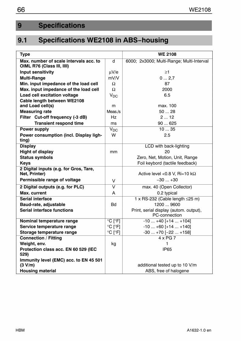
66 WE2108
HBM A1632-1.0 en
9 Specifications
9.1 Specifications WE2108 in ABS−housing
Type WE 2108
Max. number of scale intervals acc. toOIML R76 (Class III, IIII)Input sensitivity
d
µV/e
6000; 2x3000; Multi-Range; Multi-Interval
≥1Multi-Range mV/V 0 ... 2,7Min. input impedance of the load cell Ω 87Max. input impedance of the load cell Ω 2000Load cell excitation voltage VDC 6.5Cable length between WE2108 and Load cell(s) m max. 100Measuring rate Meas./s 50 ... 28Filter Cut-off frequency (-3 dB)
Transient respond timeHzms
2 ... 1290 ... 625
Power supplyPower consumption (incl. Display ligh-ting)
VDC
W10 ... 35
2.5
Display LCD with back-lightingHight of display mm 20Status symbols Zero, Net, Motion, Unit, RangeKeys Foil keybord (tactile feedback)2 Digital inputs (e.g. for Gros, Tare,Net, Printer)Permissible range of voltage V
Active level <0.8 V, Ri=10 kΩ−30 ... +30
2 Digital outputs (e.g. for PLC)Max. current
VA
max. 40 (Open Collector)0.2 typical
Serial interface 1 x RS-232 (Cable length ≤25 m)Baud-rate, adjustable Bd 1200 ... 9600Serial interface functions Print, serial display (autom. output),
PC-connectionNominal temperature range °C [°F] -10 ... +40 [+14 ... +104]Service temperature range °C [°F] -10 ... +60 [+14 ... +140]Storage temperature range °C [°F] -30 ... +70 [−22 ... +158]Connection / Fitting 4 x PG 7Weight, env. kg 1Protection class acc. EN 60 529 (IEC529)
IP65
Immunity level (EMC) acc. to EN 45 501(3 V/m) additional tested up to 10 V/mHousing material ABS, free of halogene

67WE2108
HBMA1632-1.0 en
9.2 Dimensions WE2108 in ABS−housing
View X
124
109
WE 2108
205
124
7244
117 X
12°
134
70
ENTER UP
CE NEXTMENU
G/N T
012°
X
Dimensions (in mm)

68 WE2108
HBM A1632-1.0 en
9.3 Specifications WE2108S/WE2108M in steel−housing
Types (with RS-232-Interface): WE2108S; WE2108MTypes (with RS 232 Interface):(with RS-485-Interface):
WE2108S; WE2108MWE2108S−485; WE2108M−485
Max. of scale intervals acc. to OIML R76(Class III, IIII)Input sensitivity
dµV/e
6000; 2 x 3000; Multi-Range; Multi-Interval
≥1Measuring range mV/V 0 ... 2.7Min. input impedance of the load cell Ω 87Max. input impedance of the load cell Ω 2000Load cell excitation voltage VDC 6.5Cable length between WE2108 and Load cell(s) m max. 100Measuring rate Meas./s 50 ... 28Filter Cut-off frequency (-3 dB)
Transient respond timeHzms
2 ... 1290 ... 625
Power supplyPower consumption (incl. display ligh-ting)
VDC
W10 ... 35
2.5
Display LCD with back-lightingHight of display mm 20Status symbols Zero, Net, Motion, Unit, RangeKeys Foil keyboard (tactile feedback)2 Digital-Inputs (e.g. Gros, Tare, Net, Printer)Permissible range of voltage V
Aktive level <0.8 V, Ri=10 kΩ−30 ... +30
2 Digital-Outputs (e.g. for PLC)max. current
VA
max. 40 (Open Collector)0.2 typ.
Serial interface 1 x RS-232 or 1 x RS-485Baud-rate, adjustable Bd 1200 ... 9600Serial interface functions Print, serial display (autom. output),
PC−connection via RS-232 or RS-485Nominal temperature range °C [°F] -10 ... +40 [+14 ... +104]Service temperature range °C [°F] -10 ... +60 [+14 ... +140]Storage temperature range °C [°F] -30 ... +70 [−22 ... +158]Connection / Fitting
WE2108S(−485):WE2108M(−485):
5 x Pg 7Screw terminal
Weight, env. WE2108S(−485):WE2108M(−485): kg 1.8
1Protection class acc. to EN 60 529 (IEC 529) IP65 (WE2108M only frontplate)
Immunity level (EMC) acc. to EN 45 501(3 V/m) additonal testet up to 10 V/mHousing material Stainless steel (WE2108M only frontplate)

69WE2108
HBMA1632-1.0 en
9.4 Dimensions WE2108S/WE2108M in steel−housing
Dimensions (in mm)
ENTER UP
NEXTMENU
0
T
CE
G/N
Cable fitting5 x Pg7
240
140
228∅
4.5
WE2108S (Wall mounting or Desktop unit)
24096
140
115
108
180
ENTER UP
NEXTMENU
0
T
CE
G/N
WE2108M (Panel mounting)
96
274
150
210
80
∅ 8
∅ 4
2322
.528
Detail X
Detail X

70 WE2108
HBM A1632-1.0 en


Hottinger Baldwin Messtechnik GmbH
Postfach 10 01 51, D-64201 DarmstadtIm Tiefen See 45, D-64293 DarmstadtTel.: 06151 803-0 Fax: 06151 8039100E−mail: [email protected] Internt: www.hbm.com
Änderungen vorbehalten.Alle Angaben beschreiben unsere Produkte in allgemeiner Form.Sie stellen keine Eigenschaftszusicherung im Sinne des §459,Abs. 2, BGB dar und begründen keine Haftung.
A1632-1.0 en