we are pleased that you have chosen a - …pdf.textfiles.com/manuals/firearms/browning_a500.pdf ·...
TRANSCRIPT


We are pleased that you have chosen aBrowning A-500 shotgun.It is certainly a gun you can be proud to own. Itrepresents the state-of-the-art in modern gun designand manufacturing. The processes of design, testingand manufacturing were all assisted by advancedcomputer systems. The result is superior dependability,greater ease-of-operation, smoother handling andmore reliable overall function. With a reasonableamount of care, your A-500 shotgun should give youmany years of dependable, enjoyable service. Pleasefeel free to write us immediately if you have anyobservations regarding its performance and operation.
Also, please take a moment to complete and mail inthe brief attached marketing survey card found on ourback cover. It helps us considerably in our constanteffort to provide you with better service.
NOTE: All current production A-500 shotguns have animproved trigger group assembly. You can confirm thisby the letter “H” stamped on the trigger guard. (SeeFigure 10 on page 37 of this manual.)
If your trigger guard does not have the letter "H”stamped on it then please contact our BrowningService Department toll free at 1-800-322-4626 forinformation on how to get the improved triggerassembly installed on your A-500.
Thank You.
Route #1 Morgan, Utah 84050
Distributed in Canada by Browning Canada Sports Ltd./Ltee, St-Laurent, Quebec H4S lS0
1

You Are Responsible for FirearmsSafety
As a gun owner, you accept a set of demandingresponsibilities. How seriously you take theseresponsibilities can be the difference between lifeand death. Mistakes made with guns are finaland cannot be paid for with money or regret.
There is no excuse for careless or abusivehandling of any firearm. At all times handle yourshotgun and any other firearm with intenserespect for its power and potential danger.
PLEASE READ AND UNDERSTAND ALL OFTHE CAUTIONS, PROPER HANDLINGPROCEDURES AND INSTRUCTIONSOUTLINED IN THIS BOOKLET BEFOREUSING YOUR NEW FIREARM.
ALWAYS KEEP THE MUZZLE OF YOURSHOTGUN POINTED IN A SAFEDIRECTION even though you are certainthe shotgun is unloaded. Never point anyfirearm at anything you do not intend toshoot. Be extremely alert and aware of allpersons and property within the range ofyour ammunition.
NEVER TRUST YOUR SHOTGUN’SMECHANICAL “SAFETY” DEVICE. The

word “safety” describes a gun’s triggerblock mechanism, sear block mechanism,hammer block mechanism or firing pinblock mechanism. These mechanicaldevices are designed to place your gun ina SAFER status. No guarantee can be madethat the gun will not fire even if the“safety” is in the “on safe” position. TheA-500 has a cross bolt “safety” whichblocks the gun’s trigger. See “Operation ofthe Safety” on page 15 for instructions onoperation of this gun’s safety.
Like any mechanical device, a “safety” cansometimes fail; it can be jarred orinadvertently manipulated into an unsafecondition. Mechanical “safeties” merely aidsafe gun handling and are no excuse forpointing your shotgun’s muzzle in anunsafe direction.
While it is a good idea to “test” yourshotgun’s mechanical “safeties” periodicallyfor proper function, NEVER TEST THE“SAFETY” WHILE YOUR SHOTGUN ISLOADED OR POINTED IN AN UNSAFEDIRECTION.
Safe gun handling does not stop with yourgun’s mechanical “safety” devices - itstarts there. Always treat this shotgun withthe respect due a loaded, ready-to-firefirearm.
WHENEVER YOU HANDLE A FIREARM,OR HAND IT TO SOMEONE, ALWAYSOPEN THE ACTION IMMEDIATELYVISUALLY CHECK YOUR SHOTGUN’SCHAMBER, FEED MECHANISM ANDMAGAZINE to be certain that they do notInadvertently contain any ammunition.Always keep the chamber empty and the“safety” in the “on safe” position unlessshooting is imminent.
DO NOT TRANSPORT YOUR SHOTGUNLOADED, WHETHER IN A SCABBARDGUN CASE, OR OTHER CONTAINER.
BE WARE OF BARREL OBSTRUCTIONS,for the safety of both your gun andyourself. Mud, snow, and an infinite varietyof other objects may inadvertently lodge ina barrel bore. It takes only one smallobstruction to cause dangerously increasedpressures that can ruin (swell or rupture)the finest shotgun barrels.
BEFORE CHECKING FOR A BARRELOBSTRUCTION, BE CERTAIN NO LIVEROUND IS IN THE CHAMBER ANDTHAT THE MAGAZINE AND FEEDMECHANISMS ARE COMPLETELYEMPTY. PLACE THE “SAFETY” IN THE“ON SAFE” POSITION (See page 28 forinstructions on unloading). After assuring

yourself that the shotgun is completely empty,again, open the breechblock, locking it tothe rear, and look through the barrel to besure it is clear of any obstruction. If anobstruction is seen, no matter how small itmay be, clean the bore with a cleaning rodand patch as described in “Cleaning andMaintenance Suggestions” on page 54.
Before the first firing, clean the bore with acleaning rod and patch, and wipe awayany anti-rust compounds in the action/chamber areas.
ALWAYS UNLOAD YOUR SHOTGUN WHENNOT IN USE. REFER TO PAGE 28 OF THISINSTRUCTION BOOKLET EXPLAININGTHE UNLOADING OF YOUR SHOTGUN.As a safety precaution, it is preferable todisassemble your gun for storage. Storeyour gun and ammunition separately -well beyond the reach of children. Take allsafeguards to ensure your shotgun doesnot become available to untrained,inexperienced or unwelcome hands.
USE THE PROPER AMMUNITION. Thebarrel and action of this shotgun havebeen made with substantial safety marginsover the pressures developed byestablished American commercial loads.Nevertheless, Browning assumes no

liability for incidents which occur throughthe use of cartridges of nonstandarddimensions which develop pressures inexcess of commercially availableammunition which has been loaded inaccordance with standards established bySAAMI (Sporting Arms and AmmunitionManufacturers Institute).
DO NOT PUT A 20 GAUGE SHELL IN A12 GAUGE GUN. Store all shells ofdifferent gauges in completely separateand well-marked containers. Do not storeshells of mixed gauges in a commoncontainer or in your pockets. EXAMINEEVERY SHELL YOU PUT IN YOUR GUN.The most certain way to bulge or rupturea barrel is to drop a 20 gauge shell into a12 gauge chamber. The 20 gauge shell,unfortunately, will not fall completelythrough the barrel; its rim is caught by thefront of a 12 gauge chamber. Your gun willmisfire (with the chamber appearing to beempty). It is then possible to load a 12gauge shell behind the 20 gauge shell. Ifthe 12 gauge shell is then fired, the resultwill be a so-called “12-20 burst” which cancause extensive damage to your gun andpossible serious injury to you.
DO NOT USE 3" SHOTGUN SHELLS INA BARREL WITH A 2 3/4" CHAMBER.THE SIZE OF THE CHAMBER ISINSCRIBED, ALONG WITH CHOKEDESIGNATIONS, ON THE SIDE OF THEBARREL.
DO NOT SNAP THE FIRING PIN ON ANEMPTY CHAMBER - THE CHAMBERMAY NOT BE EMPTY! Treat every gunwith the respect due a loaded gun, eventhough you are certain the gun is unloaded.
KEEP YOUR FINGERS AWAY FROM THETRIGGER WHILE UNLOADING,LOADING or until you are ready to shoot.
BE SURE OF YOUR TARGET ANDBACKSTOP particularly during low lightperiods. Know the range of your ammunitionNever shoot at water or hard objects.
ALWAYS UNLOAD YOUR SHOTGUN’SCHAMBER BEFORE CROSSING AFENCE, CLIMBING A TREE, JUMPINGA DITCH OR NEGOTIATING OTHEROBSTACLES. Refer to page 28 of thisinstruction book for instructions on theunloading of your shotgun, Never placeyour shotgun on or against a fence, tree,car, or other similar object.

WEAR EYE AND EAR PROTECTIONWHEN SHOOTING. Unprotected, repeatedexposure to gunfire can cause hearingdamage. Wear ear protectors (shooting earplugs or muffs) to guard against suchdamage. Wear shooting glasses to protectyour eyes from flying particles. Also, weareye protection when disassembling andcleaning your shotgun to prevent thepossibility of springs, spring-tensionedparts, solvents or other agents fromcontacting your eyes.
DROPPING A LOADED GUN CAN CAUSEAN ACCIDENTAL DISCHARGE even withthe “safety” in the “on safe” position. Beextremely careful while hunting or duringany shooting activity, to avoid droppingany firearm.
IF YOUR SHOTGUN FAILS TO FIRE,KEEP THE MUZZLE POINTED IN ASAFE DIRECTION. Hold this position for aminimum of 30 seconds. Carefully openthe action and remove the cartridge. If theprimer is indented, the cartridge should bedisposed of in a way that cannot causeharm. If the primer is not indented, yourfirearm should be examined by a qualifiedgunsmith and the cause of the malfunctionshould be corrected before further use.
8

l BE DEFENSIVE AND ON GUARDAGAINST UNSAFE GUN HANDLINGAROUND YOU AND O T H E R S. Don’t betimid when it comes to gun safety. lf youobserve other shooters violating any ofthese safety precautions, politely suggestsafer handling practices.
l _. BE CERTAIN YOUR SHOTGUN ISUNLOADED BEFORE CLEANING.Because so many gun accidents occurwhen a firearm is being cleaned, specialand extreme care should be taken to besure your gun is unloaded before disassembly,cleaning and reassembly. Keep ammunitionaway from the cleaning location. Never testthe mechanical function of any firearmwith live ammunition.
l EDUCATE AND SUPERVISE FIREARMSSAFETY TO ALL MEMBERS OF YOURFAMILY - especially to children andnonshooters. Closely supervise newcomersto the shooting sports. Encourageenrollment in hunting/shooting safetycourses.
l , NEVER DRINK ALCOHOLICBEVERAGES OR TAKE ANY TYPE OFDRUGS BEFORE OR DURINGSHOOTING Your vision and judgment
9
could be dangerously impaired, making yourgun handling unsafe to you and to others.
READ AND HEED ALL WARNINGS inthis instruction book and on ammunitionboxes. It is your responsibility to secure themost up-to-date information on the safehandling procedures for your Browninggun. Browning cannot assume anyresponsibility when unsafe or improperarms and ammunition combinations are used.
PERIODIC MAINTENANCE - AVOIDUNAUTHORIZED SERVICING. yourshotgun is a mechanical device which willnot last forever, and as such, is subject towear and requires periodic inspection,adjustment, and service. Browning firearmsshould be serviced by a BrowningRecommended Service Center or byBrowning’s service facility in Arnold,Missouri. Browning cannot assume anyresponsibility for injuries suffered or causedby unauthorized servicing, alterations ormodifications of Browning firearms. ITCAN BE VERY DANGEROUS TO ALTERTWE TRIGGER, SAFETY OR OTWERFIRING MECHANISM PARTS OF THISOR ANY OTHER FIREARM.
BE CAREFUL!

Nomenclature
In conventional gun terminology, the positionand movement of gun parts are described asthey occur with the gun horizontal and innormal firing position; i.e., the muzzle is forwardor front; butt stock is rearward or rear; trigger isdownward or underneath; the rib is upward oron top. For general parts nomenclature refer toFigure l-A. See Figure l-B for names of all partsand assemblies covered in disassembly andcleaning procedures.
Ejection

A. Barrel Extension GuidesB. Barrel Ring GuideC. Front Action SpringsD. Bolt Release Button
(Carrier Latch Button)E. Breechblock AssemblyF. CarrierG ForearmH. Forearm Buffer RingsI. Magazine TubeJ. Magazine Cap
K. Magazine Spring RetainerL. Magazine FollowerM. Magazine SpringN. Operating Handle0. Recoil SpringP. Rotary Bolt HeadQ. Three Shot AdapterR. Trigger GroupS. Trigger Guard Retaining NutT. Trigger Guard Retaining Screw
General Operating Procedures
12
The Browning A-500 shotgun is a short recoil-operated, semi-automatic shotgun. It is capableof shooting five shots (with the magazine plugremoved) in rapid succession, with each pull ofthe trigger. The rotary bolt locks into the barrel

with four lugs. Upon firing, recoil causes thebarrel to travel rearward. Energy differencesbetween loads are absorbed by an internalbreechblock spring. A special buffer surroundingthe magazine tube stops the rearward motion ofthe barrel after about 1/2". Inertia from thebarrel causes the breechblock to continuerearward, turning and unlocking the 4-lug rotarybolt, recocking the hammer, and ejecting thefired shell.
After full rearward travel, the breechblockreturns forward, picking up a new shell from themagazine and chambering it automatically. Afterthe last shell has been fired, the breechblocklocks to the rear, instead of returning forward.This facilitates speedy, convenient reloading.
NOTE: The A-500 is delivered with the magazineadaptor in the magazine which limits the gun tothree shots, in accordance with federal migratorybird laws. If you do not want your gun to be solimited, merely take out the three shot adapteras explained on page 42 under “Three ShotAdapter.”
Initial Cleaning
Various exposed metal parts of your new A-500have been coated at the factory with a rust

preventative compound. Before assembling yourA-500, clean the anti-rust compound from theinside of the barrel, receiver and the action/chamber areas. Browning Oil is ideal forremoving this compound and for giving yournew gun its first lubrication. However, anyquality gun oil may be used. Use a cleaning rodand patch as explained under “Cleaning andMaintenance Suggestions” on page 54.
Serial Number
The serial number of your A-500 shotgun isfound on the left side of the receiver, at thelower rear, near the grip portion of the buttstock.
Ammunition
The A-500 has a 3-inch chamber and is designedto shoot and function with all 12 gauge factoryloads: 3-inch Magnum, 2 3/4" Magnum, 2 3/4"High Velocity loads, 2 3/4" Field and 2 3/4"Target loads. It is especially suited to shootingfactory steel shot loads. Loads can beintermixed, in any order. However, Browningcan assume no responsibility for incidents whichoccur through the use of cartridges of
14nonstandard dimension or those developing

pressures in excess of SAAMI (Sporting Armsand Ammunition Manufacturer’s Institute)established standards.
Operation of the “Safety”
The cross bolt “safety” prevents the trigger frombeing pulled when in the “on safe” position. Thesafety is located conveniently at the rear of thetrigger guard (See Figure 2). In the “off safe” or“fire” position a conspicuous red warning band isvisible on the safety button on the left side ofthe trigger guard. To place the gun “ON SAFE."press the “safety” button to the right. To movethe “safety” to the FIRE position, press the“safety” to the left.

An optional left-handed “safety” can be installedby a competent gunsmith. When installed, theleft-handed “safety” will have the “safety”button’s red warning band on the RIGHT side ofthe trigger guard.
DO NOT DEPEND ON THE RED COLORALONE TO INDICATE YOUR GUN’S SAFETYSTATUS. Time, exposure to the elements, aswell as the abrasive action of cleaning agentscan erase it.
As previously explained on page 2, never relyon your shotgun’s mechanical “safety” devices asthe sole provision for safety. NEVER POINTYOUR SHOTGUN AT ANYTHING YOU DO NOTINTEND TO SHOOT Always treat your shotgun,even when unloaded, with the respect due anyloaded, ready-to-fire firearm.
Assembly Procedures - Barrel toReceiver
The A-500 is delivered, in the box, with thebarrel removed and the forearm (with recoilspring and forearm buffer inside) attached to themagazine tube. There are two ways to install thebarrel on the receiver: As a barrel/forearmassembly, and part by part.
16

ASSEMBLY AS A BARREL ASSEMBLY - Thisis the easiest way to install your barrel on thereceiver. If your A-500’s forearm assembly isalready removed go to step 2.
Take the receiver in hand and first, lockthe breechblock rearward by pulling theoperating handle fully to the rear. Then,remove the forearm, recoil spring andforearm buffer from the magazine tube byunscrewing the magazine cap and slidingthe parts forward, off of the magazinetube.OPEN REAR END OF THE FOREARM.TOO MUCH PRESSURE COULD CAUSETHE WOOD TO SPLIT.
Install the forearm on the barrel by slidingit over the barrel ring and seating it fullyrearward.
With the barrel pointing down, insert therecoil spring in the opening at the rear ofthe forearm and let it slide forward fully inthe forearm cavity.
Insert the forearm buffer into the samecavity in the forearm and let it slide fullyforward (See Figure 3).
NOTE: The recoil spring must always beinstalled at the muzzle end of the magazine
17

tube. The forearm buffer must be towardthe receiver. However, both the spring andthe buffer, individually, can be installed ineither direction.
With the gun in a horizontal position,install the entire barrel/forearm assemblyonto the receiver by sliding the forearm(with buffer and spring inside) over themagazine tube (See Figure 4). Position thegun vertically (barrel up), then slide thebarrel/forearm assembly fully rearward,making sure that the barrel extension railsare fully seated in the receiver tracks. Thebarrel extension may hang up slightlywhere the extension contacts the face of
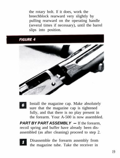
the rotary bolt. If it does, work thebreechblock rearward very slightly bypulling rearward on the operating handle(several times if necessary), until the barrelslips into position.
Install the magazine cap. Make absolutelysure that the magazine cap is tightenedfully, and that there is no play present inthe forearm. Your A-500 is now assembled.
PART BY PART ASSEMBLY - If the forearm,recoil spring and buffer have already been dis-assembled (as after cleaning) proceed to step 2.
Disassemble the forearm assembly fromthe magazine tube. Take the receiver in
19

hand and unscrew and remove themagazine cap. Remove the forearm fromthe magazine tube by sliding it forward offthe magazine tube.
Position the recoil spring and the forearmbuffer on the magazine tube. (The forearmbuffer goes on first, followed by the recoilspring.) Position them forward with theleading edge of the spring at the frontedge of the magazine tube.
Hold the receiver and the magazine tubelevel, and at the same time position thebarrel with the guide ring over themagazine tube, and the barrel extension atthe receiver opening. The lower edge ofthe barrel extension guide must be behindthe forearm buffer (See Figure 5).
Slide the barrel rearward seating the barrelextension rails in the receiver tracks. Thebarrel extension may hang up slightlywhere the extension contacts thebreechblock. If it does, position the gunvertically (barrel up) and pull rearward onthe operating handle, until the extensionslips into position.
Slide the forearm onto the magazine tube(over the recoil spring and forearm buffer)
20

and tighten down the magazine capsnugly. Make absolutely sure that themagazine cap is tightened fully, and thatthere is no play present in the forearm.Your A-500 is now fully assembled.
Disassembly of Barrel andForearm Assembly
CHECK YOUR GUN CAREFULLY TO BEABSOLUTELY CERTAIN THAT THECHAMBER, FEED MECHANISM ANDMAGAZINE CONTAIN NO SHELLS.
Disassembly of the barrel is important for
21
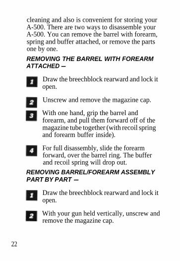
cleaning and also is convenient for storing yourA-500. There are two ways to disassemble yourA-500. You can remove the barrel with forearm,spring and buffer attached, or remove the partsone by one.
REMOVING THE BARREL WITH FOREARMATTACHED -
Draw the breechblock rearward and lock itopen.
Unscrew and remove the magazine cap.
With one hand, grip the barrel andforearm, and pull them forward off of themagazine tube together (with recoil springand forearm buffer inside).
For full disassembly, slide the forearmforward, over the barrel ring. The bufferand recoil spring will drop out.
REMOVING BARREL/FOREARM ASSEMBLYPART BY PART -
Draw the breechblock rearward and lock itopen.
With your gun held vertically, unscrew andremove the magazine cap.
22

Remove the forearm by pulling it forwardand off of the magazine tube.
Slide the barrel off of the magazine tube,disengaging the barrel extension from thereceiver. At this point the forearm bufferand barrel spring are free to come off theend of the magazine tube.
For convenience in casing and transportingthe dismantled gun, return the recoilspring, forearm buffer and forearm to theirpositions on the magazine tube andreinstall the magazine cap. You will thenhave two compact units: the barrel, andthe action with forearm and stock.
AFTER THE BARREL HAS BEEN REMOVEDFROM YOUR GUN, LEAVE THEBREECHBLOCK IN THE OPEN POSITION DONOT PRESS THE BOLT RELEASE BUTTON Ifthe breechblock is released forward with thebarrel removed, the operating handle will bedriven against the edge of the ejection port,which will cause damage to the receiver.
Loading Procedures
There are two basic methods for initially gettinga loaded shell into the chamber of your A-500.
23

First, the shell can be directly loaded throughthe ejection port. Second, a shell can be loadedmanually from the magazine. In both cases, themagazine must be loaded to automatically chambera subsequent shell. Loading the magazine andmagazine capacity is also detailed below.
CAUTION: AT ALL TIMES DURING THELOADING PROCEDURE, BE SURE YOURMUZZLE IS POINTING IN A SAFEDIRECTION AND THE “SAFETY” IS IN THE“ON SAFE” POSITION.
REMEMBER: DO NOT PUT A 20 GAUGESHELL IN A 12 GAUGE SHOTGUN NEVERSTORE SHELLS OF MIXED GAUGES IN ACOMMON CONTAINER OR IN YOUR l
POCKETS. See caution number 8 on page 6 ofthis booklet for an explanation.MAGAZINE CAPACITY - With the three shotadapter installed, the magazine will hold TWO2 3/4" or 3-inch shells. With the three shotadapter removed, the magazine holds FOUR2 3/4" or THREE 3-inch shells.
LOADING THE CHAMBER THROUGH THEEJECTION PORT -
1 After making sure the “safety” is “on safe,”pull the operating handle to the rear untilthe breechblock locks in the open position.Visually inspect the chamber, carrier, and
24

magazine to make sure they are clear ofany obstructions.
While pointing the muzzle in a safe direction,hold your A-500 with the ejection port up, andinsert a cartridge of the proper gauge throughthe ejection port into the open breech (SeeFigure 6). Press the breechblock releasebutton. KEEP YOUR FINGERS CLEAR OFTHE EJECTION PORT This will automat-ically cause the shell to be picked up anddelivered to the chamber correctly Thechamber is now loaded.
With the chamber loaded, load themagazine to full capacity as explainedbelow under “Loading the Magazine.”
25
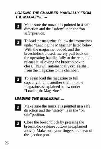
LOADING THE CHAMBER MANUALLY FROMTHE MAGAZINE -
Make sure the muzzle is pointed in a safedirection and the “safety” is in the “onsafe” position.
To load the magazine, follow the instructionsunder “Loading the Magazine” listed below.With the magazine loaded, and thebreechblock closed, merely pull back onthe operating handle, fully to the rear, andrelease it, allowing the breechblock toclose. This will automatically cycle a shellfrom the magazine to the chamber.
To again load the magazine to fullcapacity, thumb another shell into themagazine as explained below under“Loading the Magazine.”
26
Make sure the muzzle is pointed in a safedirection and the “safety” is in the “onsafe” position.
Close the breechblock by pressing thebreechblock release button (as explainedabove). Make sure your fingers are clear ofthe ejection port.

Insert a shell, of the proper gauge, throughthe loading port at the bottom of thereceiver, up into the magazine, using yourthumb to position it fully forward in themagazine tube (See Figure 7). Repeat thisprocedure until the magazine is fullyloaded.
CAUTION: WHENEVER A SHELL HAS BEENCYCLED INTO THE CHAMBER -AUTOMATICALLY OR MANUALLY - THESHOTGUN IS READY TO FIRE BY SIMPLYMOVING THE “SAFETY” TO THE OFF SAFEPOSITION.
27

Unloading your A-500
CAUTION: WHENEVER UNLOADING, ALWAYSBE CERTAIN THAT THE MUZZLE IS POINTEDIN A SAFE DIRECTION AND THAT THE“SAFETY” IS IN THE “ON SAFE” POSITION.
The recommended way to unload the A-500 issimply to grasp the operating handle and cyclethe action until all rounds are ejected.The magazine can be unloaded manually byreaching inside the loading port with your indexfinger, and simultaneously pressing in on thebottom of the carrier and pressing the carrierlatch (See Figure 17 on page 46). Release andremove one shell at a time from the magazine,until empty.ALWAYS INSPECT THE CHAMBER, ACTION,CARRIER AND MAGAZINE VERY CAREFULLYAFTER UNLOADING TO BE SURE ALL LIVEROUNDS ARE CLEARED FROM THE GUN.
Breech Remains Open After theLast Shot
The breech of the A-500 remains open, with thebreechblock locked to the rear, after the last shot
28

has been fired. This allows convenient and fastreloading as follows:
Place the “safety” in the “on safe” position.
Drop an appropriate shell into the openbreech.
Close the action by depressing the.breechblock release button.
Load the magazine as explained aboveunder “Loading the Magazine” on page 26.
EVEN WITH THE BREECH LOCKED OPENAFTER SHOOTING, DO NOT ASSUME YOURSHOTGUN IS UNLOADED. ALWAYS INSPECTTHE CHAMBER, CARRIER AND MAGAZINETO BE SURE THEY CONTAIN NO CARTRIDGES.THEN, REMEMBER TO ALWAYS TREAT ANYGUN AS IF IT WAS LOADED. ALWAYSHANDLE YOUR SHOTGUN WITH CAUTION.
Operation of the Magazinecut-off
The magazine cut-off lever is located at the frontend of the left side of the receiver. This cut-offhas the purpose of locking the shells in themagazine so that they will not feed into the
29

chamber. This permits you to quickly change theload in the chamber of the gun without going tothe trouble of unloading the whole magazine. Forinstance, in this way a duck load can quickly be takenout and a goose load inserted, if the need arises.
To operate the magazine cutoff, merely manipulatethe lever to the “MC” or “R” positions. The “MC”position engages the magazine cutoff (See FigureS-A). The “R” position (See Figure S-B) places themagazine in conventional repeater position,chambering a shell from the magazine each timethe breechblock cycles rearward (as when youshoot or manually cycle the breechblock).
Also, with the magazine cutoff in operation, and withthe chamber empty and the breechblock locked inthe rearward position, a loaded shell may be

instantly delivered from the magazine to the cham-ber by merely moving the lever from the “MC” posi-tion (magazine cutoff), to the “R (repeater) position.When the breechblock is locked rearward, BECAREFUL TO KEEP YOUR FINGERS CLEAR OF THELOADING PORT AND EJECTION PORT WHENMOVING THE LEVER FROM “MC” TO “R"
Full Disassembly: Trigger Groupand Breech Bolt
NOTE: All current production A-500 shotgunshave an improved trigger group assembly. Youcan confirm this by the letter ‘H’ stamped onthe trigger guard (See Figure 10).If your trigger guard does not have the letter “H”stamped on it then please contact our BrowningService Department toll tree at 1-800-322-4626for information on how to get the improvedtrigger assembly installed on your A-500.
If a malfunction occurs, or if the action becomesexcessively dirty, it is advisable to disassemblethe action for a complete cleaning as explainedbelow. Detailed cleaning procedures are outlinedunder “Cleaning and Maintenance” on page 54.Full disassembly involves removal of thebreechblock assembly and the trigger group.Any disassembly beyond this should only be
31
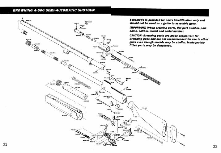

Parts List
PART NO.P014001P014005P014008P0l4012P014016
P014020P0l4025
*P0l4030P0l4034P0l4038
*P0l4044-P0l4048*P014052*P0l4056P0l4060P0l4065P0l4070
*P0l4076*P0l4084‘PO14089P0l4095
* P014101P0l4105P0l4110
*P0l4115P0l4120
*P0l4125
P0l4130
P0l4134
P0l4138*P0l4144P0l4148P0l4155P0l4160P0l4164P0l4l68P0l4172P0l4178P0l4182P0l4186
DESCRIPTIONAction Spring Front (2)Action Spring Guide (2)Action Spring Guide PinAction Spring Guide Washer (2)ActIon Spring Rear (2)Barrel ExtensionBarrel SpringBo l tBolt Cam PinBolt SpringBreechblockBreechblock BufferBreechblock Buffer CoreBreechblock LeverBreechblock Lever PinBreechblock Lever SpringBuffer Rings (9)Butt StockCarrierCarrier DugCarrier Dug PinCarrier & Carrier Dug SpringCarrier PinCarrier PinCirclip (2)Carrier Latch P0l4302Carrier Latch Spring P0l4308Cartridge Stop (Breechblock *¡P014315Release Button) *p0l4320Cartridge Stop & Carrier Latch *PO14324Pin PO14328Cartridge Stop & Carrier Latch PO14332Pin ClipCartridge Stop Spring
*P011340PO14344
Disconnector POl4350Disconnector Pin PO14354Ejector PO14358Extractor ‘PO14364Extractor Inner Spring PO14370Extractor Outer Spring PO14375Extractor Pin POl4360Firing Pin PO14385Firing Pin Cover POl4390Firing Pin Spring PO14395
l PART NO.PO14190
*PO14196P014204PO14210
-PO14215PO14220PO14225PO14230PO14234PO14240PO14245PO14246PO14254
P0l4258
P0l4262P0l4268P0l4274P0l426oP0l4266P0l4290P0l4294
PART NAMEFiring Pin Stop PinForearmFront RingFront Sight.HammerHammer PinMagazine CapMagazine Cap RetainerMagazine Cap with EyeletMagazine CuttoffMagazine Cutloff PinMagazine Cuttoff PlungerMagazine Cuttoff PlungerSpringMagazine Cuttoff PlungerSpring RetainerMagazine FollowerMagazine SpringMagazine Spring RetainerMagazine Three Shot AdaptorMainspringMainspring GuideMainsprig Guide PinHammerOperating HandleRear RingReceiver with TubeSafetySafety PlungerSafety Plunger SpringSafety Spring Stop PinSearSear PinStock ScrewStock Screw Lock WasherStock Screw WasherTriggerTrigger GuardTrigger Guard Pin SleeveTrigger Guard Retaining NutTrigger Guard Retaining ScrewTrigger PinTrigger Spring
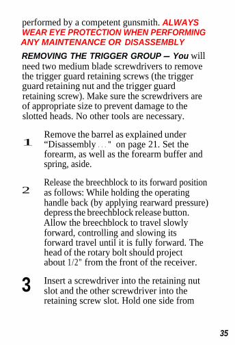
performed by a competent gunsmith. ALWAYSWEAR EYE PROTECTION WHEN PERFORMINGANY MAINTENANCE OR DISASSEMBLY
REMOVING THE TRIGGER GROUP - You willneed two medium blade screwdrivers to removethe trigger guard retaining screws (the triggerguard retaining nut and the trigger guardretaining screw). Make sure the screwdrivers areof appropriate size to prevent damage to theslotted heads. No other tools are necessary.
1Remove the barrel as explained under“Disassembly . . . ” on page 21. Set theforearm, as well as the forearm buffer andspring, aside.
2Release the breechblock to its forward positionas follows: While holding the operatinghandle back (by applying rearward pressure)depress the breechblock release button.Allow the breechblock to travel slowlyforward, controlling and slowing itsforward travel until it is fully forward. Thehead of the rotary bolt should projectabout 1/2" from the front of the receiver.
3 Insert a screwdriver into the retaining nutslot and the other screwdriver into theretaining screw slot. Hold one side from
35

turning while unscrewing the opposite side(See Figure 9).
Remove the retaining nut and screw fromthe receiver.
With the gun inverted (trigger guard up),grasp the trigger guard and pull it up,forward and out from the receiver (SeeFigure 10). DO NOT DISASSEMBLE THETRIGGER GROUP BEYOND THIS POINTPerform all cleaning with the trigger groupkept intact as an assembly
REMOVING THE BREECHBLOCK - Normalprocedure is to remove the trigger group first, asexplained previously.

1
2
Remove the operating handle as follows:With your left hand, push on the bolt headmoving the breechblock about 1/2" backinto the receiver, lining up the operatinghandle with the notch at the bottom frontof the ejection port (See Figure ll-A). Withyour right hand grasp the operating handleand pull it outward, removing it from thebreechblock (See Figure ll-B).
The breechblock will now be able to moveforward about another 1/2". Again, pushrearward on the bolt head, depressing thebreechblock back into the receiver about1/4". With your right hand, reach in with afinger and push on the breechblock lever
37


found on the bottom side of the breechblock(See Figure 12). The breechblock lever servesto retain the breechblock in the receiver.(SPECIAL NOTE: It is possible to removethe breechblock first before removing thetrigger group. You will need simultaneouslypush rearward 1/4" on the breechblockand “reach” in through the opening at thefront of the carrier to depress thebreechblock lever, using the eraser end ofa pencil, a small wood dowel, ascrewdriver, or other similar object.)
With the breechblock lever pressed, removethe breechblock forward, out of the frontof the receiver. The action springs will stayattached to the breechblock, projectingfrom the rear The breechblock is now fullyremoved DO NOT DISASSEMBLE THEBREECH BLOCK BEYOND THIS POINT.
Reassembly: Trigger Group andBreechblock
REINSTALLING THE BREECHBLOCKASSEMBLY -
1 Insert the breechblock into the receiveropening, action springs first. The guides on
39

the breechblock must fit in the receiver tracks.Make sure the front action springs fit overthe ends of the action spring guides (SeeFigure 13). Push the breechblock in farenough that the breechblock lever engages,holding the breechblock in the receiver.
Simultaneously push back on the breechblockwhile depressing the breechblock releasebutton until the notch in the ejection portlines up with the operating handle recesson the breechblock. Make sure that theaction springs are compressed inside therecesses in the breechblock, and that theends of the action spring guides start into
40

the recesses in the breechblock withoutkinking the front action springs.
Insert the operating handle into the recess(See Figure 11-A on page 37). Thebreechblock is now installed.
REINSTALLING THE TRIGGER GROUP -
Reinsert the trigger group into the bottomof the receiver, moving it rearward toassure correct location of the rear pins intothe holes in the receiver. Then start at theback and hinge the trigger guard forward(See Figure 14).
41
Line up the hole in the trigger guard withthe holes on each side of the receiver.Insert the trigger guard retaining nutcompletely through the receiver. Start theretaining screw with your fingers and tightenusing two screwdrivers, one for eachslotted head on each side of the receiver.
Three-Shot Magazine Adapter
The following instructions are for disassembly ofthe magazine, and the removal or installation ofthe three-shot magazine adapter. Steps 1-8 detailmagazine disassembly, and are the same forboth removal and installation of the three-shotadapter. Steps 9-A and 9-B explain reassembly ofthe magazine with or without the three shot adapter.
The A-500 shotgun is delivered with the three-shot magazine adapter installed in the magazine,limiting magazine capacity to two shells -allowing three shots total in compliance withfederal migratory bird regulations. If you do notwish to be limited to three shots - when it isnot required by law - you can remove orreinstall the three-shot adapter (plug) as follows:ALWAYS WEAR PROTECTIVE SAFETYGLASSES DURING THIS OPERATION.
42

Unscrew the forearm cap and remove theforearm, BARREL, forearm buffer and recoilspring from the gun as explained under“Disassembly of Barrel and ForearmAssembly” on page 21. UNDER NO CIRCUM-STANCES SHOULD YOU PERFORM THEFOLLOWING PROCEDURES WITH THEBARREL ATTACHED.
2 Reinstall the magazine cap on the magazinetube approximately one turn engaging atleast ONE FULL TURN OF THREADS solidly.
3Release the breechblock forward slowly bypressing the breechblock release button andslowly allowing the breechblock to travelforward. Do this by pressing the button withone hand and offering resistance on the oper-ating handle with the other hand, gentlyeasing it forward to the fully forward position.
4 Pull back approximately 1/4" of an inchon the operating handle. With your otherhand insert two 2 3/4" (or two 3-inchmagnum shells) into the magazine if youare removing the three-shot adapter ORinsert four 2 3/4" shells (or three 3-inchmagnums) if the three-shot adapter wasremoved previously and you arereinstalling it. Position an additional shellas if you were going to insert it into the
43

magazine (it will stop only partiallyinserted because of the full magazine).
Apply steady, hard pressure on the shell,pushing all the shells forward in the magazineuntil the magazine spring retainer isdislodged from its compressed fitting at theend of the magazine (See Figure 15). Youwill feel forward movement of the shells inthe magazine when it is dislodged.
IF IT WILL NOT DISLODGE WITHSTEADY PRESSURE you may have towork the last shell in and out to increaseforce on the shells in the magazine.
If this also fails to dislodge the magazine springretainer, place another shell behind the one

partially inserted and apply increasedpressure with the palm of your hand, orstrike the back of the last shell with thepalm of your hand until the retainer isdislodged (See Figure 16).NOT USE ANY OTHER OBJECT THANTHE PALM OF YOUR HAND TO APPLYPRESSURE TO THE LAST SHELL.
With the retainer dislodged, IMMEDIATELYREMOVE THE SHELLS FROM THEMAGAZINE. DO NOT UNSCREW THEMAGAZINE CAP WITH SHELLS IN THEMAGAZINE. Remove the shells by firstpulling back approximately 1/4" on theoperating handle. Then release the shellsfrom the magazine by reaching inside the
45

loading port and simultaneously pressingin on the bottom of the carrier andpressing the carrier latch with your finger(See Figure 17). Release and remove oneshell at a time from the magazine.IMMEDIATELY PUT ALL THE SHELLSAWAY IN YOUR AMMUNITIONSTORAGE AREA - AWAY FROM YOURA-500 AND OTHER GUNS.
the Shells Dire
46
Carefully unscrew the magazine cap fromthe magazine. CAUTION: THE MAGAZINESPRING IS UNDER TENSION AND WILLFORCE OUT THE RETAINER, THREESHOT ADAPTER AND THE SPRINGITSELF UNLESS CARE IS TAKEN. Slowly

lift the magazine cap off of the magazine.At the same time, catch the spring withyour other hand as it begins to come out(See Figure 18). If already installed, thethree shot adapter will be on top of themagazine spring.
Remove the spring and adapter, if present,from the magazine tube. Remove themagazine spring retainer from the inside ofthe magazine cap. The magazine followercan be removed by pointing the magazinetube downward and dumping it out.
REASSEMBLY WITH THE THREE-SHOTMAGAZINE ADAPTER INSTALLED
To reassemble the magazine with the47
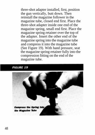
three-shot adapter installed, first, positionthe gun vertically, butt down. Thenreinstall the magazine follower in themagazine tube, closed end first. Place thethree-shot adapter inside one end of themagazine spring, small end first. Place themagazine spring retainer over the top ofthe adapter. Insert the other end of themagazine spring into the magazine tubeand compress it into the magazine tube(See Figure 19). With hand pressure, seatthe magazine spring retainer fully into thecompression fitting on the end of themagazine tube.
48

REASSEMBLY WITHOUT THE THREE-SHOT MAGAZINE ADAPTER.
Reassembly of the magazine without thethree-shot adapter is identical to step 9-Awith one exception: after inserting themagazine follower into the magazine tube,place the magazine spring retainer directlyon the end of the magazine spring. Theninsert the other end of the magazine springinto the magazine tube and compress it intothe magazine tube. With hand pressure,seat the magazine spring retainer fully intothe compression fitting on the end of themagazine tube.
Reassembly of the magazine, and removal/installation of the three-shot magazine adapter isnow completed. To prepare for replacing thebarrel and forearm on your A-500, pull theoperating handle on the breechblock fullyrearward, locking the breechblock back. You arenow ready to reinstall the barrel/forearmassembly to the receiver as outlined in“Assembly Procedures-Barrel to Receiver” onpage 16.
49

Invector Interchangeable ChokeSystem
All A-500 shotgun barrels have been threaded toaccept the Browning Invector InterchangeableChoke System. You may confirm this by lookingon the right side of your barrel where thespecifications are inscribed, and where thechoke markings are normally located. The wordINVECTOR denotes that the barrels arethreaded. The degree of choke tube is indicatedtwice on each choke tube: Inscribed on the sideof the tube, and indicated with a “notch’ codeon the top rim of the tube.Invector Choke Tubes are made with temperedsteel and are fully compatible with all FACTORYAMMUNITION (loaded in compliance withSAAMI specifications) including Magnum leadand steel shot loads and rifled slug loads.
DO NOT FlRE THIS SHOTGUN WITHOUT HAV-ING AN INVECTOR CHOKE TUBE INSTALLEDPermanent damage may result to the threads.
DO NOT USE BROWNING INVECTOR CHOKETUBES IN ANY SHOTGUN BARRELS NOTSUPPLIED BY BROWNING. ALSO, DO NOTUSE ANY OTHER CHOKING DEVICE IN ANYSHOTGUN BARREL SUPPLIED BY BROWNING.USE ONLY CHOKE TUBES MARKED INVECTOR
50
CAUTION: WHENEVER HANDLING ANYSHOTGUN FOR THE PURPOSE OFREMOVING OR INSTALLING A CHOKlNGDEVICE, MAKE ABSOLUTELY CERTAIN THEGUN IS FULLY UNLOADED, AND THE BOLTOR BREECH IS OPEN! NEVER ATTEMPT TOREMOVE OR INSTALL A SHOTGUN CHOKINGDEVICE ON A LOADED FlREARM!
TUBE REMOVAL-
1
23
UNLOAD YOUR A-500 FULLY INSPECTTHE CHAMBER, FEED MECHANISMAND MAGAZINE TO MAKE SURE THEYDO NOT CONTAIN ANY SHELLS.
Open the action, locking it rearward, andplace the “safety” in the “on safe” position.
Use the Invector wrench to loosen thetube, turning it counterclockwise. Finger-twist the tube the rest of the way out ofthe barrel.
TUBE INSTALLATION
UNLOAD YDUR A-500 FULLY INSPECTTHE CHAMBER, FEED MECHANISMAND MAGAZINE TO MAKE SURE THEYDO NOT CONTAIN ANY SHELLS
51
2 Open the action and place the “safety” inthe “on safe” position.
3 Before installing a tube, check the internalchoke tube threads in the muzzle, as wellas the threads on the Invector choke tubeto be sure they are clean. Lightly oil thethreads with an oil like Browning Oil.
4Using your fingers screw the appropriatetube into the muzzle end of the barrel,tapered end first, notched end outward. Whenit becomes finger-tight, use the Invectorchoke wrench to firmly seat the tube.
THE INVECTOR CHOKE TUBE SHOULD BEPERIODICALLY CHECKED TO ASSURE THATIT IS TIGHT AND FlRMLY SEATED. BEFORECHECKING, FOLLOW THE SAFETYGUIDELINES OUTLINED ABOVE.
Replacement and additional tubes and wrenchesare available from your Browning dealer, or bywriting to the Browning Consumer Department,Route 1, Morgan, Utah 84050. (801) 543-3200.
Canadian customers please call or write toBrowning Canada Sports Ltd./Ltee, 3167 DeMiniac, St. Laurent Canada H4S 1S0 (514) 333-7261.INVECTOR CHOKE TUBE CODE - To identifyindividual Invector tubes, refer to theabbreviated indiciations on the side of the tube,
52

or use the identification mark(s) located on thetop rim of each tube (See Figure 20).
INVECTOR TUBE SELECTION
This chart shows lead/steel choke constrictiondesignations for each lnvector tube within eachgauge. Designation is listed lead first, then steel:for example, M/F means a certain tube shootsModified with lead shot and Full with steel shot.Tubes listed are also available as accessories.
12 Gauge lead/Steel XF/** F/* lM/F† M/F† IC/M S/IC† C/IC†
Tube Code: XF-Extra Full, F-Full, IM-Improved Modified, M-Modified,K-Improved Cylinder, S-Skeet C-Cylinder*Do not use with steel shot. Using an over-tigbt choke constriction withsteel shot will result in an ineffective, "b lown" pattern.**Extra Full Special with knurled rim and no rim code. Do not use withsteel shot.When more than one choke designation is listed for a given steel shotpattern, use the more open choke listed for high velocity larger shot sizesteel shot loads.
Use of Extra Barrels
On all Browning A-500 shotguns, barrels of thesame gauge are completely interchangeable, andno special fitting is required. Thus, by merelybuying another barrel of a different length, orfor a different purpose (such as a Buck Specialbarrel), and using the appropriate lnvector choketube, you have acquired the utility of anothergun at a traction of the cost of a new gun; aduck gun becomes a fine upland game gun, apheasant gun becomes a rifled slug deer gun.
Sight Adjustment for BuckSpecial Barrels
Buck Special barrels are equipped with aprecision rear sight which is screw adjustable forboth horizontal and vertical correction.WINDAGE ADJUSTMENT - To move point ofimpact to the RIGHT, loosen the small screw onthe right side of the sight. Then tighten the smallscrew on the left side of the sight. To move pointof impact to the LEFT loosen the small screw onthe left side of the sight and tighten the screwon the right side. This is a process of trial anderror. Make small adjustments then check the
54point of impact.

VERTICAL ADJUSTMENT - Adjustment of thesight is controlled by the screw located on top ofthe sight. To RAISE the point of impact, turn thescrew in a counterclockwise direction. ToLOWER the point of impact, turn the screw in aclockwise direction. Vertical adjustment is also aprocess of trial and error.
Cleaning and MaintenanceSuggestions
You should clean your A-500 whenever it becomesexcessively dirty - and perform a thoroughcleaning at least once a year. The barrel shouldbe cleaned, and the action wiped clean andoiled after every day of shooting. If a malfunctionoccurs, perform a thorough cleaning, to see if itsolves the problem, before seeking the servicesof a Browning Recommended Service Center,the Browning Service Facility in Arnold,Missouri, or a competent gunsmith.Normal maintenance can be accomplished withthe barrel still attached to the receiver (oilingand wiping down). More careful cleaningrequires removal of only the barrel from thereceiver (cleaning the barrel). A completecleaning requires removal of the breechblockand trigger group.
55

PERIODIC OILING - Ordinary good judgmentwill indicate that the metal parts of the gunshould receive a light film of oil after the gunhas been exposed to weather or handling.Occasionally, a small drop of oil may be placedon each receiver track in which the barrelextension guides and breechblock run duringoperation (See Figure 21). This will help torelieve friction and ensure smooth operation.
Also, lightly lubricate the breechblock, rotarybolt and spring guides. DO NOT POUR LARGEQUANTITIES OF OIL INTO THE ACTION. Alarge excess of oil will run back into the wood ofthe stock and cause softening of the wood, withconsequential loosening of the stock.
56

CLEANING PROCEDURES - The correct pro-cedure for cleaning your A-500 shotgun is as follows:
BE CERTAIN YOUR SHOTGUNSMAGAZINE, FEED MECHANISM ANDCHAMBER ARE UNLOADED. PLACETHE “SAFETY” IN THE “ON SAFE”POSITION. ALWAYS WEARPROTECTIVE SAFETY GLASSESDURING ALL DISASSEMBLY ANDCLEANING PROCEDURES.
Remove the barrel so that it can becleaned from the breech end (See“Disassembly . . . ” on page 21).
Using a shotgun cleaning rod with tip andpatch large enough for a snug fit in thebore, insert the rod and patch in thebreech end of the barrel and run back andforth through the bore several times.Remove and wipe the Invector tube, tubethreads and barrel threads, and lightly oil.
Inspect the bore from both ends forleading by looking through bore towardlight. Leading will appear as dulllongitudinal streaks and is usually morepredominant near the muzzle and justforward of the chamber.
57
5 A normal amount of leading can beexpected with today’s high velocity loadsand improved wads but this is not serious.If or when leading should become heavy, itcan be removed with a brass bore brush.Make sure a choke tube is installed. Spraythe bore or the bore brush with a goodpowder solvent, and scrub the bore untilleading is removed. To prevent brassbristles from breaking off, the brush shouldbe pushed completely through the borebefore being withdrawn.
6After leading has been removed, the boreshould be wiped dry with a clean patch,and then a lightly oiled patch run throughit for preservation.
7 If .the gun has been exposed to much dust,dirt, mud or water, the principal workingparts should be wiped clean and lubricatedwith a light film of oil. Browning Oil isrecommended.
8 Remove the forearm buffer and recoilspring. Wipe the magazine tube clean ofall dirt and grit. Lightly oil and wipe dry
9When the action becomes excessivelydirty, remove the trigger group andbreechblock assembly from the receiver as
58
explained under “Full Disassembly . . . ” onpage 31. Clean with an oil such as BrowningOil or a gun solvent as necessary, using an oldtoothbrush to loosen any caked-on grime.Wipe the receiver cavity clean. Lightly oilthe cavity (aerosol Browning Oil is ideal)and wipe it dry. No further disassembly isrequired for cleaning.
Reassemble the trigger group, breechblock,and the barrel to the receiver. Then wipe allexposed metal surfaces with an oiled clothmaking sure to wipe your A-500 clean of allfinger marks where moisture will accumulate.
The barrel and action should be inspectedto assure that all cleaning patches havebeen removed and not inadvertently left inthe barrel or action.
The wood surfaces can also be wiped withBrowning Oil or they can be polished withany quality furniture wax (but not both).
DO NOT TAKE YOUR GUN’S ACTION APARTBEYOND THE EXTENT EXPLAINED IN THISMANUAL This is a specialized, finely fittedmechanism, and you may mar it for life by an attemptto disassemble the inner mechanism assemblies. Donot disassemble the breechblock and trigger groupmore than described. If further disassembly isrequired, take your gun to a Browning Recom-mended Service Center or a competent gunsmith. 59
Service or Repair
If your A-500 should require service or repairs,we suggest you first contact a local recommendedBrowning Firearms Service Center. YourBrowning Sporting Goods dealer can tell you theaddress of the Service Center nearest you, oryou may call or write our Consumer InformationDepartment in Morgan, Utah (801) 543-3200.Otherwise you may return your shotgun to ourown repair facility for servicing. The address is:
Browning Service Department3005 Arnold Tenbrook RoadArnold, Missouri 63010-9406Phone: 1-800-322-4626
Canadian Customers call or write:
Browning Canada Sports Ldt./Ltee,3167 De Miniac, St-Laurent, Quebec H4S 1S0(514) 333-7261
When returning your A-500 for servicing, pleasebe sure it is unloaded, and that it is packagedsecurely in a cardboard container. Under nocircumstances should ammunition be returned asit is against postal and most commerceregulations. YOU MUST ENCLOSE A LETTERWITH THE GUN that clearly describes thetrouble experienced and the repairs oralterations desired.
60
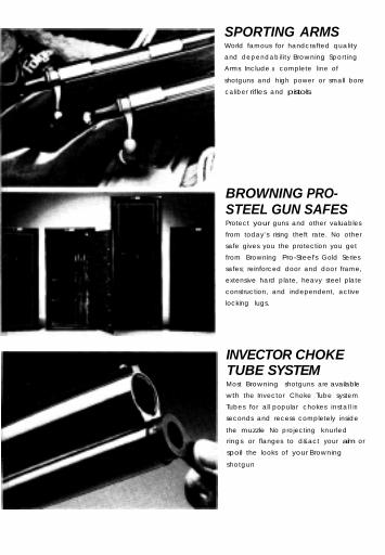
SPORTING ARMSWorld famous for handcrafted quality
and dependability Browning Sporting
Arms Include a complete line of
shotguns and high power or small bore
caliber rifles and pistols
BROWNING PRO-STEEL GUN SAFESProtect your guns and other valuables
from today’s rising theft rate. No other
safe gives you the protection you get
from Browning Pro-Steel's Gold Series
safes; reinforced door and door frame,
extensive hard plate, heavy steel plate
construction, and independent, active
locking lugs.
INVECTOR CHOKETUBE SYSTEMMost Browning shotguns are available
wth the Invector Choke Tube system
Tubes for all popular chokes install in
seconds and recess completely inside
the muzzle No projecting knurled
rings or flanges to d&act your aim or
spoil the looks of your Browning
shotgun

SPORTSMAN'S BOOTSPACKS AND WADERSBrowning boots are known for theircomfort and long wear. They’re builtfrom the finest materials and leatherswith features like Dual-Waterproof™construction found on all Nomad seriesGore-Tex® boots. A waterproof outershell and inner Gore-Tex® bootiedoubles your assurance of dry feet.You’ll cover more ground with lesseffort vearing a pair of our famouslightweight boots.
BROWNINGHOLSTERS ANDPISTOL CASES
ARCHERYACCESSORIESYou can completely outfit yourBrowning bow with accessories tomeet all types of hunting and target
situations. Specialty sights, quivers,arrow rests, bow cases, gloves and armguards are just a few of the accessories
offered.

SPORTSMAN'SCLOTHINGHunting, fishing, or treks to theshopping mall, you know that yourBrowning clothing will do its job well.For the sportsman who spends time inwet, cold weather, Browning has acomplete line of waterproof Gore-Tex®clothing. Hats, gloves and handsomeleather belts are also available.
ARCHERYEQUIPMENTBrowning has a complete line ofcompound bows suited for recreationand hunting. Handsome styling,coupled with exceptional speed andaccuracy is something you can counton with every Browning bow. There isa draw weight, draw length, and bowsize for nearly every shooter.
GUN CASESYour guns are well protected in aBrowning flexible gun case. Exteriorsof genuine leather, attractive vinyl,rugged canvas or tough, water-repellent Cordura nylon are availablefor nearly any size gun. Soft innerlinings protet your gun’s finish. Ourluggage cases are of scuff resistant,leather-textured vinyl and lined withpolyester fleece fabric, giving youunmatched protection for yourBrowning shotguns and rifles.

Other Browning Products
SPORTSMAN’SKNIVESThere i s a folding or fixed blade
Browning knife to match nearly every
requirement - including f i l let pocket
skinning and general uti l i ty style
knives Every Browning knife i s manu-
factured using the finest materials and
the most hand-pleasing designs Each
Browning knife i s distinctive in quality
and style the way a good knife should be
FISHING TACKLEYou'll catch more fish and have more
fun with a quality Browning fishing rod
or reel There’s a rod for every fishing
trip - from pack rods for traveling to
heavy rods for deep sea action Top
quality reefs come in sizes for
practically any fishing situation Also
choose from Browning's complete line
of quality accessories
BROWNING OILBrowning Oil is the best all-around oil
for your guns. It cleans, lubricates. and
protects metal and blueing. It is
designed to function in extreme
temperatures and provides excellent
anti-rust protection. Browning Oil is
also ideal for many other applications
including household, automotive, and
fishing tackle. Available in drip spout
or aerosol can.