wc bo0160448en 004 - wacker neuson corporation: login...
TRANSCRIPT
Light Tower
LTC 4L
OPERATOR’S MANUAL
0160448en 004
0706
0 1 6 0 4 4 8 E N


LTC 4L Table of Contents
1. Foreword 3
2. Safety Information 4
2.1 Laws Pertaining to Spark Arresters ...................................................... 42.2 Operating Safety .................................................................................. 52.3 Operator Safety while using Internal Combustion Engines .................. 62.4 Service Safety ...................................................................................... 72.5 Label Locations .................................................................................... 82.6 Safety and Operating Labels .............................................................. 10
3. Technical Data 16
3.1 Engine ................................................................................................ 163.2 Generator ........................................................................................... 173.3 Machine .............................................................................................. 17
4. Operation 18
4.1 Adjusting Lights .................................................................................. 184.2 Operating Lights ................................................................................. 194.3 Raising Tower (Manual Winch System) ............................................. 204.4 Lowering Tower (Manual Winch System) ........................................... 224.5 Control Panels - 50 Hz - Manual Winch System
(0009379, 0009485 Rev. 101 & lower) ............................................... 244.6 Control Panels - 50 Hz - Manual Winch System
(0009485 Rev. 102 & higher) ............................................................. 264.7 Starting ............................................................................................... 284.8 Automatic Shutdown .......................................................................... 284.9 Stopping ............................................................................................. 294.10 Emergency Stop Switch ..................................................................... 294.11 Derating .............................................................................................. 294.12 Receptacle - 50 Hz ............................................................................. 30
wc_bo0160448en_004TOC.fm 1

Table of Contents LTC 4L
5. Maintenance 31
5.1 Installing / Removing Light Fixtures ....................................................315.2 Replacing / Removing Bulbs ...............................................................325.3 Daily Inspection ...................................................................................325.4 Air Cleaner ..........................................................................................335.5 Engine Oil ............................................................................................335.6 Engine Maintenance ............................................................................345.7 Troubleshooting ...................................................................................355.8 Schematic for 50 Hz Metal Halide 4-Light Units-115 V
(0009379 Rev. 104 and higher) ...........................................................365.9 Schematic for 50 Hz Metal Halide 4-Light Units-115 V
(0009379 Rev. 102 and 103) ...............................................................385.10 Schematic for 50 Hz Metal Halide 4-Light Units-115 V
(0009379 Rev. 101 and lower) ............................................................405.11 Schematic for 50 Hz Metal Halide 4-Light Units-230 V
(0009485 Rev. 104 and higher) ...........................................................425.12 Schematic for 50 Hz Metal Halide 4-Light Units-230 V
(0009485 Rev. 102 and103) ................................................................445.13 Schematic for 50 Hz Metal Halide 4-Light Units-230 V
(0009485 Rev. 101 and lower) ............................................................465.14 Generator Capacitor Excitation Schematic 50 Hz ...............................485.15 Engine Wiring - Lombardini .................................................................495.16 Control Panel Wiring ...........................................................................50
wc_bo0160448en_004TOC.fm 2
wc_tx000001gb.fm 3
CALIFORNIA
Proposition 65 Warning:
Engine exhaust, some of its constituents, and certain vehiclecomponents, contain or emit chemicals known to the State ofCalifornia to cause cancer and birth defects or other reproductiveharm.
1. Foreword
This manual provides information and procedures to safely operateand maintain this Wacker model. For your own safety and protectionfrom injury, carefully read, understand and observe the safetyinstructions described in this manual.
Keep this manual or a copy of it with the machine. If you lose thismanual or need an additional copy, please contact WackerCorporation. This machine is built with user safety in mind; however,it can present hazards if improperly operated and serviced. Followoperating instructions carefully! If you have questions about operatingor servicing this equipment, please contact Wacker Corporation.
The information contained in this manual was based on machines inproduction at the time of publication. Wacker Corporation reserves theright to change any portion of this information without notice.
All rights, especially copying and distribution rights, are reserved.
Copyright 2006 by Wacker Corporation.
No part of this publication may be reproduced in any form or by anymeans, electronic or mechanical, including photocopying, withoutexpress written permission from Wacker Corporation.
Any type of reproduction or distribution not authorized by WackerCorporation represents an infringement of valid copyrights and will beprosecuted. We expressly reserve the right to make technicalmodifications, even without due notice, which aim at improving ourmachines or their safety standards.
WARNING
Safety Information LTC 4L
2. Safety Information
This manual contains DANGER, WARNING, CAUTION, and NOTEcallouts which must be followed to reduce the possibility of personalinjury, damage to the equipment, or improper service.
This is the safety alert symbol. It is used to alert you to potentialpersonal injury hazards. Obey all safety messages that follow thissymbol to avoid possible injury or death.
DANGER indicates an imminently hazardous situation which, if notavoided, will result in death or serious injury.
WARNING indicates a potentially hazardous situation which, if notavoided, could result in death or serious injury.
CAUTION indicates a potentially hazardous situation which, if notavoided, may result in minor or moderate injury.
CAUTION: Used without the safety alert symbol, CAUTION indicatesa potentially hazardous situation which, if not avoided, may result inproperty damage.
Note: Contains additional information important to a procedure.
2.1 Laws Pertaining to Spark Arresters
Notice: State Health Safety Codes and Public Resources Codesspecify that in certain locations spark arresters be used on internalcombustion engines that use hydrocarbon fuels. A spark arrester is adevice designed to prevent accidental discharge of sparks or flamesfrom the engine exhaust. Spark arresters are qualified and rated bythe United States Forest Service for this purpose.
In order to comply with local laws regarding spark arresters, consultthe engine distributor or the local Health and Safety Administrator.
DANGER
WARNING
CAUTION
wc_si000146gb.fm 4

LTC 4L Safety Information
2.2 Operating Safety
Familiarity and proper training are required for the safe operation ofequipment. Equipment operated improperly or by untrained personnelcan be dangerous. Read the operating instructions contained in boththis manual and the engine manual and familiarize yourself with thelocation and proper use of all controls. Inexperienced operators shouldreceive instruction from someone familiar with the equipment beforebeing allowed to operate the machine.
2.2.1 The area immediately surrounding the Light Tower should be clean,neat, and free of debris.
2.2.2 ALWAYS be sure the machine is on a firm, level surface and will nottip, roll, slide, or fall while operating.
2.2.3 NEVER start a unit in need of repair.
2.2.4 Lower the tower when not in use, or if high winds or electrical stormsare expected in the area.
2.2.5 The tower extends up to 8.8 m (29 ft.). Make sure area above trailer isopen and clear of overhead wires and obstructions.
2.2.6 The bulbs become extremely hot in use! Allow the bulb and fixture tocool 10–15 minutes before handling.
2.2.7 Keep the area behind the trailer clear of people while raising andlowering the mast! Never raise, lower or turn the mast while unit isoperating!
2.2.8 The trailer must be leveled and the outriggers extended before raisingthe tower. The outriggers must remain extended while the tower is up.
2.2.9 If for any reason any part of the mast hangs up or the winch cabledevelops slack while raising or lowering the tower, STOP immediately!Contact an authorized WACKER service representative.
2.2.10 NEVER remove the mast locking pin while the tower is up!
2.2.11 NEVER use the machine if the insulation on the electrical cord is cut orworn through.
2.2.12 NEVER operate the lights without the protective lens cover in place orwith a lens cover that is cracked or damaged!
2.2.13 NEVER adjust the mast while the unit is operating.
2.2.14 NEVER raise the mast or operate the Light Tower in high winds.
2.2.15 NEVER connect machine to other power sources, such as supplymains of power companies.
2.2.16 ALWAYS replace or repair electrical components with componentsthat are identical in rating and performance as the original component.
WARNING
wc_si000146gb.fm 5
Safety Information LTC 4L
2.3 Operator Safety while using Internal Combustion Engines
Internal combustion engines present special hazards during operationand fueling. Read and follow the warning instructions in the engineowner’s manual and the safety guidelines below. Failure to follow thewarnings and safety guidelines could result in severe injury or death.
2.3.1 NEVER operate the machine indoors unless exhaust fumes can beadequately ventilated.
2.3.2 DO NOT fill or drain the fuel tank near an open flame, while smoking,or while the engine is running.
2.3.3 ALWAYS refill the fuel tank in a well-ventilated area.
2.3.4 DO NOT touch or lean against hot exhaust pipes.
2.3.5 ALWAYS replace the fuel tank cap after refueling.
2.3.6 DO NOT remove radiator cap when the engine is running or hot. Theradiator fluid is hot and under pressure and may cause severe burns!
2.3.7 DO NOT use gasoline or other types of fuels or flammable solvents toclean parts, especially in enclosed areas. Fumes from fuels andsolvents can become explosive.
2.3.8 ALWAYS keep the area around the muffler free of debris such asleaves, paper, cartons, etc. A hot muffler could ignite the debris andstart a fire.
DANGER
wc_si000146gb.fm 6

LTC 4L Safety Information
2.4 Service Safety
HIGH VOLTAGE! This unit uses high voltage circuits capable ofcausing serious injury or death. Only a qualified electrician shouldtroubleshoot or repair electrical problems occurring in this equipment.
2.4.1 ALWAYS replace the safety devices and guards after repairs andmaintenance.
2.4.2 Before servicing the Light Tower, make sure the engine start switch isturned to OFF, the circuit breakers are open (off), and the negativeterminal on battery is disconnected. NEVER perform even routineservice (oil/filter changes, cleaning, etc.) unless all electricalcomponents are shut down.
2.4.3 DO NOT allow water to accumulate around the base of the machine.If water is present, move the machine and allow the machine to drybefore servicing.
2.4.4 DO NOT service the machine if your clothing or skin is wet.
2.4.5 ALWAYS keep hands, feet, and loose clothing away from the movingparts on the generator and engine.
2.4.6 ALWAYS keep the machine clean and labels legible. Replace allmissing and hard-to-read labels. Labels provide important operatinginstructions and warn of dangers and hazards.
2.4.7 ALWAYS make sure slings, chains, hooks, ramps, jacks and othertypes of lifting devices are attached securely and have enough weight-bearing capacity to lift or hold the machine safely. Always remainaware of the location of other people around when lifting the machine.
2.4.8 ALWAYS turn off the light circuit breakers and shut down the enginebefore disconnecting the light fixtures or changing the light bulbs.
WARNING
wc_si000146gb.fm 7

Safety Information LTC 4L
2.5 Label Locations
wc_si000146gb.fm 8

LTC 4L Safety Information
wc_si000146gb.fm 9

Safety Information LTC 4L
2.6 Safety and Operating Labels
Wacker machines use international pictorial labels where needed.These labels are described below:
Ref. Label Meaning
A DANGER! A non-secured, falling mast will cause serious injury or death if a person is hit. To secure mast, verify automatic locking pin has engaged to secure tower upright.
B WARNING! Avoid crushing area.
C WARNING! Completely lower tower before tilting mast. Tilting an extended mast could cause serious injury or death.
D DANGER! Contact with overhead electrical power lines will cause serious injury or death. Do not position Light Tower under electrical power lines.
wc_si000146gb.fm 10

LTC 4L Safety Information
E CAUTION! Lifting point
F WARNING! Secure mast in transport lock before lifting or towing. A loose swinging mast could cause personal injury or machine damage.
G DANGER! Asphyxiation hazard. Read the Opera-tor’s Manual for instructions. No sparks, flames, or burning objects near machine. Stop the engine before adding fuel. Use only diesel fuel.
H DANGER! Asphyxiation hazard. Read the Opera-tor’s Manual for instructions. No sparks, flames, or burning objects near machine. Stop the engine before adding fuel. Use only diesel fuel.
DANGER! Contact with overhead electrical power lines will cause serious injury or death. Do not position Light Tower under electrical power lines.
WARNING! Completely lower tower before tilting mast. Tilting an extended mast could cause serious injury or death.
I DANGER! Electrical storage device within. Contact a qualified electrician for service or to open electrical box. Electric shock will cause serious injury or death.
Ref. Label Meaning
wc_si000146gb.fm 11

Safety Information LTC 4L
K WARNING! Stand clear of front and rear of machine when mast is being tilted up or down.
L WARNING! Hot surface!
M A nameplate listing the model number, item number, revision number, and serial number is attached to each unit. Please record the information found on this plate so it will be available should the nameplate become lost or damaged. When ordering parts or requesting service information, you will always be asked to specify the model number, item number, revision number, and serial number of the unit.
N WARNING! Ultraviolet radiation from lamp can cause serious skin and eye irritation. Use only with provided undamaged lens cover and fixture.
Ref. Label Meaning
wc_si000146gb.fm 12

LTC 4L Safety Information
O
Ref. Label Meaning
wc_si000146gb.fm 13

Safety Information LTC 4L
Q
Ref. Label Meaning
Manual Winch System
wc_si000146gb.fm 14
LTC 4L Safety Information
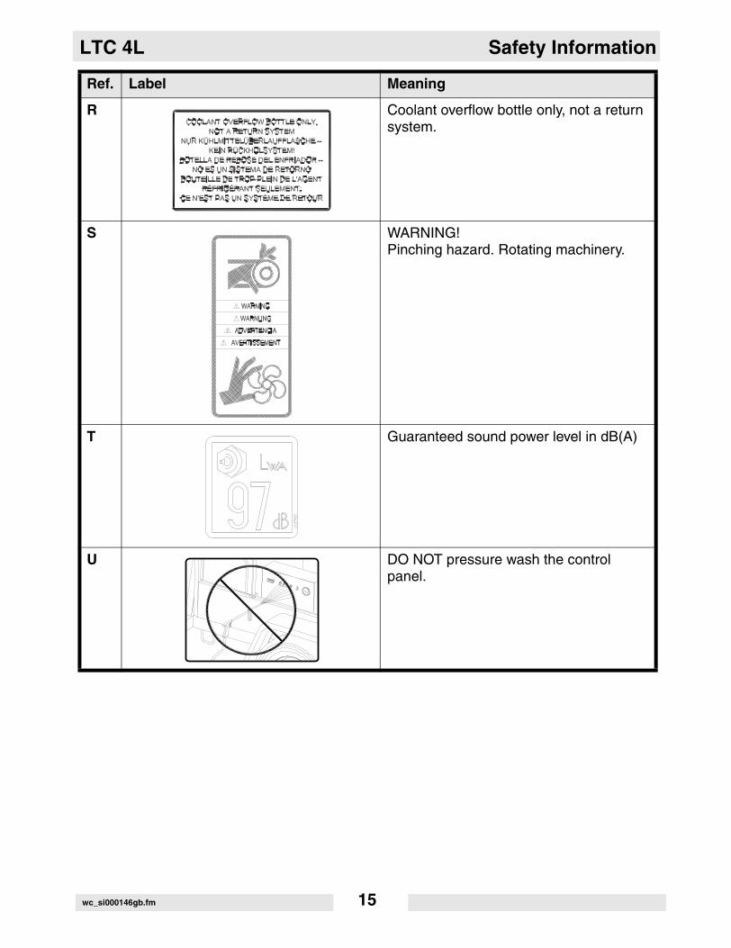
R Coolant overflow bottle only, not a return system.
S WARNING!Pinching hazard. Rotating machinery.
T Guaranteed sound power level in dB(A)
U DO NOT pressure wash the control panel.
Ref. Label Meaning
wc_si000146gb.fm 15

Technical Data LTC 4L
3. Technical Data
3.1 Engine
Item Number: LTC 4L - 115V0009379
LTC 4L - 230V 0009485
Engine
Make Lombardini
Model LDW1003
Type 3-cylinder, 4-cycle, liquid-cooled diesel
Maximum power rating kW (Hp) 8.5 (11.4)
Operating power rating kW (Hp) 7.6 (10.2)
Operating speed (no-load)
rpm 1500
Alternator V / A / W 12 / 45 / 540
Battery V/Ah/CCA 12 / 450
Air cleaner type dry-type element
Fuel type No. 2 diesel
Fuel tank capacity l (gal.) 114 (30)
Fuel consumption l (gal.) / hr. 1.71 (0.45)
Running time hours 67.7
Coolant capacity l (qts.) 4.7 (5.0)
Oil capacity l (qts.) 2.4 (2.5)
Oil weight SAE 15W40 CD or higher
wc_td000146gb.fm 16

LTC 4L Technical Data
3.2 Generator
3.3 Machine
Item Number: LTC 4L - 115V
0009379Rev. 104
and higher
LTC 4L - 115V
0009379Rev. 103and lower
LTC 4L - 230V
0009485Rev. 104
and higher
LTC 4L - 230V
0009485Rev. 103and lower
Generator
Frequency Hz 50 ± 2
Continuous output kW 6.0 5.0 6.0 5.0
Output volts 115 230
Amps A 43.5 21.7
Excitation type Capacitor / Brushless
Power factor 1.0
Voltage regulation - no load to full load
% ± 5.0
Speed rpm 1500
Item Number: LTC 4L - 115V0009379
LTC 4L - 230V 0009485
Machine
Height - mast extended m (ft.) 8.8 (29)
Lighting system (1000W)
4 metal halide light
Max. lighting coverage @ 0.5 ft. candles
m2 (ft2)acres
2824 (30,400)7
Sound level at 7 m(23 ft.)
dB(A)67
Sound pressure level at operator's location (LpA)
dB(A)91
Guaranteed sound power level (LWA)
dB(A)97
wc_td000146gb.fm 17

Operation LTC 4L
4. Operation
4.1 Adjusting Lights
See Graphic: wc_gr002090
Each light fixture can be aimed up, down, left or right. Position eachfixture by loosening toolless light adjusters (g) and aiming light up ordown. Do not loosen inside nut (x). Loosening this nut can damage thelight fixture. Loosen nut (h) to turn light fixtures left or right. Tightenadjusters and nuts after positioning lights.
Always return light fixtures to aim up or away from the ground whenmast is in the cradle for towing.
wc_tx000416gb.fm 18

LTC 4L Operation
4.2 Operating Lights
See Graphic: wc_gr002934
Turn on circuit breaker (a) first, then turn each circuit breaker (b) “ON”,one at a time.
Metal halide floodlights require a warm-up of 5–15 minutes before theyreach full output. If floodlights are shut down, a 10-minute cool-downperiod is required before turning them back on.
wc_tx000416gb.fm 19
Operation LTC 4L
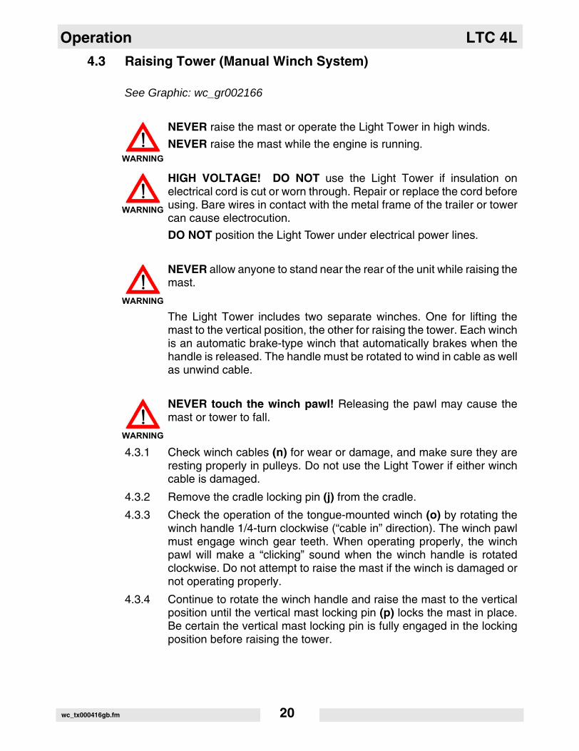
4.3 Raising Tower (Manual Winch System)
See Graphic: wc_gr002166
NEVER raise the mast or operate the Light Tower in high winds.
NEVER raise the mast while the engine is running.
HIGH VOLTAGE! DO NOT use the Light Tower if insulation onelectrical cord is cut or worn through. Repair or replace the cord beforeusing. Bare wires in contact with the metal frame of the trailer or towercan cause electrocution.
DO NOT position the Light Tower under electrical power lines.
NEVER allow anyone to stand near the rear of the unit while raising themast.
The Light Tower includes two separate winches. One for lifting themast to the vertical position, the other for raising the tower. Each winchis an automatic brake-type winch that automatically brakes when thehandle is released. The handle must be rotated to wind in cable as wellas unwind cable.
NEVER touch the winch pawl! Releasing the pawl may cause themast or tower to fall.
4.3.1 Check winch cables (n) for wear or damage, and make sure they areresting properly in pulleys. Do not use the Light Tower if either winchcable is damaged.
4.3.2 Remove the cradle locking pin (j) from the cradle.
4.3.3 Check the operation of the tongue-mounted winch (o) by rotating thewinch handle 1/4-turn clockwise (“cable in” direction). The winch pawlmust engage winch gear teeth. When operating properly, the winchpawl will make a “clicking” sound when the winch handle is rotatedclockwise. Do not attempt to raise the mast if the winch is damaged ornot operating properly.
4.3.4 Continue to rotate the winch handle and raise the mast to the verticalposition until the vertical mast locking pin (p) locks the mast in place.Be certain the vertical mast locking pin is fully engaged in the lockingposition before raising the tower.
WARNING
WARNING
WARNING
WARNING
wc_tx000416gb.fm 20

LTC 4L Operation
NEVER pull the vertical mast locking pin (p) while the tower israised! Releasing the vertical mast locking pin while the tower israised may cause the tower to fall or the machine to tip over.
4.3.5 After the mast is in the vertical position, check the operation of themast-mounted winch (q) by rotating the winch handle 1/4-turnclockwise (“cable in” direction). The winch pawl must engage winchgear teeth. When operating properly, it will make a “clicking” soundwhen the winch handle is rotated clockwise. Do not attempt to raise themast if the winch is damaged or not operating properly. Continuerotating the winch handle until mast is at the desired height. Do notover crank the winch when the tower is fully extended.
CAUTION: Do not extend the tower beyond the red marking on themast!
4.3.6 Once the tower is at the desired height, rotate the mast to the desireddirection. To rotate, loosen rotation locking knob (s). Then using thehandle (u), rotate the mast until the lights face the desired direction,and then retighten the rotation locking knob.
WARNING
wc_tx000416gb.fm 21

Operation LTC 4L
4.4 Lowering Tower (Manual Winch System)
See Graphic: wc_gr002166
Be sure to read and understand the operating instructions beforelowering the tower!
If for any reason a part of the mast hangs up or a winch cable developsslack before mast is fully lowered, stop immediately! Continuing toturn the winch handle will increase the slack in the cable. Too muchslack could cause the mast to collapse should it suddenly free up. If themast hangs up, level the trailer. Slightly shake or twist the towerassembly to free the bind. Contact an authorized WACKER servicerepresentative immediately.
NEVER lower the mast while the unit is operating.
NEVER allow anyone to stand near the rear of the unit while loweringthe mast.
4.4.1 Turn the lights off. Shut down the engine.
CAUTION: Shutting down the engine before turning off the lights coulddamage floodlight ballasts or generator capacitor(s).
CAUTION: Observe power cord while lowering the tower. Make surethe coiled cord is not damaged during the lowering process.
4.4.2 Lower the tower by turning the handle on the mast-mounted winch (q)counterclockwise (“cable out” direction).
NEVER touch the winch pawl! Releasing the winch pawl may causethe mast or tower to fall.
4.4.3 Loosen the rotation locking knob (s) and using the handle (u), rotatethe mast so the lights face the rear of the trailer and the mast-mountedwinch is facing toward the trailer tongue.
WARNING
WARNING
WARNING
WARNING
wc_tx000416gb.fm 22
LTC 4L Operation
4.4.4 Pull and hold the mast locking pin (p). Rotate the handle on the tongue-mounted winch (o) counterclockwise (“cable out” direction) until themast spring begins to pivot the mast down. Release the mast lockingpin and continue to rotate the handle until the mast is resting in thetransport cradle. Be sure that the secondary locking pin (t) penetratesall sections of the mast.
NEVER pull the vertical mast locking pin (e) while the tower israised! Releasing the locking pin while the tower is raised may causethe tower to fall or the machine to tip over.
4.4.5 After the mast is down, secure it in the cradle by inserting the cradlelock pin (j). Insert the clip through the pin to secure it in place.
4.4.6 Position the light fixtures to aim at the ground.
CAUTION: Allow the floodlights to cool 10–15 minutes before movingtrailer. Moving the trailer while the lights are still hot could cause thebulbs to break.
WARNING
wc_tx000416gb.fm 23

Operation LTC 4L
4.5 Control Panels - 50 Hz - Manual Winch System (0009379,0009485 Rev. 101 & lower)
Floodlight Control Panel Engine Control Panel
t
wc_gr002294
d
EMERGENCY
wc_tx000416gb.fm 24

LTC 4L Operation
Ref. Description Ref. Description
a 50 Amp circuit breaker l Alternator Indicator
b 15 Amp lights circuit breaker m Auxiliary lights (not used)
c 20 Amp GFI circuit breaker n Glow Plug Indicator
d Receptacle o Air Filter Restriction Indicator
e Hour Meter p Auxiliary lights (not used)
f Low Fuel Indicator (not used) q Key Access Door
g Safety Shutdown Indicator r 25 Amp Earth-leakage circuit breaker
h Low Oil Pressure Shutdown t Emergency stop switch
k High Coolant Temperature Shutdown
wc_tx000416gb.fm 25
Operation LTC 4L
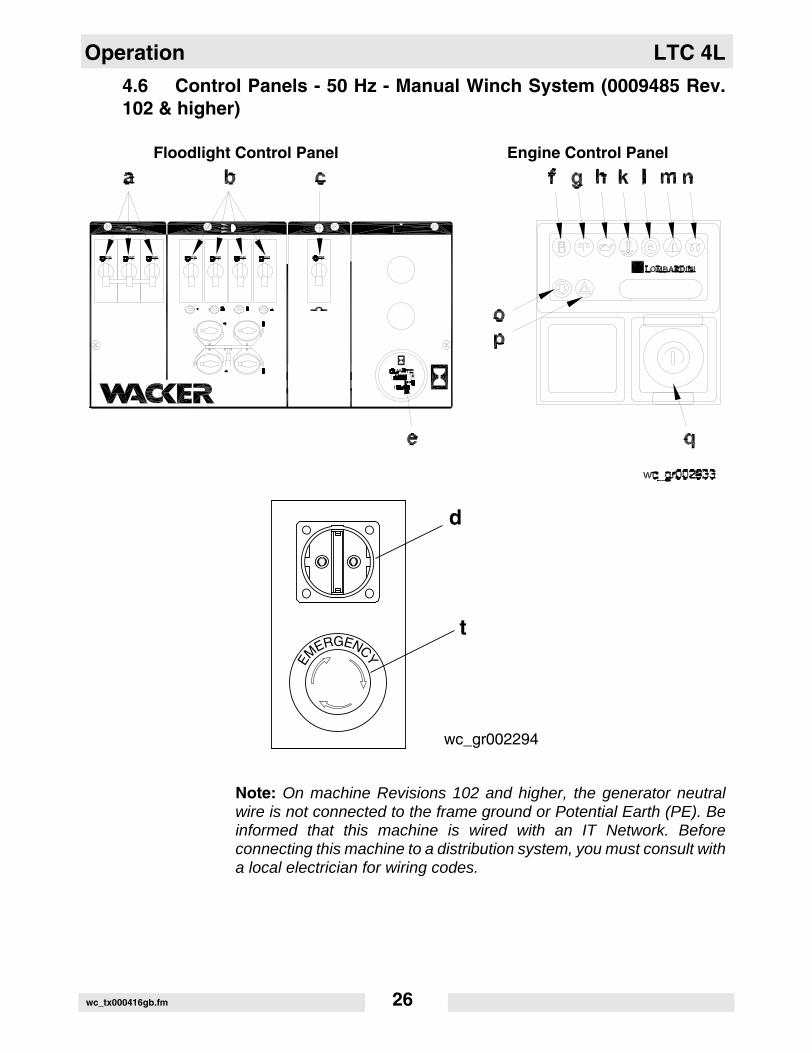
4.6 Control Panels - 50 Hz - Manual Winch System (0009485 Rev.102 & higher)
Floodlight Control Panel Engine Control Panel
Note: On machine Revisions 102 and higher, the generator neutralwire is not connected to the frame ground or Potential Earth (PE). Beinformed that this machine is wired with an IT Network. Beforeconnecting this machine to a distribution system, you must consult witha local electrician for wiring codes.
t
wc_gr002294
d
EMERGENCY
wc_tx000416gb.fm 26

LTC 4L Operation
Ref. Description Ref. Description
a 50 Amp circuit breaker k High Coolant Temperature Shutdown
b 15 Amp lights circuit breaker l Alternator Indicator
c 20 Amp GFI circuit breaker m Auxiliary lights (not used)
d Receptacle n Glow Plug Indicator
e Hour Meter o Air Filter Restriction Indicator
f Low Fuel Indicator (not used) p Auxiliary lights (not used)
g Safety Shutdown Indicator q Key Access Door
h Low Oil Pressure Shutdown t Emergency stop switch
wc_tx000416gb.fm 27

Operation LTC 4L
4.7 Starting
See Graphic: wc_gr002293, wc_gr0002294
4.7.1 Check engine oil, fuel and coolant levels.
Note: If fuel tank was drained or run dry it may be necessary to bleedfuel lines. Refer to Engine Operator’s Manual.
4.7.2 Check condition of electrical cable on mast. Do not start generator ifinsulation on cable is cut or worn through.
4.7.3 Check that the circuit breakers (a, b, c) are in their “OFF” position.
4.7.4 Check that the emergency stop switch (t) is pulled out.
CAUTION: Starting engine under load will damage the machine.
4.7.5 On machines equipped with the Lombardini engine, turn key (q) oneclick right. Glow plug indicator (n) will illuminate until engine is properlypreheated. This is an automatic timer based on engine temperature.Crank engine immediately after glow plug light goes off.
4.7.6 Turn key (q) to “START” and hold until engine starts. Release key afterengine starts.
CAUTION: Do not crank engine longer than 10 seconds. This couldcause starter motor to overheat. Return switch to “OFF” and wait 15-30 seconds for starter motor to cool down before attempting to preheatand restart.
Note: If oil pressure is not obtained within 30 seconds after key isturned to “RUN”, the automatic shutdown system will shut off the fuelsupply. You must return the key to the “OFF” position to restart the 30second timer before attempting to restart the engine.
4.7.7 Allow engine to warm up before operating floodlights.
CAUTION: Never use starting fluids to aid in starting of engine.
4.8 Automatic Shutdown
This unit is equipped with a low oil, high temperature auto-shutdownsystem. This system will automatically shut off the fuel supply to theengine if the oil pressure drops too low or the engine exceeds normaloperating temperatures. Return the key switch to “OFF” to reset theunit after an engine shutdown.
wc_tx000416gb.fm 28
LTC 4L Operation
4.9 Stopping
See Graphic: wc_gr002293
4.9.1 Turn the circuit breakers (a, b, c) off and remove any other loads fromthe generator.
CAUTION: Never shut down the engine without turning off the lights.Damage to the generator will occur.
4.9.2 Turn the key (q) to OFF.
4.10 Emergency Stop Switch
See Graphic: wc_gr002294
In case of emergency, push in the emergency stop switch (t) locatedon the front panel.
4.11 Derating
All generator sets are subject to derating for altitude and temperature.Although derating should not affect operation of the floodlights, it willreduce the available reserve power to the receptacle.
Ratings are typically reduced 3% per 300 m (1000 feet) elevation fromsea level, and 2% per 10°F (5.5°C) increase in ambient temperatureabove 78°F (25°C).
wc_tx000416gb.fm 29

Operation LTC 4L
4.12 Receptacle - 50 Hz
See Graphic: wc_gr002293, wc_gr002294
The machine is equipped with a convenience receptacle for runningaccessories and tools from the generator. Power to this receptacle isavailable any time the engine is running and the circuit breaker is “ON”.
CAUTION: With the lights on, do not draw more than 400 Watts fromthe 115V receptacle or 800 Watts from the 230V receptacle.
A circuit breaker (c) protects the receptacle (d).
CAUTION: Do not use frayed or damaged cords or plugs with auxiliaryoutlet.
CAUTION: Use only tough rubber-sheathed flexible cable orequivalent. (per 1EC245-4).
CAUTION: When using extension cords or mobile distributionnetworks the total length of cords for a cross section of 1.5 mm2 shouldnot exceed 60 m. For a cross section of 2.5 mm2, it should not exceed100 m.
Note: On machine Revisions 102 and higher, the generator neutralwire is not connected to the frame ground or Potential Earth (PE). Beinformed that this machine is wired with an IT Network. Beforeconnecting this machine to a distribution system, you must consult witha local electrician for wiring codes.
wc_tx000416gb.fm 30

LTC 4L Maintenance
5. Maintenance
5.1 Installing / Removing Light Fixtures
See Graphic: wc_gr002296
ALWAYS turn off light circuit breakers and shut down engine beforedisconnecting light fixtures or changing light bulbs.
Remove fixtures by disconnecting electrical cords using the quickdisconnects (a) or by disconnecting electrical cords at the junction box(b). Remove nuts (c) from fixture mounting brackets and remove bothfixture and bracket off stud.
CAUTION: Only a trained technician should be allowed to install andremove fixture wiring.
Note: When reinstalling the lamp fixtures, make sure the drain hole ispointing down.
Bulbs become extremely hot in use! Allow bulb and fixture to cool10-15 minutes before handling.
Numbering Sequence of Floodlights Junction Box Wiring for Floodlights
Wire Colors
B Black R Red Y Yellow Or Orange
G Green T Tan Br Brown Pr Purple
L Blue V Violet Cl Clear Sh Shield
P Pink W White Gr Gray LL Light blue
WARNING
WARNING
wc_tx000417gb.fm 31

Maintenance LTC 4L
5.2 Replacing / Removing Bulbs
The Light Tower uses four 1000W bulbs. When replacing or removingthe bulbs, avoid leaving any grease or oil residue on the glass surface.This can create hot spots, reducing the service life of the bulb orcausing the outer jacket to burst.
ALWAYS turn off the light circuit breakers and shut down the enginebefore disconnecting the light fixtures or changing the light bulbs.
Bulbs become extremely hot in use! Allow the bulb and fixture tocool 10–15 minutes before handling.
NEVER operate the lights without the protective lens cover inplace or with a lens cover that is cracked or damaged! The lampsused in the floodlights produce high temperatures and operate underpressure. They are subject to failures where the outer jacket burstsand shatters, resulting in a discharge of extremely hot glass particles.These particles pose a risk of personal injury, property damage, burnsand fire.
Ultraviolet radiation from the lamp can cause serious skin and eyeirritation. Use the lamp only with provided undamaged lens cover andfixture.
5.3 Daily Inspection
5.3.1 Check for fluid leaks. Check fluid levels.
5.3.2 Inspect condition of electrical cords. Do not use light tower if insulationis cut or worn through.
5.3.3 Check that winch cables are in good condition. Do not use a cable thatis kinked or starting to unravel.
5.3.4 Check that the vertical mast locking pin and its spring are secured,aligned, and operating properly.
WARNING
WARNING
WARNING
wc_tx000417gb.fm 32
LTC 4L Maintenance
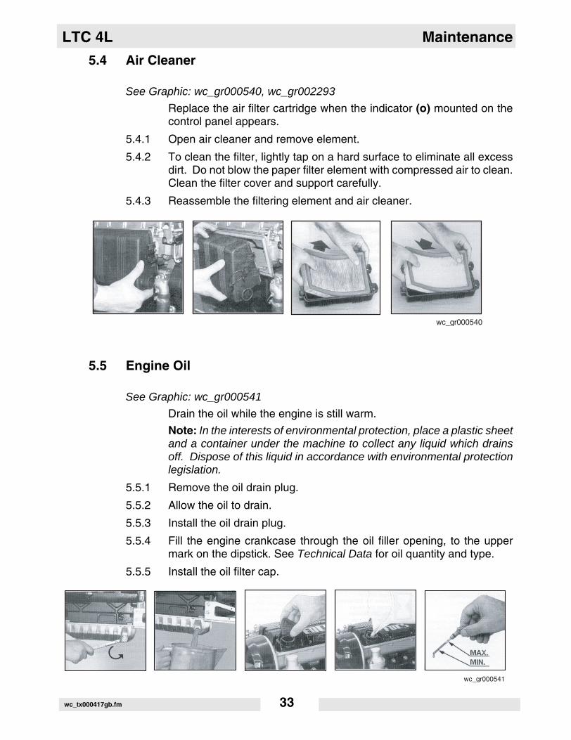
5.4 Air Cleaner
See Graphic: wc_gr000540, wc_gr002293
Replace the air filter cartridge when the indicator (o) mounted on thecontrol panel appears.
5.4.1 Open air cleaner and remove element.
5.4.2 To clean the filter, lightly tap on a hard surface to eliminate all excessdirt. Do not blow the paper filter element with compressed air to clean.Clean the filter cover and support carefully.
5.4.3 Reassemble the filtering element and air cleaner.
5.5 Engine Oil
See Graphic: wc_gr000541
Drain the oil while the engine is still warm.
Note: In the interests of environmental protection, place a plastic sheetand a container under the machine to collect any liquid which drainsoff. Dispose of this liquid in accordance with environmental protectionlegislation.
5.5.1 Remove the oil drain plug.
5.5.2 Allow the oil to drain.
5.5.3 Install the oil drain plug.
5.5.4 Fill the engine crankcase through the oil filler opening, to the uppermark on the dipstick. See Technical Data for oil quantity and type.
5.5.5 Install the oil filter cap.
wc_gr000540
wc_gr000541
wc_tx000417gb.fm 33

Maintenance LTC 4L
5.6 Engine Maintenance
Beforeeachuse
Every125
hours
Every250
hours
Every500
hours
Every1000 hours
or two years
Check for fluid leaks.
Check engine oil.
Check fuel level.
Replace air filter if indicator light is on.**
Change engine oil.*
Check level of battery electrolyte.
Check condition and tension on fan belt.
Check condition of radiator hoses.
Replace oil filter.*
Replace fuel filter.
Flush radiator.
Replace fan belt.
Check valve clearance.
Remove sediment in fuel tank.
Change radiator coolant.
Replace battery.
Replace radiator hoses and clamps.
Replace fuel pipes and clamps.
* Change engine oil and filter after first 50 hours of operation.** Replace air filter after air filter restriction switch indication or one year. Lombardini does not
recommend the removal of air filter elements for purposes of inspection.
wc_tx000417gb.fm 34

LTC 4L Maintenance
5.7 Troubleshooting
HIGH VOLTAGE! This unit uses high voltage circuits capable ofcausing serious injury or death. Only a qualified electrician shouldtroubleshoot or repair electrical problems occurring in this equipment.
Problem / Symptom Reason / Remedy
Lamp will not start • Lamp is too hot. Allow lamp to cool 10–15 minutes before restarting.
• Faulty lamp connection. Check that lamp is tight in socket. Check connections inside connection boxes on light fixtures and mast.
• Plug connection at fixture is loose or damaged.
• Lamp broken. Check for broken arc tube or outer lamp jacket, broken or loose components in lamp envelope, blackening or deposits inside lamp tube.
• Circuit breaker loose or defective.
• Generator output incorrect. Check incoming voltage to ballast. Incoming voltage should be 120V ± 5V. If voltage is incorrect, engine speed may need to be adjusted or generator may require service.
• Low or no ballast output. With the fixture cord removed from its receptacle, the voltage should measure 400 to 445 VAC. If proper voltage is not achieved, perform capacitor check to determine if capacitor or coil needs to be replaced.
Low Light Output • Lamp worn. Replace lamp due to normal lamp life.
• Low ballast output. Check ballast for proper voltage output.
• Fixture or lens dirty. Clean reflective surface inside fixture and both inside and outside surface of glass lens.
WARNING
wc_tx000417gb.fm 35
Maintenance LTC 4L
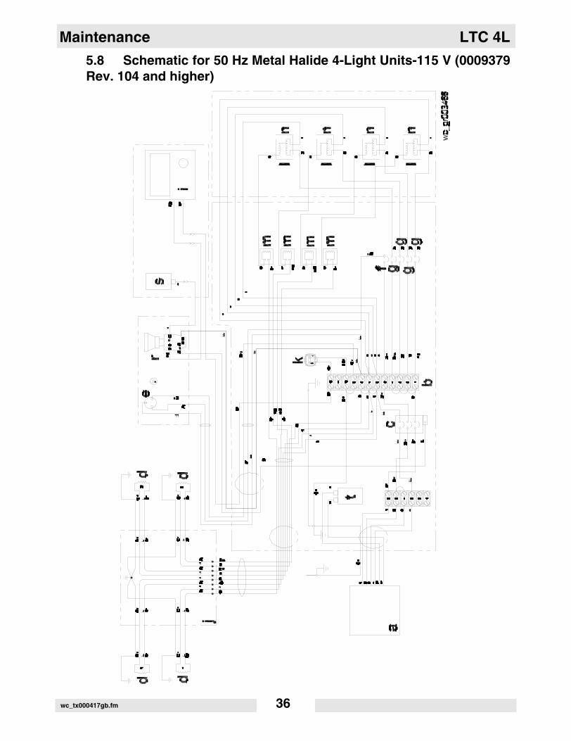
5.8 Schematic for 50 Hz Metal Halide 4-Light Units-115 V (0009379Rev. 104 and higher)
wc_tx000417gb.fm 36

LTC 4L Maintenance
Note: On machine Revisions 102 and higher, the generator neutralwire is not connected to the frame ground or Potential Earth (PE). Beinformed that this machine is wired with an IT Network. Beforeconnecting this machine to a distribution system, you must consult witha local electrician for wiring codes.
Ref. Description Ref. Description
a Generator j Junction box
b Terminal strip k Hour meter
c Main circuit breaker, 25 Amp l Transformer
d Floodlight receptacles m Capacitor, 525V
e Receptacle, 115V n Ballasts
f Circuit breaker, 20 Amp r Emergency stop switch
g Circuit breaker, 15 Amp s Solenoid
i Engine control panel t Capacitor, 450V
Wire Colors
B Black R Red Y Yellow Or Orange
G Green T Tan Br Brown Pr Purple
L Blue V Violet Cl Clear Sh Shield
P Pink W White Gr Gray LL Light blue
wc_tx000417gb.fm 37

Maintenance LTC 4L
5.9 Schematic for 50 Hz Metal Halide 4-Light Units-115 V (0009379Rev. 102 and 103)
P1 P2 P3
B+ W
D+Or
t
Y/B
Gr
Or/B
Y/B
Gr
Or/B
Y/B
Gr
Or/B
Y/B
Gr
Or/B
wc_gr003237
wc_tx000417gb.fm 38

LTC 4L Maintenance
Note: On machine Revisions 102 and higher, the generator neutralwire is not connected to the frame ground or Potential Earth (PE). Beinformed that this machine is wired with an IT Network. Beforeconnecting this machine to a distribution system, you must consult witha local electrician for wiring codes.
Ref. Description Ref. Description
a Generator j Junction box
b Terminal strip k Hour meter
c Main circuit breaker l Transformer
d Floodlight receptacles m Capacitor
e Receptacle, 115V n Coil cord
f Circuit breaker, 20 Amp r Emergency stop switch
g Circuit breaker, 15 Amp s Fuel solenoid
i Engine control panel t Alternator
Wire Colors
B Black R Red Y Yellow Or Orange
G Green T Tan Br Brown Pr Purple
L Blue V Violet Cl Clear Sh Shield
P Pink W White Gr Gray LL Light blue
wc_tx000417gb.fm 39

Maintenance LTC 4L
5.10 Schematic for 50 Hz Metal Halide 4-Light Units-115 V (0009379Rev. 101 and lower)
P3 P2 P1
B+ W
D+OrOr
t
Y/B
Gr
Or/B
Y/B
Gr
Or/B
Y/B
Gr
Or/B
Y/B
Gr
Or/B
wc_tx000417gb.fm 40

LTC 4L Maintenance
Ref. Description Ref. Description
a Generator j Junction box
b Terminal strip k Hour meter
c Main circuit breaker l Transformer
d Floodlight receptacles m Capacitor
e Receptacle, 115V n Coil cord
f Circuit breaker, 20 Amp p Earth-leakage circuit breaker, 25 Amp
g Circuit breaker, 15 Amp r Emergency stop switch
h Quick disconnect plugs s Fuel solenoid
i Engine control panel t Alternator
Wire Colors
B Black R Red Y Yellow Or Orange
G Green T Tan Br Brown Pr Purple
L Blue V Violet Cl Clear Sh Shield
P Pink W White Gr Gray LL Light blue
wc_tx000417gb.fm 41

Maintenance LTC 4L
5.11 Schematic for 50 Hz Metal Halide 4-Light Units-230 V (0009485Rev. 104 and higher)
wc_tx000417gb.fm 42

LTC 4L Maintenance
Note: On machine Revisions 102 and higher, the generator neutralwire is not connected to the frame ground or Potential Earth (PE). Beinformed that this machine is wired with an IT Network. Beforeconnecting this machine to a distribution system, you must consult witha local electrician for wiring codes.
Ref. Description Ref. Description
a Generator j Junction box
b Terminal strip k Hour meter
c Main circuit breaker, 25 Amp l Transformer
d Floodlight receptacles m Capacitor, 525V
e Receptacle, 115V n Ballasts
f Circuit breaker, 20 Amp r Emergency stop switch
g Circuit breaker, 15 Amp s Solenoid
i Engine control panel t Capacitor, 450V
Wire Colors
B Black R Red Y Yellow Or Orange
G Green T Tan Br Brown Pr Purple
L Blue V Violet Cl Clear Sh Shield
P Pink W White Gr Gray LL Light blue
wc_tx000417gb.fm 43

Maintenance LTC 4L
5.12 Schematic for 50 Hz Metal Halide 4-Light Units-230 V (0009485Rev. 102 and103)
P3 P2 P1
B+ W
D+OrOr
t
12
Y/B
Gr
Or/B
Y/B
Gr
Or/B
Y/B
Gr
Or/B
Y/B
Gr
Or/B
wc_tx000417gb.fm 44

LTC 4L Maintenance
Note: On machine Revisions 102 and higher, the generator neutralwire is not connected to the frame ground or Potential Earth (PE). Beinformed that this machine is wired with an IT Network. Beforeconnecting this machine to a distribution system, you must consult witha local electrician for wiring codes.
Ref. Description Ref. Description
a Generator i Auxiliary connection of engine con-trol panel
b Terminal strip j Junction box
c Main circuit breaker k Hour meter
d Floodlight receptacles l Transformer
e 230 V Receptacle m Capacitor
f 20 Amp circuit breaker n Coil cord
g 15 Amp circuit breaker r Emergency stop switch
h Quick disconnect plugs s Fuel solenoid
Wire Colors
B Black R Red Y Yellow Or Orange
G Green T Tan Br Brown Pr Purple
L Blue V Violet Cl Clear Sh Shield
P Pink W White Gr Gray LL Light blue
wc_tx000417gb.fm 45

Maintenance LTC 4L
5.13 Schematic for 50 Hz Metal Halide 4-Light Units-230 V (0009485Rev. 101 and lower)
P3 P2 P1
Y/B
Gr
Or/B
Y/B
Gr
Or/B
Y/B
Gr
Or/B
Y/B
Gr
Or/B
B+W
D+OrOr
t
wc_tx000417gb.fm 46

LTC 4L Maintenance
Ref. Description Ref. Description
a Generator j Junction box
b Terminal strip k Hour meter
c Main circuit breaker l Transformer
d Floodlight receptacles m Capacitor
e Receptacle, 230V n Coil cord
f Circuit breaker, 20 Amp p Earth-leakage circuit breaker, 25 Amp
g Circuit breaker, 15 Amp r Emergency stop switch
h Quick disconnect plugs s Fuel solenoid
i Engine control panel t Alternator
Wire Colors
B Black R Red Y Yellow Or Orange
G Green T Tan Br Brown Pr Purple
L Blue V Violet Cl Clear Sh Shield
P Pink W White Gr Gray LL Light blue
wc_tx000417gb.fm 47

Maintenance LTC 4L
5.14 Generator Capacitor Excitation Schematic 50 Hz
Ref. Description Ref. Description
1 Rotor 4 Capacitor
2 Stator 5 Generator/Terminal block
3 Excitation coils 6 Control box-Main circuit breaker
P3
P2
P1
wc_tx000417gb.fm 48

LTC 4L Maintenance
5.15 Engine Wiring - Lombardini
Ref. Description Ref. Description
1 Fuel Solenoid 7 Air Filter Restriction Indicator (normal open type)
2 Glow Plugs 8 Low Fuel Level Switch (not used, nor-mal open type)
3 Starter Motor 9 Low Oil Pressure Switch (normal closed type)
4 Battery 10 Coolant High Temperature Switch (normal open type)
5 Alternator Connector 11 Coolant Temperature Thermistor (for preheat relay)
6 Coolant Temperature Sending Unit (not used, for remote temperature gauge or LED)
wc_tx000417gb.fm 49
Maintenance LTC 4L
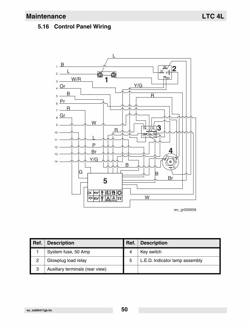
5.16 Control Panel Wiring
Ref. Description Ref. Description
1 System fuse, 50 Amp 4 Key switch
2 Glowplug load relay 5 L.E.D. Indicator lamp assembly
3 Auxiliary terminals (rear view)
L
BL
W/ROr
B
PrR
Gr
W
L
PBr
Y/G
GB
W
BBr
Y/G
R
R
86
85
30 87
4 27 6 5
12 10 9
50
30
15 / 54
wc_gr000658
1
2
5
3
4
1
2
3
4
5
6
7
8
9
10
11
12
13
14
wc_tx000417gb.fm 50

2006-CE-LTC4L_Q.fm
William Lahner Dan DomanskiVice President of Engineering Manager, Product Engineering
WACKER CORPORATIONDate / Datum / Fecha / Date
EC DECLARATION OF CONFORMITYCE-KONFORMITÄTSERKLÄRUNG
DECLARACIÓN DE CONFORMIDAD DE LA CE DÉCLARATION DE CONFORMITÉ C.E.
WACKER CORPORATION, N92 W15000 ANTHONY AVENUE, MENOMONEE FALLS, WISCONSIN USA
hereby certifies that the construction equipment specified hereunder / bescheinigt, daß das Baugerät / certifica que la máquina de construcción / atteste que le matériel :
1. Category / Art / Categoría / Catégorie
Power Generators (Light Towers)Kraftstromerzeuger (Beleuchtungsanlagen)
Grupos Electrógenos (Torres de Iluminación)Groupe Électrogènes de Puissance (Tours d’éclairage)
2. Type - Typ - Tipo - Type LTC 4L
3. Item number of equipment / Artikelnummer / Número de referencia de la máquina / Numéro de référence du matériel :
0009379, 0009485
4. Electric power / Elektrische Leistung / Potencia eléctrica / Force motrice :
6,0 kW
Has been sound tested per Directive 2000/14/EC / In Übereinstimmung mit Richtlinie 2000/14/EG bewertet worden ist / Ha sido ensayado en conformidad con la norma 2000/14/CE / A été mis à l’épreuve conforme aux dispositions de la directive 2000/14/CEE :
and has been produced in accordance with the following standards:und in Übereinstimmung mit folgenden Richtlinien hergestellt worden ist:y ha sido fabricado en conformidad con las siguientes normas:et a été produit conforme aux dispositions des directives européennes ci-après :
2000/14/EC89/336/EEC98/37/EEC
AUTHORIZED REPRESENTATIVE IN THE EUROPEAN UNIONBEVOLLMÄCHTIGTER VERTRETER FÜR DIE EUROPÄISCHE GEMEINSCHAFTREPRESENTANTE AUTORIZADO EN LA UNIÓN EUROPEAREPRÉSENTANT AGRÉÉ AUPRÈS DE L’UNION EUROPÉENNE
WACKER CONSTRUCTION EQUIPMENT AGPreußenstraße 4180809 München
Conformity Assessment Procedure / Konformitätsbewertungsverfahren / Procedimiento para ensayar conformidad / Procédé pour l’épreuve de conformité
Name and address of notified body / Bei folgender einbezogener Prüfstelle / Oficina matriculadora / Organisme agrée
Measured sound power level / Gemessener Schallleistungspegel / Nivel de potencia acústica determinado / Niveau de puissance acoustique fixé
Guaranteed sound power level / Garantierter Schallleistungspegel / Nivel de potencia acústica garantizado / Niveau de puissance acoustique garanti
Annex VI / Anhang VIAnexo VI / Annexe VI
TUV Süddeutschland Bau und Betrieb GmbH
(0036) Westendstr. 199
D-80686 Munchen
91 dB(A) 97 dB(A)
10.04.06

Wacker Construction Equipment AG · Preußenstraße 41 · D-80809 München · Tel.: +49-(0)89-3 54 02 - 0 · Fax: +49 - (0)89-3 54 02-3 90Wacker Corporation · P.O. Box 9007 · Menomonee Falls, WI 53052-9007 · Tel. : (262) 255-0500 · Fax: (262) 255-0550 · Tel. : (800) 770-0957Wacker Asia Pacific Operations · Skyline Tower, Suite 2303, 23/F · 39 Wang Kwong Road, Kowloon Bay, Hong Kong · Tel. +852 2406 60 32 · Fax: +852 2406 60 21