wavelets and counterlets
TRANSCRIPT

Pattern Recognition usingWavelets &Contourlets
PROJECT Group No - 24

MOTIVATION
Wavelet transform & Contourlet transform are relatively new theories, they have enjoyed a tremendous attention and success over the last decade.
Almost all signals encountred in practice call for a time-frequency analysis, and wavelets provide a very simple and efficient way to perform such an analysis. While Contourlet tranform is a new two dimensional transform method for image representation.
Still, there’s a lot to discover in these new theories, due to the infinite variety of non-stationary signals encountred in real life.

Overview Introduction About Fourier Transform Short-Time Fourier Transform Principle of Wavelet & Contourlet Transform Applications Time-Frame Distribution Conclusion References

INTRODUCTIONOur main concern is to get the information from frequency domain which is not available in Time Domain representation. There are different transform available for getting information from frequency domain :• FOURIER TRANSFORM• SHORT TIME FOURIER TRANSFORM• WAVELET TRANSFORM, etc.
Why do we need the frequency information ?Often times, the information that cannot be readily seen in the time-domain can be seen in the frequency domain.
So how do we measure the frequency content of a signal FOURIER TRANSFORM (FT)
Fourier transform are applied to signals to obtain a further information from the signal that is not readily available in the Time domain signal (raw signal).Moreover, If the FT of a signal in time domain is taken, the frequency-amplitude representation of that signal is obtained.

NOTHING MORE, NOTHING LESS ... Fourier Transform is a reversible transform, that is, it allows to go back and
forward between the raw and processed (transformed) signals. However, only either of them is available at any given time.
No frequency information is available in the time-domain signal, and no time information is available in the Fourier transformed signal.
FT gives the frequency information of the signal, which means that it tells us how much of each frequency exists in the signal, but it does not tell us when in time these frequency components exist.
STATIONARY AND NON-STATIONARY SIGNALS
FT identifies all spectral components present in the signal, however it does not provide any information regarding the temporal (time) localization of these components. Why?
Most of Transportation Signals are Non-stationary. (We need to know whether and also when an incident was happened.)

Stationary signals consist of spectral components that do not change in time all spectral components exist at all times no need to know any time information FT works well for stationary signals
However,Non-stationary signals consists of time varying spectral components How do we find out which spectral component appears when? FT only provides what spectral components exist , not where in time they are
located. Need some other ways to determine time localization of spectral components)52cos()(1 ttx )252cos()(2 ttx )502cos()(3 ttx
)502cos()252cos(
)52cos()(4
ttttx
][)( 3215 xxxtx
Concatenation

X4(ω)
X5(ω)Perfect knowledge of what frequencies exist, but no information about where these frequencies are located in time

So We Need a local analysis scheme for a time-frequency representation of
non stationary signals
THE SHORT TIME FOURIER TRANSFORM Dennis Gabor (1946) Used STFT to analyze only a small section of the signal at a time by a technique called Windowing the Signal. The Segment of Signal is Assumed Stationary.
Steps Involved in STFT :1. Choose a window function of finite length2. Place the window on top of the signal at t=03. Truncate the signal using this window4. Compute the FT of the truncated signal5. Incrementally slide the window to the right
6. Go to step 3, until window reaches the end of the signal. For each time location where the window is centered, we obtain a different FT
Hence, each FT provides the spectral information of a separate time-slice of the signal, providing simultaneous time and frequency information.
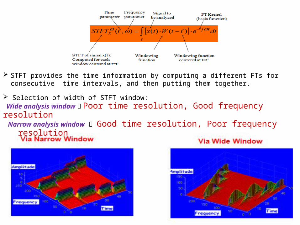
STFT provides the time information by computing a different FTs for consecutive time intervals, and then putting them together.
Selection of width of STFT window: Wide analysis window Poor time resolution, Good frequency resolution Narrow analysis window Good time resolution, Poor frequency
resolution

DRAWBACKS OF STFT Unchanged Window Dilemma of Resolution
Narrow window -> poor frequency resolution Wide window -> poor time resolution
Heisenberg Uncertainty Principle Cannot know what frequency exists at what time intervals.
Heisenberg Principle41
ft
Time resolution: How well two spikes in time can be separated from each other in the transform domain
Frequency resolution: How well two spectral components can be separated from each other in the transform domain
Both time and frequency resolutions cannot be arbitrarily high!!!We cannot precisely know at what time instance a frequency component is
located. We can only know what interval of frequencies are present in which time intervals.

WAVELET TRANSFORMWavelet A Wavelet is a wave-like oscillation with an amplitude that begins at zero, increases and decreases back to zero.
Wavelet Transform Wavelet Transformation is basically a mathematical technique in which a particular signal is analyzed in the time domain by using different versions of a translated and dilated basis function called the Wavelet Prototype or mother wavelet.
It overcomes the preset resolution problem of the STFT by using a variable length window
Analysis windows of different lengths are used for different frequencies: Analysis of high frequencies Use narrower windows for better time
resolution Analysis of low frequencies Use wider windows for better frequency
resolution
This works well, if the signal to be analyzed mainly consists of slowly varying characteristics with occasional short high frequency bursts.
Heisenberg principle still holds!!!The function used to window the signal is called THE WAVELET.
There are two type of wavelet Transform: 1) Continuous wavelet transform 2) Discrete wavelet transform

CONTINUOUS WAVELET TRANSFORMThe continuous transform is mainly done by using Fourier Transformation which uses sine and cosine as basis functions for analyzing a signal. Because wavelet are generally infinites as well as periodic in nature , so Fourier Transform is appropriate.
txx dt
sttx
sssCWT 1),(),(
Continuous wavelet transform of the signal x(t) using the analysis wavelet (.)
Translation parameter, measure of time
Scale parameter, measure of frequency
The mother wavelet. All kernels are obtained by translating (shifting) and/or scaling the mother wavelet
A normaliz
ation constant Signal to
be analyzed
Scale = 1/frequency
Discrete Wavelet TransformDiscrete Wavelet transform are generally used for digital images when they need to be viewed or processed at multiple resolutions.

Time-frequency resolution
Time
Frequency
Better time resolution;Poor frequency resolution
Better frequency resolution;Poor time resolution
• Each box represents a equal portion • Resolution in STFT is selected once for entire analysis

Contourlet Transform
The Contourlet transform which was proposed by Do and Vetterli in 2002, is a new two-dimensional transform method for image representations
Basic functions are multiscale & multidimensional
Captures smooth contours and edges at any orientation
Derived directly from discrete domain instead of extending from continuous domain
It consists of two filter bank stages, first is used to capture the point discontinuities, which is then followed by a directional filter bank (DFB) to link point discontinuities into linear structures
Application : Graphic equalizer, Filters noise, etc.

APPLICATION Audio compression
Speech recognition
Image and video compression
Denoising Signals

Time Frame Distribution
1st Semester MSE:- Literature Survey and Theoretical ComparisonESE:- (a). Problem Analysis (b). Mathematical Formulation
2nd Semester(a). Simulation and Verification(b). Comparison of Simulation result

CONCLUSION
FT works with Stationary signal. While STFT work with both stationary as well as non-stationary
signal, but having resolution problem. So to overcome this resolution problem we switched to Wavelet
transform using variable window size, but limited to 1-D transform.
Further for two-dimensional representation of image we proceed to Contourlet transform.

References
Robi Polikar, The Wavelet Tutorial, http://users.rowan.edu/~polikar/WAVELETS/WTpart1html http://users.rowan.edu/~polikar/WAVELETS/WTpart2html http://users.rowan.edu/~polikar/WAVELETS/WTpart3html
http://www.jitbm.com/12th%20volume/meaad%207.pdf
The Contourlet Transform: An Efficient Directional Multiresolution Image Representation
http://minhdo.ece.illinois.edu/publications/contourlet_txform.pdf
Signals & Systems ~ By Ramesh Babu
