waveform acquisition basics...sep 22, 2017 · the introduction of “fake” frequency content at...
TRANSCRIPT
© 2017 Rensselaer Polytechnic Institute. All rights reserved.
Waveform Acquisition Basics
Andrew Bierman, MSLighting Research Center, Rensselaer Polytechnic Institute
ENERGY STAR® Flicker Testing TutorialSeptember 22, 2017
© 2017 Rensselaer Polytechnic Institute. All rights reserved.
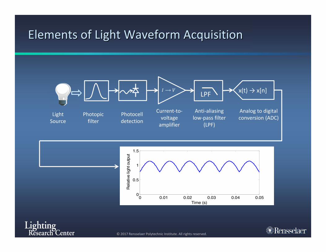
Elements of Light Waveform Acquisition
LPF x(t) → x[n]
Analog to digital conversion (ADC)
Anti-aliasing low-pass filter
(LPF)
Current-to-voltage
amplifier
Photocell detection
Photopic filter
Light Source
⟶
0 0.01 0.02 0.03 0.04 0.050
0.5
1
1.5
Time (s)
Rel
ativ
e lig
ht o
utpu
t
© 2017 Rensselaer Polytechnic Institute. All rights reserved.
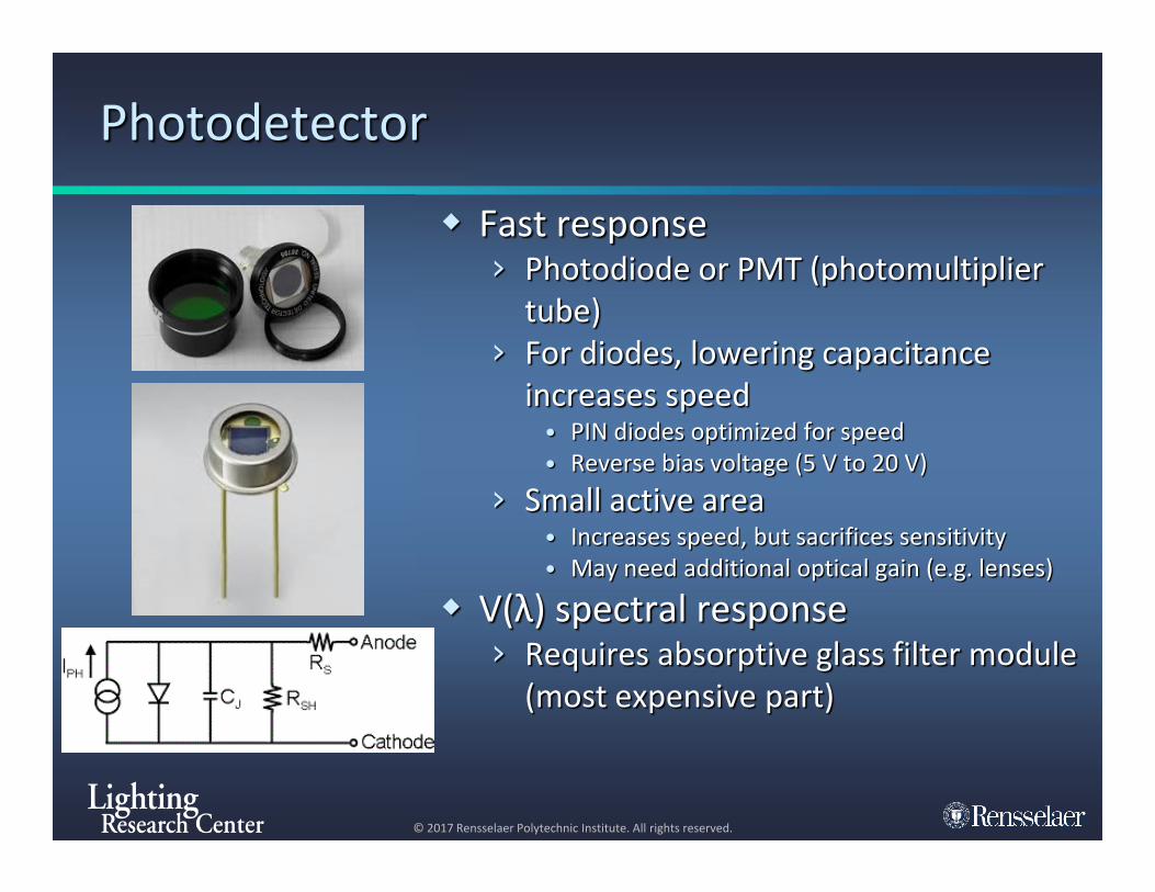
Photodetector
Fast response› Photodiode or PMT (photomultiplier
tube)› For diodes, lowering capacitance
increases speed• PIN diodes optimized for speed• Reverse bias voltage (5 V to 20 V)
› Small active area• Increases speed, but sacrifices sensitivity• May need additional optical gain (e.g. lenses)
V(λ) spectral response› Requires absorptive glass filter module
(most expensive part)

© 2017 Rensselaer Polytechnic Institute. All rights reserved.
Amplifier: Using passive probe
Gain = (9M + 1M) = 107 V/A Maximum Vin ≈ 0.2 volts or less;
not very linear Speed limited by diode
capacitance
Gai
n [V
/A]
C = 100 pF
Source: Horowitz and Hill, The Art of Electronics, 3rd
Edition, Cambridge Univ. Press, New York 2015

© 2017 Rensselaer Polytechnic Institute. All rights reserved.
Transimpedance Amplifier
Advantages Op-amp maintains linearity of
photodiode (virtual short-circuit current)
Feedback produces flat gain up to frequency cut-off› kHz to MHz depending on Op-
amp and Rf
Provides low impedance voltage output for anti-aliasing filter and ADC
Op-amp
© 2017 Rensselaer Polytechnic Institute. All rights reserved.
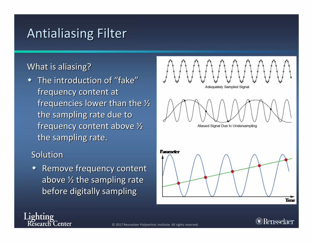
Antialiasing Filter
What is aliasing? The introduction of “fake”
frequency content at frequencies lower than the ½ the sampling rate due to frequency content above ½ the sampling rate.
Solution Remove frequency content
above ½ the sampling rate before digitally sampling

© 2017 Rensselaer Polytechnic Institute. All rights reserved.
Antialiasing Filter Examples
Filter for measuring direct flicker
4th order Bessel Low Pass Filter Frequencies of interest› f < 100 Hz
For sampling rate > 5 kHz
Oversampling Simple RC filters can be used if
sample rate is very high, fS > 100 kHz
• Some filter types can cause phase distortions, ripples and overshoot
Gai
n [V
/V]
Gai
n [V
/V]

© 2017 Rensselaer Polytechnic Institute. All rights reserved.
Analog Front-end
Transimpedance Amplifier Anti-aliasing Filter
© 2017 Rensselaer Polytechnic Institute. All rights reserved.
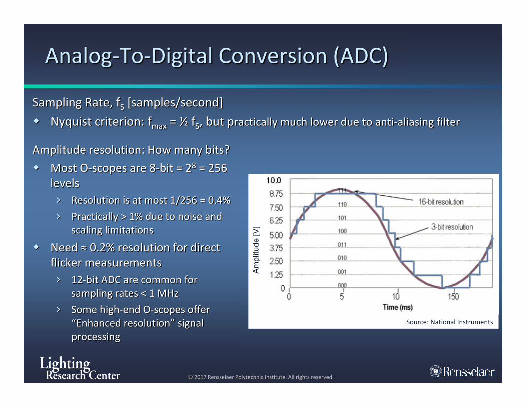
Analog-To-Digital Conversion (ADC)
Sampling Rate, fS [samples/second] Nyquist criterion: fmax = ½ fS, but practically much lower due to anti-aliasing filter
Amplitude resolution: How many bits? Most O-scopes are 8-bit = 28 = 256
levels› Resolution is at most 1/256 = 0.4%› Practically > 1% due to noise and
scaling limitations Need ≈ 0.2% resolution for direct
flicker measurements› 12-bit ADC are common for
sampling rates < 1 MHz› Some high-end O-scopes offer
“Enhanced resolution” signal processing
Am
plitu
de [V
]
Source: National Instruments
© 2017 Rensselaer Polytechnic Institute. All rights reserved.
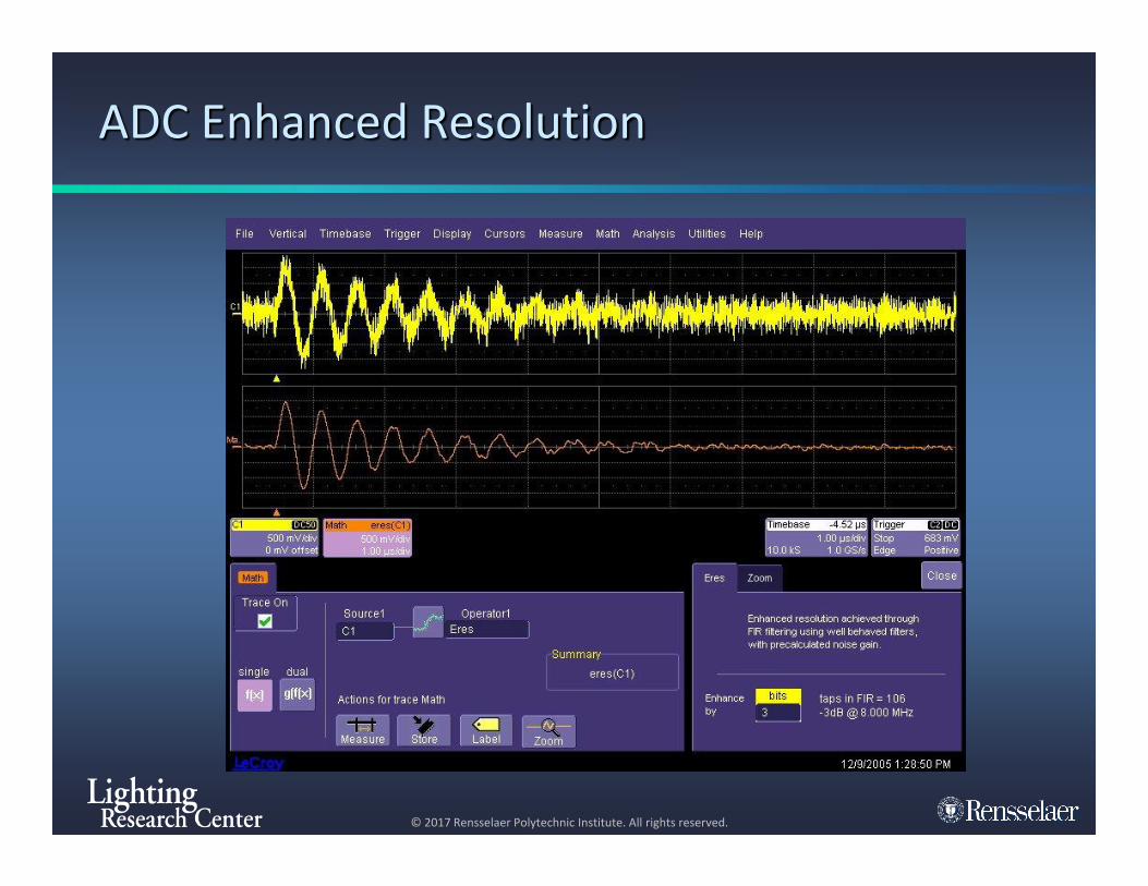
ADC Enhanced Resolution
© 2017 Rensselaer Polytechnic Institute. All rights reserved.
Thank you!
Acknowledgments› ASSIST program sponsors› US Environmental Protection Agency› LRC faculty, staff and students
Questions?http://www.lrc.rpi.edu/programs/solidstate/assist/recommends/flicker.asp
11