wave work group communications wave ... - motorola solutions · pdf filecommunication can be...
TRANSCRIPT
WHITE PAPER WAVE WORK GROUP COMMUNICATIONS
WAVE WORK GROUP COMMUNICATIONS
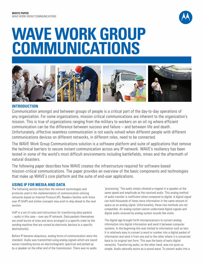
INTRODUCTION Communication amongst and between groups of people is a critical part of the day-to-day operations of any organization. For some organizations, mission critical communications are inherent to the organization’s mission. This is true of organizations ranging from the military to workers on an oil rig where efficient communication can be the difference between success and failure – and between life and death. Unfortunately, effective seamless communication is not easily solved when different people with different communications devices on different networks, in different roles, need to be connected.
The WAVE Work Group Communications solution is a software platform and suite of applications that remove the technical barriers to secure instant communication across any IP network. WAVE’s resiliency has been tested in some of the world’s most difficult environments including battlefields, mines and the aftermath of natural disasters.
The following paper describes how WAVE creates the infrastructure required for software-based mission-critical communications. The paper provides an overview of the basic components and technologies that make up WAVE’s core platform and the suite of end-user applications.
USING IP FOR MEDIA AND DATA The following section describes the network technologies and protocols used in the implementation of communication utilizing networks based on Internet Protocol (IP). Readers familiar with Voice over IP (VoIP) and similar concepts may wish to skip ahead to the next section.
VoIP is a set of rules and instructions for transferring data packets – audio in this case – over any IP network. Data packets themselves are small bursts of ones and zeros arranged in a specific order by the sending machine that are routed by electronic devices to a specific destination(s).
Before IP became ubiquitous, analog forms of communication were the standard. Audio was transmitted using analog signals which are sound waves travelling across an electromagnetic spectrum and picked up by a speaker on the other end of the transmission. There was no audio
‘processing.’ The audio simply vibrated a magnet in a speaker at the same speed and amplitude as the received audio. This analog method of audio transfer is inefficient when compared to digital. A digital signal can hold thousands of times more information in the same amount of space as an analog signal. Unfortunately, these two methods are not compatible. An analog system cannot understand digital signals and digital audio received by analog system sounds like static.
The digital age brought forth microprocessors to convert analog information into digital information and send it between computer systems. In the beginning this was limited to information such as text. It is relatively easy to convert a word or number into a digital packet of information and send it from one end to the other where it is converted back to its original text form. This was the basis of early digital networks. Transferring audio, on the other hand, was not quite so simple. Audio naturally exists as a sound wave. To convert audio into a
WHITE PAPER WAVE WORK GROUP COMMUNICATIONS
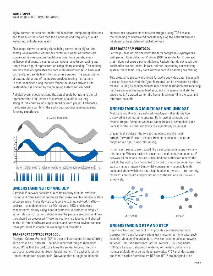
ANALOG TO DIGITAL
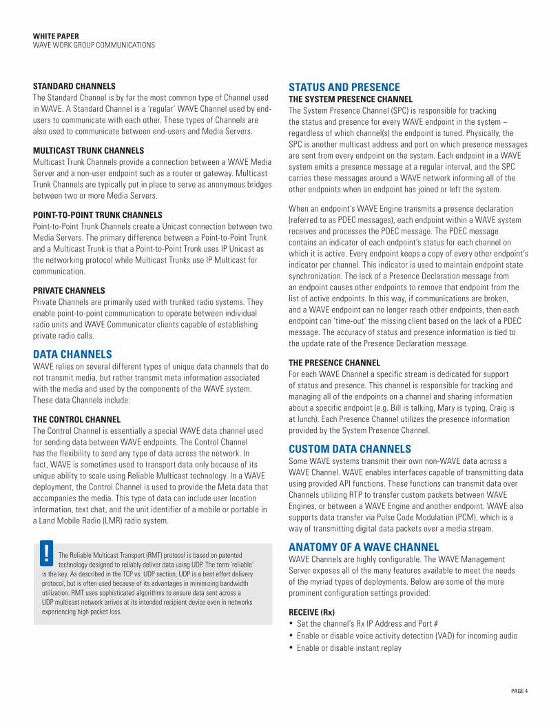
UNICASTMULTICAST
digital format that can be transferred in packets, computer applications had to be built that could map the amplitude and frequency of audio waves into a digital equivalent.
This image shows an analog signal being converted to digital. An analog wave (which is essentially continuous as far as humans are concerned) is measured as height over time. For example, every millisecond of sound, a computer can take an amplitude reading and turn it into a digital representation using binary encoding. The sending machine then encapsulates the data with instructions (also binary) at both ends, and sends that information as a packet. The encapsulation of data at either end of the packet provides routing instructions to other machines along the way. When the packet arrives at its destination it is opened by the receiving system and decoded.
A digital system does not send the actual audio but rather a digital representation of it. Instead of a stream of audio it is a long string of individual sounds represented by each packet. Fortunately, the human brain can fill in the audio gaps producing an equivalent listening experience.
UNDERSTANDING TCP AND UDP A typical IP network consists of a complex array of hubs, switches, routers and other network hardware that make possible communication between users. These devices collaborate to bring network traffic—packets—to endpoints such as PCs, servers, PBXs and devices connected wirelessly using a set of protocols. A protocol is simply a set of rules or instructions about where the packets are going and how they should be processed. These instructions are labeled and obeyed so that different software applications and hardware devices can use those protocols to enable the exchange of information.
TRANSPORT CONTROL PROTOCOL Transport Control Protocol (TCP) is a set of instructions for transferring data across an IP network. The most important thing to remember about TCP is that the protocol allows the sender to be notified if a particular packet does not reach its destination. If a packet is lost in transit, the packet is sent again. Networks that struggle to maintain
connections between machines can struggle using TCP because the resending of undelivered packets may clog the network thereby heightening the problem of packet delivery.
USER DATAGRAM PROTOCOL For the purpose of this document the term datagram is synonymous with packet. User Datagram Protocol (UDP) is similar to TCP, except that it does not ensure packet delivery. Packets that do not reach their destination are not resent. In fact, neither the sending nor receiving system tracks them. They don’t know or care if a packet goes missing.
This protocol is typically preferred for audio and video data, because if a packet is not received, the ‘gap’ it creates can be overcome by other means. So long as enough packets reach their destination, the receiving machine can play the assembled audio out of a speaker and still be understood. As stated earlier, the human brain can fill in the gaps and interpret the audio.
UNDERSTANDING MULTICAST AND UNICAST Multicast and Unicast are network topologies - they define how a network is configured to operate. Both have advantages and disadvantages. Some networks utilize multicast in some places and unicast in others. Other networks rely completely on unicast.
Unicast is the older of the two technologies, and the most straightforward. Packets are sent from one endpoint to another endpoint in a one-to-one relationship.
In multicast, packets are treated like a subscription in a one-to-many relationship. When a packet is placed on a multicast channel on an IP network all machines that are subscribed and authorized receive the packet. The ability for one packet to go out to many can be an important way to manage network bandwidth constraints – especially with audio and video which can put a high load on networks. Unfortunately, multicast can require complex network configurations for it to work effectively.
UNDERSTANDING RTP AND RTCP Real-time Transport Protocol (RTP) provides end-to-end network transport functions for applications transmitting real-time data, such as audio, video or simulation data, over multicast or unicast network services. Real-time Transport Control Protocol (RTCP) augments RTP data transport allowing monitoring of the data delivery in a manner scalable to large multicast networks. RTCP provides control and identification functionality. RTP and RTCP are designed to be
0
1
0
0100 011000110000 00000010010110001010100101100101101011011010
21416
8101214
PAGE 2

WHITE PAPER WAVE WORK GROUP COMMUNICATIONS
HUB-AND-SPOKE NETWORKPEER-TO-PEER NETWORK
independent of the network’s configuration and characteristics and can support TCP or UDP running across a multicast or unicast network.
With these network basics in mind, the remainder of this document focuses on WAVE software and it practical uses for real time, secure communications.
WAVE – A SYSTEM FOR MANAGING REAL-TIME, SECURE MEDIA OVER IP WAVE is a multi-component solution for enabling the integration of existing and future communication technologies. The goal is simple – enable anyone on any device to securely communicate across any IP network with any other device, in real time. The implementation required to meet this goal, however, requires a system with tremendous technical sophistication while maintaining its ease of use and implementation flexibility.
At its core, WAVE enables media and data streams within an IP network. Throughout this document, these streams are referred to as WAVE Channels. Connecting users and their devices to WAVE Channels is the job of the WAVE Engine. Applications that run on client machines, servers and gateways are all built on top of the WAVE Engine. The diagram illustrates, at a high level, most common components of a WAVE system.
This document provides further details on each of the components shown in the diagram. This section introduces them briefly.
• WAVE Channels securely transport real-time media and data across IP networks.
• WAVE Engines are the key media processing elements of a WAVE system and connect WAVE applications and other endpoints to WAVE Channels.
• WAVE Media Servers act as a proxy for endpoints that do not have a WAVE Engine. They are also responsible for aggregating and routing traffic across WAVE Channels.
• WAVE Proxy Servers provide a remote endpoint access to a WAVE Engine when it is not practical or desirable to run the Engine on the end-user device such as a smartphone.
It is critical to understand the peer-to-peer nature of WAVE when thinking about WAVE Channels. Other communications systems utilize some form
of a hub and spoke network architecture where information is sent from the edge of the network to a central server or host and distributed out to other endpoints. WAVE is built completely on a peer-to-peer architecture. Each endpoint is responsible for its role on the WAVE Channel including broadcasting its capabilities and availability to the other endpoints. This is managed at the edge of the network with each endpoint sending relevant information out to other endpoints and, in turn, receiving information sent by its peers. There is no controller or traffic manager in the middle that potentially adds a single point of failure or network latency. This is a fundamental difference between WAVE and other communications systems.
Simply put, a WAVE channel consists of two parts: a stream that manages the real-time media and another that manages all other data. These two streams are always deployed in matched pairs. In this ‘group communication’ medium, all the users signed into a specific WAVE Channel can communicate with each other. Users of WAVE may have one or many WAVE Channels available to them.
There are two primary types of Channels in WAVE: Media Channels and Data Channels.
MEDIA CHANNELS A Media Channel provides administrators with the ability to configure communication across a specific IP address and port range. WAVE provides a variety of different Media Channels for different purposes. Available Media Channel types include:
PAGE 3
• WAVE applications provide users with a means to interact with other users on one or many WAVE Channels. These applications use a WAVE Engine to take media from the WAVE Channel and present it to the user as well as capture media and put it on a channel.
• WAVE Management Servers are used to configure and administer a WAVE system. The Management Server is not part of run time operations and does not require a WAVE Engine.
UNDERSTANDING CHANNELS Channel-based communication is slightly different than standard person-to-person communications such as a telephone call. Channels securely connect a group of users to the same stream of media and data in real time.
MobileCommunicators
3rd PartyApplications
Proxy Server
.NET SDK Java SDK WTCP API
Media Server
DesktopCommunicator
DispatchCommunicator
Web, Lync &Sharepoint Communicators
Enterprise Management System Cloud Management System
Applications
System CORE
Management
WAVE Media Processing Engine
WAVE CORE libraries (Windows Linux)
WHITE PAPER WAVE WORK GROUP COMMUNICATIONS
STANDARD CHANNELS The Standard Channel is by far the most common type of Channel used in WAVE. A Standard Channel is a ‘regular’ WAVE Channel used by end-users to communicate with each other. These types of Channels are also used to communicate between end-users and Media Servers.
MULTICAST TRUNK CHANNELS Multicast Trunk Channels provide a connection between a WAVE Media Server and a non-user endpoint such as a router or gateway. Multicast Trunk Channels are typically put in place to serve as anonymous bridges between two or more Media Servers.
POINT-TO-POINT TRUNK CHANNELS Point-to-Point Trunk Channels create a Unicast connection between two Media Servers. The primary difference between a Point-to-Point Trunk and a Multicast Trunk is that a Point-to-Point Trunk uses IP Unicast as the networking protocol while Multicast Trunks use IP Multicast for communication.
PRIVATE CHANNELS Private Channels are primarily used with trunked radio systems. They enable point-to-point communication to operate between individual radio units and WAVE Communicator clients capable of establishing private radio calls.
DATA CHANNELS WAVE relies on several different types of unique data channels that do not transmit media, but rather transmit meta information associated with the media and used by the components of the WAVE system. These data Channels include:
THE CONTROL CHANNEL The Control Channel is essentially a special WAVE data channel used for sending data between WAVE endpoints. The Control Channel has the flexibility to send any type of data across the network. In fact, WAVE is sometimes used to transport data only because of its unique ability to scale using Reliable Multicast technology. In a WAVE deployment, the Control Channel is used to provide the Meta data that accompanies the media. This type of data can include user location information, text chat, and the unit identifier of a mobile or portable in a Land Mobile Radio (LMR) radio system.
The Reliable Multicast Transport (RMT) protocol is based on patented technology designed to reliably deliver data using UDP. The term ‘reliable’
is the key. As described in the TCP vs. UDP section, UDP is a best effort delivery protocol, but is often used because of its advantages in minimizing bandwidth utilization. RMT uses sophisticated algorithms to ensure data sent across a UDP multicast network arrives at its intended recipient device even in networks experiencing high packet loss.
STATUS AND PRESENCE THE SYSTEM PRESENCE CHANNEL The System Presence Channel (SPC) is responsible for tracking the status and presence for every WAVE endpoint in the system – regardless of which channel(s) the endpoint is tuned. Physically, the SPC is another multicast address and port on which presence messages are sent from every endpoint on the system. Each endpoint in a WAVE system emits a presence message at a regular interval, and the SPC carries these messages around a WAVE network informing all of the other endpoints when an endpoint has joined or left the system.
When an endpoint’s WAVE Engine transmits a presence declaration (referred to as PDEC messages), each endpoint within a WAVE system receives and processes the PDEC message. The PDEC message contains an indicator of each endpoint’s status for each channel on which it is active. Every endpoint keeps a copy of every other endpoint’s indicator per channel. This indicator is used to maintain endpoint state synchronization. The lack of a Presence Declaration message from an endpoint causes other endpoints to remove that endpoint from the list of active endpoints. In this way, if communications are broken, and a WAVE endpoint can no longer reach other endpoints, then each endpoint can ‘time-out’ the missing client based on the lack of a PDEC message. The accuracy of status and presence information is tied to the update rate of the Presence Declaration message.
THE PRESENCE CHANNEL For each WAVE Channel a specific stream is dedicated for support of status and presence. This channel is responsible for tracking and managing all of the endpoints on a channel and sharing information about a specific endpoint (e.g. Bill is talking, Mary is typing, Craig is at lunch). Each Presence Channel utilizes the presence information provided by the System Presence Channel.
CUSTOM DATA CHANNELS Some WAVE systems transmit their own non-WAVE data across a WAVE Channel. WAVE enables interfaces capable of transmitting data using provided API functions. These functions can transmit data over Channels utilizing RTP to transfer custom packets between WAVE Engines, or between a WAVE Engine and another endpoint. WAVE also supports data transfer via Pulse Code Modulation (PCM), which is a way of transmitting digital data packets over a media stream.
ANATOMY OF A WAVE CHANNEL WAVE Channels are highly configurable. The WAVE Management Server exposes all of the many features available to meet the needs of the myriad types of deployments. Below are some of the more prominent configuration settings provided:
RECEIVE (Rx) • Set the channel’s Rx IP Address and Port #• Enable or disable voice activity detection (VAD) for incoming audio• Enable or disable instant replay
PAGE 4

PAGE 5
WHITE PAPER WAVE WORK GROUP COMMUNICATIONS
WMS
Alpha: Division HQ
Charlie: Brigade
Delta: Brigade
Bravo: Brigade
OS IP Stack
OS IP Stack
WAVE Engine
Desktop
Conceptually, a Supernode is broken into two distinct pieces: the Ultranode and the Subordinate Supernode. The Ultranode is the hub that distributes the
unicast data between the LANs except the one from which it received the data. Each Supernode connects to an Ultranode.
TRANSMIT (Tx) • Set the channels Tx IP Address and Port # (if different than Rx)• Set the CODEC• Enable or disable voice activity detection (VAD) for outgoing audio• Enable or disable transmission (vs. listen only)• Enable or disable the ability to latch a microphone• Enable or disable muting of incoming audio while transmitting
REAL TIME MEDIA CHANNEL CONTROL STREAM • Configure Cross Mute Group Settings
GENERAL SETTINGS • Enable or disable Quality of Service (QoS) setting• Configure dynamic jitter buffer settings
SECURITY • Enable or disable encryption for all data• Set encryption configuration
ENABLE LMR • Enable or disable features related to supporting LMR systems• Set LMR tones settings and sequences
UNDERSTANDING ZONES AND SUPERNODES The primary purpose of Zones and Supernodes is to enable unicast and multicast segments of a network to intercommunicate without the need to alter router configurations. The utilization of multicast networking topology for group communications can save an enormous amount of bandwidth, but it requires alteration of routers by someone familiar with the technology and the network. Using Zones and Supernodes, it is possible to create a WAVE system on a network that is entirely unicast, entirely multicast, or a mixture of both multicast and unicast.
Zones are logical groupings that overlap a network’s hardware and connections. Conceptually, Zones exist as a layer between a communications structure (Channels) and a network structure. Zones are discrete and stand alone as a separate layer. They represent the routers
and switches and servers in a network, and are configured separately from other communication components of WAVE.
While Zones isolate control over inter-zonal communications, Supernodes operate as virtual routers, sending unicast packets from many clients in a single stream. Together, Zones and Supernodes provide a WAVE system with increased communications redundancy, increased stability, and reduced bandwidth usage.
A WAVE Supernode is an endpoint that is elected by other WAVE endpoints in a Zone to forward multicast packets on behalf of the rest of the clients on the local area network (LAN) to a Media Server. Media Servers in a Zone are called Ultranodes. The Supernode forwards the multicast data to the Ultranode over a unicast connection by wrapping the multicast packets within a unicast packet. The Ultranode then duplicates the packets and sends them via a unicast connection to all other Zones in the WAVE system.
Because WAVE Channels use multicast IP addresses for the media and data streams, the Supernode becomes a publisher and subscriber to that multicast group.
As a subscriber, the endpoint performs two threads of processing: the normal client operations of processing the data and allowing the user to interact with the media and data streams (speaker, microphone, etc.); and forwarding the data streams to the Ultranode.
To operate as a publisher, the Supernode receives the data streams from the Ultranode to place onto the network for itself and the other endpoints. Supernodes use logic to ensure no data is retransmitted back to the transmitting Ultranode. When an endpoint becomes a Supernode, it allows unicast data to be sent and received through one virtual network interface, and multicast data to be sent and received through another virtual network interface. This separation keeps the unicast data and multicast data on different parts of the endpoint’s network.
Supernodes distribute the load of multiple Channels for media across multiple endpoints. This distribution reduces the amount network traffic any one Supernode must process. The total bandwidth across the WAN will be the same, only the amount for which each client is responsible for sending and receiving is reduced. When there are more WAVE Channels than endpoints on any particular network, the Supernode will multiplex the Channels together in order to create a more efficient data stream to the Ultranode.
PAGE 6
WHITE PAPER WAVE WORK GROUP COMMUNICATIONS
Zone A
Zone DZone B
Zone C
Zone E
2
2
2
I
I
I
I
SUPERNODE ELECTION Supernodes have a complex polling process that determines which endpoint is elected as the Supernode for each WAVE Channel used in a multicast-enabled zone when a Supernode is required. This process occurs continuously and the endpoint elected as the Supernode may change many times, depending on which endpoint is best suited for the role.
Media Servers in a Zone always win the election process. When more than one Media Server exists in a Zone, then the Media Server Election Rank becomes a factor in determining which Media Server wins the election.
ZONE CONFIGURATION The WAVE Management Server provides a visual map of Zones. The configuration of a Zone depends upon their connectivity. Configuration may be viewed by opening Management > Zones and using the Chart View.
Many different Zone configurations exist. The figure below shows one possible way of connecting these Zones. In this example, Zone A has no upstream connections. This makes it the Primary and Zone A as a secondary. Zone E has two upstream connections: Zone C as a primary and Zone D as a secondary.
Zone types and configurations vary depending on the network. Zones may be mixed and matched as needed, using the WAVE Management Server to configure them, and the WAVE Supernode Monitor to observe their interactions.
WAVE MEDIA PROCESSING Now that WAVE media distribution concepts using Channels and Supernodes are understood it is important to understand how that media and data is used by the different endpoints that are connected to the Channel. The key to understanding this is to know how WAVE utilizes software components to process media and its associated data. Core media processing within WAVE is performed by the WAVE Engine.
UNDERSTANDING THE WAVE ENGINE The WAVE Engine performs a variety of functions and is required for the operation of any WAVE endpoint. The Engine runs as a media service in a windows environment or a daemon in a Linux environment.
A WAVE Engine attaches (or tunes) to a Channel or Channels and pulls media and data from the Channel. In the same way, Engines take media (e.g. from a microphone) and data from the machine and push it onto a Channel or Channels.
Engines are responsible for encoding and decoding media and data The WAVE Engine handles compression and decompression of digital media using any of the 20+ audio codecs supported by WAVE. The WAVE Engine also handles the translation of the many different protocols, like SIP and H.323 for telephony.
WAVE Engines can also ‘self-assemble’ in that a WAVE Engine may not start running having all the components required to perform a set of required operations. If the WAVE Engine needs additional modules to perform these operations, the WAVE Engine possesses the ability to request and load additional needed modules from the WAVE Management Server. This functionality allows the WAVE Engine to load only those components necessary for specific tasks which optimizes the WAVE Engine’s size and CPU utilization for the required media processing.
MEDIA AGGREGATION Media aggregation, also known as ‘mixing’ is required when two or more media streams need to be combined into a single stream. This is primarily done to save bandwidth. For example, if two users are talking at the same time, two media packet streams are formed and sent out from both endpoints. When a WAVE Engine receives these streams and needs to pass them on to other endpoints, it combines them into a single stream where before there were two streams. Media aggregation can save a tremendous amount of bandwidth on networks where a large number of media streams are involved on a WAVE Channel.
MEDIA COMPRESSION AND TRANSCODING Media compression is a technique for converting a media packet from its native digital configuration into a smaller size. It is another bandwidth saving tool. Different types of compression are referred to as CODECs, which is to say an algorithm for COmpression/DECompression. Because there are many different codecs, the WAVE Engine frequently translates them into other codecs for operation on different devices and across IP networks with limited capacity.
Additionally, the WAVE Engine is built with an interface that enables other codecs to be loaded into the Engine. This loadable codec module is important for governments and other organizations that may have classified or proprietary codecs they wish to use but do not want to make generally available for other WAVE users.
PAGE 7
WHITE PAPER WAVE WORK GROUP COMMUNICATIONS
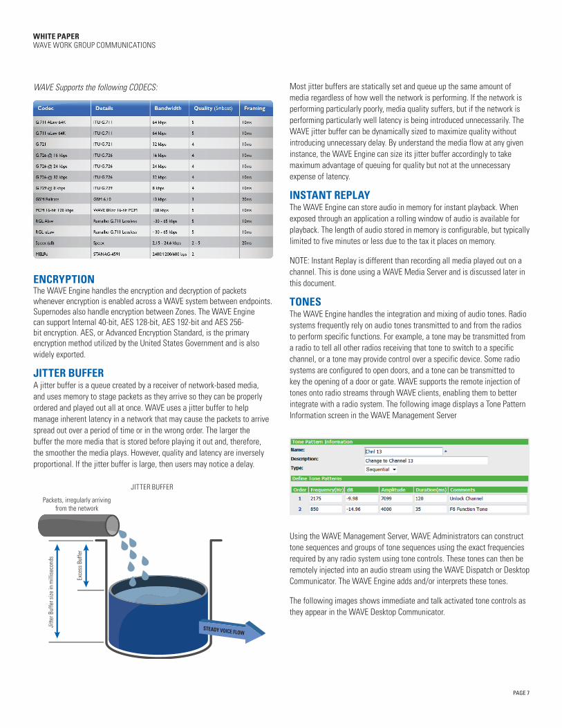
WAVE Supports the following CODECS:
ENCRYPTION The WAVE Engine handles the encryption and decryption of packets whenever encryption is enabled across a WAVE system between endpoints. Supernodes also handle encryption between Zones. The WAVE Engine can support Internal 40-bit, AES 128-bit, AES 192-bit and AES 256-bit encryption. AES, or Advanced Encryption Standard, is the primary encryption method utilized by the United States Government and is also widely exported.
JITTER BUFFER A jitter buffer is a queue created by a receiver of network-based media, and uses memory to stage packets as they arrive so they can be properly ordered and played out all at once. WAVE uses a jitter buffer to help manage inherent latency in a network that may cause the packets to arrive spread out over a period of time or in the wrong order. The larger the buffer the more media that is stored before playing it out and, therefore, the smoother the media plays. However, quality and latency are inversely proportional. If the jitter buffer is large, then users may notice a delay.
Most jitter buffers are statically set and queue up the same amount of media regardless of how well the network is performing. If the network is performing particularly poorly, media quality suffers, but if the network is performing particularly well latency is being introduced unnecessarily. The WAVE jitter buffer can be dynamically sized to maximize quality without introducing unnecessary delay. By understand the media flow at any given instance, the WAVE Engine can size its jitter buffer accordingly to take maximum advantage of queuing for quality but not at the unnecessary expense of latency.
INSTANT REPLAY The WAVE Engine can store audio in memory for instant playback. When exposed through an application a rolling window of audio is available for playback. The length of audio stored in memory is configurable, but typically limited to five minutes or less due to the tax it places on memory.
NOTE: Instant Replay is different than recording all media played out on a channel. This is done using a WAVE Media Server and is discussed later in this document.
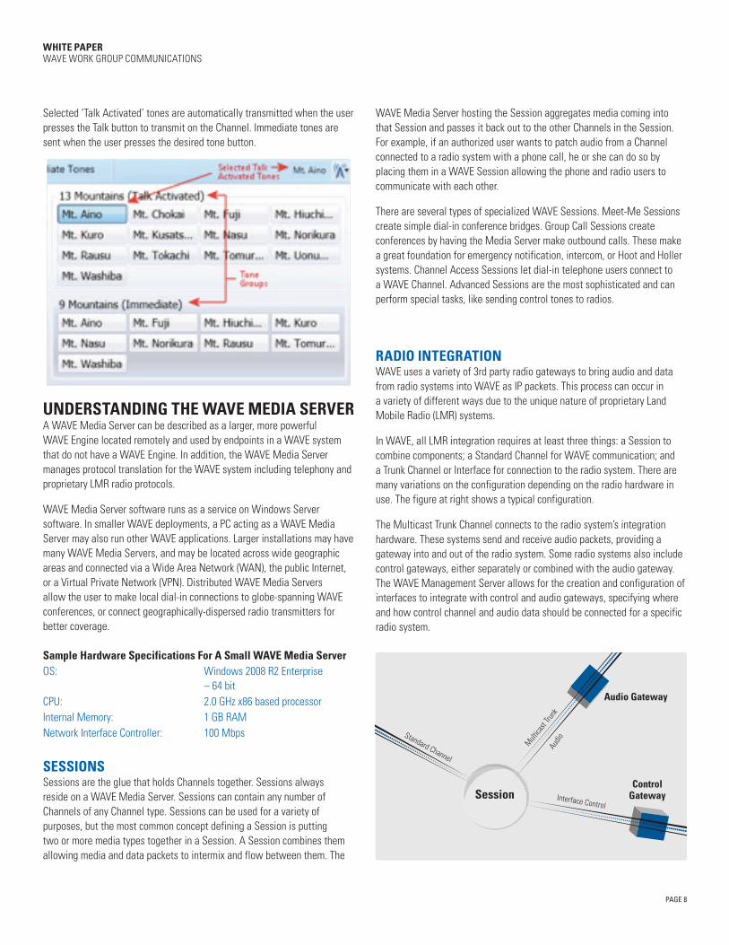
TONES The WAVE Engine handles the integration and mixing of audio tones. Radio systems frequently rely on audio tones transmitted to and from the radios to perform specific functions. For example, a tone may be transmitted from a radio to tell all other radios receiving that tone to switch to a specific channel, or a tone may provide control over a specific device. Some radio systems are configured to open doors, and a tone can be transmitted to key the opening of a door or gate. WAVE supports the remote injection of tones onto radio streams through WAVE clients, enabling them to better integrate with a radio system. The following image displays a Tone Pattern Information screen in the WAVE Management Server
Using the WAVE Management Server, WAVE Administrators can construct tone sequences and groups of tone sequences using the exact frequencies required by any radio system using tone controls. These tones can then be remotely injected into an audio stream using the WAVE Dispatch or Desktop Communicator. The WAVE Engine adds and/or interprets these tones.
The following images shows immediate and talk activated tone controls as they appear in the WAVE Desktop Communicator.
Packets, irregularly arrivingfrom the network
Jitte
r Buf
fer s
ize in
mill
isec
onds
Exce
ss B
uffe
r
JITTER BUFFER
PAGE 8
WHITE PAPER WAVE WORK GROUP COMMUNICATIONS
Selected ‘Talk Activated’ tones are automatically transmitted when the user presses the Talk button to transmit on the Channel. Immediate tones are sent when the user presses the desired tone button.
UNDERSTANDING THE WAVE MEDIA SERVER A WAVE Media Server can be described as a larger, more powerful WAVE Engine located remotely and used by endpoints in a WAVE system that do not have a WAVE Engine. In addition, the WAVE Media Server manages protocol translation for the WAVE system including telephony and proprietary LMR radio protocols.
WAVE Media Server software runs as a service on Windows Server software. In smaller WAVE deployments, a PC acting as a WAVE Media Server may also run other WAVE applications. Larger installations may have many WAVE Media Servers, and may be located across wide geographic areas and connected via a Wide Area Network (WAN), the public Internet, or a Virtual Private Network (VPN). Distributed WAVE Media Servers allow the user to make local dial-in connections to globe-spanning WAVE conferences, or connect geographically-dispersed radio transmitters for better coverage.
Sample Hardware Specifications For A Small WAVE Media ServerOS: Windows 2008 R2 Enterprise
– 64 bitCPU: 2.0 GHz x86 based processorInternal Memory: 1 GB RAMNetwork Interface Controller: 100 Mbps
SESSIONS Sessions are the glue that holds Channels together. Sessions always reside on a WAVE Media Server. Sessions can contain any number of Channels of any Channel type. Sessions can be used for a variety of purposes, but the most common concept defining a Session is putting two or more media types together in a Session. A Session combines them allowing media and data packets to intermix and flow between them. The
WAVE Media Server hosting the Session aggregates media coming into that Session and passes it back out to the other Channels in the Session. For example, if an authorized user wants to patch audio from a Channel connected to a radio system with a phone call, he or she can do so by placing them in a WAVE Session allowing the phone and radio users to communicate with each other.
There are several types of specialized WAVE Sessions. Meet-Me Sessions create simple dial-in conference bridges. Group Call Sessions create conferences by having the Media Server make outbound calls. These make a great foundation for emergency notification, intercom, or Hoot and Holler systems. Channel Access Sessions let dial-in telephone users connect to a WAVE Channel. Advanced Sessions are the most sophisticated and can perform special tasks, like sending control tones to radios.
RADIO INTEGRATION WAVE uses a variety of 3rd party radio gateways to bring audio and data from radio systems into WAVE as IP packets. This process can occur in a variety of different ways due to the unique nature of proprietary Land Mobile Radio (LMR) systems.
In WAVE, all LMR integration requires at least three things: a Session to combine components; a Standard Channel for WAVE communication; and a Trunk Channel or Interface for connection to the radio system. There are many variations on the configuration depending on the radio hardware in use. The figure at right shows a typical configuration.
The Multicast Trunk Channel connects to the radio system’s integration hardware. These systems send and receive audio packets, providing a gateway into and out of the radio system. Some radio systems also include control gateways, either separately or combined with the audio gateway. The WAVE Management Server allows for the creation and configuration of interfaces to integrate with control and audio gateways, specifying where and how control channel and audio data should be connected for a specific radio system.
Session
Audio Gateway
ControlGateway
Standard Channel
Multica
st Tru
nkAu
dio
Interface Control
PAGE 9
WHITE PAPER WAVE WORK GROUP COMMUNICATIONS
Sample Hardware Specifications for a WAVE Proxy ServerOS: Windows 2008 R2 Server 64-bitCPU: 8-core XEON Processor @ 2.0GHzInternal Memory: 64 GB RAMDisc Space: 5 GB Hard DriveNetwork Interface Controller: 1 Gigabit Ethernet NIC
TELEPHONY INTEGRATION IP telephony gateways enable WAVE to connect to IP-based telephone systems. As with LMR integration, this occurs through specific hardware gateways built by many different companies. H.323 and SIP are protocols both supported by WAVE.
As an example of telephony integration, consider a gateway to the Public Switched Telephone Network (PSTN). A PSTN gateway acts as a bridge between the VoIP calls originating from WAVE and phones on the PSTN (like a home or cell phone). Similarly, an IP telephony system or a digital PBX can function as gateways for WAVE, allowing the system to dial extensions behind those systems. WAVE Media Servers can also be gateways (in fact they’re configured that way on PBXs and IP Telephony systems), allowing Media Servers to call each other for purposes of establishing inter-Media Server trunk calls. In addition to H.323 and SIP Gateways, WAVE also supports H.323 and SIP Registrars or Gatekeepers containing registries of endpoints.
RECORDING Recording of media for archival purposes is also the responsibility of the WAVE Media Server. A Session hosted on a WAVE Media Server is responsible for recording audio. The Media Server places a recorder into the Session for a given Channel. The Session records the media and, at specific intervals, creates a media file with a unique filename. The file is then transmitted to the WAVE Management Server for archival storage. All WAVE recordings are ultimately stored on the WAVE Management Server unless a custom recording storage application has been installed on the WAVE Media Server.
PATCHING Patches are created on a Media Server when one or more channels or calls are placed into the same Session. The Media Server combines the streams from all of the different media sources enabling each channel or call to contain the media from all of the other streams. The patching algorithms have the intelligence to make sure audio loops are not created by placing the same media from multiple sources into the patch.
Some patches are permanent structures within WAVE that cannot be turned on or off through WAVE clients. Other patches can be activated or deactivated on the WAVE Dispatch Communicator. Temporary local patches can even be created by the dispatcher, allowing them to connect other Channels together during operation.
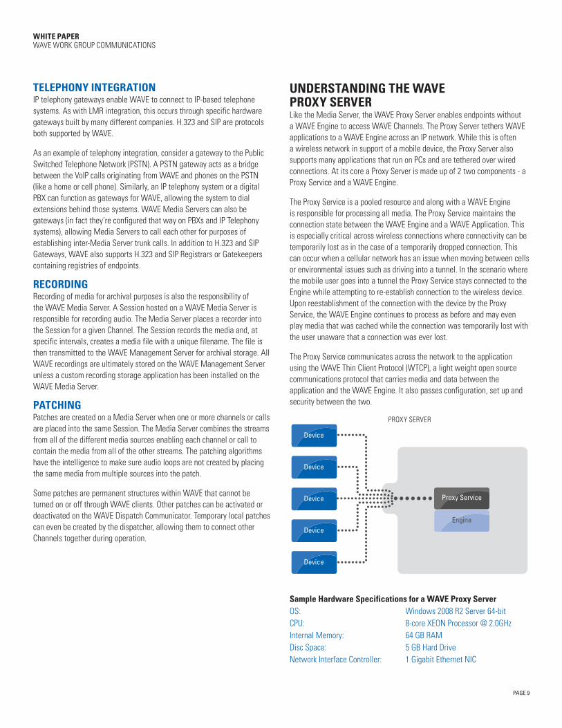
UNDERSTANDING THE WAVE PROXY SERVER Like the Media Server, the WAVE Proxy Server enables endpoints without a WAVE Engine to access WAVE Channels. The Proxy Server tethers WAVE applications to a WAVE Engine across an IP network. While this is often a wireless network in support of a mobile device, the Proxy Server also supports many applications that run on PCs and are tethered over wired connections. At its core a Proxy Server is made up of 2 two components - a Proxy Service and a WAVE Engine.
The Proxy Service is a pooled resource and along with a WAVE Engine is responsible for processing all media. The Proxy Service maintains the connection state between the WAVE Engine and a WAVE Application. This is especially critical across wireless connections where connectivity can be temporarily lost as in the case of a temporarily dropped connection. This can occur when a cellular network has an issue when moving between cells or environmental issues such as driving into a tunnel. In the scenario where the mobile user goes into a tunnel the Proxy Service stays connected to the Engine while attempting to re-establish connection to the wireless device. Upon reestablishment of the connection with the device by the Proxy Service, the WAVE Engine continues to process as before and may even play media that was cached while the connection was temporarily lost with the user unaware that a connection was ever lost.
The Proxy Service communicates across the network to the application using the WAVE Thin Client Protocol (WTCP), a light weight open source communications protocol that carries media and data between the application and the WAVE Engine. It also passes configuration, set up and security between the two.
Device
Device
Device
Device
Device
Proxy Service
Engine
PROXY SERVER
PAGE 10
WHITE PAPER WAVE WORK GROUP COMMUNICATIONS
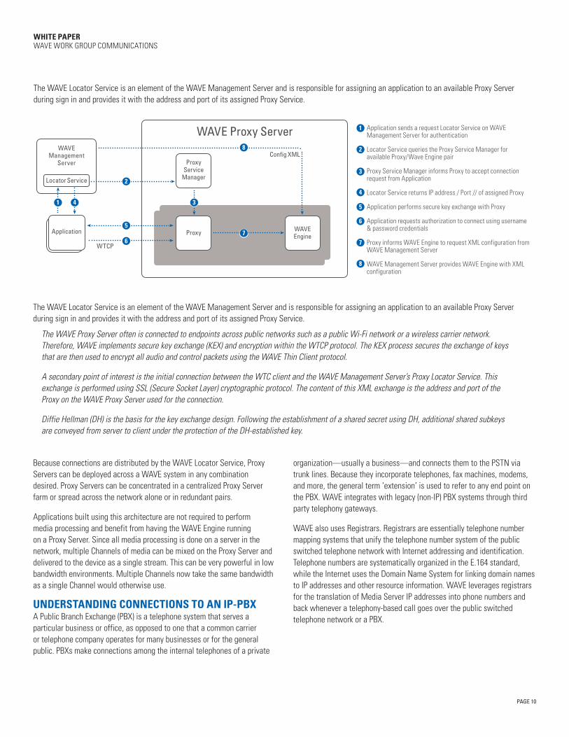
The WAVE Locator Service is an element of the WAVE Management Server and is responsible for assigning an application to an available Proxy Server during sign in and provides it with the address and port of its assigned Proxy Service.
The WAVE Locator Service is an element of the WAVE Management Server and is responsible for assigning an application to an available Proxy Server during sign in and provides it with the address and port of its assigned Proxy Service.
The WAVE Proxy Server often is connected to endpoints across public networks such as a public Wi-Fi network or a wireless carrier network. Therefore, WAVE implements secure key exchange (KEX) and encryption within the WTCP protocol. The KEX process secures the exchange of keys that are then used to encrypt all audio and control packets using the WAVE Thin Client protocol.
A secondary point of interest is the initial connection between the WTC client and the WAVE Management Server’s Proxy Locator Service. This exchange is performed using SSL (Secure Socket Layer) cryptographic protocol. The content of this XML exchange is the address and port of the Proxy on the WAVE Proxy Server used for the connection.
Diffie Hellman (DH) is the basis for the key exchange design. Following the establishment of a shared secret using DH, additional shared subkeys are conveyed from server to client under the protection of the DH-established key.
Because connections are distributed by the WAVE Locator Service, Proxy Servers can be deployed across a WAVE system in any combination desired. Proxy Servers can be concentrated in a centralized Proxy Server farm or spread across the network alone or in redundant pairs.
Applications built using this architecture are not required to perform media processing and benefit from having the WAVE Engine running on a Proxy Server. Since all media processing is done on a server in the network, multiple Channels of media can be mixed on the Proxy Server and delivered to the device as a single stream. This can be very powerful in low bandwidth environments. Multiple Channels now take the same bandwidth as a single Channel would otherwise use.
UNDERSTANDING CONNECTIONS TO AN IP-PBX A Public Branch Exchange (PBX) is a telephone system that serves a particular business or office, as opposed to one that a common carrier or telephone company operates for many businesses or for the general public. PBXs make connections among the internal telephones of a private
organization—usually a business—and connects them to the PSTN via trunk lines. Because they incorporate telephones, fax machines, modems, and more, the general term ‘extension’ is used to refer to any end point on the PBX. WAVE integrates with legacy (non-IP) PBX systems through third party telephony gateways.
WAVE also uses Registrars. Registrars are essentially telephone number mapping systems that unify the telephone number system of the public switched telephone network with Internet addressing and identification. Telephone numbers are systematically organized in the E.164 standard, while the Internet uses the Domain Name System for linking domain names to IP addresses and other resource information. WAVE leverages registrars for the translation of Media Server IP addresses into phone numbers and back whenever a telephony-based call goes over the public switched telephone network or a PBX.
1
2
3
4
5
6
7
8
Application sends a request Locator Service on WAVE Management Server for authentication
Locator Service queries the Proxy Service Manager for available Proxy/Wave Engine pair
Proxy Service Manager informs Proxy to accept connection request from Application
Locator Service returns IP address / Port // of assigned Proxy
Application performs secure key exchange with Proxy
Application requests authorization to connect using username & password credentials
Proxy informs WAVE Engine to request XML configuration from WAVE Management Server
WAVE Management Server provides WAVE Engine with XML configuration
WAVE Proxy ServerWAVE
Management Server
Locator Service
Application
Proxy Service
Manager
Config XML
WTCP
Proxy WAVE Engine
1 4
2
5
6
3
7
8
PAGE 11
WHITE PAPER WAVE WORK GROUP COMMUNICATIONS
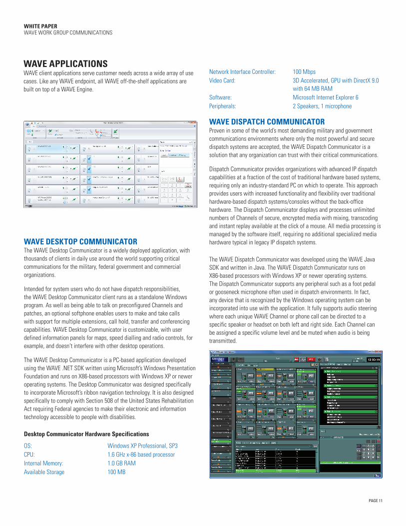
WAVE APPLICATIONS WAVE client applications serve customer needs across a wide array of use cases. Like any WAVE endpoint, all WAVE off-the-shelf applications are built on top of a WAVE Engine.
WAVE DESKTOP COMMUNICATOR The WAVE Desktop Communicator is a widely deployed application, with thousands of clients in daily use around the world supporting critical communications for the military, federal government and commercial organizations.
Intended for system users who do not have dispatch responsibilities, the WAVE Desktop Communicator client runs as a standalone Windows program. As well as being able to talk on preconfigured Channels and patches, an optional softphone enables users to make and take calls with support for multiple extensions, call hold, transfer and conferencing capabilities. WAVE Desktop Communicator is customizable, with user defined information panels for maps, speed dialling and radio controls, for example, and doesn’t interfere with other desktop operations.
The WAVE Desktop Communicator is a PC-based application developed using the WAVE .NET SDK written using Microsoft’s Windows Presentation Foundation and runs on X86-based processors with Windows XP or newer operating systems. The Desktop Communicator was designed specifically to incorporate Microsoft’s ribbon navigation technology. It is also designed specifically to comply with Section 508 of the United States Rehabilitation Act requiring Federal agencies to make their electronic and information technology accessible to people with disabilities.
Desktop Communicator Hardware Specifications
OS: Windows XP Professional, SP3CPU: 1.6 GHz x-86 based processorInternal Memory: 1.0 GB RAMAvailable Storage 100 MB
Network Interface Controller: 100 MbpsVideo Card: 3D Accelerated, GPU with DirectX 9.0
with 64 MB RAMSoftware: Microsoft Internet Explorer 6Peripherals: 2 Speakers, 1 microphone
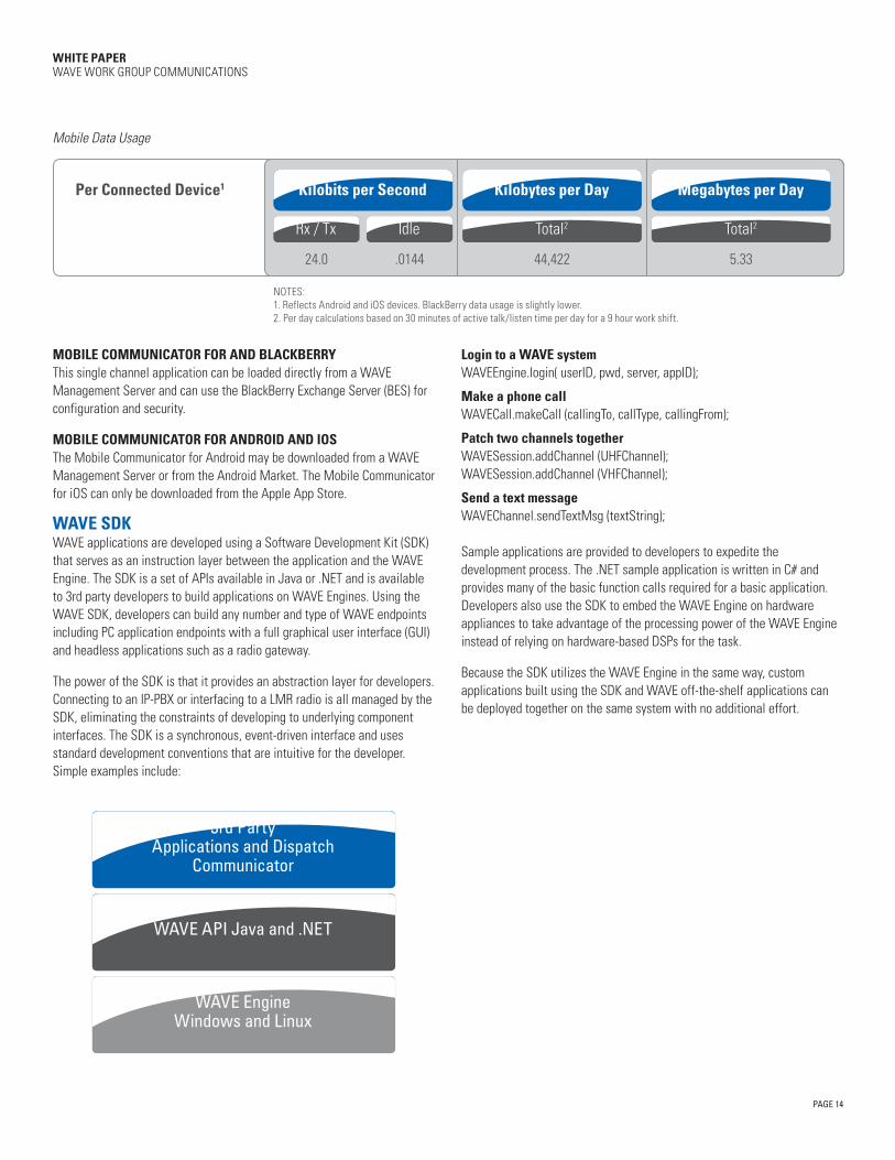
WAVE DISPATCH COMMUNICATOR Proven in some of the world’s most demanding military and government communications environments where only the most powerful and secure dispatch systems are accepted, the WAVE Dispatch Communicator is a solution that any organization can trust with their critical communications.
Dispatch Communicator provides organizations with advanced IP dispatch capabilities at a fraction of the cost of traditional hardware based systems, requiring only an industry-standard PC on which to operate. This approach provides users with increased functionality and flexibility over traditional hardware-based dispatch systems/consoles without the back-office hardware. The Dispatch Communicator displays and processes unlimited numbers of Channels of secure, encrypted media with mixing, transcoding and instant replay available at the click of a mouse. All media processing is managed by the software itself, requiring no additional specialized media hardware typical in legacy IP dispatch systems.
The WAVE Dispatch Communicator was developed using the WAVE Java SDK and written in Java. The WAVE Dispatch Communicator runs on X86-based processors with Windows XP or newer operating systems. The Dispatch Communicator supports any peripheral such as a foot pedal or gooseneck microphone often used in dispatch environments. In fact, any device that is recognized by the Windows operating system can be incorporated into use with the application. It fully supports audio steering where each unique WAVE Channel or phone call can be directed to a specific speaker or headset on both left and right side. Each Channel can be assigned a specific volume level and be muted when audio is being transmitted.

PAGE 12
WHITE PAPER WAVE WORK GROUP COMMUNICATIONS
Dispatch Communicator Hardware Specifications
OS: Windows XP Professional, SP3CPU: 2.0 GHz x-86 based processorInternal Memory: 1 GB RAMAvailable Storage 200 MBNetwork Interface Controller: 100 MbpsSoftware: Microsoft Internet Explorer 6Peripherals: 2 speakers, 1 microphone
WAVE SILVERLIGHT PLUG-INS WAVE utilizes Microsoft’s Silverlight technology that lends itself to integration within other applications. The Silverlight plug-in can display and process audio on WAVE channels and display users and presence information from within each channel. The Silverlight plug-ins integrates Bing maps into the application and share presence information from the channel(s) across onto the map display.
Silverlight plug-ins are used in conjunction with a WAVE Proxy Server as there is no WAVE Engine running on the host machine. At launch the plug-in checks for the availability of MSFT Silverlight on the machine. If it is not found, the application provides a prompt to download Silverlight before continuing. Today, the Silverlight plug-in has been integrated with the following systems:
WEB COMMUNICATORThe WAVE Web Communicator is built inside an HTML browser and supports Internet Explorer, Mozilla Firefox and Google Chrome.
WAVE COMMUNICATOR FOR MICROSOFT SHAREPOINTWAVE Communicator for Microsoft SharePoint is delivered as a web part for SharePoint Server 2007 and 2010. The web part can be embedded on a SharePoint page or as a link to launch is a separate window.
WAVE COMMUNICATOR FOR MICROSOFT LYNC 2010WAVE Communicator for Microsoft Lync runs in a Lync Conversation Window Extension. When called, the Lync Front-End Server queries the Lync Application Server where the WAVE Lync Channel Extension Manager (LCEM) application resides. WAVE LCEM, in turn, contacts the WAVE Management Server for configuration information and launches WAVE within the Lync Conversation Window Extension.

PAGE 13
WHITE PAPER WAVE WORK GROUP COMMUNICATIONS
SILVERLIGHT PLUG-IN HARDWARE SPECIFICATIONS
OS: Windows XP Professional, SP3CPU: 1.6 GHz x-86 based processorInternal Memory: 1.0 GB RAMAvailable Storage: 100 MBNetwork Interface Controller: 100 MbpsVideo Card: 3D Accelerated, GPU with DirectX
9.0 with 64 MB RAMSoftware: Microsoft Internet Explorer 6Peripherals: 2 Speakers, 1 microphone
WAVE MOBILE COMMUNICATORS Mobile Communicators are built specifically to run on the mobile operating system of today’s leading smartphones and tablets. Each application is connected to a WAVE system using a Proxy Server. There are two versions of the Mobile Communicator in production today – a single Channel and multi-Channel version. The single Channel version built for BlackBerry emulates a portable radio in a LMR system where the user has access to listen to and speak on one channel at a time. The multi-channel version built for Android and iOS operating systems provides access to many channels at once, much like WAVE PC-based applications. In addition to status and presence provided by the single channel applications, the multi-channel applications also provide a history of channel activity and mapping.
As described earlier one of the advantages of using a Proxy Server in these deployments is that media mixing is managed in the network. This allows multi-channel applications to provide media for many channels with the same bandwidth usage on the wireless network as a single channel application.
PAGE 14
WHITE PAPER WAVE WORK GROUP COMMUNICATIONS
3rd PartyApplications and Dispatch
Communicator
WAVE API Java and .NET
WAVE EngineWindows and Linux
Mobile Data Usage
MOBILE COMMUNICATOR FOR AND BLACKBERRYThis single channel application can be loaded directly from a WAVE Management Server and can use the BlackBerry Exchange Server (BES) for configuration and security.
MOBILE COMMUNICATOR FOR ANDROID AND IOSThe Mobile Communicator for Android may be downloaded from a WAVE Management Server or from the Android Market. The Mobile Communicator for iOS can only be downloaded from the Apple App Store.
WAVE SDK WAVE applications are developed using a Software Development Kit (SDK) that serves as an instruction layer between the application and the WAVE Engine. The SDK is a set of APIs available in Java or .NET and is available to 3rd party developers to build applications on WAVE Engines. Using the WAVE SDK, developers can build any number and type of WAVE endpoints including PC application endpoints with a full graphical user interface (GUI) and headless applications such as a radio gateway.
The power of the SDK is that it provides an abstraction layer for developers. Connecting to an IP-PBX or interfacing to a LMR radio is all managed by the SDK, eliminating the constraints of developing to underlying component interfaces. The SDK is a synchronous, event-driven interface and uses standard development conventions that are intuitive for the developer. Simple examples include:
Login to a WAVE systemWAVEEngine.login( userID, pwd, server, appID);
Make a phone callWAVECall.makeCall (callingTo, callType, callingFrom);
Patch two channels togetherWAVESession.addChannel (UHFChannel);WAVESession.addChannel (VHFChannel);
Send a text messageWAVEChannel.sendTextMsg (textString);
Sample applications are provided to developers to expedite the development process. The .NET sample application is written in C# and provides many of the basic function calls required for a basic application. Developers also use the SDK to embed the WAVE Engine on hardware appliances to take advantage of the processing power of the WAVE Engine instead of relying on hardware-based DSPs for the task.
Because the SDK utilizes the WAVE Engine in the same way, custom applications built using the SDK and WAVE off-the-shelf applications can be deployed together on the same system with no additional effort.
Kilobits per Second Kilobytes per Day Megabytes per Day
Rx / Tx Idle
24.0 .0144 44,422 5.33
Per Connected Device1
Total2 Total2
NOTES:1. Reflects Android and iOS devices. BlackBerry data usage is slightly lower.2. Per day calculations based on 30 minutes of active talk/listen time per day for a 9 hour work shift.
PAGE 15
WHITE PAPER WAVE WORK GROUP COMMUNICATIONS
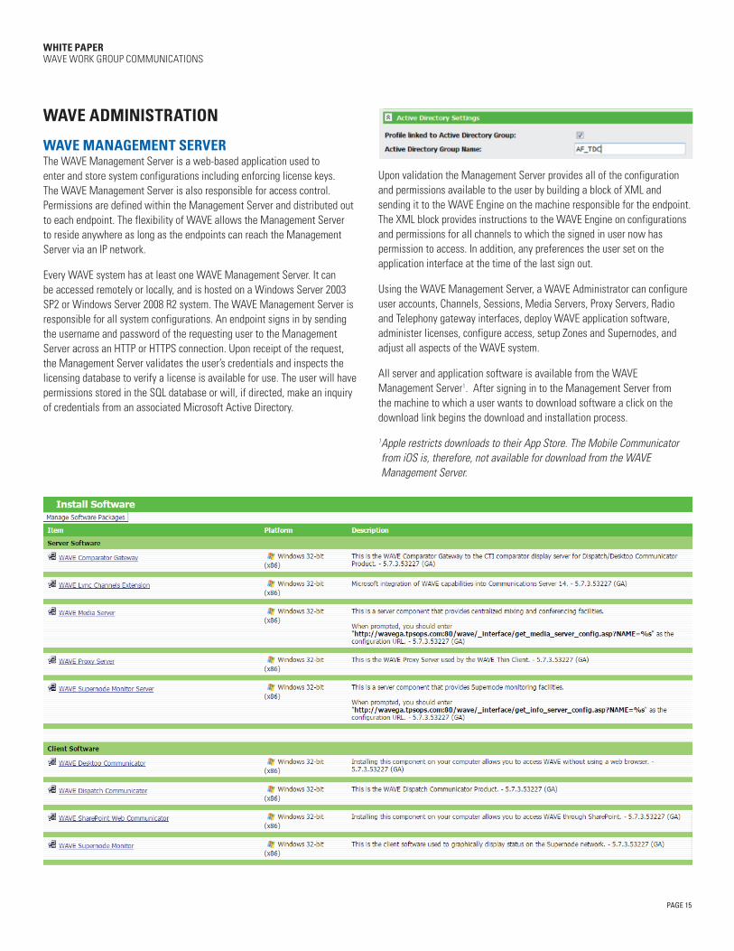
WAVE ADMINISTRATION
WAVE MANAGEMENT SERVER The WAVE Management Server is a web-based application used to enter and store system configurations including enforcing license keys. The WAVE Management Server is also responsible for access control. Permissions are defined within the Management Server and distributed out to each endpoint. The flexibility of WAVE allows the Management Server to reside anywhere as long as the endpoints can reach the Management Server via an IP network.
Every WAVE system has at least one WAVE Management Server. It can be accessed remotely or locally, and is hosted on a Windows Server 2003 SP2 or Windows Server 2008 R2 system. The WAVE Management Server is responsible for all system configurations. An endpoint signs in by sending the username and password of the requesting user to the Management Server across an HTTP or HTTPS connection. Upon receipt of the request, the Management Server validates the user’s credentials and inspects the licensing database to verify a license is available for use. The user will have permissions stored in the SQL database or will, if directed, make an inquiry of credentials from an associated Microsoft Active Directory.
Upon validation the Management Server provides all of the configuration and permissions available to the user by building a block of XML and sending it to the WAVE Engine on the machine responsible for the endpoint. The XML block provides instructions to the WAVE Engine on configurations and permissions for all channels to which the signed in user now has permission to access. In addition, any preferences the user set on the application interface at the time of the last sign out.
Using the WAVE Management Server, a WAVE Administrator can configure user accounts, Channels, Sessions, Media Servers, Proxy Servers, Radio and Telephony gateway interfaces, deploy WAVE application software, administer licenses, configure access, setup Zones and Supernodes, and adjust all aspects of the WAVE system.
All server and application software is available from the WAVE Management Server1. After signing in to the Management Server from the machine to which a user wants to download software a click on the download link begins the download and installation process.
1 Apple restricts downloads to their App Store. The Mobile Communicator from iOS is, therefore, not available for download from the WAVE Management Server.
PAGE 16
WHITE PAPER WAVE WORK GROUP COMMUNICATIONS
To learn more about WAVE, visit us online at motorolasolutions.com/WAVE
MOTOROLA, MOTO, MOTOROLA SOLUTIONS and the Stylized M Logo are trademarks or registered trademarks of Motorola Trademark Holdings, LLC and are used under license. All other trademarks are the property of their respective owners. ©2014 Motorola, Inc. All rights reserved.
The WAVE Management Server is used only for configuration and does not participate in real time media processing. This is an important aspect of WAVE eliminating any and all single points of failure. If for any reason the Management Server cannot be reached for sign in, some WAVE applications run on their last XML instructions stored in cache for up to 30 days. If the Management Server has not been reestablished in that time, subsequent logins will fail.
Management Server Hardware Specifications
OS: Windows 2003 ServerCPU: 2.0 GHz x-86 based processorInternal Memory: 512 MB RAMNetwork Interface Controller: 100 Mbps
SUMMARY The WAVE Work Group Communications solution is powerful, versatile communications software that creates communications channels and real-time access to those channels through a variety of end-user applications running on a variety of devices. Using WAVE, organizations have access to real-time, secure communications across any IP-based network.