wattch: a framework for architectural-level power analysis...
TRANSCRIPT

Wattch: A Framework for Architectural-Level Power Analysis and Optimizations
David Brooks Vivek Tiwari ’ Margaret Martonosi Department of Electrical Engineering Intel Corporation Department of Electrical Engineering
Princeton University Princeton University dbrooks@ee. princeton.edu vtiwari@scdt .intel.com mrm@ee. prince t on. edu
Abstract
Power dissipation and thermal issues are increasingly signif- icant in modern processors. As a result, it is crucial that power/performance tradeoffs be made more visible to chip architects and even compiler writers, in addition to circuit designers. Most existing power analysis tools achieve high accuracy by calculating power estimates for designs only af- ter layout or floorplanning are complete. In addition to be- ing available only late in the design process, such tools are often quite slow, which compounds the difficulty of running them for a large space of design possibilities.
This paper presents Wattch, a framework for analyz- ing and optimizing microprocessor power dissipation at the architecture-level. Wattch is lOOOX or more faster than ex- isting layout-level power tools, and yet maintains accuracy within 10% of their estimates as verified using industry tools on leading-edge designs. This paper presents several valida- tions of Wattch’s accuracy. In addition, we present three examples that demonstrate how architects or compiler writ- ers might use Wattch to evaluate power consumption in their design process.
We see Wattch as a complement to existing lower-level tools; it allows architects to explore and cull the design space early on, using faster, higher-level tools. It also opens up the field of power-efficient computing to a wider range of researchers by providing a power evaluation methodology within the portable and familiar Simplescalar framework.
1 Introduction
Until recently, power dissipation was an issue that primar- ily concerned designers of embedded or portable computer systems. Increasingly, however, power issues are becoming some of the primary design constraints for even very high- end microprocessors. As clock rates and die sizes increase, power dissipation is predicted to soon become the key limit- ing factor on the performance of single-chip microprocessors [13, 291. Already, current high-end microprocessors are be- ginning to reach the limits of conventional air cooling tech- niques. In addition to battery life and cooling concerns the difficulties of delivering large and highly-varying amounts of current onto the chip are also significant.
Voltage scaling and specialized circuit techniques have been the main strategies for low-power design, and these will continue to be important areas in the future. Unfortu- nately, these techniques alone are not sufficient; higher-level strategies for reducing power consumption are increasingly
Permission to make digital or hard copics of all or part of this work for personal or classroom use is granted without fee provided that copies are not made or distributed for profit or commercial advantage and that copies bear this notice and the full citation on the first page. To copy otherwise. to republrsh. to post on servers or to redistribute to lists, requires prior specific permission and/or a fee. ISCA 2000 Vancouver BC Canada Copyright ACM 2000 1-581 13-232-8/00/6...$5.00
crucial. Architectural and software techniques-in addition to lower-level circuit techniques-must play a major role in creating power-efficient computer systems.
Research in the area of high-performance, power-efficient computer architectures is still in its infancy. A major ob- stacle for such research has been the lack of infrastructure that analyzes and quantifies the power ramifications of dif- ferent architectural choices. Creating such infrastructure requires balancing the need for low-level detail and accu- racy against the need for higher-level abstractions offering simulator speed and portability.
This paper describes Wattch, an architectural simulator that estimates CPU power consumption. Our power esti- mates are based on a suite of parameterizable power models for different hardware structures and on per-cycle resource usage counts generated through cycle-level simulation. We see Wattch’s power modeling infrastructure as a useful and significant enabler of further research on architecture and compiler approaches for power efficiency.
1.1 Prior Work
We discuss related research in two categories. First, we touch on some relevant work on architecture-level techniques for reducing power consumption, and second, we discuss re- lated strategies for estimating power consumption at the architectural level.
Prior work in architecture-level techniques for power re- duction has mainly focused on caches [2, 16, 17, 271. This focus can be attributed to two factors. First, embedded mi- croprocessors, historically the main focus of low-power de- sign, frequently devote a large portion of their power budget to caches, in some cases up to 40% [20]. Second, since caches are regular structures, they are somewhat easier to model than other units, and thus, it can be easier to quantify power savings in caches.
Some work on architecture-level power reduction has ad- dressed other areas of the processor. For example, Manne et al. showed how branch prediction confidence estimators can be used to control branch speculation in order to re- duce power consumption [18]. This work presents results in terms of the amount of needIess speculative work saved per pipeline stage, as an indicator of power savings. Other prior work has discussed the power benefits of value-based clock gating in integer ALUs [6]. In both of these prior papers, a simple measure of the proposed strategy’s power effective- ness can be offered by quantifying some type of work that is “saved”. In one case, for example, this is the number of fruitless speculative cycles that were saved; in the other case, it is the number of result bits that need not be com- puted. While such work-saved measures are accurate and very useful for individual techniques, apples-to-apples com- parisons of different power-saving techniques require a single common power metric. This is our motivation for creating an architecture-level power simulator.
83

Finally, there has been prior work on architecture-level power estimation tools. For example, Chen et al. have de- veloped a system-level power analysis tool for a combined, single-chip 16-bit DSP and in-order 32-bit RISC micropro- cessor [8]. In this model, capacitance data was generated from switch-level simulation of the functional unit designs; thus, the models are not parameterizable. This simulator was demonstrated on short sequences of low-level assembly code benchmarks, and does not model out-of-order hard- ware, so it is difficult for us to compare the speed or accuracy of our approach with this related work.
Config 1
1.2 Contributions of this Work
One of the major shortcomings in the area of architecture- level power reduction is a high-level, parameterizable, sim- ulator framework that can accurately quantify potential power savings. Lower-level power tools such as PowerMzll [28] and QuickPower [19] operate on the circuit and Verilog level. While providing excellent accuracy, these types of tools are not especially useful for making architectural deci- sions. First, architects typically make decisions in the plan- ning phase before the design has begun, but both of these tools require complete HDL or circuit designs. Second, the simulation runtime cost for these tools is unacceptably high for architecture studies, in which the tradeoffs between many hardware configurations must be considered. The point of our work is not to compete with these lower-level tools, but rather to expose the basics of power modeling at a higher- level to architects and compiler writers. In a manner analo- gous to the development of tools for cycle-level architectural performance simulation, tools for architectural-level power simulation will help open the power problem to a wider au- dience.
This work’s goal is to demonstrate a fast, usefully- accurate, high-level power simulator. We quantify the power consumption of all the major units of the processor, param- eterize them where possible, and show how these power es- timates can be integrated into a high-level simulator. Our results indicate that Wattch is orders of magnitude faster than commercial low-level power modeling tools, while also offering accuracy in power estimates to within 10% of lower- level approaches. We hope that Wattch will help open the salient details of industry designs to the broader academic community interested in researching power-efficient archi- tectures and software.
Figure 1 shows three possible usage flows for Wattch. The left-most usage scenario applies to cases where the user is interested in comparing several design configurations that are achievable simply by varying parameters for hardware structures that we have modeled. The middle usage sce- nario is for software or compiler development, where a sin- gle hardware configuration is used and several programs are simulated and compared. The third usage scenario high- lights Wattch’s modularity. Additional hardware modules can be added to the simulator. In some cases, these hard- ware models follow the template of a hardware structure we already handle. For these cases (i.e., array structures) the user can simply add a new instantiation of the model into the simulator. For other types of new hardware, the model will not fit any already developed, but it is relatively easy to plug new models into the Wattch framework. In Section 4, we demonstrate case studies in which the power simulator can be used to perform these three types of power analysis.
Section 2 provides a detailed description of our power modeling methodology and Section 3 describes the valida- tion of the models against industrial data. Section 4 provides three case studies detailing how Wattch can be used to per-
Additional Hardware?
Binary
Watts-1 Watts-2
h a y Structure?
SimPower SimPower +II+
Custom Structure?
Watts-1 Watts-2
Use Current Estimate Power Models of Structure
SimPower
Scenario A: Scenario B: Microarchitectural tradeoffs Compiler Optimizations
Figure 1: Three scenarios for using architecture-level power analysis.
form microarchitectural tradeoff studies for low-power de- signs, compiler tradeoffs for power, and hardware optimiza- tions for low-power. In Section 5 we discuss future possibil- ities for research in the area of power-efficient architectures and provide conclusions.
2 Our Power Modeling Methodology
The foundations for our power modeling infrastructure are parameterized power models of common structures present in modern superscalar microprocessors. These power mod- els can be integrated into a range of architectural simulators to provide power estimates. In this work we have integrated these power models into the Simplescalar architectural sim- ulator [7].
Hardware Gmflg
I CyclC-LevCI
Estimate
I *
Figure 2: Overall Structure of the Power Simulator.
Figure 2 illustrates the overall structure of Wattch and
84

the interface between the performance simulator and the power models. In the following section we describe the power models in detail. We have performed both low-level and high-level validations of these models; we present these val- idation results in Section 3.
2.1 Detailed Power Modeling Methodology
The main processor units that we model fall into four cate- gories:
Array Structures: Data and instruction caches, cache tag arrays, all register files, register alias table, branch predictors, and large portions of the instruction win- dow and load/store queue.
0 Fully Associative Content-Addressable Memories: Instruction window/reorder buffer wakeup logic, load/store order checks, and TLBs, for example.
0 Combinational Logic and Wires: Functional Units, instruction window selection logic, dependency check logic, and result buses.
0 Clocking: Clock buffers, clock wires, and capacitive loads.
In CMOS microprocessors, dynamic power consumption (Pd) is the main source of power consumption, and is de- fined as: Pd = CV2daf. Here, c is the load capacitance, Vdd is the supply voltage, and f is the clock frequency. The activity factor, a, is a fraction between 0 and 1 indicating how often clock ticks lead to switching activity on average. Our model estimates C based on the circuit and the tran- sistor sizings as described below. V d d and f depend on the assumed process technology. In this work, we use the .35um process technology parameters from [21].
The activity factor is related to the benchmark programs being executed. For circuits that pre-charge and discharge on every cycle (i.e., double-ended array bitlines) an a of 1 is used. The activity factors for certain critical subcir- cuits (i.e., single-ended array bitlines) are measured from the benchmark programs using the architectural simulator. The vast majority of the nodes that have a large contribution to the power dissipation fall under one of these two categories. For subcircuits in which we are unable to measure activ- ity factors with the simulator (such as the internal nodes of the decoder) we assume a base activity factor of .5 (random switching activity). Finally, our higher-level power modeling selectively clock-gates unneeded units on each clock cycle, effectively lowering the activity factor.
The power consumption of the units modeled depends very much on the particular implementation, particularly on the internal capacitances for the circuits that make up the processor. We model these capacitances using assumptions that are similar to those made by Wilton and Jouppi [30] and Palacharla, Jouppi, and Smith [21] in which the authors performed delay analysis on many of the units listed above. In both of the above works, the authors reduced each of the above units into stages and formed RC circuits for each stage. This allowed them to estimate the delay for each stage, and by summing these, the delay for the entire unit.
For our power analysis we perform similar steps, but with two key differences. First, we are only interested in the capacitance of each stage, rather than both Rand C. Second, in our power analysis the power consumption of all paths must be analyzed and summed together. In contrast, when performing delay analysis, only the expected critical path is of interest. Table 1 summarizes our capacitance formulas, and the descriptions below elaborate on our approach.
Array Structures Our array structure power model is pa- rameterized based on the number of rows (entries), columns (width of each entry), and the number of read/write ports. These parameters affect the size and number of decoders, the number of wordlines, and the number of bitlines. In addition, we use these parameters to estimate the length of the pre-decode wires as well as the lengths of the array's wordlines and bitlines.
For the array structures we model the power consump- tion on the following stages: decoder, wordline drive, bit- line discharge, and output drive (or sense amplifier). Here we only discuss in detail the wordline drive and bitline dis- charge. These two components form the bulk of the power consumption in the array structures. Figure 3 shows a schematic of the wordlines and bitlines in the array struc- ture.
Node Regfile Wordline - Capacitance =
Regfile Bitline Capacitance =
CAM Tagline Capacitance =
CAM Matchline Capacitance =
Result Bus Capacitance =
Capacitance Equation Cdi f f (WordLineDriver) + CC,,t,(CellAccess) * NumBitlines 1 " ~. + Cmetal * WordLineLength Cdi f f (PreCharge) + Cd;fr(CellAccess) * NumWdlines --, , \ + Cmetal * BLLength C,,t,(CompareEn) * NumberTags + Cdiff(CompareDriver) + Cmetal * TLLength 2 * Cdiff(CompareEn) * TagSize + c d i f f (MatchPreCharge) + Cdi f f (Match0R) ., , + Cmetal * MLLength .5 * Cmetal * NumALU * ALUHeight) + Cmetal * (RegfileHeight)
Table 1: Equations for Capacitance of critical nodes.
Figure 3: Schematic of wordlines and bitlines in array struc- ture.
Modeling the power consumption of the wordlines and bitlines requires estimating the total capacitance on both of these lines. The capacitance of the wordlines include three main components. These three components are the diffusion capacitance of the wordline driver, the gate capacitance of the cell access transistor times the number of bitlines, and the capacitance of the wordline's metal wire.
85

The bitline capacitance is computed similarly. The to- tal capacitance is equal to the diffusion capacitance of the pre-charge transistor, the diffusion capacitance of the cell access transistor multiplied by the number of word lines, and the metal capacitance of the bitline. The models that we have created provide the option to use single-ended or double-ended bitlines. In this work we assume that register file array structures use single-ended bitlines and that cache array structures use double-ended bitlines. Equations for the wordline and bitline capacitance are shown in Table 1.
Multiple ports on the array structure will increase the power consumption in three ways. First, there will be more capacitance on the wordlines because each additional port requires an additional transistor connection. Second, each additional port requires up to two additional bitlines (bit and bit’), each of which must precharge/evaluate on every cycle. Finally, each core cell becomes larger which leads to longer word and bitlines, incurring additional wire capaci- tance.
Transistor sizing plays an important role in the amount of capacitance within the various structures. We use the transistor sizings of [21,30] wherever sizes are noted. Gener- ally, transistors in array structures are kept relatively small to reduce the area. In our model, certain critical transistors are automatically sized based on the model parameters to achieve reasonable delays. For example, the wordline driver transistor is critical for driving the wordline high in a short amount of time. The width of this transistor is scaled based on the amount of capacitance on the wordlines. Because of the length of the word and bitlines, the internal wiring capacitance of these structures is significant.
Our analysis is similar to Wilton and Jouppi’s study of cache array structures [30]. That work analyzes the access and cycle times for on-chip caches. We modify the analysis to take into account multi-ported array structures such as the register alias table, register file, etc. In addition, Kam- ble and Ghose developed power models for cache arrays to study power optimizations within caches [17] and Zyuban and Kogge studied low-power circuit techniques for register file structures [32].
The physical implementation of some array structures may be very different from the logical structure. For exam- ple, caches may be banked in order to provide reasonable delays. In this work we estimate the physical implementa- tions for cache structures using the help of the Cacti tool [30]. Cacti is a tool developed to determine delay-optimal cache hardware configurations given cache parameters such as size, block size, and associativity. We perform similar analysis on branch prediction structures to make them as square as possible in the physical implementation.
CAM Structures Our analysis of the CAM structures is very similar to that for array structures. However, in the CAM structure we model taglines and matchlines instead of bitlines and wordlines. Equations for the CAM tagline and matchline capacitance are shown in Table 1. Again we use a parameterized model which can be extended to the various CAM structures in the processor. We take into account the number of rows (number of tags), columns (number of bits per tag to match), and ports on the CAM. The analysis is similar to that for the array structures and follows the methodology taken in [21].
As an example, Figure 4 depicts the core cell of the in- struction wakeup logic which we model in our CPU as a form of the CAM structure. As described above, the key sizing parameters in this CAM are: (i) the issue/commit width of the machine (number of match or tag lines in each core cell, depicted by the parameter W in the figure), (ii) the instruc-
TagW Tag1 Dsts’ RAM Data Tagl’ TsgW ’ - ..
Ready
Figure 4: Core cell of wakeup logic modeled as a CAM.
tion window size (which impacts the CAM’s overall height) and (iii) the physical register tag size which equals logarithm base 2 of instruction window size (which impacts the CAM’s width). Vertically, each core cell is replicated Instruction- Windowsize times. Horizontally, the number of cells will equal the number of bits in the physical register tag; they share a common wide-OR for the final match which signals that the instruction is ready to issue. We also model the wordlines which are used to write new tag values into the CAM structure; for simplicity, these lines are omitted from the figure.
Complex Logic Blocks Two of the larger complex logic blocks that we consider are the instruction selection logic (in the instruction window) and the dependency check logic (in the register renaming unit). We model circuit structures based on the selection logic described in [21] and the depen- dency check logic in [3].
We model the power consumption of result buses by es- timating the length of the result buses using the same as- sumptions about functional unit height made in [22]. These lengths are multiplied by the metal capacitance per unit length. This equation is shown in Table 1.
Modeling the power consumption of the functional units (ALUs) at this high level would be difficult. Previous work has investigated the power consumption of various func- tional units [4, 311. We scale the power numbers from these combinational structures for process and frequency in order to estimate the power consumption of the functional units.
Clocking The clocking network on high performance mi- croprocessors can be the most significant source of power consumption. We consider three sources of clock power con- sumption:
Global Clock Metal Lines: Long metal lines route the clock throughout the processor. We model a modi- fied H-tree network in which the global clock signal is routed to all portions of the chip using equivalent length metal wires and buffers in order to reduce clock skew. This is similar to that used in the Alpha 21264
Global Clock Buffers: Very large transistors are used to drive the clock throughout the processor in a timely manner. We estimate the size and number of these transistors from [lo, 51.
Clock Loading: We consider both explicit and implicit clock loading. Explicit clock loads are the values of the gate capacitances of pre-charge transistors and other nodes that are directly connected to the clock within the units that we model. Implicit clock loads include
P O I .
86

the load on the clock network due to pipeline regis- ters. Here we use the number of pipeline stages in the machine and estimate the number of registers required per pipestage.
The models described above were implemented as a C program using the cacti tool [30] as a starting point. These models use Simplescalar's' hardware configuration parame- ters as inputs to compute the power consumption values for the various units in the processor. A summary of major hardware structures and the type of model used for each is given in Table 2.
Hardware Structure Instruction Cache Wakeup Logic Issue Selection Logic Instruction window Branch Predictor Register File Translation Lookaside Buffer Load/Store Queue Data Cache Integer Functional Units FP Functional Units Global Clock
-Model TfPe Cache Array (2x bitlines) CAM _ . ~ ~ ~
Complex combinational Array/CAM Cache Array (2x bitlines) Array ( lx bitlines) Array/CAM Array/CAM Cache Array (2x bitlines) Complex combinational Complex combinational Clock
Table 2: Common CPU hardware structures and the model type used by Wattch.
2.2 SimpleScalar Interface
The power models are interfaced with Simplescalar, which keeps track of which units are accessed per cycle and records the total energy consumed for an application. We use a modified version of Simplescalar's sim-outorder to collect results.
Simplescalar provides a simulation environment for mod- ern out-of-order processors with 5-stage pipelines: fetch, de- code, issue, writeback, and commit. Speculative execution is also supported. The simulated processor contains a uni- fied active instruction list, issue queue, and rename register file in one unit called the reservation update unit (RUU) [26]. Separate banks of 32 integer and floating point regis- ters make up the architected register file and are only written on commit. We have extended Simplescalar to provide for a variable number of additional pipestages between fetch and issue bringing the number of pipestages more in line with current microprocessors. In this study, we assume three ad- ditional pipestages between fetch and issue, and seven cycles of mispredict penalty.
Our power-oriented modifications track which units are accessed on each cycle and how. For example, if a particular cycle involves reading the instruction cache, selecting some ready instructions from the RUU, reading on two ports of the register file, and performing two integer additions, then the power models for each of these units will be invoked. Some of the power models vary the estimated power based on the number of ports used, as described in Section 2.2.1. As with most simulation frameworks, we hope that broader distribution of the framework will lead users to create an even richer variety of power modeling modules over time.
Section 4.1 describes further details of the baseline hard- ware parameters selected and the benchmarks we use.
2.2.1 Conditional Clocking Styles
One key issue that arises in estimating power concerns how to scale power consumption for multi-ported hardware units. Current CPU designs increasingly use conditional clocking to disable all or part of a hardware unit to reduce power con- sumption when it is not needed. In this work we consider three different options for clock gating to disable unused re- sources in multi-ported hardware. (More options can clearly be developed later; we give these as initial examples.)
The first and simplest clock gating style assumes the full modeled power will be consumed if any accesses occur in a given cycle, and zero power consumption otherwise. For example, a multi-ported register file would be modeled as drawing full power even if only one port is used. This as- sumption is realistic for many current CPUs that choose not to use ggressive conditional clocking. The second pos- sibility asstme, that if only a portion of a unit's ports are accessed, the power is scaled linearly. For example, if two ports of a 4-port register file are used in a given cycle, the power estimate returned will be one-half of the power if four ports are used. Wattch tracks how many ports are used on each hardware structure per cycle and scales power numbers accordingly. In practice, it may be impossible to totally shut off the power to a unit or port when it is not needed, so a small fraction of its total power may still be active. With this in mind, we also present a third option in which power is scaled linearly with port or unit usage, except that un- used units dissipate 10% of their maximum power, rather than drawing zero power. This number was chosen as it represents a typical turnoff figure for industrial clock-gated circuits.
W All or Nothing Clk Gating 0 Linear Clk Gating w/ 10%
Linear Clk Gating 40 35
gi 30
s ;: 15 10
5 0
Figure 5: Power consumption of benchmarks with condi- tional clocking on multi-ported hardware. The first bar as- sumes simple clock gating where a unit is fully on if any of its ports are accessed on that cycle, or fully off otherwise. The second bar assumes clock gating where the power scales linearly with port usage, and disabled ports consume 10% of their maximum power. The third bar assumes ideal clock gating where the power scales linearly with port usage as in the second bar, but disabled units are entirely shut off.
Figure 5 shows the power dissipation for the eight SPECint95 and four of the SPECfp95 benchmarks for the three styles of conditional clocking. The maximum power for this configuration (similar to the 21264) was 58.4W. Future processors are likely to move towards the more aggressive style to reduce the average power dissipation. We expect that there will be more variability in the power consump- tion of the benchmarks when more clock gating is used.
87

This assumption is supported by this figure: For the simple clock gating style, the maximum variations of the bench- marks from the average is 36%. The variations for the more advanced clock gating techniques are 54% and 66%. The amount of clock gating in current processors falls somewhere between the styles that we consider.
Wordline (w) Bitline (r) Bitline (w)
2.2.2 Simulation Speed
Wattch is intended to run with overheads only moderately larger than other Simplescalar simulators. It first computes the base power dissipation for each unit a t program startup, which is a one-time cost. These base power costs are then scaled with per-unit access counts. For arithmetic units, we only charge power for the units that would be used each cycle; a cycle that performs two integer additions will not be charged for the multiply unit. In addition to the access counts, the simulator also scales power estimates for multi- ported hardware based on the style of clock gating chosen from the options given in Section 2.2.1.
Our simulation speed measurements are for our modi- fied version of SimpleScalar/AXP’s sim-outorder running on a Pentium-I1 450MHz PC using RedHat Linux version 6.0. The simulation speed of sim-outorder without power model- ing was approximately 105K instructions per second. With our current methodology which updates the power statistics every cycle according to access counts, we see roughly a 30% overhead on average compared to performance simulation alone. That is, our simulation speed drops to roughly 80K instructions per second. Given the ability to gauge power at a fairly high level, we feel this overhead is quite tolera- ble. It can be further reduced, however, by updating power statistics every few cycles. This would require loosening the accuracy of the port count statistics and the statistics on the usage of different functional units.
As a comparison to lower level tools, running PowerMill on a 64-bit adder for 100 test vectors takes approximately one hour. In the same amount of time, Wattch can simulate a full CPU running roughly 280M Simplescalar instructions and generate both power and performance estimates.
-6.37 0.79 -10.68 -7.99 2.82 -10.58 -19.59 -10.91 -10.96 -10.60 7.98 -5.96
3 Model Validation
Validating the power models is crucial because fast power simulation is only useful if it is reasonably accurate. In this paper we provide three methods of validation. The first is a low-level check to compare the capacitance values generated from our model with those of real circuits. The second vali- dation level aims at quantifying the relative accuracy of our model. Namely, we compare the relative power weights that our model generates with experimentally-measured results from published works on industry chips. The final validation technique seeks to quantify the absolute magnitude accuracy of our models. With this method we compare the maximum processor power reported in published works with the power results of similar processor organizations generated from our models.
3.1 Validation 1: Model Capacitance vs. Physical
The parameterized power models presented in Section 2.1 obtain power dissipation estimates by calculating the ca- pacitance values on critical nodes within common circuits. Thus, a low-level method for validating the models is to com- pare the capacitance value computed by the model, against circuit design tool calculations of capacitance values for in- dustry schematics.
Schematics
In this section, we describe this type of validation for a 128-entry, 64-bit wide register file structure with 8 read ports and 6 write ports. The physical register file schematic was selected from the actual design for one of Intel’s IA-64 products. This type of large array structure is common in modern microprocessors and hence provides a good sample for our study.
Table 3 presents the results for validating the register file. We studied both the read and write nodes for the bit- lines and wordlines in the register file. The table breaks down the capacitance for each of these into gate capaci- tance, diffusion capacitance, and interconnect capacitance. For each entry, we present the percentage difference between the capacitance value estimated from a circuit-level capaci- tance extraction tool and the one calculated by our model. Most of the capacitance error rates are within +/-lo%. The largest sources of error were within the interconnect capaci- tance. There are two reasons for this. First, the capacitance of polysilicon wires is difficult to model, because the lengths of these wires vary with the physical layout. Second, it is dif- ficult to match the exact lengths of the interconnects in the physical schematic with the modeled nodes. For example, the wire in the bitline node in the physical schematic may extend beyond the length of the edge of the array structure, whereas our model assumes that the wire ends directly on the array boundary. Still, the total capacitance values are within 6-11% for the four nodes that were studied.
Array structures comprise roughly 50% of the total mod- eled chip power dissipation. We are currently performing similar low-level validation on other hardware structures such as CAM arrays. We expect that the results will be similar, since the methodology for modeling these units is identical.
3.2 Validation 2: Relative power consumption by struc-
Comparing low-level capacitance values is the most precise means of validating a power simulator. Unfortunately, we have access to only one set of industrial hardware designs and capacitance values. To validate our models against other chips, we present a second high-level set of valida- tion data. This data compares relative power of different hardware structures predicted by our model against pub- lished power breakdown numbers available for several high- end microprocessors. The downside to this comparison is that we have no way of knowing, whether the design style we model for each unit matches the design style that they actually use. In spite of this downside, it is reassuring to see that these power breakdowns track quite well. As shown in Tables 4 and 5, the relative power breakdown numbers for our models are within 10-13% on average of reported data.
Tables 4 and 5 compare breakdowns of Wattch’s power consumption for different hardware structures, with those from published data for the Intel Pentium Pro@ and Alpha
ture
88

Hardware Structure Instruction Fetch Register Alias Table Reservation Stations Reorder Buffer Integer Exec. Unit Data Cache Unit Memory Order Buffer Floating Point Exec. Unit Global Clock Branch Target Buffer
inm- 16 MEM 16 FP 64-INT 64-FP 8 4 4 4 4 3 Int 3 FP
N/A 5 12x2 N/A NIA NIB 32 entry
Intel Data I Model
Instr . Window(s)
Table 4: Comparison between Modeled and Reported Power Breakdowns for the Pentium Prom.
20 INT 15 FP
Out-of-Order Issue Logic
Floating Point Exec. Unit Integer Exec. Unit
11.7%
Table 5: Comparison between Modeled and Reported Power Breakdowns for the Alpha 21264.
Local History Table Local Predict Global History Register Global Predict Choice Predict BTB
21264 CPUs [13, 181. This power consumption is shown for “maximum power” operation, when all of the units are fully active. This mode of operation represents our static power estimates; we assume all of the ports on all of the units are fully active, with maximum switching activity. We did not actually modify SimpleScalar’s internal structure to resemble these processors. Instead we used the static power estimates from our models for the hardware configurations of the processors. The parameter configurations for our models are set based on published Intel and Alpha 21264 parameters [13, 141.
The power breakdowns track fairly well. For example, the Intel data in Table 4 is an exact or near match for several units. These include the data caches, instruction fetch and out-of-order control logic. The average difference between the power consumption of our modeled structures and the reported data was 13.3% for the Intel processor.
The relative power proportions for the Alpha 21264 are again similar to the reported data, with an average difference of 10.7%.
One unit which shows some inaccuracy in our current model is the global clock power for the Intel processor; our model predicts it to be 10% of total chip power, while the published data suggests it is less: 8%. This difference could be because the clock power model we use is based on an aggressive H-tree style that was used in Alpha 21264 [lo], but not in the Intel processor.
The Alpha 21264 has a significantly higher percentage of total clock power than Intel: 34% for the Alpha compared to 8% for the Intel processor. The main reason for this large difference is simply the method of accounting that is used for clock power by this two companies. The clock power cat- egory for 21264 includes all clock capacitance including the clock nodes within individual units. On the other hand, the Intel method for clock power accounting only counts clock power as the global clock network. Clock nodes that are internal to various hardware structures are counted towards
1024x10 N/A 1024x3 512x4
4096x2 N/A 4096x2 N/A 1K entry 512 entry 2-way 4-way
12 N/A
the power dissipation of those units. When we model these two different chips, we adjust our clock power accounting method to match that of the respective company’s data re- porting.
Finally, note that the power proportions we discuss here are normalized to the hardware structures that we consider. For example, since we do not model Intel’s complex x86 to micro-op decoding, we do not report the instruction decode unit power consumption, which consumes 14% of the chip power.
Feature Size .35um .35um Vdd 2.2v 3.3v MHz 600 200
3.3 Validation 3: Max power consumption for three CPUs
.35um 3.3v 200
Processor I Abha
Physical Registers 2~80-1NT I 72-FP Memory Order Queue Fetch width per cycle Decode width per cycle Issue width per cycle Commit width per cycle Functional Units
32 4 4 6 4 4 Int 2 F P
ch Predictil
entium El-EZ-l 20 UOPS
40 UOPs
20 3 6 3 3 4 Int 1 FP
which we compare the published maximum power numbers for three commercial microprocessors with the values pro- duced by our models for similar configurations. This allows us to evaluate both the relative and absolute accuracy of our power models. While such a comparison is difficult without exact process parameter information, general power trends can be seen based on the hardware organizations of these machines. Table 6 describes the details of the three proces- sors that we consider.
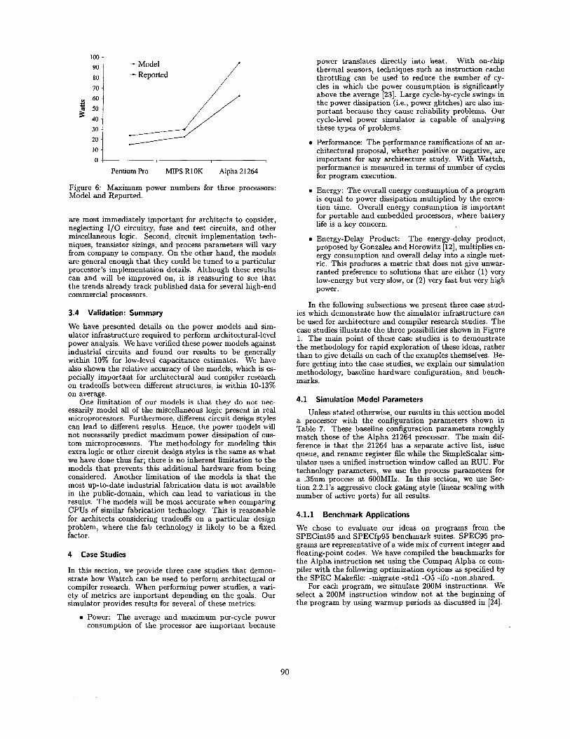
Figure 6 shows the results for the maximum power dis- sipation for the three processors that we considered. In all three cases, Wattch’s modeled power consumption was less than the reported power consumptions, on average 30% lower. There are a few reasons for this systematic under- estimation. First, we have concentrated on the units that
2-way
2-way
89
100 - Model - Reported
70 ///
I I
Pentium Pro MIPS RlOK Alpha 21264
Figure 6: Maximum power numbers for three processors: Model and Reported.
are most immediately important for architects to consider, neglecting 1/0 circuitry, fuse and test circuits, and other miscellaneous logic. Second, circuit implementation tech- niques, transistor sizings, and process parameters will vary from company to company. On the other hand, the models are general enough that they could be tuned to a particular processor’s implementation details. Although these results can and will be improved on, it is reassuring to see that the trends already track published data for several high-end commercial processors.
3.4 Validation: Summary
We have presented details on the power models and sim- ulator infrastructure required to perform architectural-level power analysis. We have verified these power models against industrial circuits and found our results to be generally within 10% for low-level capacitance estimates. We have also shown the relative accuracy of the models, which is es- pecially important for architectural and compiler research on tradeoffs between different structures, is within 10-13% on average.
One limitation of our models is that they do not nec- essarily model all of the miscellaneous logic present in real microprocessors. Furthermore, different circuit design styles can lead to different results. Hence, the power models will not necessarily predict maximum power dissipation of cus- tom microprocessors. The methodology for modeling this extra logic or other circuit design styles is the same as what we have done thus far; there is no inherent limitation to the models that prevents this additional hardware from being considered. Another limitation of the models is that the most up-to-date industrial fabrication data is not available in the public-domain, which can lead to variations in the results. The models will be most accurate when comparing CPUs of similar fabrication technology. This is reasonable for architects considering tradeoffs on a particular design problem, where the fab technology is likely to be a fixed factor.
4 Case Studies
In this section, we provide three case studies that demon- strate how Wattch can be used to perform architectural or compiler research. When performing power studies, a vari- ety of metrics are important depending on the goals. Our simulator provides results for several of these metrics:
Power: The average and maximum per-cycle power consumption of the processor are important because
power translates directly into heat. With on-chip thermal sensors, techniques such as instruction cache throttling can be used to reduce the number of cy- cles in which the power consumption is significantly above the average [23]. Large cycle-by-cycle swings in the power dissipation (i.e.] power glitches) are also im- portant because they cause reliability problems. Our cycle-level power simulator is capable of analyzing these types of problems.
Performance: The performance ramifications of an ar- chitectural proposal, whether positive or negative, are important for any architecture study. With Wattch, performance is measured in terms of number of cycles for program execution.
Energy: The overall energy consumption of a program is equal to power dissipation multiplied by the execu- tion time. Overall energy consumption is important for portable and embedded processors, where battery life is a key concern.
Energy-Delay Product: proposed by Gonzalez and Horowitz [12], multiplies en- ergy consumption and overall delay into a single met- ric. This produces a metric that does not give unwar- ranted preference to solutions that are either (1) very low-energy but very slow, or (2) very fast but very high power.
The energy-delay product, .
In the following subsections we present three case stud- ies which demonstrate how the simulator infrastructure can be used for architecture and compiler research studies. The case studies illustrate the three possibilities shown in Figure 1. The main point of these case studies is to demonstrate the methodology for rapid exploration of these ideas, rather than to give details on each of the examples themselves. Be- fore getting into the case studies, we explain our simulation methodology, baseline hardware configuration, and bench- marks.
4.1 Simulation Model Parameters
Unless stated otherwise, our results in this section model a processor with the configuration parameters shown in Table 7. These baseline configuration parameters roughly match those of the Alpha 21264 processor. The main dif- ference is that the 21264 has a separate active list, issue queue, and rename register file while the Simplescalar sim- ulator uses a unified instruction window called an RUU. For technology parameters, we use the process parameters for a .35um process at 6OOMHz. In this section, we use Sec- tion 2.2.1’s aggressive clock gating style (linear scaling with number of active ports) for all results.
4.1.1 Benchmark Applications
We chose to evaluate our ideas on programs from the SPECint95 and SPECfp95 benchmark suites. SPEC95 pro- grams are representative of a wide mix of current integer and floating-point codes. We have compiled the benchmarks for the Alpha instruction set using the Compaq Alpha cc com- piler with the following optimization options as specified by the SPEC Makefile: -migrate -stdl - 0 5 -if0 -nonshared.
For each program, we simulate 200M instructions. We select a 200M instruction window not at the beginning of the program by using warmup periods as discussed in [24].
90

Parameter I Value
L1 data-cache
L1 instruction-cache
L2
Memory TLBs
Processor Core RUU size I 64 instructions
; 32B blocks, 1 cycle latency 64K, 2-way (LRU) 32B blocks, 1 cycle latency Unified, 2M, 4-way (LRU) 32B blocks, 12-cycle latency 100 cycles 128 entry, fully associative 30-cycle miss latency
LSQ size Fetch Queue Size Fetch width Decode width Issue width Commit width Functional Units
Branch Predictor
32 instructions 8 instructions 4 instructions/cycle 4 instructions/cycle 4 instructions/cycle (out-of-order) 4 instructions/cycle (in-order) 4 Integer ALUs 1 integer multiply/divide 1 FP add, 1 FP multiply 1 FP dividelsart
BTB Return-address stack
, I
Branch Prediction I Combined, Bimodal 4K table
2-Level 1K table, lObit history 4K chooser 1024-entry, 2-way 32-entry
4.2 A Microarchitectural Exploration
One important application of Wattch is for microarchitec- tural tradeoff studies that account for both performance and power. For example, users may be interested in evaluat- ing sizing tradeoffs between different hardware structures. Clearly, the architectural decisions made when power is con- sidered may differ from those based solely on performance. One possible study which we consider in this section is to evaluate size tradeoffs between the RUU and data cache. This example demonstrates scenario A from Figure 1. The baseline processor configuration is that from Table 7 and our simulations vary the sizes of the RUU and D-cache. For all simulations, the Load/Store Queue is set to half the size of the RUU. We have collected these results for the SPECint95 and several of the SPECfp95 benchmarks. As we will dis- cuss below, the results typically fall into two main categories of behavior, and we present results for one representative benchmark from each category: gcc and turb3d.
Figures 7 ,8 and 9 show the results for the gcc benchmark. The three graphs show performance (in instructions per cy- cle), average power dissipation, and energy-delay product for the benchmark. Similarly, Figures 10, 11 and 12 show the same results for the turb3d benchmark.
The IPC graphs show that gcc gets significant perfor- mance benefit from increasing the data cache size. It only begins to level off a t roughly 64KB. In contrast, turbdd gets relatively little performance benefit from increasing the data cache size, but is highly sensitive to increases in the RUU size.
Although the performance contours are fairly different for these two benchmarks, the power contours shown in Fig- ures 8 and 11 are quite similar. Both show steady increases
in average power as the size of either unit is increased. Despite the similarity in the average power graph, the
two benchmarks do have strikingly different energy charac- teristics, as shown in Figures 9 and 12. The energy-delay product combines performance and power consumption into a single metric in which lower values are considered bet- ter both from a power and performance standpoint. The energy-delay product curve for gcc reaches its optimal point for moderate (64KB) caches and small RUUs. This indi- cates that although large caches continue to offer gcc small performance improvements, their contribdtion to increased power begins to outweigh the performance increase. RUU size offers little benefit to gcc from either a performance or energy-delay standpoint.
For turbdd, energy-delay increases monotonically with cache size, reflecting the fact that larger caches draw more power and yet offer this benchmark little performance im- provement in return. Moderate-sized RUU’s offer the opti- mal energy-delay for turbdd, but the valley in the graph is not as pronounced as for gcc.
Overall, the point of this case study is to demonstrate how the power simulator and the resulting graphs shown can help explore tradeoff points taking into account both power and performance related metrics.
4.3
This section gives an example of how a high-level power sim- ulation can be of use to compiler writers as well. We con- sider a simple case study which examines the effects of loop unrolling on processor power dissipation. Loop unrolling is a well-known compiler technique that extends the size of loop bodies by replicating the body n times, where n is the unrolling factor. The loop exit condition is adjusted accord- ingly. In this section, we consider a simple matrix multiply benchmark with 200x200 entry matrices. We have used the Compaq Alpha cc compiler to unroll the main loops in the benchmark, and we consider several unrolling factors.
Figures 13 shows the results for the execution time and power/energy results for loop unrolling. As one would hope, the execution time and the number of total instructions com- mitted decreases. This is because loop unrolling reduces loop overhead and address calculation instructions. The power results are more complicated, however, which makes the tradeoffs interesting in a power-aware compiler.
Figure 14 shows a breakdown of the power dissipa- tion of individual processor units normalized to the case with no unrolling. There are two important side-effects of loop unrolling. First, loop unrolling leads to decreased branch predictor accuracy, because the branch predictor has fewer branch accesses to “warm-up” the predictors and be- cause mispredicting the final fall-through branch represents a larger fraction of total predictions.
Another side-effect of loop unrolling is that removing branches leads to a more efficient front-end. The fetch unit is able to fetch large basic blocks without being interrupted by taken branches. This, in turn, provides more work for the renaming unit and fills up the RUU faster. In fact, with this example the RUU becomes full for an average of 85% of the execution cycles after we move from an unrolling factor of 2 to 4. The fetch queue, which connects the fetch unit to the renaming hardware is also affected, and is full for an average of 73% of the cycles at an unrolling factor of 4.
Thus, the average fetch unit power dissipation decreases for two reasons. First, because the branch prediction accu- racy has decreased, there are more misprediction stall cycles in which no instructions are fetched. The second reason is that at larger unrolling factors, the fetch unit is stalled dur-
Power Analysis of Loop Unrolling
91

Figure 7: IPC for gcc. Figure 8: Power for gcc. Figure 9: Energy-Delay Product for gcc.
Figure 10: IPC for turb3d Figure 11: Power for turb3d.
ing cycles when the instruction queue ani RUU are full. The reduced number of branch instructions also significantly re- duces the power dissipation of the branch prediction hard- ware. (Note that these stall cycles would increase the to- tal energy required to run the full program, but this graph shows average power.)
The renaming hardware, on the other hand, shows a small increase in power dissipation at an unrolling factor of two. This is because the front-end is operating at full-tilt, sending more instructions to the renamer per cycle. As the fetch unit starts to experience more stalls with unrolling fac- tors of 4 and beyond, the renamer unit also begins to remain idle more frequently, leading to lower power dissipation.
While the varied power trends in each unit are some- what complicated, the overall picture is best seen in Figure 13. The total instruction count for the program continues to decrease steadily for larger unrolling factors, even though the execution time tends to level out after unrolling by four. The combined effect of this is that energy-delay product con- tinues to decrease slightly for larger unrolling factors, even though execution time does not. Thus, a power-aware com- piler might unroll more aggressively than other compilers. This simple example is intended to highlight the fact that design choices are slightly different when power metrics are taken into account; Wattch is intended to help explore these tradeoffs.
4.4 Memoing To Save Power
Another important application for the Wattch infrastructure is in evaluating the potential hardware benefits of hardware optimizations. In this section, we consider result memoing,
Figure 12: Energy-Delay Product for turb3d.
a technique that [as been previously explored for perfor- mance benefits 19, 251. Memoing is the idea of storing the inputs and outputs of long-latency operations and re-using the output if the same inputs are encountered again. The memo table is looked up in parallel with the first cycle of computation, and the computation halts if a hit is encoun- tered. Thus memoing can reduce multi-cycle operations to one-cycle when there is a hit in the memo table.
We consider the power and performance benefits of this technique. Power consumption in the floating point units is reduced during memo table hits. On the other hand, the memo tables dissipate additional power. We base our analysis on [9], which showed that a small 32-entry, 4-way set associative table is capable of achieving reasonable hit rates.
Azam et al. have investigated a similar technique for sav- ing power within integer multipliers [l]. Their work did not model the additional power dissipation of reads and writes to the cache structure (only the tag comparison logic) and concentrated on integer and multimedia benchmarks. The point of this section is to demonstrate the methodology for using Wattch to perform such a study.
We have inserted memo tables in parallel with the floating-point and integer multipliers (4 cycles), the float- ing point adder (4 cycles), and the floating point-divider (16-cycles, unpipelined). Citron’s study examined the SPECfp95, Perfect, and a selection of multimedia and DSP applications finding that the multimedia applications have the lowest local entropy in result values and hence the high- est hit rates. Since Citron’s multimedia benchmarks were not readily available, we have examined a selection of bench- marks from the SPECfp95 suite. As in Citron’s work, we
92

14% 1
0.4
0.3
10% l 2 % 1 n
\ X
I
BPerformancc Speedup Power Savings
0 Energy Savings 0 Energy-Delay Improvement
* I I 0.8 a E
0.7
-e- Exec. lime
+Total
+-Power Instructions
+Energy * Delay
1
7 0.9 a 2 0.8 -e- total
* rename 0.7
+ bpred
5 0.5 .-C icache
0.4
0.3 1 2 4 5 8
Unroll Factor
Figure 14: Detailed Breakdown of Power Dissipation.
do not enter “trivial” operations such as multiplyfdivide by 0/1 into the table, because we assume that simpler hardware could recognize and capitalize on these opportunities.
The modifications to the power simulator infrastructure for the new hardware were not complex. The behavior of the memo tables was implemented and memo-tabZe-lookup and memo-table-write routines were inserted in the simula- tor pipeline. Both of these routines also serve as the access counters for the memo tables. The memo tables were mod- eled as simple cache array structures using the same power models that the other array structures use.
Figure 15 shows the performance and power results for the memoing technique. The benchmarks showed an aver- age speedup of 1.7% and an average power improvement of 5.4%. The larger power benefits of the memoing techniques are most likely due to the dynamically scheduled out-of- order execution core of the simulated processor. In an out- of-order processor, the delay of long-latency operations can often be hidden by finding other instructions to execute, thus the performance benefits of removing long-latency opera- tions are not too large. However, stopping these operations after one cycle of execution can have a significant impact on
8%
6%
4%
2%
0% aPPlu fpppp hydro2d mgrid turbfd
Figure 15: Performance and Power Effects of Memoing Tech- nique.
power dissipation. This is most apparent in mgrid, which shows almost no performance benefit, but just over an 8% power benefit.
5 Discussion and Conclusions
The goal of this work is to provide a simulator framework that can be used to evaluate a wide range of architectural and compiler techniques. Wattch has the benefit of low-level validation against industry circuits, while opening up power modeling to researchers at abstraction levels above circuits and schematics.
Wattch still has room for improvement and we hope that exposure and distribution to the architectural community will lead to the development of additional modules. Addi- tional accuracy validations are important, and we plan to compare the models against lower-level tools on more de- signs. Speed-accuracy tradeoffs for signal activity factors are another area we will consider in the future.
Extensions to the simulator infrastructure and the creation of additional modules are topics of future re- search. The simulator infrastructure could be extended to consider different hardware organization styles. Ad- ditional power modules could be developed with differ- ent circuit-implementation styles targeting different power- performance targets. Modeling of off-chip communication is also an important module to be developed. Additional work can also focus on more automatic transistor sizing and the effects of future process technologies, including leakage power dissipation.
We see a wide range of power studies that can be per- formed with Wattch. First, many old techniques may take on a new light when power is considered as a metric. The memoing case study described in Section 4.4 is one example of this. Other interesting techniques to study with power as a metric would be value-prediction [ll] and instruction pre- processing [15]. The effects of the compiler techniques and operating system control on power dissipation, including the use of power dissipation as feedback in a profiling compiler, are another possible research area. Finally, Wattch can be used in power studies which explore techniques that focus on micro-architectural solutions to lower-level power problems. One example of this is dynamic thermal management tech- niques to reduce power dissipation when thermal emergen- cies occur due to high-power sections of applications. An- other example would be the evaluation and development of solutions for large, short-term, current spikes due to clock gating, which can cause problems with chip reliability.
93

Exploring these classes of ideas in the power domain will open up new research possibilities for architects. The Wattch simulator infrastructure described in this paper of- fers a starting point for such research efforts.
Acknowledgments
This work has been supported by research funding from the National Science Foundation and Intel Corp. In addition, Brooks currently receives support from a National Science Foundation Graduate Fellowship and a Princeton University Gordon Wu Fellowship.
References
[I] M. Azam, P. Franzon, W. Liu, and T. Conte. Low Power Data Processing by Elimination of Redundant Computa- tions. In Proc. of Znt'l Symposium on Low-Power Electronics and Design, 1997.
[2] R. I. Bahar, G. Albera, and S. Manne. Power and perfor- mance tradeoffs using various caching strategies. In Proc. of Znt '1 Symposium on Low-Power Electronics and Design, 1998.
[3] B. Bishop, T. Kelliher, and M. Irwin. The Design of a Regis- ter Renaming Unit. In Proc. of Great Lakes Symposium on
[4] M. Borah, R. Owens, and M. Irwin. Transistor sizing for low power CMOS circuits. ZEEE Zhmsactions on Computer- Aided Design of Integrated Circuits and Systems, 15(6):665- 71, 1996.
[5] W. J. Bowhill et al. Circuit Implementation of a 300-MHz 64- bit Second-generation CMOS Alpha CPU. Digital Technical Journal, 7(1):100-118, 1995.
[6] D. Brooks and M. Martonosi. Dynamically exploiting nar- row width operands to improve processor power and perfor- mance. In Proc. of the 5th Znt'l Symp. on High-Performance Computer Architecture, Jan. 1999.
[7] D. Burger and T. M. Austin. The Simplescalar Tool Set, Version 2.0. Computer Architecture News, pages 13-25, June 1997.
[8] R. Chen, M. Irwin, and R. Bajwa. An architectural level power estimator. In Power-Driven Microarchitecture Work- shop at ISCA25, 1998.
[9] D. Citron, D. Feitelson, and L. Rudolph. Accelerating multi- media processing by implementing memoing in multiplica- tion and division units. In Proceedings of the 8th Znt'l Conf. on Architectural Support for Programming Languages and Opemting Systems (ASPLOS- VZZZ), pages 252-261, Oct. 1998.
[lo] H. Fair and D. Bailey. Clocking Design and Analysis for a 6OOMHz Alpha Microprocessor. In ZSSCC Digest of Techni- cal Papers, pages 398-399, February 1998.
Using value prediction to increase the power of speculative execution hardware. ACM Thnsactions on Computer Systems, Aug. 1998.
[12] R. Gonzalez and M. Horowitz. Energy Dissipation in Gen- eral Purpose Microprocessors. ZEEE Journal of Solid-state
[I31 M. Gowan, L. Biro, and D. Jackson. Power considerations in the design of the Alpha 21264 microprocessor. In 35th Design Automation Conference, 1998.
[I41 L. Gwennap. Intel's P6 uses decoupled superscalar design. Microprocessor Report, pages 9-15, Feb. 16, 1995.
[15] Q. Jacobson and J. Smith. Instruction pre-processing in trace processors. In Proc. of the 5th Znt'l Symp. on High- Performance Computer Architecture, Jan. 1999.
(161 M. G. Johnson Kin and W. H. Mangione-Smith. The filter cache: An energy efficient memory structure. In Proc. of the 30th Znt? Symp. on Microarchitecture, Nov. 1997.
VLSI, 1999.
[ll] F. Gabbay and A. Mendelson.
Circuits, 31(9):1277-84, 1996.
[17] M. B. Kamble and K. Ghose. Analytical Energy Dissipation Models for Low Power Caches. In Pmc. of Znt'l Symposium on Low-Power Electronics and Design, 1997.
[I81 S. Manne, A. Klauser, and D. Grunwald. Pipeline gating: Speculation control for energy reduction. In Proc. of the 25th Znt? Symp. on Computer Architecture, pages 132-41, June 1998.
[I91 Mentor Graphics Corporation, 1999. [20] J. Montanaro et al. A 160-MHz, 32-b, 0.5W CMOS RISC
microprocessor. Digital Technical Journal, 9(2):49-62, 1996. (211 S. Palacharla, N. Jouppi, and J. Smith. Complexity-Effective
Superscalar Processors. In Proc. of the 24th Int'l Symp. on Computer Architecture, 1997.
[22] S. Palacharla, N. Jouppi, and J. Smith. Quantifying the Complexity of Superscalar Processors. In Univ. of Wisconsin Computer Science Tech. Report 1328, 1997.
Thermal management system for high performance PowerPC microprocessors. In Proceedings of CompCon '97, Feb. 1997.
[24] K. Skadron, P. S. Ahuja, M. Martonosi, and D. W. Clark. Branch prediction, instruction-window size, and cache size: Performance tradeoffs and simulation techniques. ZEEE " a c t i o n s on Computers, 48(11):1260-810, Nov. 1999.
[25] A. Sodani and G. Sohi. Dynamic instruction reuse. In Proc. of the 24th Znt'l Symp. on Computer Architecture, May 1997.
[26] G. S. Sohi and A. S. Vajapeyam. Instruction issue logic for high-performance, interruptible pipelined processors. In Proc. of the 14th Znt'l Symp. on Computer Architecture, pages 27-34, June 1987.
[27] C. Su and A. Despain. Cache Designs for Energy Efficiency. In Proceedings of the 28th Hawaii Znt'l Conference on Sys- tem Science, 1995.
[23] H. Sanchez et al.
[28] Synopsys Corporation. Powermill Data Sheet, 1999. [29] V. Tiwari et al. Reducing power in high-performance micro-
processors. In 35th Design Automation Conference, 1998. [30] S. Wilton and N. Jouppi. An Enhanced Access and Cycle
Time Model for On-chip Caches. In WRL Research Report 93/5, DEC Western Research Laboratory, 1994.
[31] R. Zimmermann and W. Fichtner. Low-power logic styles: CMOS versus pass-transistor logic. ZEEE Journal of Solid- State Circuits, 32(7):1079-90, 1997.
[32] V. Zyuban and P. Kogge. The energy complexity of register files. In Proc. of Znt'l Symposium on Low-Power Electronics and Design, pages 305-310, 1998.
94