waterproofing of foundation - aquaflex
TRANSCRIPT

1
Waterproofing of Foundation I. General To use PVC geomembranes as a waterproofing for foundation is a sophisticated and safe technology to safe the construction against destructive influences of the water. Depending on the appearance of the water (Humidity, temporary water pressure, permanent water pressure) the lining system has to be adapted. This is expressed in the thickness of geomembrane and a system of control and repair. Under the influence of permanent water pressure a minimum thickness of 2,0 mm of the geomembrane has to be foreseen. This technical description explains the use of AQUAFOIL geomembranes for the waterproofing. II. The System
1. Foundation Slab
- lean concrete - geotextile of 500 g/m² - PVC geomembrane of 2,0
mm (1,5 mm) - Geotextile of 500 g/m² - PE sheet of 0,25 mm as
gliding layer - Protective concrete
As control and repair system water stops and injection pipes are installed. The surface of control areas should not overpass 100 m² in the foundation slab. Six (6) injection pipes is the minimum number to guarantee a correct injection result over the whole area. The foundation slab has to be separated through water stops from the wall section.
T.JEFFERSONLAAN 289, 2285AK,RIJSWIJK, THE NETHERLANDS TEL:+31-70-335-9306 FAX: +31-70-335-9305
2
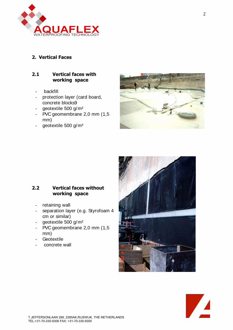
2. Vertical Faces
2.1 Vertical faces with working space
- backfill - protection layer (card board,
concrete blocks9 - geotextile 500 g/m² - PVC geomembrane 2,0 mm (1,5
mm) - geotextile 500 g/m²
2.2 Vertical faces without working space
- retaining wall - separation layer (e.g. Styrofoam 4
cm or similar) - geotextile 500 g/m² - PVC geomembrane 2,0 mm (1,5
mm) - Geotextile - concrete wall
T.JEFFERSONLAAN 289, 2285AK,RIJSWIJK, THE NETHERLANDS TEL:+31-70-335-9306 FAX: +31-70-335-9305

3
The same control and repair system is used as for the slab. The water stops are place in the joint or just near the joint of slab and wall. The surface of control areas has to be determined following the situation on site. III. Execution of the works:
1. Waterproofing with working space
1.1 Lining of the bottom slab
The lean concrete will be poured, after that the lining system has to be installed, existing of:
- Geotextile PP minimum 500 g/m², - Geomembrane AQUAFOIL PVC in a thickness, of at least 2, 0mm - Protection layer which can be a plastic sheet of 1,5 mm to 2,0 mm or a geotextile of minimum 500 g/m². It is absolutely recommended to put a PE-sheet on top of the geotextile in case this material is chosen as protection layer, to achieve a gliding between lean concrete and concrete slab. Besides the PE sheet avoids a penetration of liquid cement into the geotextile. - As last layer a protective concrete has to be poured. In case of using water stops the concrete may not be poured over them!! Otherwise the compartment system will not work.
Execution of Protective Concrete
T.JEFFERSONLAAN 289, 2285AK,RIJSWIJK, THE NETHERLANDS TEL:+31-70-335-9306 FAX: +31-70-335-9305

4
Excavation with working space
1.2 Lining between Slab and Wall
The lining system is over passing the concrete slab in order to be able to connect the waterproofing system of the wall. The waterproofing system - over passing the bottom slab - has to be protected (e.g. porous concrete) till the walls are constructed. Depending on the height of the wall, it will be constructed in successive steps. After finishing the concrete works of the wall (first section), the protective concrete (shown in the drawing above) will be removed, the connection between waterproofing system slab –wall can be executed. A very sensitive point for the lining is the change from horizontal slab to vertical wall. Local pressures at the corners mean serious stress; therefore it is very important to execute these areas with highest prudence.
T.JEFFERSONLAAN 289, 2285AK,RIJSWIJK, THE NETHERLANDS TEL:+31-70-335-9306 FAX: +31-70-335-9305
AQUFOIL PVC

5
Corner in 2 layers
1.3 Lining of Vertical Faces
The fixation on top of the wall can be executed in different ways. There is the possibility of placing a water stop into the upper side of the scaffolding. After the concreting the scaffolding is removed, the water stop cleaned and the membrane will be welded to the water stop. This is for sure a good technical solution and creates in addition a compartment system. In case the backfill follows the concrete works an intermediate fixation of the waterproofing system is also possible. To continue the waterproofing work after the backfill is brought to the desired height and the concrete of the next section of wall is executed the waterproofing follows. The intermediate fixation will be removed and the geomembrane will be welded underneath the area of the fixation to guarantee water tightness.
T.JEFFERSONLAAN 289, 2285AK,RIJSWIJK, THE NETHERLANDS TEL:+31-70-335-9306 FAX: +31-70-335-9305
AQUFOIL PVC
AQUFOIL PVC

6
System of the wall This procedure of work will continue till reaching the projected ending. The final fixation on the highest level can again be executed with the help of a water stop or a mechanical fixation.
T.JEFFERSONLAAN 289, 2285AK,RIJSWIJK, THE NETHERLANDS TEL:+31-70-335-9306 FAX: +31-70-335-9305
AQUFOIL PVC

7
2. Waterproofing without working space 2.1 Lining of the Bottom Slab
The execution of the bottom slab is similar to the case with working space besides the connection point for the wall lining. The waterproofing has to be fixed temporary to the retaining wall in such a height to guarantee a safe connection with the waterproofing of the wall.
Execution of the lining system between slab and wall
2.2 Lining of Vertical Faces
The waterproofing works are running before the concrete works of the walls. The waterproofing has to be brought to the height of the next concrete section for the walls and fixed intermediate over this level. When the lining works will be continued, the temporary fixation will be removed, the next part of the lining system welded to the installed membrane and placed over the vertical surface
T.JEFFERSONLAAN 289, 2285AK,RIJSWIJK, THE NETHERLANDS TEL:+31-70-335-9306 FAX: +31-70-335-9305
AQUFOIL PVC
AQUFOIL PVC

8
of the next section. In case the construction continues in this way, the described method will be repeated. (Sketch without water stops)
Intermediate Fixation of Waterproofing
T.JEFFERSONLAAN 289, 2285AK,RIJSWIJK, THE NETHERLANDS TEL:+31-70-335-9306 FAX: +31-70-335-9305
AQUFOIL PVC
AQUFOIL PVC

9
IV. Compartment system This system helps to narrow the repair works in case of damage. With the help of water stops, welded to the geomembrane, a compartment system will be established. The surface of one Compartment should not exceed 100 m². The water stops are of PVC and can be welded easily to the geomembrane. To weld the water stop to the membrane a welding automate can be used for horizontal surfaces. Depending on the joints (working joints or dilatation joints) an external water stop or an expansion water stop has to be used.
Protected Slab with exposed Water Stops
1. Water stops
1.1 Water stop for Expansion joint
T.JEFFERSONLAAN 289, 2285AK,RIJSWIJK, THE NETHERLANDS TEL:+31-70-335-9306 FAX: +31-70-335-9305
10
This water stop is placed in all dilatations of the construction. In case of important movements of the construction the middle bulb is able to break in the thin part on the bottom to follow the movements without loosing water tightness.
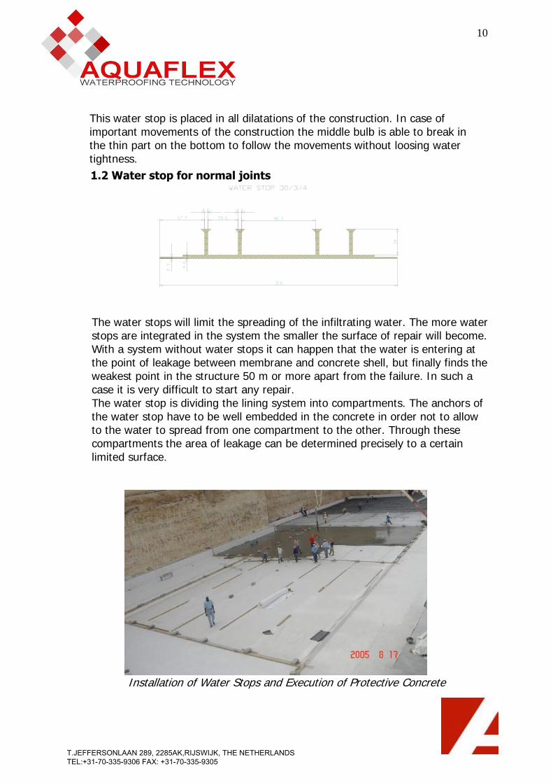
1.2 Water stop for normal joints
The water stops will limit the spreading of the infiltrating water. The more water stops are integrated in the system the smaller the surface of repair will become. With a system without water stops it can happen that the water is entering at the point of leakage between membrane and concrete shell, but finally finds the weakest point in the structure 50 m or more apart from the failure. In such a case it is very difficult to start any repair. The water stop is dividing the lining system into compartments. The anchors of the water stop have to be well embedded in the concrete in order not to allow to the water to spread from one compartment to the other. Through these compartments the area of leakage can be determined precisely to a certain limited surface.
Installation of Water Stops and Execution of Protective Concrete
T.JEFFERSONLAAN 289, 2285AK,RIJSWIJK, THE NETHERLANDS TEL:+31-70-335-9306 FAX: +31-70-335-9305

11
Execution of lining system with external water stops
Dangers of mechanical impact to Waterproofing system
T.JEFFERSONLAAN 289, 2285AK,RIJSWIJK, THE NETHERLANDS TEL:+31-70-335-9306 FAX: +31-70-335-9305

12
2. Injection pipes
Installed Injection Pipe spot welded to the Geomembrane
In addition to the water stops, injection pipes are welded punctually to the geomembrane. The task of the injection pipes is to give the possibility to inject liquid waterproofing materials in order to close the leakage of the geomembrane. These liquids or resins are based mostly on a two component acrylate or polyurethane. The injection pipes go through the concrete shell and are always reachable in case of a failure of the waterproofing system. The injection work is a difficult task and has to be executed by experts. The injection resin has to be pressed through the injection pipes between geomembrane and inside concrete. Very important is the mixture of the 2 component resin as it has to stay liquid long enough to spread over the whole surface of the compartment on one side, on the other side it has to harden quickly not to be evacuated by the infiltrating water.
Protected inlet of Injection Pipe
T.JEFFERSONLAAN 289, 2285AK,RIJSWIJK, THE NETHERLANDS TEL:+31-70-335-9306 FAX: +31-70-335-9305

V. Geomembrane
AQUAFOIL 226020205-20 : Geomembrane for tunnels and basement works withcalendared signal layer
1. Product
Calendered non-reinforced geomembrane, opaque, of flexible polyvinyl chloride (PVC-P), with calendered signal layer (PVC-P). Designed for tunnels and basement works. This geomembrane is not suitable for permanent exposure to UV-radiation. The use of a geomembrane with a thin «signal» layer of clear colour allows:
- A better inlighting in the tunnel under construction by the reverberation of the artificial lights.
- An easy visual detection of the damages caused to the geomembrane as well as during the installation and during the successive works. Indeed, if the geomembrane, locally, sustains a lost of thickness by mechanical, thermal or other aggression, the thin «signal» layer will be damaged, and will let appear the main lay of the geomembrane who is in dark.
2. Characteristics - Manufactured in an UNI EN ISO 9001 certified plant - Geomembrane with thin yellow signal layer (twin color) - Hardly combustible (B2 – DIN 4102) - Resistant to swelling, rotting and ageing - Very high level of watertightness, even with permanent deformation - Large capacity for adaptation to irregularities or deformation of support owing
to its high deformability and weld strength - High resistance to puncturing - Root resistance in accordance with DIN 4062 part 1 - Not resistant to bitumen, oil and tar
3. Installation
Hot air or hot wedge welding achieves assembly of the geomembrane. The weldability and the quality of the welding done on site can be influenced by
T.JEFFERSONLAAN 289, 2285AK,RIJSWIJK, THE NETHERLANDS TEL:+31-70-335-9306 FAX: +31-70-335-9305

14
atmospheric conditions (temperature, humidity of the air) and also by the state of the surface of the geomembrane (clean surface, more or less wetness of the surface) must be adapted in consequence. An anti-puncturing geotextile or composite protection (protection and draining) should be placed in position before the geomembrane, above any rough support. Generally when laying gravely sand, gravel, selected fill or concrete on a geomembrane, a geotextile or a protection membrane (protection against dynamicpuncturing) should be placed in between. The geomembrane can be used on a bituminous support after the insertion of a suitable separation layer.
4. Storage
Store in dry unheated space. Rolls to be parallel and in original packing. Do not stack in cross form or under pressure. The storage area must be of such a nature as not to damage the geomembrane.
5. Technical Data
Characteristics NORMS UNITS
Specifications
Thickness DIN 53370
mm 2,0 +-5%
Tensile strength DIN 53455
N/mm²
≥ 16
Elongation at failure DIN 53455
% L: ≥ 275 T: ≥ 275
Compressive strength at 20 % strain
DIN 53454
N/mm²
≥ 2,5
Tear propagation strength DIN 53363
N/mm
≥ 80
Resistance under water pressure
DIN 16726
Waterproof at 10 bar for 10 hours
T.JEFFERSONLAAN 289, 2285AK,RIJSWIJK, THE NETHERLANDS TEL:+31-70-335-9306 FAX: +31-70-335-9305
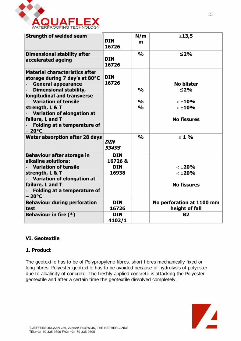
15
Strength of welded seam DIN 16726
N/mm
≥13,5
Dimensional stability after accelerated ageing DIN
16726
% ≤2%
Material characteristics after storage during 7 day’s at 80°C - General appearance - Dimensional stability, longitudinal and transverse - Variation of tensile strength, L & T - Variation of elongation at failure, L and T - Folding at a temperature of – 20°C
DIN 16726
%
% %
No blister ≤2%
< ±10% < ±10%
No fissures
Water absorption after 28 daysDIN 53495
% ≤ 1 %
Behaviour after storage in alkaline solutions: - Variation of tensile strength, L & T - Variation of elongation at failure, L and T - Folding at a temperature of – 20°C
DIN 16726 &
DIN 16938
< ±20% < ±20%
No fissures
Behaviour during perforation test
DIN 16726
No perforation at 1100 mm height of fall
Behaviour in fire (*) DIN 4102/1
B2
VI. Geotextile 1. Product The geotextile has to be of Polypropylene fibres, short fibres mechanically fixed or long fibres. Polyester geotextile has to be avoided because of hydrolysis of polyester due to alkalinity of concrete. The freshly applied concrete is attacking the Polyester geotextile and after a certain time the geotextile dissolved completely.
T.JEFFERSONLAAN 289, 2285AK,RIJSWIJK, THE NETHERLANDS TEL:+31-70-335-9306 FAX: +31-70-335-9305
16
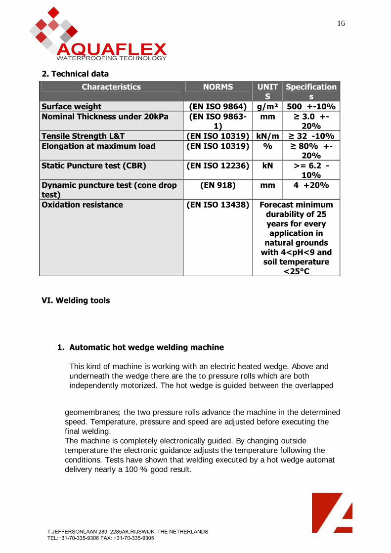
2. Technical data Characteristics NORMS UNIT
S Specification
s Surface weight (EN ISO 9864) g/m² 500 +-10%Nominal Thickness under 20kPa (EN ISO 9863-
1) mm ≥ 3.0 +-
20% Tensile Strength L&T (EN ISO 10319) kN/m ≥ 32 -10% Elongation at maximum load (EN ISO 10319) % ≥ 80% +-
20% Static Puncture test (CBR) (EN ISO 12236) kN >= 6.2 -
10% Dynamic puncture test (cone drop test)
(EN 918) mm 4 +20%
Oxidation resistance (EN ISO 13438) Forecast minimum durability of 25 years for every application in
natural grounds with 4<pH<9 and soil temperature
<25°C VI. Welding tools
1. Automatic hot wedge welding machine This kind of machine is working with an electric heated wedge. Above and underneath the wedge there are the to pressure rolls which are both independently motorized. The hot wedge is guided between the overlapped
geomembranes; the two pressure rolls advance the machine in the determined speed. Temperature, pressure and speed are adjusted before executing the final welding. The machine is completely electronically guided. By changing outside temperature the electronic guidance adjusts the temperature following the conditions. Tests have shown that welding executed by a hot wedge automat delivery nearly a 100 % good result.
T.JEFFERSONLAAN 289, 2285AK,RIJSWIJK, THE NETHERLANDS TEL:+31-70-335-9306 FAX: +31-70-335-9305

17
Automatic hot wedge welding machine
2. Automatic hot air welding machine The machine is a combination wedge automatic hot air welding machine. The hot air temperature, the pressure, and the speed welding are adjustable in step less way and electronically controlled.
Automatic hot air welding machine
3. Hand welder
The hand welder is working with hot air and is indispensable on a tunnel project. All details have to be executed with this well known device.
T.JEFFERSONLAAN 289, 2285AK,RIJSWIJK, THE NETHERLANDS TEL:+31-70-335-9306 FAX: +31-70-335-9305

18
Tunnel waterproofing is asking full concentration and precise work. A failure is leading to leakages which are difficult to repair and this only with important commercial means. The installer faces the problem that the following works can be responsible for the failure of the lining system. Therefore it is crucial that the contractor is fully aware of the sensitivity of the waterproofing work.
VII. Control and Testing of Waterproofing The whole waterproofing work has to be controlled carefully because the smallest leakage con lead to heavy problems in the future, therefore every seam executed on site or in prefabrication has to be tested. 1. Control of double seam through air pressure
The air canal is closed on both sides of the testing distance. A testing needle (e.g. type Leister) is introduced into the testing channel. The needle has a conical form to avoid the evacuation of the air under pressure. During the testing time of 10 minutes the needle may not be removed or manipulated. The applied testing pressure is of 2 bars. After 10 minutes of testing time the applied pressure must not reduce more than 20 %, due to the elongation capacity of the PVC-material. After successful testing a patch of PVC has to be welded over the penetration hole of the testing needle. The testing data will be noted in the testing document.
T.JEFFERSONLAAN 289, 2285AK,RIJSWIJK, THE NETHERLANDS TEL:+31-70-335-9306 FAX: +31-70-335-9305

19
Control devices for double machine welding Double seam control
Hand weldings
A scribbling iron (steel pipe connected to a compressor) with a diameter of 3 to 4 mm is drawn along the seam under an air pressure of 5 bars. Leakages are immediately detected though the developing air bulb due to the applied air pressure.
The execution of the waterproofing for foundations is a very difficult work which is demanding a maximum attention of the installer due to many details, difficult conditions on site and the fact that a repair of a leakage after the finishing of the construction is extremely expensive work.
T.JEFFERSONLAAN 289, 2285AK,RIJSWIJK, THE NETHERLANDS TEL:+31-70-335-9306 FAX: +31-70-335-9305