watereuse (phx) 2013-gary amy
TRANSCRIPT

Recent Developments in Low-Energy
Desalination Technologies:
Forward Osmosis, Membrane Distillation, and
Adsorption Desalination
Gary Amy, Noreddine Ghaffour, Suzana Nunes, Kim Choon Ng

Advances in Desalination
• Materials – Aquaporins (biomimetric membranes)
– Carbon Nanotubes (CNTs)
– Graphene
– Thin Film (inorganic-organic) Nanocomposites
– etc…
• Processes – Forward Osmosis (FO)
– Membrane Distillation (MD)
– Adsorption Desalination (AD)
– Capacitive Deioniniation (CDI)
– etc…

Process Total Energy (kW-h/m3)
Capital Cost ($/m3/d)
Unit Water ($/m3)
Multi Stage Flash/MSF (without waste heat) 55-57 - -
MSF (with waste heat) 10 - 16 1000 - 1500 0.8 -1.0
Multi Effect Distillation/MED (w/o waste heat) 40-43 - -
MED (with waste heat) 6 - 9 900 - 1200 0.6 – 0.8
Sea Water Reverse Osmosis/SWRO 3 - 6 800 - 1000 0.5 – 0.8
SWRO (with energy recovery) 2 - 3 < 800 0.45 – 0.6
Innovative Technologies/Hybridization < 2.0 * < 800 <0.5
(Source: Ghaffour and Ng, 2011)
* Thermodynamically minimum energy requirement for desalination 0.75 kWh/m3; <2.0 kWh/m3 attained by improving efficiency/hybridization
Thermal > SWRO > Innovative processes
Energy Requirements
• Conventional technologies: minimize energy requirements by waste heat, energy recovery
• Thermal desalination energy reduction by co-location with power plant

Wastewater Effluent
(low TDS)
H
H O
H
H O
H
H O
H
H O
H
H O
H
H O
H
H O H
H O
H
H O
H
H O
H
H O
H
H O
H2O
FO Membrane
H
H O
Organic Foulants (Humics, protein, etc.)
Heavy metals (Zn, Pb, Cu, Ni, Cr, Cd,
Mn, etc.)
Pollutants (NO3-, PO4
3-, EDCs, TORCs,
etc.)
H
H O
H
H O
H
H O
H
H O
H
H O
H
H O H
H O
H
H O
H
H O
H
H O
H
H O H
H O
H
H O
H
H O
H
H O
H
H O
H
H O
H
H O
H
H O H
H O
H
H O
H
H O
H
H O
O
Forward Osmosis (FO)
Water transport
driven by osmosis
Objective: Water (only) Extraction
Seawater (high TDS)

Forward Osmosis (FO) RO-like membrane,
but process is osmosis-driven not pressure-driven
Low energy alternative to SWRO Lower salinity or impaired quality
source (e.g. WW) as feed solution; higher salinity draw solution
Research Needs/ Process Improvements
New/better FO Membranes (open support layer; thickness and porosity)
Minimize internal concentration polarization (within support layer)
Assess/minimize fouling/biofouling Novel draw solutions
(seawater vs. synthetic solutions)
RO FO
RO brine
pump
Back pressure regulator
product water
Diluted
DS
Concentrated
DS
Figure 4. A combined FO/RO system

Draw Solution Need high solubility, low cost,
high osmotic pressure solution
Easily separable and reusable
Non-Toxic and eco-friendly
Post Treatment Recovery of product water from
diluted draw solution
Recovery and recirculation of
draw solution (components)
Concentrated feed: treatment
and/or environmental impact?
Need for Novel Draw Solutions

Direct FOD
Indirect FOD
Forward Osmosis
Desalination (FOD)
Company X
• (NaCl as DS with RO recovery)
• FO as Pretreatment RO?

FO
Wastewater
effluent
Concentrated Wastewater
effluent
Seawater
Diluted
seawater
Post-treatment
(lower salinity)
Post-treatment
(concentrated WW)
Forward Osmosis (FO) for Water Desalination and Reuse
in Coastal Cities
• Diluted Draw Solution: LPRO (fate of organic micropollutants & pathogens?)
• Concentrated Feed Solution: Anaerobic Treatment (primary effluent?)

FO Status: Membranes
• FO ≠ RO: Key focus on structure and
support layer, with goal of flux comparable
to RO
• Under development: Thin-film composite
membranes by interfacial polymerization
[Source: Peinemann, Nunes, 2008; Elimelch and Yip, 2010 (bottom)]
Thin-film composite membrane
interfacial polymerisation • New Membranes
• Development of high performance
thin-film composite (TFC)
membranes for FO application
• Polyamide active layer on top of
polysulfone support layer
• Finger like morphologies

FO + Nanoparticles Magnetic nanoparticles (MNPs) as
draw solution in FO
MNPs exert osmotic pressure, easily
recovered from draw solution by
applying magnetic field
FO + High MW Polyelectrolytes High MW polyelectrolytes, separable
by (low pressure) UF
Limitations/Research Needs MNPs and high MW polyelectrolytes'
size distribution, concentration in
draw solution, aggregation and
stability
Osmotic pressure (limited to brackish
water?)
Feed S
olu
tion
(low
er
osm
otic
pre
ssure
)
Dra
w S
olu
tion
(hig
her
osm
otic
Pre
ssure
)
Osmosis
(Source Chung, 2011)

The Ammonium-Carbonate Direct Desalination System (Elimelich, 2010)
Limitations:
• Energy Input
(if no waste heat)
• Residual Ammonia
• Carbonate Scaling


Pressure Retarded Osmosis
(PRO): A Special Case of FO
PRO • Pressure created by flow
of freshwater into salt water
• Pressure used to run a turbine
Blue energy
• In Norway,
River Water and Seawater
Research Questions • Develop PRO Membrane (PRO FO)
• Improve Power Efficiency (W/m2)
• Identify Applications
• Desalination Brine & Wastewater Effluent
• Piloting/Up-Scaling
Theoretical Yields
*
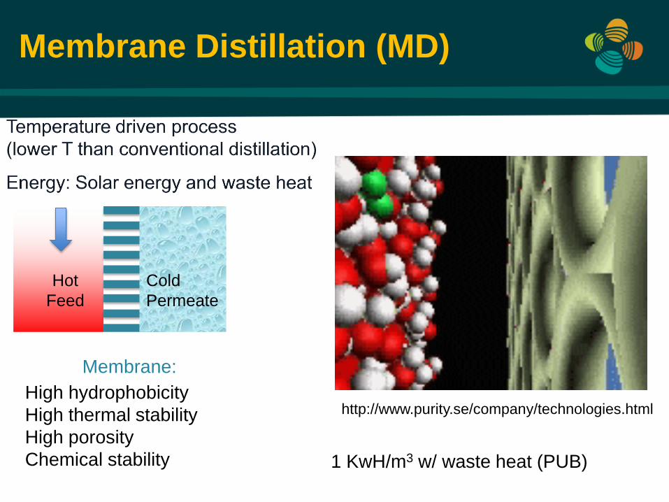
Membrane Distillation (MD)
http://www.purity.se/company/technologies.html High hydrophobicity
High thermal stability
High porosity
Chemical stability
Hot
Feed
Cold
Permeate
Membrane:
1 KwH/m3 w/ waste heat (PUB)

Membrane Distillation (MD) Evaporation process involving hydrophobic membrane Water vapor transported through membrane Temperature driven (lower than conventional distillation) Can be coupled with waste heat, or solar (solar-MD) MD applicable to extreme salinity (e.g.. Arabian Gulf) Little or no effect on flux Potential Application: MSF Brines; Produced Water
Research Needs Improved MD membranes, increased flux (85 LMH with 99.95% salt rejection with fabricated nanofiber membranes)
Reduce temperature polarization (through spacers) Process modeling and scale-up
Feed 90°C
60°C
Distillate
30°C
Distillate
60°C
Concentrate
Me
mb
ran
e
(Source: Ghaffour 2011, Tzahi Y. Cath 2008)
Flat sheet Hollow fiber Nanofiber
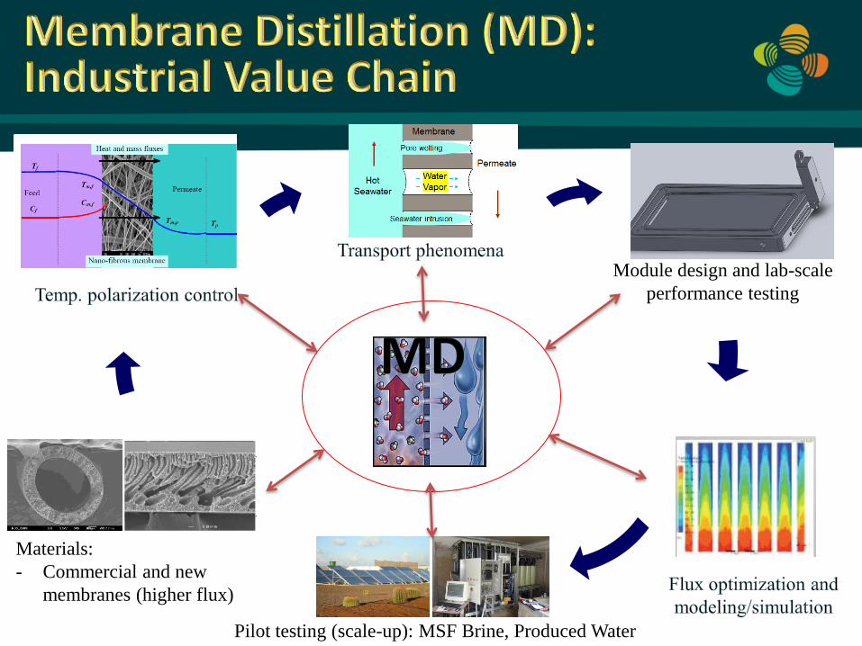
Materials:
- Commercial and new
membranes (higher flux)
Module design and lab-scale
performance testing
Pilot testing (scale-up): MSF Brine, Produced Water

FO + MD FO and MD integrated, FO is
employed to draw water from
dilute feed solution to concentrate
solution, and MD is used to
recover water from draw solution,
permitting recycling
Research Needs Feasibility/optimization of FO-MD
hybrid process in water treatment
and in desalination
Improved FO and MD membranes
to increase flux, minimize fouling
(Source: Chung, 2011)
Osmosis Heat
+ F
eed S
olu
tion
(low
er
osm
otic
pre
ssure
)
Dra
w S
olu
tion
(hig
her
osm
otic
Pre
ssure
)
Osmosis

Silica Gel (hydroscopic)
Water Vaporization
(at the Evaporator)
Silica Beads
Adsorption Desorption
(by Solar heat)
Condensed water Vapor
(at the Condenser)
Adsorption Desalination (AD) using Silica Gel
Adsorption and Desorption

AD Mesaporous
adsorbent, such as silica, is used to adsorb water vapor,
Heat (solar energy) is used to desorb water
Produces two useful effects (cooling and water desalination) with low temperature heat input (~65oC)
Low energy (1.4 kWh/m3 ) usage and no moving parts
Economical
Process kWh/m3* US$/m3
Thermal 6 -16 0.60-1.00
Membrane 3 - 6 0.45- 0.80
AD 1.4-1.9 0.29-0.30
* Total energy (includes thermal and electrical)

3 prototypes in Saudi Arabia and Singapore
1 commercial prototype in Poland
(Wroclaw University of Technology)
3 large Adsorption Desalination and Cooling
(ADC) planned for KSA
Saudi Arabia –KAUST, 10Rtons Solar Powered Singapore -45Rtons Each, Solar Powered Singapore –NUS 10Rtons, Waste Heat Prototype
Reaction
bed tower
Evaporator
Condenser
Purified
water
storage tank Reaction
bed tower
1
2 3
4
5
d d
H
( PCT/SG2009/ 000223, filing No. 61/226,783, No.: 61/297,347, PCT/SG2012/000076)

Microbial Fuel Cell (MFC) Covert chemical energy to electrical energy (bioelectricity) Two chambers, anode (oxygen starved /anaerobic) and cathode (oxygen rich/aerobic) Substrate (e.g., wastewater) introduced to anaerobic chamber, oxidized and releases electrons Electrons migrate toward cathode, in aerobic chamber
Microbial Desalination Cell (MDC) Third chamber, ions move from middle chamber to balance charge, due to protons produced by bacteria at the anode, protons removed at the cathode (Source: Bruce Logan, Penn State University)
What does this have to do w/ desalination? Third Cell with Electrodialysis (ED) Membranes:
Anion (AEM) and Cation (CEM) Exchange Membranes
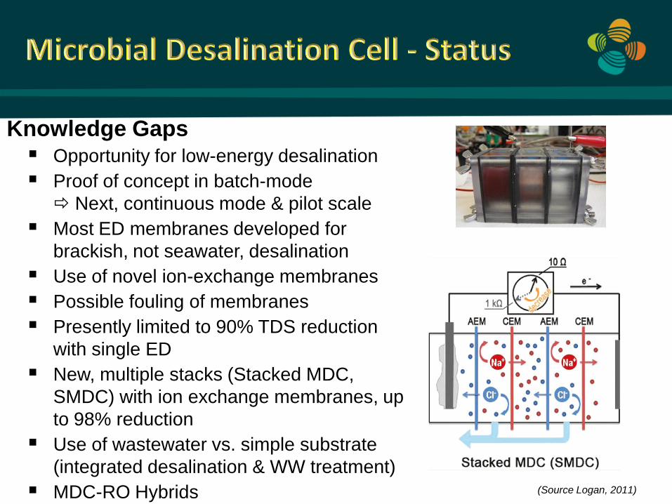
Knowledge Gaps Opportunity for low-energy desalination
Proof of concept in batch-mode
Next, continuous mode & pilot scale
Most ED membranes developed for
brackish, not seawater, desalination
Use of novel ion-exchange membranes
Possible fouling of membranes
Presently limited to 90% TDS reduction
with single ED
New, multiple stacks (Stacked MDC,
SMDC) with ion exchange membranes, up
to 98% reduction
Use of wastewater vs. simple substrate
(integrated desalination & WW treatment)
MDC-RO Hybrids (Source Logan, 2011)

Technology Integration Energy Recovery + Wastewater Treatment + Water Reuse

A Technology Roadmap for Low-Energy (-Cost) Desalination
Current
3.0 – 4.0 kWh/m3
Near Horizon
< 2.0 kWh/m3
Far Horizon:
Approach
1.0 kWh/m3
• Forward Osmosis (FO)
• Membrane Distillation (MD)
• Adsorption Desalination (AD)
• Microbial Desal. Cell (MDC)
• Microbial Osmotic FC (MOFC) • Seawater
Reverse Osmosis
(SWRO)

http://wdrc.kaust.edu.sa

Beyond Electrodialysis (ED)…
Electrodeionization (EDI) Similar to ED but also includes mixed-bed
ion-exchange resins between anion and cation membranes (to facilitate ion removals)
Capacitive Deionization (CDI) External electric charge applied on pair of
electrodes to feed water; ions migrate towards electrode of opposite charges and adsorb; in regeneration cycle, electric charge is turned off, adsorbed ions are released
Key Research Need Application to higher salinity waters
(seawater) What is salinity niche?