water to water heat pump operational manual
TRANSCRIPT

water to water heat pump
Operational Manual
Please read the manual first before install machines.
Please maintain manual for easy reference.

2
���� SSSSummaryummaryummaryummaryDF2SS-TS5 controller apply to water-cooled heat pump hot water heater, can control single or double
compressors, the controller consists of outdoor main board and indoor control panel, and have fan coil linkageinterface
���� MainMainMainMain technicaltechnicaltechnicaltechnical parametersparametersparametersparameters1﹑Operating conditions
□Operating voltage: AC220V±10%□Operating ambient temperature: -20~+55℃□Storage temperature: -35~+85℃□Moisture requirement: 0~95%RH
2﹑Temperature control precision: 1℃3﹑Controller conform to
□ GB4706.1-1988 《Household and similar electric appliances safety Part I: General Requirements》□ GB4706.32-1996 《Household and similar electric appliances safety, heat pump﹑ air-conditionersand dehumidifiers special requirements》□ GB18430.1-2001《Vapor compressor circulating cooling water(heat pump) units for industrial and
commercial use and similar purposes in cold water (heat pump) units》□ GB18430.2-2001《Vapor compressor circulating cooling water(heat pump) units for industrial and
commercial use and similar purposes in cold water (heat pump) units》□ AC noise interference conform to GB4343.2-1999□ Printed circuit board conform to GB4588.1 and GB4588.2 regulate
���� CCCControllerontrollerontrollerontroller functionsfunctionsfunctionsfunctions1、 Cooling running2、 Heating running3、 Show return water temperature of inner loop and preset temperature, with the inquiry functions4、 Automatic memory of the parameters if power fails.5、 The compressor runs balanced and start at different fixed time.6、 Short phase protection and inverse phase sequence protection of three-phase supply.7、 Perfect protection functions and displayed8、 Have fan coil linkage interface9、 Use Motorola high-performance chips, to have the best AC noise interference reduction.10、 ON/OFF at definite time function11、 Payment reminder function.
Note: in this document, “inside” mean is load side water loop., “outside” mean is heat source side waterloop.

3
���� OOOOperationperationperationperation ofofofof controlcontrolcontrolcontrol panelpanelpanelpanelIndoor control panel as follows :
1﹑ON/OFF□ Press”ON/OFF” button, the machine powers on , the indicator lamp ON□ Press”ON/OFF”button again,the machine powers off,the indicator lamp OFF□ Both ON and OFF mode ,data can be stored
2﹑Mode change□ Press“mode”button, choose needed the mode, “cooling” or “heating”mode□ “cooling”mode shown snow symbol□ “heating”mode shown sun symbol
3﹑Timing of NO/OFF(1) 〖b7〗 is 0 means combined definited time, (please read following section for setup):
□ Under power on mode, press“set time”button, power off at definite time..□ Under power off mode, press“set time”button, power on at definite time..□ Press “set time”button, “hour” time flash.□ Press”time ▽△”button, adjust definite “hour” time□ Press “set time”again,”minute” time flash.
4
□ Press”time ▽△”button, adjust definite “minute” time□ Press“set time”button again,the definite time setting is finished .□ Press”set time”button again ,definite time is canceled.
(2) Set 〖b7〗to 1 means set recurrent definite time□ Press“set time”button, “hour” time flash ,begin to set definite time for power on.□ Press ’time ▽△” button, adjust definite “hour” time for power on□ Press ”set time ’button again, ”minute” time flash□ Press”time ▽△”button, adjust definite “minute” time for power on□ Press ”set time ”button again,”hour” time flashes,the definite time setting for power on
is finished ,enter the definite time setting for power off□ Press ’time ▽△”button, adjust the definite “hour” time for power off□ Press “set time”button again, “minute” time flashes.□ Press”time ▽△”button, adjust the definite “minute” time for power off□ Press ”set time”button, the definite time setting for power off is finished.
(3) Clock setting□ Press”set time”button for 5 seconds, “hour” time flashes ,enter clock setting state .□ Press”time ▽△”button,to adjust the “hour” clock.□ Press ”set time “ again,”minute” time flashes .□ Press”time ▽△”button,to adjust the “minute” clock.□ Press ”set time”button again,clock setting is finished
4﹑Query□ Under recurrent definite time (〖b7〗is 1),press”check”button , will show real time.□ Press”check’ button,enter parameters inquiry state,press ”time ▽△”button again, can inquire about
the parameters of d1 d2 d3 d4 d5 , press ”time ▽△”button again, then quit the query state.□ Press”time ▽△”button ,to inquire about d1: inside loop outlet water temp,d2:inside loop return
water temp. d3: ambient air temp, d4:outside loop outlet water temp. D5:outside loop return watertemp.
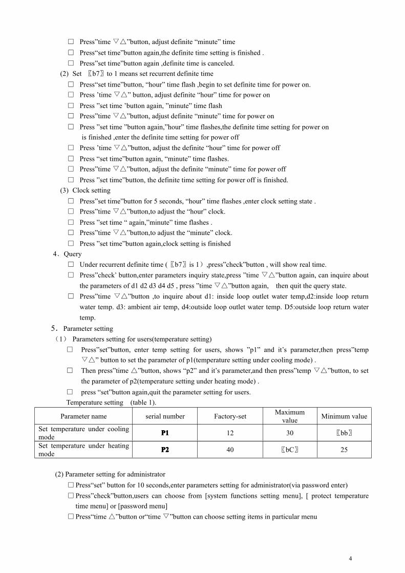
5.Parameter setting(1) Parameters setting for users(temperature setting)
□ Press”set”button, enter temp setting for users, shows ”p1” and it’s parameter,then press”temp▽△” button to set the parameter of p1(temperature setting under cooling mode) .
□ Then press”time △”button, shows “p2” and it’s parameter,and then press”temp ▽△”button, to setthe parameter of p2(temperature setting under heating mode) .
□ press “set”button again,quit the parameter setting for users.Temperature setting (table 1).
Parameter name serial number Factory-set Maximumvalue Minimum value
Set temperature under coolingmode P1P1P1P1 12 30 〖bb〗
Set temperature under heatingmode P2P2P2P2 40 〖bC〗 25
(2) Parameter setting for administrator□Press“set” button for 10 seconds,enter parameters setting for administrator(via password enter)□Press”check”button,users can choose from [system functions setting menu], [ protect temperature
time menu] or [password menu]□Press“time △”button or“time ▽”button can choose setting items in particular menu
5
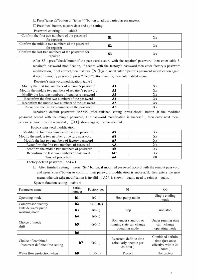
□Press“temp △”button or “temp ▽”button to adjust particular parameters.□Press“set” button, to store data and quit setting..Password entering : table2
Confirm the first two numbers of the passwordfor repairer S1S1S1S1 Xx
Confirm the middle two numbers of the passwordfor repairer S2S2S2S2 Xx
Confirm the last two numbers of the password forrepairer S3S3S3S3 Xx
After S3 , press”check”button,if the password accord with the repairer’ password, then enter table 3:repairer’s password modification, if accord with the factory’s password,then enter factory’s passwordmodification, if not correct,then it shows〖S1〗again, need enter repairer’s password modification again,if needn’t modify password, press “check”button directly, then enter table4 menu.Repairer’s password modification, table 3
Modify the first two numbers of repairer’s password A1A1A1A1 XxModify the middle two numbers of repairer’s password A2A2A2A2 Xx
Modify the last two numbers of repairer’s password A3A3A3A3 XxReconfirm the first two numbers of the password A4A4A4A4 Xx
Reconfirm the middle two numbers of the password A5A5A5A5 XxReconfirm the last two numbers of the password A6A6A6A6 Xx
Repairer’s default password: 555555, after finished setting, press”check” button ,if the modifiedpassword accord with the reinput password, The password modification is successful, then enter next menu,otherwise, modification is invalid , 〖A1〗shows again, need to re-input.
Facotry password modificationModify the first two numbers of factory password A7A7A7A7 Xx
Modify the middle two number of factory password A8A8A8A8 XxModify the last two numbers of factory password A9A9A9A9 Xx
Reconfirm the first two numbers of password AAAAAAAA XxReconfirm the middle two numbers of password AbAbAbAb Xx
Reconfirm the last two numbers of password ACACACAC XxTime of protection AdAdAdAd 00
Factory default password:654321□ After finished setting, press "Set" button, if modified password accord with the reinput password,
and press”check”button to confirm, then password modification is successful, then enters the nextmenu, otherwise,the modification is invalid ,〖A7〗is shown again, need to reinput again.
System function setting ,table 4
Parameter name serialnumber Factory-set 01 O0
Operating mode b1b1b1b1 1(0-1) Heat pump mode Single coolingmode
Compressor quantity b2b2b2b2 02(01-02)Outside water pumpworking mode b3b3b3b3 1(0-1) Stop non-stop
b4b4b4b4 1(0-1)
Choice of modeshift b5b5b5b5 0(0-1)
Both under stand-by orrunning state can change
operating mode
Under running statecan’t change
operating modebbbb6666
Choice of combined/recurrent definite time setting b7b7b7b7 0(0-1)
Recurrent definite time(circularly operate per
24-hour )
Combined definitetime (just once
effective within 24hours )
Water flow protection when b8b8b8b8 1(0-1) Protect Not protect

6
anti-freezingPhase protection choice b9b9b9b9 1(0-1) Protect Not protectCompressor restart
temperature difference bAbAbAbA 02(02-08)
The lower limit of cooling set bbbbbbbb 10(2-20)The upper limit of heating set bCbCbCbC 45(30-80)
Water temperature compensation bdbdbdbd 0(-10-+10) Without compensationwhen Anti-freezing mode
Times of protection bEbEbEbE 3(1-7)
Protection temperature time parameter , table 5Parameter name Unit
number
Factory setMaximum
valueMinimum
value
outside outlet water temperature too highprotection when cooling C1C1C1C1 55℃ 80℃ 30℃
inside outlet water temperature too low protectionwhen cooling C2C2C2C2 4℃ 10℃ 2℃
inside outlet water temperature too high protectionwhen heating C3C3C3C3 57℃ 90℃ 40℃
outside outlet water temperature too low protectionwhen heating C4C4C4C4 4℃ 10℃ -10℃
Inside return water and outlet water temperaturedifference too large protection C5C5C5C5 10℃ 15℃ 2℃
Outside return water and outlet water temperaturedifference too large protection C6C6C6C6 10℃ 15℃ 2℃
Temperature at which electric heating enteranti-freezing C7C7C7C7 5℃ 8℃ -2℃
Temperature at which compressor enter anti-freezing C8C8C8C8 3℃ 8℃ -2℃Protection of compressor start-up C9C9C9C9 3 Minutes 15Minutes 3MinutesTime of compressor running need to meet CACACACA 3 minutes 10 minutes 1 minuteTime of pressure checkout of shielding low pressure CbCbCbCb 3 minutes 60 minutes 0 minuteDuration of protection conditions CCCCCCCC 3 minutes 10 Seconds 1secondConsistent checkout time of water flow switch CdCdCdCd 10 seconds 30seconds 1secondInterval of compressor start -up CECECECE 30 seconds 90seconds 10seconds
Ø OutdoorOutdoorOutdoorOutdoor mainmainmainmain controlcontrolcontrolcontrol boardboardboardboard:Definition of interface, table 6
Name Number Marker ofinterface Functions Explanation Note
Analoginput
1 A01 Inside outlet water tempTemperature range :
-30~80℃L=2 meters
2 A02 Inside return water tempTemperature range:
-30~80℃L=5 meters
3 A03 Outside environmental temp Temperature range:-30~80℃
L=2 meters
4 A11 Outside outlet water temp Temperature range:-30~80℃
L=2 meters
5 A21 Outside return water tempTemperature range::
-30~80℃ L=2 meters
6 A31
Digital 1 I01 linkage control Dry contact inputsignal
Closenormally

7
input 2 I02 Inside water flow switch Dry contact inputsignal
3 I03 Inside anti-frost switch Dry contact inputsignal
4 I11 System 1 high pressure Dry contact inputsignal
5 I12 System 1 low pressure Dry contact inputsignal
6 I41 System 2 high pressureDry contact input
signal
7 I42 System 2 low pressureDry contact input
signal
8 I43 outside water flow switch Dry contact inputsignal
9 I31 Outside anti-frost switch Dry contact inputsignal
Digitaloutput
1 O01 Water pump 220VAC/20A
2 O02 Outside water pump 220VAC/7A
3 O11Auxiliary electric
heating220VAC/5A
4 O21 2#compressor 220VAC/5A
5 O22 1#compressor 220VAC/5A
6 O31 4-way valve 220VAC/5A
7 O41 Warning output 220VAC/5A
���� FunctionFunctionFunctionFunction descriptiondescriptiondescriptiondescription1. Temperature Controlling Object
Temperature Controlling Object is inside return water temperature
2.Functions choiceFunctions choice is according to table 3 setting item〖b1〗, if〖b1〗parameter is “1”,it is heat pump mode,
if “0”,it is single cooling mode.
3.Operating mode choiceOperating mode of system can be chosen as: cooling or heating . if 〖 b1〗 is “0”,it’s single cooling
mode,.the running mode is fixed cooling. if 〖b5〗 is “1”,then mode shift can be chosen under power ON/OFFstate,otherwise, it just can be chosen under power OFF state.
4. Linkage functionWhen wiring controller is OFF state, linkage connect, power ON, linkage disconnect, power OFFWhen wiring controller is ON state , Linkage connect, invalid, linkage disconnect, power off.
5. Outside water pump mode selectionWhen 〖b3〗 is “0”, choose outside water pump non-stop mode.When 〖b3〗 is “1”, choose outside water pump stop mode, if need start compressor , outside water pumpstart 1 minutes in advance , and after outside water pump has started for 1 minute, compressor can be
8
allowed start . And outside water pump should stop 1 minute later than compressor stop.
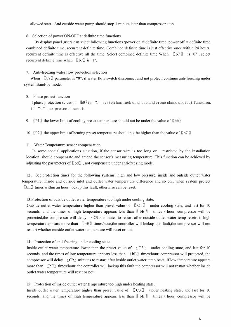
6.Selection of power ON/OFF at definite time functions.By display panel ,users can select following functions :power on at definite time, power off at definite time,
combined definite time, recurrent definite time. Combined definite time is just effective once within 24 hours,recurrent definite time is effective all the time. Select combined definite time When 〖b7〗 is "0" , selectrecurrent definite time when 〖b7〗is "1".
7. Anti-freezing water flow protection selectionWhen 〖b8〗parameter is “0”, if water flow switch disconnect and not protect, continue anti-freezing under
system stand-by mode.
8. Phase protect functionIf phase protection selection 〖b9〗is “1”,system has lack of phase and wrong phase protect function,
if “0”,no protect function.
9. 〖P1〗the lower limit of cooling preset temperature should not be under the value of〖bb〗
10.〖P2〗the upper limit of heating preset temperature should not be higher than the value of〖bC〗
11.Water Temperature sensor compensationIn some special applications situation, if the sensor wire is too long or restricted by the installation
location, should compensate and amend the sensor’s measuring temperature. This function can be achieved byadjusting the parameters of〖bd〗, not compensate under anti-freezing mode.
12.Set protection times for the following systems: high and low pressure, inside and outside outlet watertemperature, inside and outside inlet and outlet water temperature difference and so on., when system protect〖bE〗times within an hour, lockup this fault, otherwise can be reset.
13.Protection of outside outlet water temperature too high under cooling state.Outside outlet water temperature higher than preset value of 〖C1〗 under cooling state, and last for 10seconds ,and the times of high temperature appears less than 〖 bE 〗 times / hour, compressor will beprotected,the compressor will delay 〖C9〗minutes to restart after outside outlet water temp resetr; if hightemperature appears more than 〖bE〗times/hour,the controller will lockup this fault,the compressor will notrestart whether outside outlet water temperature will reset or not.
14.Protection of anti-freezing under cooling state.Inside outlet water temperature lower than the preset value of 〖C2〗 under cooling state, and last for 10seconds, and the times of low temperature appears less than 〖bE〗times/hour, compressor will protected, thecompressor will delay 〖C9〗minutes to restart after inside outlet water temp reset; if low temperature appearsmore than 〖bE〗times/hour, the controller will lockup this fault,the compressor will not restart whether insideoutlet water temperature will reset or not.
15.Protection of inside outlet water temperature too high under heating state.Inside outlet water temperature higher than preset value of 〖 C3 〗 under heating state, and last for 10seconds ,and the times of high temperature appears less than 〖 bE 〗 times / hour, compressor will be
9
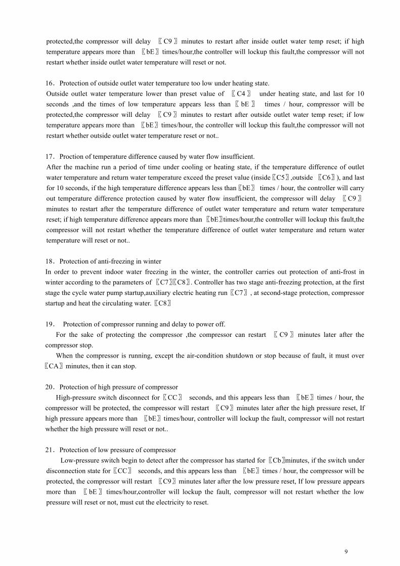
protected,the compressor will delay 〖C9〗minutes to restart after inside outlet water temp reset; if hightemperature appears more than 〖bE〗times/hour,the controller will lockup this fault,the compressor will notrestart whether inside outlet water temperature will reset or not.
16.Protection of outside outlet water temperature too low under heating state.Outside outlet water temperature lower than preset value of 〖C4〗 under heating state, and last for 10seconds ,and the times of low temperature appears less than 〖 bE 〗 times / hour, compressor will beprotected,the compressor will delay 〖C9〗minutes to restart after outside outlet water temp reset; if lowtemperature appears more than 〖bE〗times/hour, the controller will lockup this fault,the compressor will notrestart whether outside outlet water temperature reset or not..
17.Proction of temperature difference caused by water flow insufficient.After the machine run a period of time under cooling or heating state, if the temperature difference of outletwater temperature and return water temperature exceed the preset value (inside〖C5〗,outside 〖C6〗), and lastfor 10 seconds, if the high temperature difference appears less than〖bE〗 times / hour, the controller will carryout temperature difference protection caused by water flow insufficient, the compressor will delay 〖C9〗minutes to restart after the temperature difference of outlet water temperature and return water temperaturereset; if high temperature difference appears more than〖bE〗times/hour,the controller will lockup this fault,thecompressor will not restart whether the temperature difference of outlet water temperature and return watertemperature will reset or not..
18.Protection of anti-freezing in winterIn order to prevent indoor water freezing in the winter, the controller carries out protection of anti-frost inwinter according to the parameters of 〖C7〗〖C8〗. Controller has two stage anti-freezing protection, at the firststage the cycle water pump startup,auxiliary electric heating run〖C7〗, at second-stage protection, compressorstartup and heat the circulating water.〖C8〗
19. Protection of compressor running and delay to power off.For the sake of protecting the compressor ,the compressor can restart 〖 C9 〗 minutes later after the
compressor stop.When the compressor is running, except the air-condition shutdown or stop because of fault, it must over
〖CA〗minutes, then it can stop.
20.Protection of high pressure of compressorHigh-pressure switch disconnect for〖CC〗 seconds, and this appears less than 〖bE〗times / hour, the
compressor will be protected, the compressor will restart 〖C9〗minutes later after the high pressure reset, Ifhigh pressure appears more than 〖bE〗times/hour, controller will lockup the fault, compressor will not restartwhether the high pressure will reset or not..
21.Protection of low pressure of compressorLow-pressure switch begin to detect after the compressor has started for〖Cb〗minutes, if the switch under
disconnection state for〖CC〗 seconds, and this appears less than 〖bE〗times / hour, the compressor will beprotected, the compressor will restart 〖C9〗minutes later after the low pressure reset, If low pressure appearsmore than 〖 bE〗 times/hour,controller will lockup the fault, compressor will not restart whether the lowpressure will reset or not, must cut the electricity to reset.
10
22.Protection of water flow switchAfter circulating water pump worked for 30 seconds, the controller continuously detected the water flow
switch under disconnection state for 〖Cd〗 seconds, then all of the load will be turned off to carry out theprotection of water flow switch.
23.The function of loads’ startup in sequence of time.At central air conditioning system, there is a lot of powerful electrical equipment, such as compressor orauxiliary electric heater and so on , In order to avoid the startup and stop of these powerful equipmentimpacting on electricity grid, the controller control their startup and stop according to the preset sequence oftime.
24.Balance of compressor attrite runningIn the process of running, compressors start up and stop circularly according to the sequence that which start upfirst then which stop first , to achieve all the compressors’ working time are balance.
25. when cooling, inside anti-freezing switch disconnect, controller lockup the fault, and the compressor willnot restart whether the inside anti-freezing protection reset or not. When heating, outside anti-freezing switchdisconnect, controller lockup the fault, and compressor will not restart whether the outside anti-freezingprotection reset or not.
���� CCCControlontrolontrolontrol waywaywayway1﹑Cooling running1. 1﹑Condition of compressor start up
□ When TI ≥〖P1〗+〖bA〗, single compressor start up;□WhenTI ≥〖P1〗+〖bA〗+2, double compressors start up;
1. 2﹑Condition of compressor close,□ When TI≤〖P1〗, close single compressor;
□When TI≤〖P1〗-1,close double compressor;
1. 3﹑Flowsheet of cooling runningSelect cooling mode→machine start→water pump running →4 way valve start→ water flow
switch detect→single compressor start up→double compressor start up
2﹑Heating running2. 1﹑Condition of compressor start up:
□ When TI≤〖P2〗-〖bA〗, start single compressor;□When TI≤〖P2〗-〖bA〗-2℃, start double compressor;
2. 2﹑Condition of compressor close:□ When TI≥〖P2〗, close single compressor
□When TI≥〖P2〗+1, close double compressor2. 3﹑flowsheet heating running
Select heating mode→start machine →water pump running →four way valve running→water flowswitch detect→auxiliary electric heating running→single compressor start up→double compressor start up
3﹑Electric heating operating

11
Only running under heating mode, if environment temperature lower than 12℃, working underfollowing work mode:
□ 5℃≤TS-TI , start auxiliary electric heating, 5℃ >TS-TI ≥ 3℃, keep ; TS-TI< 3℃, closeauxiliary electric heating
4﹑Automatic anti-freezingIn winter, machine stand-by, to protect the water pipes and pumps from frost crack, machine will enteranti-freezing state if it meet following condition.
(1) Outside environment temperature lower than 10℃(2) Outlet water or return water temperature
If outlet water or return water temperature ≦〖C7〗, start electric heater and water pump. When returnwater and outlet water temperature go up 2 ℃, close the water pump and electric heater
(3) When return water temperature or outlet water temperature ≦〖C8〗, start water pump, Automaticallyenter the heat pump running state until return water temperature ≧ 10 ℃
Turn off all equipment, enter stand-by state.
���� SystemSystemSystemSystem failurefailurefailurefailure protectionprotectionprotectionprotection andandandand codecodecodecode
Controller automatically estimate all kinds of fault that appear under the system operating state, and according tothe type of faults, to protects accordingly, and display the according code of the error. Error code show asE1 : XX at the location of clock (88:88)
E 1 : XX
error error code
fault Table 7
TheTheTheThe causationcausationcausationcausation ofofofof faultfaultfaultfault FFFFaultaultaultaultcodecodecodecode
CCCConditionsonditionsonditionsonditions ofofofof enteringenteringenteringentering SSSSafeguardafeguardafeguardafeguard TheTheTheThe conditionconditionconditioncondition ofofofofrestorationrestorationrestorationrestoration
Inside outlet water temperaturesensor isdamaged
E1:11Sensor short circuit oropen circuit Machine stop Repair or replace
the sensorInside return water temperaturesensor isdamaged E1:12 Sensor short circuit or
open circuit Machine stop Repair or replacethe sensor
Environment temperature sensoris damaged E1:13 Sensor short circuit or
open circuit Machine stop Repair or replacethe sensor
Outside outlet water temperaturesensor is damaged E1:21 Sensor short circuit or
open circuit Machine stop Repair or replacethe sensor
Outside return water temperaturesensor is damaged E1:22 Sensor short circuit or
open circuit Machine stop Repair or replacethe sensor
Phase protection E1:01 〖 b9 〗 is “1”,lack ofphase or reverse phase
Machine stop Maintenance
Inside water flow switchdisconnect
E1:02Inside water flow switchContinuously disconnectfor 〖Cd〗seconds,
Machine stop Maintenance
Outside water flow switchdisconnect E1:03
Outside water flowswitch Continuouslydisconnect for 〖Cd〗seconds,
Machine stop Maintenance

12
Protection of inside anti-freezingswitch for cooling E1:04
Inside anti-freezingswitch Continuouslydisconnect for〖CC〗seconds,
Machine stop Maintenance
Protection of outsideanti-freezing switch for
heatingE1:05
Outside anti-freezingswitch Continouslydisconnect for〖CC〗seconds,
Machine stop Maintenance
1# High pressure Fault E1:31 1# High pressure switchdisconnect
Stop1#compressor Maintenance
2# High pressure Fault E1:32 2# High pressure switchdisconnect
Stop2#compressor Maintenance
1# low pressure Fault E1:41 1# Low pressure switchdisconnect
stop1#compressor Maintenance
2# low pressure Fault E1:422# Low pressure switchdisconnect
Stop2#compressor Maintenance
Protection of outside outlet watertemperature is too high whencooling
E1:51
Outside outlet watertemperature is higherthan the value of〖C1〗when cooling
Machine stop Maintenance
Protection of inside outlet watertemperature is too low whencooling
E1:52
Inside outlet watertemperature is lowerthan the value of〖C2〗when cooling
Machine stop Maintenance
Protection of inside outlet watertemperature is too high whenheating
E1:53
Inside outlet watertemperature is higherthan the value of〖C3〗when heating
Machine stop Maintenance
Protection of outside outlet watertemperature is too low whenheating
E1:54
Outside outlet watertemperature is lower thanthe value of 〖C4〗when heating
Machine stop Maintenance
Protection of temperaturedifference of inside outlet waterand return water is too high
E1:55
The temperaturedifference of insideoutlet water and returnwater higher than thevalue of 〖C5〗
Machine stop Maintenance
Protection of temperaturedifference of outside outlet waterand return water is too high
E1:56
The temperaturedifference of outsideoutlet water and returnwater higher than thevalue of 〖C6〗
Machine stop Maintenance
Communication failure E1:99The main board can’t
deliver signals to
the operate panel
Machine stop Maintenance
Please replace the batteries regularly

13
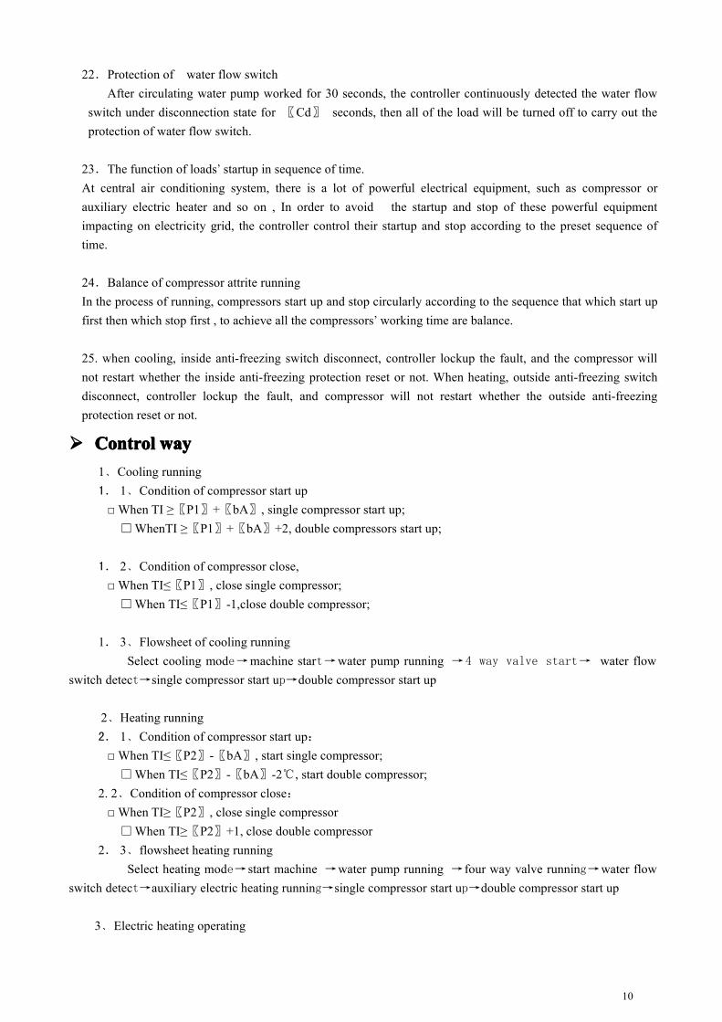
���� WiringWiringWiringWiring diagramdiagramdiagramdiagram ofofofof systemsystemsystemsystem
I02 I03 I11 I12 I41 I42 I43
A 02
A 03
A 11
A 21
link
age
cont
rol
insi
de w
ater
flo
w s
wit
ch
insi
de a
nti-
free
zing
sw
itch
high
pre
ssur
e sw
itch
1
low
pre
ssur
e sw
itch
1
outs
ide
wat
er f
low
sw
itch
outside return w ater tem p
outside outlet w ater tem p
inside outlet w ater tem p
inside return w ater tem p
environm ent tem p
insi
de w
ater
tem
p
outs
ide w
ater
tem
p
elec
tric
hea
ting
4-w
ay v
alve
com
pres
sor
1
zero
line
N
S
T
TR A N 2
w iring diagram
TR A N 1 N 002 011 021 022 031 041 042 043
A 31
A 01
I01
001
R (L)
TO LC D
LC Dcontrol panel
alar
m
fire
wir
e
5
5
135
95
com
pres
sor 2
outside anti-freezing sw itch
low
pre
ssur
e sw
itch
2
high
pre
ssur
e sw
itch
2
� Don’t install the LCD control panels outdoor, please separate the strong electricity and weakelectricity when wiring
14
I02 I03 I11 I12
A02
A03
A11
A21 outside return water temp
outside outlet water temp
inside outlet water temp
inside return water temp
environment tempS
T
LCDcontrol panel
outside anti-freezing switch
wiring diagram
connect compressorA B C N inside water
pumpearth outside water
pumpinside waterflow switch
outside waterflow switch
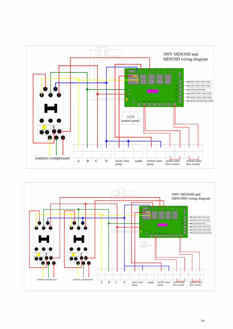
380V MDS30D andMDS50D wiring diagram
I02 I03 I11 I12
A02
A03
A11
A21 outside return water temp
outside outlet water temp
inside outlet water temp
inside return water temp
environment tempS
T
outside anti-freezing switch
wiring diagram
connect compressor2connect compressor1A B C N inside water
pumpearth outside water
pumpinside waterflow switch
outside waterflow switch
380V MDS60D andMDS100D wiring diagram

15
WARRANTYWARRANTYWARRANTYWARRANTYDear customers,
Thank you for using our products. We will supply you with complete after-services according to“SUN&DAY” and “New three guarantees of quality”. Please read our instruction for more detail before using, sothat you know how to install and use properly its excellent character of function. If you have any problems orsuggestions, please contact the local agent or appointed Repair Company. They will give you good answer andbetter service.
The meanwhile, Please send the certification that you cut away from warranty card to our company afteryou install the heat pump in two weeks. We will record it validly, and then your heat pump will get repairs foreverfrom the day when you brought it (Except the project machine which fix period is 1 year). During warranty periodwe can freely supply accessory. After that time you should pay for relevant material fee.
If there is problem, please write down the situation about problem & the No. of certification and informour company, then we will send person to repair it. But the follow situations are beyond our free repair program.
1. The forces of nature caused the problem. A>Flood, earth quake, typhoon, snowstorm, and thunder andlighting. B>Please clean up the inside, water around condenser when not using it When temperature isbelow zero 5C degree and there is no electricity. Make sure it is not damaged by ice.
2. Incorrect action. For example: Didn’t clean evaporator, lacking of water, not enough voltage and soon.
3. The problem caused by over use range. A>beyond the fixed temperature range, Using it when thevoltage is too high or too low. B>the machine works continuously over 12 hours period leading tocompressor damaged.
4. The problem caused by change circuit board or change accessory without permission5. The problem caused by repairs, if done by someone not certified by our company.6. The problem cause by incorrect installation. A> the mistake of mislead pipe B>the mistake of mislead
cable. C>Modified products without permission.
We reserve the right of the problem of the final releaseRepair recordDate Reason Repair company Memory