water systems precision water distillers owners’ · pdf fileprecision water distiller...
TRANSCRIPT

Part No. 097121- Series: 0013
Printed in Canada 06-24-2003
Copyright © 2003
Precision Water Distillers
Owners’ Guide
Model: PWS 8-5 Part No. 500002
Series: 0013
Manufactured By: Precision Design & Manufacturing Inc. 10331-105 Street, Westlock, AB, Canada T7P 2H7 http://www.precisioncanada.com e-mail: [email protected] Phone: (780) 349 4933 FAX: (780) 349 4957
PRECW ater System s
SION
Please read this Owners’ Guide completely before installing or operating your Precision Water Distiller.
Specifications are subject to change without notice.

2
This page left intentionally blank

3
TABLE OF CONTENTS.....................................................................................................................................................3
INTRODUCTION................................................................................................................................................................4
RECORDS......................................................................................................................................................................... 5
PRECISION WATER DISTILLER WARRANTY.................................................................................................................6
IMPORTANT SAFETY PRECAUTIONS ............................................................................................................................7
ADDITIONAL SAFETY RECOMMENDATIONS .........................................................................................................................7
PRECISION WATER DISTILLER OWNERS' SUMMARY.................................................................................................. 8
WATER DISTILLER FEATURES....................................................................................................................................... 9
10 FACTORS THAT WILL AFFECT YOU WATER DISTILLER PRODUCTION.............................................................. 10
UNDERSTANDING HOW PURE WATER IS PRODUCED .............................................................................................. 13
FINDING A GOOD INSTALLATION LOCATION............................................................................................................. 14
UNPACKING YOUR WATER DISTILLER ....................................................................................................................... 15
WATER DISTILLER INSTALLATION TOOLS................................................................................................................. 17
STORAGE TANK ASSEMBLY........................................................................................................................................ 18
MANUAL DRAIN VALVE TUBE INSTALLATION ........................................................................................................... 21
FEED WATER LINE CONNECTION................................................................................................................................ 22
BOILING TANK LID INSTALLATION.............................................................................................................................. 25
STORAGE TANK LID REMOVAL AND INSTALLATION ................................................................................................ 26
WATER DISTILLER WALL STABILIZER........................................................................................................................ 26
OPERATION.................................................................................................................................................................... 27
CONTROLS - POWER, FAN, WATER, OVERHEAT RESET AND FUSE .................................................................................... 27 STORAGE TANK DRAIN VALVE ........................................................................................................................................ 29 BEFORE INITIAL WATER DISTILLER OPERATION................................................................................................................ 30 NORMAL OPERATION...................................................................................................................................................... 31
MAINTENANCE AND CLEANING................................................................................................................................... 32
REGULAR INSPECTION AND CLEANING OF BOILING TANK.................................................................................................. 32 CLEANING THE BOILING TANK USING CLEANER DESCALER ............................................................................................... 33 REPLACING CHARCOAL IN CHARCOAL FILTER CANISTER .................................................................................................. 35 STERILIZATION ............................................................................................................................................................... 36
Liquid Sterilization of Storage Tank and Optional Pump Water Line System ..................................................... 36 Steam Sterilization of Water Distiller Head............................................................................................................ 37 Steam Sterilization of Water Distiller Head, Filter Canister and Storage Tank.................................................... 39 Maintenance Schedule Table.................................................................................................................................. 41 Owner Maintenance Record Table ......................................................................................................................... 41
TROUBLESHOOTING..................................................................................................................................................... 42
OPTIONAL ACCESSORIES............................................................................................................................................ 47
PWS APK-2 PUMP KIT .................................................................................................................................................. 47 PWS APK-2 PUMP KIT INSTALLATION ............................................................................................................................ 48 PWS AED-1 AUTOMATIC ELECTRIC DRAIN KIT INSTALLATION ......................................................................................... 53 ADDITIONAL OPTIONS..................................................................................................................................................... 57
Sediment Pre-Fitler Assembly, Charcoal Post-Filter Assembly, Pressure Accumulator, Water Distiller Cleaner and Descaler, Pure Activated Coconut Charcoal for Refillable Charcoal Filter Canisters and Tee Valve......... 57
SPECIFICATIONS AND TECHNICAL INFORMATION.................................................................................................... 59
WIRING LIST AND SCHEMATIC ......................................................................................................................................... 60
INDEX.............................................................................................................................................................................. 62
WARRANTY REGISTRATION CARD ............................................................................................................................. 63
Table of Contents

4
Introduction Congratulations on the purchase of the most advanced water distiller in the industry! When installed and maintained properly, your Precision Water Distiller will provide years of safe, trouble free service. It is important to observe and follow the safety and maintenance instructions carefully. If you have any questions or concerns regarding installation or operation of your water distiller, please contact your dealer. All 120 VAC Precision Water Distillers are certified to cCSAus Classes 2831-02 and 2831-82 under the Canadian and American Electrical Code. All water distillers are factory tested with a high voltage ‘Dielectric Strength Test’ and ground fault test prior to shipping. Precision Water Distillers have been tested by EnviroTest Laboratories which found the water distillation units to be very effective water treatment systems capable of removing both harmful pathogens and toxic chemicals from water. In their study all pathogens were eliminated and none were found in the distilled water. The water distillation system also effectively removed all of the soluble inorganic chemicals tested. Removal efficiencies of 99% or greater were achieved for almost every chemical tested. All Precision Water Distillers are operated and tested at the factory and have produced distilled water to make sure all components are functioning properly. All water distillers are wiped clean before shipping, but there may be a water ring inside the boiling tank. There may also be an off-colour line at the seams of the storage and boiler tank. This is caused by the TIG welding process used during manufacturing. This is normal and is not a sign of a problem. Follow all the Before Initial Water Distiller Operation procedures and you will have pure water in no time. Your Precision Water Distiller must be installed according to any Local, State or Provincial Regulations.

5
Records Please record all of the important information below to assist you and the service center in case there is any service work required in the future. All of the information is required to properly identify your water distiller and will make servicing much easier. The information is located on the serial plate on the side of the water distiller head. The Serial Plate Location Diagram below shows a sample serial plate.
Serial Plate Location Diagram
Model: PWS 8-5 Series: eg: 0013
Serial Number: eg: 0123012
Date of Purchase: ___________________________________________________ Dealer Purchased From: ____________________________________________
Optional Pump Serial No: __________________________________________
Series: __________________________________________ Optional Drain Serial No: __________________________________________ Series: __________________________________________

6
Precision Water Distiller Warranty - The warranty for your Precision Water Distiller covers defects in
materials for two (2) years on all parts and labor to the original purchaser.
- Stainless Steel parts are covered by a 15 year pro rated warranty.
This covers all stainless steel parts such as the boiling and storage tank. With this warranty it is the responsibility of the distiller owner to properly maintain the distiller. If there is any misuse or abuse the lifetime warranty will be void.
- Precision Water Systems does not warrant any transportation charges
incurred to complete the repair. The distiller owner is responsible for all shipping charges to and from the service center.
- Warranty is void if the distiller is found to have been consumer
damaged or misused, caused by acts of God, unauthorized alteration, repair or vandalism.

7
Important Safety Precautions When using electrical appliances, basic safety precautions should always be followed including the following:
1. Read all instructions. 2. Do not touch hot surfaces. Use handles or knobs. 3. To protect against electrical shock do not immerse cords or plugs in
water or other liquid. 4. Close supervision is necessary when any appliance is used near
children. 5. Do not allow children to operate this appliance. 6. Unplug from outlet when not is use and before cleaning. Allow to cool
before putting on or taking off parts. 7. Do not operate any appliance with a damaged cord or plug or after the
appliance malfunctions or has been damaged in any manner. Return appliance to the nearest service facility for examination, repair or adjustment.
8. The use of accessory attachments not recommended by the appliance manufacturer may cause injuries.
9. Do not use outdoors. 10. Do not let cord hang over edge of table counter, or touch hot surfaces. 11. Do not place on or near a hot gas or electric burner, or in a heated
oven. 12. Extreme caution must be used when moving an appliance containing
hot water. 13. Always attach plug to appliance first, then plug cord into the wall
outlet. To disconnect, turn any controls to “off”, then remove plug from wall outlet.
14. This appliance is intended for household use. 15. Save these instructions.
Additional Safety Recommendations
1. Always unplug appliance before servicing. 2. Do not use extension cords with appliance. 3. Ensure there is adequate air space around the appliance to allow the heat
from the appliance to be removed and supply adequate fresh air for cooling.

8
Precision Water Distiller Owners’ Summary
The following is a summary of the information contained in this Owners’ Guide and required to install and operate your Water
Distiller
1) Find a good location for installing your Water Distiller – See Finding a Good Installation Location.
2) Unpack the water distiller and parts - See Unpacking Your Water Distiller.
3) Assemble the Water Distiller – See Storage Tank Assembly Manual Drain Valve Tube Installation Feed Water Line Connection Boiling Tank Lid Installation Water Distiller Wall Stabilizer
4) Install all purchased Options - See Optional Accessories for installation instructions.
5) Steam sterilize boiling tank and storage tank – See Steam Sterilization in the Maintenance and Cleaning section.
6) Load Charcoal Filter Canister – See Replacing Charcoal in Charcoal Filter Canister in the Maintenance and Cleaning section.
7) Follow procedure in Normal Operation section. 8) Enjoy pure, distilled water!
9
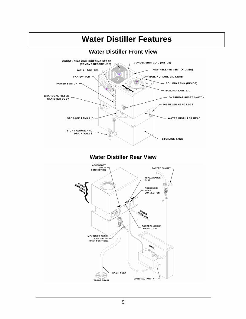
Water Distiller Front View
Water Distiller Rear View
Water Distiller Features
CONDENSING COIL (INSIDE)
GAS RELEASE VENT (HIDDEN)
BOILING TANK LID KNOB
BOILING TANK (INSIDE)
BOILING TANK LID
OVERHEAT RESET SWITCH
WATER DISTILLER HEAD
POWER SWITCH
FAN SWITCH
WATER SWITCH
CONDENSING COIL SHIPPING STRAP(REMOVE BEFORE USE)
CHARCOAL FILTERCANISTER BODY
STORAGE TANK LID
DISTILLER HEAD LEGS
STORAGE TANK
SIGHT GAUGE ANDDRAIN VALVE
PANTRY FAUCET
OPTIONAL PUMP KITFLOOR DRAIN
DRAIN TUBE
IMPURITIES DRAINBALL VALVE
(OPEN POSITION)
ACCESSORYPUMPCONNECTION
REPLACEABLEFUSE
CONTROL CABLECONNECTION
ACCESSORYDRAIN
CONNECTION

10
1. Water Volume Measurement
a) How are you measuring your water? The most accurate is by weight. 1 litre of pure water = 1 kg = 1000 g = 2.2046 lbs
b) Water distillers are rated in US gallons, NOT Imperial Gallons. 1 US Gallon = 3.785 litres = 3.785 kg = 8.344 lbs = 0.833 Imp. Gallons
c) Most distilled water holding tanks do not completely drain from the tap. Ensure this volume of water is included in your calculation by completely draining the tank or starting your production check with this volume pre- filled. 2. Line Voltage The line voltage at the outlet where the distiller is connected should be checked with a voltmeter. Line voltage is often much less than expected, especially in rural areas. Line voltage will also usually drop off dramatically when the daily commercial load hits the grid from approximately 8 am to 5 pm (often when the distiller owner is not home and unable to check the line voltage). Line voltage lower than the distiller rated voltage (on the serial plate) will drastically lower the water production. 3. Fill Water Temperature The water used to fill the machine may affect the water production. Cooler fill water will take more time/energy to heat to the boiling point than hot water. 4. Ambient Air Temperature Water distillers with cooling fans must have sufficient ventilation so that the boiled steam can be cooled and condensed into distilled water. Restriction of air flow (such as a closed cupboard) will result in a hot ambient air build up which will not allow all of the steam to condense into distilled water and some water production may escape as steam into the atmosphere through the charcoal filter or volatile gas release vent. This steam loss can also occur in hot summer periods or very warm climates.
10 Factors That Will Affect Your Water Distiller Production

11
5. Heating Element and Boiler Cleanliness As the water distiller removes impurities some of the impurities may cling to the boiler tank and the heating element. Any of this scale may build up around the heating element and actually insulate it, which will drastically decrease the thermal efficiency of the heating element and require more time/energy to boil water, which will decrease the water production. 6. Altitude The water distiller is rated at the altitude of the manufacturer, which is approximately 675 m (2214 ft) above sea level. Locations lower than this (closer to sea level) will have reduced water production due to the higher boiling point of water at higher atmospheric pressures at lower altitudes. 7. Operating Time, Warm-up Period & Suitable Storage When checking the water distiller production, the start time should be when the first few drops of water have entered the charcoal filter canister. Do not start timing when the distiller turns on as it takes a few minutes for the heating element, boiler tank and water to heat up. The distiller production rating does NOT account for this time, but rather the continuous production after the distiller is up to temperature. Ensure when checking production that you have suitable water storage for holding the amount of water that will be produced. 8. Manual Fill Boiling Tank Fill Level When checking the water distillation production on manual fill water distillers, the amount of water initially poured into the boiling tank will affect the production. Water should be filled to the water level pin so that once the water is hot the maximum amount of water can be distilled without having to heat up and refill. Under-filling the boiler will decrease the amount of water distilled. Again, the warm-up time should not be included in the production rate.

12
9. Boiling Tank Heating Element Once all other factors have been eliminated or checked, have an authorized service center check that the proper heating element has been installed in your distiller. Always replace heating elements with the manufacturers supplied heating elements. Other elements are available from hardware stores, home repair centers, etc. and look like the same element but they are almost always not the same. Even if the voltage and wattage are the same, they usually have different wattage densities and most likely different element sheath materials, which will result in premature heater burnout in continuous water distillation of raw water. These heating elements will also likely affect your water distillation capacity. 10. Combination of the above Factors. Often a reduced water distiller’s production is a combination of many or all of the above factors. To ensure maximum production from your water distiller, keep your water distiller clean and operate it in a well-ventilated area and use room temperature feed water where possible.

13
Your water distiller operates the same as Nature’s hydrological cycle. See the Hydrological Cycle Diagram below. Nature uses the heat of the sun to vaporize surface water and draw it into the atmosphere leaving the impurities behind. As the vapour cools it condenses and returns back to the earth as rain or snow. When rain or snow falls it passes through smog, dust and many other types of contaminants. These contaminants can be picked up by the falling rain or snow. Additional contamination of water can occur when it moves through the ground.
Hydrological Cycle Diagram Water Distillers complete their own hydrological cycle. The advantage of
a water distiller over Nature is that the water is produced in a closed environment free of pollution and contaminants.
Your water distiller uses the boiling tank to heat the feed water to create steam. The steam rises from the boiling tank leaving almost all of the impurities behind. The steam enters the condensing coil and is cooled by the fan. As the steam cools it condenses into pure distilled water and is stored in a stainless steel storage tank. The charcoal filter between the condensing coil and storage tank and the volatile gas vent remove any contaminants that boil at lower temperatures than the boiling point of water. The impurities from the process remain in the boiling tank and are drained to a suitable drain.
CONDENSATION
EVAPORATION
SMOG, DUST, ETC.
ROCK DEEP PERCOLATIONGROUND WATER
SURFACE WATER
PRECIPITATION
Understanding How Pure Water is Produced

14
Before installing your water distiller it is important to find a good location. Following the points listed below will provide the best location for your water distiller:
1. The water distiller must be plugged directly into a dedicated 120VAC, 15 Amp wall outlet.
2. The water distiller requires sufficient airflow around it to operate. The air is used to cool the water distiller condensing coil. Locate the water distiller in an area that will provide enough room for good air flow. Do not place the water distiller in an enclosed area like a closet.
3. When using the Automatic Feed Water Line Connection to the water distiller, locate the water distiller close to a household cold water line (after a water softener if available).
4. Locate the water distiller where a pail or suitable container can be used for the impurities drain. Close to a floor drain (sewer) is best especially if the Automatic Drain Kit is installed.
5. When unpacking the water distiller and options note the sizes and consider this when picking an installation location.
6. Locate the water distiller away from a bedroom or other area where the noise of the water distiller may be undesirable.
7. Locate the water distiller close to the kitchen faucet area if the automatic pump option is being used.
8. Locate the water distiller in an area that is clean and free of dust so the cooling coils remain clean when the fan is drawing fresh air.
Finding a Good Installation Location
15
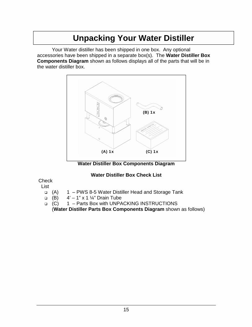
Your Water distiller has been shipped in one box. Any optional accessories have been shipped in a separate box(s). The Water Distiller Box Components Diagram shown as follows displays all of the parts that will be in the water distiller box.
Water Distiller Box Components Diagram
Water Distiller Box Check List
Check List
� (A) 1 – PWS 8-5 Water Distiller Head and Storage Tank � (B) 4’ – 1” x 1 ¼” Drain Tube � (C) 1 – Parts Box with UNPACKING INSTRUCTIONS
(Water Distiller Parts Box Components Diagram shown as follows)
(A) 1x
(B) 1x
(C) 1x
Unpacking Your Water Distiller

16
Water Distiller Parts Box Components Diagram
Water Distiller Parts Box Check List
Check List Part No.
� (A) 080043 1 – Sight Gauge and Valve, HT, 6” � (B) 080115 1 – Sample Descaler/Cleaner � (C) 080116 1 – Sample Coconut Charcoal � (D) 500306 1 – Stainless Steel Canister � (E) 036005 1 – Valve Kit, Self Piercing � (F) 500184 1 – Boiling Tank Lid � (G) 034014 1 – Stem, Plug, 3/8” JG � (H) 080121 1 – 1 ¼” Gear Clamp � (I) 052002 2’ – Sterilization Drip Tube � (J) 052000 16’– ¼” Feed Line � (K) 500282 1 – JG Removal Tool � (L) 097121 1 – PWS 8-5 Owners Guide
1. Remove all loose pieces from the water distiller box and save all
packaging until all the parts are identified and located. 2. Check inside boiler tank and storage tank for any parts that may be
shipped in that area. If any parts are missing or if you feel you have been given the wrong part, DO NOT return the water distiller unit. Contact your dealer for the required parts. They will be pleased to assist you.
3. Remove all protective plastic from water distiller head, storage tank, boiling tank lid and storage tank lid.
(L) 1x
(D) 1x(C) 1x(A) 1x
(G) 1x (H) 1x (K) 1x
(E) 1x(B) 1x
(J) 1x(I) 1x
(F) 1x
PWS WATER DISTILLER
PWS 8-5
OWNERS' GUIDE

17
Shipping Tie Removal Diagram
4. Refer to Shipping Tie Removal Diagram above. Cut/Remove the shipping tie located on the top of the water distiller head. Be careful not to scratch the water distiller when removing. This tie supports the cooling coil during shipping only.
(A) (B)
TOOLS REQUIRED: For Water Distiller Installation
(A) #2 Phillips screwdriver (B) Slotted screwdriver
Water Distiller Installation Tools
COIL SUPPORT TIE
WATER DISTILLER HEAD

18
1. Disconnect the Control Cable that is between the water distiller head and the storage tank by loosening the locking ring and unplugging. See the Control Cable Disconnect Diagram below.
Control Cable Disconnect Diagram
2. Remove the water distiller head from the storage tank by lifting the water distiller head straight up from the storage tank. See the Water Distiller Head Removal Diagram below.
Water Distiller Head Removal Diagram
Storage Tank Assembly
BULKHEAD, 3/8"JG(INSIDE DISTILLER)
TUBE, SS, 3/8" X 1-1/2"
CHARCOAL FILTERCANISTER BODY
FILTER CAP
CONTROL CABLE
WIRESBOX

19
3. Remove the sight gauge with valve from the parts box.
Sight Gauge Installation Diagram
4. Refer to Sight Gauge Installation Diagram above. Remove the plastic hex jam nut from the threaded body of the valve (leaving washer gasket on threads).
5. Remove the storage tank lid by holding down on the lid and turning the black knob counter clockwise while lifting, approximately five turns. Slide the lid to one side and turn the knob and lid together while tilting. This should allow the Tee Bar bracket under the lid to come out of the tank opening. Slide the lid out.
6. Push the gasket tightly up against the valve. 7. Insert the threaded valve end with gasket attached through the hole on
the front of the storage tank. 8. While holding the sight gauge with valve in the storage tank hole with one
hand, insert your other hand with the plastic hex jam nut through the storage tank lid opening.
9. Place the hex nut onto the threaded end of the valve. 10. Hand tighten the hex nut clockwise onto the valve.
3/8" JAM NUT
#10-24 MACHINE SCREWSTAINLESS STEEL
GASKETTHREADED FAUCET END
SIGHT GAUGE
DRAIN VALVE
VALVE HANDLE
STORAGE TANKSIGHT GAUGESUPPORT

20
Tightening Sight Gauge Nut Diagram
11. Refer to the Tightening Sight Gauge Nut Diagram above. To fully
tighten the nut, turn the valve counter-clockwise1/4 of a turn to the start position and ensure that the jam nut is still hand tight. Holding the jam nut, turn the valve clockwise until upright at the finish position.
12. Remove the #10-24 screw from the sight gauge support and install
through the inside of the storage tank using a Phillips screwdriver. Tighten until snug only.
13. Make sure the storage tank is free from any dust or material and replace the storage tank lid.
14. Check for leaks when storage tank begins filling.
NOTE: The sight glass is fragile, do not push on the gauge (push on bottom near threaded area).

1. Refbelusinfloo
NOTEPWS guide
Manual Drain Valve Tube Installation
21
er to the Manual Drain Valve Tube Installation Diagram shown ow. Push the drain tube onto the elbow and secure with gear clamp g a slotted screwdriver. Run the drain tube to a container or suitable r drain like the sewer.
Manual Drain Valve Tube Installation Diagram
: If you have purchased the Automatic Electric Drain Kit, Go to the AED-1 Automatic Electric Drain Kit Installation section of the and install it now.
TUBETO SEWER
GEAR CLAMP (SHIPPED IN PARTS BOX)
BACK OF THEDISTILLER
BALL VALVE ASSEMBLY

Feed Water Line Connection
(A) (C) (D)
1/2" OR
(B) (E) (F)
TOOLS REQUIRED: For Feed Water Line Connection
(A) Slotted Screwdriver (B) Drill with 1/8” drill bit (For
Steel or Brass Water Line)(C) ½” Open End Wrench or (D) Pliers (E) JG Removal Tool (supplied
in Parts Box) (F) Utility Knife
1. Select a household water line to supply the water distiller with feed water.
Be sure to use a cold water line and pick a suitable location closest to the water distiller location.
NOTE: If you have a water softener be sure to connect the water distiller feed line on the outlet side of the softener as soft water will reduce cleaning and maintaining of the water distiller. Using a water supply from the outlet of a hot water heater is not recommended as some of the internal components of the water distiller are not designed to be used with water temperatures above normal cold household water supply. Scale andsediment from hot water tanks can also cause problems by plugging the water distiller raw water plumbing components.
22
Feed Water Line Installation Diagram
1/4" WATER FEEDLINE
ELBOW
COLLET
LOCKING CLIP
BOLTSSADDLE VALVE COMPRESSIONNUT
INSERT
FERRULE
RUBBERSEAL
LOWER CLAMP
NUTSCOPPER TUBE-NO DRILLING*STEEL TUBE-DRILL 1/8"Ø*BRASS TUBE-DRILL 1/8"Ø*SHUT OFF WATER SUPPLY
WATER SUPPLY TUBE

23
2. Refer to the Feed Water Line Installation Diagram above. Install the self-piercing valve kit onto the household water feed line with a slotted screwdriver. Detailed instructions for installing the valve are listed below.
3. Attach the ¼” water line to the self piercing valve with a ferrule, insert and compression nut using a ½” open end wrench or pliers. Route the ¼” tubing to the inlet on the back of the water distiller head. Cut approximately one foot longer than needed with suitable water line routing.
4. Remove the existing piece of ¼” tubing from the elbow (installed for shipping purposes only) on the bottom rear of the water distiller head using a slotted screwdriver or JG removal tool to remove the locking clip on the elbow. Push in on the dark grey collet with the JG removal tool and pull out the piece of ¼” tubing.
Instructions: For Copper and Plastic Water Line:
NO DRILLING OR WATER SHUT– OFF REQUIRED. Caution: Be sure piercing pin is completely backed up into valve
body by turning handle counter-clockwise. 1. Loosely assemble one side of top clamp to bottom clamp with screw
and nut provided. 2. Be sure rubber gasket is in place over piercing needle and position
valve assembly on copper or plastic water line. 3. Assemble other side of top clamp to bottom clamp with remaining
screw and nut and tighten both pieces with a slotted screwdriver until valve assembly is firmly attached to water line.
4. Complete compression connection to valve outlet. 5. Turn valve handle clockwise to pierce the supply line and close the
valve. 6. Open valve by turning handle counter-clockwise to desired water
flow rate. For Steel and Brass Water Line:
1. Turn off the household water supply. 2. Drill a 1/8” hole at the bottom of the steel or brass water line that will
be used for the water distiller water feed line. 3. Loosely assemble one side of top clamp to bottom clamp with screw
and nut provided. 4. Be sure the piercing pin is turned into the valve body. Place the
rubber gasket over the piercing needle and position needle into drilled 1/8” hole.
5. Assemble other side of top clamp and bottom clamp with remaining screw and nut and tighten both pieces with a slotted screwdriver until valve assembly is firmly attached to the water line.
6. Complete compression connection to valve outlet. 7. Turn on household water supply. 8. Open flow rate by turning saddle valve handle counter-clockwise to
desired flow rate.

24
5. Push the ¼” household feed line fully into the elbow and reinstall the locking clip between the elbow and collet.
6. Make sure the Control Cable is connected between the water distiller head and the storage tank by turning the plug until the splines lock and then turn the locking ring until finger tight. See the Control Cable Connection Diagram below.
Control Cable Connection Diagram
Boiling Tank Drain Valve Diagram
7. Refer to the Boiling Tank Drain Valve Diagram above. Close the boiling tank drain ball valve at the rear of the water distiller (ball valve is shown in the closed position). If the water distiller is equipped with the PWS AED-1 Automatic Electric Drain the ball valve should be in the open position.
8. Tighten the saddle valve handle completely by turning clockwise to pierce the water supply line (copper or plastic water line only). Open the water supply to the water distiller by turning the saddle valve handle counter-clockwise. Check for leaks.
TO SEWER
DRAIN ELBOW ASSEMBLY
GEAR CLAMP
TUBE
CONTROL CABLE
WIRESBOX
25
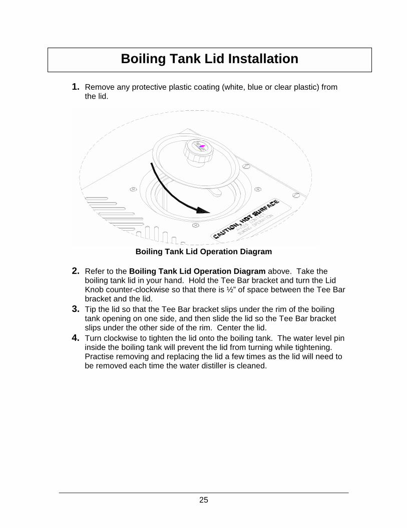
1. Remove any protective plastic coating (white, blue or clear plastic) from
the lid.
Boiling Tank Lid Operation Diagram
2. Refer to the Boiling Tank Lid Operation Diagram above. Take the boiling tank lid in your hand. Hold the Tee Bar bracket and turn the Lid Knob counter-clockwise so that there is ½” of space between the Tee Bar bracket and the lid.
3. Tip the lid so that the Tee Bar bracket slips under the rim of the boiling tank opening on one side, and then slide the lid so the Tee Bar bracket slips under the other side of the rim. Center the lid.
4. Turn clockwise to tighten the lid onto the boiling tank. The water level pin inside the boiling tank will prevent the lid from turning while tightening. Practise removing and replacing the lid a few times as the lid will need to be removed each time the water distiller is cleaned.
Boiling Tank Lid Installation

26
1. To remove the storage tank lid, turn the Lid Knob counter-clockwise while lifting. Lifting while turning holds the Tee Bar bracket under the lid and allows you to loosen the lid. Continue turning and lifting until there is ½” of space between the Tee Bar bracket and the lid.
2. Tip the lid so that the Tee Bar bracket slips out from under the rim of the storage tank opening on one side, and then slide the lid so the Tee Bar bracket slips out from under the other side of the rim.
3. To replace the storage tank lid, tip the lid so that the Tee Bar bracket slips under the rim of the storage tank opening on one side, and then slide the lid so the Tee Bar bracket slips under the other side of the rim. Center the lid.
4. While lifting up on the storage tank lid knob, turn clockwise to tighten the lid onto the storage tank. Tighten until snug only.
Storage Tank Lid Removal and Installation

Con
(A)
R1 Amp There a(C) on tthe wat
Operation
NOTE: Read all parts of the Owners Guide before operating the water distiller. Follow the Before Initial Water Distiller Operationsteps and be sure to complete a Steam Sterilization of the Water Distiller Head, Filter Canister and Storage tank before distilling water for household use for the first time or after a period of storage or non-use.27
trols
(B) (C)
Operation Switches Diagram
efer to the Operation Switches Diagram above. There is a replaceable Slow Blow 240V fuse (A) on the bottom rear of the water distiller head. re three grey control switches (B) and one overheat manual reset switch he front of the water distiller head that allow you to control all functions of er distiller
OFF
PO
WE
R O
N I
ND
ICA
TO
R L
IGH
TS WATER FILLING
INDICATOR LIGHT
COOLING FANINDICATOR LIGHT
HEATING ELEMENTINDICATOR LIGHT

Power – ON/OFF
Fan – ON/OFF
Water – ON/OFF
NOTE: A clicking sound may be heard if the Water distiller is plugged into the wall electrical outlet, the power and water switches are in the ‘ON’ position and the boiler is empty. The clicking sound is the internal water solenoid valve activating.
- -
-
-
- Re- No
Co- To
swwa
- Bowh
- Tuop
- -
-
-
-
(ON
PO
SIT
ION
)P
OW
ER
(ON
PO
SIT
ION
)FA
NW
AT
ER
(ON
PO
SIT
ION
)
White indicator light. Normally ON when water distiller is operating with automatic feed water supply line. Will automatically fillthe boiler tank from the water supply line. Top square indicator light is illuminated whenever the switch is on. It will remain illuminated even when the water distiller is not operating. Bottom rectangular indicator light is illuminated only when the water is entering the boiling tank. The boiler will fill with water until the upper boiler water level is achieved.d indicator light. rmally ON when water distiller is operating. ntrols power to the entire water distiller. p square indicator light is illuminated whenever theitch is on. It will remain illuminated even when the ter distiller is not operating. ttom rectangular indicator light is illuminated only en the heating element in the boiler is on. rn power switch to OFF to stop Water distiller eration.
Amber indicator light. Normally ON when water distiller is operating. Controls power to the cooling coil fan. Top square indicator light is illuminated whenever the switch is on. It will remain illuminated even when the water distiller is not operating. Bottom rectangular indicator light is illuminated only when the fan is on. Fan should be running if the waterdistiller is distilling water. Turn Fan Switch to OFF only when performing a steam sterilization of the water distiller.
28

Overheat Reset Switch – Manual Reset
Fuse – 1 Amp Slow Blow 240V
Storage T
- Recessed into the front of the water distiller head front cover.
- The reset button will shut the unit off if the water distiller has overheated, it may be reset once the waterdistiller has cooled off. If the situation continually repeats itself this may also indicate a problem and should be looked at by a service center.
- The reset button is a safety feature and is designed to shut the water distiller down should it overheat.
- Push your finger through the hole in the front cover labelled ‘Manual Reset’ to reset. A snap will be heard when the switch is reset and distilling can resume.
- Th cirdis
- Alw
STORAGE TANK
SIGHT GAUGE ANDDRAIN VALVE
is is a feature to protect the pump option electricalcuit and is located on the bottom of the water tiller head at the rear. ays replace with the proper fuse.
29
ank Drain Valve To enjoy pure water from your water distiller storage tank use the storage tank drain valve on the front of the storage tank. The valve handle can be tipped one way to control the flow of water or tipped over the opposite direction and locked in the open position to fill large containers. Water can be pumped automatically to a faucet at the kitchen sink or other location by installation of an Optional Pump Kit. See PWS APK-2 Pump Kit and PWS APK-2 Pump Kit Installation in the Optional Accessories Section for a diagram of the kit and installation instructions.

30
1. Ensure the boiling and storage tank lids are in place and tight. 2. Make sure all control switches are turned off. (See Operation-Controls
Section if not sure how to operate). 3. Ensure the water supply saddle valve is turned fully on by turning counter-
clockwise from tight.
Boiling Tank Water Gauge Pin Diagram
4. Plug Water distiller into a wall outlet. 5. Turn Power, Fan and Water switches ON (Do not turn Water switch on if
filling manually). 6. Water should be entering the boiling tank. Remove the boiling tank lid to
check. Replace lid if water is entering. The fan and heater should turn on as soon as the water level is above the heating element.
7. Check for leaks around the saddle valve and supply pipe and around the water solenoid on the water distiller head. See Water Solenoid Valve in Water Distiller Head Diagram below.
Water Solenoid Valve in Water Distiller Head Diagram 8. If there are no leaks and the water distiller is operating as described
above, shut all control switches off and perform steam sterilization on the water distiller head, filter canister and storage tank as described in the Maintenance and Cleaning section.
NOTE: Manual Fill Operation (If a pressurized water supply is not available such as using the water distiller at a cottage or on vacation) – Fill the boiler tank by removing the boiler tank lid and pouring water into boiler tank up to bottom of the water level pin. Refer to Boiling Tank Water Gauge Pin Diagram.
Before Initial Water Distiller Operation
WATERGAUGE
PIN
DRAIN STRAINER ATTACHEDTO THE DRAIN HOLE
WATER LEVEL
INSIDE BOILERDRAIN
STRAINER
IMPURITIESDRAIN OUTLET
SOLENOID VALVE(HIDDEN)
LOCKINGCLIPSADDLE VALVE
COLD WATERSUPPLY LINE
WATER FEEDLINE
ELBOW
COLLET
31
1. Ensure boiling and storage tank lids are in place and tight. 2. Ensure all electrical plugs are properly connected and the water supply
valve is turned on. 3. Turn the Power, Fan and Water switches to the ON position. Water will
enter the boiling tank, the heating element will energize and the cooling fan will start.
4. The water distiller will continue operating and distilling water until the storage tank is full. At this time the water distiller will turn off until the storage tank is drained to approximately 2/3 full and then the automatic water distiller will start producing distilled water again.
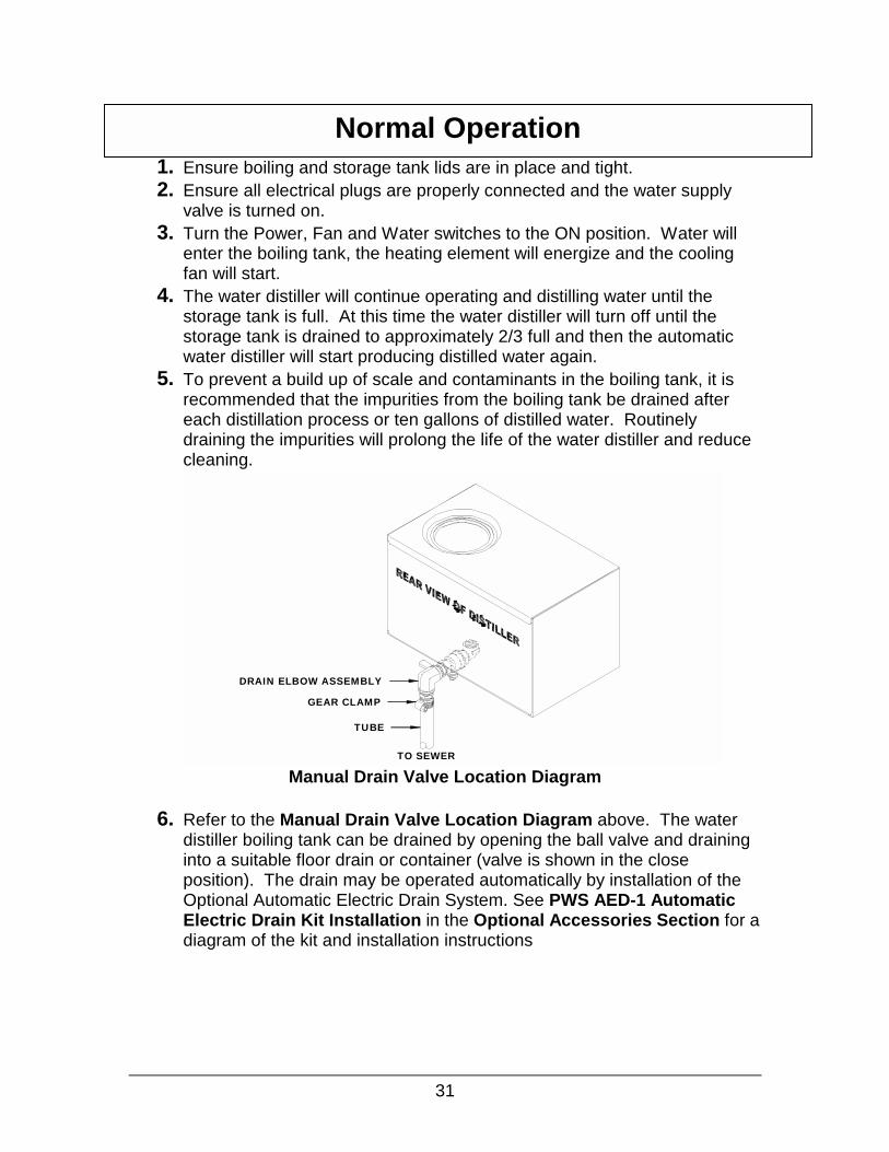
5. To prevent a build up of scale and contaminants in the boiling tank, it is recommended that the impurities from the boiling tank be drained after each distillation process or ten gallons of distilled water. Routinely draining the impurities will prolong the life of the water distiller and reduce cleaning.
Manual Drain Valve Location Diagram
6. Refer to the Manual Drain Valve Location Diagram above. The water distiller boiling tank can be drained by opening the ball valve and draining into a suitable floor drain or container (valve is shown in the close position). The drain may be operated automatically by installation of the Optional Automatic Electric Drain System. See PWS AED-1 Automatic Electric Drain Kit Installation in the Optional Accessories Section for a diagram of the kit and installation instructions
Normal Operation
TO SEWER
DRAIN ELBOW ASSEMBLY
GEAR CLAMP
TUBE
32
Introduction The purpose of purchasing a water distiller is so you will not have to drink the impurities in your drinking water. A water distiller effectively removes the impurities and chemicals from your water and returns the taste of pure water so that it is pleasing and healthy to drink for the entire family.
It is important to also keep the water distiller clean so that it can perform properly and efficiently. Regular cleaning and maintenance will allow the water distiller to continually provide pure water for a very long time. Regular Inspection and Cleaning of the Boiling Tank
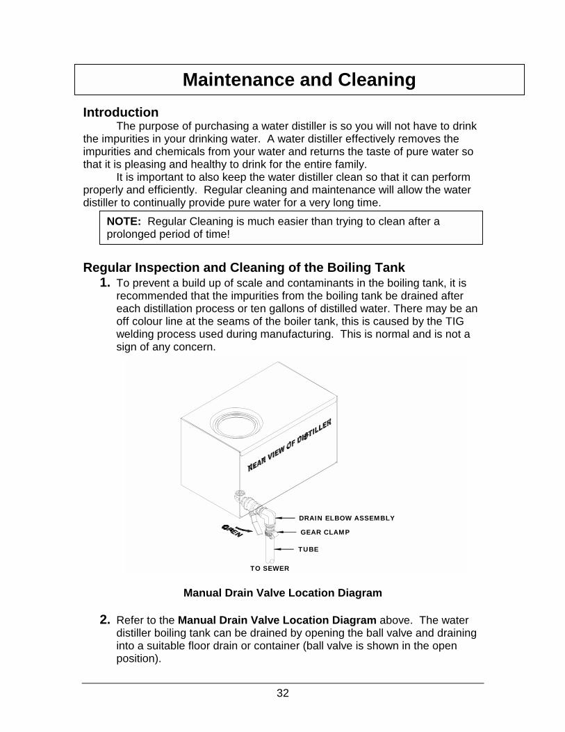
1. To prevent a build up of scale and contaminants in the boiling tank, it is recommended that the impurities from the boiling tank be drained after each distillation process or ten gallons of distilled water. There may be an off colour line at the seams of the boiler tank, this is caused by the TIG welding process used during manufacturing. This is normal and is not a sign of any concern.
Manual Drain Valve Location Diagram
2. Refer to the Manual Drain Valve Location Diagram above. The water
distiller boiling tank can be drained by opening the ball valve and draining into a suitable floor drain or container (ball valve is shown in the open position).
Maintenance and Cleaning
NOTE: Regular Cleaning is much easier than trying to clean after a prolonged period of time!
TO SEWER
DRAIN ELBOW ASSEMBLY
GEAR CLAMP
TUBE

33
3. The drain may be operated automatically by installation of the Optional Automatic Electric Drain System. See PWS AED-1 Automatic Electric Drain Kit Installation in the Optional Accessories Section for a diagram of the kit and installation instructions.
4. With the manual drain valve or the Automatic Electric Drain it is important to develop a regular maintenance routine. Every two weeks or 50 gallons of distilled water take a look inside the boiling tank when the water distiller is cool.
5. Check for scale build up on the walls of the boiler tank and the heating element. The heating element is the most critical. If there is 1/8” of build up or more on the heating element, then it is time to clean the boiling tank using the descaler cleaner. This process is described in the next section.
6. After checking the boiling tank every two weeks for about three months, you will be able to set up your own schedule as to how often the boiling tank needs to be cleaned with the descaler cleaner. Distilled water quantity use and raw water quality will determine your schedule.
Cleaning the Boiling Tank using the Cleaner Descaler
1. Turn all switches off and allow the water distiller to cool down. 2. If the water distiller is equipped with an Automatic Electric Drain, close the
ball valve behind the water distiller head. 3. Remove any loose scale from inside the boiling tank by hand through the
boiler lid. Remove the drain strainer and inspect for sediment or plugged holes. Clean if necessary. See the Boiling Tank Strainer Removal Diagram below to see how to remove the strainer.
Boiling Tank Strainer Removal Diagram 4. Remove the filter canister and place the sterilization tube onto the coil tube
to by-pass the storage tank. See Steam Sterilization of Water Distiller Head in this Maintenance and Cleaning section for more details.
DRAIN STRAINER
IMPURITIESDRAIN OUTLET
DRAIN STRAINER DETACHEDFROM THE DRAIN HOLE

5. Add 3 tablespoons of descaler cleaner to the boiling tank.
678
9
1 11 1 1 1
CAUTION: Descaler is a corrosive and poisonous substance. Read safety precautions on the package. As the initial water is added to the descaler in the boiling tank it will produce a bubbling foam substance. Do not overfill the boiling tank. Always leave boiling tank lid off when ever theboiling tank is being descaled to reduce fumes travelling through the cooling coil. Dispose of the first gallon of distilled water as a precaution.
34
. Fill the boiling tank half full with hot tap water.
. Mix the cleaning solution well to dissolve the descaler in the water.
. Fill up the remaining portion of the boiling tank with hot tap water to the bottom of the water gauge pin. See Boiling Tank Water Gauge Pin Diagram below.
Boiling Tank Water Gauge Pin Diagram
. Let the solution stand overnight. Leave the boiling tank lid off during cleaning to prevent descaler fumes from entering the cooling coil.
0.The next morning or when the mineral content is soft, drain the boiling tank using the ball valve. Remove any remaining loose scale by hand using rubber gloves.
1.Repeat cleaning if necessary. 2.Once all the scale has been removed, rinse the boiling tank several times
with warm tap water and remove any large pieces of scale by hand. 3.Replace the drain strainer. The strainer stops large impurities from
plugging the ball drain valve or Automatic Electric Drain valve. 4.Replace the boiling tank lid and complete steam sterilization process on
the boiling tank. See Steam Sterilization in this Maintenance and Cleaning Section. Reinstall the filter canister.
5.The boiling tank is now clean and ready to produce pure water again.
WATERGAUGE
PIN
DRAIN STRAINER ATTACHEDTO THE DRAIN HOLE
WATER LEVEL
INSIDE BOILERDRAIN
STRAINER
IMPURITIESDRAIN OUTLET

Replacing Charcoal in Charcoal Filter Canister
1
2
3
4
56
NOTE: Replace charcoal in filter every 2 months or every 500 gallons ofdistilled water.35
. Turn all switches off and allow the water distiller to cool down.
Charcoal Replacement Diagram
. Refer to the Charcoal Replacement Diagram above. Remove the complete charcoal filter canister by lifting the front corner of the water distiller head.
. Over a sink or suitable garbage can, remove the lid of the filter completely and empty charcoal from canister and rinse.
. Fill canister 2/3 full with new charcoal and rinse over a sink or pail with approximately 2 cups of distilled water until water runs clear.
. Press the filter cap back on to the filter canister.
. Lift the corner of water distiller head and slide the filter into the storage tank and lower the water distiller head so the 3/8” tube enters the top of the filter.
BULKHEAD, 3/8"JG(INSIDE DISTILLER)
TUBE, SS, 3/8" X 1-1/2"
FILTER CAP
CHARCOAL FILTERCANISTER BODY
Introduction:
Steam Sterilization should be performed on the water distiller boiler, filter canister and storage tank before the water distiller is used for the first time or after a period of storage or non-use. After initial sterilization, the boiler should be steam sterilized after any maintenance is performed and/or cleaning including the descaling process. The storage tank requires cleaning and steam sterilization after any maintenance, or if there are any problems with the quality of the distilled water.
If there is a water quality concern and the system may be contaminated, it is important to first remove the source of contamination and remove all contaminated debris and then complete a Liquid Sterilization before a Steam Sterilization.
Liquid Sterilization of Storage Tank and Optional Pump Water Line System
1. It important to first remove the source of contamination and remove all contaminated debris before liquid sterilization.
2. Drain the water distiller and water lines as much as possible.
3
4
5
6
7
NOTE: This is performed whenever it is suspected that the water distiller head, storage tank or pump water line system are contaminated.
Sterilization
NOTE: Liquid Sterilization Solutions can be made from Household bleach. The bleach should be diluted to 100-200 PPM. Products such as Javex, have 6% Sodium Hypochlorite and should diluted by placing 3 teaspoons per gallon of water. Always use Chlorine bleach that does not contain any other ingredients. Alternatively, Hydrogen Peroxide solutions may be usedby placing 3 teaspoons per gallon of water.
36
. Add 2 gallons of Liquid Sterilizing solution to the water distiller storage tank. If desired, spray some of the solution throughout the inside of the storage tank. You may need more sterilization solution if you are using more that 25 feet of pump water line.
. Run the pump by opening the faucet at the kitchen sink to put sterilizing solution through all water lines and dispensers. All the lines will be full of sterilization solution when you can smell the solution at the faucet. Wait 20 minutes.
. Rinse the entire inside of the storage tank with at least 2 gallons of distilled water. Run the pump to clear the lines of the sterilizing solution.
. Repeat the flushing of the storage tank with distilled water 2-3 times, rinsing the pump and all water lines at the same time. Continue until no chlorine smell is coming from the faucet.
. Complete a Steam Sterilization of the boiling and storage tanks.

37
1. Make sure the water distiller is cool before starting.
Water Distiller Head Steam Sterilization Diagram
2. Refer to the Water Distiller Head Steam Sterilization Diagram
above. Lift the front corner of the water distiller head. 3. Remove the charcoal filter. 4. Install the sterilization tube. Place the sterilization tube on the 3/8”
stainless steel filter inlet tube on the bottom of the water distiller head.
5. Place the other end of the steam sterilization tube into a container as it will drip water and steam.
Steam Sterilization of Water Distiller Head
NOTE: If Water Distiller is filled manually, fill the boiling tank with water to the bottom of the water gauge pin.
STERILIZATION TUBE
BULKHEAD,3/8"JG
BULKHEAD,3/8"(INSIDE DISTILLER)
3/8OD X 1-1/2"SS TUBE

38
6. If you are completing the steam sterilization for the first time, plug
the water distiller into a dedicated wall outlet.
Steam Sterilization Operation Switches Diagram
7. Refer to Steam Sterilization Operation Switches Diagram
above. Turn only the power and water switches ON. Leave the fan switch OFF. As the water distiller continues to heat up, it will sterilize the water distiller with steam by allowing pure steam to travel out of the cooling coil. Water and steam will drip from the sterilization tube. Caution: The Water Distiller is extremely hot during sterilization.
8. Leave the water distiller on for 1 hour. 9. After sterilization cycle is complete. Turn the fan switch ON and
allow any water in the cooling coil to drain. Leave the water distiller running with the fan on for about 15 minutes.
10. The water distiller will be very hot so turn all switches OFF (power, water, fan) and let the water distiller cool down for approximately 1 hour.
11. Remove the sterilization drip tube by pulling the plastic tube off the stainless steel charcoal filter inlet tube (keep the sterilization tube for future sterilizations).
12. Replace the charcoal in the charcoal filter canister. See Replacing Charcoal in Charcoal Filter Canister in this Maintenance and Cleaning Section.
13. The water distiller head is sterilized and ready for operation.

39
1. Make sure the water distiller is cool before starting.
Water Distiller Head, Filter Canister and Storage Tank Steam Sterilization Diagram
2. Refer to the Water Distiller Head, Filter Canister and Storage Tank
Steam Sterilization Diagram above. Lift the front corner of the water distiller head.
3. Remove the charcoal filter canister. Remove all charcoal and rinse until clean. Replace empty filter canister between water distiller head and storage tank
4. Place a container under the front storage tank sight gauge valve and leave the valve in the open position.
Steam Sterilization of Water Distiller Head, Filter Canister and Storage Tank
NOTE: If Water Distiller is filled manually, fill the boiling tank with water to the bottom of the water gauge pin.
BULKHEAD, 3/8"JG(INSIDE DISTILLER)
TUBE, SS, 3/8" X 1-1/2"
FILTER CAP
CHARCOAL FILTERCANISTER BODY

40
Steam Sterilization Operation Switches Diagram
5. Refer to Steam Sterilization Operation Switches Diagram above. Turn only the power and water switches ON. Leave the fan switch OFF. As the water distiller continues to heat up, it will sterilize the water distiller head, filter canister and storage tank with steam by allowing pure steam to travel out of the cooling coil. Water and steam will drip from the storage tank valve. Caution: The Water Distiller is extremely hot during sterilization.
6. Leave the water distiller on for 1 hour. 7. After sterilization cycle is complete. Turn the fan switch ON and allow any
water in the cooling coil to drain. Leave the water distiller running with the fan on for about 15 minutes.
8. The water distiller will be very hot so turn all switches OFF (power, water, fan) and let the water distiller cool down for approximately 1 hour.
9. After cooling down, the water distiller may need to be tipped or rocked forward and back to remove all the water from the storage tank.
10.Close the storage tank sight gauge valve. 11.Replace the charcoal in the charcoal filter canister. See Replacing Charcoal in Charcoal Filter Canister in this Maintenance and Cleaning Section. 12.The water distiller head, filter canister and storage tank are sterilized and ready for operation.

41
Maintenance Schedule Table Initially Weekly Monthly Semi-
AnnuallyAnnually As
Needed1) Check Scale Build Up. X X 2) Change Charcoal in Charcoal Filter Canister.
X X X 3) Clean Boiling Tank using Cleaner Descaler.
X X 4) Steam Sterilization of Boiling Tank after cleaning.
X 5) Steam Sterilization of Boiler and Storage Tanks.
X X
Owner Maintenance Record Table Change Charcoal
in Charcoal Filter Canister
Clean Boiling Tank using Cleaner Descaler
Steam Sterilization of Boiling Tank
Steam Sterilization of Boiling and Storage Tanks
Date Jan 21/03
Completed By BDR
Date
Completed By
Date
Completed By
Date
Completed By
Date
Completed By

42
PROBLEM CAUSE A) Water distiller does not operate.
1. Water distiller is not plugged in securely to the wall outlet or the circuit breaker is off.
2. Power switch on the water distiller is turned off 3. Reset button has shut the unit off. The reset
button will shut the unit off if the water distiller has overheated, it may be reset once the water distiller is cooled off. This may also indicate a problem and should be looked at by a service center. The reset button is a safety feature and is designed to shut the water distiller down should it overheat. Push your finger through the hole in the front cover labelled ‘Manual Reset’ to reset.
4. Reset button is faulty and needs to be replaced. Call Service Center.
5. The Storage tank is full of water. The storage tank water level must be lowered below 2/3 before the water distiller will operate.
6. Saddle valve is turned off. Turn it on. B) Water is coming out from the top of the charcoal filter.
1. Charcoal is old and compacted. Replace coconut charcoal. See Maintenance section-Replacing Charcoal in Charcoal Filter Canister.
2. Water solenoid valve has malfunctioned and is stuck open allowing water to flow from the boiling tank to the storage tank before it is distilled. Call Service Center.
3. The boiler fill micro switch requires adjustment or is faulty and needs to be replaced. The boiler tank overfills and flows into the charcoal filter. Call Service Center.
4. Check to see that boiler tank water level float is floating. If it is not floating properly this could be the problem. Call Service Center.
5. Charcoal filter is more than 2/3 full. There must be an air gap between the charcoal and the top of the filter. Remove Charcoal filter and make sure charcoal filter is only 2/3 full.
Troubleshooting Caution! Always Disconnect Water Distiller Electrical plug and Let the
Water Distiller cool down completely before completing any Troubleshooting.

43
PROBLEM CAUSE C) Steam or water is escaping from the top of the cooling coil.
1. The cooling coil is equipped with a gas release vent, a very small hole in the top of the coil. This is to release certain volatile gases. Steam may escape from this hole. This is normal.
2. If little or no water is being produced the cooling coil may have become disconnected from the boiling tank. Call Service Center.
D) Charcoal Filter is very hot and steam is escaping from the filter.
1. The fan switch is turned off. Check Switch. 2. Fan motor is not running properly, may be
defective, or the fan motor switch may be defective. Call Service Center.
3. Cooling coil fins are plugged with dust, dirt, or grease. Remove and clean or take to a service center for maintenance.
4. The location of the water distiller does not provide enough airflow for good cooling. Move the water distiller to an area with more air movement.
E) Boiling tank will not fill with water.
1. The self-piercing saddle valve is turned off. Check and turn on if necessary.
2. The direct water feed line may be obstructed or kinked. Check and fix.
3. The water switch and/or the power switch are off. Check switches.
4. The float in the boiling tank may be stuck. Check by opening boiler tank and lifting gently up on ball float.
5. Opening for water feed line inside the boiling tank may be scaled up. Check by opening boiler tank and checking scale build up.
6. Manual reset button has tripped. See A) 3. above.
7. Storage tank is over 2/3 full. Normal Operation. 8. Water Fill Micro Switch Faulty. Call Service
Center. 9. Solenoid valve is faulty. Call Service Center.
F) Water distiller may start to boil, then shuts off. It may restart after cooling down. Very small amount of water is produced.
1. Faulty Reset button. After letting water distiller cool down and trying to reset several times, call Service Center.
44
PROBLEM CAUSE G) Water distiller runs properly but little or no water is produced.
1. Improper Heating Element is installed or Heating Element is faulty. Call Service Center.
2. Auto drain valve is partially stuck open due to scale build up in the valve. Check valve and/or flush by pouring water through the top of the boiler tank opening.
3. Auto drain valve is open because it is not plugged into the water distiller head. Check and re-connect.
4. Boiler tank lid is loose. Check by moving Boiler Tank Lid Knob.
5. Reset button may be defective or weak. See A) 3 above.
6. Water supply may be restricted. Turn off saddle valve. Remove Feed Water line from back of water distiller. Place Feed Water line into a pail, turn on saddle valve and check water flow.
H) Strange taste in Distilled Water.
1. Boiling tank and/or storage tank may require cleaning. See maintenance section on cleaning water distiller.
2. Boiling tank has over filled, float system or water solenoid has failed and allowed un-distilled water to overflow into the cooling coil. Open boiler tank and check float operation.
3. Charcoal filter requires new Coconut Charcoal. 4. Auto-Drain has malfunctioned. Check boiling
tank for scale build up. See maintenance section.
5. Distilled water line may need cleaning. See maintenance section.
I) Fan does not operate automatically.
1. Fan switch is in OFF position. Check Switch. 2. Fan motor may be defective. Call Service
Center. 3. Storage tank is full and the water distiller has
shut it self off until the storage tank is only 2/3 full.

45
PROBLEM CAUSE J) With the Pump Option, there is no water at the faucet.
1. Pump plug on the water distiller head is loose. Check plug at rear of water distiller head.
2. Storage tank is empty. Water distiller has quit. See A) above.
3. There is no power to the pump. Check to make sure the pump is plugged into the water distiller head. Check to make sure there is power at the wall outlet.
4. Fuse on the water distiller head needs replacing.5. Pump motor failure. Call Service Center. 6. Kinked water line between the pump and the
faucet. Check water line for kinks. 7. Bottom float in the storage tank is stuck or faulty.
Open water distiller storage tank and check level sensor. Call Service Center.
K) With Pump Option, pump starts and stops without drawing any water
1. Small leak in the water line or faucet. Check water line for leaks.
2. Loose fittings on pump or lines. Check fittings for leaks-with proper wrench. See Pump Kit Installation Section.
3. Check-valve in pump may be stuck open. Call service center.
L) Water distiller does not operate and storage tank is empty.
1. Storage tank level sensor assembly is faulty. Open storage tank and check level sensor operation.
2. Storage tank level sensor relay is faulty. Call Service Center.
3. Control Cable is not connected. Check connection between water distiller head and storage tank.
4. Check to make sure there is power at the wall outlet.
5. Make sure all control switches are on. (M) Storage tank only fills 2/3 full and will not fill to the top.
1. Storage tank level sensor is faulty. Top float is stuck in full position. Open storage tank and check floats on level sensor. Call Service Center.
(N) Distiller does not seem to produce as much water as specified.
See Section in Guide: 10 Factors That Will Affect Your Water Distiller Production.

46
Contact any Precision Water System Service Center to correct any problems with your water distiller that are not covered in this guide. To locate a Service Center in your area contact the manufacturer at: Precision Design & Manufacturing Inc. 10331-105 Street, Westlock, Alberta, Canada T7P 2H7 http://www.precisioncanada.com e-mail: [email protected] Phone: (780) 349 4933 FAX: (780) 349 4957

47
The PWS APK-2 Pump Kit allows the convenience of having distilled water at your kitchen and includes a pantry faucet. The pump also allows you to connect other appliances that would benefit from distilled water like ice makers, water dispensers, humidifiers etc. The PWS APK-2 Pump Kit fits on the bottom of the Water Distiller storage tank.
Your Optional pump kit has been shipped in one box. The diagram below shows all of the parts that will be in the pump kit box.
PWS APK-2 Pump Kit Box Components
PWS APK-2 Pump Kit Box Check Off List Check List Part No.
� (A) 080052 1 – Pantry Faucet (2 pieces) � (B) 500358 1 - Pump Assembly � (C) 097019 1 - PWS APK-2 Instruction Sheet � (D) 034002 2 - Elbow, 90, ½” FPT x ½” OD Tube � (E) 034004 1 - Nut/Cone/Ring Set � (F) 052001 25’ - ½” OD Plastic Water Line � (G) 052007 5’ – 3/8” x ¼” LDPE tubing � (H) 010008 12 - #10 x 1” Wood screws � (I) 054006 8 - White Wall Mount Line Clips
(F) 1x
(C) 1x(B) 1x
(E) 1x(D) 2x (H) 12x (I) 8x(G) 1x
(A) 1x
Optional Accessories
PWS APK-2 Pump Kit

48
1. Remove all loose pieces from the pump kit box and save all packaging
until all the parts are identified and located. If any parts are missing or if you feel you have been given the wrong part, DO NOT return the pump kit. Contact your dealer for the required parts. They will be pleased to assist you.
2. Disconnect the electrical cord. Make sure the storage tank is empty.
Pump Wall Mounting Diagram 3. See the Pump Wall Mounting Diagram above. Mount the Pump solid to
a wall location using four #10-12 x 1” screws. 4. Remove any blue caps from the pump inlet and outlet by unscrewing
counter-clockwise (pliers may be required). 5. Remove the Nut, Cone and Ring from the two ½” FPT x ½” elbows by
unthreading counter-clockwise. Keep these in order and available, do not lose them!
TOOLS REQUIRED: For PWS APK-2 Pump Kit Installation
(A) Basin Wrench (B) #2 Robertson Screwdriver (C) 10” Adjustable Wrench (D) 3/8” Drill (E) 3/8” Nut Driver or (F) Pliers or (G) Ratchet with 3/8” socket (H) Utility Knife (I) 5/8” Wood Bit (minimum
length of 8”) (J) 7/8” Hole saw for sink (K) JG Removal Tool
PWS APK-2 Pump Kit Installation
(E) (F)
OR
OR
(G)
3/8"
3/8"
(C)
10" MIN
.
(K)
(D)
(H) (I) (J)
(B)(A)
OPTIONAL PUMP KIT

49
6. Screw one ½” FPT x ½” elbow to the inlet side of the pump. Tighten using a 10” adjustable wrench and position towards the storage tank outlet on the back of the tank (No thread sealant is required as these fittings seal with a compression cone).
Bulkhead Stem Plug Removal Diagram 7. See Bulkhead Stem Plug Removal Diagram above. Remove the
locking clip from the 3/8” bulkhead on the back of the storage tank by pulling on the tab. Remove the 3/8” stem plug from the bulkhead by pushing the dark grey collet against the bulkhead with the JG tool over the stem plug and pulling out on the stem plug with the other hand (keep plug for future use).
8. Insert the 3/8” OD tubing all the way into the bulkhead and replace the locking clip by pulling out on the tube and sliding in the locking clip. Route the tubing to the inlet elbow of the pump and cut to this length.
9. Slide a 3/8” Nut/Cone/Ring over the pump end of the 3/8” OD tube and insert the hose into the pump inlet elbow. Slide the nut to the threads and tighten using a 10” adjustable wrench. Use caution. Do not over tighten.
10. Screw the second ½” FPT x ½” elbow to the outlet on the pump. Tighten with a 10” adjustable wrench in a position that will work for routing the hose to the faucet. Use caution not to over-tighten the elbow onto the pump.
Faucet and Water Line Installation for PWS APK-2
1. Now you are ready to attach the pantry faucet to the sink. The kitchen sink is the most desirable location for the faucet as it is close to the cooking area. To install the faucet you will need to drill a 7/8” hole in the sink and counter where you want the faucet. Drill a 5/8” hole through the sub floor of the cupboards and floor to accommodate the water tubing.
LOCKING CLIP
STEM PLUG
COLLETBULKHEAD

50
Pantry Faucet Assembly Diagram
2. See Pantry Faucet Assembly Diagram above. Connect the two pieces
of the pantry faucet by first wetting the O rings on the outlet spout (A) with water or dish soap. Be careful not to damage the O rings when inserting. Slowly rock the spout as you push it into the tap section (B). Use a cloth wrapped around the nut first to prevent damage to the nut when tightening. Turn the nut on the spout with pliers so that it is snug. Do not over tighten. The O rings will provide the seal for the water. The spout can be swivelled for convenience after installation is complete.
3. Install the faucet gasket on the faucet threads and insert the pantry faucet threaded base through the 7/8” hole in the sink. Secure the faucet to the sink with the faucet nut. Tighten with a basin wrench or pliers.
4. Attach ½” OD water tube to the pump outlet elbow with a ½” Nut/Cone/Ring. Tighten with a 10” adjustable wrench or basin wrench.
CONNECTION NUT
BEFORE AFTER
O-RING
TAP (B)
OUTLET SPOUT (A)

51
Typical Household Plan for Water Distiller Set up Diagram
5. Route the ½” OD water tube from the water distiller pump to the sink faucet. When routing the water line, consider other possible distilled water uses along the route. The Typical Household Plan for Water Distiller Set up Diagram above shows a typical household plan for water distiller set up to a furnace humidifier, fridge cold water and/or icemaker and a kitchen sink faucet.
6. Attach the ½” OD water line to the faucet with a ½” Nut/Cone/Ring (this ½” OD Nut/Cone?Ring is the one that was removed from the pump inlet elbow). Tighten with a 10” adjustable wrench or basin wrench. Secure the water line using ½” wall mount line clips and #10 x 1” screws.
HOSE CLAMP
FLOORDRAIN
DISTILLERDRAIN TUBE
SADDLE VALVE
WATERSUPPLY LINE
FEED-LINE
TEEVALVE
PUMPACCUMULATOR
REFRIGERATORCOLD WATER &ICE MAKER
WATERDISTILLERMACHINE
PANTRY FAUCET

52
Electrical Connections-Rear View Diagram
7. If the Automatic Electric Drain option is installed on your water distiller, see the Electrical Connection-Rear View Diagram above. Reconnect the two-pin plug from the valve motor box into the receptacle labelled ‘Accessory Drain’ on the bottom of the water distiller head. If the Automatic Electric Drain option is not installed on your distiller, close the manual drain valve. Plug the electrical cord into the wall outlet.
8. It is a good idea to fill your storage tank approximately ½ full with distilled water after you install the pump to check the fittings for leaks. If you do not have any distilled water available, let the water distiller run.
9. Once the storage tank is approximately ½ full, connect the two pin plug from the pump into the receptacle labelled ‘Accessory Pump’ on the bottom of the water distiller head. The water level switch in the storage tank will automatically turn the pump switch on as soon as it is plugged in and the pump will pressurize your water line. When this happens, check for leaks.
10. To enjoy water at the pantry faucet, lift the lever. The pump will start and stop as required to keep distilled water flowing at the faucet.
NOTE: Keep pump unplugged until you are available to check for leaks upon initial installation
ACCESSORY DRAIN
CONTROL CABLE
REPLACEABLEFUSE
ACCESSORYPUMP

Introduthe watto. Evewill shuboiling distillerdistiller
Ybelow s
Check List
� (� (� (� (� (
PWS AED-1 Automatic Electric Drain Kit Installation
53
ction: The PWS AED-1 Automatic Electric Drain Kit is designed to drain er distiller boiling tank of impurities automatically, so that you don’t have ry time you distil water and your storage tank fills up, the water distiller t off and the Automatic Electric Drain Option will open and drain the tank of all soluble impurities. The boiler will remain empty until the water restarts, then the drain valve will automatically close and let your water boiling tank refill with fresh water and begin the distillation cycle again. our Optional PWS AED-1 kit has been shipped in one box. The Diagram hows all of the parts that will be in the PWS AED-1 box.
PWS-AED-1 Box Components Diagram
PWS AED-1 Box Check Off List
Part No. A) 097090 1- Instruction Sheet B) 080077 1- Valve Body C) 030017 1- ¾” MPT Close Nipple D) 080109 1- Roll Teflon Tape E) 500310 1- PWS AED Motor Assembly, W/Cord, 120V
500311 1- PWS AED Motor Assembly, W/Cord, 240V
(A) 1x (B) 1x
(E) 1x(C) 1x (D) 1x
TOOLS REQUIRED: (A) 12” Adjustable Wrench (B) 10” Adjustable Wrench (C) Slotted Screwdriver
(C)(A)
12" MIN
.
(B)
10" MIN
.
Remove all loose pieces from the automatic electric drain kit box and save all packaging until all the parts are identified and located. If any parts are missing or if you feel you have been given the wrong part, DO NOT return the automatic electric drain kit. Contact your dealer for the required parts. They will be pleased to assist you. Installation
1
2
3
4
5
6
NOTE: Do not attach the Drain Valve Body (B) to the Motor Assembly (E)until the valve is installed completely on the water distiller head.54
. If the water distiller has been used without the PWS Automatic Electric Drain, turn off the water distiller, drain the boiling tank and wait for the water distiller to cool off.
. Disconnect the electrical cord and unscrew the Control Cable plug counter-clockwise. Turn off the feed water line saddle valve, and disconnect the feed water line.
. If the PWS APK-2 Pump Kit is installed on the water distiller, disconnect the two-pin plug from the Accessory Pump receptacle on the bottom of the water distiller head.
Drain Tube Removal Diagram
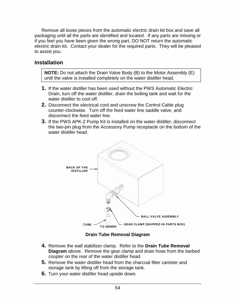
. Remove the wall stabilizer clamp. Refer to the Drain Tube Removal Diagram above. Remove the gear clamp and drain hose from the barbed coupler on the rear of the water distiller head.
. Remove the water distiller head from the charcoal filter canister and storage tank by lifting off from the storage tank.
. Turn your water distiller head upside down.
TUBETO SEWER
GEAR CLAMP (SHIPPED IN PARTS BOX)
BACK OF THEDISTILLER
BALL VALVE ASSEMBLY

55
7. Remove the drain elbow assembly and ball valve assembly using a 12” adjustable wrench. Save this to reinstall as part of the PWS AED-1.
FROM THE EXISTINGMANUAL DRAIN VALVE
VALVE BODY
TEFLON TAPE
NIPPLE
VALVEACTUATOR
PWS AED-1 Plumbing Diagram
8. Refer to the PWS AED-1 Plumbing Diagram above. Use Teflon tape on
all fittings to seal threads. Thread the Valve Body to the existing drain elbow. An arrow on the valve indicates the direction of flow. Flow is from the water distiller head down to the floor drain.
9. Tighten the valve using a 10” adjustable wrench or a 1-1/4” open end wrench so that the pins for the motor assembly box are facing the lid side of the water distiller head.
10.Install a ¾” MPT Close Nipple into the valve using a 10” adjustable wrench. 11.Attach the drain elbow and ball valve assembly that was initially removed. Attach the barbed coupler onto the ball valve and tighten. 12.After checking that all fittings are tight, return the water distiller head to the upright position and reinstall on the charcoal filter canister and storage tank. Reconnect the control cable plug on the storage tank to the control cable receptacle on the bottom of the water distiller head by turning the plug until the splines lock and then turn the locking ring until finger tight.

56
13.Attach the drain hose to the barbed coupler on the ball valve and secure with a gear clamp using a slotted screwdriver. Connect the wall stabilizer clamp. Run the drain hose to a suitable floor drain. The drain hose must have an air gap between the end of the hose and the floor drain. The air gap is necessary so that water can not be siphoned up the drain hose into the boiling chamber and also so that sewage gases do not rise up the drain hose and contaminate the water distiller. 14.Connect the feed water line and turn the feed water line saddle valve on.
Auto Drain Valve Connection Diagram
15.See the Auto Drain Valve Connection Diagram above. Attach the Motor Assembly Box to the drain valve by lining up the holes of the box with the pins on the valve, and snap it into place. The motor can be removed by pressing the release button and pulling the motor away from the valve assembly. 16.Connect the two-pin plug from the valve motor box into the receptacle labelled ‘Accessory Drain’ on the bottom of the water distiller head. If the PWS APK-2 Pump Kit is installed on the water distiller connect the two- pin plug from the pump into the receptacle labelled ‘Accessory Pump’.
17.Plug the electrical cord into the wall outlet. Leave the ball valve in the open position during normal operation. The distiller is now ready to operate and drain the boiling tank automatically.
NOTE: With the automatic drain kit installed the ball valve is always left open while the water distiller is operating. When the water distiller is shut down for cleaning, the ball valve needs to be closed so the cleaning solution in the boiler tank will not drain out. This procedure is described in more detail in the maintenance section of the guide.
VALVE BODY
VALVE ACTUATOR
RELEASE BUTTON
NOTE: PWS APK-2 Pump and PWS AED-1 cord lengths are designed so they cannot be plugged into the incorrect receptacle.

Sediment Pre-Filter Assembly #500359
Charcoal Post-Fil
Pressure Acc
Additional Options
OR
OR
A Sediment Pre-Filter prevents particles from entering the water distiller that mayplug components such as the water solenoid valve. It is most beneficial in applications where the water distillers raw supply water has higher concentrations of sediment.
ter Assembly #500360
The Charcoal Post-Filter Assembly provides the same function as the Filter Canister located between the water distiller head and the storage tank, but has a greater capacity and does not need to be changed as often. This accessory works well in high volume applications.
umulator #080059
Used to help maintain pressure on the outlet side of the optional pump and prevent the pump from starting every time a small amount of water is requiredat the faucet, fridge or humidifier.
57

All O
Water Distiller Cleaner and Descaler 600 g #500102 1600 g #500103
Used for regular maintenance to clean the scale out of the boiling tank. Dissolves water minerals in water distillers, coffeepots, dishwashers or most metal products where water scale is a problem.
Pure Activated Coconut Charcoal for Refillable Charcoal Filter Canisters
250 g #500106 600 g #500107
58
ptions are available from your Precision Water Systems Dealer or Service Center
Contains 100% pure crushed coconut shells that have been steam activated at extremely high temperatures creating a porous grade of activated charcoal. This coconut charcoal can be used along with any type of home or commercial water distiller. Coconut charcoal is used to trap any gases or obnoxious odors that may escape the distillation process. Do not use any other charcoal such as aquarium type.
Tee Valve #034005
Used to divert distilled water from the pantry faucet supply line to other household uses.

59
Model PWS 8-5
Electrical Specifications Voltage Amperage Power Frequency
120VAC 9.2 Amps 1100 Watts 60 Hertz
Water distiller Physical Size Height-w/ lid -w/o lid Width Depth-w/ SG & Drain -w/o SG & Drain
22-3/4” (57.8 cm) 22-1/4” (56.5cm) 17-1/2” (44.5 cm) 12” (30.5 cm) 10-5/8” (27.0cm)
Water distiller Weight Dry: Water distiller and Tank Only
39 lbs. (17.7 kg.)
Water distiller Production Capacity Approx. Prod. Capacity Approx. Daily Prod. Capacity
0.3 US gal/h (1.2 L/h)* 8 US gal/24 hrs.
Storage Tank Capacity Total Storage Capacity Useable Storage Capacity
6 US gal (22.7 L) 4 US gal (15.1 L)
*Note: Performance based on optimum conditions including water temperature, ambient temperature, line voltage, boiling tank cleanliness, boiler fill level, etc
Specifications and Technical Information

60
Wiring List (8GPD AUTO) -120V PART # 500247-S13 SERIES 13 No. Part# Color Ga Length From Conn. ToConn. From Location To Location
1 500232 GRN 16 3" #10RING #14-#16 POWER CORD GROUND POWER CORD 2 500232 BLK 16 14.5" F250 #14-#16 POWER CORD POWER SWITCH #2 POWER CORD 3 500232 WHT 16 14.5" #10RING #14-#16 POWER CORD RESET SWITCH #4 POWER CORD 4 500233 BLKor 18 10" PIGG#18-#22&F250#18-#22 FAN MOTOR (ORG/BLU) HEATER RELAY #4 FAN MOTOR 5 500233 BLKor 18 11" F250 #18-#22&PIGG#18-#22 FAN MOTOR (YLW/WHT) FAN SWITCH #2 FAN MOTOR 6 7 8 9 095001 BLK 16 7" #10RING #14-#16 F187 #14-#16 RESET SWITCH #1 Lower Microswitch COM
10 095000 GRN 16 20" PIGG #14-#16 F250 #14-#16 HEATER RELAY "B" SOLENOID VALVE A 11 095030 BLK 16 19" F187 #14-#16 F250 #14-#16 Upper Microswitch COM SOLENOID VALVE B 12 500236 BLK 18 3.5" F250 #18-#22 PUMP RECEPTACLE FUSE SIDE PUMP RECEPTACLE (SMOOTH) 13 500236 BLK 18 20" #10RING #18-#22 PUMP RECEPTACLE RESET SWITCH #3 PUMP RECEPTACLE (RIBBED) 14 095002 ORG 16 16" #10RING #14-#16 FPIN RESET SWITCH #3 HOLDING TANK RECEPTACLE#115 095003 BLU 16 16" F250 #14-#16 FPIN HEATER RELAY #6 HOLDING TANK RECEPTACLE#216 095004 YLW 16 7" PIGG #14-#16 FPIN SOLENOID VALVE A HOLDING TANK RECEPTACLE#317 095005 RED 16 19" F250 #14-#16 FPIN PUMP RELAY "B" HOLDING TANK RECEPTACLE#418 095006 RED 16 8" F250 #14-#16 #10RING #14-#16 POWER SWITCH #3 RESET SWITCH #2 19 500237 BLK 18 16" PIGG #18-#22 DRAIN RECEPTACLE WATER SWITCH #7 DRAIN RECEPTACLE (RIBBED) 20 500237 BLK 18 16" #10RING #18-#22 DRAIN RECEPTACLE RESET SWITCH #1 DRAIN RECEPTACLE (SMOOTH)21 095007 WHT 16 4" #10RING #14-#16 #10RING #14-#16 RESET SWITCH #1 HEATING ELEMENT "A" 22 095008 YLW 16 13" F250 #14-#16 #10RING #14-#16 HEATER RELAY #4 HEATING ELEMENT "B" 23 095009 BRN 16 7" F250 #14-#16 PIGG #14-#16 PUMP RELAY "A" POWER SWITCH #2 24 095010 WHT 16 3" PIGG#14-#16 F250 #14-#16 PUMP RELAY #6 PUMP RELAY "A" 25 095011 GRN 16 19" F250 #14-#16 F250 #14-#16 PUMP RELAY #9 FUSE END 26 095010 WHT 16 3" PIGG#14-#16 F250 #14-#16 HEATER RELAY "B" HEATER RELAY #9 27 095012 BRN 16 12" F250 #14-#16 #10RING #14-#16 HEATER RELAY #7 RESET SWITCH #3 28 095013 ORG 16 9" F250 #14-#16 #10RING #14-#16 FAN SWITCH #3 RESET SWITCH #1 29 095014 RED 16 11" #10RING #14-#16 F250 #14-#16 HEATING ELEMENT "B" POWER SWITCH #7 30 095010 WHT 16 3" F250 #14-#16 PIGG #14-#16 FAN SWITCH #6 POWER SWITCH #7 31 095010 WHT 16 3" F250 #14-#16 PIGG #14-#16 FAN SWITCH #7 FAN SWITCH #2 32 095015 BRN 16 12" F250 #14-#16 #10RING #14-#16 FAN SWITCH #8 RESET SWITCH #4 33 095016 BLU 16 11" F250 #14-#16 #10RING #14-#16 POWER SWITCH #8 RESET SWITCH #4 34 095010 WHT 16 3" F250 #14-#16 PIGG #14-#16 POWER SWITCH #6 POWER SWITCH #3 35 095017 BLU 16 10" F250 #14-#16 F250 #14-#16 HEATER RELAY #9 WATER SWITCH #7 36 095018 GRN 16 14" F250 #14-#16 #10RING #14-#16 WATER SWITCH #8 RESET SWITCH #4 37 095019 BRN 16 21" F250 #14-#16 PIGG #14-#16 WATER SWITCH #6 SOLENOID VALVE B 38 095020 YLW 16 5" F250 #14-#16 PIGG #14-#16 WATER SWITCH #2 FAN SWITCH #3 39 095021 GRN 16 13" F187 #14-#16 F250 #14-#16 Lower Microswitch NC HEATER RELAY "A" 40 095022 ORG 16 14" F187 #14-#16 F250 #14-#16 Upper Microswitch NC WATER SWITCH #3

61
WIRING DIAGRAM, PWS, 8GPD AUTO

62
Boiling Tank Lid, 25 Capacities
distilled production, 59 storage tank, 59
Charcoal changing, 35
Charcoal Filter installing Canister, 35 replacing charcoal, 35
Cleaning boiling tank using the cleaner descaler, 33 regular inspection and cleaning of the boiling tank,
32 Control Cable, Connection, 24 Descaler
instructions, 33 Drain tube, 21 Electrical
location, 14 requirements, 14
Electrical Connections water distiller head, 52
Feed Water Line Connection, 22 Fuse Replacement, 29 Household Plan for Water Distiller Set Up, 51 Hydrological Cycle, 13 Inspection-boiling tank, 32 Installation
drain tube, 21 feed water line, 22 PWS AED-1 automatic electric drain kit, 53 PWS APK-2 pump kit, 48 sight gauge and valve, 19 water distiller tools, 17
Lid boiling tank, 25 storage tank, 26
Location-suitable distiller, 14 Maintenance and Cleaning, 32
record table, 41 schedule, 41
Manual Fill Operation, 30
Operation, 27 fan switch, 28 normal, 31 overheat reset switch, 29 power switch, 28 storage tank drain valve, 29 water switch, 28
Options charcoal post-filter assembly, 57 charcoal-replacement order, 58 cleaner and descaler-replacement order, 58 pressure accumulator, 57 pump kit installation, 48 PWS AED-1 automatic electric drain kit, 53 PWS APK-2 pump kit, 47 sediment pre-filter assembly, 57 tee valve, fridge, 58
Pantry Faucet Assembly, 50 Production
water, 10 Record of purchase, 5 Safety Precautions, 7 Schematics
8 GPD, 61 Service Center Locator, 46 Shipping Tie Removal, 17 Startup-Summary, 8 Sterilization, 36
liquid-storage tank, pump and water lines, 36 steam-water distiller head, 37 steam-water distiller head, filter canister and storage
tank, 39 Strainer Removal-boiling tank, 33 Terminology, 9 Troubleshooting, 42 Unpacking, 15 Warranty, 6
Precision Water Distiller, 6 registration, 63
Weights, 59 Wiring List
8 GPD, 60
Index

Precision Water Distiller
Warranty Registration
IMPORTANT! Precision Design & Mfg Inc. IMPORTANT!
Thank you for purchasing this fine Precision Water Distiller. Please complete the information below and return it within the next ten days so we may register your purchase.
Last Name First Name
M
63
Address: (Mailing)
City Province/State Country
Zip Code/Postal Code Date of Purchase:
onth Day Year Phone Number: PWS Model Number S
PWS 8-5 Purchased From:
Please fill in information com
Precision Design & M10331 – 105
Westlock, AlbeT7P 2
Or Fax To: 7
erial N
pletely
anufth Strerta, CH7
80-349
umb
an
actuet anad
-495
er
d ma
ring
a
7
il dire
Inc.
ctly
Series:
to:

64
This page left intentionally blank