water pumps - qualvecom
TRANSCRIPT

WATER PUMPStechnical manual
more than just aftermarket

more than just aftermarket

The Metelli technical manual on water pumps for internal combustion engines

DISCLAIMER
1. This TECHNICAL MANUAL constitutes an integral and essential part of the product. It contains important information and instructions about the features and the proper functioning of the product.
2. For safety information and to set up the product properly, please read this TECHNICAL MANUAL carefully before setting up and keep it always at hand to consult it easily.3. To guarantee efficiency and the proper functioning, the product must necessarily be used for the purpose it was designed to.4. Product set up must be carried out by qualified personnel with a specific and technical expertise in the spare parts industry, in compliance with the laws and safety regulations and
according to the instructions included in this TECHNICAL MANUAL.5. Metelli spa is responsible for the product in its original configuration. Any modification or change to the product, to its features or functioning is not authorized.6. Metelli spa reserves the right to make any modifications to the product and to this TECHNICAL MANUAL at any time without notice. Modifications will be included in the future versions
of the TECHNICAL MANUAL.
© Metelli spa. All rights reserved - Total or partial reproduction of contents is forbidden. Every texts, photos and projects in this TECHNICAL MANUAL are exclusively property of Metelli spa in compliance with the Italian laws.

Table of contents
Internal combustion engines and the cooling circuits 1
Operation of a water pump 4
Power take-offs 6
Section of a water pump: main components 8
Water pump design 9
Testing to ensure performance of the water pump 11
The coolants 15
Focus on main components 18
Bearings 18
Impellers 19
Mechanical seals 20
Hubs and pulleys 22
Pump housings 23
Precautions and instructions for proper installation 24
The most common damage to a water pump: causes and analysis 29
Non suitable coolants 29
Air bubbles remaining in the circuit 30
Overheating 31
Unbalanced viscous coupling unit 31
Testing to ensure performance of the water pumpTesting to ensure performance of the water pump

Replacement of other components of the drawing system 32
Bearing overload 33
Improper use of sealing paste 33
Improper installation 35
Assembly of components on the water pump 36
Foreign objects in the circuit 37
Trends 38
Materials 38
Bearings 39
Mechanical seals 40
Solutions 41

Internal combustion engines and their cooling circuits
All fuels (diesel, petrol, methane, etc.)
contain a large amount of energy, this
energy is “chemical” and is released
in terms of pressure and heat during
combustion.
Within the cylinder volume, enclosed
between the motor head and the piston’s
upper surface, the mixture of air and fuel
ignites, transforming chemical energy
into heat and pressure (hence the term
internal combustion engine).
The particular mechanical structure
of the motor is able to transform the
energy released by the combustion into
mechanical energy for the vehicle (or for
other purposes if for example the engine
is an engine for industrial applications).
The temperatures generated inside the 1.1 Temperatures in the various areas of the engine
combustion chamber are extremely
high, and this heat must somehow be
removed, if not the first result would
be an overheating engine, and shortly
thereafter its meltdown.
In order to remove the heat generated
during combustion, all around the cylinder
and inside the cylinder head there are a
large number of channels in which the
engine coolant flows (image 1.1).
The liquid absorbs heat from the walls
of the ducts warming up and as it flows
it transfer this heat to the surrounding
environment through the radiator.
There are two main reasons for engines
to be liquid-cooled: increasingly elevated
power density, increasingly higher operating
temperatures.
1

These two factors have, for some
time, been the main reasons for engine
manufacturers moving towards solutions
with liquid cooling systems, even those
manufacturers who historically had
initially made different choices. Cooling
engines by means of a liquid makes
them more compact (without the bulky
cooling fins that are typical of air-cooled
engines) and capable of operating at
higher temperatures, improving overall
efficiency.
The heat generated by fuel combustion
in the combustion chamber goes to the
surrounding environment by following
different routes: in the exhaust fumes,
by radiation and conduction to the
environment surrounding the motor
itself, and finally through the engine’s
cooling circuit (image 1.2).
Monitoring the temperature of the
engine is important, the proper
functioning thereof depends on
maintaining the correct temperature;
1.2 Internal combustion engine efficiency
1.3 Old engine without water pump
temperatures that are too
high firstly compromise
lubrication and then
the engine materials
themselves, while
temperatures that are
too low make the engine
work with excessive
friction and incorrect
combustion.
The task of the engine
cooling circuit is therefore to keep
the temperature of the engine under
control, handling the thermal transient
and the disposal of heat produced
inside the engine during operation.
The first cooling systems did not
even have a water pump for forced
circulation, but the wide section of the
pipes, combined with a great vertical
development of the radiator, was enough
to generate a natural flow of water by
exploiting the difference in density at
different temperatures (image 1.3).
2

This was possible because the engines
of the past had a very low power density
and the volume inside the engine hood
was extremely wide.
Things changed rapidly with the
passing of time, the design of the cars,
the engines themselves, the space
available, are drastically different from
those of the past.
The cooling circuits of modern engines
therefore have had to adapt becoming
more compact, more efficient and
above all they must operate with
coolant circulation guaranteed by the
presence of a water pump (image 1.4).
The cooling circuits of modern engines
are now real subsystems (with a certain
degree of complexity); main component
of the circuit is the water pump that has
to guarantee the circulation of coolant
throughout the whole circuit.
Since the engines improve their overall
performance especially when operating
at higher and higher temperatures,
many circuits are pressurized.
This means that they can work at higher
temperatures without the cooling liquid
coming to a boil.
Pressurized circuits mean smaller
radiators, better performance of the
engine, but also higher temperatures;
the materials of the entire circuit must
be carefully chosen to withstand the
high temperatures of the pressurized
circuit.
Provided with one or more radiators,
with secondary circuits for heating the
passenger compartment and in some
cases also equipped with a circuit for
the cooling of the turbine, the cooling
circuits have the water pump at their
centre.
1.4 Modern cooling system scheme
3

Operation of a water pump
Although in recent years, water pumps
have undergone major changes related
to changes in the engines onto which
they are mounted, the vast majority
of the water pumps
have maintained a
“classical” structure,
where design rules
have not undergone
drastic changes.
There is always a
mechanical drive,
which is necessary
to draw in rotation
the shaft of the
inner bearing to
which the impeller is
connected, which is
the component that
transfers mechanical
power from the engine to the fluid.
The highly specialized components
such as mechanical seal and the
bearing are now highly industrialized,
2.1 Water Pump with integrated thermostat housing
made with high performance materials
that have evolved over time to last
longer and longer while withstanding
higher and higher temperatures.
4

It is thanks to the action of the impeller
that the coolant is able to overcome
the resistance of the cooling circuit
(usually very tortuous), flow and
therefore be able to transfer heat from
the engine to the radiator, which in turn
transfers it to the external environment
(image 2.1).
Built in this way the water pump works
from the first moment when we start
the engine even when there is no real
need to circulate the fluid. The only
element that is able to ensure that no
water passes through the radiator is
the thermostat, whose housing can be
located in the same body as the water
pump (image 2.2).
Due to its construction technology,
the thermostat is made in order to
open the flow of the coolant towards
the radiator only after it has reached a
specific temperature; this prevents the
coolant from being cooled when in fact
it is not still necessary (for example, 2.2 Modern thermostat
when the engine is still cold).
Taking power from the engine belt, or
by other similar mechanisms, the water
pump has the number of revolutions
which is directly related to the number
of engine revolutions; this also means
that the water pump works from the
moment the engine starts even though
it is cold, that is the reason for the
presence of the thermostat.
5

Power take-offs
The drive of the water pump is
mechanical; this means that the pump
absorbs torque from the engine to
rotate the impeller which circulates the
coolant, in what way? In most cases, the
pump has a pulley which is driven by a
toothed belt, it is generally the same belt
that moves the camshafts of the engine
(image 3.1).
In some cases, for reasons related to
the route of the belt, the water pump
has a pulley without gear teeth,
because the motion is transmitted
only by friction with the back of the belt
(image 3.2).
The use of the timing belt is not the only
case in which the water pump receives
power from the belt indeed there are
3.1 Water pump with drive on engine belt teeth 3.2 Water pump with drive on the back of the engine belt
6

3.3 Water pump with a Poly-V power take off 3.4 Water pump with drive by splined shaft
a large amount of engines that, due
to the layout of the various auxiliaries
have a belt dedicated exclusively to all
these services such as the oil pump,
the power steering pump, the high
pressure oil pump, the air conditioner
compressor, and of course also the
water pump.
In these cases the belts used to provide
the power to services is of type Poly-V;
quieter and easier to use than the
toothed belt, is capable of ensuring
a smooth operation at all speeds of
rotation (image 3.3).
As design was now been abandoned
the classical V-belt typical engine of a
certain age whose performance has
been widely surpassed by Poly-V belt.
The many different design choices that
characterize modern engines are also
reflected in the
water pumps, so
much so that the
solutions to power
a water pump are
not limited only
to the engine belt
(or to the poly-V
belt when the
camshafts are
driven by chain).
There are indeed
a series of variants
in which there is
an actual mechanical coupling that uses
shafts with splined profiles (image 3.4).
The solutions that are actually used can
be many (gears, drives the camshaft
chain, etc.), but these are found in very
few cases: engines of a certain size like
those used for industrial applications
(generators, etc..) or engines for industrial
vehicles.
7
Section of a water pump: main components
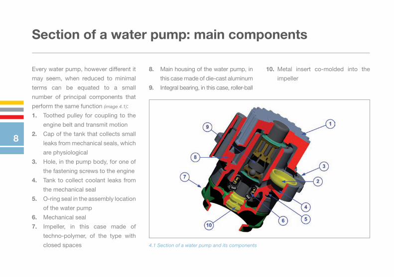
Every water pump, however different it
may seem, when reduced to minimal
terms can be equated to a small
number of principal components that
perform the same function (image 4.1):
1. Toothed pulley for coupling to the
engine belt and transmit motion
2. Cap of the tank that collects small
leaks from mechanical seals, which
are physiological
3. Hole, in the pump body, for one of
the fastening screws to the engine
4. Tank to collect coolant leaks from
the mechanical seal
5. O-ring seal in the assembly location
of the water pump
6. Mechanical seal
7. Impeller, in this case made of
techno-polymer, of the type with
closed spaces
8. Main housing of the water pump, in
this case made of die-cast aluminum
9. Integral bearing, in this case, roller-ball
10. Metal insert co-molded into the
impeller
4.1 Section of a water pump and its components
8

Water pump design
The factors which contribute to literally
give shape to a water pump are many:
performance, reliability, durability,
combined with the highest overall
quality levels are the characteristics
we seek in the development of all our
products.
The geometry of the pump housing
is the result not only of technical
considerations, related to the stress to
which the body itself is subjected, but
also the result of the morphology of the
entire cooling circuit.
Often the water pump is in the meeting
point of the “secondary” coolant
circulation circuits such as passenger
compartment heating, cooling turbine,
etc..
Inserted in the majority of cases in
a space directly in the engine block, 5.1 Structural analysis of water pump housing
the water pumps have to operate in a
difficult environment; high temperatures
of the coolant and the air under the
hood, together with the continuous
vibration of the engine, is the usual
work environment for a water pump.
9
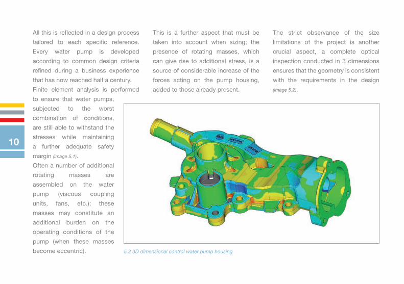
5.2 3D dimensional control water pump housing
All this is reflected in a design process
tailored to each specific reference.
Every water pump is developed
according to common design criteria
refined during a business experience
that has now reached half a century.
Finite element analysis is performed
to ensure that water pumps,
subjected to the worst
combination of conditions,
are still able to withstand the
stresses while maintaining
a further adequate safety
margin (image 5.1).
Often a number of additional
rotating masses are
assembled on the water
pump (viscous coupling
units, fans, etc.); these
masses may constitute an
additional burden on the
operating conditions of the
pump (when these masses
become eccentric).
This is a further aspect that must be
taken into account when sizing; the
presence of rotating masses, which
can give rise to additional stress, is a
source of considerable increase of the
forces acting on the pump housing,
added to those already present.
The strict observance of the size
limitations of the project is another
crucial aspect, a complete optical
inspection conducted in 3 dimensions
ensures that the geometry is consistent
with the requirements in the design
(image 5.2).
10
Testing to ensure performance of the water pump
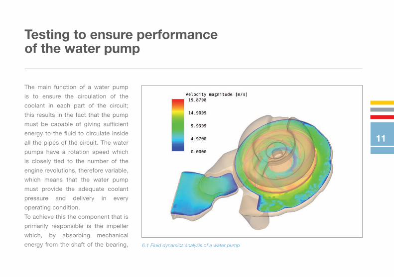
The main function of a water pump
is to ensure the circulation of the
coolant in each part of the circuit;
this results in the fact that the pump
must be capable of giving sufficient
energy to the fluid to circulate inside
all the pipes of the circuit. The water
pumps have a rotation speed which
is closely tied to the number of the
engine revolutions, therefore variable,
which means that the water pump
must provide the adequate coolant
pressure and delivery in every
operating condition.
To achieve this the component that is
primarily responsible is the impeller
which, by absorbing mechanical
energy from the shaft of the bearing, 6.1 Fluid dynamics analysis of a water pump
11
transfers it to the coolant in terms of
kinetic energy.
The design of the impeller and the
volute (when this is part of the water
pump) is closely connected to the
resulting fluid dynamic performance.
These performances are predetermined
by our computational procedures;
subsequently a 3D model of the
impeller is created, sized accordingly
and all the geometry in contact with
the fluid (volute, ecc.); the latter is then
verified by simulation programs.
Fluid dynamic analyses are carried
out in order to validate the calculated
geometry of the impeller and to have
a performance prediction of the water
pump in any condition considered to
be significant for the project, including
verification of the absence of the
cavitation phenomenon in the worst
working conditions (image 6.1).
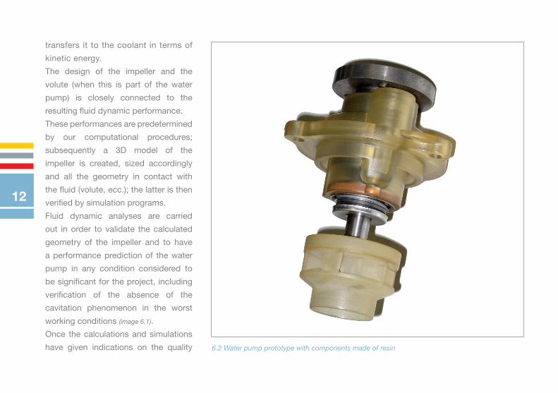
Once the calculations and simulations
have given indications on the quality 6.2 Water pump prototype with components made of resin
12

of the geometry, the whole is physically
realized by means of rapid prototyping
techniques, which allow obtaining the
physical components in a special resin,
starting directly from the 3D CAD model
without the need for any of the traditional
production tooling (image 6.2).
For each water pump intended
for a performance test, special
tooling is developed, based upon
fluid dynamics calculations, whose
purpose is to allow the impeller to
operate in the correct conditions, only
in this way the tests performed give
6.3 Flow rate test fixture
reliable results (image 6.3).
The ability of being able to verify the
occurrence or absence of certain
particular phenomena is extremely
important, for this reason the test
fixtures reproduce, in an extremely
accurate way, the working conditions
that the pump will meet once assembled
in the engine (image 6.4).
Real tests, carried out under strictly
controlled conditions on our test
benches, all undertaken directly
according to our specifications,
provide the evidence of the ultimate
6.4 Transparent test tool
13

success of the entire design
process. This assures us of the
actual achievement of the hydraulic
performance of our products in every
possible condition of use (image 6.5).
The ability to validate and properly
test the products is essential.
Thanks to our long corporate history,
we have the in-house capability to
perform an extensive set of tests at
every level in order to fully characterize
the hydraulic performance (and not
only) of our products (image 6.6).
6.5 Pressure Comparison Chart
6.6 Flow rate comparison chart
14

The coolants
In the cooling circuit of the engine
not only water is circulated! What is
commonly called coolant is a mixture,
in varying percentages (generally
however is 50% -50%), of water and
a substance composed mainly, but
not only, of ethylene glycol.
The reasons for this particular mixture
are multiple:
• Raising the boiling point beyond
the normal threshold of 100 ° C
at atmospheric pressure (in fact,
pure ethylene glycol boils at about
200°C).
• Lowering of the freezing point
well below the temperature at
which pure water normally freezes 7.1 Impeller completely corroded due to incorrect fluid
15

7.2 Two different coolants
(modern antifreeze fluids lower the
freezing point to temperatures of
-30°C and below).
• Increasing the specific heat of the
liquid which allows, with the same
rise in temperature of the fluid, to
remove a greater amount of heat.
• Inhibition of the corrosion processes
that can be activated
within the engine.
While on one side the
ethylene glycol can
influence a change in the
boiling point, freezing
and the capacity of the
fluid to remove heat, the
protection of cooling
circuits from corrosion
deserves a separate
mention.
In the engine, and more
generally in the entire
cooling circuit, there are
a wide variety of metals,
each of these has its own
chemical characteristics
and, brought into contact
with each other, can
16

trigger corrosion phenomena (image 7.1).
The presence in the cooling circuit of a
liquid that can contain chemical elements
which favor this phenomenon leads to a
rapid degradation of some components
of the circuit itself (eg, head gasket,
radiator) with consequent problems of
different nature.
To avoid the onset of galvanic corrosion,
modern coolants have special substances
which act as oxidation inhibitors.
The presence of these substances
gives coolants many properties that
are useful to the motor (corrosion
inhibitors, inhibitors of the deposit of
incrustations, antifoaming properties,
etc.) and are also the reason for which
all liquids have their own particular
color (image 7.2).
A mixture of water and ethylene
glycol, would in itself be perfectly
transparent, but these are colored
by different producers because the
presence of several inhibitory agents,
makes these fluids not always suitable
to be used together.
The reason for this lies in the so-called
bases of the inhibitors, which can
be of three different types: organic,
inorganic and mixed; these bases are
chemically incompatible with each
other and therefore, although the
function of protection of the motor
is the same, a liquid refrigerant must
be used in the cooling circuit that is
produced with the same type of base
as the antioxidant agent.
The liquids, from the point of view of
inhibitor additives they contain, can
be divided into three main groups:
• IAT= Inorganic Additive Technology
(with inorganic additives)
• OAT= Organic Acid Technology
(with additives in organic acid)
• HOAT= Hybrid Organic Acid
Technology (with hybrid additives)
The colour given to the different types
of liquids serves precisely to avoid
mixing liquids not compatible with
each other which would lead to the
formation of substances derived from
chemical reactions and the effect of
antioxidants and corrosion inhibitors
would be annulled.
It must be underlined that every
coolant manufacturer has adopted
his own colour criteria, meaning
that fluids of the same color are
compatible only when they are from
the same manufacturer!
17

Focus on main components
Each component in a water pump
must perform a specific task and
should therefore have characteristics
according to clear requirements.
Although the water pump, like any
other mechanical member, is subject
to normal wear, the use of high
quality components, combined with
a production process always under
strict control, ensures a high degree of
reliability and a long life product.
Before introducing a new component,
our technicians perform selective
homologation tests in order to ensure
that the component’s performance is
in line with expectations, only after
a successful result the component
becomes part of the details that
designers can use in our product.
The bearings are directly responsible
to withstand the loads coming from
the belt tension. Created as a branch
of the classical bearings in common
use, water pump bearings have been
designed on specific dimensions, and
are made to last as long as the expected
Bearings
life of the water pump, without being
subject to any maintenance.
Manufactured already containing the
right amount of long-life grease and the
rolling elements protected by sealing
rings against both grease losses and
the infiltration of water and dirt, modern
8.1 Ball-ball and roller-ball bearing
18

8.3 Impellers manufactured in different ways
water pump bearings, once mounted
in the water pump, do not require any
maintenance.
They are assembled by interference in
the housing and the accurate control
of tolerances of the coupling, together
with the real-time monitoring of the
assembling forces, ensure an optimal
fit with the proper maintenance of the
radial clearance of the bearing (image 8.1).
Made according to two main types of
construction, they differ in the entity
of load they can withstand.
The bearings designed to withstand
higher loads, have in fact one of
the two crowns of rolling elements
consisting of rollers instead of the
normal spheres; this allows increasing
the contact surface between the rolling
elements (the rollers) and the other
parts of the bearing and therefore
increasing the forces that the bearing
is able to withstand.
Impellers
The impellers are the components
that actually ensure the hydraulic per-
formance of a water pump; they are
specifically designed and manufactu-
red to ensure adequate pressure and
delivery to the engine where the pump
must go. 8.2 3D model of a water pump impeller
19

Mechanical seals
The modern mechanical seal is a highly
industrialized component, compact and
built entirely with top quality materials,
it is the component that ensures no
The geometry of each impeller is the
result of precise calculations, it is CAD
designed in the smallest detail and
the performance is verified on our test
benches (image 8.2).
Made with technologies ranging from
sheet metal (including stainless steel)
punched and drawn, to die-cast brass,
cast iron and even the most modern
engineering plastics, the impellers are
produced with technology considered
to be the most suitable in order to
obtain a component that offers the best
performance possible, without ever
compromising reliability (image 8.3).
Such technical freedom, derived from
an experience achieved in half a century,
allows us to have great freedom of
choice by identifying the most suitable
manufacturing process in order to
obtain the project geometry.
leakages from the water pump.
Regardless of the technical solutions
of details, the components that
constitute the mechanical seal are
almost always the same (image 8.4).
1. Stationary part
2. Rotating part
3. Helical spring
4. Slip ring
5. Counterface
6. Bellows
8.4 Section of a typical mechanical seal
20

8.5 Some mechanical seals types 8.6 History of the materials of the rings used in mechanical seals
It can have an apparently different
shape, but the principle on which
it is based is always the same. The
development which it has been
subjected to over the years, have led
this to be more compact and have
a greater duration; nowadays the
mechanical seal is able to perform
continuously even for many thousands
of kilometers (image 8.5).
Extremely hard materials such as
silicon carbide, which until a few years
ago were considered “esoteric”, are
nowadays considered as being normal
in the manufacture of slip rings for all
high quality modern mechanical seals;
this thanks to continuous efforts in the
development of the materials of these
components (image 8.6).
21

Hubs and pulleys
The pulleys, which receive the
mechanical power from the belt or
in rare cases from the chain, are the
components which actually keep the
bearing shaft and consequently the
impeller, in rotation.
The hubs perform the same function,
they are used when, for design
reasons, the overall dimensions
of the pulley are greater than the
area in which there are fixing holes
of the water pump in its seat; from
8.7 Hubs and pulleys for the water pump
the functional point of view they are
considerable on a par.
Mounted by interference on the upper
part of the bearing shaft, they must
be properly secured to withstand the
stresses that come from the engine
belt (image 8.7).
The external geometry of
the pulleys is according
to strict tolerances; only
this way is it possible to
guarantee the perfect
coupling between the
pulley and belt; this results
in a vibration and noise-
free operation and a belt
life in line with the highest
standards.
22

Pump housings
The main housing of the water pump,
made in the great majority of cases in
aluminum alloy, must simultaneously
fulfill several duties.
• It must be able to withstand all the
mechanical stresses.
• Casting must be perfectly airtight
because the housing is an integral
part of the cooling circuit.
8.8 3D model of a water pump housing
• It must be correctly coupled with
the interface on the engine base
and must ensure a perfect seal of
the fluid.
• It must hold the bearing and the
mechanical seal properly with the
correct tolerances.
It is without doubt the component
that requires the greatest amount
of skill in its development, because
each pump is literally a case on its
own (image 8.8).
23

Precautions and instructions for proper installation
The operations for installing a water
pump in replacement to one at the end
of its life, must be performed carefully,
taking care to execute everything in the
best possible way and not forgetting to
do all the necessary checks in relation
to components also directly related to
the water pump.
1. Always work in conditions of safety
and respecting the environment.
2. Allow the work area to be
accessible, if necessary remove the
pieces in order to allow the correct
access to the water pump area.
3. Keep strictly to any instructions
from the manufacturer for the
assembly of the water pump.
4. The cooling circuit must be drained
completely, carefully cleaned and
rinsed; particles present in the circuit
ruin the faces of
the sealing rings,
jeopardizing the
functioning in a
short time.
5. The coolant should be entirely
replaced with a new coolant, which
will fully meet the characteristics
required by the manufacturer.
6. If the water pump is part of the
distribution circuit, the �rst operation
is blocking the motor phase using
any special tools devised by the
manufacturer.
24

7. Once the pump has been removed,
the surface of the crankcase must
be cleaned very well from any
residues of sealant and gasket pieces
that have remained glued, so that
the metal surface is perfectly clean,
degreased and dried.
8. Before doing anything else check
that the replacement water pump is
interchangeable with the new one.
9. If the pump has a gasket, metal or
other type, the sealing paste should
not be used; the gasket supplied with
the pump is adequate to ensure a
perfect seal, make sure the mounting
surface on the crankcase is perfectly
clean.
10. In the case in which the pump
is intended for an installation with
sealing paste, always take care to
use the correct amount only on the
water pump surface without using
too much; excess paste in fact
often ends up in the mechanical seal
causing leakages.
11. Each seal that has been removed
should be replaced with a new one,
never reuse gaskets used even if they
seem in good condition.
25

12. The mounting screws should
be tightened crosswise and, before
tightening them completely, you
must ensure that the pump is
centered correctly and can rotate
freely in its housing.
13. Strictly observe the tightening
torque of the screws indicated by
the manufacturer.
14. Always wait for about 1 hour
with the cooling circuit empty to allow
the sealant that is inside the volute to
polymerize properly.
15. Check the good condition of any
joint (viscous and other) mounted on
the water pump and relative fans;
when viscous joints with unusual
clearances or bent fans or fans
missing even only parts of a blade
are found, replace them.
16. The hose clamps that have been
removed should be checked and if
necessary replaced with new clamps.
17. Concurrently with the water pump
replacement, in addition to the belt,
all components within the belt system
must also be replaced (pulleys, rollers
and / or cylinder tensioners and other
parts related to the system).
26

18. Place the belt correctly following
the manufacturer’s instructions,
especially when this concerns the
timing belt, if special tools are required,
use them.
teeth and splines and have the
foresight to put a small amount of
specific grease on the groove before
insertion into the housing.
20. Check the condition and the
proper operation of the thermostat.
21. Check the operation of temperature
probes.
22. Check the good condition of the
cap of the expansion tank; it should not
be clogged by various incrustations.
23. Cam Shafts must be locked
before disassembling the timing belt
otherwise it’s needed to restore the
correct engine timing by carefully
following the tasks recommended
by the manufacturer.
24. Tighten the belt respecting
the value recommended by the
manufacturer; avoid excessive
tension, allow the engine to run
19. Some water pumps have gears
and spline shafts as drives; ensure
the good condition of the gear
27

manually and check that the position
of the belt is stable; restore the
correct tension if necessary.
25. To check belt tension use the
appropriate instruments that are
able to provide reliable data on the
tension value applied.
26. Once the pump has been
installed and the circuit re-sealed,
ensure its first filling with a liquid
coolant in compliance with the
recommendations from the
manufacturer.
27. Start the engine and leave it
to idle, turn on the heating in the
compartment and continue to re�ll the
coolant from the highest point of the
circuit (generally the expansion tank)
until the level does not drop any more,
wait for the opening of the thermostat
so as to properly �ll also the radiator.
28. Be sure to leave as little air as
possible in the circuit before starting
the engine; dry operation even for a
few seconds of the water pump can
ruin the mechanical seal, causing a
subsequent noisy functioning and/or
loss of liquid.
28

The most common damage to a water pump: causes and analysis
A preparation on the engine in the
area that is intended to accommodate
the water pump, together with the
state-of-the-art execution of assembly
operations, are the basic steps so
that the pump, once in operation,
behaves as expected.
Avoid making a series of common
errors related to installation operations
undertaken incorrectly, this leads to
trivial but annoying drawbacks, such as.
10.1 Rusted components due to unsuitable coolants
Non suitable coolants
The use of unsuitable cooling liquids
can not only create problems to the
engine from a thermal point of view,
but even worse, does not protect from
corrosion that can arise in the entire
circuit. This is due to a corrosion of
29

10.3 Sign of operation with air trapped inside
the circuit metals, according to their
chemical aptitude; the result is a rapid
degradation of all the surfaces of the
cooling circuit.
The use of unsuitable coolants,
polluted or contaminated by particles,
in addition to corrosion, leads to the
limited duration of the mechanical
seal.
10.2 Mechanical seals damaged by unsuitable coolants
Air bubbles remai-ning in the circuit
It is very important to completely
eliminate air bubbles from the cooling
circuit. Residual air bubbles that
cannot end up in the upper expansion
tank make the circuit, at best, work
with reduced section; the presence of
air bubbles that are not removed can
compromise the correct operation of
the water pump (image 10.3).
Leaks of liquid accumulate close to
the bearing, often causing the leakage
of grease and the consequent bearing
failure (images 10.1 and 10.2).
30
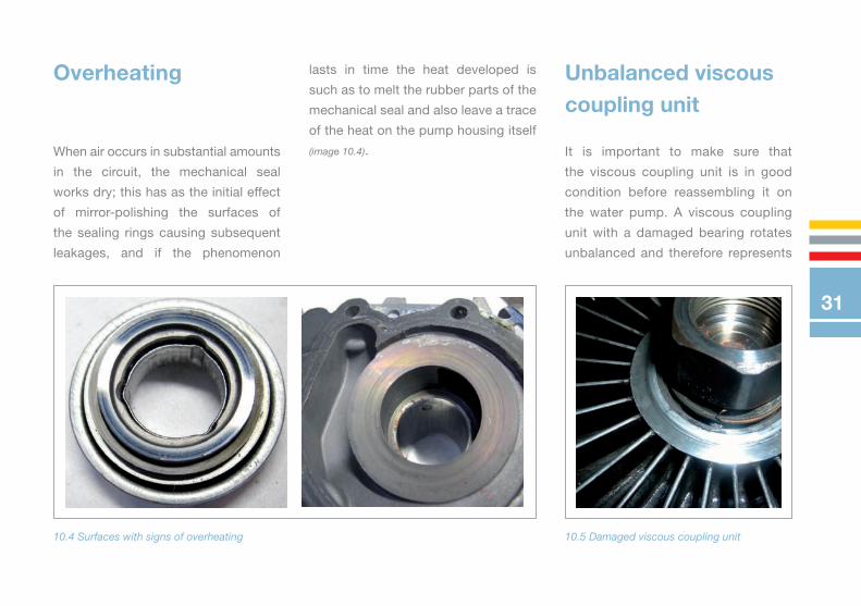
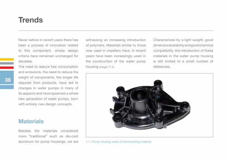
Overheating Unbalanced viscous coupling unit
When air occurs in substantial amounts
in the circuit, the mechanical seal
works dry; this has as the initial effect
of mirror-polishing the surfaces of
the sealing rings causing subsequent
leakages, and if the phenomenon
10.4 Surfaces with signs of overheating 10.5 Damaged viscous coupling unit
It is important to make sure that
the viscous coupling unit is in good
condition before reassembling it on
the water pump. A viscous coupling
unit with a damaged bearing rotates
unbalanced and therefore represents
lasts in time the heat developed is
such as to melt the rubber parts of the
mechanical seal and also leave a trace
of the heat on the pump housing itself
(image 10.4).
31

Replacement of other components of the drawing system
The great majority of water pumps
are driven by a belt, distribution or
service. The first thing to do is a careful
inspection of the belt, if it shows signs
of wear or aging of the material (cracks
in the rubber, shiny surfaces, etc..), must
certainly be changed. When replacing
10.7 Idler and tensioner pulleys
a high stress that is added to the belt
tension. This easily leads to water
pump bearing failure (image 10.5).
In the cases of more serious imbalance,
the stresses reach values so high as to
cause even the breakage of the pump
housing (image 10.6).
the water pump it is always preferable
to replace the pulleys and idlers also, as
when they malfunction they are often the
cause of water pump bearing failure as a
result of an overload in the belt tension
(image 10.7).
10.6 Complete failure of the pump casing due to unbalanced masses
32

Bearing overload
The belt tension with load values
beyond those recommended is due to
working conditions of the bearing being
particularly severe. The result is a life of
the component that is extremely reduced
and in some cases it leads to a complete
failure thereof (images 10.8 and 10.9).
10.9 Bearing components damaged due to overload 10.10 Improper use of sealing material
10.8 Bearing shaft damaged by excessive load
Improper use of sealing paste
The use of sealing paste, is expected
on some references, and on these
should be used in the correct way.
Specific products should always be
used, never generic or other sealants
and it is equally important that they be
used in the correct amounts. The use of
improper sealants or worse still, used
in excessive amount always causes
problems, the accumulation of sealant
residue that ends up in the mechanical
33

seal causes immediate leakages
and there may be lumps of hardened
sealant that end up in the pipes of the
cooling circuit (image 10.10).
If a water pump has been provided
with a metal gasket, O-rings, or other,
this solution is sufficient to guarantee
the seal; sealing paste should not be
applied, it would only jeopardize the
operation of the gasket supplied with
the part (images 10.11 and 10.12).
10.11 Sealant paste incorrectly applied on metal gasket 10.12 Sealant paste Sealant paste incorrectly applied on O-rings
34

Improper installation
It is important that the water pump
assembly operations in the housing
are done properly, carefully following
any special instructions attached.
10.13 Damage caused by incorrect installation
An installation performed incorrectly
can easily bring the water pump to
work badly or even worse can damage
some sensitive components such as
seals, or in some cases even the water
pump housing itself (image 10.13).
35

Assembly of components on the water pump
Some water pumps carry other
components that must be installed
after the water pump has been
assembled on the engine. Correctly
executing the assembly operations
of these components is crucial; in
particular it is extremely important to
absolutely avoid hitting the bearing
spindle, this would damage the sliding
grooves of the bearing balls and in
some cases could even break the
shaft itself (image 10.14).
10.14 bearing shaft broken due to incorrect assembly operations
36

Foreign objects in the circuit
Perform an accurate cleaning of
the entire circuit when replacing
the water pump. It is possible that
there are foreign objects inside the
housing space which, when they are
moved by the coolant flow, can cause
considerable problems.
When the impeller encounters a foreign
object it is irreparably damaged,
creating potential problems not only to
all the cooling circuit, but it is possible
that damage will occur even to the
timing system (image 10.15).
10.15 Impeller damaged by foreign object in the circuit
37
Trends
Never before in recent years there has
been a process of innovation related
to this component, whose design
criteria have remained unchanged for
decades.
The need to reduce fuel consumption
and emissions, the need to reduce the
weight of components, the longer life
required from products, have led to
changes in water pumps in many of
its aspects and have spawned a whole
new generation of water pumps, born
with entirely new design concepts.
Besides the materials considered
more “traditional” such as die-cast
aluminum for pump housings, we are
Materials
11.1 Pump housing made of thermosetting material
witnessing an increasing introduction
of polymers. Materials similar to those
now used in impellers have, in recent
years have been increasingly used in
the construction of the water pump
housing (image 11.1).
Characterized by a light weight, good
dimensional stability and good chemical
compatibility, the introduction of these
materials in the water pump housing
is still limited to a small number of
references.
38

11.2 3D Model of Water pump with bearing (green section) outside the housing
Along with specific water pump bearings
that the market has been used to seeing
for many years, due to continued
increases in power that the engines
undergo during their life on the market,
belts are more and more stressed and
have led to the introduction of a new
generation of bearings, more similar to
the bearings we find in the air conditioner
compressor pulleys (image 11.2).
Unlike bearings assembled inside the
pump housing, these bearings are to be
mounted externally to the housing; this
allows having a larger bearing which
is able to withstand higher stresses
and thus to guarantee a trouble-free
operation also with those motors which
during their development have seen
considerable increases in the values of
the belt tension.
Bearings
39

The monobloc mechanical seals have
evolved steadily over the years in the
geometry and materials employed
especially in sealing rings; this progress
has made them more compact and
more durable at the same time.
Recently an entire generation of newly
developed mechanical seals has made
its appearance on the market (image 11.3).
More similar to oil sealing rings than to
the classic mechanical seals, this new
generation of components has the seal
along the bearing shaft surface.
Provided with an higher resistance to dry
operation, and a lower resisting torque,
these are seals that use innovative
solutions and materials and due to their
geometry their dimensions have been
really reduced to the minimum.
Mechanical seals
11.3 Lip seal for water pump
40

Solutions
The development trends of today are
bringing onto the market a wide range
of newly designed water pumps, whose
purpose is to meet the new needs
of pumping ef�ciency and reduce
engine emissions. Due to its natural
characteristics, a traditional water
pump is designed to dissipate heat
from the engine when it is operating
at maximum performance. This type
of operation is, in the real condition of
engine usage, not very common; for an
automotive engine top performance is
requested from the engine less than
10% of his entire life.
The solutions that the designers have
developed to meet the need of having a
water pump that is adequate for proper
engine cooling, but more optimized to
meet the multiple needs of a modern 12.1 Section of the switchable water pump patented by Metelli
41

engine, are very different.
These solutions have led to a new
generation of water pumps that are
‘switchable’. This innovative model,
even though it is still driven by the belt,
allows the flow of water in the cooling
circuit to be interrupted in different
ways: by closing the pump lines, or by
disconnecting the pulley and blocking
the rotation of the impeller.
Metelli has optimized its product
line, introducing an innovative, EU-
patented solution – the most reliable
on the market today.
This solution makes it possible to
interrupt the flow of liquid in the cooling
circuit thanks to a pneumatically
activated gate valve.
The gate valve is actuated when a
depression is created in the ‘vacuum
chamber’ of the pump. The name of
this chamber reflects the fact that the
depression produced by the vacuum
pump of the brake servo is used.
From the outside, the switchable water
pump resembles an ordinary water
pump with a slight enlargement in
the area where the bearing is located.
Here, in this enlarged area, is the entire
mechanism responsible for actuating
the gate valve around the impeller.
This mechanism is potentially harmful
for the motor because it can interrupt
the water flow in the cooling circuit. For
this reason it was designed to be ‘fail
safe’, that is to ensure the passage of
fluid even if it malfunctions. One more
way to guarantee the reliability of this
innovative solution.
We are witnessing a true revolution in
the way of designing a product that has
remained fundamentally unchanged in
40 years.
These new approaches to the design
of the water pump started to bring to
the market a whole new generation
of more sophisticated products, more
efficient and with performances more
in line with the requirements of modern
engines.
42

NOTE
43

NOTE
44

more than just aftermarket

METELLI SPA - Via Bonotto, 3/5 - 25033 Cologne (BS) Italia - Tel. +39 030.705711 - Fax +39 030.7057237
[email protected] - www.metellispa.it
solu
zion
egro
up.co
m
Man
ual
e Te
cnic
o P
A 2
014
EN
G -
90
-50
77