water-cooled screw chillers€“eimwc00504-14en - 7/68 nomenclature eww q 380 b - s s 0 01 machine...
TRANSCRIPT
Water-cooled screw chillers EWWQ380B-SS~EWWQC20B-SS EWWQ420B-XS~EWWQC21B-XS 50Hz – Refrigerant: R-410A Original Instructions
Installation, Operation and Maintenance Manual D–EIMWC00504-14EN

D-EIMWC00504-14EN - 2/68
Contents General information ………………………………………………………………………………………………………………….4
Warnings for the operator ................................................................................................................................................. 4
Assistance ........................................................................................................................................................................ 4
Spare parts ....................................................................................................................................................................... 4
Receiving the machine ..................................................................................................................................................... 4
Checks ............................................................................................................................................................................. 5
Purpose of this manual ..................................................................................................................................................... 5
Important information on the refrigerant used ................................................................................................................... 5
NOMENCLATURE ........................................................................................................................................................... 7
Operating limits .................................. ............................................................................................................................. 17
Storing ............................................................................................................................................................................ 17
Operation ........................................................................................................................................................................ 17
Mechanical Installation ........................... ........................................................................................................................ 18
Shipping ......................................................................................................................................................................... 19
Responsibility ................................................................................................................................................................. 19
Safety ............................................................................................................................................................................. 19
Moving and lifting ........................................................................................................................................................... 19
Positioning and assembly ............................................................................................................................................... 20
Minimum space requirements ........................................................................................................................................ 21
Ventilation ....................................................................................................................................................................... 21
Sound protection ............................................................................................................................................................ 21
Water piping ................................................................................................................................................................... 21
Water treatment .............................................................................................................................................................. 23
Evaporator and exchangers anti-freeze protection ......................................................................................................... 23
Installing the flow switch ................................................................................................................................................. 23
Electrical Installation ............................ .......................................................................................................................... 37
General specifications .................................................................................................................................................... 37
Electrical components .................................................................................................................................................... 40
Electrical wiring .............................................................................................................................................................. 40
Electrical heaters ............................................................................................................................................................ 40
Water pump control ........................................................................................................................................................ 40
Unit On/Off remote control – Electrical wiring ................................................................................................................. 40
Double Setpoint – Electrical wiring ................................................................................................................................. 40
External water Setpoint reset – Electrical wiring (Optional) ............................................................................................ 40
Unit limitation – Electrical wiring (Optional) .................................................................................................................... 41
Operation ......................................... ................................................................................................................................ 42
Operator’s responsibilities .............................................................................................................................................. 42
Description of the machine ............................................................................................................................................. 42
Description of the refrigeration cycle .............................................................................................................................. 42
Description of the refrigeration cycle with partial heat recovery...................................................................................... 47
Controlling the partial recovery circuit and installation recommendations ...................................................................... 47
Compression process ..................................................................................................................................................... 48
Pre-startup checks ................................. ......................................................................................................................... 52
General........................................................................................................................................................................... 52
Units with external water pump ...................................................................................................................................... 53
Electrical power supply ................................................................................................................................................... 53
Unbalance in power supply voltage ................................................................................................................................ 53
Electrical heaters power supply ...................................................................................................................................... 53
Emergency Stop ............................................................................................................................................................. 53
Startup procedure .................................. ......................................................................................................................... 54
Turning on the machine .................................................................................................................................................. 54
Seasonal shutdown ........................................................................................................................................................ 55
Starting up after seasonal shutdown .............................................................................................................................. 55
System maintenance................................. ...................................................................................................................... 56
General........................................................................................................................................................................... 56
Compressor maintenance .............................................................................................................................................. 56
Lubrication ...................................................................................................................................................................... 56
Replacement of filter dryer ............................................................................................................................................. 58
Procedure to replace the filter dryer cartridge ................................................................................................................ 59
Replacement of filter dryer ............................................................................................................................................. 59
Procedure to replace the filter dryer cartridge ................................................................................................................ 59
Rplacement of the oil filter .............................................................................................................................................. 60
Fr3200 compressor ............................................................................................................................................. 60
FR4 compressor ................................................................................................................................................. 61
Fr4200 compressor ............................................................................................................................................. 61
Refrigerant charge .......................................................................................................................................................... 62
Procedure to replenish refrigerant .................................................................................................................................. 63
Standard Checks .................................... ......................................................................................................................... 64
Temperature and pressure sensors ............................................................................................................................... 64
Test sheet ........................................ ................................................................................................................................ 65
D–EIMWC00504-14EN - 3/68
Water side measurements .............................................................................................................................................. 65
Refrigerant side measurements ..................................................................................................................................... 65
Electrical measurements ................................................................................................................................................ 65
Service and limited warranty ....................... ................................................................................................................... 66
Obligatory routine checks and starting up apparatus es under pressure ................................. ................................. 67
Important information regarding the refrigerant use d ................................................................................................. 67
List of tables Table 1 – EWWQ380B-SS~EWWQ730B-SS - Technical Data ........................................................................................... 8
Table 2 – EWWQ800B-SS~EWWQC10B-SS - Technical Data .......................................................................................... 9
Table 3 – EWWQC11B-SS~EWWQC15B - Technical Data ............................................................................................. 10
Table 4 – EWWQC16B-SS~EWWQC20B-SS - Technical Data ....................................................................................... 11
Table 5 – EWWQ420B-XS~EWWQ800B-XS - Technical Data ......................................................................................... 12
Table 6 – EWWQ970B-XS~EWWQC13B-XS - Technical Data ........................................................................................ 13
Table 7 – EWWQC14B-XS~EWWQC19B-XS - Technical Data ....................................................................................... 14
Table 8 – EWWQC20B-XS-EWWQC21B-XS - Technical Data ........................................................................................ 15
Table 9 - Sound levels EWWQ B-SS ................................................................................................................................ 16
Table 10 - Sound levels EWWQ B-XS .............................................................................................................................. 16
Table 11 – Acceptable water quality limits ........................................................................................................................ 23
Table 12 – Electrical data EWWQ B-SS Unit .................................................................................................................... 38
Table 13 – Electrical data EWWQ B-XS Unit .................................................................................................................... 39
Table 14 - Typical operating conditions with compressors at 100% .................................................................................. 54
Table 15 – Routine maintenance programme ................................................................................................................... 58
List of Figures Fig. 1 – Operating limits .................................................................................................................................................... 18
Fig. 2 - Lifting the unit ....................................................................................................................................................... 20
Fig. 3 – Minimum clearance requirements for machine maintenance ............................................................................... 21
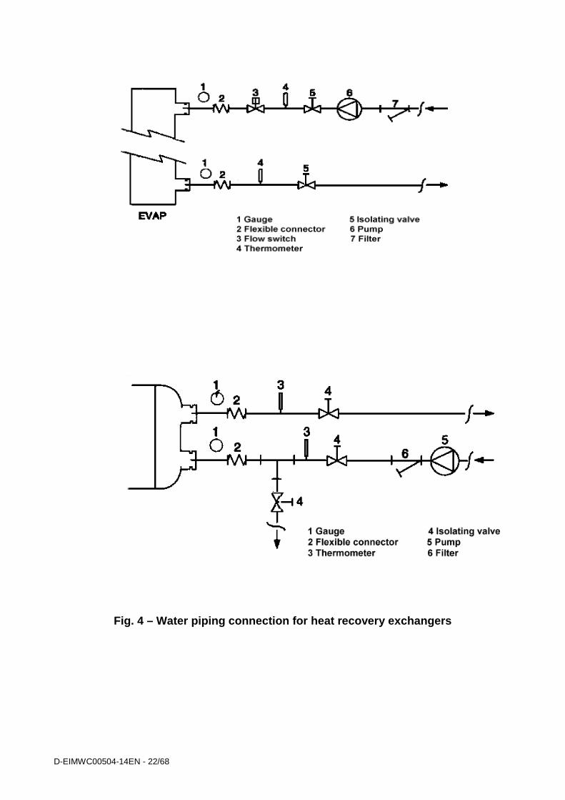
Fig. 4 – Water piping connection for heat recovery exchangers ........................................................................................ 22
Fig. 5 - Adjusting the safety flow switch............................................................................................................................. 24
Fig. 6 – Evaporator pressure drop – EWWQ B-SS ........................................................................................................... 25
Fig. 7 – Evaporator pressure drop – EWWQ B-SS ........................................................................................................... 26
Fig. 8 – Evaporator pressure drop - EWWQ B-XS ............................................................................................................ 27
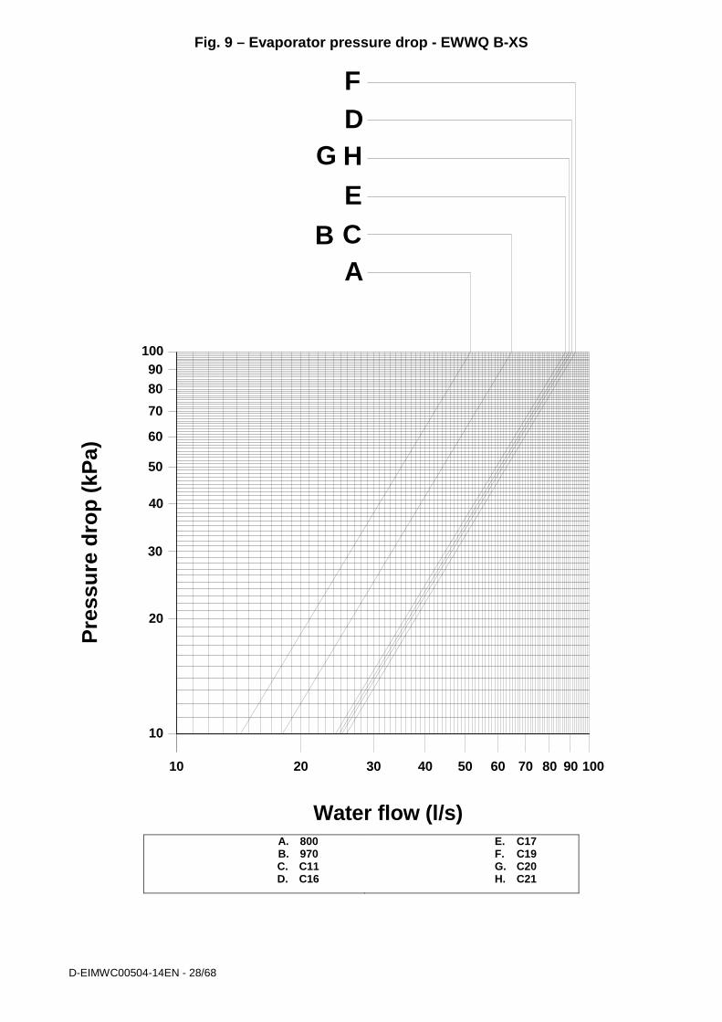
Fig. 9 – Evaporator pressure drop - EWWQ B-XS ............................................................................................................ 28
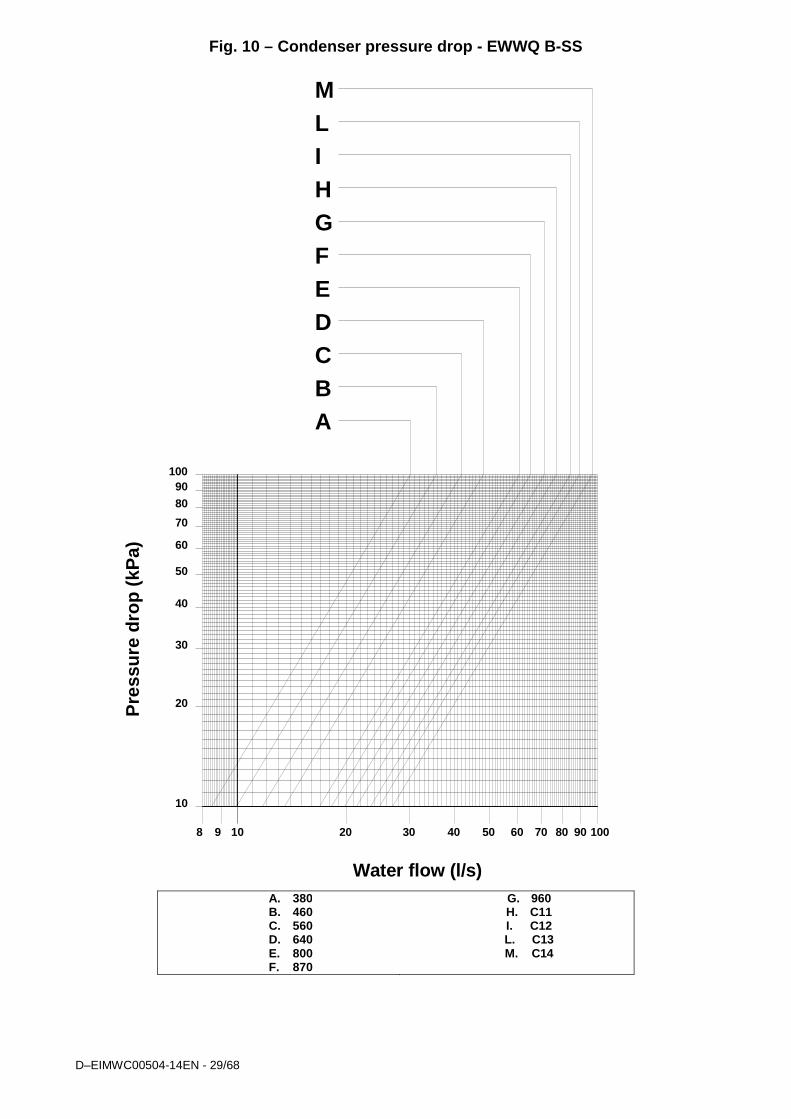
Fig. 10 – Condenser pressure drop - EWWQ B-SS .......................................................................................................... 29
Fig. 11 – Condenser pressure drop - EWWQ B-SS .......................................................................................................... 30
Fig. 12 – Condenser pressure drop - EWWQ B-XS .......................................................................................................... 31
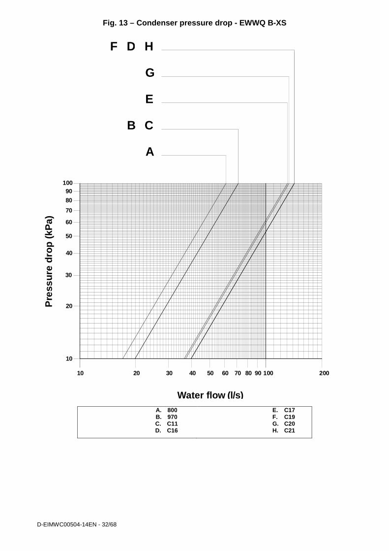
Fig. 13 – Condenser pressure drop - EWWQ B-XS .......................................................................................................... 32
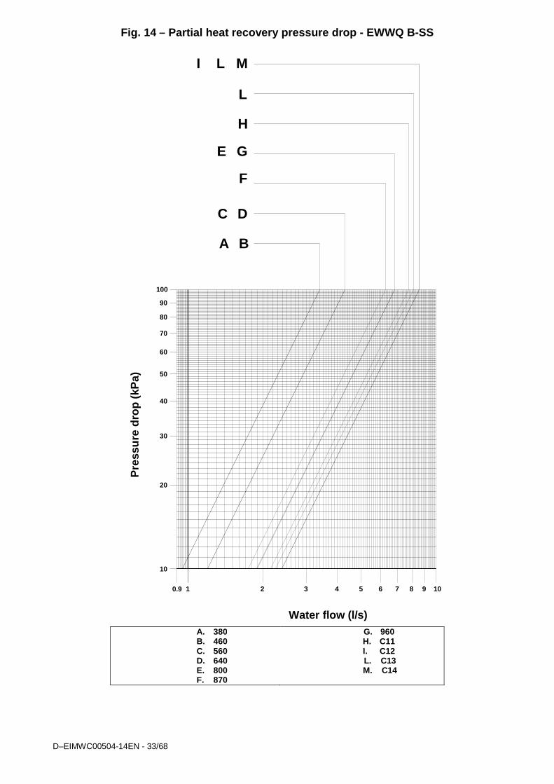
Fig. 14 – Partial heat recovery pressure drop - EWWQ B-SS ........................................................................................... 33
Fig. 15 – Partial heat recovery pressure drop - EWWQ B-SS ........................................................................................... 34
Fig. 16 – Partial heat recovery pressure drop - EWWQ B-XS ........................................................................................... 35
Fig. 17 – Partial heat recovery pressure drop - EWWQ B-XS ........................................................................................... 36
Fig. 18 – User connection to the interface terminal board ................................................................................................. 41
Fig. 19 - Refrigeration cycle of the EWWQ B-SS / EWWQ B-XS DUAL Fr4 unit .............................................................. 43
Fig. 20 - Refrigeration cycle of the EWWQ B-SS / EWWQ B-XS Mono Fr4 unit ............................................................... 44
Fig. 21 - Refrigeration cycle of the EWWQ B-SS / EWWQ B-XS DUAL 3200 unit ............................................................ 45
Fig. 22 - Refrigeration cycle of the EWWQ B-SS / EWWQ B-XS Mono 3200 unit ............................................................ 46
Fig. 23 - Picture of Fr4100 compressor ............................................................................................................................. 48
Fig. 24 – Picture of Fr3200 compressor ............................................................................................................................ 48
Fig. 25 - Compression process ......................................................................................................................................... 49
Fig. 26 - Refrigeration capacity control mechanism of compressor Fr3200 – Fr4 ............................................................. 50
Fig. 27 - Capacity control mechanism ............................................................................................................................... 51
Fig. 28 - Installation of control devices for Fr4 compressor ............................................................................................... 57
Fig. 29 - Installation of control devices for Fr3200 compressor ......................................................................................... 57
D-EIMWC00504-14EN - 4/68
General information
IMPORTANT The units described in the present manual represent a valuable investment. Maximum care should be taken to ensure correct installation and appropriate working conditions of the units. Installation and maintenance must be performed by qualified and specifically trained personnel only. Correct maintenance of the unit is indispensable for its safety and reliability. Manufacturer’s service centres are the only having adequate technical skill for maintenance.
CAUTION This manual provides information about the features and procedures for the complete series. All units are delivered from factory as complete sets which include wiring diagrams and dimensional drawings with size, weight and features of each model. WIRING DIAGRAMS AND DIMENSIONAL DRAWINGS MUST BE CONSIDERED ESSENTIAL DOCUMENTS OF THIS MANUAL In case of any discrepancy between this manual and the two aforesaid documents, please refer to the wiring diagram and dimensional drawings.
WARNING
Before starting the installation of the unit, please read this manual carefully. Starting up the unit is absolutely forbidden if all instructions contained in this manual are not clear.
Warnings for the operator • READ THIS MAINTENANCE AND USE MANUAL BEFORE USING THE UNIT
• THE OPERATOR MUST BE TRAINED AND INSTRUCTED ON HOW TO USE THE UNIT
• THE OPERATOR MUST STRICTLY FOLLOW ALL INSTRUCTIONS, SAFETY REGULATIONS AND LIMITATIONS REGARDING THE USE OF THE UNIT.
Key to symbols
Important note: failure to respect the instruction can damage the unit or compromise functioning
Note regarding safety in general or respect of laws and regulations
Note concerning electrical safety Safe use and maintenance of the unit, as explained in this Maintenance and Use Manual, is fundamental to prevent any accidents occurring to operators during both operation and maintenance as well as during repair work. Therefore, it is highly recommended that this document be read carefully, complied with and stored safely. Assistance Should additional maintenance be required, it is advisable to consult authorised staff before carrying out any repair work.
Spare parts Spare parts to be used for maintenance of the unit must be original. Therefore, always consult the manufacturer.
Receiving the machine The machine must be inspected for any possible damage immediately upon reaching its final place of installation. All components described in the delivery note must be carefully inspected and checked; any damage must be reported to the carrier. Before connecting the machine to earth, check that the model and power supply voltage shown on the nameplate are correct. Responsibility for any damage after acceptance of the machine cannot be attributed to the manufacturer.
D–EIMWC00504-14EN - 5/68
Checks To prevent the possibility of incomplete delivery (missing parts) or transportation damage, please perform the following checks upon receipt of the machine:
a) Before accepting the machine, please verify every single component in the consignment. Check for any damage. b) In the event that the machine has been damaged, do not remove the damaged material. A set of photographs
are helpful in ascertaining responsibility. c) Immediately report the extent of the damage to the transportation company and request that they inspect the
machine. d) Immediately report the extent of the damage to the manufacturer representative, so that arrangements can be
made for the required repairs. In no case must the damage be repaired before the machine has been inspected by the representative of the transportation company.
Purpose of this manual The purpose of this manual is to allow the installer and the qualified operator to carry out all required operations in order to ensure proper installation and maintenance of the machine, without any risk to people, animals and/or objects. This manual is an important supporting document for qualified personnel but it is not intended to replace such personnel. All activities must be carried out in compliance with local laws and regulations.
Important information on the refrigerant used This product contains fluorate gases which have a greenhouse effect and which are covered by the Kyoto protocol. Do not release such gases into the atmosphere. Type of refrigerant: R410A GWP value(1) = 1975 The quantity of refrigerant used is indicated on the identity plate with the name of the unit. Routine inspections may be necessary pursuant to local and/or European laws, to check on possible refrigerant leakage. For more detailed information, contact your local dealer. (1) GWP=Global warming potential
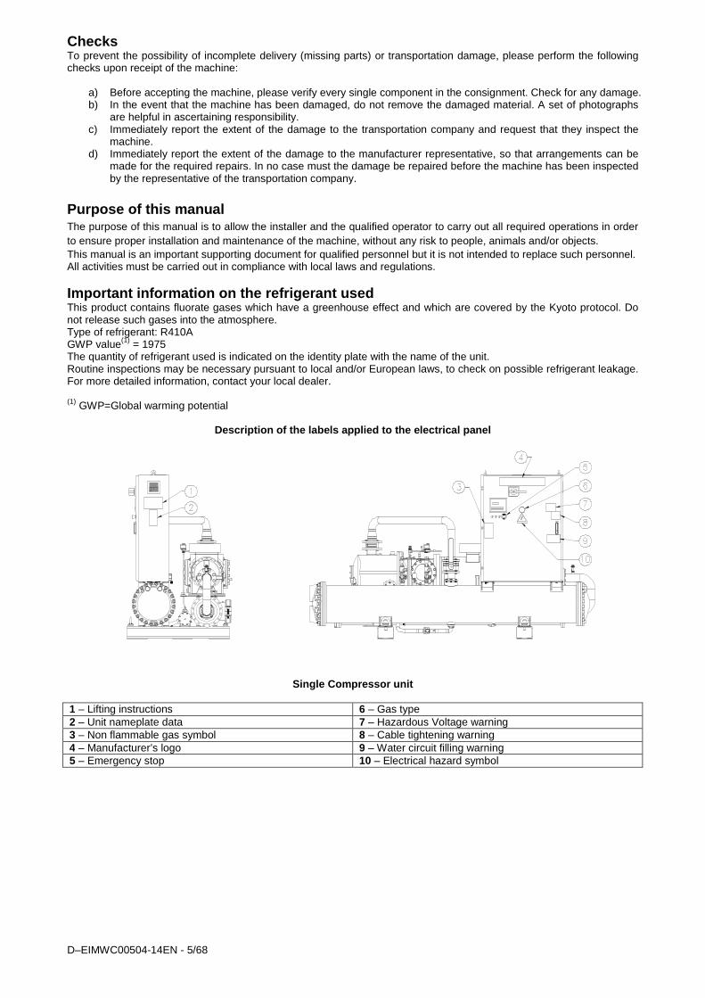
Description of the labels applied to the electrical panel
Single Compressor unit 1 – Lifting instructions 6 – Gas type 2 – Unit nameplate data 7 – Hazardous Voltage warning 3 – Non flammable gas symbol 8 – Cable tightening warning 4 – Manufacturer’s logo 9 – Water circuit filling warning 5 – Emergency stop 10 – Electrical hazard symbol

D-EIMWC00504-14EN - 6/68
Two Compressors Unit
1 – Unit nameplate data 6 – Non flammable gas symbol 2 – Lifting instructions 7 – Manufacturer’s logo 3 – Hazardous Voltage warning 8 – Gas type 4 – Cable tightening warning 9 – Electrical hazard symbol 5 – Water circuit filling warning 10 – Emergency stop
D–EIMWC00504-14EN - 7/68
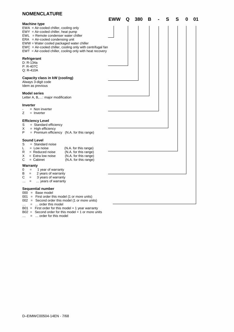
NOMENCLATURE EWW Q 380 B - S S 0 01
Machine type EWA = Air-cooled chiller, cooling only EWY = Air-cooled chiller, heat pump EWL = Remote condenser water chiller ERA = Air-cooled condensing unit EWW = Water cooled packaged water chiller EWC = Air-cooled chiller, cooling only with centrifugal fan EWT = Air-cooled chiller, cooling only with heat recovery Refrigerant D: R-134a P: R-407C Q: R-410A Capacity class in kW (cooling) Always 3-digit code Idem as previous Model series Letter A, B,…: major modification Inverter - = Non inverter Z = Inverter Efficiency Level S = Standard efficiency X = High efficiency P = Premium efficiency (N.A. for this range) Sound Level S = Standard noise L = Low noise (N.A. for this range) R = Reduced noise (N.A. for this range) X = Extra low noise (N.A. for this range) C = Cabinet (N.A. for this range) Warranty 0 = 1 year of warranty B = 2 years of warranty C = 3 years of warranty … = … years of warranty Sequential number 000 = Base model 001 = First order this model (1 or more units) 002 = Second order this model (1 or more units) … = … order this model B01 = First order for this model + 1 year warranty B02 = Second order for this model + 1 or more units … = … order for this model

D-EIMWC00504-14EN - 8/68
TECHNICAL SPECIFICATIONS Table 1 – EWWQ380B-SS~EWWQ730B-SS - Technical Data TECHNICAL SPECIFICATIONS EWWQ B-SS 380 460 560 640 730 Capacity (1) Cooling kW 380 464 562 637 727
Capacity control Type Stepless Minimum capacity % 25 25 25 25 25
Unit power input (1) Cooling kW 86 104 128 144 168 EER (1) 4,44 4,46 4,40 4,41 4,37 ESEER 5,16 5,21 5,22 5,22 4,95
Casing Colour Ivory White (Munsell code 5Y7.5/1) Material Galvanized and painted steel sheet
Dimensions Unit Height mm 1849 1849 2001 2001 1848 Width mm 1140 1140 1276 1276 1314 Depth mm 3373 3373 3454 3454 3535
Weight Unit kg 1933 1967 2283 2332 2407 Operating Weight kg 2135 2169 2543 2628 2777
Water heat exchanger Evaporator
Type Shell & tubes Water volume l 124 118 176 170 274 Nominal water flow rate Cooling l/min 18,2 22,2 26,8 30,4 34,7
Nominal Water pressure drop Cooling kPa 47 63 43 46 53
Insulation material Closed cell foam elastomer
Water heat exchanger Condenser
Type Shell & tubes Number of condensers No. 1 1 1 1 1
Water volume l 79 92 84 126 97
Nominal water flow rate Cooling l/min 22,9 27,2 32,9 37,3 42,7
Nominal Water pressure drop Cooling kPa 58 62 66 63 15
Insulation Material Expanded elastomer
Compressor Type Semi-hermetic single screw compr. Oil charge l 16 16 16 16 16 Quantity 1 1 1 1 1
Sound level Sound Power (2) Cooling dBA 100,2 101,2 102,3 102,3 101,5 Sound Pressure (2) Cooling dBA 82,2 83,0 83,9 83,9 83,2
Refrigerant circuit Refrigerant type R410A R410A R410A R410A R410A N. of circuits 1 1 1 1 1
Piping connections Evaporator water inlet/outlet mm 168.3 168.3 219.1 219.1 219.1 Pipinogconnections Condenser water inlet/outlet in 5” 5” 6” 6” 6” Safety devices High pressure (pressure switch) Safety devices Low pressure (pressure switch) Safety devices Emergency stop Safety devices High discharge temperature on the compressor Safety devices Phase monitor Safety devices Low pressure ratio Safety devices High oil pressure drop Safety devices Low oil pressure
Notes (1) Cooling capacity, unit power input in cooling and EER are based on the following conditions: evaporator 12°/ 7°C; condenser 30°/ 35°C, unit at full load operation.
Notes (2) The values are according to ISO 3744 and are referred to evaporator 12°/ 7°C, condenser 30°/ 35°C, full load operation.
D–EIMWC00504-14EN - 9/68
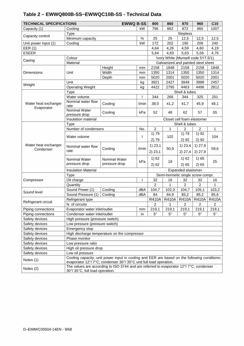
Table 2 – EWWQ800B-SS~EWWQC10B-SS - Technical Data TECHNICAL SPECIFICATIONS EWWQ B-SS 800 860 870 960 C10 Capacity (1) Cooling kW 796 862 872 960 1007
Capacity control Type Stepless Minimum capacity % 25 25 12,5 12,5 12,5
Unit power input (1) Cooling kW 172 202 190 209 240 EER (1) 4,64 4,26 4,59 4,60 4,19 ESEER 5,64 4,83 5,63 5,59 4,76
Casing Colour Ivory White (Munsell code 5Y7.5/1) Material Galvanized and painted steel sheet
Dimensions Unit Height mm 2158 1848 2158 2158 1848 Width mm 1350 1314 1350 1350 1314 Depth mm 5020 2001 5020 5020 2001
Weight Unit kg 3921 2427 3949 3988 2457 Operating Weight kg 4422 2795 4463 4496 2812
Water heat exchanger Evaporator
Type Shell & tubes Water volume l 344 266 344 325 251 Nominal water flow rate Cooling l/min 38,0 41,2 41,7 45,9 48,1
Nominal Water pressure drop Cooling kPa 52 48 62 57 55
Insulation material Closet cell foam elastomer
Water heat exchanger Condenser
Type Shell & tubes Number of condensers No. 2 1 2 2 1
Water volume l 1) 79
2) 79 102
1) 79
2) 92
1) 92
2) 92 104
Nominal water flow rate Cooling l/min
1) 23,1
2) 23,1 50,9
1) 23,4
2) 27,4
1) 27,9
2) 27,9 59,6
Nominal Water pressure drop
Nominal Water pressure drop kPa
1) 62
2) 62 19
1) 62
2) 65
1) 65
2) 65 25
Insulation Material Expanded elastomer
Compressor Type Semi-hermetic single screw compr. Oil charge l 32 16 32 32 16 Quantity 2 1 2 2 1
Sound level Sound Power (1) Cooling dBA 104,7 102,3 104,7 105,1 103,2 Sound Pressure (1) Cooling dBA 84 84,9 85,2 85,2 85,6
Refrigerant circuit Refrigerant type R410A R410A R410A R410A R410A N. of circuits 2 1 2 2 2
Piping connections Evaporator water inlet/outlet mm 219,1 219,1 219,1 219,1 219,1 Piping connections Condenser water inlet/outlet in 5” 5" 5” 5” 5” Safety devices High pressure (pressure switch) Safety devices Low pressure (pressure switch) Safety devices Emergency stop Safety devices High discharge temperature on the compressor Safety devices Phase monitor Safety devices Low pressure ratio Safety devices High oil pressure drop Safety devices Low oil pressure
Notes (1) Cooling capacity, unit power input in cooling and EER are based on the following conditions: evaporator 12°/ 7°C; condenser 30°/ 35°C unit full load operation.
Notes (2) The values are according to ISO 3744 and are referred to evaporator 12°/ 7°C, condenser 30°/ 35°C, full load operation.
D-EIMWC00504-14EN - 10/68
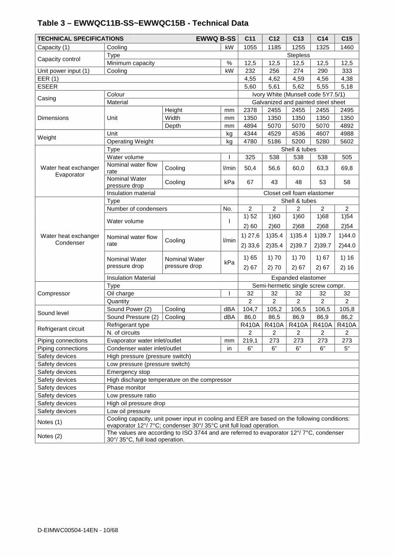
Table 3 – EWWQC11B-SS~EWWQC15B - Technical Data TECHNICAL SPECIFICATIONS EWWQ B-SS C11 C12 C13 C14 C15 Capacity (1) Cooling kW 1055 1185 1255 1325 1460
Capacity control Type Stepless Minimum capacity % 12,5 12,5 12,5 12,5 12,5
Unit power input (1) Cooling kW 232 256 274 290 333 EER (1) 4,55 4,62 4,59 4,56 4,38 ESEER 5,60 5,61 5,62 5,55 5,18
Casing Colour Ivory White (Munsell code 5Y7.5/1) Material Galvanized and painted steel sheet
Dimensions Unit Height mm 2378 2455 2455 2455 2495 Width mm 1350 1350 1350 1350 1350 Depth mm 4894 5070 5070 5070 4892
Weight Unit kg 4344 4529 4536 4607 4988 Operating Weight kg 4780 5186 5200 5280 5602
Water heat exchanger Evaporator
Type Shell & tubes Water volume l 325 538 538 538 505 Nominal water flow rate Cooling l/min 50,4 56,6 60,0 63,3 69,8
Nominal Water pressure drop Cooling kPa 67 43 48 53 58
Insulation material Closet cell foam elastomer
Water heat exchanger Condenser
Type Shell & tubes Number of condensers No. 2 2 2 2 2
Water volume l 1) 52
2) 60
1)60
2)60
1)60
2)68
1)68
2)68
1)54
2)54
Nominal water flow rate Cooling l/min
1) 27,6
2) 33,6
1)35.4
2)35.4
1)35.4
2)39.7
1)39.7
2)39.7
1)44.0
2)44.0
Nominal Water pressure drop
Nominal Water pressure drop kPa
1) 65
2) 67
1) 70
2) 70
1) 70
2) 67
1) 67
2) 67
1) 16
2) 16
Insulation Material Expanded elastomer
Compressor Type Semi-hermetic single screw compr. Oil charge l 32 32 32 32 32 Quantity 2 2 2 2 2
Sound level Sound Power (2) Cooling dBA 104,7 105,2 106,5 106,5 105,8 Sound Pressure (2) Cooling dBA 86,0 86,5 86,9 86,9 86,2
Refrigerant circuit Refrigerant type R410A R410A R410A R410A R410A N. of circuits 2 2 2 2 2
Piping connections Evaporator water inlet/outlet mm 219,1 273 273 273 273 Piping connections Condenser water inlet/outlet in 6” 6” 6” 6” 5” Safety devices High pressure (pressure switch) Safety devices Low pressure (pressure switch) Safety devices Emergency stop Safety devices High discharge temperature on the compressor Safety devices Phase monitor Safety devices Low pressure ratio Safety devices High oil pressure drop Safety devices Low oil pressure
Notes (1) Cooling capacity, unit power input in cooling and EER are based on the following conditions: evaporator 12°/ 7°C; condenser 30°/ 35°C unit full load operation.
Notes (2) The values are according to ISO 3744 and are referred to evaporator 12°/ 7°C, condenser 30°/ 35°C, full load operation.

D–EIMWC00504-14EN - 11/68
Table 4 – EWWQC16B-SS~EWWQC20B-SS - Technical Data TECHNICAL SPECIFICATIONS EWWQ B-SS C16 C17 C19 C20 Capacity (1) Cooling kW 1584 1748 1888 2050
Capacity control Type Stepless Minimum capacity % 12,5 12,5 12,5 12,5
Unit power input (1) Cooling kW 367 401 432 466 EER (1) 4.32 4,36 4,37 4,40 ESEER 5,18 5,06 5,11 5,07
Casing Colour Ivory White (Munsell code 5Y7.5/1) Material Galvanized and painted steel sheet
Dimensions Unit Height mm 2495 2495 2495 2495 Width mm 1350 1350 1350 1350 Depth mm 4892 4892 4865 4865
Weight Unit kg 4999 5053 5204 5289 Operating Weight kg 5615 5670 5881 5970
Water heat exchanger Evaporator
Type Shell & tubes Water volume l 505 495 539 527 Nominal water flow rate Cooling l/min 75,7 83,5 90,2 98,0
Nominal Water pressure drop
Cooling kPa 67,2 85,9 95,4 119
Insulation material Closed cell foam elastomer
Water heat exchanger Condenser
Type Shell & tubes Number of condensers No. 2 2 2 2
Water volume l 1) 54
2) 57
1) 61
2) 61
1) 61
2) 77
1) 77
2) 77
Nominal water flow rate Cooling l/min
1) 42,7
2) 50,2
1) 51
2) 51
1) 50,8
2) 59,8
1) 59,8
2) 59,8
Nominal Water pressure drop
Nominal Water pressure drop kPa
1) 16
2) 18
1) 16
2) 18
1) 16
2) 14
1) 14
2) 14
Insulation Material Expanded elastomer
Compressor Type Semi-hermet. single screw compr. Oil charge l 32 32 32 32 Quantity 2 2 2 2
Sound level Sound Power (2) Cooling dBA 106,2 106,6 107,1 107,5 Sound Pressure (2) Cooling dBA 86,6 87,0 87,5 87,9
Refrigerant circuit Refrigerant type R410A R410A R410A R410A N. of circuits 2 2 2 2
Piping connections Evaporator water inlet/outlet mm 273 273 273 273 Piping connections Condenser water inlet/outlet in 5” 5” 5” 5” Safety devices High pressure (pressure switch) Safety devices Low pressure (pressure switch) Safety devices Emergency stop Safety devices High discharge temperature on the compressor Safety devices Phase monitor Safety devices Low pressure ratio Safety devices High oil pressure drop Safety devices Low oil pressure
Notes (1) Cooling capacity, unit power input in cooling and EER are based on the following conditions: evaporator 12°/ 7°C; condenser 30°/ 35°C unit full load operation.
Notes (2) The values are according to ISO 3744 and are referred to evaporator 12°/ 7°C, condenser 30°/ 35°C, full load operation.
D-EIMWC00504-14EN - 12/68
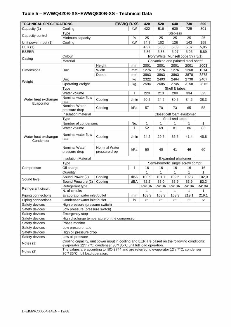
Table 5 – EWWQ420B-XS~EWWQ800B-XS - Technical Data TECHNICAL SPECIFICATIONS EWWQ B-XS 420 520 640 730 800 Capacity (1) Cooling kW 422 516 639 725 801
Capacity control Type Stepless Minimum capacity % 25 25 25 25 25
Unit power input (1) Cooling kW 84,9 102 126 143 159 EER (1) 4,97 5,03 5,09 5,07 5,05 ESEER 5,86 5,88 5,97 5,95 5,89
Casing Colour Ivory White (Munsell code 5Y7.5/1) Material Galvanized and painted steel sheet
Dimensions Unit Height mm 2001 2001 2001 2001 2003 Width mm 1276 1276 1276 1268 1314 Depth mm 3863 3863 3863 3878 3878
Weight Unit kg 2322 2403 2464 2738 2407 Operating Weight kg 2594 2685 2745 3158 2815
Water heat exchanger Evaporator
Type Shell & tubes Water volume l 220 213 200 334 325 Nominal water flow rate Cooling l/min 20,2 24,6 30,5 34,6 38,3
Nominal Water pressure drop
Cooling kPa 57 70 73 65 58
Insulation material Closet cell foam elastomer
Water heat exchanger Condenser
Type Shell and tubes Number of condensers No. 1 1 1 1 1 Water volume l 52 69 81 86 83
Nominal water flow rate Cooling l/min 24,2 29,5 36,5 41,4 45,8
Nominal Water pressure drop
Nominal Water pressure drop kPa 50 40 41 46 60
Insulation Material Expanded elastomer
Compressor Type Semi-hermetic single screw compr. Oil charge l 16 16 16 16 16 Quantity 1 1 1 1 1
Sound level Sound Power (2) Cooling dBA 100,9 101,7 102,6 102,7 102,0 Sound Pressure (2) Cooling dBA 82,2 83,0 83,9 83,9 83,2
Refrigerant circuit Refrigerant type R410A R410A R410A R410A R410A N. of circuits 1 1 1 1 1
Piping connections Evaporator water inlet/outlet mm 168,3 168,3 168,3 219.1 219.1 Piping connections Condenser water inlet/outlet in 8” 8” 8” 6” 6” Safety devices High pressure (pressure switch) Safety devices Low pressure (pressure switch) Safety devices Emergency stop Safety devices High discharge temperature on the compressor Safety devices Phase monitor Safety devices Low pressure ratio Safety devices High oil pressure drop Safety devices Low oil pressure
Notes (1) Cooling capacity, unit power input in cooling and EER are based on the following conditions: evaporator 12°/ 7°C; condenser 30°/ 35°C unit full load operation.
Notes (2) The values are according to ISO 3744 and are referred to evaporator 12°/ 7°C, condenser 30°/ 35°C, full load operation.

D–EIMWC00504-14EN - 13/68
Table 6 – EWWQ970B-XS~EWWQC13B-XS - Technical Data TECHNICAL SPECIFICATIONS EWWQ B-XS 970 C10 C11 C12 C13 Capacity (1) Cooling kW 973 1037 1118 1158 1270
Capacity control Type Stepless Minimum capacity % 25 12,5 25 12,5 12,5
Unit power input (1) Cooling kW 193 205 227 228 252 EER (1) 5,05 5,06 4,91 5,07 5,04 ESEER 5,66 6,18 5,54 6,13 6,13
Casing Colour Ivory White (Munsell code 5Y7.5/1) Material Galvanized and painted steel sheet
Dimensions Unit Height mm 2003 2454 2003 2454 2454 Width mm 1448 1350 1448 1350 1350 Depth mm 3919 5219 3919 5219 5219
Weight Unit kg 2427 4775 2457 4831 4873 Operating Weight kg 3056 5431 3086 5479 5512
Water heat exchanger Evaporator
Type Shell & tubes Water volume l 538 587 538 575 563 Nominal water flow rate Cooling l/min 46,5 49,6 53,3 55,3 60,7
Nominal Water pressure drop
Cooling kPa 55 55 70 65 56
Insulation material Closet cell foam elastomer
Water heat exchanger Condenser
Type Shell & tubes Number of condensers No. 1 2 1 2 2
Water volume l 91 1) 69
2) 70
91 1) 73
2) 76
1) 76
2) 76
Nominal water flow rate Cooling l/min 55,7
1) 29,5
2) 29,5 64,2
1) 29,6
2) 36,3
1) 36,3
2) 36,3
Nominal Water pressure drop
Nominal Water pressure drop kPa 64
1) 39
2) 39 84
1) 35
2) 48
1) 48
2) 48
Insulation Material Expanded elastomer
Compressor Type Semi-hermetic single screw compressor Oil charge l 16 32 16 32 32 Quantity 1 2 1 2 2
Sound level Sound Power (2) Cooling dBA 102,9 105,2 103,8 105,6 106,1 Sound Pressure (2) Cooling dBA 84,0 85,6 84,9 86,0 86,5
Refrigerant circuit Refrigerant type R410A R410A R410A R410A R410A N. of circuits 1 2 1 2 2
Piping connections Evaporator water inlet/outlet mm 273 219,1 273 219,1 219,1 Piping connections Condenser water inlet/outlet in 6” 5” 6” 5” 5” Safety devices High pressure (pressure switch) Safety devices Low pressure (pressure switch) Safety devices Emergency stop Safety devices High discharge temperature on the compressor Safety devices Phase monitor Safety devices Low pressure ratio Safety devices High oil pressure drop Safety devices Low oil pressure
Notes (1) Cooling capacity, unit power input in cooling and EER are based on the following conditions: evaporator 12°/ 7°C; condenser 30°/ 35°C unit full load operation.
Notes (2) The values are according to ISO 3744 and are referred to evaporator 12°/ 7°C, condenser 30°/ 35°C, full load operation.
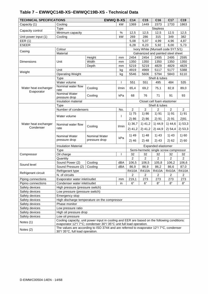
D-EIMWC00504-14EN - 14/68
Table 7 – EWWQC14B-XS~EWWQC19B-XS - Technical Data TECHNICAL SPECIFICATIONS EWWQ B-XS C14 C15 C16 C17 C19 Capacity (1) Cooling kW 1369 1449 1573 1733 1863
Capacity control Type Stepless Minimum capacity % 12,5 12,5 12,5 12,5 12,5
Unit power input (1) Cooling kW 269 286 315 349 382 EER (1) 5,08 5,07 4,99 4,96 4,87 ESEER 6,28 6,23 5,92 6,00 5,73
Casing Colour Ivory White (Munsell code 5Y7.5/1) Material Galvanized and painted steel sheet
Dimensions Unit Height mm 2454 2454 2495 2495 2595 Width mm 1350 1350 1350 1350 1350 Depth mm 5219 5219 4829 4829 4829
Weight Unit kg 4919 4969 5117 5177 5388 Operating Weight kg 5546 5606 5794 5843 6110
Water heat exchanger Evaporator
Type Shell & tubes Water volume l 551 551 495 484 535 Nominal water flow rate Cooling l/min 65,4 69,2 75,1 82,8 89,0
Nominal Water pressure drop Cooling kPa 68 76 71 91 93
Insulation material Closet cell foam elastomer
Water heat exchanger Condenser
Type Shell & tubes Number of condensers No. 2 2 2 2 2
Water volume l 1) 75
2) 86
1) 86
2) 86
1) 91
2) 91
1) 91
2) 91
1) 91
2)91
Nominal water flow rate Cooling l/min
1) 36,7
2) 41,2
1) 41,2
2) 41,2
1) 44,9
2) 44,9
1) 44,6
2) 54,4
1) 53,3
2) 53,3
Nominal Water pressure drop
Nominal Water pressure drop kPa
1) 49
2) 46
1) 48
2) 48
1) 43
2) 43
1) 43
2) 62
1) 60
2) 60
Insulation Material Expanded elastomer
Compressor Type Semi-hermetic single screw compressor Oil charge l 32 32 32 32 32 Quantity 2 2 2 2 2
Sound level Sound Power (2) Cooling dBA 106,5 106,5 105,8 106,2 106,6 Sound Pressure (2) Cooling dBA 86,9 86,9 86,2 86,6 87,0
Refrigerant circuit Refrigerant type R410A R410A R410A R410A R410A N. of circuits 2 2 2 2 2
Piping connections Evaporator water inlet/outlet mm 219,1 273 273 273 273 Pipino connections Condenser water inlet/outlet in 6” 6” 8” 8” 8” Safety devices High pressure (pressure switch) Safety devices Low pressure (pressure switch) Safety devices Emergency stop Safety devices High discharge temperature on the compressor Safety devices Phase monitor Safety devices Low pressure ratio Safety devices High oil pressure drop Safety devices Low oil pressure
Notes (1) Cooling capacity, unit power input in cooling and EER are based on the following conditions: evaporator 12°/ 7°C; condenser 30°/ 35°C unit full load operation.
Notes (2) The values are according to ISO 3744 and are referred to evaporator 12°/ 7°C, condenser 30°/ 35°C, full load operation.

D–EIMWC00504-14EN - 15/68
Table 8 – EWWQC20B-XS-EWWQC21B-XS - Technical Data TECHNICAL SPECIFICATIONS EWWQ B-XS C20 C21 Capacity (1) Cooling kW 2020 2152
Capacity control Type Stepless Minimum capacity % 12.5 12.5
Unit power input (1) Cooling kW 417 451 EER (1) 4,84 4,77 ESEER 5,78 5,64
Casing Colour Ivory White (Munsell code 5Y7.5/1) Material Galvanized and painted steel sheet
Dimensions Unit Height mm 2495 2495 Width mm 1350 1350 Depth mm 4865 4865
Weight Unit kg 5408 5414 Operating Weight kg 6118 6124
Water heat exchanger Evaporator
Type Shell & tubes Water volume l 527 527 Nominal water flow rate Cooling l/min 96,5 103
Nominal Water pressure drop Cooling kPa 115 129
Insulation material Closet cell foam elastomer
Water heat exchanger Condenser
Type Shell & tubes Number of condensers No. 2 2
Water volume l 1) 91
2) 91
1) 91
2) 91
Nominal water flow rate Cooling l/min
1) 53,2
2) 62,6
1) 61,9
2) 61,9
Nominal Water pressure drop
Nominal Water pressure drop kPa
1) 52
2) 79
1) 78
2) 78
Insulation Material Expanded elastomer
Compressor Type Semi-hermet. single screw compr. Oil charge l 32 32 Quantity 2 2
Sound level Sound Power (2) Cooling dBA 107,1 107,5 Sound Pressure (2) Cooling dBA 87,5 87,9
Refrigerant circuit Refrigerant type R410A R410A N. of circuits 2 2
Piping connections Evaporator water inlet/outlet mm 273 273 Piping connections Condenseer water inlet/outlet in 8” 8” Safety devices High pressure (pressure switch) Safety devices Low pressure (pressure switch) Safety devices Emergency stop Safety devices High discharge temperature on the compressor Safety devices Phase monitor Safety devices Low pressure ratio Safety devices High oil pressure drop Safety devices Low oil pressure
Notes (1) Cooling capacity, unit power input in cooling and EER are based on the following conditions: evaporator 12°/ 7°C; condenser 30°/ 35°C unit full load operation.
Notes (2) The values are according to ISO 3744 and are referred to evaporator 12°/ 7°C, condenser 30°/ 35°C, full load operation.

D-EIMWC00504-14EN - 16/68
Table 9 - Sound levels EWWQ B-SS
Size Sound pressure level at 1 m from the unit in free f ield (ref. 2 x 10⁻⁵) 63 Hz 125 Hz 250 Hz 500 Hz 1000 Hz 2000 Hz 4000 Hz 8000 Hz dBA
380 55.1 59.4 71.6 84.1 71.9 72.5 58.5 53.2 82.2 460 55.9 60.2 72.4 84.9 72.7 73.3 59.3 54.0 83.0 560 56.8 61.1 73.3 85.8 73.6 74.2 60.2 54.9 83.9 640 56.8 61.1 73.3 85.8 73.6 74.2 60.2 54.9 83.9 730 56,1 60,4 72,6 85,1 72,9 73,5 59,5 54,2 83,2 860 56,9 61,2 73,4 85,9 73,7 74,3 60,3 55,0 84,0 C10 57,8 62,1 74,3 86,8 74,6 75,2 61,2 55,9 84,9 800 58.1 62.4 74.6 87.1 74.9 75.5 61.5 56.2 85.2 870 58.1 62.4 74.6 87.1 74.9 75.5 61.5 56.2 85.2 960 58.5 62.8 75.0 87.5 75.3 75.9 61.9 56.6 85.6 C11 58.9 63.2 75.4 87.9 75.7 76.3 62.3 57.0 86.0 C12 59.4 63.7 75.9 88.4 76.2 76.8 62.8 57.5 86.5 C13 59.8 64.1 76.3 88.8 76.6 77.2 63.2 57.9 86.9 C14 59.8 64.1 76.3 88.8 76.6 77.2 63.2 57.9 86.9 C15 59,1 63,4 75,6 88,1 75,9 76,5 62,5 57,2 86,2 C16 59,5 63,8 76,0 88,5 76,3 76,9 62,9 57,6 86,6 C17 59,9 64,2 76,4 88,9 76,7 77,3 63,3 58,0 87,0 C19 60,4 64,7 76,9 89,4 77,2 77,8 63,8 58,5 87,5 C20 60,8 65,1 77,3 89,8 77,6 78,2 64,2 58,9 87,9
Note: The values are according to ISO 3744
Table 10 - Sound levels EWWQ B-XS
Size Sound pressure level at 1 m from the unit in free f ield (ref. 2 x 10⁻⁵) 63 Hz 125 Hz 250 Hz 500 Hz 1000 Hz 2000 Hz 4000 Hz 8000 Hz dBA
420 55.1 59.4 71.6 84.1 71.9 72.5 58.5 53.2 82.2 520 55.9 60.2 72.4 84.9 72.7 73.3 59.3 54.0 83.0 640 56.8 61.1 73.3 85.8 73.6 74.2 60.2 54.9 83.9 730 56.8 61.1 73.3 85.8 73.6 74.2 60.2 54.9 83.9 800 56,1 60,4 72,6 85,1 72,9 73,5 59,5 54,2 83,2 970 56,9 61,2 73,4 85,9 73,7 74,3 60,3 55,0 84,0 C10 58.5 62.8 75 87.5 75.3 75.9 61.9 56.6 85.6 C11 57,8 62,1 74,3 86,8 74,6 75,2 61,2 55,9 84,9 C12 58.9 63.2 75.4 87.9 75.7 76.3 62.3 57.0 86.0 C13 59.4 63.7 75.9 88.4 76.2 76.8 62.8 57.5 86.5 C14 59.8 64.1 76.3 88.8 76.6 77.2 63.2 57.9 86.9 C15 59.8 64.1 76.3 88.8 76.6 77.2 63.2 57.9 86.9 C16 59,1 63,4 75,6 88,1 75,9 76,5 62,5 57,2 86,2 C17 59,5 63,8 76,0 88,5 76,3 76,9 62,9 57,6 86,6 C19 59,9 64,2 76,4 88,9 76,7 77,3 63,3 58,0 87,0 C20 60,4 64,7 76,9 89,4 77,2 77,8 63,8 58,5 87,5 C21 60,8 65,1 77,3 89,8 77,6 78,2 64,2 58,9 87,9
Note: The values are according to ISO 3744
D–EIMWC00504-14EN - 17/68
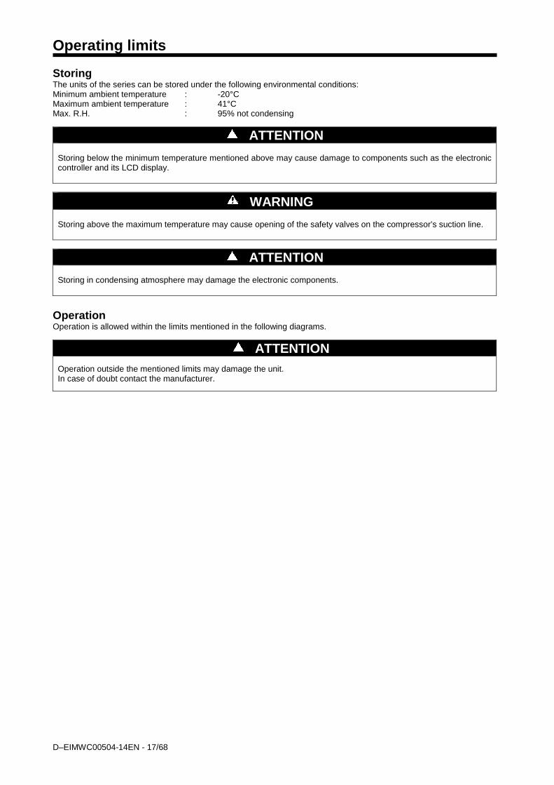
Operating limits Storing The units of the series can be stored under the following environmental conditions: Minimum ambient temperature : -20°C Maximum ambient temperature : 41°C Max. R.H. : 95% not condensing
ATTENTION Storing below the minimum temperature mentioned above may cause damage to components such as the electronic controller and its LCD display.
WARNING Storing above the maximum temperature may cause opening of the safety valves on the compressor’s suction line.
ATTENTION Storing in condensing atmosphere may damage the electronic components.
Operation Operation is allowed within the limits mentioned in the following diagrams.
ATTENTION Operation outside the mentioned limits may damage the unit. In case of doubt contact the manufacturer.

D-EIMWC00504-14EN - 18/68
20,021,022,023,024,025,026,027,028,029,030,031,032,033,034,035,036,037,038,039,040,041,042,043,044,045,046,047,048,0
-6,0 -5,0 -4,0 -3,0 -2,0 -1,0 0,0 1,0 2,0 3,0 4,0 5,0 6,0 7,0 8,0 9,0 10,0 11,0
Con
dens
er le
avin
g w
ater
tem
pera
ture
in °
C
Evaporator leaving water temperature in °C
Operating limits - EWWQ - AJYNN / EWWQ - AJYNN/A
Glycol must be used
Check on rating tables for actual operating limit at full load for SE ST machines with FR4 compressor.
Fig. 1 – Operating limit
Mechanical Installation
Check on rating tables for actual operating limit at full load for EWWQ B-SS machines with Fr4 compressor
EWWQ B-SS~EWWQ B-XS
D–EIMWC00504-14EN - 19/68
Shipping The stability of the machine during shipping must be ensured. If the machine is shipped with a wooden cross-plank on its base, the cross-plank must be removed only after the final destination has been reached.
Responsibility The manufacturer declines all responsibility, present and future, for any damage to persons, animals or property caused by negligence of operators failing to follow the installation and maintenance instructions in this manual. All safety equipment must be regularly and periodically checked in accordance with this manual and with local laws and regulations regarding safety and environment protection.
Safety The machine must be firmly secured to the ground. It is essential to observe the following instructions: - The machine can only be lifted using the lifting points on the base of the machine itself. These are the only points that
can support the entire weight of the unit. - Do not allow unauthorised and/or unqualified personnel to access the machine. - It is forbidden to access the electrical components without having opened the machine's general disconnecting switch
and switched off the power supply. - It is forbidden to access the electrical components without using an insulating platform. Do not access the electrical
components if water and/or moisture are present. - All operations on the refrigerant circuit and on components under pressure must be carried out by qualified personnel
only. - Replacement of a compressor or addition of lubricating oil must be carried out by qualified personnel only. - Sharp edges can cause wounds. Avoid direct contact. - Avoid introducing solid bodies into the water pipes while the machine is connected to the system. - A mechanical filter must be installed on the water pipe connected to the heat exchanger inlet. - The machine is supplied with safety valves, that are installed on both the high and the low pressure sides of the
refrigerant circuit. In case of sudden stop of the unit, follow the instructions on the Control Panel Operating Manual which is part of the on-board documentation delivered to the end user with this manual. It is recommended to perform installation and maintenance with other people. In case of accidental injury or unease, it is necessary to: - keep calm - press the alarm button if present in the installation site - move the injured person in a warm place far from the unit and in rest position - contact immediately emergency rescue personnel of the building or if the Health Emergency Service - wait without leaving the injured person alone until the rescue operators come - give all necessary information to the the rescue operators
WARNING Before carrying out any operation on the machine, please read this instruction and operating manual carefully. Installation and maintenance must be carried out only by qualified personnel that is familiar with the provisions of law and local regulations and has been trained properly or has experience with this type of equipment.
WARNING Avoid installing the machine in a place that could be dangerous during maintenance operations, such as (but not only) platforms without parapets or railings or areas not complying with the clearance requirements.
Moving and lifting Avoid bumping and/or jolting during unloading from the lorry and moving the machine. Do not push or pull the machine from any part other than the base frame. Secure the machine inside the lorry to prevent it from moving and causing damage to the panels and to the base frame. Do not allow any part of the machine to fall during transportation and/or unloading, as this could cause serious damage. All units of the series are supplied with four lifting points. Only these points may be used for lifting the unit, as shown in figure 2.

D-EIMWC00504-14EN - 20/68
Fig. 2 - Lifting the unit
WARNING Both the lifting ropes and the spacing bar and/or scales must be strong enough to support the machine safely. Please check the unit’s weight on the machine’s nameplate. The weights shown in the "Technical data" tables in the "General Information" chapter refer to standard units. Some specific machines might have accessories that increase their overall weight (heat recovery, etc.)
WARNING The machine must be lifted with the utmost attention and care. Avoid jolting when lifting and lift the machine very slowly, keeping it perfectly level.
Positioning and assembly All units are designed for installation indoors. The machine must be installed on a robust and perfectly level foundation; should the machine be installed on balconies or roofs, it might be necessary to use weight distribution beams. For installation on the ground, prepare a strong cement base that is at least 250 mm wider and longer than the machine. Also, this base must be strong enough to support the weight of the machine as stated in the technical specifications. If the machine is installed in places that are easily accessible to people and animals, it is advisable to install protection gratings for the compressor section. To ensure the best possible performance on the installation site, the following precautions and instructions must be followed: • Make sure to provide a strong and solid foundation to reduce noise and vibration as much as possible.
D–EIMWC00504-14EN - 21/68
• The water in the system must be particularly clean and all traces of oil or rust must be removed. A mechanical water filter must be installed on the machine’s inlet piping.
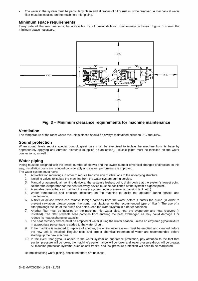
Minimum space requirements Every side of the machine must be accessible for all post-installation maintenance activities. Figure 3 shows the minimum space necessary.
Fig. 3 – Minimum clearance requirements for machine maintenance Ventilation The temperature of the room where the unit is placed should be always maintained between 0°C and 40°C.
Sound protection When sound levels require special control, great care must be exercised to isolate the machine from its base by appropriately applying anti-vibration elements (supplied as an option). Flexible joints must be installed on the water connections, as well.
Water piping Piping must be designed with the lowest number of elbows and the lowest number of vertical changes of direction. In this way, installation costs are reduced considerably and system performance is improved. The water system must have:
1. Anti-vibration mountings in order to reduce transmission of vibrations to the underlying structure. 2. Isolating valves to isolate the machine from the water system during service. 3. Manual or automatic air venting device at the system’s highest point; drain device at the system’s lowest point.
Neither the evaporator nor the heat recovery device must be positioned at the system’s highest point. 4. A suitable device that can maintain the water system under pressure (expansion tank, etc.) 5. Water temperature and pressure indicators on the machine to assist the operator during service and
maintenance. 6. A filter or device which can remove foreign particles from the water before it enters the pump (in order to
prevent cavitation, please consult the pump manufacturer for the recommended type of filter ). The use of a filter prolongs the life of the pump and helps keep the water system in a better condition.
7. Another filter must be installed on the machine inlet water pipe, near the evaporator and heat recovery (if installed). The filter prevents solid particles from entering the heat exchanger, as they could damage it or reduce its heat exchanging capacity.
8. The heat recovery device must be emptied of water during the winter season, unless an ethylenic glycol mixture in appropriate percentage is added to the water circuit.
9. If the machine is intended to replace of another, the entire water system must be emptied and cleaned before the new unit is installed. Regular tests and proper chemical treatment of water are recommended before starting up the new machine.
10. In the event that glycol is added to the water system as anti-freeze protection, pay attention to the fact that suction pressure will be lower, the machine’s performance will be lower and water pressure drops will be greater. All machine-protection systems, such as anti-freeze, and low-pressure protection will need to be readjusted.
Before insulating water piping, check that there are no leaks.
D-EIMWC00504-14EN - 22/68
Fig. 4 – Water piping connection for heat recovery exchangers
D–EIMWC00504-14EN - 23/68
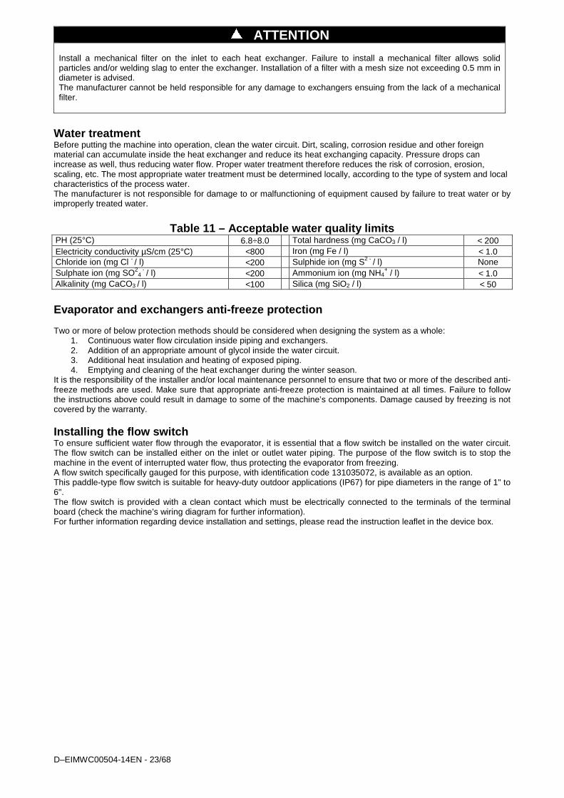
ATTENTION Install a mechanical filter on the inlet to each heat exchanger. Failure to install a mechanical filter allows solid particles and/or welding slag to enter the exchanger. Installation of a filter with a mesh size not exceeding 0.5 mm in diameter is advised. The manufacturer cannot be held responsible for any damage to exchangers ensuing from the lack of a mechanical filter.
Water treatment Before putting the machine into operation, clean the water circuit. Dirt, scaling, corrosion residue and other foreign material can accumulate inside the heat exchanger and reduce its heat exchanging capacity. Pressure drops can increase as well, thus reducing water flow. Proper water treatment therefore reduces the risk of corrosion, erosion, scaling, etc. The most appropriate water treatment must be determined locally, according to the type of system and local characteristics of the process water. The manufacturer is not responsible for damage to or malfunctioning of equipment caused by failure to treat water or by improperly treated water.
Table 11 – Acceptable water quality limits
PH (25°C) 6.8÷8.0 Total hardness (mg CaCO3 / l) < 200 Electricity conductivity µS/cm (25°C) <800 Iron (mg Fe / l) < 1.0 Chloride ion (mg Cl - / l) <200 Sulphide ion (mg S2 - / l) None Sulphate ion (mg SO2
4 - / l) <200 Ammonium ion (mg NH4
+ / l) < 1.0 Alkalinity (mg CaCO3 / l) <100 Silica (mg SiO2 / l) < 50
Evaporator and exchangers anti-freeze protection Two or more of below protection methods should be considered when designing the system as a whole:
1. Continuous water flow circulation inside piping and exchangers. 2. Addition of an appropriate amount of glycol inside the water circuit. 3. Additional heat insulation and heating of exposed piping. 4. Emptying and cleaning of the heat exchanger during the winter season.
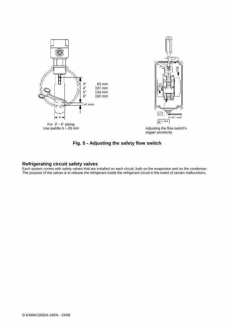
It is the responsibility of the installer and/or local maintenance personnel to ensure that two or more of the described anti-freeze methods are used. Make sure that appropriate anti-freeze protection is maintained at all times. Failure to follow the instructions above could result in damage to some of the machine’s components. Damage caused by freezing is not covered by the warranty. Installing the flow switch To ensure sufficient water flow through the evaporator, it is essential that a flow switch be installed on the water circuit. The flow switch can be installed either on the inlet or outlet water piping. The purpose of the flow switch is to stop the machine in the event of interrupted water flow, thus protecting the evaporator from freezing. A flow switch specifically gauged for this purpose, with identification code 131035072, is available as an option. This paddle-type flow switch is suitable for heavy-duty outdoor applications (IP67) for pipe diameters in the range of 1" to 6". The flow switch is provided with a clean contact which must be electrically connected to the terminals of the terminal board (check the machine’s wiring diagram for further information). For further information regarding device installation and settings, please read the instruction leaflet in the device box.
D-EIMWC00504-14EN - 24/68
Fig. 5 - Adjusting the safety flow switch
Refrigerating circuit safety valves Each system comes with safety valves that are installed on each circuit, both on the evaporator and on the condenser. The purpose of the valves is to release the refrigerant inside the refrigerant circuit in the event of certain malfunctions.
3” 83 mm 4” 107 mm 5” 134 mm 6” 162 mm
>5 mm
For 3” - 6” piping Use paddle b = 29 mm Adjusting the flow switch’s
trigger sensitivity
D–EIMWC00504-14EN - 25/68
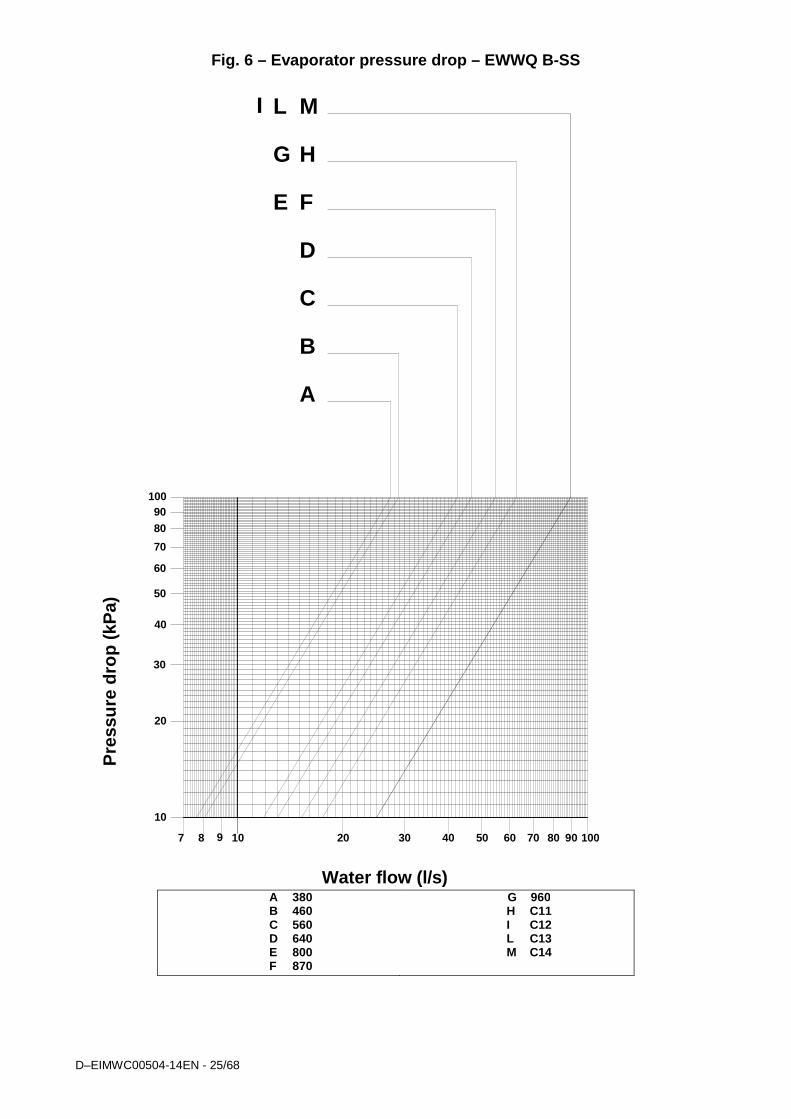
Fig. 6 – Evaporator pressure drop – EWWQ B-SS
Pre
ssur
e dr
op (
kPa)
A
B
C
D
E F
G H
10 10020 30 40 50 60 70 80 90
Water flow (l/s)
87
10
100
20
30
40
50
60
70
8090
I L M
9
A 380 B 460 C 560 D 640 E 800 F 870
G 960 H C11 I C12 L C13 M C14

D-EIMWC00504-14EN - 26/68
Fig. 7 – Evaporator pressure drop – EWWQ B-SS
Pre
ssur
e dr
op (
kPa)
ABC
D E
FG
H
10 10020 30 40 50 60 70 80 90
Water flow (l/s)
10
100
20
30
40
50
60
70
8090
A. 730 B. 860 C. C10 D. C15
E. C16 F. C17 G. C19 H. C20

D–EIMWC00504-14EN - 27/68
Fig. 8 – Evaporator pressure drop - EWWQ B-XS
Pre
ssur
e dr
op (
kPa)
ABCDEF
GH
10 10020 30 40 50 60 70 80 90
Water flow (l/s)
10
100
20
30
40
50
60
70
8090
I
7 8 9
A. 420 B. 520 C. 640 D. 730 E. C10
F. C12 G. C13 H. C14 I. C15
D-EIMWC00504-14EN - 28/68
Fig. 9 – Evaporator pressure drop - EWWQ B-XS
Pre
ssur
e dr
op (
kPa)
AB C
D
E
F
G H
10 10020 30 40 50 60 70 80 90
Water flow (l/s)
10
100
20
30
40
50
60
70
8090
A. 800 B. 970 C. C11 D. C16
E. C17 F. C19 G. C20 H. C21
D–EIMWC00504-14EN - 29/68
Fig. 10 – Condenser pressure drop - EWWQ B-SS
70
10 20
20
40
ABCDEFGHILM
8 1009 30 40 50 60 70 80 90
80
60
50
90
10
30
100
Water flow (l/s)
Pre
ssur
e dr
op (
kPa)
A. 380 B. 460 C. 560 D. 640 E. 800 F. 870
G. 960 H. C11 I. C12 L. C13 M. C14

D-EIMWC00504-14EN - 30/68
Fig. 11 – Condenser pressure drop - EWWQ B-SS
ABC
D EFGH
10
100
20
30
40
50
60
70
8090
400100 50030 40 50 60 70 80 90 200
Water flow (l/s)
300
Pre
ssur
e dr
op (
kPa)
A. 730 B. 860 C. C10 D. C15
E. C16 F. C17 G. C19 H. C20

D–EIMWC00504-14EN - 31/68
Fig. 12 – Condenser pressure drop - EWWQ B-XS
ABCDEFGHI
10
100
20
30
40
50
60
70
80
90
10 10020 30 40 50 60 70 80 90 200
Water flow (l/s)
Pre
ssur
e dr
op (
kPa)
A. 420 B. 520 C. 640 D. 730 E. C10
F. C12 G. C13 H. C14 I. C15
D-EIMWC00504-14EN - 32/68
Fig. 13 – Condenser pressure drop - EWWQ B-XS
10 100
A
B C
D
E
F
G
H
Water flow (l/s)
Pre
ssur
e dr
op (k
Pa)
20 30 40 50 60 70 80 90 200
10
100
20
30
40
50
60
70
80
90
A. 800 B. 970 C. C11 D. C16
E. C17 F. C19 G. C20 H. C21
D–EIMWC00504-14EN - 33/68
Fig. 14 – Partial heat recovery pressure drop - EWWQ B-SS
Pre
ssur
e dr
op (
kPa)
Water flow (l/s)
10
100
20
30
40
50
60
70
80
90
1 2 3 4 5 6 7 8 9 10
A B
C D
E G
F
H
I
0.9
L
L M
A. 380 B. 460 C. 560 D. 640 E. 800 F. 870
G. 960 H. C11 I. C12
L. C13 M. C14
D-EIMWC00504-14EN - 34/68
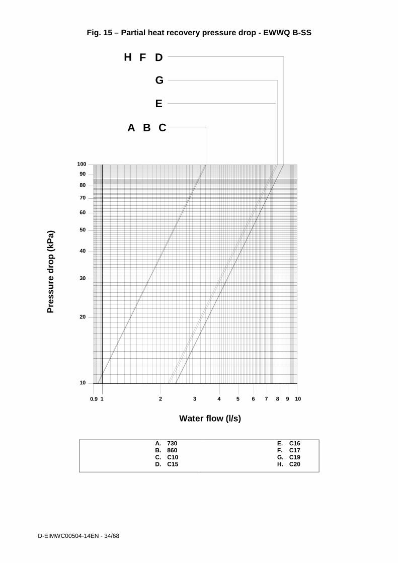
Fig. 15 – Partial heat recovery pressure drop - EWWQ B-SS
DFH
A B C
E
G
Pre
ssur
e dr
op (
kPa)
Water flow (l/s)
10
20
30
40
50
60
70
80
90
1 2 3 4 5 6 7 8 9 100.9
100
A. 730 B. 860 C. C10 D. C15
E. C16 F. C17 G. C19 H. C20
D–EIMWC00504-14EN - 35/68
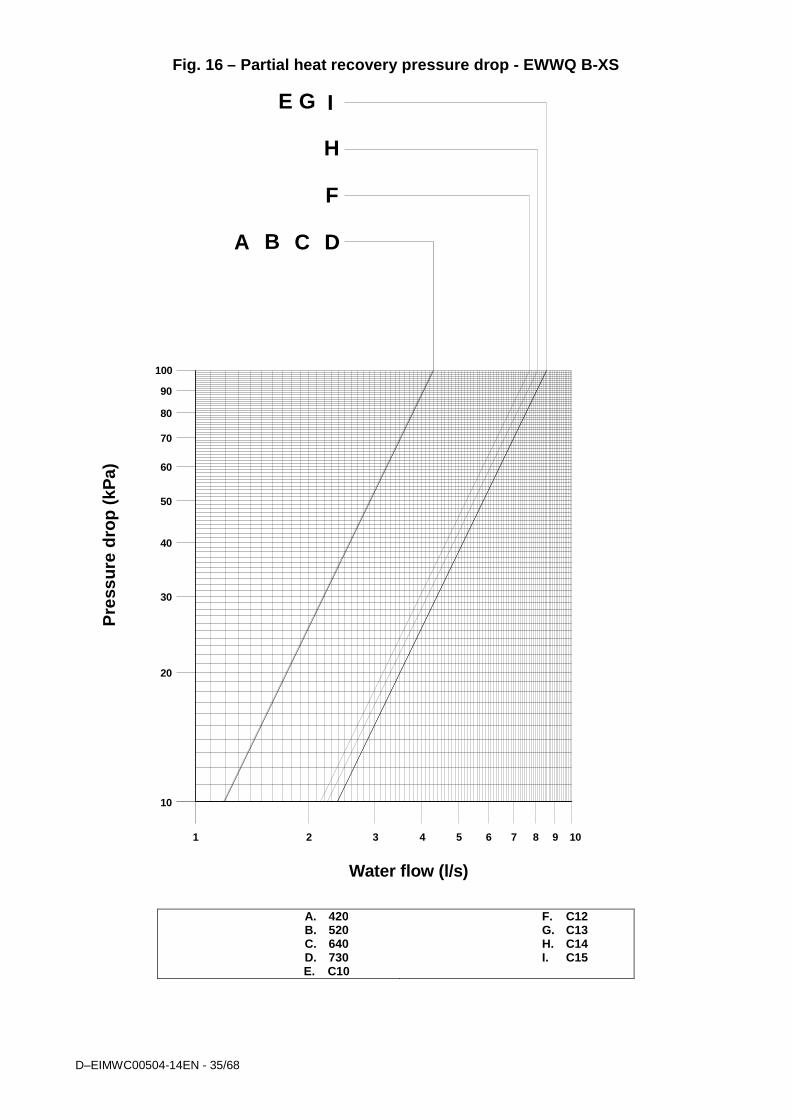
Fig. 16 – Partial heat recovery pressure drop - EWWQ B-XS
Pre
ssur
e dr
op (
kPa)
Water flow (l/s)
10
100
20
30
40
50
60
70
80
90
1 2 3 4 5 6 7 8 9 10
A B C D
E G
F
H
I
A. 420 B. 520 C. 640 D. 730 E. C10
F. C12 G. C13 H. C14 I. C15
D-EIMWC00504-14EN - 36/68
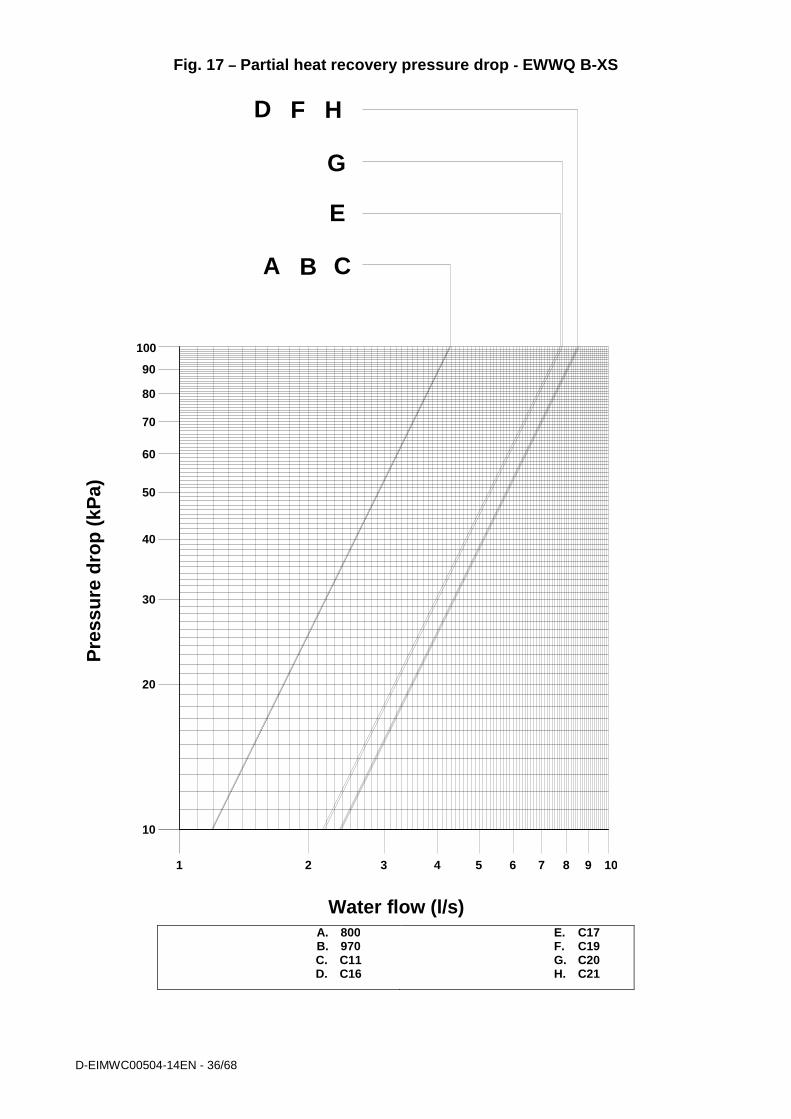
Fig. 17 – Partial heat recovery pressure drop - EWWQ B-XS
P
ress
ure
drop
(kP
a)
Water flow (l/s)
10
100
20
30
40
50
60
70
80
90
1 2 3 4 5 6 7 8 9 10
A B C
D
E
G
F H
A. 800 B. 970 C. C11 D. C16
E. C17 F. C19 G. C20 H. C21
D–EIMWC00504-14EN - 37/68
Electrical Installation General specifications
CAUTION All electrical connections to the machine must be carried out in compliance with laws and regulations in force. All installation, operating and maintenance activities must be carried out by qualified personnel. Please refer to the specific wiring diagram for the machine that you have purchased and which was sent with the unit. Should the wiring diagram not appear on the machine or should it have been lost, please contact your dealer who will provide for a copy to be forwarded.
CAUTION Use copper conductors only. Use of conductors in any material other than copper could cause overheating or corrosion at the connection points and damage the unit. To avoid interference, all control wires must be installed separately from the power cables. Use separate electrical conduits for this purpose.
CAUTION Before servicing the machine in any way, open the general disconnecting switch on the machine’s main power supply. When the machine is off but the disconnector switch is in the closed position, unused circuits are live, as well. Never open the terminal board box of the compressors before having opened the unit’s general disconnecting switch.
CAUTION Concurrence of single-phase and three-phase charges and unbalance between phases can cause leakages towards ground of up to 150 mA during the normal operation of the units of the series. If the unit includes devices that cause superior harmonics (such as VFD and phase cut), the leakage towards ground could increase to very high values (about 2 Ampere). The protections for the power supply system must be designed in accordance with the above mentioned values.
D – EIMWC00509-13EN - 38/68
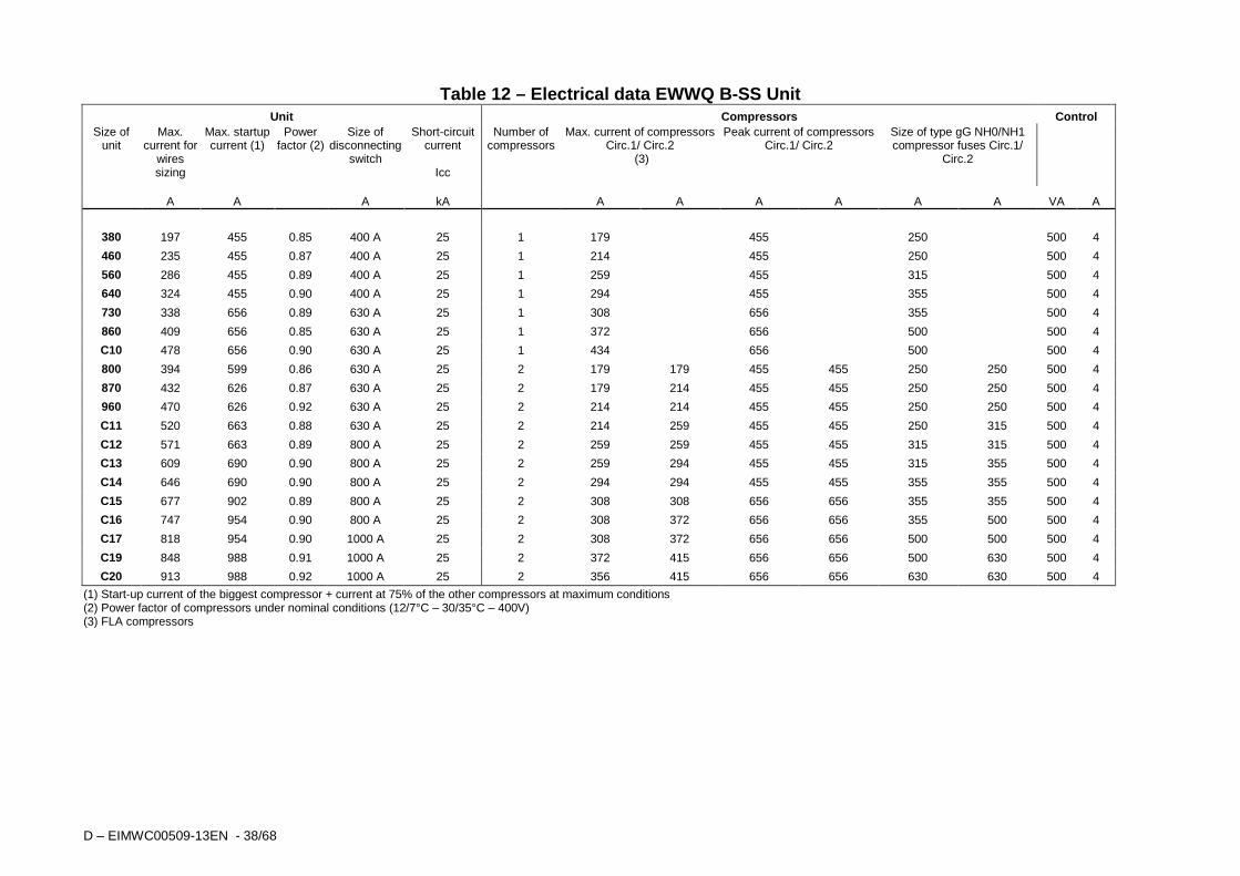
Table 12 – Electrical data EWWQ B-SS Unit Unit Compressors Control
Size of unit
Max. current for
wires sizing
Max. startup current (1)
Power factor (2)
Size of disconnecting
switch
Short-circuit current
Icc
Number of compressors
Max. current of compressors Circ.1/ Circ.2
(3)
Peak current of compressors Circ.1/ Circ.2
Size of type gG NH0/NH1 compressor fuses Circ.1/
Circ.2
A A A kA A A A A A A VA A
380 197 455 0.85 400 A 25 1 179 455 250 500 4
460 235 455 0.87 400 A 25 1 214 455 250 500 4
560 286 455 0.89 400 A 25 1 259 455 315 500 4
640 324 455 0.90 400 A 25 1 294 455 355 500 4
730 338 656 0.89 630 A 25 1 308 656 355 500 4
860 409 656 0.85 630 A 25 1 372 656 500 500 4
C10 478 656 0.90 630 A 25 1 434 656 500 500 4
800 394 599 0.86 630 A 25 2 179 179 455 455 250 250 500 4
870 432 626 0.87 630 A 25 2 179 214 455 455 250 250 500 4
960 470 626 0.92 630 A 25 2 214 214 455 455 250 250 500 4
C11 520 663 0.88 630 A 25 2 214 259 455 455 250 315 500 4
C12 571 663 0.89 800 A 25 2 259 259 455 455 315 315 500 4
C13 609 690 0.90 800 A 25 2 259 294 455 455 315 355 500 4
C14 646 690 0.90 800 A 25 2 294 294 455 455 355 355 500 4
C15 677 902 0.89 800 A 25 2 308 308 656 656 355 355 500 4
C16 747 954 0.90 800 A 25 2 308 372 656 656 355 500 500 4
C17 818 954 0.90 1000 A 25 2 308 372 656 656 500 500 500 4
C19 848 988 0.91 1000 A 25 2 372 415 656 656 500 630 500 4
C20 913 988 0.92 1000 A 25 2 356 415 656 656 630 630 500 4
(1) Start-up current of the biggest compressor + current at 75% of the other compressors at maximum conditions (2) Power factor of compressors under nominal conditions (12/7°C – 30/35°C – 400V) (3) FLA compressors
D–EIMWC00504-14EN - 39/68
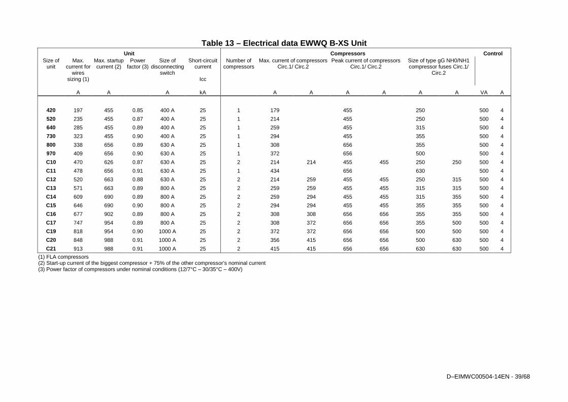
Table 13 – Electrical data EWWQ B-XS Unit Unit Compressors Control
Size of unit
Max. current for
wires sizing (1)
Max. startup current (2)
Power factor (3)
Size of disconnecting
switch
Short-circuit current
Icc
Number of compressors
Max. current of compressors Circ.1/ Circ.2
Peak current of compressors Circ.1/ Circ.2
Size of type gG NH0/NH1 compressor fuses Circ.1/
Circ.2
A A A kA A A A A A A VA A
420 197 455 0.85 400 A 25 1 179 455 250 500 4
520 235 455 0.87 400 A 25 1 214 455 250 500 4
640 285 455 0.89 400 A 25 1 259 455 315 500 4
730 323 455 0.90 400 A 25 1 294 455 355 500 4
800 338 656 0.89 630 A 25 1 308 656 355 500 4
970 409 656 0.90 630 A 25 1 372 656 500 500 4
C10 470 626 0.87 630 A 25 2 214 214 455 455 250 250 500 4
C11 478 656 0.91 630 A 25 1 434 656 630 500 4
C12 520 663 0.88 630 A 25 2 214 259 455 455 250 315 500 4
C13 571 663 0.89 800 A 25 2 259 259 455 455 315 315 500 4
C14 609 690 0.89 800 A 25 2 259 294 455 455 315 355 500 4
C15 646 690 0.90 800 A 25 2 294 294 455 455 355 355 500 4
C16 677 902 0.89 800 A 25 2 308 308 656 656 355 355 500 4
C17 747 954 0.89 800 A 25 2 308 372 656 656 355 500 500 4
C19 818 954 0.90 1000 A 25 2 372 372 656 656 500 500 500 4
C20 848 988 0.91 1000 A 25 2 356 415 656 656 500 630 500 4
C21 913 988 0.91 1000 A 25 2 415 415 656 656 630 630 500 4
(1) FLA compressors (2) Start-up current of the biggest compressor + 75% of the other compressor’s nominal current (3) Power factor of compressors under nominal conditions (12/7°C – 30/35°C – 400V)
D – EIMWC00509-13EN - 40/68
Electrical components All power and interface electrical connections are specified in the wiring diagram that is shipped with the machine. The installer must supply the following components:
- Power supply wires (dedicated conduit) - Interconnection and interface wires (dedicated conduit) - Thermal-magnetic circuit breaker of suitable size (please see electrical data).
Electrical wiring Power circuit: Connect the electrical power supply cables to the terminals of the general circuit breaker on the machine’s terminal board. The access panel must have a hole of appropriate diameter for the cable used and its cable gland. A flexible conduit can also be used, containing the three power phases plus earth. In any case, absolute protection against any water penetrating through the connection point must be ensured. Control circuit: Every machine of the series is supplied with an auxiliary 400/115V control circuit transformer. No additional cable for the control system power supply is thus required. Only if the optional separate accumulation tank is requested, the electrical anti-freeze resistance must have a separate power supply.
Electrical heaters Each circuit has an electrical heater installed in the compressor, whose purpose is to keep the oil warm thus preventing the presence of liquid refrigerant mixed with the oil in the compressor. Obviously, the operation of the electrical heaters is guaranteed only if there is a constant power supply. If it is not possible to keep the machine powered when inactive during winter, apply at least two of the procedures described in the “Mechanical Installation” section under the “Anti-freeze protection of evaporator and exchangers”. If the plant uses pumps outside the machine (not supplied with the unit), the power line of each pump must be provided with a magnetothermic switch and a control switch.
Water pump control Connect the control contactor coil power supply to terminals 27 and 28 (pump #1) and 401 and 402 (pump 2) located on terminal board M3, and install the contactor on a power supply having the same voltage as the pump contactor coil. The terminals are connected to a clean microprocessor contact. The microprocessor contact has the following commutation capacity: Maximum voltage: 250 Vac Maximum current: 2 A Resistive - 2 A Inductive Reference standard: EN 60730-1 The wiring described above allows the microprocessor to manage the water pump automatically. It is good practice to install a clean status contact pump’s thermal-magnetic circuit breaker and to connect it in series with the flow switch.
Alarm relays – Electrical wiring The machine has a clean-contact digital output that changes state whenever an alarm occurs in one of the refrigerant circuits. Connect this signal to an external visual, sound alarm or to the BMS in order to monitor its operation. See the machine’s wiring diagram for wiring. Unit On/Off remote control – Electrical wiring The machine has a digital input that allows remote control. A startup timer, a circuit breaker or a BMS can be connected to this input. Once the contact has been closed, the microprocessor launches the startup sequence by first turning on the water pump and then the compressors. When the contact is opened the microprocessor launches the machine shutdown sequence. The contact must be clean.
Double Setpoint – Electrical wiring The Double Setpoint function allows to change over the unit setpoint between two predefined values in the unit controller. An example of an application is ice production during the night and standard operation during the day. Connect a circuit breaker or timer between terminals 5 and 21 of terminal board M3. The contact must be clean.
External water Setpoint reset – Electrical wiring ( Optional) The machine’s local setpoint can be modified by means of an external analogue 4-20 mA signal. Once this function has been enabled, the microprocessor allows to modify the setpoint from the set local value up to a differential of 3°C. 4 mA corresponds to a 0°C differential, 20 mA corresponds to the setpoint plus the maximum differential. The signal cable must be directly connected to terminals 35 and 36 of the M3 terminal board. The signal cable must be of the shielded type and must not be laid in the vicinity of the power cables, so as not to induce interference with the electronic controller.
D–EIMWC00504-14EN - 41/68
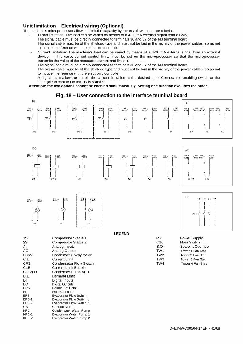
Unit limitation – Electrical wiring (Optional) The machine’s microprocessor allows to limit the capacity by means of two separate criteria:
- >Load limitation: The load can be varied by means of a 4-20 mA external signal from a BMS. The signal cable must be directly connected to terminals 36 and 37 of the M3 terminal board. The signal cable must be of the shielded type and must not be laid in the vicinity of the power cables, so as not to induce interference with the electronic controller.
- Current limitation: The machine’s load can be varied by means of a 4-20 mA external signal from an external device. In this case, current control limits must be set on the microprocessor so that the microprocessor transmits the value of the measured current and limits it. The signal cable must be directly connected to terminals 36 and 37 of the M3 terminal board. The signal cable must be of the shielded type and must not be laid in the vicinity of the power cables, so as not to induce interference with the electronic controller. A digital input allows to enable the current limitation at the desired time. Connect the enabling switch or the timer (clean contact) to terminals 5 and 9.
Attention: the two options cannot be enabled simult aneously. Setting one function excludes the other.
Fig. 18 – User connection to the interface terminal board
LEGEND
1S Compressor Status 1 PS Power Supply 2S Compressor Status 2 Q10 Main Switch Al Analog Inputs S.O. Setpoint Override AO Analog Output TW1 Tower 1 Fan Step C-3W Condenser 3-Way Valve TW2 Tower 2 Fan Step C.L. Current Limit TW3 Tower 3 Fan Step CFS Condensator Flow Switch TW4 Tower 4 Fan Step CLE Current Limit Enable CP-VFD Condenser Pump VFD D.L. Demand Limit DI Digital Inputs DO Digital Outputs DPS Double Set Point EF Esternal Fault EFS Evaporator Flow Switch EFS-1 Evaporator Flow Switch 1 EFS-2 Evaporator Flow Switch 2 GA General Alarm KPC Condensator Water Pump KPE-1 Evaporator Water Pump 1 KPE-2 Evaporator Water Pump 2
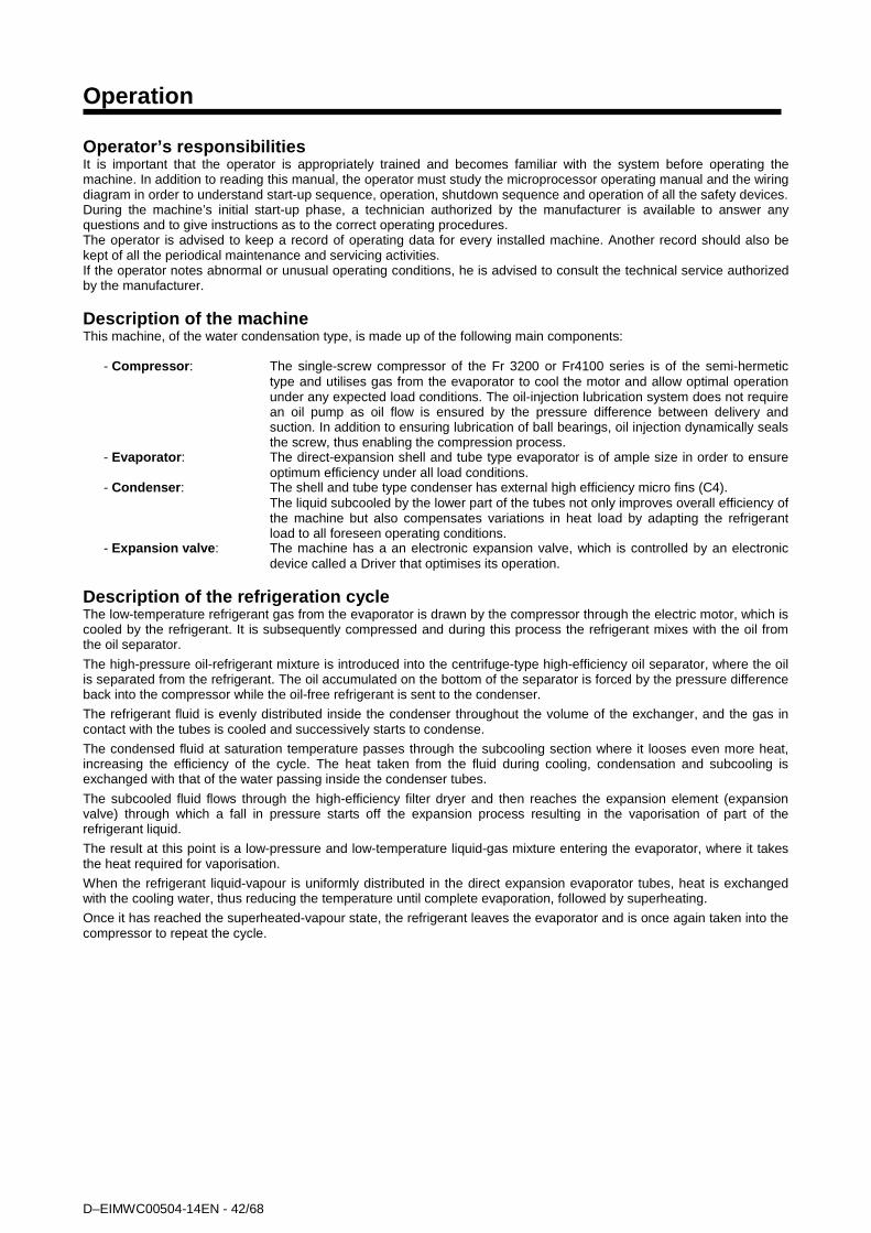
D–EIMWC00504-14EN - 42/68
Operation Operator’s responsibilities It is important that the operator is appropriately trained and becomes familiar with the system before operating the machine. In addition to reading this manual, the operator must study the microprocessor operating manual and the wiring diagram in order to understand start-up sequence, operation, shutdown sequence and operation of all the safety devices. During the machine’s initial start-up phase, a technician authorized by the manufacturer is available to answer any questions and to give instructions as to the correct operating procedures. The operator is advised to keep a record of operating data for every installed machine. Another record should also be kept of all the periodical maintenance and servicing activities. If the operator notes abnormal or unusual operating conditions, he is advised to consult the technical service authorized by the manufacturer.
Description of the machine This machine, of the water condensation type, is made up of the following main components:
- Compressor : The single-screw compressor of the Fr 3200 or Fr4100 series is of the semi-hermetic type and utilises gas from the evaporator to cool the motor and allow optimal operation under any expected load conditions. The oil-injection lubrication system does not require an oil pump as oil flow is ensured by the pressure difference between delivery and suction. In addition to ensuring lubrication of ball bearings, oil injection dynamically seals the screw, thus enabling the compression process.
- Evaporator : The direct-expansion shell and tube type evaporator is of ample size in order to ensure optimum efficiency under all load conditions.
- Condenser : The shell and tube type condenser has external high efficiency micro fins (C4). The liquid subcooled by the lower part of the tubes not only improves overall efficiency of
the machine but also compensates variations in heat load by adapting the refrigerant load to all foreseen operating conditions.
- Expansion valve : The machine has a an electronic expansion valve, which is controlled by an electronic device called a Driver that optimises its operation.
Description of the refrigeration cycle The low-temperature refrigerant gas from the evaporator is drawn by the compressor through the electric motor, which is cooled by the refrigerant. It is subsequently compressed and during this process the refrigerant mixes with the oil from the oil separator. The high-pressure oil-refrigerant mixture is introduced into the centrifuge-type high-efficiency oil separator, where the oil is separated from the refrigerant. The oil accumulated on the bottom of the separator is forced by the pressure difference back into the compressor while the oil-free refrigerant is sent to the condenser. The refrigerant fluid is evenly distributed inside the condenser throughout the volume of the exchanger, and the gas in contact with the tubes is cooled and successively starts to condense.
The condensed fluid at saturation temperature passes through the subcooling section where it looses even more heat, increasing the efficiency of the cycle. The heat taken from the fluid during cooling, condensation and subcooling is exchanged with that of the water passing inside the condenser tubes. The subcooled fluid flows through the high-efficiency filter dryer and then reaches the expansion element (expansion valve) through which a fall in pressure starts off the expansion process resulting in the vaporisation of part of the refrigerant liquid.
The result at this point is a low-pressure and low-temperature liquid-gas mixture entering the evaporator, where it takes the heat required for vaporisation.
When the refrigerant liquid-vapour is uniformly distributed in the direct expansion evaporator tubes, heat is exchanged with the cooling water, thus reducing the temperature until complete evaporation, followed by superheating.
Once it has reached the superheated-vapour state, the refrigerant leaves the evaporator and is once again taken into the compressor to repeat the cycle.

D – EIMWC00509-13EN - 43/68
W L 1S T 1
E V A P O R A T O R
W L 2S T 2
E X 8
E L E C T R O N ICE X P . V A L V E
E X 8
E L E C T R O N ICE X P . V A L V E
E V A P O R A T O RH E A T E R
W A T E RI N L E T
W A T E R
O U T L E T
Y 5
Y 6
Fig. 19 - Refrigeration cycle of the EWWQ B-SS / EW WQ B-XS DUAL Fr4 unit
LOW PRESSURE SWITCH
HIGH PRESSURE SWITCH
F12-22 LP
F13-23 HP
LOW PRESSURE TRANSDUCER (0 ÷ 30 bar)
HIGH PRESSURE TRANSDUCER (0 ÷ 45 bar)
LEAVING WATER TEMPERATURE
ENTERING WATER TEMPERATURE
WH1-2
WOE
WL1-2
WIE
OIL TEMPERATUREWD1-2
ST1-2 SUCTION TEMPERATURE
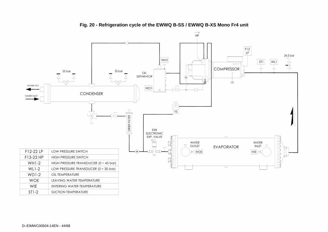
D–EIMWC00504-14EN - 44/68
Fig. 20 - Refrigeration cycle of the EWWQ B-SS / EW WQ B-XS Mono Fr4 unit
WL1ST1
EVAPORATOR
EX8
ELECTRONIC
EXP. VALVE
WATER
INLET
WATER
OUTLET
Y5
LOW PRESSURE SWITCH
HIGH PRESSURE SWITCH
F12-22 LP
F13-23 HP
LOW PRESSURE TRANSDUCER (0 ÷ 30 bar)
HIGH PRESSURE TRANSDUCER (0 ÷ 45 bar)
LEAVING WATER TEMPERATURE
ENTERING WATER TEMPERATURE
WH1-2
WOE
WL1-2
WIE
OIL TEMPERATUREWD1-2
ST1-2 SUCTION TEMPERATURE
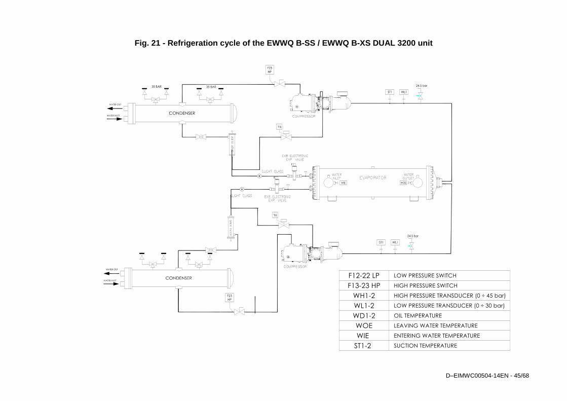
D–EIMWC00504-14EN - 45/68
Fig. 21 - Refrigeration cycle of the EWWQ B-SS / EW WQ B-XS DUAL 3200 unit
LOW PRESSURE SWITCH
HIGH PRESSURE SWITCH
F12-22 LP
F13-23 HP
LOW PRESSURE TRANSDUCER (0 ÷ 30 bar)
HIGH PRESSURE TRANSDUCER (0 ÷ 45 bar)
LEAVING WATER TEMPERATURE
ENTERING WATER TEMPERATURE
WH1-2
WOE
WL1-2
WIE
OIL TEMPERATUREWD1-2
ST1-2 SUCTION TEMPERATURE
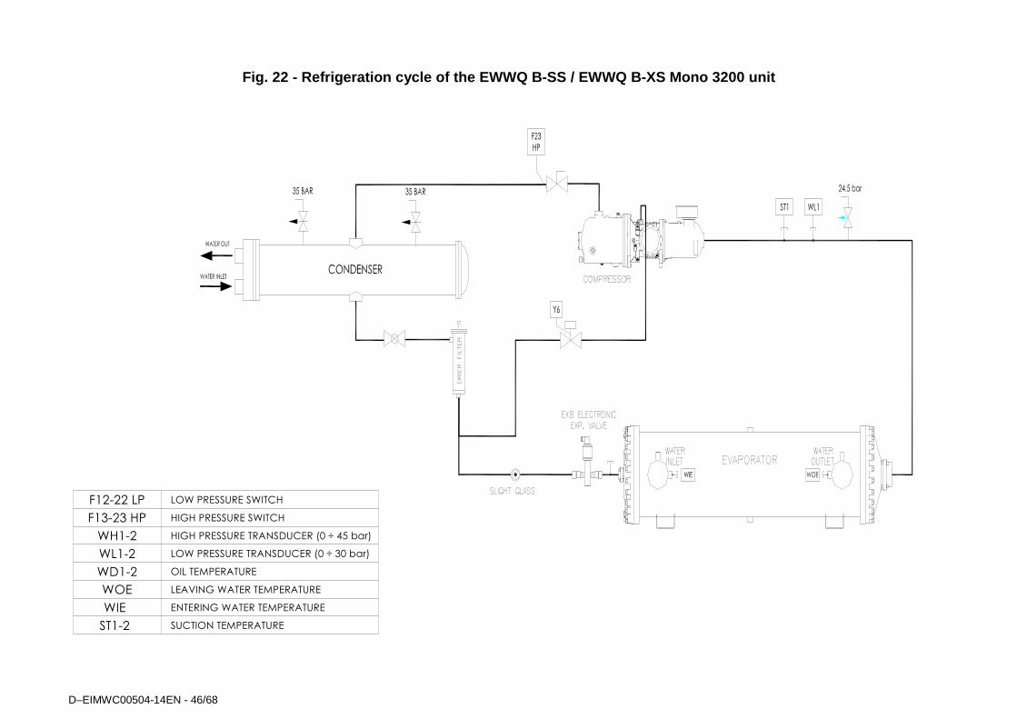
D–EIMWC00504-14EN - 46/68
Fig. 22 - Refrigeration cycle of the EWWQ B-SS / EW WQ B-XS Mono 3200 unit
LOW PRESSURE SWITCH
HIGH PRESSURE SWITCH
F12-22 LP
F13-23 HP
LOW PRESSURE TRANSDUCER (0 ÷ 30 bar)
HIGH PRESSURE TRANSDUCER (0 ÷ 45 bar)
LEAVING WATER TEMPERATURE
ENTERING WATER TEMPERATURE
WH1-2
WOE
WL1-2
WIE
OIL TEMPERATUREWD1-2
ST1-2 SUCTION TEMPERATURE
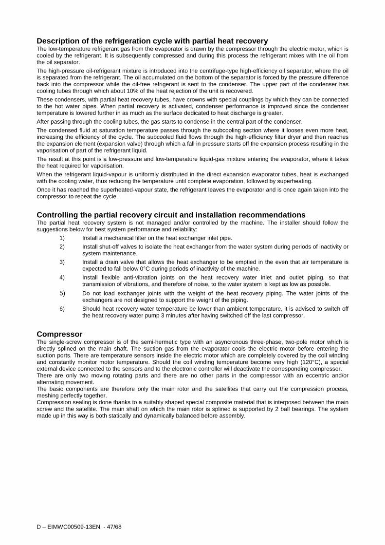
D – EIMWC00509-13EN - 47/68
Description of the refrigeration cycle with partial heat recovery The low-temperature refrigerant gas from the evaporator is drawn by the compressor through the electric motor, which is cooled by the refrigerant. It is subsequently compressed and during this process the refrigerant mixes with the oil from the oil separator. The high-pressure oil-refrigerant mixture is introduced into the centrifuge-type high-efficiency oil separator, where the oil is separated from the refrigerant. The oil accumulated on the bottom of the separator is forced by the pressure difference back into the compressor while the oil-free refrigerant is sent to the condenser. The upper part of the condenser has cooling tubes through which about 10% of the heat rejection of the unit is recovered. These condensers, with partial heat recovery tubes, have crowns with special couplings by which they can be connected to the hot water pipes. When partial recovery is activated, condenser performance is improved since the condenser temperature is lowered further in as much as the surface dedicated to heat discharge is greater. After passing through the cooling tubes, the gas starts to condense in the central part of the condenser.
The condensed fluid at saturation temperature passes through the subcooling section where it looses even more heat, increasing the efficiency of the cycle. The subcooled fluid flows through the high-efficiency filter dryer and then reaches the expansion element (expansion valve) through which a fall in pressure starts off the expansion process resulting in the vaporisation of part of the refrigerant liquid. The result at this point is a low-pressure and low-temperature liquid-gas mixture entering the evaporator, where it takes the heat required for vaporisation.
When the refrigerant liquid-vapour is uniformly distributed in the direct expansion evaporator tubes, heat is exchanged with the cooling water, thus reducing the temperature until complete evaporation, followed by superheating.
Once it has reached the superheated-vapour state, the refrigerant leaves the evaporator and is once again taken into the compressor to repeat the cycle.
Controlling the partial recovery circuit and instal lation recommendations The partial heat recovery system is not managed and/or controlled by the machine. The installer should follow the suggestions below for best system performance and reliability:
1) Install a mechanical filter on the heat exchanger inlet pipe.
2) Install shut-off valves to isolate the heat exchanger from the water system during periods of inactivity or system maintenance.
3) Install a drain valve that allows the heat exchanger to be emptied in the even that air temperature is expected to fall below 0°C during periods of inactivity of the machine.
4) Install flexible anti-vibration joints on the heat recovery water inlet and outlet piping, so that transmission of vibrations, and therefore of noise, to the water system is kept as low as possible.
5) Do not load exchanger joints with the weight of the heat recovery piping. The water joints of the exchangers are not designed to support the weight of the piping.
6) Should heat recovery water temperature be lower than ambient temperature, it is advised to switch off the heat recovery water pump 3 minutes after having switched off the last compressor.
Compressor The single-screw compressor is of the semi-hermetic type with an asyncronous three-phase, two-pole motor which is directly splined on the main shaft. The suction gas from the evaporator cools the electric motor before entering the suction ports. There are temperature sensors inside the electric motor which are completely covered by the coil winding and constantly monitor motor temperature. Should the coil winding temperature become very high (120°C), a special external device connected to the sensors and to the electronic controller will deactivate the corresponding compressor. There are only two moving rotating parts and there are no other parts in the compressor with an eccentric and/or alternating movement. The basic components are therefore only the main rotor and the satellites that carry out the compression process, meshing perfectly together. Compression sealing is done thanks to a suitably shaped special composite material that is interposed between the main screw and the satellite. The main shaft on which the main rotor is splined is supported by 2 ball bearings. The system made up in this way is both statically and dynamically balanced before assembly.
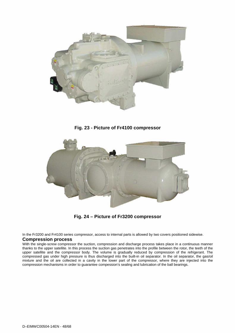
D–EIMWC00504-14EN - 48/68
Fig. 23 - Picture of Fr4100 compressor
Fig. 24 – Picture of Fr3200 compressor
In the Fr3200 and Fr4100 series compressor, access to internal parts is allowed by two covers positioned sidewise.
Compression process With the single-screw compressor the suction, compression and discharge process takes place in a continuous manner thanks to the upper satellite. In this process the suction gas penetrates into the profile between the rotor, the teeth of the upper satellite and the compressor body. The volume is gradually reduced by compression of the refrigerant. The compressed gas under high pressure is thus discharged into the built-in oil separator. In the oil separator, the gas/oil mixture and the oil are collected in a cavity in the lower part of the compressor, where they are injected into the compression mechanisms in order to guarantee compession’s sealing and lubrication of the ball bearings.
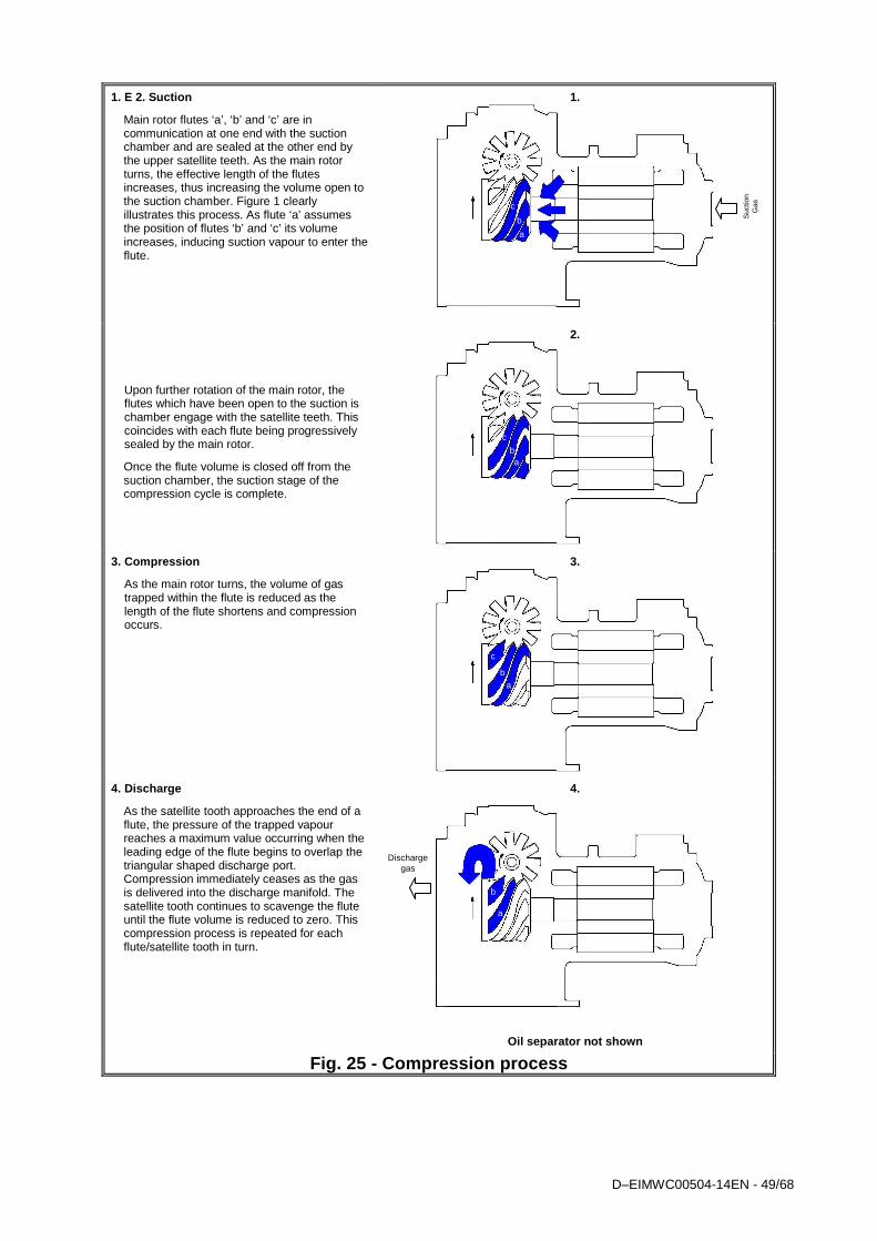
D–EIMWC00504-14EN - 49/68
1. E 2. Suction
Main rotor flutes ‘a’, ‘b’ and ‘c’ are in communication at one end with the suction chamber and are sealed at the other end by the upper satellite teeth. As the main rotor turns, the effective length of the flutes increases, thus increasing the volume open to the suction chamber. Figure 1 clearly illustrates this process. As flute ‘a’ assumes the position of flutes ‘b’ and ‘c’ its volume increases, inducing suction vapour to enter the flute.
Upon further rotation of the main rotor, the flutes which have been open to the suction is chamber engage with the satellite teeth. This coincides with each flute being progressively sealed by the main rotor.
Once the flute volume is closed off from the suction chamber, the suction stage of the compression cycle is complete.
1.
2.
3. Compression
As the main rotor turns, the volume of gas trapped within the flute is reduced as the length of the flute shortens and compression occurs.
3.
4. Discharge
As the satellite tooth approaches the end of a flute, the pressure of the trapped vapour reaches a maximum value occurring when the leading edge of the flute begins to overlap the triangular shaped discharge port. Compression immediately ceases as the gas is delivered into the discharge manifold. The satellite tooth continues to scavenge the flute until the flute volume is reduced to zero. This compression process is repeated for each flute/satellite tooth in turn.
4.
Oil separator not shown
Fig. 25 - Compression process
c
b a
c
a b
c
b a
a
b
Discharge gas
a
b
Suc
tion
G
as
b
a
c

D–EIMWC00504-14EN - 50/68
FR3200 – FR4 Compressor
Fig. 26 - Refrigeration capacity control mechanism of compressor Fr3200 – Fr4
Load Unload
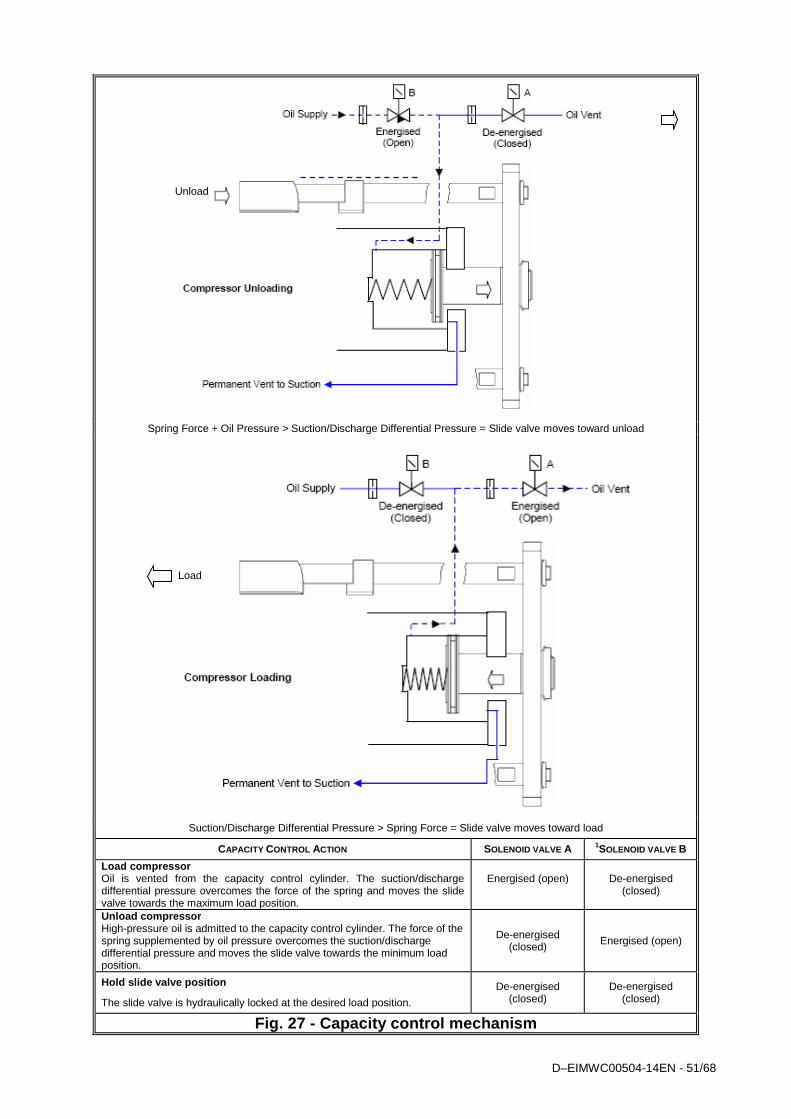
D–EIMWC00504-14EN - 51/68
Spring Force + Oil Pressure > Suction/Discharge Differential Pressure = Slide valve moves toward unload
Suction/Discharge Differential Pressure > Spring Force = Slide valve moves toward load
CAPACITY CONTROL ACTION SOLENOID VALVE A 1SOLENOID VALVE B
Load compressor Oil is vented from the capacity control cylinder. The suction/discharge differential pressure overcomes the force of the spring and moves the slide valve towards the maximum load position.
Energised (open)
De-energised (closed)
Unload compressor High-pressure oil is admitted to the capacity control cylinder. The force of the spring supplemented by oil pressure overcomes the suction/discharge differential pressure and moves the slide valve towards the minimum load position.
De-energised (closed) Energised (open)
Hold slide valve position
The slide valve is hydraulically locked at the desired load position.
De-energised (closed)
De-energised (closed)
Fig. 27 - Capacity control mechanism
Unload
Load
D–EIMWC00504-14EN - 52/68
Pre-startup checks General Once the machine has been installed, use the following procedure to check that it has been done correctly:
CAUTION Switch off the power supply of the machine before performing any checks. Failure to open the power switches at this stage can result in serious injury to the operator or even death.
Inspect all the electrical connections to the power circuits and to the compressors, including the contactors, fuse carriers and electrical terminals and check that they are clean and well secured. Even though these checks are carried out at the factory on every machine that is shipped, vibrations during transportation may loosen some electrical connections.
CAUTION Check that the electrical terminals of cables are well tightened. A loose cable can overheat and give rise to problems with the compressors.
Open discharge, liquid, liquid injection and suction (if installed) valves.
ATTENTION Do not start up the compressors if the delivery, liquid, liquid injection or suction valves are closed. Failure to open these valves can cause serious damage the compressor. It is absolutely forbidden to close the valves on the delivery and suction piping when the unit is running. These valves can be closed only when the compressor is off during maintenance of the unit. This operation must be carried out by qualified technical personnel holding the qualifications requested by local and/or European laws and with the adoption of the foreseen Personal and Collective Protection Devices.
Check the power supply voltage at the general door-block disconnector switch terminals. The power supply voltage must be the same as that on the nameplate. Maximum allowed tolerance ± 10%. Voltage unbalance between the three phases must not exceed ± 3%. The unit comes with a factory-supplied phase monitor that prevents compressors from starting if the phase sequence is incorrect. Properly connect the electrical terminals to the disconnector switch so as to ensure alarm-free operation. If the phase monitor triggers an alarm once the machine has been powered, just invert two phases at the general disconnecting switch supply (unit power supply). Never invert the electrical wiring on the monitor.
CAUTION Starting up with the wrong sequence of phases irreparably compromises operation of the compressor. Ensure that phases L1, L2 and L3 correspond in sequence to R, S, and T.
Fill the water circuit and remove air from the system’s highest point and open the air valve above the evaporator shell. Remember to close it again after filling. The design pressure on the water side of the evaporator is 10.0 bar. Never exceed this pressure at any time during the life of the machine.
IMPORTANT Before putting the machine into operation, clean the water circuit. Dirt, scaling, corrosion residue and other foreign material can accumulate inside the heat exchanger and reduce its heat exchanging capacity. Pressure drops can increase as well, thus reducing water flow. Proper water treatment therefore reduces the risk of corrosion, erosion, scaling, etc. The most appropriate water treatment must be determined locally, according to the type of system and local characteristics of the process water. The manufacturer is not responsible for damage to or malfunctioning of equipment caused by failure to treat water or by improperly treated water.
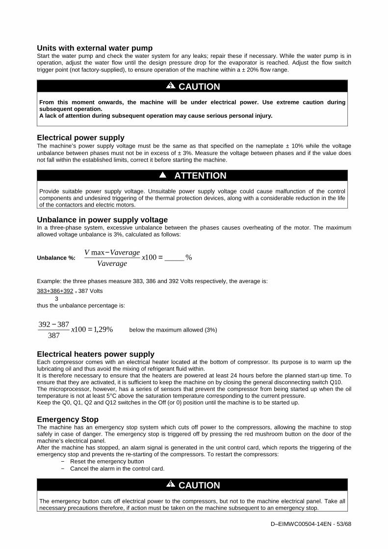
D–EIMWC00504-14EN - 53/68
Units with external water pump Start the water pump and check the water system for any leaks; repair these if necessary. While the water pump is in operation, adjust the water flow until the design pressure drop for the evaporator is reached. Adjust the flow switch trigger point (not factory-supplied), to ensure operation of the machine within a ± 20% flow range.
CAUTION From this moment onwards, the machine will be under electrical power. Use extreme caution during subsequent operation. A lack of attention during subsequent operation may cause serious personal injury.
Electrical power supply The machine’s power supply voltage must be the same as that specified on the nameplate ± 10% while the voltage unbalance between phases must not be in excess of ± 3%. Measure the voltage between phases and if the value does not fall within the established limits, correct it before starting the machine.
ATTENTION Provide suitable power supply voltage. Unsuitable power supply voltage could cause malfunction of the control components and undesired triggering of the thermal protection devices, along with a considerable reduction in the life of the contactors and electric motors.
Unbalance in power supply voltage In a three-phase system, excessive unbalance between the phases causes overheating of the motor. The maximum allowed voltage unbalance is 3%, calculated as follows:
Unbalance %: %_____100max =−
xVaverage
VaverageV
Example: the three phases measure 383, 386 and 392 Volts respectively, the average is: 383+386+392 = 387 Volts 3 thus the unbalance percentage is:
%29,1100387
387392 =−x below the maximum allowed (3%)
Electrical heaters power supply Each compressor comes with an electrical heater located at the bottom of compressor. Its purpose is to warm up the lubricating oil and thus avoid the mixing of refrigerant fluid within. It is therefore necessary to ensure that the heaters are powered at least 24 hours before the planned start-up time. To ensure that they are activated, it is sufficient to keep the machine on by closing the general disconnecting switch Q10. The microprocessor, however, has a series of sensors that prevent the compressor from being started up when the oil temperature is not at least 5°C above the saturation temperature corresponding to the current pressure. Keep the Q0, Q1, Q2 and Q12 switches in the Off (or 0) position until the machine is to be started up.
Emergency Stop The machine has an emergency stop system which cuts off power to the compressors, allowing the machine to stop safely in case of danger. The emergency stop is triggered off by pressing the red mushroom button on the door of the machine’s electrical panel. After the machine has stopped, an alarm signal is generated in the unit control card, which reports the triggering of the emergency stop and prevents the re-starting of the compressors. To restart the compressors:
− Reset the emergency button − Cancel the alarm in the control card.
CAUTION The emergency button cuts off electrical power to the compressors, but not to the machine electrical panel. Take all necessary precautions therefore, if action must be taken on the machine subsequent to an emergency stop.
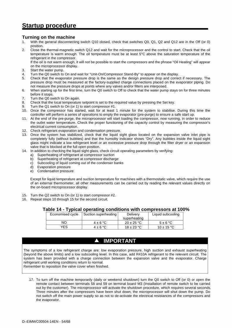
D–EIMWC00504-14EN - 54/68
Startup procedure Turning on the machine 1. With the general disconnecting switch Q10 closed, check that switches Q0, Q1, Q2 and Q12 are in the Off (or 0)
position. 2. Close the thermal-magnetic switch Q12 and wait for the microprocessor and the control to start. Check that the oil
temperature is warm enough. The oil temperature must be at least 5°C above the saturation temperature of the refrigerant in the compressor. If the oil is not warm enough, it will not be possible to start the compressors and the phrase “Oil Heating” will appear on the microprocessor display.
3. Start the water pump. 4. Turn the Q0 switch to On and wait for “Unit-On/Compressor Stand-By” to appear on the display. 5. Check that the evaporator pressure drop is the same as the design pressure drop and correct if necessary. The
pressure drop must be measured at the factory-supplied charge connections placed on the evaporator piping. Do not measure the pressure drops at points where any valves and/or filters are interposed.
6. When starting up for the first time, turn the Q0 switch to Off to check that the water pump stays on for three minutes before it stops.
7. Turn the Q0 switch to On again. 8. Check that the local temperature setpoint is set to the required value by pressing the Set key. 9. Turn the Q1 switch to On (or 1) to start compressor #1. 10. Once the compressor has started, wait for at least 1 minute for the system to stabilise. During this time the
controller will perform a series of operations to empty the evaporator (pre-purge) to ensure a safe start up. 11. At the end of the pre-purge, the microprocessor will start loading the compressor, now running, in order to reduce
the outlet water temperature. Check the proper functioning of the capacity control by measuring the compressor’s electrical current consumption.
12. Check refrigerant evaporation and condensation pressure. 13. Once the system has stabilized, check that the liquid sight glass located on the expansion valve inlet pipe is
completely fully (without bubbles) and that the humidity indicator shows “Dry”. Any bubbles inside the liquid sight glass might indicate a low refrigerant level or an excessive pressure drop through the filter dryer or an expansion valve that is blocked at the full open position.
14. In addition to checking the liquid sight glass, check circuit operating parameters by verifying: a) Superheating of refrigerant at compressor suction b) Superheating of refrigerant at compressor discharge c) Subcooling of liquid coming out of the condenser banks d) Evaporation pressure e) Condensation pressure Except for liquid temperature and suction temperature for machines with a thermostatic valve, which require the use of an external thermometer, all other measurements can be carried out by reading the relevant values directly on the on-board microprocessor display.
15. Turn the Q2 switch to On (or 1) to start compressor #2. 16. Repeat steps 10 through 15 for the second circuit.
Table 14 - Typical operating conditions with compre ssors at 100%
Economised cycle Suction superheating Delivery superheating
Liquid subcooling
NO 4 ± 6 °C 20 ± 25 °C 5 ± 6 °C YES 4 ± 6 °C 18 ± 23 °C 10 ± 15 °C
IMPORTANT The symptoms of a low refrigerant charge are: low evaporation pressure, high suction and exhaust superheating (beyond the above limits) and a low subcooling level. In this case, add R410A refrigerant to the relevant circuit. The system has been provided with a charge connection between the expansion valve and the evaporator. Charge refrigerant until working conditions return to normal. Remember to reposition the valve cover when finished.
17. To turn off the machine temporarily (daily or weekend shutdown) turn the Q0 switch to Off (or 0) or open the
remote contact between terminals 58 and 59 on terminal board M3 (Installation of remote switch to be carried out by the customer). The microprocessor will activate the shutdown procedure, which requires several seconds. Three minutes after the compressors have been shut down, the microprocessor will shut down the pump. Do not switch off the main power supply so as not to de-activate the electrical resistances of the compressors and the evaporator.
D–EIMWC00504-14EN - 55/68
IMPORTANT If the machine is not supplied with a built-in pump, do not shut down the external pump before 3 minutes have elapsed after the last compressor has shut down. Early shutdown of the pump triggers a water-flow failure alarm.
Seasonal shutdown 1. Turn switches Q1 and Q2 to the Off (or 0) position to shut down the compressors, using the normal pump-down
procedure. 2. After the compressors have been shut down, turn switch Q0 to the Off (or 0) position and wait for the built-in water
pump to shut down. If the pump is managed externally, wait for 3 minutes after the compressors have shut down before turning off the pump.
3. Open the Q12 thermal-magnetic switch (Off position) inside the control section of the electrical board and then open the general disconnecting switch Q10 to cut off the machine’s power supply entirely.
4. Close the compressor intake valves (if any) and delivery valves and also the valves located on the liquid and liquid injection line.
5. Place a warning sign on every switch that has been opened, advising to open all the valves before starting the compressors.
6. If no water and glycol mixture has been introduced into the system, discharge all the water from the evaporator and from the connected piping if the machine is to remain inactive during the winter season. One must remember that once the machine’s power supply has been cut off, the anti-freeze electrical resistance cannot function. Do not leave the evaporator and piping exposed to the atmosphere during the entire period of inactivity.
Starting up after seasonal shutdown 1. With the general disconnecting switch open, make sure that all the electrical connections, cables, terminals and
screws are well tightened to ensure good electrical contact. 2. Verify that the power supply voltage applied to the machine is within ±10% of the nominal nameplate voltage and
that the voltage unbalance between the phases is no within ±3% range. 3. Verify that all control devices are in good condition and functioning and that there is a suitable thermal load for start-
up. 4. Verify that all the connection valves are well tightened and that there are no refrigerant leaks. Always reposition the
valve covers. 5. Verify that switches Q0, Q1, Q2 and Q12 are in the open position (Off). Turn the general disconnecting switch Q10
to the On position. Doing this will allow to turn on the electrical resistances of the compressors. Wait at least 12 hours for them to warm up the oil.
6. Open all suction, delivery, liquid and liquid injection valves. Always reposition valve covers. 7. Open the water valves to fill the system and vent the air from the evaporator through the vent valve installed on its
shell. Verify that there are no water leaks from the piping.
D–EIMWC00504-14EN - 56/68
System maintenance
WARNING All routine and non-routine maintenance activities on the machine must be carried out solely by qualified personnel who are familiar with the machine characteristics, operation and maintenance procedures, and who are aware of the safety requirements and risks involved.
WARNING It 's absolutely forbidden to remove all the protections of the moving parts of the unit
WARNING The causes of repeated shutdowns deriving from triggering of safety devices must be investigated and corrected. Re-starting the unit after simply resetting the alarm can seriously damage the equipment.
WARNING A correct refrigerant and oil charge is essential for optimal operation of the machine and for environmental protection. Any oil and refrigerant recovery must conform to legislation in force.
General
IMPORTANT Besides the checks suggested in the routine maintenance program, it is recommended to schedule periodical inspections, to be carried out by qualified personnel, as follows: 4 inspections per year (every three months) for units running about 365 days per year; 2 inspections per year (1 at seasonal start-up and the second one in the middle of the season) for units running about 180 days per year with seasonal operation. 1 inspection per year 1 (at seasonal start-up) for units running about 90 days per year with seasonal operation.
IMPORTANT The manufacturer of the unit requires users to have a complete check on the unit and on the state of the pressurised refrigeration circuits carried out after ten years of use, in compliance with Italian law (Lgs. Decree 93/2000), for all groups belonging to categories I and IV, containing fluids of group 2. The manufacturer also recommends that all users analyse compressor vibrations annually and make routine inspections to check on possible refrigerant leaks. These checks ascertain that the refrigeration circuit is intact and safe and must be carried out according to local and/or European laws by personnel holding the qualifications required by such laws.
Compressor maintenance The analysis of vibrations is a good method for verifying the mechanical conditions of the compressor. Verification of vibration readings immediately after start-up and periodically on an annual basis is recommended. The compressor load must be similar to the previous measurement’s load to ensure measurement reliability.
Lubrication The units do not require a routine procedure for lubrication of components. Compressor oil is of the synthetic type and is highly hygroscopic. It is therefore advised to limit its exposure to the atmosphere during storage and filling. It is recommended that the oil be exposed to the atmosphere for no more than 10 minutes. The compressor oil filter is located under the oil separator (delivery side). Its replacement is advised when its pressure drop exceeds 2.0 bar. The pressure drop across the oil filter is the difference between the compressor discharge pressure and the oil pressure. Both these pressures can be monitored through the microprocessor for both compressors.

D–EIMWC00504-14EN - 57/68
Fig. 28 - Installation of control devices for Fr4 compresso r
Fig. 29 - Installation of control devices for Fr3200 compre ssor
SU
CT
ION
ECONOMIZER PORT
LIFTING
ECONOMIZER PORT
HIGH PRESSURE SWITCH
LIFTING
LOADING SOLENOID VALVE UNLOADING SOLENOID VALVE
DISCHARGE
TRANSDUCER FOR HIGH
PRESSURE
OIL FILTER
TRANSDUCER FOR OIL PRESSURE
OIL CHARGE COCK
OIL FILTER
TEMPERATURE SENSOR POSITION
HEATER SHEATH FOR OIL SUMP TRANSDUCER FOR OIL PRESSURE
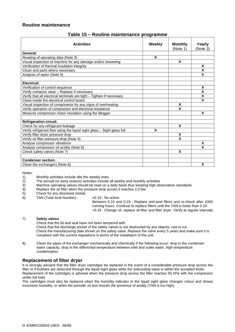
D–EIMWC00504-14EN - 58/68
Routine maintenance
Table 15 – Routine maintenance programme
Activities
Weekly
Monthly (Note 1)
Yearly
(Note 2) General: Reading of operating data (Note 3) X Visual inspection of machine for any damage and/or loosening X Verification of thermal insulation integrity X Clean and paint where necessary X Analysis of water (Note 5) X Electrical: Verification of control sequence X Verify contactor wear – Replace if necessary X Verify that all electrical terminals are tight – Tighten if necessary X Clean inside the electrical control board X Visual inspection of components for any signs of overheating X Verify operation of compressor and electrical resistance X Measure compressor motor insulation using the Megger X Refrigeration circuit: Check for any refrigerant leakage X Verify refrigerant flow using the liquid sight glass – Sight glass full X Verify filter dryer pressure drop X Verify oil filter pressure drop (Note 4) X Analyse compressor vibrations X Analyse compressor oil acidity (Note 6) X Check safety valves (Note 7) X Condens er section : Clean the exchangers (Note 8) X Notes: 1) Monthly activities include alle the weekly ones 2) The annual (or early season) activities include all weekly and monthly activities 3) Machine operating values should be read on a daily basis thus keeping high observation standards 4) Replace the oil filter when the pressure drop across it reaches 2.0 bar 5) Check for any dissolved metals 6) TAN (Total Acid Number) : ≤0.10 : No action
Between 0.10 and 0.19 : Replace anti-acid filters and re-check after 1000 running hours. Continue to replace filters until the TAN is lower than 0.10. >0.19 : Change oil, replace oil filter and filter dryer. Verify at regular intervals.
7) Safety valves Check that the lid and seal have not been tampered with. Check that the discharge socket of the safety valves is not obstructed by any objects, rust or ice. Check the manufacturing date shown on the safety valve. Replace the valve every 5 years and make sure it is
compliant with the current regulations in terms of the installation of the unit. 8) Clean the pipes of the exchanger mechanically and chemically if the following occur: drop in the condenser
water capacity, drop in the differential temperature between inlet and outlet water, high temperature condensation.
Replacement of filter dryer It is strongly advised that the filter dryer cartridges be replaced in the event of a considerable pressure drop across the filter or if bubbles are observed through the liquid sight glass while the subcooling value is within the accepted limits. Replacement of the cartridges is advised when the pressure drop across the filter reaches 50 kPa with the compressor under full load. The cartridges must also be replaced when the humidity indicator in the liquid sight glass changes colour and shows excessive humidity, or when the periodic oil test reveals the presence of acidity (TAN is too high).

D–EIMWC00504-14EN - 59/68
Procedure to replace the filter dryer cartridge
CAUTION Ensure proper water flow through the evaporator during the entire servicing period. Interrupting the water flow during this procedure would cause the evaporator to freeze, with consequent breakage of internal piping.
1. Shut down the relevant compressor by turning the Q1 or Q2 switch to Off. 2. Wait until the compressor has stopped and close the valve located on the liquid line. 3. Once the compressor has stopped, place a label on the compressor start-up switch, to prevent undesired
start-ups. 4. Close the compressor suction valve (if any). 5. Using a recovery unit, remove surplus refrigerant from the liquid filter until atmospheric pressure is reached.
The refrigerant must be stored in a suitable and clean container.
CAUTION To protect the environment, do not release removed refrigerant into the atmosphere. Always use a recovery and storage device.
6. Balance internal pressure with external pressure by pressing the vacuum pump valve installed on the filter cover.
7. Remove the filter dryer cover. 8. Remove the filter elements. 9. Install the new filter elements in the filter.
CAUTION Do not start the machine before the cartridge has b een correctly inserted in the filter dryer. The uni t manufacturer will accept no responsibility for any damage to persons or property caused during unit functioning if the filter dryer cartridges have not been correctly inserted.
10. Replace the cover gasket. Do not allow any mineral oil onto the filter gasket so as not to contaminate the
circuit. Use only compatible oil for this purpose (POE). 11. Close the filter cover. 12. Connect the vacuum pump to the filter and pull vacuum to 230 Pa. 13. Close the vacuum pump valve. 14. Recharge the filter with the refrigerant recovered during emptying. 15. Open the liquid line valve. 16. Open the suction valve (if any). 17. Start the compressor by turning switch Q1 or Q2.
Replacement of filter dryer It is strongly advised that the filter dryer cartridges be replaced in the event of a considerable pressure drop across the filter or if bubbles are observed through the liquid sight glass while the subcooling value is within the accepted limits. Replacement of the cartridges is advised when the pressure drop across the filter reaches 50 kPa with the compressor under full load. The cartridges must also be replaced when the humidity indicator in the liquid sight glass changes colour and shows excessive humidity, or when the periodic oil test reveals the presence of acidity (TAN is too high).
Procedure to replace the filter dryer cartridge
ATTENTION Ensure proper water flow through the evaporator during the entire servicing period. Interrupting the water flow during this procedure would cause the evaporator to freeze, with consequent breakage of internal piping.
18. Shut down the relevant compressor by turning the Q1 or Q2 switch to Off. 19. Wait until the compressor has stopped and close the valve located on the liquid line.
D–EIMWC00504-14EN - 60/68
20. Once the compressor has stopped, place a label on the compressor start-up switch, to prevent undesired start-ups.
21. Close the compressor suction valve (if any). 22. Using a recovery unit, remove surplus refrigerant from the liquid filter until atmospheric pressure is reached.
The refrigerant must be stored in a suitable and clean container.
ATTENTION To protect the environment, do not release removed refrigerant into the atmosphere. Always use a recovery and storage device.
23. Balance internal pressure with external pressure by pressing the vacuum pump valve installed on the filter cover.
24. Remove the filter dryer cover. 25. Remove the filter elements. 26. Install the new filter elements in the filter.
ATTENTION Do not start the machine before the cartridge has b een correctly inserted in the filter dryer. The uni t manufacturer will accept no responsibility for any damage to persons or property caused during unit functioning if the filter dryer cartridges have not been correctly inserted.
27. Replace the cover gasket. Do not allow any mineral oil onto the filter gasket so as not to contaminate the
circuit. Use only compatible oil for this purpose (POE). 28. Close the filter cover. 29. Connect the vacuum pump to the filter and pull vacuum to 230 Pa. 30. Close the vacuum pump valve. 31. Recharge the filter with the refrigerant recovered during emptying. 32. Open the liquid line valve. 33. Open the suction valve (if any). 34. Start the compressor by turning switch Q1 or Q2.
Rplacement of the oil filter
ATTENTION The lubrication system has been designed to keep most of the oil charge inside the compressor. During operation, however, a small amount of oil circulates freely in the system, conveyed by the refrigerant. The amount of replacement oil going into the compressor should therefore be equal to the quantity removed rather than the amount stated on the nameplate; this will avoid excess of oil during the following start-up. The quantity of oil removed from the compressor must be measured after having allowed the refrigerant present in the oil to evaporate for a suitable amount of time. To reduce the refrigerant content in the oil to a minimum, it is advised that the electrical resistances be kept on and that the oil be removed only when it has reached a temperature of 35÷45°C.
ATTENTION The replacement of the oil filter requires careful attention with regard to oil recovering; the oil must not be exposed to air for more than about 30 minutes. In case of doubts, verify oil acidity or, if it is not possible to carry out the measurement, replace the charge of lubricant with fresh oil stored in sealed tanks or in a way that meet supplier specifications.
Fr3200 compressor The compressor oil filter is located under the oil separator (discharge side). It is strongly advised that it be replaced when its pressure drop exceeds 2.0 bar. The pressure drop across the oil filter is the difference between the compressor delivery pressure minus oil pressure. Both pressures can be controlled through the microprocessor for both compressors.
Required materials: Oil filter Code 95816-401 – Quantity 1 Gaskets kit Code 128810988 – Quantity 1
D–EIMWC00504-14EN - 61/68
Compatible oils:
Mobile Eal Arctic 68 ICI Emkarate RL 68H
The standard oil charge for a compressor is 16 litres. Procedure to replace oil filter 1) Shut down both compressors by turning the Q1 and Q2 switches to the Off position. 2) Turn the Q0 switch to Off, wait for the circulation pump to turn off and open the general disconnecting switch
Q10 to cut off the machine’s electrical power supply. 3) Place a label on the handle of the general disconnecting switch in order to prevent accidental start-up. 4) Close the suction, discharge and liquid injection valves. 5) Connect the recovery unit to the compressor and recover the refrigerant in a suitable and clean container. 6) Evacuate the refrigerant until the internal pressure has turned negative (compared to atmospheric pressure).
The amount of refrigerant dissolved in the oil is reduced to a minimum in this way. 7) Drain the oil in the compressor by opening the drain valve located under the oil separator. 8) Remove the oil filter cover and remove the internal filter element. 9) Replace the cover and internal sleeve gaskets. Do not lubricate the gaskets with mineral oil in order not to
contaminate the system. 10) Insert the new filter element. 11) Reposition the filter cover and tighten the screws. The screws must be tightened alternately and progressively
setting the torque wrench at 60 Nm. 12) Charge the oil from the upper valve located on the oil separator. Considering the high hygroscopy of ester oil, it
should be charged as quickly as possible. Do not expose ester oil to the atmosphere for more than 10 minutes. 13) Close the oil charging valve. 14) Connect the vacuum pump and evacuate the compressor up to a vacuum of 230 Pa. 15) On reaching the above vacuum level, close the vacuum pump valve. 16) Open the system’s delivery, suction and liquid injection valves. 17) Disconnect the vacuum pump from the compressor. 18) Remove the warning label from to the general disconnecting switch. 19) Close the general disconnecting switch Q10 to supply power to the machine. 20) Start the machine by following the start-up procedure described above. FR4 compressor
ATTENTION The lubrication system has been designed to keep most of the oil charge inside the compressor. During operation, however, a small amount of oil circulates freely in the system, conveyed by the refrigerant. The amount of replacement oil going into the compressor should therefore be equal to the quantity removed rather than the amount stated on the nameplate; this will avoid excess of oil during the following start-up. The quantity of oil removed from the compressor must be measured after having allowed the refrigerant present in the oil to evaporate for a suitable amount of time. To reduce the refrigerant content in the oil to a minimum, it is advised that the electrical resistances be kept on and that the oil be removed only when it has reached a temperature of 35÷45°C.
ATTENTION The replacement of the oil filter requires careful attention with regard to oil recovering; the oil must not be exposed to air for more than about 30 minutes. In case of doubts, verify oil acidity or, if it is not possible to carry out the measurement, replace the charge of lubricant with fresh oil stored in sealed tanks or in a way that meet supplier specifications.
Fr4200 compressor The compressor oil filter is located at the coupling of the oil inlet piping and the compressor body (suction side). It is strongly advised that it be replaced when its pressure drop exceeds 2.0 bar. The pressure drop across the oil filter is the difference between the compressor delivery pressure minus oil pressure. Both pressures can be controlled through the microprocessor for both compressors.
Required materials:
Oil filter Code 95816-401 – Quantity 1 Gaskets kit Code 128810988 – Quantity 1
Compatible oils:
Mobil Eal Arctic 68

D–EIMWC00504-14EN - 62/68
ICI Emkarate RL 68H The standard oil charge for a compressor is 16 litres.
Oil filter replacement procedure
Procedure to replace oil filter 1) Shut down both compressors by turning the Q1 and Q2 switches to the Off position. 2) Turn the Q0 switch to Off, wait for the circulation pump to turn off and open the general disconnecting switch
Q10 to cut off the machine’s electrical power supply. 3) Place a label on the handle of the general disconnecting switch in order to prevent accidental start-up. 4) Close the suction, discharge and liquid injection valves. 5) Connect the recovery unit to the compressor and recover the refrigerant in a suitable and clean container. 6) Evacuate the refrigerant until the internal pressure has turned negative (compared to atmospheric pressure).
The amount of refrigerant dissolved in the oil is reduced to a minimum in this way. 7) Drain the oil in the compressor by opening the drain valve located under the oil separator. 8) Remove the oil filter cover and remove the internal filter element. 9) Replace the cover and internal sleeve gaskets. Do not lubricate the gaskets with mineral oil in order not to
contaminate the system. 10) Insert the new filter element. 11) Reposition the filter cover and tighten the screws. The screws must be tightened alternately and progressively
setting the torque wrench at 60 Nm. 12) Charge the oil from the upper valve located on the oil separator. Considering the high hygroscopy of ester oil, it
should be charged as quickly as possible. Do not expose ester oil to the atmosphere for more than 10 minutes. 13) Close the oil charging valve. 14) Connect the vacuum pump and evacuate the compressor up to a vacuum of 230 Pa. 15) On reaching the above vacuum level, close the vacuum pump valve. 16) Open the system’s delivery, suction and liquid injection valves. 17) Disconnect the vacuum pump from the compressor. 18) Remove the warning label from to the general disconnecting switch. 19) Close the general disconnecting switch Q10 to supply power to the machine. 20) Start the machine by following the start-up procedure described above. Refrigerant charge
ATTENTION The units have been designed to operate with R410A refrigerant. So DO NOT USE refrigerants other than R410A.
ATTENTION When refrigerant gas is added to or removed from the system, ensure proper water flow through the evaporator for the entire charge/discharge time. Interrupting the water flow during this procedure would cause the evaporator to freeze with consequent breakage of its internal piping. Damage caused by freezing makes the warranty void.
WARNING Removal of the refrigerant and replenishing operations must be performed by technicians who are qualified to use the appropriate materials for this unit. Unsuitable maintenance can result in uncontrolled losses in pressure and fluid. Do not disperse the refrigerant and lubricating oil in the environment. Always be equipped with a suitable recovery system.
The units ship with a full refrigerant charge, but in some cases it might be necessary to replenish the machine in the field.
WARNING
Always verify the causes of a loss of refrigerant. Repair the system if necessary then recharge it.
The machine can be replenished under any stable load condition (preferably between 70 and 100%) and under any ambient temperature condition (preferably above 20°C). The machine should be kept running for at least 5 minutes to allow the condensation pressure to stabilise.
D–EIMWC00504-14EN - 63/68
The subcooling value is about 3-4°C. Once the subcooling section has been completely filled, additional refrigerant will not increase system efficiency. However, a small additional quantity of refrigerant (1÷2 kg) makes the system slightly less sensitive. N.B.: Subcooling varies and requires a few minutes to re-stabilise. However, subcooling should not come below 2°C under any condition. Also, the subcooling value can change slightly as the water temperature and the suction superheating vary. As the suction superheating value decreases, there is a corresponding decrease in subcooling. One of the two following scenarios can arise in a machine without refrigerant:
1. If the refrigerant level is slightly low, flow of bubbles can be seen through the liquid sight glass. Replenish the circuit as described in the replenishment procedure.
2. If the gas level in the machine is moderately low, the corresponding circuit could have some low-pressure stops. Replenish the corresponding circuit as described in the replenishment procedure.
Procedure to replenish refrigerant 1) If the machine has lost refrigerant, it is necessary to first establish the causes before carrying out any
replenishment operation. The leak must be found and repaired. Oil stains are a good indicator, as they can appear in the vicinity of a leak. However, this is not necessarily always a good search criterion. Searching with soap and water can be a good method for medium to large leaks, while an electronic leak detector is required to find small leaks.
2) Add refrigerant to the system through the service valve on the suction pipe or through the Schrader valve located on the evaporator inlet pipe.
3) The refrigerant can be added under any load condition between 25 and 100% of the system capacity. Suction superheating must be beteen 4 and 6°C.
4) Add enough refrigerant to fill the liquid sight glass entirely, so that no flow of bubbles can be seen anymore. Add an extra 2 ÷ 3 kg of refrigerant as a reserve, to fill the subcooler if the compressor is operating at 50 – 100% load.
5) Check the subcooling value by reading the liquid pressure and the liquid temperature near the expansion valve. The subcooling value must be between 3 and 5°C. The subcooling value will be lower at 75 ÷ 100% load and higher at 50% load.
6) Overcharging the system will cause a rise in the compressor’s discharge pressure.
D–EIMWC00504-14EN - 64/68
Standard Checks Temperature and pressure sensors The unit comes factory-equipped with all the sensors listed below. Periodically check that their measurements are correct by means of reference instruments (manometers, thermometers); correct the wrong readings as necessary using the microprocessor keypad. Well-calibrated sensors ensure better efficiency for the machine and a longer lifetime. Note: Refer to the microprocessor use and maintenance manual for a complete description of applications, settings and adjustments. All sensors are preassembled and connected to the microprocessor. The descriptions of each sensor are listed below: Outlet water temperature sensor – This sensor is located on the evaporator outlet water connection and is used by the microprocessor to control the machine load depending on the system’s thermal load. It also helps control the evaporator’s antifreeze protection. Inlet water temperature sensor – This sensor is located on the evaporator inlet water connection and is used for monitoring the return water temperature. Compressor discharge pressure transducer – This is installed on every compressor and allows to monitor the discharge pressure and to control the fans. Should the condensation pressure increase, the microprocessor will control the compressor load in order to allow it to function even if the compressor flow gas must be reduced. It also contributes to the oil control logic. Oil pressure transducer – This is installed on every compressor and allows to monitor the oil pressure. The microprocessor uses this sensor to inform the operator on the conditions of the oil filter and on how the lubrication system is functioning. By working together with the high- and low-pressure transducers, it protects the compressor from problems deriving from poor lubrication. Low-pressure transducer – This is installed on every compressor and allows to monitor the compressor suction pressure along with low pressure alarms. It contributes to complementing the oil control logic. Suction sensor – This is installed optionally (if the electronic expansion valve has been requested) on every compressor, and allows to monitor the suction temperature. The microprocessor uses the signal from this sensor to control the electronic expansion valve. Compressor discharge temperature sensor – This is installed on every compressor and allows to monitor compressor discharge pressure and oil temperature. The microprocessor uses the signal from this sensor to control the liquid injection and to shut down the compressor in case that the discharge temperature reaches 110°C. It also protects the compressor from pumping liquid refrigerant at start-up.
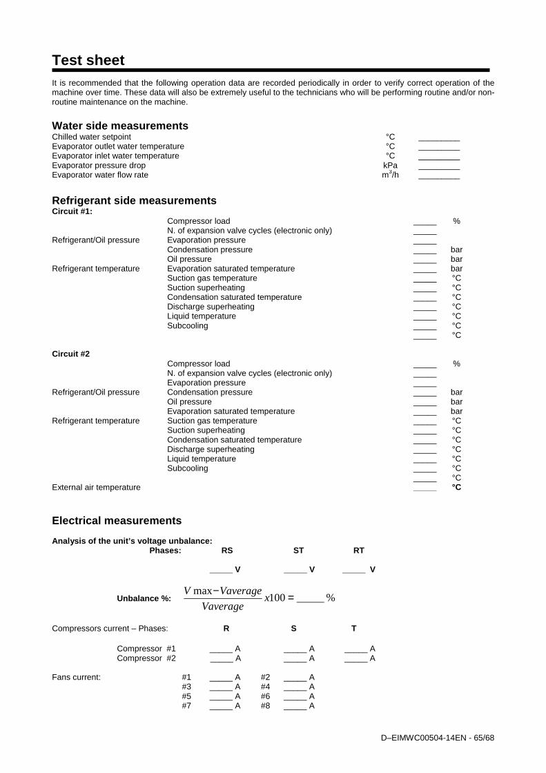
D–EIMWC00504-14EN - 65/68
Test sheet It is recommended that the following operation data are recorded periodically in order to verify correct operation of the machine over time. These data will also be extremely useful to the technicians who will be performing routine and/or non-routine maintenance on the machine.
Water side measurements Chilled water setpoint °C _________ Evaporator outlet water temperature °C _________ Evaporator inlet water temperature °C _________ Evaporator pressure drop kPa _________ Evaporator water flow rate m3/h _________
Refrigerant side measurements Circuit #1: Compressor load _____ % N. of expansion valve cycles (electronic only) _____ Refrigerant/Oil pressure Evaporation pressure _____ Condensation pressure _____ bar Oil pressure _____ bar Refrigerant temperature Evaporation saturated temperature _____ bar Suction gas temperature _____ °C Suction superheating _____ °C Condensation saturated temperature _____ °C Discharge superheating _____ °C Liquid temperature _____ °C Subcooling _____ °C _____ °C Circuit #2 Compressor load _____ % N. of expansion valve cycles (electronic only) _____ Evaporation pressure _____ Refrigerant/Oil pressure Condensation pressure _____ bar Oil pressure _____ bar Evaporation saturated temperature _____ bar Refrigerant temperature Suction gas temperature _____ °C Suction superheating _____ °C Condensation saturated temperature _____ °C Discharge superheating _____ °C Liquid temperature _____ °C Subcooling _____ °C _____ °C External air temperature _____ °C Electrical measurements Analysis of the unit’s voltage unbalance: Phases: RS ST RT _____ V _____ V _____ V
Unbalance %: %_____100max =−
xVaverage
VaverageV
Compressors current – Phases: R S T
Compressor #1 _____ A _____ A _____ A Compressor #2 _____ A _____ A _____ A
Fans current: #1 _____ A #2 _____ A #3 _____ A #4 _____ A #5 _____ A #6 _____ A #7 _____ A #8 _____ A
D–EIMWC00504-14EN - 66/68
Service and limited warranty All machines are factory-tested and guaranteed for 12 months as of the first start-up or 18 months as of delivery. These machines have been developed and constructed according to high quality standards ensuring years of failure-free operation. It is important, however, to ensure proper and periodical maintenance in accordance with all the procedures listed in this manual. We strongly advise stipulating a maintenance contract with a service authorized by the manufacturer in order to ensure efficient and problem-free service, thanks to the expertise and experience of our personnel. It must also be taken into consideration that the unit requires maintenance also during the warranty period. It must be borne in mind that operating the machine in an inappropriate manner, beyond its operating limits or not performing proper maintenance according to this manual can void the warranty. Observe the following points in particular, in order to conform to warranty limits: 1. The machine cannot function beyond the specified limits 2. The electrical power supply must be within the voltage limits and without voltage harmonics or sudden changes. 3. The three-phase power supply must not have un unbalance between phases exceeding 3%. The machine must
stay turned off until the electrical problem has been solved. 4. No safety device, either mechanical, electrical or electronic must be disabled or overridden. 5. The water used for filling the water circuit must be clean and suitably treated. A mechanical filter must be installed at
the point closest to the evaporator inlet. 6. Unless there is a specific agreement at the time of ordering, the evaporator water flow rate must never be above
120% and below 80% of the nominal flow rate.
D–EIMWC00504-14EN - 67/68
Obligatory routine checks and starting up apparatus es under pressure The units are included in category IV of the classification according to European Directive PED 97/23/EC. For chillers belonging to this category, some local regulations require a periodic inspection by an authorized agency. Please check with your local requirements.
Important information regarding the refrigerant use d This product contains fluorinated greenhouse gases covered by the Kyoto Protocol. Do not vent gases into the atmosphere. Refrigerant type: R410A GWP(1) value: 1975 (1)GWP = global warming potential The refrigerant quantity is indicated on the unit name plate. Periodical inspections for refrigerant leaks may be required depending on European or local legislation. Please contact your local dealer for more information.
Disposal
The unit is made of metal and plastic parts. All these parts must be disposed of in accordance with the local regulations in terms of disposal. Lead batteries must be collected and taken to specific refuse collection centres.

D–EIMWC00504-14EN - 68/68
The present publication is drawn up by of information only and does not constitute an offer binding upon Daikin Applied Europe S.p.A.. Daikin Applied Europe S.p.A. has compiled the content of this publication to the best of its knowledge. No express or implied warranty is given for the completeness, accuracy, reliability or fitness for particular purpose of its content, and the products and services presented therein. Specification are subject to change without prior notice. Refer to the data communicated at the time of the order. Daikin Applied
Europe S.p.A. explicitly rejects any liability for any direct or indirect damage, in the broadest sense, arising from or related to the use and/or interpretation of this publication. All content is copyrighted by Daikin Applied Europe S.p.A..
DAIKIN APPLIED EUROPE S.p.A. Via Piani di Santa Maria, 72 - 00040 Ariccia (Roma) - Italia Tel: (+39) 06 93 73 11 - Fax: (+39) 06 93 74 014 http://www.daikinapplied.eu