water and wastewater standards and specifications
TRANSCRIPT

CITY OF NEWARK
WATER AND WASTEWATER
STANDARDS AND SPECIFICATIONS
Effective Date: August 6, 2018
Last Revised: February 2019

City of Newark www.newarkde.gov Public Works and Water Resources Department
2 Last Revised February 2019
Table of ContentsIntroduction ....................................................................................................................................3
Design and Installation Standards for Water .................................................................................3
Water System Design and Main Sizing.........................................................................................3
Water Mains & Fittings ...............................................................................................................5
Fire Hydrants ...............................................................................................................................5
Individual Residential Water Services .........................................................................................6
Private Water Systems ................................................................................................................7
Design and Installation Standards for Sanitary Sewer...................................................................7
Sanitary Sewer Mains...................................................................................................................7
Sanitary Force Mains....................................................................................................................9
Sanitary Sewer Manholes...........................................................................................................10
Sanitary Sewer Laterals ..............................................................................................................11
Pump Stations ............................................................................................................................12
Private Sanitary Sewer Systems .................................................................................................12
Inspection and Testing for Water and Sanitary Sewer ................................................................13
Backfill of Water and Sewer Main..............................................................................................13
Testing Water Mains ..................................................................................................................13
Disinfection of Water Mains ......................................................................................................13
Testing Sanitary Sewer Mains ....................................................................................................14
Testing Force Mains ...................................................................................................................15
Fire Suppression System Shutoff................................................................................................15
Construction Water Rent (Paid by Builder) ................................................................................15
Appendix A – Standard Utility Details ..........................................................................................16
Appendix B – Sanitary Sewer Pump Station Specifications .........................................................70

City of Newark www.newarkde.gov Public Works and Water Resources Department
3 Last Revised February 2019
I. INTRODUCTION:
The City of Newark Public Works and Water Resources (PWWR) Department has been committed to providing high-quality water since 1888. The City provides all customers within the City limits with drinking water and wastewater services. The City also provides drinking water to customers in certain territories outside the City.
The Water Division of the Public Works and Water Resources Department is responsible for the maintenance and operation of all the equipment and facilities at each of the nine water supply wells, the Curtis Water Treatment Plant, the South Well Field Water Treatment Plant, nine finished water storage tanks, one raw water storage tank, a 317 million gallon raw water reservoir, and six booster pumping stations. More than 1.0 billion gallons of water are pumped through 143 miles of pipe annually to serve more than 10,000 water service connections. As a result of our regular sampling and testing program, we are proud to report Newark meets or exceeds the water quality standards of the Delaware Division of Public Health Office of Drinking Water and the Environmental Protection Agency.
The Sewer Division of the Public Works and Water Resources Department is responsible for the City's 94 miles of sanitary sewer collection and three sewer pumping stations with force mains. The sanitary sewer system operates primarily on a gravity system, while the lowest points of the City are served by a series of three lift stations. The sewage flows out of the City’s system and through the New Castle County system before being treated at the Wilmington Regional Wastewater Treatment Facility.
Due to the magnitude and varying components of the City’s water and waste water infrastructure, the Department has prepared this document to assist customers, developers, contractors and consultants in understanding the policies, procedures and standards associated with water, wastewater, and stormwater infrastructure. In turn, this will help make it easier for you to do business with the City of Newark, Public Works and Water Resources Department with respect to water and waste water. If you have any questions, please don’t hesitate to contact us by phone at 302-366-7000.
II. DESIGN AND INSTALLATION STANDARDS FOR WATER
A. WATER SYSTEM DESIGN AND MAIN SIZING:
1. All water mains are to be designed and constructed to meet the minimum standards as set by the State of Delaware Office of Drinking Water.
2. All water mains, including those not designed to provide fire protection, shall be sized after a hydraulic analysis based on flow demands and pressure requirements. The system shall have adequate capacity to meet anticipated peak demands while maintaining not less than twenty-five (25) pounds per square inch (psi) and not more than one hundred (100) psi at ground level at all points in the water distribution system including fire flows.
3. Minimum main line diameter of 8” within the public right of way where providing fire protection. Water velocity within the main at the design fire flow rate shall not exceed 10 ft/sec nor shall head loss exceed 5’ per 100’ of main for the maximum daily flow plus fire flow condition.
4. Individual building services are not subject to the minimum main diameter requirement and shall instead be designed for the design flow rate for the building. At no time shall the velocity within the building service exceed 10 ft/sec.
5. Where the manufacturer’s recommended pipe joint deflection is exceeded, mechanical joint bends shall be required and installed to the satisfaction of the PWWR inspector.
6. Gate valves shall be provided at an interval not to exceed 500’ in commercial districts and one block or 800’ (whichever is less) in residential districts. The PWWR Department can increase

City of Newark www.newarkde.gov Public Works and Water Resources Department
4 Last Revised February 2019
the minimum distance requirement where unit density is low and future development is not expected. Variances shall be approved be the Director of Public Works and Water Resources.
7. A minimum of two valves shall be provided at all tees and three valves at any crosses, as determined by the PWWR Department.
8. A gate valve shall be provided at the right of way line on all building services. Valves associated with the tapping sleeve are not sufficient to meet this requirement.
9. Dead ends shall be minimized to the maximum extent practicable in order to provide increased reliability of service and reduce head loss.
10. A blow off shall be installed on all dead-end water mains; blow off shall be sized to provide flows which will result in a velocity of at least 2.5 feet per second in the water main being flushed. A fire hydrant may be substituted for a blow off at the discretion of the PWWR Director. No flushing device shall be directly connected to any storm drain, storm sewer, or sanitary sewer.
11. Fire hydrants should be provided at each street intersection and at intermediate points between intersections as required to meet State and local fire code requirements. The maximum spacing of fire hydrants shall be such that no portion of any lot is more than 500 feet from a hydrant. The PWWR Director may designate additional hydrants if necessary.
12. Air relief valves shall be provided at high points in the system where air can accumulate. Air relief valves shall be sized appropriately for the diameter of the main served. Air relief valves shall be located within a manhole meeting the City of Newark minimum sanitary sewer manhole requirements and shall have a solid, watertight lid labeled “Water”. Air relief valves shall not be used in situations where flooding of the manhole may occur. Discharge piping from air relief valves shall not connect directly to any storm drain, storm sewer, or sanitary sewer.
13. A minimum ten (10) feet horizontal and eighteen (18) inch vertical separation, as measured from the outside of each pipe, shall be provided for all water mains from sanitary sewer (gravity lines and force mains). This shall be the case whether the water main is above or below the sewer. Wherever possible the sewer shall be beneath the water main. Crossings shall be arranged so that the sewer joints will be equidistant and as far as possible from the water main joints.
14. A minimum eighteen (18) inch vertical separation, as measured from the outside of each pipe, shall be provided for all water mains from storm sewer. Due to the limited width of some streets, the horizontal separation between all water mains and storm sewer shall be provided to the maximum extent practicable. When feasible, a minimum ten (10) feet horizontal separation, as measured from the outside of each pipe, shall be provided for all water mains from storm sewers in accordance with Ten States Standards.
15. Water mains shall have a minimum of eighteen (18) inch clearance from electric lines, gas mains, and all other utilities.
16. No water line (mains, services, etc.) shall pass through or come in contact with any part of a sanitary sewer or storm sewer manhole.
17. Publicly maintained water mains located outside of the right of way shall be centered within a minimum twenty (20) foot wide public maintenance and access easement, dedicated to the City. No plantings or structures are permitted to be constructed within this easement.
18. Privately maintained water mains shall be centered within a minimum twenty (20) foot wide, private maintenance and access easement. No plantings or structures are permitted to be constructed within this easement.
19. Off-road water main shall include a “turf trail”, as detailed in City of Newark Standard Details.20. Contractors shall schedule and perform work in a manner that minimizes disruption of water
service to City of Newark customers. This includes notifying the Public Works and Water Resources Department a minimum 48 hours (2 weekdays) in advance of any planned service disruptions. Any disruption resulting in a loss of pressure will require the inspector to be there to collect a bacteria sample.

City of Newark www.newarkde.gov Public Works and Water Resources Department
5 Last Revised February 2019
21. At no point shall anyone other than authorized City personnel operate any water valves unless permission in writing is granted by the City.
B. WATER MAINS & FITTINGS:
1. All water mains shall be Ductile Iron push on, cement lined Class 52 ductile iron pipe, with locking gaskets, unless otherwise specified by Public Works and Water Resources Department (PWWR).
2. Minimum cover of forty-two (42) inches shall be provided over all water mains as measured from finished grade to the top of the pipe.
3. Backfill material shall be select borrow from the bottom of the trench to one foot above the top of pipe. Native excavated material may be used if approved by the Department.
4. Water mains shall be pressure rated, buttressed at bends and marked with 12-gauge tracer wire. Place metallic detection tape on first lift of material over pipe.
5. All water mains shall be wrapped in V-Bio Enhanced Polyethylene Encasement manufactured by McWane Ductile or approved equal as determined by the PWWR Department. Information on the V-Bio product can be found here: http://mcwaneductile.com/upl/downloads/library/mcwane-ductile-v-bio.pdf
6. Tapping sleeves shall be Mueller H-615, Mueller Stainless H-304 or approved equal as determined by the PWWR Department.
7. Tapping valves shall be Mueller T-2360-19, open left.8. Main gate valves shall be Mueller A-2362, open left.9. All insertion valves shall be Advanced Valve Technologies EZ Valve. 90-degree actuators will be
required where burial depths will not accommodate a standard valve configuration. Insertion valves may be located in a manhole where existing burial depths are less than 42”. A minimum of 6” must be maintained between the bottom of the manhole lid and the valves operating nut.
10. Valve boxes shall be Mueller H-10360 or approved equal as determined by the PWWR Department. Valve boxes shall be screw type adjustable to final grade.
11. The valve boxes shall be installed with lids reading “WATER” for the domestic system.12. All bends shall be buttressed with 3500 psi concrete and wrapped with plastic.13. All brass fittings shall conform to the Federal “Reduction of Lead in Drinking Water Act” signed
into law in 2011 and effective January 1, 2014.14. Water mains shall be pressure tested with services installed and curb stops in place.15. Allowable leakage shall be per AWWA Standards and DIPRA recommendations.16. Fire hydrants shall be included in all tests.
C. FIRE HYDRANTS:
1. The minimum size for all fire hydrant leads shall be six (6) inches.2. Hydrant laterals shall be restraining tee, six (6) inch resilient gate valve and box with six (6) inch
Ductile Iron Pipe.3. Fire hydrants shall be furnished with a factory applied safety yellow coating.4. Hydrants shall be Super Centurion 250/HS Mueller, A-423, buttressed and rodded.5. Size Valve Opening – 5 ¼ inch, open left.6. Fire hydrants shall be set to stand plumb with the nozzles parallel with or at right angles to the
curb. The steamer nozzle shall face the curb. Ground safety flange should be kept close to the surrounding final grade.
7. A three (3') ft clear space shall be maintained around the circumference of all fire hydrants except as otherwise required or approved. A clear space of not less than 7’-6” shall be provided in front of each hydrant connection.
8. Nozzle Arrangement:

City of Newark www.newarkde.gov Public Works and Water Resources Department
6 Last Revised February 2019
Two– 2 ½ inch Hose Connections, National Standard Thread One– 5 ¼ inch Pumper Connections, National Standard Thread Lateral Connection – 6-inch Mechanical Joint Operating Nuts – All 1 ½ inch Pentagon
D. INDIVIDUAL RESIDENTIAL WATER SERVICES:
1. Corporation stops shall be ¾ inch Mueller H-15008N or B-25008N, tapped on upper 1/3 (45 degree).
2. Saddle taps shall be Mueller BR2B Bronze.3. Curb stops shall be Mueller H-15209N or P-25209N.4. Curb boxes shall be Mueller H-10350, or equal.5. House services shall be ¾ inch soft copper tubing type “K”.6. Minimum depth of cover is 42 inches.7. Meter yokes shall be Mueller H-1412N.8. Water meters shall be located in pits located 2’ behind the right of way line unless directed
otherwise by the Public Works and Water Resources Department. 9. Meter pits for meters 1” and under shall be Mueller Thermal-Coil, 42” depth, with integral dual
check valve. Lid type will depend on pit location and must be approved by the Public Works and Water Resources Department. All water meter pits must be installed on a 6” thick stone bed and per manufacturer’s recommendations.
Meter Pit Sizing:
5/8” Meter = (Catalog # 200-CS-15-42-F-S-A-S-N)5/8”x3/4” Meter = (Catalog # 203-CS-15-42-F-S-A-S-N)3/4” Meter = (Catalog # 250-CS-15-42-F-S-A-S-N)1” Meter = (Catalog # 330-CS-15-42-F-S-A-S-N)1 ½” Meter = (Catalog # 500-VB-24-42-F-B-A)2” Meter = (Catalog # 550-VB-27-42-F-B-A)
10. Compound meters larger than 2” shall be installed in accordance with drawings approved by Public Works and Water Resources Department. See Appendix A for typical meter pit details.
11. Individual water meters will be provided for each dwelling and/or commercial unit. The developer will be responsible for the cost of the meters and the meter pits. The City will determine the size of the meters in coordination with the developer. Meter pits shall be Mueller Thermal-Coil meter pits.
12. In apartment buildings, water meter shall be located as close as possible to where the domestic main enters the building in a meter bank setup. The meter room shall be readily accessible to the City of Newark. A ¼ turn locking ball valve shall be located immediately before and after the meter.
13. Water meters and transmitters for all services shall be purchased from the Public Works and Water Resources Department.
14. The developer will be responsible for all repeaters necessary to reliably read the water meters in their installed location from our existing AMI mesh.
15. Adequate backflow protection shall be installed on domestic and fire services to prevent undesired reverse flow of contaminants into the potable water system.
E. PRIVATE WATER SYSTEMS:

City of Newark www.newarkde.gov Public Works and Water Resources Department
7 Last Revised February 2019
1. Water systems that are proposed for private ownership and maintenance shall conform to these design requirements as if the proposed system were to be owned and maintained by the City of Newark.
III. DESIGN AND INSTALLATION STANDARDS FOR SANITARY SEWER
A. SANITARY SEWER MAINS:
1. Proposed average daily sewer flows shall be in accordance with the latest revision of the New Castle County Department of Public Works Sewer Capacity Manual.
2. The minimum size for collector system pipe shall be eight (8) inches in nominal diameter.3. Proposing pipe sizes greater than eight (8) inches in nominal diameter must be justified by flow
velocity analysis, or as directed by the Department. Analysis must indicate that a minimum velocity of two (2) feet per second will be achieved from the proposed average daily flow, as calculated by Manning’s Equation, using 0.013 as the coefficient of roughness. Calculations shall be signed and sealed by a Professional Engineer, licensed by and in good standing with the State of Delaware.
4. Proposed pipe slopes shall be no less than the following:
Nominal Sewer SizeMinimum Slope in FeetPer 100 Feet (m/100 m)
8 inch (200 mm) 0.5010 inch (250 mm) 0.2812 inch (300 mm) 0.2214 inch (350 mm) 0.1715 inch (375 mm) 0.1516 inch (400 mm) 0.1418 inch (450 mm) 0.1221 inch (525 mm) 0.1024 inch (600 mm) 0.0827 inch (675 mm) 0.06730 inch (750 mm) 0.05833 inch (825 mm) 0.05236 inch (900 mm) 0.04639 inch (975 mm) 0.04142 inch (1050 mm) 0.037
5. Pipe slopes on terminal runs of the proposed sanitary sewer system shall be no less than 1% (0.0100 ft/ft).
6. Pipe diameters shall increase in size in the direction of flow as dictated by flow velocity analysis. When joining pipe sections, the crown of the upstream pipe section shall never be lower in elevation than the crown of the downstream pipe section.
7. Proposed sewer lines shall have more than four (4) feet of cover over the crown of the pipe, but no more than twenty (20) feet of cover below final surrounding grade.
8. Sanitary sewer mains shall be SDR-26 PVC. Mains where the depth is less than five (5) feet or greater than twenty (20) feet at any point along its length shall be Class 52 D.I.P.

City of Newark www.newarkde.gov Public Works and Water Resources Department
8 Last Revised February 2019
9. The Department may require alternative pipe materials to accommodate conditions when proposed sewer lines are greater than fifteen (15) feet in depth
10. All utilities and water courses within twenty (20) feet of the proposed sewer system must be clearly depicted on the sanitary sewer plan and profile views. This includes overhead utilities and poles.
11. Sewer mains and materials shall be installed on a six (6) inch bed of Delaware #57 stone to grade and backfilled with stone to approximately six (6) inches over pipe.
12. A casing pipe is generally required by the Delaware Department of Transportation (DELDOT) when crossing a public road right of way. Crossing shall be oriented as close to perpendicular with the right of way as possible. The casing pipe shall be of steel and, of adequate thickness and, a minimum of three pipe sizes larger than the carrier pipe. The carrier pipe shall be installed through the casing using casing spacers as approved by the Department.
13. Separation, reinforcing, pipe specifications and other provisions for utility and water course crossings shall be provided in accordance with the Recommended Standards for Wastewater Utilities, 2004 Edition, Section 36 entitled “Sewers in Relation to Streams” and/or Section 38 entitled “Protection of Water Supplies.”
14. Provisions for the utility or water course crossing shall extend a minimum of ten (10) feet beyond the point of crossing, but in no way shall be less than twenty (20) feet in total length. Provisions may include but are not limited to use of pressure rated pipe, casing pipe and/or concrete encasement.
15. Final requirements of the crossing shall be determined by the Department during design review.16. The preferred horizontal separation between the proposed sanitary sewer infrastructure and
any existing or proposed utility infrastructure shall be no less than ten (10) feet. A horizontal separation of greater than ten (10) feet may be required by the Department due to factors that include depth and/or size of the sanitary sewer infrastructure or utility, access or other site restrictions, or other considerations as determined by the Department.
17. Six (6) inch minimum thickness, 3500 psi concrete encasement shall be required whenever a sewer main passes within 18 inches of another utility, over or under, measured from outside of pipe wall.
18. Proposed public sanitary sewer infrastructure located outside of a public right of way shall be located within the limits of a sanitary sewer easement.
19. Easements shall be clearly depicted on plans, including proposed dimensions, and benefactor of the easement (City of Newark, New Castle County or private entity).
20. Sanitary sewer easements shall be at least twenty (20) feet in width and shall run continuous with the proposed sewer infrastructure until it enters into the public right of way or existing, legally established easement.
21. Easements for sanitary sewer lines that abut a building shall be no less than forty (40) feet in width if the sanitary sewer line is greater than ten (10) feet deep measured from ground surface.
22. The sanitary sewer pipe shall be centered in the proposed sanitary sewer easement.23. Proposed sanitary sewer lines shall not be located in generic utility easements, stormwater
easements or landscape buffers.24. No permanent structure shall be located within the sanitary sewer easement. Permanent
structures include but are not limited to stormwater management infrastructure and other utilities, and landscaping features such as trees, shrubs, fences and signs.
a. The Department may allow existing structures to be located within the limits of the sanitary sewer easement, as long as it can be determined that no acceptable alternate route is available, the structure was constructed and/or installed prior to the construction of the proposed sanitary sewer line, and the structure will not restrict access for continued operation and maintenance of the proposed sanitary sewer line. In the case of a fence, the Department may require gates be installed such that access to the proposed sanitary sewer line is provided.

City of Newark www.newarkde.gov Public Works and Water Resources Department
9 Last Revised February 2019
25. Off-road sanitary sewer lines shall include a “turf trail”, as detailed in City of Newark Standard Details.
26. Any possibility of significant impact to existing landscaping shall be clearly noted on the plans.27. More detailed information concerning topography or other area attributes may be requested by
the Department to provide a more complete picture of existing and proposed conditions when off-road sewer is proposed. A full topographic shall be performed and furnished to the City for any off-road sewer easements.
28. The Department may require a specific material, pipe class and/or interior or exterior coating or encasement where, in the Department’s opinion, conditions warrant. Conditions may include but are not limited to industrial use, projects where excessive velocity is anticipated, and/or poor substrate conditions.
a. Alternative pipe materials may include but are not limited to high density polyethylene (HDPE), reinforced concrete pipe (RCP), and/or ductile iron pipe (DIP).
b. Alternative pipe coatings and/or linings may include but are not limited to epoxy lining, cured in place pipe lining (CIPPL), concrete lining, PVC (for RCP) lining, and/or bituminous coating.
29. Contractors shall schedule and perform work in a manner that minimizes disruption of water service to City of Newark customers. This includes notifying the Public Works and Water Resources Department a minimum 48 hours (2 weekdays) in advance of any planned service disruptions.
B. SANITARY FORCE MAINS:
1. Minimum cover of forty-two inches (42”) shall be provided over all force mains as measured from finished grade to the top of the pipe.
2. Force mains shall have a minimum of eighteen-inch (18”) clearance from drains, electric lines, gas mains, and all other utilities.
3. All force mains shall be appropriately sized based upon the design requirements for the pump station or grinder pump. All force mains four-inches (4”) and larger shall be ductile iron pipe unless otherwise approved by the Department.
4. Nonmetallic force main shall be AWWA C-900, minimum SDR18, or HDPE DR11 (directional drilling applications) when warranted by the application and approved by PWWR.
5. Force mains shall be pressure rated, buttressed at bends and marked with 12-gauge tracer wire. Place metallic sewer tape on first lift of material over pipe.
6. A permanent Rhino TriView marker or approved equal shall be installed at horizontal bends and crossing and spaced no greater than 300 linear foot interval for all force main located outside of a roadway.
7. The minimum velocity shall not be less than two feet per second (2 fps) for force main design. In general force main velocities shall not exceed five and one-half feet per second (5-1/2 fps) for force main design.
8. If the total dynamic head at the pump discharge exceeds 100 feet, a larger diameter force main will be used, provided that a velocity of two feet per second (2 fps) can be maintained.
9. Air release valves shall be provided on lines at all local high points along the force main profile and shall be located in an open bottom manhole.
10. DIP force main shall be Class 52, Protecto 401 ceramic epoxy lined with outside surface bituminous coated.
11. All Fittings shall be 350psi rated, ANSI/AWWA – C153/A21.53, ductile or gray iron. Protecto 401 ceramic epoxy lined.
12. Pipe to Pipe Joint restraints shall be Megalugs, TR FLEX, or approved equal and be able to be deflected as required per approved plans.
13. Contractors shall schedule and perform work in a manner that minimizes disruption of water service to City of Newark customers. This includes notifying the Public Works and Water

City of Newark www.newarkde.gov Public Works and Water Resources Department
10 Last Revised February 2019
Resources Department a minimum 48 hours (2 weekdays) in advance of any planned service disruptions.
14. At no point shall anyone other than authorized City personnel operate any water valves unless permission in writing is granted by the City.
15. All force main discharge manholes and immediate downstream manhole shall be lined with a reinforced epoxy resin lining system as approved by the Department.
C. SANITARY SEWER MANHOLES:
1. Manholes shall conform to all City of Newark Standard Specifications for Construction.2. Manholes shall be located to facilitate on-going maintenance and operation of the sewer
system. The Department may require additional manholes as determined to be beneficial to on-going maintenance and operation.
3. Manholes shall not be located in gutters, swales, or low spots in roads.4. Manholes shall be placed at all locations where the sanitary sewer changes lateral direction, pipe
size, pipe slope, and no more than three-hundred (300) linear feet apart.5. Manholes shall include a minimum bench width of eighteen (18) inches on either side of the
channel.6. Sanitary sewer manhole frame and cover elevations shall be verified to match the final road
elevation prior to final paving. Concrete adjustment rings shall be used to match the final paving elevation. No more than twelve (12) inches of adjustment will be permitted.
7. Drop manholes shall not be used without authorization. If approved, drop manholes shall be designed per the City of Newark Standard Details. Outside drops are not acceptable.
8. Lamp holes are not acceptable.9. The top of manholes located in unpaved areas shall be at an elevation six (6) inches above
surrounding final grade or one (1) foot above the one-hundred (100) year flood plain elevation, if applicable. The top of manholes located in unpaved areas shall not be greater than four (4) feet above final grade. A berm shall surround elevated manhole rims, as shown in the City of Newark Standard Details.
10. The Department may require a specific material and/or interior or exterior coating where it, in the Department’s opinion, conditions warrant. Conditions may include but are not limited to industrial use, where hydrogen sulfide gases and/or high velocities are anticipated, and/or poor subsurface conditions.
11. Alternative manhole materials and coatings may include but are not limited to HDPE, CCFRPM, polymer concrete, epoxy coatings/linings, PVC and/or bituminous coatings.
12. All manholes shall be precast and all channels inside manholes shall be poured concrete, 4,000 # mix. Channel repairs shall be a concrete mixture of one part hydraulic cement (water plug) to two parts non-shrink grout.
13. All manholes shall have poured concrete collar around outside between the manhole frame and the precast manhole. All off--road frame and collars are to be bolted down to the manhole with sealant at each interface with bolt down lids.
14. All manhole frames and covers shall be watertight, as per City of Newark Water and Waste Water specifications. An approved bituminous seal coating shall be applied to the exterior of all manholes.
15. When a contractor ties into an existing manhole, they shall be responsible to bring that manhole up to present codes and specifications.
16. A six (6) inch bed of Stone (Delaware #57) shall be laid under the manhole base prior to installation, including stone around and over the inlet and discharge pipes. Wet or unstable ground conditions will require undercutting and additional stone depth.
D. SANITARY SEWER LATERALS:

City of Newark www.newarkde.gov Public Works and Water Resources Department
11 Last Revised February 2019
1. Each proposed lot shall be serviced by an individual sanitary sewer lateral connection to the public sanitary sewer system. If the proposed use of the building includes food preparation such that a grease interceptor is required, two (2) separate service laterals are required such that flows from kitchens or containing grease or oils flow to the grease trap and not directly to the public sewer.
2. Requirements of the sanitary sewer lateral located outside the public right-of-way or public sanitary sewer easement shall be in accordance with the latest edition of the International Plumbing Code.
3. The minimum sanitary lateral size is four (4) inches in internal diameter and shall serve no more than one dwelling unit.
4. The sanitary sewer lateral located within the public right-of-way or public sanitary sewer easement shall not be less than six (6) inches in internal diameter.
5. The minimum slope for the section of the sanitary sewer lateral located within the public right-of-way or public sanitary sewer easement shall be 2% (0.0200 ft/ft).
6. No sanitary sewer laterals shall be allowed to connect directly to sanitary sewer pipe having an internal diameter greater than fifteen (15) inches without approval of the Department.
7. The minimum vertical distance between the invert of the sanitary sewer lateral connection at the sanitary sewer main and the lowest sewered floor of the house or building shall be five (5) feet. The minimum vertical distance required is waived if the determining floor is at least twelve (12) inches higher in elevation than the manhole rim elevation immediately upstream from the lateral connection.
8. All sanitary sewer laterals shall be minimum O-ring SDR-26. Laterals where the depth is less than five (5) feet or greater than twenty (20) feet at any point along its length shall be Class 52 D.I.P. sewer pipe.
9. Maximum depth is twenty (20) feet and minimum depth is four (4) feet. Laterals where the depth is less than four (4) feet or greater than twenty (20) feet at any point along its length shall be class 50 D.I.P. sewer pipe.
10. Sanitary sewer cleanouts shall be installed at every bend and spaced at 150 linear foot intervals measured from the upstream entrance of the clean-out.
11. Any sanitary sewer laterals proposed to be reused shall be visually inspected (televised) by the developer and approved for reuse by the Department. The City’s Water and Wastewater Inspector shall be present when the lateral is being televised. A recording of the video inspection shall be provided to the Department. Inspection shall be performed at a speed appropriate to allow for proper assessment of the pipe and connections.
12. If Orangeburg pipe is discovered during the design or construction phase of any sanitary sewer improvement, it shall be completely removed and replaced with an approved pipe material.
13. Cleanout screw caps flush to one (1) inch below finished grade in grass area and placed one (1) foot behind the right of way.
14. All combination cleanouts shall be of the John Manville or Harco type (consisting of 45-degree wye and 45-degree bend). Tee-Wyes will not be accepted. Cleanouts located within a traffic bearing location shall be installed with a heavy duty cast iron frame and cover to prevent damage to the cleanout and lateral. Applicable material is provided by East Jordan Iron Works, part number #1566.
15. Back water valve/check to be installed as per International Plumbing Code #715. This valve shall be valve Clean/Check inc #EBV-401B or equal.
16. All proposed land development plans that include a Commercial Food Establishment (CFE) shall include an external grease interceptor in accordance with design the requirements herein.a. Location should be accessible for maintenance. If located within a vehicular traffic area,
grease interceptor shall be H-20 loaded.

City of Newark www.newarkde.gov Public Works and Water Resources Department
12 Last Revised February 2019
b. Sizing calculations performed in accordance with Environmental Protection Agency (EPA) 2 Model, “Recommended Grease Trap Sizing Formula,” or latest revision. Minimum storage capacity of grease interceptors shall be 1,000 gallons.
c. Only sanitary sewer laden with fats, oils and grease from food preparation appliances and fixtures shall be directed into a grease interceptor.
d. Grease interceptors must be constructed of either pre-cast concrete or fiberglass with an internal baffle.
E. PUMP STATIONS:
1. All proposed pump stations shall be sized to handle a minimum average daily flow of 45,000 gallons per day, or the equivalent flow of one hundred fifty (150) single family dwelling units.
2. If a proposed subdivision does not meet the minimum flow requirement, the land developer shall follow the exception process described herein. The developer shall provide at a minimum build-out flow projections and mapping for the region that may be serviced by the proposed pump station, including but not limited to topographic features, a count of existing lots currently serviced by on-site septic systems, and development potential of undeveloped property. If the study is accepted by the Department, feasibility of the results of the engineering study shall be demonstrated at each land development phase. The developer further recognizes that final approval of the sanitary sewer construction plans is dependent on incorporating results from the build- out analysis into the proposed sanitary sewer system.
3. Pump stations shall be designed in accordance with the latest version of the Pump Station Design Guidelines, provided in Appendix B, by a Professional Engineer, licensed by and in good standing with the State of Delaware.
4. Grinder pump stations shall be reserved primarily for single-family dwellings. Exceptions may be made with the approval of the Public Works and Water Resources Director or their designee.
5. Minimum effective storage for a residential or commercial grinder pump shall be 50% of the average daily volume generated in a two (2) day period.
6. Grinder pump stations if approved by the Department shall be E-One Extreme WH471 or approved equal.
F. PRIVATE SANITARY SEWER SYSTEMS:
1. Sanitary sewer systems and pump stations that are proposed for private ownership and maintenance shall conform to these design requirements as if the proposed system were to be owned and maintained by the City of Newark.
IV. INSPECTION AND TESTING FOR WATER AND SANITARY SEWER
A. BACKFILL OF WATER AND SEWER MAIN:
1. Backfill Inside City of Newark Roads:a. Select borrow from the bottom of the trench to one foot above the top of pipe. Native
excavated material may be used if approved by the Department.b. The balance of the trench for both water and sewer shall be backfilled with crusher run (CR-
6) compacted in eight (8) inch layers. The trench shall be cut back one (1) foot on each side and capped with eight (8) inches of Class A concrete to two (2) inches below existing surface. A two (2) inch mat of “TYPE C” hot mix shall be placed on the concrete flush with existing roadway. An approved tack coating shall be applied prior to installation of “Type C” hot mix.
2. Backfill Inside State Maintained Roads:

City of Newark www.newarkde.gov Public Works and Water Resources Department
13 Last Revised February 2019
a. Backfill for pipe trenches shall be in accordance with Delaware State Highway standards and specifications and generally requires eight (8) inches of Class A concrete base above the crusher run (R-6) backfill, with a two (2) inch over-lay of hot-mix to finished grade. Trench restoration within the DelDOT right of way shall be coordinated with DelDOT.
B. TESTING WATER MAINS:
1. Water mains shall be tested with services installed and curb stops in place.2. Test shall be for two (2) hours of 150 psi hydrostatic pressure.3. Allowable leakage is AWWA Standards and DIPRA recommendations.4. Fire hydrants shall be included in all tests.5. Any inspection or test showing defects or testing failure shall be replaced at the expense of the
Contractor, and inspection and tests shall be repeated. All repairs shall be made with new material; failure to meet the tests specified above will be sufficient cause to reject the work until the defects are satisfactorily repaired. All expenses and costs incurred in carrying out the specified tests shall be borne by the Contractor. The Public Works and Water Resources Department shall have sole authority and responsibility to determine if the tests are acceptable
C. DISINFECTION OF WATER MAINS
1. Disinfection by chlorination of all new water main shall be completed and a satisfactory bacteriological report obtained prior to placing the pipe in service. “Open-bore” flushing shall be completed before chlorination is begun.
2. Chlorine shall be applied using hypochlorite commercial products such as HTH or approved equal. The chlorinating agent shall be applied at the beginning of the section adjacent to the feeder connection, insuring treatment of the entire water pipe. Water shall be fed slowly into the new water pipe with chlorine applied in amounts to produce a dosage of 50 ppm. Application of the chlorine solution shall continue until the required residual of not less than 50 ppm free chlorine is evident at all extremities of the newly constructed line.
3. The following table is to be used as a guide for chlorinating pipes by the calcium hypochlorite and water mixture method. The given dosage per 100 feet results in a chlorine solution of 40 to 50 ppm. This dosage takes into account that Contractors most frequently use granular HTH, which is 65% pure. If another chlorinating agent is used, the dosage must be adjusted.
PIPE DIAMETER DOSAGE PER 100 FEET4” 0.60 oz6” 1.36 oz8” 2.75 oz
10” 4.30 oz12” 6.19 oz16” 11.00 oz20” 17.00 oz
4. A residual of not less than 50 ppm free chlorine shall be produced in all parts of the water pipe. After 24 hours detention there shall be a minimum free chlorine residual of 25 ppm in all parts of the water pipe.
5. The water shall be flushed from the water pipe at its extremities, including all curb stops, until the replacement water chlorine residuals are equal to those of the permanent source of supply. The de-chlorinated water and water used for flushing shall be disposed of in a manner approved by the Department, and in accordance with current requirements of the State of Delaware

City of Newark www.newarkde.gov Public Works and Water Resources Department
14 Last Revised February 2019
Department of Natural Resources and Environmental Control.6. After the water pipe system has been thoroughly flushed, bacteria samples will be taken at
representative locations in the system by the Department. If the samples are positive, the pipe disinfection procedure shall be repeated, and additional samples taken for bacteriological examination. All bacteriological sampling and analysis fees are listed in the Department’s Schedule of Fees.
D. TESTING SANITARY SEWER MAINS:1. Sanitary mains shall be tested with all laterals tied in and complete cleanouts in place.2. Test shall be 5 pounds for 15 minutes with no allowable leakage.3. Any inspection or test showing defects or testing failure shall be replaced at the expense of the
Contractor, and inspection and tests shall be repeated. All repairs shall be made with new material; failure to meet the tests specified above will be sufficient cause to reject the work until the defects are satisfactorily repaired. All expenses and costs incurred in carrying out the specified tests shall be borne by the Contractor. The Public Works and Water Resources Department shall have sole authority and responsibility to determine if the tests are acceptable.
4. Each manhole, pump station wet well, meter pit, or similar structure installed within the sanitary sewer system shall be inspected for infiltration by a Public Works and Water Resources representative before being put into service. Any inspections showing defects or signs of infiltration, shall be repaired or replaced at the expense of the Contractor, and inspection shall be repeated. All repairs shall be made with new material; failure to prohibit infiltration into wastewater utility system will be sufficient cause to reject the work until the defects are satisfactorily repaired or replaced.
5. All sanitary sewer lines and manholes shall be televised. All lines must be flushed and cleaned by the Contractor prior to televising. The PWWR Inspector shall be on site for all CCTV inspections. Electronic copies of the recording shall be provided to the PWWR Department
6. If the video inspection shows any defects, such defective work or material shall be replaced at the expense of the Contractor, and the video inspection and any other required tests shall be repeated. All repairs shall be made with new material; failure to meet testing requirements will be sufficient cause to reject the work until the defects are satisfactorily repaired. All expenses and costs incurred in carrying out the specified tests and video inspections shall be borne by the Contractor.
E. TESTING FORCE MAINS:
1. Force mains shall be tested with laterals installed and shutoff valves in place.2. All bends in forced main system shall be buttressed and treated as a water line. 3. Test shall be for two (2) hours of 100 psi hydrostatic pressure.4. Allowable leakage is AWWA Standards and DIPRA recommendations.
F. FIRE SUPPRESSION SYSTEM SHUTOFF:
1. All fire suppression systems shall have a shut-off valve installed on the supply line located on the exterior of the building with large valve box with fire on lid.
2. Should the fire system be supplied from the existing domestic water lateral, or vice versa, the valves for each system shall be positioned so that either valve can be opened or closed without terminating the water supply to the opposite service.
3. The valve boxes shall be installed with lids reading “FIRE” for the fire suppression system.
G. CONSTRUCTION WATER RENT (PAID BY BUILDER):

City of Newark www.newarkde.gov Public Works and Water Resources Department
15 Last Revised February 2019
1. Builders shall pay water rent for usage prior to the certificate of occupancy being granted. Upon application for a building permit, the applicant shall pay a fee for the use of water during construction at the current rate as reflected on the building permit.

City of Newark www.newarkde.gov Public Works and Water Resources Department
16 Last Revised February 2019
APPENDIX A

u:\p
wop
erat
ions
\CAD
\new
ark
pww
r sta
ndar
d de
tails
\Tab
le o
f Con
tent
s.dw
g
PLO
TTED
: Fe
brua
ry 1
, 201
9
220 SOUTH MAIN STREETNEWARK, DELAWARE 19711
(302) 366-7000www.newarkde.gov@CityofNewarkDE
CITY OF NEWARKPUBLIC WORKS AND WATERRESOURCES DEPARTMENT
TABLE OF CONTENTS
THIS DRAWING AND THE DESIGN SHOWN ARETHE EXCLUSIVE PROPERTY OF THE CITY OFNEWARK AND SHALL NOT BE ALTERED OR
COPIED WITHOUT EXCLUSIVE PERMISSION.ANY REUSE WITHOUT WRITTEN VERIFICATION
OR ADAPTATION BY THE CITY OF NEWARKFOR THE SPECIFIC PURPOSE INTENDED WILL
BE AT OWNERS SOLE RISK AND WITHOUTLIABILITY OR LEGAL EXPOSURE TO THE CITY
OF NEWARK.
ALL CONSTRUCTION SHALL BE COMPLETED INACCORDANCE WITH THE LATEST CITY OF
NEWARK STANDARDS AND SPECIFICATIONSAND IN COMPLIANCE WITH THE
OCCUPATIONAL SAFETY AND HEALTH ACT OF1970 AND THE RULES AND REGULATIONS
THERETO.
NONE
MWF
EJR
FEBRUARY 2019DATE:
SCALE:
DRAWN BY:
APPROVED BY:
SHEET:
_
TABLE OF CONTENTSSheet TitleGeneral UtilityU1 Standard Buttress for Pipe FittingsU2 Standard Air Release ManholeU3 Pressure Reducing Valve ManholeU4 Force Main inside Drop Manhole DetailU5 Force Main Discharge to ManholeU6 Doghouse Manhole DetailU7 Abandoned Manhole DetailU8 Utility Trench Road Crossing DetailU9 Longitudinal Trench Detail for City RoadwayU10 Reinforced Concrete Pipe Trench DetailU11 Transition from HDPE to DIPU12 Utility Turf Trail DetailWaterW1 Water Trench DetailW2 Standard Fire Hydrant InstallationW3 Existing Fire Hydrant Tie BackW4 Standard Water Service DetailW5 Standard Installation Curb Box and Valve BoxW6 Standard Blow Off DetailW7 Standard Manhole Frame & CoverW8 Typical Water Main RelocationW9 Water Service ConnectionW10 Connection to Existing Water MainW11 Valve RestraintW12 Omni C2W13 Omni T2W14 iPERLW15 Inside Water Meter DetailW16 Standard Water Meter Pit (5-8in to 1in)W17 Standard Water Meter Pit (1 1-2in to 2in)W18 Flow Meter Pit with BypassW19 Large Meter Pit DetailW20 Water Meter PitW21 Standard Insertion Valve DetailW22 Shallow Main Insertion Valve DetailSanitary SewerSS1 Sanitary Sewer Trench DetailSS2 Typical Cleanout (Paved)SS3 Typical Cleanout (Sidewalk)SS4 Typical Cleanout (Grass)SS5 Double Cleanout DetailSS6 Standard Manhole Frame and CoverSS7 Locking Manhole AssemblySS8 Manhole Adjustment and Concrete CollarSS9 48in Manhole DetailSS10 60in Manhole DetailSS11 72in (and Larger) Manhole DetailSS12 Standard Sanitary Sewer Indside Drop ManholeSS13 Standard Connections for Manhole Flow ChannelsSS14 Standard Manhole StepsSS15 Sanitary Sewer Shallow ManholeSS16 Concrete Cradle and EncasementSS17 Sanitary Sewer Force Main CleanoutSS18 Grease Interceptor Detail

BUTTRESSES FOR PLUGS AND CAPS
BUTTRESSES FOR TEES
BUTTRESSES FOR HORIZONTAL BENDS
BUTTRESSES FOR VERTICAL BENDS
NOTES:
1. ALL FITTINGS MUST BE WRAPPED WITH PLASTIC BEFORECONCRETE BUTTRESS IS POURED.
2. ALL BOLTS TO BE FREE FROM CONCRETE AND ACCESSIBLE FORFUTURE REPAIRS.
ELEVATIONPLAN
PLAN
SECTION
PLANSECTION A-A
SECTION ELEVATION
HORIZONTAL BENDSSIZE
BEND 6" 8" 12"
45°D 1'-5" 1'-10" 3'-10"
E 6" 8" 12"
22 12°D 11" 1'-2" 1'-10"
E 4" 6" 9"
11 14°D 11" 12" 1'-2"
E 4" 6" 7"
BENDSIZE 45° 22 12° 11 14°
6"A 6" 6" 6"
B 1'-5" 11" 6"
C 6" 8"4" 6"
8"A 6" 6" 6"
B 1'-10" 1'-2" 6"
C 8" 6" 6"
12"A 6" 6" 6"
B 2'-10" 1'-10" 1'-2"
C 11" 8" 7"
VERTICAL BENDS
TEESSIZE
6" 8" 12"J 6" 8" 1'-1"
K 10" 1'-1" 1'-7"
L 8" 8" 1'-10"
PLUG OR CAPSIZE
6" 8" 12"M 1'-1" 1'-5" 2'-1"
N 1'-7" 2'-2" 3'-2"
O 7" 9" 1'-1"
M
OO
N
L
K
K
J
J
D
A
E E
4" MIN.
6"
C C
4" MIN.
A
B
A
u:\p
wop
erat
ions
\CAD
\new
ark
pww
r sta
ndar
d de
tails
\U1
Stan
dard
But
tres
s for
Pip
e Fi
ttin
gs.d
wg
PL
OTT
ED:
Janu
ary
30, 2
019
220 SOUTH MAIN STREETNEWARK, DELAWARE 19711
(302) 366-7000www.newarkde.gov@CityofNewarkDE
CITY OF NEWARKPUBLIC WORKS AND WATERRESOURCES DEPARTMENT STANDARD BUTTRESS FOR PIPE
FITTINGS
THIS DRAWING AND THE DESIGN SHOWN ARETHE EXCLUSIVE PROPERTY OF THE CITY OFNEWARK AND SHALL NOT BE ALTERED OR
COPIED WITHOUT EXCLUSIVE PERMISSION.ANY REUSE WITHOUT WRITTEN VERIFICATION
OR ADAPTATION BY THE CITY OF NEWARKFOR THE SPECIFIC PURPOSE INTENDED WILL
BE AT OWNERS SOLE RISK AND WITHOUTLIABILITY OR LEGAL EXPOSURE TO THE CITY
OF NEWARK.
ALL CONSTRUCTION SHALL BE COMPLETED INACCORDANCE WITH THE LATEST CITY OF
NEWARK STANDARDS AND SPECIFICATIONSAND IN COMPLIANCE WITH THE
OCCUPATIONAL SAFETY AND HEALTH ACT OF1970 AND THE RULES AND REGULATIONS
THERETO.
NOT TO SCALE
MWF
EJR
AUGUST 2018DATE:
SCALE:
DRAWN BY:
APPROVED BY:
SHEET:
U1

SAND CUSHION BETWEENPIPE & BRICK ARCH
AIR VALVE TO BE SIMPLEXA.V. OR APPROVED EQUAL
TAP AS DIRECTED BYENGINEER AND IN
ACCORDANCE WITHMANUFACTURER'S
RECOMMENDATIONS
3500 PSI CONCRETE3'-4" 1'-4"
8"1'-6
"VA
RIAB
LE4'-0"
PRECAST MANHOLESEE DETAIL SS7
NOTES:1. MANHOLE COVER TO BE STAMPED APPROPRIATE TO INDICATE TYPE OF UTILITY AS FOLLOWS:
1a. WATER SHALL BE LABELED "NEWARK WATER".1b. SANITARY SEWER SHALL BE LABELED "NEWARK SANITARY SEWER".1c. ANY MANHOLE FOR PRIVATE WATER OR SEWER SHALL NOT INCLUDE THE WORD "NEWARK" ANYWHERE ON THE LID BUT SHOULD STILL
INDICATE THE APPROPRIATE UTILITY TYPE.
5"5"
GRAVEL
TYPICAL CROSS SECTION
CONCRETECOLLAR
u:\p
wop
erat
ions
\CAD
\new
ark
pww
r sta
ndar
d de
tails
\U2
Stan
dard
Air
Rele
ase
Man
hole
.dw
g
PLO
TTED
: Ja
nuar
y 30
, 201
9
220 SOUTH MAIN STREETNEWARK, DELAWARE 19711
(302) 366-7000www.newarkde.gov@CityofNewarkDE
CITY OF NEWARKPUBLIC WORKS AND WATERRESOURCES DEPARTMENT STANDARD AIR RELEASE
MANHOLE
THIS DRAWING AND THE DESIGN SHOWN ARETHE EXCLUSIVE PROPERTY OF THE CITY OFNEWARK AND SHALL NOT BE ALTERED OR
COPIED WITHOUT EXCLUSIVE PERMISSION.ANY REUSE WITHOUT WRITTEN VERIFICATION
OR ADAPTATION BY THE CITY OF NEWARKFOR THE SPECIFIC PURPOSE INTENDED WILL
BE AT OWNERS SOLE RISK AND WITHOUTLIABILITY OR LEGAL EXPOSURE TO THE CITY
OF NEWARK.
ALL CONSTRUCTION SHALL BE COMPLETED INACCORDANCE WITH THE LATEST CITY OF
NEWARK STANDARDS AND SPECIFICATIONSAND IN COMPLIANCE WITH THE
OCCUPATIONAL SAFETY AND HEALTH ACT OF1970 AND THE RULES AND REGULATIONS
THERETO.
NOT TO SCALE
MWF
EJR
AUGUST 2018DATE:
SCALE:
DRAWN BY:
APPROVED BY:
SHEET:
U2
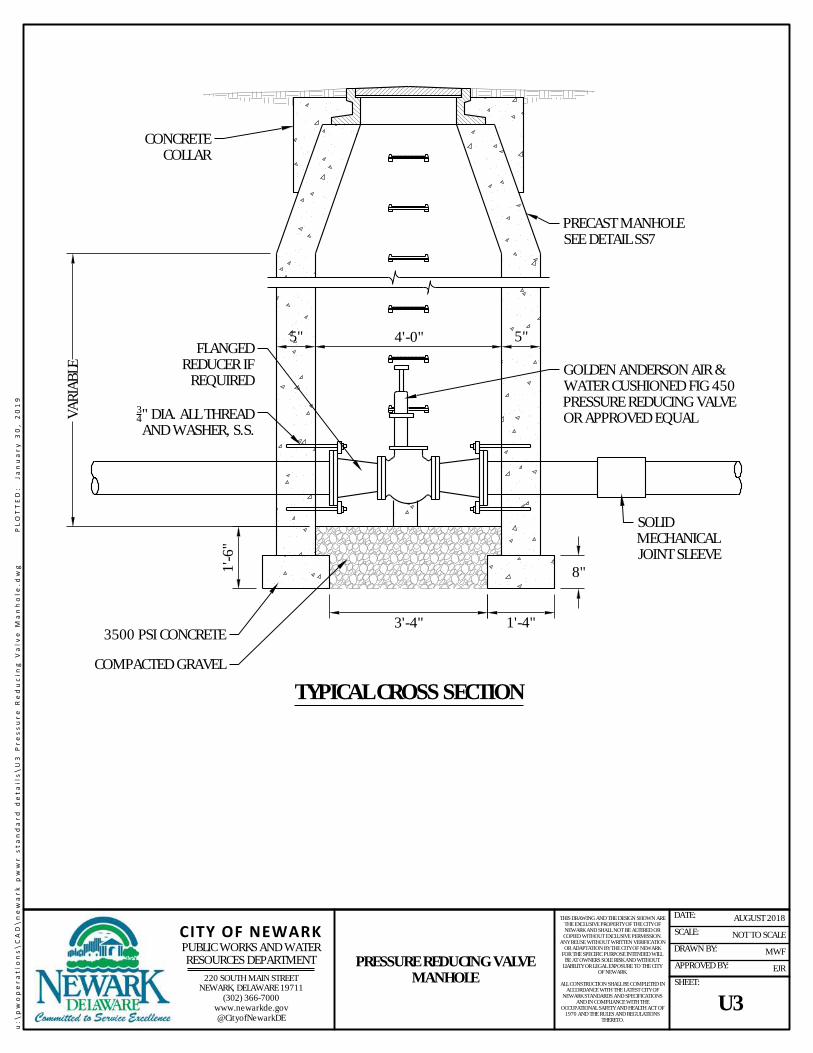
GOLDEN ANDERSON AIR &WATER CUSHIONED FIG 450PRESSURE REDUCING VALVEOR APPROVED EQUAL
FLANGEDREDUCER IF
REQUIRED
3500 PSI CONCRETE3'-4" 1'-4"
8"1'-6
"
VARI
ABLE
4'-0"
PRECAST MANHOLESEE DETAIL SS7
5"5"
34" DIA. ALL THREADAND WASHER, S.S.
SOLIDMECHANICALJOINT SLEEVE
COMPACTED GRAVEL
TYPICAL CROSS SECTION
CONCRETECOLLAR
u:\p
wop
erat
ions
\CAD
\new
ark
pww
r sta
ndar
d de
tails
\U3
Pres
sure
Red
ucin
g Va
lve
Man
hole
.dw
g
PLO
TTED
: Ja
nuar
y 30
, 201
9
220 SOUTH MAIN STREETNEWARK, DELAWARE 19711
(302) 366-7000www.newarkde.gov@CityofNewarkDE
CITY OF NEWARKPUBLIC WORKS AND WATERRESOURCES DEPARTMENT PRESSURE REDUCING VALVE
MANHOLE
THIS DRAWING AND THE DESIGN SHOWN ARETHE EXCLUSIVE PROPERTY OF THE CITY OFNEWARK AND SHALL NOT BE ALTERED OR
COPIED WITHOUT EXCLUSIVE PERMISSION.ANY REUSE WITHOUT WRITTEN VERIFICATION
OR ADAPTATION BY THE CITY OF NEWARKFOR THE SPECIFIC PURPOSE INTENDED WILL
BE AT OWNERS SOLE RISK AND WITHOUTLIABILITY OR LEGAL EXPOSURE TO THE CITY
OF NEWARK.
ALL CONSTRUCTION SHALL BE COMPLETED INACCORDANCE WITH THE LATEST CITY OF
NEWARK STANDARDS AND SPECIFICATIONSAND IN COMPLIANCE WITH THE
OCCUPATIONAL SAFETY AND HEALTH ACT OF1970 AND THE RULES AND REGULATIONS
THERETO.
NOT TO SCALE
MWF
EJR
AUGUST 2018DATE:
SCALE:
DRAWN BY:
APPROVED BY:
SHEET:
U3

NOTE:1. THE MINIMUM DIAMETER OF AN INSIDE DROP MANHOLE SHALL BE 60". IF THE DIAMETER OF THE PROPOSED SANITARY SEWER INFLOW PIPE
IS GREATER THAN 8" OR MULTIPLE DROP CONNECTIONS ARE PROPOSED, MANHOLE SHALL BE 72" IN DIAMETER. WHEN CONNECTING TO ANEXISTING MANHOLE LESS THAN 60", THE MANHOLE SHALL BE REPLACED.
2. THE USE OF A FORCE MAIN INSIDE DROP MANHOLE SHALL BE AT THE SOLE DISCRETION OF THE PUBLIC WORKS AND WATER RESOURCESDIRECTOR OR THEIR DESIGNEE.
A-LOK OR APPROVED EQUALPIPE-TO-MANHOLE ADAPTOR
STAINLESS STEEL STRAPSUPPORTS & ANCHORS,SECURELY ANCHOREDTO MANHOLE WALLS
CHANNEL HEIGHT TO 1/2 PIPE DIA.SLOPE CHANNEL 1/4" PER FT.
MIN RATIO SIZE: CONNECTION& RISER PIPE SIZE TO BE 2XLARGER THAN FORCE MAIN
INFLOW PIPE AREA
SDR-21 TEE
MANHOLE
SDR-2190° BEND
8" AASHTO #57 STONE
60" MIN. DIA.(SEE NOTE 1)
FORCE MAININFLOW PIPE
FLOW
FLOW
CROSS SECTION A-A
AA
MANHOLE
SEWER LINEFLOW CHANNELANGLED TOWARD FLOW
RISER PIPE
FORCE MAIN INFLOW PIPE
REDUCER5'-0"
SDR-21 VENTED, SCREW-TYPEREMOVABLE CAP
SDR-21
SDR-
21
u:\p
wop
erat
ions
\CAD
\new
ark
pww
r sta
ndar
d de
tails
\U4
Forc
e M
ain
insid
e Dr
op M
anho
le D
etai
l.dw
g
PLO
TTED
: Ja
nuar
y 30
, 201
9
220 SOUTH MAIN STREETNEWARK, DELAWARE 19711
(302) 366-7000www.newarkde.gov@CityofNewarkDE
CITY OF NEWARKPUBLIC WORKS AND WATERRESOURCES DEPARTMENT FORCE MAIN INSIDE DROP
MANHOLE DETAIL
THIS DRAWING AND THE DESIGN SHOWN ARETHE EXCLUSIVE PROPERTY OF THE CITY OFNEWARK AND SHALL NOT BE ALTERED OR
COPIED WITHOUT EXCLUSIVE PERMISSION.ANY REUSE WITHOUT WRITTEN VERIFICATION
OR ADAPTATION BY THE CITY OF NEWARKFOR THE SPECIFIC PURPOSE INTENDED WILL
BE AT OWNERS SOLE RISK AND WITHOUTLIABILITY OR LEGAL EXPOSURE TO THE CITY
OF NEWARK.
ALL CONSTRUCTION SHALL BE COMPLETED INACCORDANCE WITH THE LATEST CITY OF
NEWARK STANDARDS AND SPECIFICATIONSAND IN COMPLIANCE WITH THE
OCCUPATIONAL SAFETY AND HEALTH ACT OF1970 AND THE RULES AND REGULATIONS
THERETO.
NOT TO SCALE
MWF
EJR
AUGUST 2018DATE:
SCALE:
DRAWN BY:
APPROVED BY:
SHEET:
U4

NOTE:1. LINE MANHOLE INTERIOR WITH A 3 COAT SYSTEM MODIFIED POLYAMINE EPOXY BY TNEMEC OR APPROVED EQUAL.
A-LOK OR APPROVED EQUALPIPE-TO-MANHOLE ADAPTOR
MANHOLE
8" AASHTO#57 STONE
48" MIN. DIA.
FLOW FLOW
CROSS SECTION A-A
AA
MANHOLE
GRAVITY SEWER LINE
FORCE MAININFLOW PIPE
STANDARD MANHOLE STEPS
FORCE MAININFLOW PIPE
2'MAX.
MINIMUM RATIO SIZE:MANHOLE CONNECTIONPIPE SIZE WILL BE 2.0 XFORCE MAIN PIPE AREA
FLOW
MINIMUM RATIO SIZE:MANHOLE CONNECTIONPIPE SIZE WILL BE 2.0 XFORCE MAIN PIPE AREA
LINE MANHOLE INTERIOR(SEE NOTE 1)
u:\p
wop
erat
ions
\CAD
\new
ark
pww
r sta
ndar
d de
tails
\U5
Forc
e M
ain
Disc
harg
e to
Man
hole
.dw
g
PLO
TTED
: Ja
nuar
y 30
, 201
9
220 SOUTH MAIN STREETNEWARK, DELAWARE 19711
(302) 366-7000www.newarkde.gov@CityofNewarkDE
CITY OF NEWARKPUBLIC WORKS AND WATERRESOURCES DEPARTMENT FORCE MAIN DISCHARGE TO
MANHOLE
THIS DRAWING AND THE DESIGN SHOWN ARETHE EXCLUSIVE PROPERTY OF THE CITY OFNEWARK AND SHALL NOT BE ALTERED OR
COPIED WITHOUT EXCLUSIVE PERMISSION.ANY REUSE WITHOUT WRITTEN VERIFICATION
OR ADAPTATION BY THE CITY OF NEWARKFOR THE SPECIFIC PURPOSE INTENDED WILL
BE AT OWNERS SOLE RISK AND WITHOUTLIABILITY OR LEGAL EXPOSURE TO THE CITY
OF NEWARK.
ALL CONSTRUCTION SHALL BE COMPLETED INACCORDANCE WITH THE LATEST CITY OF
NEWARK STANDARDS AND SPECIFICATIONSAND IN COMPLIANCE WITH THE
OCCUPATIONAL SAFETY AND HEALTH ACT OF1970 AND THE RULES AND REGULATIONS
THERETO.
NOT TO SCALE
MWF
EJR
AUGUST 2018DATE:
SCALE:
DRAWN BY:
APPROVED BY:
SHEET:
U5

FLOW
FLOW
NEW FLOW CHANNELPRECAST CONCRETEMANHOLE
CHAN
NEL
CHANNEL FLOW
8"4"
6" TYP.6" TYP.
EXISTINGPIPE
REMOVE TOP HALFOF EXISTING PIPE
NEW FLOW CHANNEL TOTOP OF PIPE DIAMETER
CONCRETE BELOW SPRINGLINE OF PIPE 4,000 PSI
12" THICK LAYER OFSTONE BEDDING
(SEE NOTE 1)
(SEE NOTE 2)
SPRING LINE OF PIPE
NEW FLOW CHANNEL TOTOP OF PIPE DIAMETER
WALL AREA BETWEEN EXISTINGPIPE AND DOGHOUSE OPENINGS
SHALL BE FILLED WITH CONCRETE.
PLAN
TYPICAL CROSS SECTION
NOTES:1. STONE BEDDING SHALL CONFORM TO THE CITY OF NEWARK STANDARD SPECIFICATIONS FOR CONSTRUCTION.2. IF MANHOLE EXCAVATION BOTTOM IS IN UNSUITABLE MATERIAL, SUITABLE FILL MATERIAL AND MIRAFI 140N FILTER FABRIC, OR APPROVED
EQUAL WILL BE REQUIRED PRIOR TO PLACEMENT OF BEDDING.
14"/FT. SLOPE
PRECAST MANHOLERISER SECTION
48" MIN. DIA.
u:\p
wop
erat
ions
\CAD
\new
ark
pww
r sta
ndar
d de
tails
\U6
Dogh
ouse
Man
hole
Det
ail.d
wg
PL
OTT
ED:
Janu
ary
30, 2
019
220 SOUTH MAIN STREETNEWARK, DELAWARE 19711
(302) 366-7000www.newarkde.gov@CityofNewarkDE
CITY OF NEWARKPUBLIC WORKS AND WATERRESOURCES DEPARTMENT
DOGHOUSE MANHOLE DETAIL
THIS DRAWING AND THE DESIGN SHOWN ARETHE EXCLUSIVE PROPERTY OF THE CITY OFNEWARK AND SHALL NOT BE ALTERED OR
COPIED WITHOUT EXCLUSIVE PERMISSION.ANY REUSE WITHOUT WRITTEN VERIFICATION
OR ADAPTATION BY THE CITY OF NEWARKFOR THE SPECIFIC PURPOSE INTENDED WILL
BE AT OWNERS SOLE RISK AND WITHOUTLIABILITY OR LEGAL EXPOSURE TO THE CITY
OF NEWARK.
ALL CONSTRUCTION SHALL BE COMPLETED INACCORDANCE WITH THE LATEST CITY OF
NEWARK STANDARDS AND SPECIFICATIONSAND IN COMPLIANCE WITH THE
OCCUPATIONAL SAFETY AND HEALTH ACT OF1970 AND THE RULES AND REGULATIONS
THERETO.
NOT TO SCALE
MWF
EJR
AUGUST 2018DATE:
SCALE:
DRAWN BY:
APPROVED BY:
SHEET:
U6

FILL WITH FLOWABLE FILLMATERIAL AND COMPACT
(SEE NOTE 1)
UNPAVED PAVED
REMOVE MANHOLE FRAME,COVER & CONE SECTION (TYP.)
OR 2' BELOW GRADE MINIMUM
BACKFILL WITH BORROW TYPE"C" UP TO 4" BELOW GRADE
TYPICAL CROSS SECTION
BACKFILL WITH BORROW TYPE "C",COMPACTED TO 95% OF THEMAXIMUM DRY UNIT WEIGHTACCORDING TO ASTM D1557
BASE COURSE TYPE AND THICKNESSPER DELDOT REQUIREMENT
NON-PAVED RESTORATION ROADWAY RESTORATION
SAW CUT
GROUT PLUG
FILL ENTIRE LENGTH OFPIPE WITH FLOWABLEFILL (SEE NOTE)
GROUT PLUG PLUG PIPE ENDS
FILL ENTIRE LENGTH OFPIPE WITH FLOWABLE FILL
(SEE NOTE)
NOTE:1. FLOWABLE FILL SHALL BE AS DEFINED BY THE AMERICAN CONCRETE INSTITUTE (ACI) AS A SELF COMPACTING CEMENTITIOUS MATERIAL THAT
IS IN A FLOWABLE STATE AT PLACEMENT AND HAS A COMPRESSIVE STRENGTH OF 8.3 MPa (1,200 lb/in2) OR MORE AT 28 DAYS.
u:\p
wop
erat
ions
\CAD
\new
ark
pww
r sta
ndar
d de
tails
\U7
Aban
done
d M
anho
le D
etai
l.dw
g
PLO
TTED
: Ja
nuar
y 30
, 201
9
220 SOUTH MAIN STREETNEWARK, DELAWARE 19711
(302) 366-7000www.newarkde.gov@CityofNewarkDE
CITY OF NEWARKPUBLIC WORKS AND WATERRESOURCES DEPARTMENT ABANDONED MANHOLE
DETAIL
THIS DRAWING AND THE DESIGN SHOWN ARETHE EXCLUSIVE PROPERTY OF THE CITY OFNEWARK AND SHALL NOT BE ALTERED OR
COPIED WITHOUT EXCLUSIVE PERMISSION.ANY REUSE WITHOUT WRITTEN VERIFICATION
OR ADAPTATION BY THE CITY OF NEWARKFOR THE SPECIFIC PURPOSE INTENDED WILL
BE AT OWNERS SOLE RISK AND WITHOUTLIABILITY OR LEGAL EXPOSURE TO THE CITY
OF NEWARK.
ALL CONSTRUCTION SHALL BE COMPLETED INACCORDANCE WITH THE LATEST CITY OF
NEWARK STANDARDS AND SPECIFICATIONSAND IN COMPLIANCE WITH THE
OCCUPATIONAL SAFETY AND HEALTH ACT OF1970 AND THE RULES AND REGULATIONS
THERETO.
NOT TO SCALE
MWF
EJR
AUGUST 2018DATE:
SCALE:
DRAWN BY:
APPROVED BY:
SHEET:
U7

2'-0" MIN. 1'-0"1'-0"
4'-0" MIN.NEW CUT TO BE MADEAT TIME PAVEMENT ISREPAIRED - 4'-0" MIN.
3" TYPE "C" HOT MIXPLACED AND COMPACTEDIN TWO LIFTS
BACKFILL AS REQUIREDBY UTILITY TYPE
8" CLASS A6-HOURCONCRETE
SERVICE LATERAL /SANITARY MAIN /WATER MAIN /FIRE HYDRANT
NOTES:1. CONTRACTOR SHALL VERIFY DEPTH AND TYPE OF EXISTING PAVING COURSES. IF EXISTING SECTION IS GREATER THAN MINIMUM
SPECIFICATION, MATCH EXISTING SECTION. PAVING SECTION SUBJECT TO APPROVAL BY CITY OF NEWARK PUBLIC WORKS DEPARTMENT.2. THIS DETAIL SHALL BE USED FOR ALL TRENCHES THAT ARE PERPENDICULAR TO THE ROADWAYS FOR SERVICE LATERALS, WATER MAINS, AND
FIRE HYDRANTS.3. THIS DETAIL SHALL BE USED FOR ALL TRENCHES IN INTERSECTIONS OF CITY OWNED STREETS THAT ARE LOCATED IN THE ENTIRE RADIUS OF
THE CURB AT THE INTERSECTION.
TYPICAL CROSS SECTION
u:\p
wop
erat
ions
\CAD
\new
ark
pww
r sta
ndar
d de
tails
\U8
Util
ity T
renc
h Ro
ad C
ross
ing
Deta
il.dw
g
PLO
TTED
: Ja
nuar
y 30
, 201
9
220 SOUTH MAIN STREETNEWARK, DELAWARE 19711
(302) 366-7000www.newarkde.gov@CityofNewarkDE
CITY OF NEWARKPUBLIC WORKS AND WATERRESOURCES DEPARTMENT UTILITY TRENCH ROAD
CROSSING DETAIL
THIS DRAWING AND THE DESIGN SHOWN ARETHE EXCLUSIVE PROPERTY OF THE CITY OFNEWARK AND SHALL NOT BE ALTERED OR
COPIED WITHOUT EXCLUSIVE PERMISSION.ANY REUSE WITHOUT WRITTEN VERIFICATION
OR ADAPTATION BY THE CITY OF NEWARKFOR THE SPECIFIC PURPOSE INTENDED WILL
BE AT OWNERS SOLE RISK AND WITHOUTLIABILITY OR LEGAL EXPOSURE TO THE CITY
OF NEWARK.
ALL CONSTRUCTION SHALL BE COMPLETED INACCORDANCE WITH THE LATEST CITY OF
NEWARK STANDARDS AND SPECIFICATIONSAND IN COMPLIANCE WITH THE
OCCUPATIONAL SAFETY AND HEALTH ACT OF1970 AND THE RULES AND REGULATIONS
THERETO.
NOT TO SCALE
MWF
EJR
JANUARY 2019DATE:
SCALE:
DRAWN BY:
APPROVED BY:
SHEET:
U8

PIPE DIA. + 2' 1'-0"1'-0"
4'-0" MIN.
1'-0"1'-0"
8" TYPE "B" HOT MIXPLACED IN 4" LIFTS
2" TYPE "C" HOT MIX
NOTES:1. CONTRACTOR SHALL VERIFY DEPTH AND TYPE OF EXISTING PAVING COURSES AND PROVIDE AN ADDITIONAL INCH DEPTH FOR EACH COURSE.
PAVING SECTION SUBJECT TO APPROVAL BY CITY OF NEWARK PUBLIC WORKS AND WATER RESOURCES DEPARTMENT.2. THE USE OF EXCAVATED DIRT TO 1'-0" ABOVE THE PROPOSED WATER MAIN SHALL BE SUBJECT TO THE APPROVAL OF THE INSPECTOR.
TYPICAL CROSS SECTION
NEW CUT TO BE MADEAT TIME PAVEMENT IS
REPAIRED (TYP.)
BACKFILL AS REQUIREDBY UTILITY TYPE
SERVICE LATERAL /SANITARY MAIN /WATER MAIN /FIRE HYDRANT
u:\p
wop
erat
ions
\CAD
\new
ark
pww
r sta
ndar
d de
tails
\U9
Long
itudi
nal T
renc
h De
tail
for C
ity R
oadw
ay.d
wg
PL
OTT
ED:
Janu
ary
30, 2
019
220 SOUTH MAIN STREETNEWARK, DELAWARE 19711
(302) 366-7000www.newarkde.gov@CityofNewarkDE
CITY OF NEWARKPUBLIC WORKS AND WATERRESOURCES DEPARTMENT LONGITUDINAL TRENCH
DETAIL FOR CITY ROADWAY
THIS DRAWING AND THE DESIGN SHOWN ARETHE EXCLUSIVE PROPERTY OF THE CITY OFNEWARK AND SHALL NOT BE ALTERED OR
COPIED WITHOUT EXCLUSIVE PERMISSION.ANY REUSE WITHOUT WRITTEN VERIFICATION
OR ADAPTATION BY THE CITY OF NEWARKFOR THE SPECIFIC PURPOSE INTENDED WILL
BE AT OWNERS SOLE RISK AND WITHOUTLIABILITY OR LEGAL EXPOSURE TO THE CITY
OF NEWARK.
ALL CONSTRUCTION SHALL BE COMPLETED INACCORDANCE WITH THE LATEST CITY OF
NEWARK STANDARDS AND SPECIFICATIONSAND IN COMPLIANCE WITH THE
OCCUPATIONAL SAFETY AND HEALTH ACT OF1970 AND THE RULES AND REGULATIONS
THERETO.
NOT TO SCALE
MWF
EJR
JANUARY 2019DATE:
SCALE:
DRAWN BY:
APPROVED BY:
SHEET:
U9

TYPICAL CROSS SECTION
H
4/3 x O.D. MIN.
1/2 O.D. IN-SITU /LOWER SIDE
IN-SITU /LOWER SIDE
1/3 x O.D. MIN.
FOUNDATIONPIPE BEDDING, 3"MINIMUM (EXCEPTON ROCK). MIDDLE
13 LOOSELY PLACED /
UNCOMPACTED -SEE TABLES
IN-SITU SOILS
IN-SITU SOILS
O.D. MIN.
FINAL BACKFILLPER PROJECT
REQUIREMENTS
TRENCH INSTALLATIONPIPE DIA.
(IN)OUTSIDEDIA. (IN)
12 O.D.(FEET)
43 O.D.(FEET)
12 16.5 0.7 1.815 19.5 0.8 2.2
18 23.0 1.0 2.621 26.5 1.1 2.924 30.0 1.3 3.327 33.5 1.4 3.730 37.0 1.5 4.136 44.0 1.8 4.942 51.0 2.1 5.748 58.0 2.4 6.454 65.0 2.7 7.260 72.0 3.0 8.066 79.0 3.3 8.872 86.0 3.6 9.578 93.0 3.9 10.384 100.0 4.2 11.1
90 107.0 4.5 11.996 114.0 4.8 12.6
102 121.0 5.0 13.4108 128.0 5.3 14.2114 135.0 5.6 15.0120 142.0 5.9 15.7
DIMENSIONS BASED ON B WALL.ADD 1.5" TO O.D. FOR C WALL.
STANDARD INSTALLATION SOILS AND MINIMUM COMPACTION REQUIREMENTS
BEDDING THICKNESS BEDDING AND HAUNCH LOWER SIDE BACKFILL/FILLO.D. / 24 MINIMUM, NOT LESS
THAN 3". IF ROCKFOUNDATION, USE O.D. / 12
MINIMUM, NOT LESS THAN 6"
90% CATEGORY I OR 95%CATEGORY II
85% CATEGORY I, 90%CATEGORY II, OR 95%
CATEGORY III
MATERIAL ANDCONSTRUCTION METHODS INACCORDANCE WITH PROJECT
SPECIFICATION.MATERIAL PLACEMENT SHALL BE IN 8-INCH LOOSE LIFTS AND COMPACTED IN ACCORDANCE WITH AASHTO T 99.
REPRESENTATIVE SOIL TYPES
SIDD USCS AASHTOCATEGORY I - GRAVELLY SAND SW, SP, GW, GP A1, A3
CATEGORY II - SANDY SILTGM, SM, ML, ALSO GC, SC
WITH LESS THAN 20% PASSING#200 SIEVE
A2, A4
CATEGORY III - SILTY CLAY SW, SP, GW, GP A1, A3
u:\p
wop
erat
ions
\CAD
\new
ark
pww
r sta
ndar
d de
tails
\U10
Rei
nfor
ced
Conc
rete
Pip
e Tr
ench
Det
ail.d
wg
PL
OTT
ED:
Janu
ary
30, 2
019
220 SOUTH MAIN STREETNEWARK, DELAWARE 19711
(302) 366-7000www.newarkde.gov@CityofNewarkDE
CITY OF NEWARKPUBLIC WORKS AND WATERRESOURCES DEPARTMENT REINFORCED CONCRETE PIPE
TRENCH DETAIL
THIS DRAWING AND THE DESIGN SHOWN ARETHE EXCLUSIVE PROPERTY OF THE CITY OFNEWARK AND SHALL NOT BE ALTERED OR
COPIED WITHOUT EXCLUSIVE PERMISSION.ANY REUSE WITHOUT WRITTEN VERIFICATION
OR ADAPTATION BY THE CITY OF NEWARKFOR THE SPECIFIC PURPOSE INTENDED WILL
BE AT OWNERS SOLE RISK AND WITHOUTLIABILITY OR LEGAL EXPOSURE TO THE CITY
OF NEWARK.
ALL CONSTRUCTION SHALL BE COMPLETED INACCORDANCE WITH THE LATEST CITY OF
NEWARK STANDARDS AND SPECIFICATIONSAND IN COMPLIANCE WITH THE
OCCUPATIONAL SAFETY AND HEALTH ACT OF1970 AND THE RULES AND REGULATIONS
THERETO.
NOT TO SCALE
MWF
EJR
AUGUST 2018DATE:
SCALE:
DRAWN BY:
APPROVED BY:
SHEET:
U10

NOTES:A. THRUST COLLARS SHALL BE INSTALLED AT ALL TRANSITIONS TO OTHER PIPE MATERIALS.B. HIGH DENSITY POLYETHYLENE (HDPE) FITTINGS SHALL MEET THE REQUIREMENTS OF AWWA C906.C. MECHANICAL FITTINGS SHALL BE SPECIFICALLY DESIGNED FOR USE WITH HDPE PIPE.D. INSTALL STAINLESS STEEL INTERNAL STIFFENER IN THE END OF THE HDPE PIPE WHEN HDPE PIPE IS INSERTED INTO THE BELL END OF
NON-HDPE PIPE, VALVE, FITTING, OR INTO THE HUB OF A MECHANICAL COUPLING.E. INTERNAL STIFFENER CAN BE WEDGE TYPE OR SOLID BODY. STIFFENER WILL BE RATED FOR DR AND ID OF PIPE. FOR WATER, 304 OR 316
STAINLESS STEEL IS ALLOWED. FOR WASTEWATER, 316 SS IS REQUIRED.F. MECHANICAL JOINT ADAPTERS SHALL BE PE4710 AND CAN BE MADE TO ASTM D 3261. IF MACHINED, ADAPTERS MUST MEET THE
REQUIREMENTS OF ASTM F 2206. ADAPTERS SHALL HAVE A PRESSURE RATING EQUAL TO THE PIPE.G. EXTERNAL RESTRAINT DEVICES ARE NOT ALLOWED.
CONCRETE THRUST COLLAR
FUSED WALL ANCHOROR FLEX RESTRAINT
1' MIN.5' MAX.
HDPE PIPE
RESTRAINED MJ ADAPTERWITH STEEL PIPESTIFFENER AND KIT
MJ DI PIPE / SLEEVE /VALVE / FITTING
HDPE TO DUCTILE IRON TRANSITION ASSEMBLY(4 TO 32 INCH ONLY)
1' MIN.5' MAX.
CONCRETE THRUST COLLAR
FUSED WALL ANCHOROR FLEX RESTRAINT
HDPE PIPE PVC ORDIP
BELL MJ ADAPTER WITHMECHANICAL RESTRAINT KIT
HDPE TO PVC OR DUCTILE IRON TRANSITION ASSEMBLY(4 TO 32 INCH ONLY)
u:\p
wop
erat
ions
\CAD
\new
ark
pww
r sta
ndar
d de
tails
\U11
Tra
nsiti
on fr
om H
DPE
to D
IP.d
wg
PL
OTT
ED:
Janu
ary
30, 2
019
220 SOUTH MAIN STREETNEWARK, DELAWARE 19711
(302) 366-7000www.newarkde.gov@CityofNewarkDE
CITY OF NEWARKPUBLIC WORKS AND WATERRESOURCES DEPARTMENT TRANSITION FROM HDPE TO
DIP
THIS DRAWING AND THE DESIGN SHOWN ARETHE EXCLUSIVE PROPERTY OF THE CITY OFNEWARK AND SHALL NOT BE ALTERED OR
COPIED WITHOUT EXCLUSIVE PERMISSION.ANY REUSE WITHOUT WRITTEN VERIFICATION
OR ADAPTATION BY THE CITY OF NEWARKFOR THE SPECIFIC PURPOSE INTENDED WILL
BE AT OWNERS SOLE RISK AND WITHOUTLIABILITY OR LEGAL EXPOSURE TO THE CITY
OF NEWARK.
ALL CONSTRUCTION SHALL BE COMPLETED INACCORDANCE WITH THE LATEST CITY OF
NEWARK STANDARDS AND SPECIFICATIONSAND IN COMPLIANCE WITH THE
OCCUPATIONAL SAFETY AND HEALTH ACT OF1970 AND THE RULES AND REGULATIONS
THERETO.
NOT TO SCALE
MWF
EJR
AUGUST 2018DATE:
SCALE:
DRAWN BY:
APPROVED BY:
SHEET:
U11

CL
FILTER FABRIC
10' WIDE TURF TRAILCENTERED OVER PIPE(S)
20' EASEMENT
8" GRADED AGGREGATE BASE COURSE(COMPACTED)
4" TOPSOIL AND STABILIZED VEGETATION
UTILITY PIPE(S) CENTEREDWITHIN EASEMENT
CL
FILTER FABRIC
10' WIDE TURF TRAILCENTERED OVER PIPE(S)
40' EASEMENT
8" GRADED AGGREGATE BASE COURSE(COMPACTED)
4" TOPSOIL AND STABILIZED VEGETATION
NOTES:1. FILTER FABRIC SHALL BE MIRAFI 600X OR APPROVED EQUAL. FILTER FABRIC SHALL BE REQUIRED UNLESS OTHERWISE DIRECTED BY THE
ENGINEER.2. IF WATER AND SEWER PIPES ARE BOTH LOCATED WITHIN THE EASEMENT THE TURF TRAIL SHALL BE LOCATED BETWEEN THE PIPES. PIPES
SHALL BE SEPERATED BY A MINIMUM OF 10-FEET FROM EACH OTHER AND A MINIMUM OF 10-FEET FROM THE EDGE OF THE EASEMENT.
UTILITY PIPE(S) CENTEREDWITHIN EASEMENT
40' WIDE EASEMENT
20' WIDE EASEMENT
u:\p
wop
erat
ions
\CAD
\new
ark
pww
r sta
ndar
d de
tails
\U12
Util
ity T
urf T
rail
Deta
il.dw
g
PLO
TTED
: Ja
nuar
y 30
, 201
9
220 SOUTH MAIN STREETNEWARK, DELAWARE 19711
(302) 366-7000www.newarkde.gov@CityofNewarkDE
CITY OF NEWARKPUBLIC WORKS AND WATERRESOURCES DEPARTMENT
UTILITY TURF TRAIL DETAIL
THIS DRAWING AND THE DESIGN SHOWN ARETHE EXCLUSIVE PROPERTY OF THE CITY OFNEWARK AND SHALL NOT BE ALTERED OR
COPIED WITHOUT EXCLUSIVE PERMISSION.ANY REUSE WITHOUT WRITTEN VERIFICATION
OR ADAPTATION BY THE CITY OF NEWARKFOR THE SPECIFIC PURPOSE INTENDED WILL
BE AT OWNERS SOLE RISK AND WITHOUTLIABILITY OR LEGAL EXPOSURE TO THE CITY
OF NEWARK.
ALL CONSTRUCTION SHALL BE COMPLETED INACCORDANCE WITH THE LATEST CITY OF
NEWARK STANDARDS AND SPECIFICATIONSAND IN COMPLIANCE WITH THE
OCCUPATIONAL SAFETY AND HEALTH ACT OF1970 AND THE RULES AND REGULATIONS
THERETO.
NOT TO SCALE
MWF
EJR
NOVEMBER 2018DATE:
SCALE:
DRAWN BY:
APPROVED BY:
SHEET:
U12

PIPE O.D. +2'-0" MIN.
CR-6 PLACED LOOSELYAND COMPACTED1 IN
8" (MAX.) LIFTS
SELECT BORROW OR NATIVE SOIL2
COMPACTED1 IN 8" (MAX.) LIFTS
WATER MAIN / SERVICE3
NOTES:1. COMPACTION TO BE ACHIEVED USING MECHANICAL TAMPER OF VIBRATORY COMPACTOR.2. USE OF NATIVE SOIL SHALL BE AT THE SOLE DISCRETION OF THE PUBLIC WORKS AND WATER RESOURCES DEPARTMENT DIRECTOR OR THEIR
DESIGNEE.3. WATER MAIN SHALL BE WRAPPED IN POLYETHYLENE ENCASEMENT AS REQUIRED BY THE CITY WATER AND WASTEWATER STANDARDS AND
SPECIFICATIONS.4. FOR PAVED AREAS, THE PAVEMENT SECTION REQUIRED IS DETERMINED BY THE TYPE OF ROAD AND WHETHER THE TRENCH IS LONGITUDINAL
OR PERPENDICULAR TO THE ROAD. CONTRACTOR TO VERIFY EXISTING PAVEMENT CROSS SECTION.5. FOR UNPAVED AREAS, VEGETATION SHALL BE RESTORED TO EXISTING CONDITIONS UNLESS OTHERWISE DIRECTED.
TYPICAL CROSS SECTION
NO. 57 STONE BEDDING
6" TOPSOIL ANDSTABILIZED VEGETATION
PAVED UNPAVED
6"
6"
6"
NO. 57 STONE BEDDING
INITIAL BACKFILL BEFORE COMPACTION(SELECT BORROW OR NATIVE SOIL2)
INITIAL BACKFILL BEFORECOMPACTION (CR-6)
PAVEMENT SECTION AS REQUIRED
SELECT BORROW OR NATIVE SOIL2
1'-0"MIN.
1'-0"MIN.
PIPEO.D.
u:\p
wop
erat
ions
\CAD
\new
ark
pww
r sta
ndar
d de
tails
\W1
Wat
er T
renc
h De
tail.
dwg
PL
OTT
ED:
Janu
ary
30, 2
019
220 SOUTH MAIN STREETNEWARK, DELAWARE 19711
(302) 366-7000www.newarkde.gov@CityofNewarkDE
CITY OF NEWARKPUBLIC WORKS AND WATERRESOURCES DEPARTMENT
WATER TRENCH DETAIL
THIS DRAWING AND THE DESIGN SHOWN ARETHE EXCLUSIVE PROPERTY OF THE CITY OFNEWARK AND SHALL NOT BE ALTERED OR
COPIED WITHOUT EXCLUSIVE PERMISSION.ANY REUSE WITHOUT WRITTEN VERIFICATION
OR ADAPTATION BY THE CITY OF NEWARKFOR THE SPECIFIC PURPOSE INTENDED WILL
BE AT OWNERS SOLE RISK AND WITHOUTLIABILITY OR LEGAL EXPOSURE TO THE CITY
OF NEWARK.
ALL CONSTRUCTION SHALL BE COMPLETED INACCORDANCE WITH THE LATEST CITY OF
NEWARK STANDARDS AND SPECIFICATIONSAND IN COMPLIANCE WITH THE
OCCUPATIONAL SAFETY AND HEALTH ACT OF1970 AND THE RULES AND REGULATIONS
THERETO.
NOT TO SCALE
MWF
EJR
JANUARY 2019DATE:
SCALE:
DRAWN BY:
APPROVED BY:
SHEET:
W1

UNDISTURBED SOIL
WASHED STONE OR DEL. #57PLACED AROUND WEEP HOLES
PER SPECIFICATIONS
6" DIP CLASS 52 PIPE
3500 PSI CONC. BUTTRESS
3/4" S.S. THREADED ROD RESTRAINTAND RESTRAINED JOINTS
VALVE BOX COVER "WATER"
40 MIL POLY COVEROVER STONE
MUELLER A423 FIREHYDRANT WITH 250/HSHYDRANT SHOE
WEEP HOLE S SHALL BE KEPTCLEAN OF CONCRETE
3/4" S.S THREADED ROD RESTRAINTAND RESTRAINED JOINTS
SAFETY BREAKAWAY FLANGE
COMPACTED SELECTBACKFILL MATERIAL
INTEGRATED HIGH-SECURITYCHECK VALVE
42"MIN.
COVER
18"MIN.
AA
6" MIN.
12" MIN.
12" MIN.
12" MIN.
SECTION A-A
FINISHED GRADE
2"
DISTANCE FROM CENTER OF HYDRANT TOFACE OF CURB NOT GREATER THAN 9 FT.
MUELLER H-10360 CAST IRONSCREW TYPE VALVE BOX, OR
APPROVED EQUALMUELLER MODEL A-2360
6" M.J. GATE VALVEM.J. HYDRANT TEE
3500 PSI CONC. BUTTRESS
12" MIN.
3500 PSI CONC. BUTTRESS
NOTES:1. HYDRANT TO BE PLACED WITH STEAMER CONNECTION FACING STREET.2. MEGA-LUG REQUIRED AT VALVE (ON HYDRANT SIDE ONLY IF HYDRANT TEE IS UTILIZED) AND AT HYDRANT.
STEAMER CONNECTION(51
4" DIA. NST)
u:\p
wop
erat
ions
\CAD
\new
ark
pww
r sta
ndar
d de
tails
\W2
Stan
dard
Fire
Hyd
rant
Inst
alla
tion.
dwg
PL
OTT
ED:
Janu
ary
30, 2
019
220 SOUTH MAIN STREETNEWARK, DELAWARE 19711
(302) 366-7000www.newarkde.gov@CityofNewarkDE
CITY OF NEWARKPUBLIC WORKS AND WATERRESOURCES DEPARTMENT STANDARD FIRE HYDRANT
INSTALLATION
THIS DRAWING AND THE DESIGN SHOWN ARETHE EXCLUSIVE PROPERTY OF THE CITY OFNEWARK AND SHALL NOT BE ALTERED OR
COPIED WITHOUT EXCLUSIVE PERMISSION.ANY REUSE WITHOUT WRITTEN VERIFICATION
OR ADAPTATION BY THE CITY OF NEWARKFOR THE SPECIFIC PURPOSE INTENDED WILL
BE AT OWNERS SOLE RISK AND WITHOUTLIABILITY OR LEGAL EXPOSURE TO THE CITY
OF NEWARK.
ALL CONSTRUCTION SHALL BE COMPLETED INACCORDANCE WITH THE LATEST CITY OF
NEWARK STANDARDS AND SPECIFICATIONSAND IN COMPLIANCE WITH THE
OCCUPATIONAL SAFETY AND HEALTH ACT OF1970 AND THE RULES AND REGULATIONS
THERETO.
NOT TO SCALE
MWF
EJR
AUGUST 2018DATE:
SCALE:
DRAWN BY:
APPROVED BY:
SHEET:
W2

34" X 6' S.S. THREADED ROD
6" S.S. FRICTION CLAMP
18" HIGH X 24" WIDE X 6" THICKPOURED CONCRETE 3500 P.S.I.
6" D.I.P.
3500 P.S.I.CONCRETE
KICKER
6" D.I.P.
PLAN VIEW
SECTION VIEW
u:\p
wop
erat
ions
\CAD
\new
ark
pww
r sta
ndar
d de
tails
\W3
Exist
ing
Fire
Hyd
rant
Tie
Bac
k.dw
g
PLO
TTED
: Ja
nuar
y 30
, 201
9
220 SOUTH MAIN STREETNEWARK, DELAWARE 19711
(302) 366-7000www.newarkde.gov@CityofNewarkDE
CITY OF NEWARKPUBLIC WORKS AND WATERRESOURCES DEPARTMENT EXISTING FIRE HYDRANT
TIE BACK
THIS DRAWING AND THE DESIGN SHOWN ARETHE EXCLUSIVE PROPERTY OF THE CITY OFNEWARK AND SHALL NOT BE ALTERED OR
COPIED WITHOUT EXCLUSIVE PERMISSION.ANY REUSE WITHOUT WRITTEN VERIFICATION
OR ADAPTATION BY THE CITY OF NEWARKFOR THE SPECIFIC PURPOSE INTENDED WILL
BE AT OWNERS SOLE RISK AND WITHOUTLIABILITY OR LEGAL EXPOSURE TO THE CITY
OF NEWARK.
ALL CONSTRUCTION SHALL BE COMPLETED INACCORDANCE WITH THE LATEST CITY OF
NEWARK STANDARDS AND SPECIFICATIONSAND IN COMPLIANCE WITH THE
OCCUPATIONAL SAFETY AND HEALTH ACT OF1970 AND THE RULES AND REGULATIONS
THERETO.
NOT TO SCALE
MWF
EJR
AUGUST 2018DATE:
SCALE:
DRAWN BY:
APPROVED BY:
SHEET:
W3

VARIES FROM CURB FACE
MAI
NTA
IN 4
'-0" M
IN.
VARIABLE
VARIABLE4' MIN. COVER VARIABLE
4' MIN. COVER
NOTES:1. WET TAPPING UNDER NORMAL LINE PRESSURE IS REQUIRED.2. CORPORATION STOPS: MUELLER H-15010, OR APPROVED EQUAL.3. CURB STOPS: MULLER H-15201, H-15209 OR APPROVED EQUAL.4. CURB BOX: MUELLER H-10316, H-10336 OR APPROVED EQUAL.5. CORPORATION STOP AND CURB STOP TO HAVE COMPRESSION FITTINGS. FLARE FITTINGS NOT PERMITTED.6. CURB BOX LID TO BE CAST IRON WITH THE WORD "WATER" CAST INTEGRALLY ON TOP.7. PROVIDE 6" SCREENINGS ABOVE AND BELOW COPPER TUBING.
CURB BOX AND LID
CURB BOXCOMPLETE WITH
STATIONARY ROAD2'-0" LONG
CORPORATIONSTOP
CURB STOP
WATER MAIN BRICK OR CONCRETE BLOCK
SERVICE LINETYPE K SOFT COPPER
ONE CONTINUOUS PIECEFROM CORPORATION STOP
TO CURB STOP REQUIRED
PROVIDE SLACK COPPERFOR PROTECTION AGAINSTPULLING CORPORATIONOUT OF MAIN
ROADWAY
u:\p
wop
erat
ions
\CAD
\new
ark
pww
r sta
ndar
d de
tails
\W4
Stan
dard
Wat
er S
ervi
ce D
etai
l.dw
g
PLO
TTED
: Ja
nuar
y 30
, 201
9
220 SOUTH MAIN STREETNEWARK, DELAWARE 19711
(302) 366-7000www.newarkde.gov@CityofNewarkDE
CITY OF NEWARKPUBLIC WORKS AND WATERRESOURCES DEPARTMENT STANDARD WATER SERVICE
DETAIL
THIS DRAWING AND THE DESIGN SHOWN ARETHE EXCLUSIVE PROPERTY OF THE CITY OFNEWARK AND SHALL NOT BE ALTERED OR
COPIED WITHOUT EXCLUSIVE PERMISSION.ANY REUSE WITHOUT WRITTEN VERIFICATION
OR ADAPTATION BY THE CITY OF NEWARKFOR THE SPECIFIC PURPOSE INTENDED WILL
BE AT OWNERS SOLE RISK AND WITHOUTLIABILITY OR LEGAL EXPOSURE TO THE CITY
OF NEWARK.
ALL CONSTRUCTION SHALL BE COMPLETED INACCORDANCE WITH THE LATEST CITY OF
NEWARK STANDARDS AND SPECIFICATIONSAND IN COMPLIANCE WITH THE
OCCUPATIONAL SAFETY AND HEALTH ACT OF1970 AND THE RULES AND REGULATIONS
THERETO.
NOT TO SCALE
MWF
EJR
AUGUST 2018DATE:
SCALE:
DRAWN BY:
APPROVED BY:
SHEET:
W4

NOTES:
1. ONLY MANUFACTURED VALVE BOX EXTENSIONS SHALL BE ALLOWED.2. VALVE OPERATING NUT MUST BE EXTENDED SO THAT THE DEPTH IS NO GREATER THAN 4' FROM THE SURFACE USING A MANUFACTURER
APPROVED STAINLESS STEEL EXTENSION KIT.3. CURB BOX AND VALVE BOX LID SHALL BE CAST IRON WITH THE WORD "WATER" OR "FIRE" CAST INTEGRALLY ON TOP ACCORDINGLY.4. VALVE BOX LOCATED OUTSIDE OF PAVEMENT OR CONCRETE SIDEWALK SHALL HAVE A CONCRETE COLLAR INSTALLED AS SHOWN UNLESS
OTHERWISE DIRECTED BY THE PUBLIC WORKS AND WATER RESOURCES DEPARTMENT.
SOLID CMU ORBRICK SUPPORT
3" THICK AASHTONO. 57 STONE
SOFT COPPER TUBING TYPE "K"
IN-LINEGATE VALVE
BINGHAM & TAYLOROR TYLER UNION
6850 SERIESSCREW-TYPE
VALVE BOX ORAPPROVED EQUAL
MANUFACTUREDEXTENSION SECTIONS
AS NECESSARYMUELLER H15201 ORH15209 CURB STOP
VALVE OR APPROVEDEQUAL
BINGHAM & TAYLOROR TYLER UNION
6500 SERIESSCREW-TYPE
CURB BOX ORAPPROVED EQUAL
MANUFACTUREDEXTENSION SECTIONS
AS NECESSARY
SOLID CMU ORBRICK SUPPORT
3" THICK AASHTONO. 57 STONE
DIP WATERMAIN
VALVE BOXNOT TO SCALE
CURB BOXNOT TO SCALE
4" MIN.
18" MIN.
3,500 PSICONCRETE
COLLAR
u:\p
wop
erat
ions
\CAD
\new
ark
pww
r sta
ndar
d de
tails
\W5
Stan
dard
Inst
alla
tion
Curb
Box
and
Val
ve B
ox.d
wg
PL
OTT
ED:
Janu
ary
30, 2
019
220 SOUTH MAIN STREETNEWARK, DELAWARE 19711
(302) 366-7000www.newarkde.gov@CityofNewarkDE
CITY OF NEWARKPUBLIC WORKS AND WATERRESOURCES DEPARTMENT STANDARD INSTALLATION
CURB BOX AND VALVE BOX
THIS DRAWING AND THE DESIGN SHOWN ARETHE EXCLUSIVE PROPERTY OF THE CITY OFNEWARK AND SHALL NOT BE ALTERED OR
COPIED WITHOUT EXCLUSIVE PERMISSION.ANY REUSE WITHOUT WRITTEN VERIFICATION
OR ADAPTATION BY THE CITY OF NEWARKFOR THE SPECIFIC PURPOSE INTENDED WILL
BE AT OWNERS SOLE RISK AND WITHOUTLIABILITY OR LEGAL EXPOSURE TO THE CITY
OF NEWARK.
ALL CONSTRUCTION SHALL BE COMPLETED INACCORDANCE WITH THE LATEST CITY OF
NEWARK STANDARDS AND SPECIFICATIONSAND IN COMPLIANCE WITH THE
OCCUPATIONAL SAFETY AND HEALTH ACT OF1970 AND THE RULES AND REGULATIONS
THERETO.
NOT TO SCALE
MWF
EJR
OCTOBER 2018DATE:
SCALE:
DRAWN BY:
APPROVED BY:
SHEET:
W5

MUELLER MARK 2 ORISEAL CURBSTOP WITH FLAIR/FLAIR CONNECTION
OR APPROVED EQUAL
MUELLER H-15000CORP STOP CC X FL OR
APPROVED EQUAL
MUELLER BR2B BRONZESERVICE SADDLE ORAPPROVED EQUAL
2" THREADED BRASS PIPE CAP
CAST IRON BOXAND COVER
2" BRASS PIPE
SOLID CMU SUPPORT BLOCK
BRASS 90° BEND - THREADED
3" THICK AASHTO NO. 57 STONE
2" BRASS COUPLING
2" DIA. THREADED END BRASS PIPE OR 2" COPPER
2" DIA. THREADED END BRASS PIPE
2'-0"VALVE BOX COVERLABELED "WATER"SET FLUSH WITHCONCRETE PADOR PAVEMENT
12" 12"
45°
NOTES:
1. ONLY MANUFACTURED VALVE BOX EXTENSIONS SHALL BE ALLOWED.2. VALVE OPERATING NUT MUST BE EXTENDED SO THAT THE DEPTH IS NO GREATER THAN 4' FROM THE SURFACE USING A MANUFACTURER
APPROVED STAINLESS STEEL EXTENSION KIT.
6" THICK 3000 PSIREINFORCEDCONCRETE COLLAR
1"FINISHED GRADE(UNPAVED)
FINISHED GRADE(PAVED)
UNPAVED PAVED
VALVE COVER PLAN VIEW (IN UNPAVED AREA)
BINGHAM & TAYLOR OR TYLERUNION 6850 SERIES SCREW-TYPE
VALVE BOX OR APPROVED EQUAL
u:\p
wop
erat
ions
\CAD
\new
ark
pww
r sta
ndar
d de
tails
\W6
Stan
dard
Blo
w O
ff De
tail.
dwg
PL
OTT
ED:
Janu
ary
30, 2
019
220 SOUTH MAIN STREETNEWARK, DELAWARE 19711
(302) 366-7000www.newarkde.gov@CityofNewarkDE
CITY OF NEWARKPUBLIC WORKS AND WATERRESOURCES DEPARTMENT
STANDARD BLOW OFF DETAIL
THIS DRAWING AND THE DESIGN SHOWN ARETHE EXCLUSIVE PROPERTY OF THE CITY OFNEWARK AND SHALL NOT BE ALTERED OR
COPIED WITHOUT EXCLUSIVE PERMISSION.ANY REUSE WITHOUT WRITTEN VERIFICATION
OR ADAPTATION BY THE CITY OF NEWARKFOR THE SPECIFIC PURPOSE INTENDED WILL
BE AT OWNERS SOLE RISK AND WITHOUTLIABILITY OR LEGAL EXPOSURE TO THE CITY
OF NEWARK.
ALL CONSTRUCTION SHALL BE COMPLETED INACCORDANCE WITH THE LATEST CITY OF
NEWARK STANDARDS AND SPECIFICATIONSAND IN COMPLIANCE WITH THE
OCCUPATIONAL SAFETY AND HEALTH ACT OF1970 AND THE RULES AND REGULATIONS
THERETO.
NOT TO SCALE
MWF
EJR
JANUARY 2019DATE:
SCALE:
DRAWN BY:
APPROVED BY:
SHEET:
W6

6 1516"
24 18"
26 18"
1 12"
PLAN
34"
58"28 12"
35 78"
SECTION
1"
NEENAH FOUNDRYR-1642 FRAME & TYPE B LIDSKETCH NF42795(OR APPROVED EQUAL)
12" RAD.
27 58"
3 12"
MADE IN THE U.S.A.
HEAT NUMBER
ASTM A-48
CLASS 35B
(4) 1" DIA. ANCHOR BOLTHOLES ON A 33" DIA. B.C.
ANCHOR HOLE DETAIL
1"
26"
1"
SELF SEAL DETAIL
MACH. GROOVE IN LIDSEAT FOR 1 4" DIA.POLYISOPRENE GASKET(40 DUROMETER)
34"
38"
316"
14"
14"
CONCEALED PICKHOLEPER NF-22642
1" 12"
1"
1 1 4"
1 7 8"
58"
14"
FULL RADIUS
33" DIA. B.C.
TYPE B RECESSEDPOCKET
(1) 12" DIA. VENT HOLE
(4) CONCEALED PICKHOLES PER NF-22642
2" RAISED LETTERINGFLUSH W/ TOPSURFACE (TYP.)
u:\p
wop
erat
ions
\CAD
\new
ark
pww
r sta
ndar
d de
tails
\W7
Stan
dard
Man
hole
Fra
me
& C
over
.dw
g
PLO
TTED
: Ja
nuar
y 30
, 201
9
220 SOUTH MAIN STREETNEWARK, DELAWARE 19711
(302) 366-7000www.newarkde.gov@CityofNewarkDE
CITY OF NEWARKPUBLIC WORKS AND WATERRESOURCES DEPARTMENT STANDARD MANHOLE FRAME
& COVER
THIS DRAWING AND THE DESIGN SHOWN ARETHE EXCLUSIVE PROPERTY OF THE CITY OFNEWARK AND SHALL NOT BE ALTERED OR
COPIED WITHOUT EXCLUSIVE PERMISSION.ANY REUSE WITHOUT WRITTEN VERIFICATION
OR ADAPTATION BY THE CITY OF NEWARKFOR THE SPECIFIC PURPOSE INTENDED WILL
BE AT OWNERS SOLE RISK AND WITHOUTLIABILITY OR LEGAL EXPOSURE TO THE CITY
OF NEWARK.
ALL CONSTRUCTION SHALL BE COMPLETED INACCORDANCE WITH THE LATEST CITY OF
NEWARK STANDARDS AND SPECIFICATIONSAND IN COMPLIANCE WITH THE
OCCUPATIONAL SAFETY AND HEALTH ACT OF1970 AND THE RULES AND REGULATIONS
THERETO.
NOT TO SCALE
MWF
EJR
AUGUST 2018DATE:
SCALE:
DRAWN BY:
APPROVED BY:
SHEET:
W7

FINISHED GRADE
18" MIN.
MATERIAL LIST
4 - 45° BENDS10 - 3
4" DIA. THREADED RODS2 - FRICTION CLAMPS16 - DUCKLUK WASHERS2 - CONCRETE KICKERS8 - M/J GLAND PACK FITTINGS2 - CONCRETE DEAD MEN
1'MIN.
STANDARD 45°MECHANICAL JOINTFITTING (TYP.)
CLASS 52 DIPWATER MAIN CONFLICT PIPE
MECHANICAL RESTRAINED JOINTS
42"MIN.
COVER
MIN. (2) 3/4" S.S.THREADED ROD
RESTRAINTS (TYP.)
EBAA 1700SERIES
RESTRAINTAND CONCRETE
DEADMAN
EBAA 3800 OR1700 SERIESRESTRAINT
REQUIRED FORMIN. OF 2
JOINTS
u:\p
wop
erat
ions
\CAD
\new
ark
pww
r sta
ndar
d de
tails
\W8
Typi
cal W
ater
Mai
n Re
loca
tion.
dwg
PL
OTT
ED:
Janu
ary
30, 2
019
220 SOUTH MAIN STREETNEWARK, DELAWARE 19711
(302) 366-7000www.newarkde.gov@CityofNewarkDE
CITY OF NEWARKPUBLIC WORKS AND WATERRESOURCES DEPARTMENT TYPICAL WATER MAIN
RELOCATION
THIS DRAWING AND THE DESIGN SHOWN ARETHE EXCLUSIVE PROPERTY OF THE CITY OFNEWARK AND SHALL NOT BE ALTERED OR
COPIED WITHOUT EXCLUSIVE PERMISSION.ANY REUSE WITHOUT WRITTEN VERIFICATION
OR ADAPTATION BY THE CITY OF NEWARKFOR THE SPECIFIC PURPOSE INTENDED WILL
BE AT OWNERS SOLE RISK AND WITHOUTLIABILITY OR LEGAL EXPOSURE TO THE CITY
OF NEWARK.
ALL CONSTRUCTION SHALL BE COMPLETED INACCORDANCE WITH THE LATEST CITY OF
NEWARK STANDARDS AND SPECIFICATIONSAND IN COMPLIANCE WITH THE
OCCUPATIONAL SAFETY AND HEALTH ACT OF1970 AND THE RULES AND REGULATIONS
THERETO.
NOT TO SCALE
MWF
EJR
AUGUST 2018DATE:
SCALE:
DRAWN BY:
APPROVED BY:
SHEET:
W8

PROPOSEDWATERMAIN
PROPOSEDWATERMAIN
4' WIDE SIDEWALK
MAX 1' FROMBACK OF NEW
SIDEWALK
MAINTAIN 4'-0" MIN. COVER
NEW CURBSTOP VALVE
COMPRESSIONCORPORATION
STOPS
CURB BOXAND LID
CUT AND CONNECT TO EXISTINGWATER SERVICE PIPING WITH 3POINT COMPRESSION FITTING
ALL SERVICE LINESTYPE-K SOFT COPPER
BRICK ORCONCRETE
BLOCK
WATER SERVICE CONNECTION UNDER SIDEWALK
WATER SERVICE CONNECTION IN ROAD
3 POINTCOMPRESSIONCOUPLING
CUT AND CONNECTTO EXISTING WATERSERVICE PIPING
3 POINTCOMPRESSIONCOUPLING
u:\p
wop
erat
ions
\CAD
\new
ark
pww
r sta
ndar
d de
tails
\W9
Wat
er S
ervi
ce C
onne
ctio
n.dw
g
PLO
TTED
: Ja
nuar
y 30
, 201
9
220 SOUTH MAIN STREETNEWARK, DELAWARE 19711
(302) 366-7000www.newarkde.gov@CityofNewarkDE
CITY OF NEWARKPUBLIC WORKS AND WATERRESOURCES DEPARTMENT
WATER SERVICE CONNECTION
THIS DRAWING AND THE DESIGN SHOWN ARETHE EXCLUSIVE PROPERTY OF THE CITY OFNEWARK AND SHALL NOT BE ALTERED OR
COPIED WITHOUT EXCLUSIVE PERMISSION.ANY REUSE WITHOUT WRITTEN VERIFICATION
OR ADAPTATION BY THE CITY OF NEWARKFOR THE SPECIFIC PURPOSE INTENDED WILL
BE AT OWNERS SOLE RISK AND WITHOUTLIABILITY OR LEGAL EXPOSURE TO THE CITY
OF NEWARK.
ALL CONSTRUCTION SHALL BE COMPLETED INACCORDANCE WITH THE LATEST CITY OF
NEWARK STANDARDS AND SPECIFICATIONSAND IN COMPLIANCE WITH THE
OCCUPATIONAL SAFETY AND HEALTH ACT OF1970 AND THE RULES AND REGULATIONS
THERETO.
NOT TO SCALE
MWF
EJR
AUGUST 2018DATE:
SCALE:
DRAWN BY:
APPROVED BY:
SHEET:
W9

NOTES:1. ALL JOINTS NOT SUBJECTED TO HYDROSTATIC TEST SHALL BE OBSERVED UNDER LINE PRESSURE TO ASSURE WATER TIGHT FIT.
MEGA LUGSPROPOSED WATER MAIN
REQUIRED SPACER
MECHANICAL JOINTSOLID SLEEVE
PLAN VIEW DETAIL
u:\p
wop
erat
ions
\CAD
\new
ark
pww
r sta
ndar
d de
tails
\W10
Con
nect
ion
to E
xist
ing
Wat
er M
ain.
dwg
PL
OTT
ED:
Janu
ary
30, 2
019
220 SOUTH MAIN STREETNEWARK, DELAWARE 19711
(302) 366-7000www.newarkde.gov@CityofNewarkDE
CITY OF NEWARKPUBLIC WORKS AND WATERRESOURCES DEPARTMENT CONNECTION TO EXISTING
WATER MAIN
THIS DRAWING AND THE DESIGN SHOWN ARETHE EXCLUSIVE PROPERTY OF THE CITY OFNEWARK AND SHALL NOT BE ALTERED OR
COPIED WITHOUT EXCLUSIVE PERMISSION.ANY REUSE WITHOUT WRITTEN VERIFICATION
OR ADAPTATION BY THE CITY OF NEWARKFOR THE SPECIFIC PURPOSE INTENDED WILL
BE AT OWNERS SOLE RISK AND WITHOUTLIABILITY OR LEGAL EXPOSURE TO THE CITY
OF NEWARK.
ALL CONSTRUCTION SHALL BE COMPLETED INACCORDANCE WITH THE LATEST CITY OF
NEWARK STANDARDS AND SPECIFICATIONSAND IN COMPLIANCE WITH THE
OCCUPATIONAL SAFETY AND HEALTH ACT OF1970 AND THE RULES AND REGULATIONS
THERETO.
NOT TO SCALE
MWF
EJR
AUGUST 2018DATE:
SCALE:
DRAWN BY:
APPROVED BY:
SHEET:
W10

PLAN VIEW DETAIL
2'-0" HIGH X 4'-0" WIDE X 1'-0" THICKPOURED CONCRETE 3500 PSI
34"x6'-0" S.S.
THREADED ROD
8" GATE VALVE
8" FRICTIONCLAMP
8" D.I.P.
u:\p
wop
erat
ions
\CAD
\new
ark
pww
r sta
ndar
d de
tails
\W11
Val
ve R
estr
aint
.dw
g
PLO
TTED
: Ja
nuar
y 30
, 201
9
220 SOUTH MAIN STREETNEWARK, DELAWARE 19711
(302) 366-7000www.newarkde.gov@CityofNewarkDE
CITY OF NEWARKPUBLIC WORKS AND WATERRESOURCES DEPARTMENT
VALVE RESTRAINT
THIS DRAWING AND THE DESIGN SHOWN ARETHE EXCLUSIVE PROPERTY OF THE CITY OFNEWARK AND SHALL NOT BE ALTERED OR
COPIED WITHOUT EXCLUSIVE PERMISSION.ANY REUSE WITHOUT WRITTEN VERIFICATION
OR ADAPTATION BY THE CITY OF NEWARKFOR THE SPECIFIC PURPOSE INTENDED WILL
BE AT OWNERS SOLE RISK AND WITHOUTLIABILITY OR LEGAL EXPOSURE TO THE CITY
OF NEWARK.
ALL CONSTRUCTION SHALL BE COMPLETED INACCORDANCE WITH THE LATEST CITY OF
NEWARK STANDARDS AND SPECIFICATIONSAND IN COMPLIANCE WITH THE
OCCUPATIONAL SAFETY AND HEALTH ACT OF1970 AND THE RULES AND REGULATIONS
THERETO.
NOT TO SCALE
MWF
EJR
AUGUST 2018DATE:
SCALE:
DRAWN BY:
APPROVED BY:
SHEET:
W11

u:\p
wop
erat
ions
\CAD
\new
ark
pww
r sta
ndar
d de
tails
\W12
Om
ni C
2.dw
g
PLO
TTED
: Ja
nuar
y 30
, 201
9
220 SOUTH MAIN STREETNEWARK, DELAWARE 19711
(302) 366-7000www.newarkde.gov@CityofNewarkDE
CITY OF NEWARKPUBLIC WORKS AND WATERRESOURCES DEPARTMENT
OMNI C2
THIS DRAWING AND THE DESIGN SHOWN ARETHE EXCLUSIVE PROPERTY OF THE CITY OFNEWARK AND SHALL NOT BE ALTERED OR
COPIED WITHOUT EXCLUSIVE PERMISSION.ANY REUSE WITHOUT WRITTEN VERIFICATION
OR ADAPTATION BY THE CITY OF NEWARKFOR THE SPECIFIC PURPOSE INTENDED WILL
BE AT OWNERS SOLE RISK AND WITHOUTLIABILITY OR LEGAL EXPOSURE TO THE CITY
OF NEWARK.
ALL CONSTRUCTION SHALL BE COMPLETED INACCORDANCE WITH THE LATEST CITY OF
NEWARK STANDARDS AND SPECIFICATIONSAND IN COMPLIANCE WITH THE
OCCUPATIONAL SAFETY AND HEALTH ACT OF1970 AND THE RULES AND REGULATIONS
THERETO.
NOT TO SCALE
MWF
EJR
AUGUST 2018DATE:
SCALE:
DRAWN BY:
APPROVED BY:
SHEET:
W12

u:\p
wop
erat
ions
\CAD
\new
ark
pww
r sta
ndar
d de
tails
\W13
Om
ni T
2.dw
g
PLO
TTED
: Ja
nuar
y 30
, 201
9
220 SOUTH MAIN STREETNEWARK, DELAWARE 19711
(302) 366-7000www.newarkde.gov@CityofNewarkDE
CITY OF NEWARKPUBLIC WORKS AND WATERRESOURCES DEPARTMENT
OMNI T2
THIS DRAWING AND THE DESIGN SHOWN ARETHE EXCLUSIVE PROPERTY OF THE CITY OFNEWARK AND SHALL NOT BE ALTERED OR
COPIED WITHOUT EXCLUSIVE PERMISSION.ANY REUSE WITHOUT WRITTEN VERIFICATION
OR ADAPTATION BY THE CITY OF NEWARKFOR THE SPECIFIC PURPOSE INTENDED WILL
BE AT OWNERS SOLE RISK AND WITHOUTLIABILITY OR LEGAL EXPOSURE TO THE CITY
OF NEWARK.
ALL CONSTRUCTION SHALL BE COMPLETED INACCORDANCE WITH THE LATEST CITY OF
NEWARK STANDARDS AND SPECIFICATIONSAND IN COMPLIANCE WITH THE
OCCUPATIONAL SAFETY AND HEALTH ACT OF1970 AND THE RULES AND REGULATIONS
THERETO.
NOT TO SCALE
MWF
EJR
AUGUST 2018DATE:
SCALE:
DRAWN BY:
APPROVED BY:
SHEET:
W13

u:\p
wop
erat
ions
\CAD
\new
ark
pww
r sta
ndar
d de
tails
\W14
iPER
L.dw
g
PLO
TTED
: Ja
nuar
y 30
, 201
9
220 SOUTH MAIN STREETNEWARK, DELAWARE 19711
(302) 366-7000www.newarkde.gov@CityofNewarkDE
CITY OF NEWARKPUBLIC WORKS AND WATERRESOURCES DEPARTMENT
IPERL
THIS DRAWING AND THE DESIGN SHOWN ARETHE EXCLUSIVE PROPERTY OF THE CITY OFNEWARK AND SHALL NOT BE ALTERED OR
COPIED WITHOUT EXCLUSIVE PERMISSION.ANY REUSE WITHOUT WRITTEN VERIFICATION
OR ADAPTATION BY THE CITY OF NEWARKFOR THE SPECIFIC PURPOSE INTENDED WILL
BE AT OWNERS SOLE RISK AND WITHOUTLIABILITY OR LEGAL EXPOSURE TO THE CITY
OF NEWARK.
ALL CONSTRUCTION SHALL BE COMPLETED INACCORDANCE WITH THE LATEST CITY OF
NEWARK STANDARDS AND SPECIFICATIONSAND IN COMPLIANCE WITH THE
OCCUPATIONAL SAFETY AND HEALTH ACT OF1970 AND THE RULES AND REGULATIONS
THERETO.
NOT TO SCALE
MWF
EJR
AUGUST 2018DATE:
SCALE:
DRAWN BY:
APPROVED BY:
SHEET:
W14

NOTES:1. METERS SHALL BE INSTALLED INSIDE OF A METER PIT UNLESS OTHERWISE DIRECTED BY THE DIRECTOR OF PUBLIC WORKS AND WATER
RESOURCES DEPARTMENT OR HIS/HER DESIGNEE.
41"±
12" MIN.
SPACE FOR METER
1-1/4" UNION1-1/4" GATE VALVE
1-1/2"x1-1/2"x1-1/4" TEE(2 REQ'D.)
METER FLANGE(2 REQ'D.)
1-1/2" GATE VALVE(2 REQ'D.)
1-1/4" BY-PASS1-1/4" 90° BEND(2 REQ'D.)
OPTIONAL
u:\p
wop
erat
ions
\CAD
\new
ark
pww
r sta
ndar
d de
tails
\W15
Insid
e W
ater
Met
er D
etai
l.dw
g
PLO
TTED
: Ja
nuar
y 30
, 201
9
220 SOUTH MAIN STREETNEWARK, DELAWARE 19711
(302) 366-7000www.newarkde.gov@CityofNewarkDE
CITY OF NEWARKPUBLIC WORKS AND WATERRESOURCES DEPARTMENT
INSIDE WATER METER DETAIL
THIS DRAWING AND THE DESIGN SHOWN ARETHE EXCLUSIVE PROPERTY OF THE CITY OFNEWARK AND SHALL NOT BE ALTERED OR
COPIED WITHOUT EXCLUSIVE PERMISSION.ANY REUSE WITHOUT WRITTEN VERIFICATION
OR ADAPTATION BY THE CITY OF NEWARKFOR THE SPECIFIC PURPOSE INTENDED WILL
BE AT OWNERS SOLE RISK AND WITHOUTLIABILITY OR LEGAL EXPOSURE TO THE CITY
OF NEWARK.
ALL CONSTRUCTION SHALL BE COMPLETED INACCORDANCE WITH THE LATEST CITY OF
NEWARK STANDARDS AND SPECIFICATIONSAND IN COMPLIANCE WITH THE
OCCUPATIONAL SAFETY AND HEALTH ACT OF1970 AND THE RULES AND REGULATIONS
THERETO.
NOT TO SCALE
MWF
EJR
AUGUST 2018DATE:
SCALE:
DRAWN BY:
APPROVED BY:
SHEET:
W15

FINISH GRADE
WAT
ER M
AIN
C
L
TYLER UNION 6500SCREW TYPE CURB BOX
OR APPROVED EQUAL
AASHTO #57STONE (3" THICK)
CURB STOPSUPPORTED ON
SOLID CMU
MUELLER BR2BSERVICE SADDLE ORAPPROVED EQUAL
MUELLER H-15031NCORP. STOP ORAPPROVED EQUAL
MUELLER ANGLE METERVALVE OR APPROVED EQUAL
MUELLER ANGLE CHECKVALVE OR APPROVEDEQUAL
SENSUS IPERL METER(PURCHASED FROMTHE CITY)
CAP TO BE INSTALLED UNTILSERVICE CONNECTION TO
BUILDING IS COMPLETEMIP X SLIP CONNECTION
MUELLER H-15201NOR B25209NE,CURB STOP OR
APPROVED EQUAL
2'-0
" MIN
.3'
-6" M
IN. C
OVE
R
BUILDING SIDETYPE K COPPER
4" INSULATION PAD
MUELLER THERMAL-COILMETER BOX
18" OR 15"(AS DETERMINEDBY METER SIZE)
REMOTE READ CAPABLECOMPOSITE LOCKINGMETER BOX LID
PLAN VIEW
SECTION VIEW
METER SIZE CATALOG NUMBER
58" 200-CS-15-42-F-S-A-S-N
58"X3
4" 203-CS-15-15-42-F-S-A-S-N
34" 205-CS-15-42-F-S-A-S-N
1" 330-CS-15-42-F-S-A-S-N
u:\p
wop
erat
ions
\CAD
\new
ark
pww
r sta
ndar
d de
tails
\W16
Sta
ndar
d W
ater
Met
er P
it (5
-8in
to 1
in).d
wg
PL
OTT
ED:
Janu
ary
30, 2
019
220 SOUTH MAIN STREETNEWARK, DELAWARE 19711
(302) 366-7000www.newarkde.gov@CityofNewarkDE
CITY OF NEWARKPUBLIC WORKS AND WATERRESOURCES DEPARTMENT STANDARD WATER METER PIT
(5-8IN TO 1IN)
THIS DRAWING AND THE DESIGN SHOWN ARETHE EXCLUSIVE PROPERTY OF THE CITY OFNEWARK AND SHALL NOT BE ALTERED OR
COPIED WITHOUT EXCLUSIVE PERMISSION.ANY REUSE WITHOUT WRITTEN VERIFICATION
OR ADAPTATION BY THE CITY OF NEWARKFOR THE SPECIFIC PURPOSE INTENDED WILL
BE AT OWNERS SOLE RISK AND WITHOUTLIABILITY OR LEGAL EXPOSURE TO THE CITY
OF NEWARK.
ALL CONSTRUCTION SHALL BE COMPLETED INACCORDANCE WITH THE LATEST CITY OF
NEWARK STANDARDS AND SPECIFICATIONSAND IN COMPLIANCE WITH THE
OCCUPATIONAL SAFETY AND HEALTH ACT OF1970 AND THE RULES AND REGULATIONS
THERETO.
NOT TO SCALE
MWF
EJR
AUGUST 2018DATE:
SCALE:
DRAWN BY:
APPROVED BY:
SHEET:
W16

FINISH GRADE
WAT
ER M
AIN
C
L
TYLER UNION 6500 SCREW TYPECURB BOX OR APPROVED EQUAL
AASHTO #57STONE (3" THICK)
CURB STOPSUPPORTED ON
SOLID CMU
MUELLER BR2BSERVICE SADDLE ORAPPROVED EQUAL
MUELLER H-15031NCORP. STOP ORAPPROVED EQUAL
MUELLER FULL PORT BALLVALVE OR APPROVED EQUAL
MUELLER VERTICALCHECK VALVE ORAPPROVED EQUAL
SENSUS OMNI R2 METER(PURCHASED FROM THECITY)
CAP TO BE INSTALLED UNTILSERVICE CONNECTION TO
BUILDING IS COMPLETEMIP X SLIP CONNECTION
MUELLER H-15201NOR B25209NE,CURB STOP OR
APPROVED EQUAL
2'-0
" MIN
.3'
-6" M
IN. C
OVE
R
BUILDING SIDETYPE K COPPER
4" INSULATION PAD
MUELLER EZ-SETTERMETER BOX
36"
REMOTE READ CAPABLECOMPOSITE LOCKINGMETER BOX LID
PLAN VIEW
SECTION VIEW
METER SIZE CATALOG NUMBER
1 12" 500-VB-24-42-F-V-A
2" 550-VB-27-42-F-V-A
MUELLER INLINE BALLVALVE OR APPROVED EQUAL
u:\p
wop
erat
ions
\CAD
\new
ark
pww
r sta
ndar
d de
tails
\W17
Sta
ndar
d W
ater
Met
er P
it (1
1-2
in to
2in
).dw
g
PLO
TTED
: Ja
nuar
y 30
, 201
9
220 SOUTH MAIN STREETNEWARK, DELAWARE 19711
(302) 366-7000www.newarkde.gov@CityofNewarkDE
CITY OF NEWARKPUBLIC WORKS AND WATERRESOURCES DEPARTMENT STANDARD WATER METER PIT
(1 1-2IN TO 2IN)
THIS DRAWING AND THE DESIGN SHOWN ARETHE EXCLUSIVE PROPERTY OF THE CITY OFNEWARK AND SHALL NOT BE ALTERED OR
COPIED WITHOUT EXCLUSIVE PERMISSION.ANY REUSE WITHOUT WRITTEN VERIFICATION
OR ADAPTATION BY THE CITY OF NEWARKFOR THE SPECIFIC PURPOSE INTENDED WILL
BE AT OWNERS SOLE RISK AND WITHOUTLIABILITY OR LEGAL EXPOSURE TO THE CITY
OF NEWARK.
ALL CONSTRUCTION SHALL BE COMPLETED INACCORDANCE WITH THE LATEST CITY OF
NEWARK STANDARDS AND SPECIFICATIONSAND IN COMPLIANCE WITH THE
OCCUPATIONAL SAFETY AND HEALTH ACT OF1970 AND THE RULES AND REGULATIONS
THERETO.
NOT TO SCALE
MWF
EJR
AUGUST 2018DATE:
SCALE:
DRAWN BY:
APPROVED BY:
SHEET:
W17

GATE VALVE(TYP.)
18" MIN.
18" MIN.
18" MIN. 18" MIN.
METER
FRP OR ALUMINUM LADDERWITH SAFETY POST
5X PIPE Ø 5X PIPE Ø
FLOODTIGHT MANWAY ACCESS3'x3' MIN. INCLUDING SAFETY GRATEAND RECESSED LOCK (MINIMUM H-20LOAD RATING MAY BE REQUIRED)
LINKSEAL OR APPROVEDEQUAL (TYP.)
EXTERIOR BITUMINOUS WATERPROOF COATING
11'-9"' MINIMUM (6"Ø PIPE)6'
-2"'
MIN
IMU
M (6
"Ø P
IPE)
18" MIN.
18" MIN.
18" MIN. 18" MIN.
METER
5X PIPE Ø 5X PIPE Ø
9'-6"' MINIMUM (4"Ø PIPE)
5'-7
"' M
INIM
UM
(4"Ø
PIP
E)
DRAIN SUMP(TYP.)
u:\p
wop
erat
ions
\CAD
\new
ark
pww
r sta
ndar
d de
tails
\W18
Flo
w M
eter
Pit
with
Byp
ass.
dwg
PL
OTT
ED:
Janu
ary
30, 2
019
220 SOUTH MAIN STREETNEWARK, DELAWARE 19711
(302) 366-7000www.newarkde.gov@CityofNewarkDE
CITY OF NEWARKPUBLIC WORKS AND WATERRESOURCES DEPARTMENT
FLOW METER PIT WITH BYPASS
THIS DRAWING AND THE DESIGN SHOWN ARETHE EXCLUSIVE PROPERTY OF THE CITY OFNEWARK AND SHALL NOT BE ALTERED OR
COPIED WITHOUT EXCLUSIVE PERMISSION.ANY REUSE WITHOUT WRITTEN VERIFICATION
OR ADAPTATION BY THE CITY OF NEWARKFOR THE SPECIFIC PURPOSE INTENDED WILL
BE AT OWNERS SOLE RISK AND WITHOUTLIABILITY OR LEGAL EXPOSURE TO THE CITY
OF NEWARK.
ALL CONSTRUCTION SHALL BE COMPLETED INACCORDANCE WITH THE LATEST CITY OF
NEWARK STANDARDS AND SPECIFICATIONSAND IN COMPLIANCE WITH THE
OCCUPATIONAL SAFETY AND HEALTH ACT OF1970 AND THE RULES AND REGULATIONS
THERETO.
NOT TO SCALE
MWF
EJR
AUGUST 2018DATE:
SCALE:
DRAWN BY:
APPROVED BY:
SHEET:
W18

18" MIN.
18" MIN.LINKSEAL ORAPPROVEDEQUAL (TYP.)
6" TEE WITHTAPPED BLIND
FLANGE
2" MUELLERCORP STOP
6" GATEVALVE(TYP.)
6" WEIGHTED CHECKVALVE; MUELLER OR
APPROVED EQUAL
2" 1 4 TURN BALLVALVE (TYP. - 2)
METER
1 12" OMNI COMPOUND (C²) WATER METER(PURCHASED FROM THE CITY)
2" TYPE K COPPERDOMESTIC SERVICE
18" MIN.
FLOODTIGHT MANWAY ACCESS3'x3' MIN. INCLUDING SAFETY GRATE AND RECESSED LOCK(MINIMUM H-20 LOAD RATING REQUIRED)
12" MIN.
5'-0
" MIN
.
8'-0" MIN.
6" GATEVALVE WITH
VALVE BOX
2" x 1 12" REDUCER(TYP. - 2)
LINKSEAL ORAPPROVEDEQUAL (TYP.)
STAINLESS STEELPRESSURE GAUGE(TYP. - 2)
6" GATEVALVE WITH
VALVE BOX
3'-6" MIN.COVER
PROVIDE ADJUSTABLE S.S PIPESUPPORT OR APPROVED EQUAL
FRP OR ALUMINUM LADDERWITH SAFETY POST
6' MIN.
FLANGED COUPLINGADAPTOR (TYP.)
EXTERIOR BITUMINOUSWATERPROOF COATING
12"MIN.
u:\p
wop
erat
ions
\CAD
\new
ark
pww
r sta
ndar
d de
tails
\W19
Lar
ge M
eter
Pit
Deta
il.dw
g
PLO
TTED
: Ja
nuar
y 30
, 201
9
220 SOUTH MAIN STREETNEWARK, DELAWARE 19711
(302) 366-7000www.newarkde.gov@CityofNewarkDE
CITY OF NEWARKPUBLIC WORKS AND WATERRESOURCES DEPARTMENT
LARGE METER PIT DETAIL
THIS DRAWING AND THE DESIGN SHOWN ARETHE EXCLUSIVE PROPERTY OF THE CITY OFNEWARK AND SHALL NOT BE ALTERED OR
COPIED WITHOUT EXCLUSIVE PERMISSION.ANY REUSE WITHOUT WRITTEN VERIFICATION
OR ADAPTATION BY THE CITY OF NEWARKFOR THE SPECIFIC PURPOSE INTENDED WILL
BE AT OWNERS SOLE RISK AND WITHOUTLIABILITY OR LEGAL EXPOSURE TO THE CITY
OF NEWARK.
ALL CONSTRUCTION SHALL BE COMPLETED INACCORDANCE WITH THE LATEST CITY OF
NEWARK STANDARDS AND SPECIFICATIONSAND IN COMPLIANCE WITH THE
OCCUPATIONAL SAFETY AND HEALTH ACT OF1970 AND THE RULES AND REGULATIONS
THERETO.
NOT TO SCALE
MWF
EJR
AUGUST 2018DATE:
SCALE:
DRAWN BY:
APPROVED BY:
SHEET:
W19
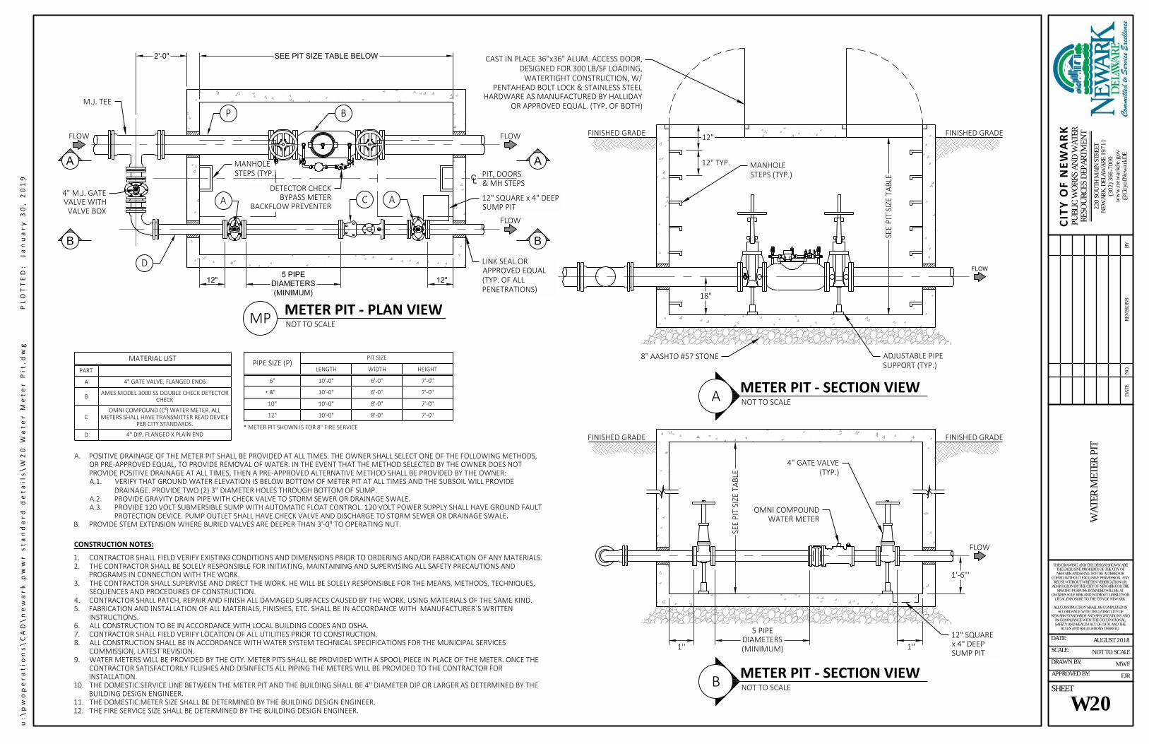
SEE PIT SIZE TABLE BELOW2'-0"
B
12" 12"
A A
18"
4" M.J. GATEVALVE WITHVALVE BOX
P
1'' 1''
5 PIPEDIAMETERS(MINIMUM)
MATERIAL LISTPART
A 4" GATE VALVE, FLANGED ENDS
B AMES MODEL 3000 SS DOUBLE CHECK DETECTORCHECK
COMNI COMPOUND (C2) WATER METER. ALL
METERS SHALL HAVE TRANSMITTER READ DEVICEPER CITY STANDARDS.
D 4" DIP, FLANGED X PLAIN END
PIPE SIZE (P) PIT SIZELENGTH WIDTH HEIGHT
6" 10'-0" 6'-0" 7'-0"8" 10'-0" 6'-0" 7'-0"10" 10'-0" 8'-0" 7'-0"12" 10'-0" 8'-0" 7'-0"
FINISHED GRADE FINISHED GRADE
FINISHED GRADE FINISHED GRADE
MANHOLESTEPS (TYP.)
1'-6"'
12"
12" TYP.
8" AASHTO #57 STONE
OMNI COMPOUNDWATER METER
4" GATE VALVE(TYP.)
D
C
M.J. TEE
A. POSITIVE DRAINAGE OF THE METER PIT SHALL BE PROVIDED AT ALL TIMES. THE OWNER SHALL SELECT ONE OF THE FOLLOWING METHODS,OR PRE-APPROVED EQUAL, TO PROVIDE REMOVAL OF WATER. IN THE EVENT THAT THE METHOD SELECTED BY THE OWNER DOES NOTPROVIDE POSITIVE DRAINAGE AT ALL TIMES, THEN A PRE-APPROVED ALTERNATIVE METHOD SHALL BE PROVIDED BY THE OWNER:A.1. VERIFY THAT GROUND WATER ELEVATION IS BELOW BOTTOM OF METER PIT AT ALL TIMES AND THE SUBSOIL WILL PROVIDE
DRAINAGE. PROVIDE TWO (2) 3" DIAMETER HOLES THROUGH BOTTOM OF SUMP.A.2. PROVIDE GRAVITY DRAIN PIPE WITH CHECK VALVE TO STORM SEWER OR DRAINAGE SWALE.A.3. PROVIDE 120 VOLT SUBMERSIBLE SUMP WITH AUTOMATIC FLOAT CONTROL. 120 VOLT POWER SUPPLY SHALL HAVE GROUND FAULT
PROTECTION DEVICE. PUMP OUTLET SHALL HAVE CHECK VALVE AND DISCHARGE TO STORM SEWER OR DRAINAGE SWALE.B. PROVIDE STEM EXTENSION WHERE BURIED VALVES ARE DEEPER THAN 3'-0" TO OPERATING NUT.
CONSTRUCTION NOTES:1. CONTRACTOR SHALL FIELD VERIFY EXISTING CONDITIONS AND DIMENSIONS PRIOR TO ORDERING AND/OR FABRICATION OF ANY MATERIALS.2. THE CONTRACTOR SHALL BE SOLELY RESPONSIBLE FOR INITIATING, MAINTAINING AND SUPERVISING ALL SAFETY PRECAUTIONS AND
PROGRAMS IN CONNECTION WITH THE WORK.3. THE CONTRACTOR SHALL SUPERVISE AND DIRECT THE WORK. HE WILL BE SOLELY RESPONSIBLE FOR THE MEANS, METHODS, TECHNIQUES,
SEQUENCES AND PROCEDURES OF CONSTRUCTION.4. CONTRACTOR SHALL PATCH, REPAIR AND FINISH ALL DAMAGED SURFACES CAUSED BY THE WORK, USING MATERIALS OF THE SAME KIND.5. FABRICATION AND INSTALLATION OF ALL MATERIALS, FINISHES, ETC. SHALL BE IN ACCORDANCE WITH MANUFACTURER`S WRITTEN
INSTRUCTIONS.6. ALL CONSTRUCTION TO BE IN ACCORDANCE WITH LOCAL BUILDING CODES AND OSHA.7. CONTRACTOR SHALL FIELD VERIFY LOCATION OF ALL UTILITIES PRIOR TO CONSTRUCTION.8. ALL CONSTRUCTION SHALL BE IN ACCORDANCE WITH WATER SYSTEM TECHNICAL SPECIFICATIONS FOR THE MUNICIPAL SERVICES
COMMISSION, LATEST REVISION.9. WATER METERS WILL BE PROVIDED BY THE CITY. METER PITS SHALL BE PROVIDED WITH A SPOOL PIECE IN PLACE OF THE METER. ONCE THE
CONTRACTOR SATISFACTORILY FLUSHES AND DISINFECTS ALL PIPING THE METERS WILL BE PROVIDED TO THE CONTRACTOR FORINSTALLATION.
10. THE DOMESTIC SERVICE LINE BETWEEN THE METER PIT AND THE BUILDING SHALL BE 4" DIAMETER DIP OR LARGER AS DETERMINED BY THEBUILDING DESIGN ENGINEER.
11. THE DOMESTIC METER SIZE SHALL BE DETERMINED BY THE BUILDING DESIGN ENGINEER.12. THE FIRE SERVICE SIZE SHALL BE DETERMINED BY THE BUILDING DESIGN ENGINEER.
CAST IN PLACE 36"x36" ALUM. ACCESS DOOR,DESIGNED FOR 300 LB/SF LOADING,WATERTIGHT CONSTRUCTION, W/
PENTAHEAD BOLT LOCK & STAINLESS STEELHARDWARE AS MANUFACTURED BY HALLIDAY
OR APPROVED EQUAL. (TYP. OF BOTH)
LINK SEAL ORAPPROVED EQUAL(TYP. OF ALLPENETRATIONS)
DETECTOR CHECKBYPASS METER
BACKFLOW PREVENTER12" SQUARE x 4" DEEPSUMP PIT
PIT, DOORS& MH STEPSC
L
SEE
PIT
SIZE
TAB
LE
SEE
PIT
SIZE
TAB
LE
ADJUSTABLE PIPESUPPORT (TYP.)
MANHOLESTEPS (TYP.)
METER PIT - PLAN VIEWNOT TO SCALEMP
5 PIPE
DIAMETERS
(MINIMUM)
METER PIT - SECTION VIEWNOT TO SCALEA
METER PIT - SECTION VIEWNOT TO SCALEB
B
A
B
A
FLOW
FLOW
FLOW
FLOW
FLOW
*
* METER PIT SHOWN IS FOR 8" FIRE SERVICE
12" SQUAREx 4" DEEPSUMP PIT
u:\p
wop
erat
ions
\CAD
\new
ark
pww
r sta
ndar
d de
tails
\W20
Wat
er M
eter
Pit.
dwg
PL
OTT
ED:
Janu
ary
30, 2
019
W20
220
SOU
TH M
AIN
STR
EET
NEW
ARK,
DEL
AWAR
E 19
711
(302
) 366
-700
0w
ww
.new
arkd
e.go
v@
City
ofN
ewar
kDE
CITY
OF
NEW
ARK
PUBL
IC W
ORK
S AN
D W
ATER
RESO
URC
ES D
EPAR
TMEN
TW
ATER
MET
ER P
IT
NOT TO SCALE
MWF
EJR
AUGUST 2018
THIS DRAWING AND THE DESIGN SHOWN ARETHE EXCLUSIVE PROPERTY OF THE CITY OFNEWARK AND SHALL NOT BE ALTERED OR
COPIED WITHOUT EXCLUSIVE PERMISSION. ANYREUSE WITHOUT WRITTEN VERIFICATION OR
ADAPTATION BY THE CITY OF NEWARK FOR THESPECIFIC PURPOSE INTENDED WILL BE AT
OWNERS SOLE RISK AND WITHOUT LIABILITY ORLEGAL EXPOSURE TO THE CITY OF NEWARK.
ALL CONSTRUCTION SHALL BE COMPLETED INACCORDANCE WITH THE LATEST CITY OF
NEWARK STANDARDS AND SPECIFICATIONS ANDIN COMPLIANCE WITH THE OCCUPATIONALSAFETY AND HEALTH ACT OF 1970 AND THE
RULES AND REGULATIONS THERETO.
DATE:
SCALE:
DRAWN BY:
APPROVED BY:
SHEET
BYRE
VISI
ON
SN
O.
DATE

2211 10
12
45
3
1
14
6
16
19
13
15
9
23
7
1821
20
8
17
2
Item No.123456789
1011121314151617181920212223
DescriptionUpper Half of BodyBottom Half of BodyBonnet BodyGateGate RubberIsolation GateIsolation Gate RubberStem (Feed Screw)Isolation Gate StemWrench NutSet CollarStem NutIsolation Gate Stem NutGasketChip Flushing PortEM Cutting PortSacrificial Anode Bolts/ NutsO-RingsBonnet BoltsPacking GlandPacking Gland BoltsBolt for Wrench NutBonnet O-Ring
MaterialDUCTILE IRONDUCTILE IRONDUCTILE IRONDUCTILE IRONEPDMDUCTILE IRONEPDMSTAINLESS STEELSTAINLESS STEELDUCTILE IRONBRASSBRONZEBRONZEEPDM
DUCTILE IRON WITH ZINC ANODESBUNA-NSTAINLESS STEELDUCTILE IRONSTAINLESS STEELSTAINLESS STEELEPDM
Part NumberSGU-0XX-001SGU-0XX-002SGU-0XX-005SGU-0XX-003SGU-0XX-004SGU-0XX-014
--SGU-0XX-006SGU-0XX-015SGU-0XX-011SGU-0XX-008SGU-0XX-010SGU-0XX-016SGU-0XX-007
----------
SGU-0XX-009------
*XX is Valve Size
SIZE
4” (118mm)
6” (170mm)
8” (222mm)
10” (274mm)
12” (326mm)
HEIGHT
18” (480mm)
21” (533mm)
24” (635mm)
27” (686mm)
29” (737mm)
LENGTH
17 34" (451mm)
L
H
17 34" (451mm)
17 34" (451mm)
19 34" (502mm)
19 34" (502mm)
4” - 12” EZ VALVE DIMENSIONS
LISTED NSF-61 CompliantADVANCED VALVE TECHNOLOGIES
RATED at 250 PSI
EZ VALVEtm
MEETS AWWA C-509-09
u:\p
wop
erat
ions
\CAD
\new
ark
pww
r sta
ndar
d de
tails
\W21
Sta
ndar
d In
sert
ion
Valv
e De
tail.
dwg
PL
OTT
ED:
Janu
ary
30, 2
019
220 SOUTH MAIN STREETNEWARK, DELAWARE 19711
(302) 366-7000www.newarkde.gov@CityofNewarkDE
CITY OF NEWARKPUBLIC WORKS AND WATERRESOURCES DEPARTMENT STANDARD INSERTION VALVE
DETAIL
THIS DRAWING AND THE DESIGN SHOWN ARETHE EXCLUSIVE PROPERTY OF THE CITY OFNEWARK AND SHALL NOT BE ALTERED OR
COPIED WITHOUT EXCLUSIVE PERMISSION.ANY REUSE WITHOUT WRITTEN VERIFICATION
OR ADAPTATION BY THE CITY OF NEWARKFOR THE SPECIFIC PURPOSE INTENDED WILL
BE AT OWNERS SOLE RISK AND WITHOUTLIABILITY OR LEGAL EXPOSURE TO THE CITY
OF NEWARK.
ALL CONSTRUCTION SHALL BE COMPLETED INACCORDANCE WITH THE LATEST CITY OF
NEWARK STANDARDS AND SPECIFICATIONSAND IN COMPLIANCE WITH THE
OCCUPATIONAL SAFETY AND HEALTH ACT OF1970 AND THE RULES AND REGULATIONS
THERETO.
NOT TO SCALE
MWF
EJR
AUGUST 2018DATE:
SCALE:
DRAWN BY:
APPROVED BY:
SHEET:
W21

4” - 12” EZ VALVE DIMENSIONS
LISTED NSF-61 Compliant
Item No.123456789
101112131415161717a1819
DescriptionBottom Half of BodyUpper Half of BodyBonnet BodyGateGate RubberIsolation GateIsolation Gate RubberStem (Feed Screw)Isolation Gate StemWrench NutSet CollarStem NutIsolation Gate Stem NutGasketChip Flushing PortEM Cutting PortBolts/ NutsSacrificial AnodesO-RingsBonnet Bolts
MaterialDUCTILE IRONDUCTILE IRONDUCTILE IRONDUCTILE IRONEPDMDUCTILE IRONEPDMSTAINLESS STEELSTAINLESS STEELDUCTILE IRONBRASSBRONZEBRONZEEPDM
DUCTILE IRONZINCEPDMSTAINLESS STEEL
ADVANCED VALVE TECHNOLOGIES
RATED at 250 PSI
4 Inch
6 Inch
8 Inch
10 Inch
12 Inch
EZ VALVE
B1A1
5.75
7
8.25
9.5
10.75
A2
9.75
9.75
9.75
9.75
9.75
B2
4.25
5.5
6.5
7.5
8.5
31.5
39.75
35.75
43.75
46.75
tm
MEETS AWWA C-509-01
C
28.25
36.5
32.5
40.5
43.5
A1
B1 B2
C
A2
u:\p
wop
erat
ions
\CAD
\new
ark
pww
r sta
ndar
d de
tails
\W22
Sha
llow
Mai
n In
sert
ion
Valv
e De
tail.
dwg
PL
OTT
ED:
Janu
ary
30, 2
019
220 SOUTH MAIN STREETNEWARK, DELAWARE 19711
(302) 366-7000www.newarkde.gov@CityofNewarkDE
CITY OF NEWARKPUBLIC WORKS AND WATERRESOURCES DEPARTMENT SHALLOW MAIN INSERTION
VALVE DETAIL
THIS DRAWING AND THE DESIGN SHOWN ARETHE EXCLUSIVE PROPERTY OF THE CITY OFNEWARK AND SHALL NOT BE ALTERED OR
COPIED WITHOUT EXCLUSIVE PERMISSION.ANY REUSE WITHOUT WRITTEN VERIFICATION
OR ADAPTATION BY THE CITY OF NEWARKFOR THE SPECIFIC PURPOSE INTENDED WILL
BE AT OWNERS SOLE RISK AND WITHOUTLIABILITY OR LEGAL EXPOSURE TO THE CITY
OF NEWARK.
ALL CONSTRUCTION SHALL BE COMPLETED INACCORDANCE WITH THE LATEST CITY OF
NEWARK STANDARDS AND SPECIFICATIONSAND IN COMPLIANCE WITH THE
OCCUPATIONAL SAFETY AND HEALTH ACT OF1970 AND THE RULES AND REGULATIONS
THERETO.
NOT TO SCALE
MWF
EJR
AUGUST 2018DATE:
SCALE:
DRAWN BY:
APPROVED BY:
SHEET:
W22

CR-6 PLACED LOOSELYAND COMPACTED1 IN
8" (MAX.) LIFTS
AASHTO NO. 10 "STONE DUST"OR SELECT BORROWCOMPACTED1 IN 8" (MAX.) LIFTS
SERVICE LATERAL /SANITARY MAIN
NOTES:1. COMPACTION TO BE ACHIEVED USING MECHANICAL TAMPER OF VIBRATORY COMPACTOR.2. FILTER FABRIC SHALL BE MIRAFI 140N OR APPROVED EQUAL.3. FOR PAVED AREAS, THE PAVEMENT SECTION REQUIRED IS DETERMINED BY THE TYPE OF ROAD AND WHETHER THE TRENCH IS LONGITUDINAL
OR PERPENDICULAR TO THE ROAD. CONTRACTOR TO VERIFY EXISTING PAVEMENT CROSS SECTION.4. FOR UNPAVED AREAS, VEGETATION SHALL BE RESTORED TO EXISTING CONDITIONS UNLESS OTHERWISE DIRECTED.
NO. 57 STONE BEDDING
6" TOPSOIL ANDSTABILIZED VEGETATION
PAVED UNPAVED
6"
6"
6"
NO. 57 STONE BEDDING
INITIAL BACKFILL BEFORE COMPACTION("STONE DUST" OR SELECT BORROW)
INITIAL BACKFILL BEFORECOMPACTION (CR-6)
PAVEMENT SECTION AS REQUIRED
PIPE O.D. +2'-0" MIN.
TYPICAL CROSS SECTION
1'-0"MIN.
1'-0"MIN.
PIPEO.D.
FILTER FABRIC2
u:\p
wop
erat
ions
\CAD
\new
ark
pww
r sta
ndar
d de
tails
\SS
Sani
tary
Sew
er T
renc
h De
tail.
dwg
PL
OTT
ED:
Janu
ary
30, 2
019
220 SOUTH MAIN STREETNEWARK, DELAWARE 19711
(302) 366-7000www.newarkde.gov@CityofNewarkDE
CITY OF NEWARKPUBLIC WORKS AND WATERRESOURCES DEPARTMENT SANITARY SEWER TRENCH
DETAIL
THIS DRAWING AND THE DESIGN SHOWN ARETHE EXCLUSIVE PROPERTY OF THE CITY OFNEWARK AND SHALL NOT BE ALTERED OR
COPIED WITHOUT EXCLUSIVE PERMISSION.ANY REUSE WITHOUT WRITTEN VERIFICATION
OR ADAPTATION BY THE CITY OF NEWARKFOR THE SPECIFIC PURPOSE INTENDED WILL
BE AT OWNERS SOLE RISK AND WITHOUTLIABILITY OR LEGAL EXPOSURE TO THE CITY
OF NEWARK.
ALL CONSTRUCTION SHALL BE COMPLETED INACCORDANCE WITH THE LATEST CITY OF
NEWARK STANDARDS AND SPECIFICATIONSAND IN COMPLIANCE WITH THE
OCCUPATIONAL SAFETY AND HEALTH ACT OF1970 AND THE RULES AND REGULATIONS
THERETO.
NOT TO SCALE
MWF
EJR
JANUARY 2019DATE:
SCALE:
DRAWN BY:
APPROVED BY:
SHEET:
SS1

THREADED PVCSCREW CAP
6" WYE OR TEE/WYE
PIPE
PIPE
1/8"
BEN
D
BRANCH
10" 10"
6"
4"
VARIES
3 12" HOT MIX
CONCRETEPAVEMENT
3500 A/ECONCRETE
Ø 15 58"
Ø 7 12"
1116"
DETAILFRAME & COVER
CASTINGEJ 1574ZPT APT ASSEMBLY ORAPPROVED EQUAL WITH THELETTER "S", "SANITARY", OR"SEWER" INSCRIBED ON THE LID
CLEANOUT/MONUMENTFRAME AND LID
FLOW
Ø 8 78"
Ø 9"
(2) OPEN PICKHOLES
(4) 1" DIA CORED HOLESAN A 13 12" DIA B.C.
(2) 38" - 16 PSOC SS CAPSCREWS ON 7" DIA B.C.
u:\p
wop
erat
ions
\CAD
\new
ark
pww
r sta
ndar
d de
tails
\SS2
Typ
ical
Cle
anou
t (Pa
ved)
.dw
g
PLO
TTED
: Ja
nuar
y 30
, 201
9
220 SOUTH MAIN STREETNEWARK, DELAWARE 19711
(302) 366-7000www.newarkde.gov@CityofNewarkDE
CITY OF NEWARKPUBLIC WORKS AND WATERRESOURCES DEPARTMENT
TYPICAL CLEANOUT (PAVED)
THIS DRAWING AND THE DESIGN SHOWN ARETHE EXCLUSIVE PROPERTY OF THE CITY OFNEWARK AND SHALL NOT BE ALTERED OR
COPIED WITHOUT EXCLUSIVE PERMISSION.ANY REUSE WITHOUT WRITTEN VERIFICATION
OR ADAPTATION BY THE CITY OF NEWARKFOR THE SPECIFIC PURPOSE INTENDED WILL
BE AT OWNERS SOLE RISK AND WITHOUTLIABILITY OR LEGAL EXPOSURE TO THE CITY
OF NEWARK.
ALL CONSTRUCTION SHALL BE COMPLETED INACCORDANCE WITH THE LATEST CITY OF
NEWARK STANDARDS AND SPECIFICATIONSAND IN COMPLIANCE WITH THE
OCCUPATIONAL SAFETY AND HEALTH ACT OF1970 AND THE RULES AND REGULATIONS
THERETO.
NOT TO SCALE
MWF
EJR
NOVEMBER 2018DATE:
SCALE:
DRAWN BY:
APPROVED BY:
SHEET:
SS2

6" WYE OR TEE/WYE
PIPE
PIPE
1/8"
BEN
D
BRANCH
BRASS LID FLUSHWITH PAVEMENT
GENCO OR APPROVEDEQUAL CAST IRON TOPVC BELL SCREW CAP
FINISHED GRADE
FLOW
BRASS SCREW CAP - PLAN VIEW
4" OR 6" BRASS SCREW PLUG - SECTION VIEW DETAIL
5"
PVC BELL JOINTRUBBER O-RING
COUNTER SUNKBRASS SCREW CAPON FRAME
5.915" I.D.6.275" O.D.
u:\p
wop
erat
ions
\CAD
\new
ark
pww
r sta
ndar
d de
tails
\SS3
Typ
ical
Cle
anou
t (Si
dew
alk)
.dw
g
PLO
TTED
: Ja
nuar
y 30
, 201
9
220 SOUTH MAIN STREETNEWARK, DELAWARE 19711
(302) 366-7000www.newarkde.gov@CityofNewarkDE
CITY OF NEWARKPUBLIC WORKS AND WATERRESOURCES DEPARTMENT TYPICAL CLEANOUT
(SIDEWALK)
THIS DRAWING AND THE DESIGN SHOWN ARETHE EXCLUSIVE PROPERTY OF THE CITY OFNEWARK AND SHALL NOT BE ALTERED OR
COPIED WITHOUT EXCLUSIVE PERMISSION.ANY REUSE WITHOUT WRITTEN VERIFICATION
OR ADAPTATION BY THE CITY OF NEWARKFOR THE SPECIFIC PURPOSE INTENDED WILL
BE AT OWNERS SOLE RISK AND WITHOUTLIABILITY OR LEGAL EXPOSURE TO THE CITY
OF NEWARK.
ALL CONSTRUCTION SHALL BE COMPLETED INACCORDANCE WITH THE LATEST CITY OF
NEWARK STANDARDS AND SPECIFICATIONSAND IN COMPLIANCE WITH THE
OCCUPATIONAL SAFETY AND HEALTH ACT OF1970 AND THE RULES AND REGULATIONS
THERETO.
NOT TO SCALE
MWF
EJR
AUGUST 2018DATE:
SCALE:
DRAWN BY:
APPROVED BY:
SHEET:
SS3

THREADED PVCSCREW CAP
6" WYE OR TEE/WYE
PIPE
PIPE
1/8"
BEN
D
BRANCH
COMPACTED SELECTBACKFILL MATERIAL
FINISHED GRADE
TOP OF CAP TO BE FLUSHOR 1" BELOW GRADEUNLESS OTHERWISEAPPROVED BY THE CITY
FLOW
u:\p
wop
erat
ions
\CAD
\new
ark
pww
r sta
ndar
d de
tails
\SS4
Typ
ical
Cle
anou
t (Gr
ass)
.dw
g
PLO
TTED
: Ja
nuar
y 30
, 201
9
220 SOUTH MAIN STREETNEWARK, DELAWARE 19711
(302) 366-7000www.newarkde.gov@CityofNewarkDE
CITY OF NEWARKPUBLIC WORKS AND WATERRESOURCES DEPARTMENT
TYPICAL CLEANOUT (GRASS)
THIS DRAWING AND THE DESIGN SHOWN ARETHE EXCLUSIVE PROPERTY OF THE CITY OFNEWARK AND SHALL NOT BE ALTERED OR
COPIED WITHOUT EXCLUSIVE PERMISSION.ANY REUSE WITHOUT WRITTEN VERIFICATION
OR ADAPTATION BY THE CITY OF NEWARKFOR THE SPECIFIC PURPOSE INTENDED WILL
BE AT OWNERS SOLE RISK AND WITHOUTLIABILITY OR LEGAL EXPOSURE TO THE CITY
OF NEWARK.
ALL CONSTRUCTION SHALL BE COMPLETED INACCORDANCE WITH THE LATEST CITY OF
NEWARK STANDARDS AND SPECIFICATIONSAND IN COMPLIANCE WITH THE
OCCUPATIONAL SAFETY AND HEALTH ACT OF1970 AND THE RULES AND REGULATIONS
THERETO.
NOT TO SCALE
MWF
EJR
AUGUST 2018DATE:
SCALE:
DRAWN BY:
APPROVED BY:
SHEET:
SS4

THREADED PVC SCREW CAP(SEE NOTE 1)
6" WYE OR TEE/WYE
PIPE
PIPE
BRANCH
COMPACTED SELECTBACKFILL MATERIAL
FINISHED GRADE
TOP OF CAP TO BE FLUSHOR 1" BELOW GRADEUNLESS OTHERWISEAPPROVED BY THE CITY(SEE NOTE 1)
6" WYE OR TEE/WYE
PIPE
PIPE
11.25°
BEND
BRANCH
12"MAX.
11.25°
BEND
NOTES:1. IF CLEANOUT IS LOCATED IN A PAVED ROAD OR DRIVEWAY, REFER TO "TYPICAL LATERAL CLEANOUT IN PAVED AREAS" DETAIL FOR
MONUMENT FRAME LID AND SCREW TYPE CAP.2. IF CLEANOUT IS LOCATED IN A CONCRETE SIDEWALK OR DRIVEWAY, REFER TO "TYPICAL CLEANOUT IN CONCRETE SIDEWALK OR DRIVEWAY"
DETAIL FOR BRASS LID AND CAST IRON SCREW CAP.
u:\p
wop
erat
ions
\CAD
\new
ark
pww
r sta
ndar
d de
tails
\SS1
8 Do
uble
Cle
an O
ut D
etai
l.dw
g
PLO
TTED
: Ja
nuar
y 30
, 201
9
220 SOUTH MAIN STREETNEWARK, DELAWARE 19711
(302) 366-7000www.newarkde.gov@CityofNewarkDE
CITY OF NEWARKPUBLIC WORKS AND WATERRESOURCES DEPARTMENT
DOUBLE CLEANOUT DETAIL
THIS DRAWING AND THE DESIGN SHOWN ARETHE EXCLUSIVE PROPERTY OF THE CITY OFNEWARK AND SHALL NOT BE ALTERED OR
COPIED WITHOUT EXCLUSIVE PERMISSION.ANY REUSE WITHOUT WRITTEN VERIFICATION
OR ADAPTATION BY THE CITY OF NEWARKFOR THE SPECIFIC PURPOSE INTENDED WILL
BE AT OWNERS SOLE RISK AND WITHOUTLIABILITY OR LEGAL EXPOSURE TO THE CITY
OF NEWARK.
ALL CONSTRUCTION SHALL BE COMPLETED INACCORDANCE WITH THE LATEST CITY OF
NEWARK STANDARDS AND SPECIFICATIONSAND IN COMPLIANCE WITH THE
OCCUPATIONAL SAFETY AND HEALTH ACT OF1970 AND THE RULES AND REGULATIONS
THERETO.
NOT TO SCALE
MWF
EJR
JANUARY 2019DATE:
SCALE:
DRAWN BY:
APPROVED BY:
SHEET:
SS5

6 1516"
24 18"
26 18"
1 12"
PLAN
34"
58"28 12"
35 78"
SECTION
1"
NEENAH FOUNDRYR-1642 FRAME & TYPE B LIDSKETCH NF42795(OR APPROVED EQUAL)
12" RAD.
27 58"
3 12"
MADE IN THE U.S.A.
HEAT NUMBER
ASTM A-48
CLASS 35B
(4) 1" DIA. ANCHOR BOLTHOLES ON A 33" DIA. B.C.
ANCHOR HOLE DETAIL
1"
26"
1"
SELF SEAL DETAIL
MACH. GROOVE IN LIDSEAT FOR 1 4" DIA.POLYISOPRENE GASKET(40 DUROMETER)
34"
38"
316"
14"
14"
CONCEALED PICKHOLEPER NF-22642
1" 12"
1"
1 1 4"
1 7 8"
58"
14"
FULL RADIUS
33" DIA. B.C.
TYPE B RECESSEDPOCKET
(1) 12" DIA. VENT HOLE
(4) CONCEALED PICKHOLES PER NF-22642
2" RAISED LETTERINGFLUSH W/ TOPSURFACE (TYP.)
u:\p
wop
erat
ions
\CAD
\new
ark
pww
r sta
ndar
d de
tails
\SS6
Sta
ndar
d M
anho
le F
ram
e an
d Co
ver.d
wg
PL
OTT
ED:
Janu
ary
30, 2
019
220 SOUTH MAIN STREETNEWARK, DELAWARE 19711
(302) 366-7000www.newarkde.gov@CityofNewarkDE
CITY OF NEWARKPUBLIC WORKS AND WATERRESOURCES DEPARTMENT STANDARD MANHOLE FRAME
AND COVER
THIS DRAWING AND THE DESIGN SHOWN ARETHE EXCLUSIVE PROPERTY OF THE CITY OFNEWARK AND SHALL NOT BE ALTERED OR
COPIED WITHOUT EXCLUSIVE PERMISSION.ANY REUSE WITHOUT WRITTEN VERIFICATION
OR ADAPTATION BY THE CITY OF NEWARKFOR THE SPECIFIC PURPOSE INTENDED WILL
BE AT OWNERS SOLE RISK AND WITHOUTLIABILITY OR LEGAL EXPOSURE TO THE CITY
OF NEWARK.
ALL CONSTRUCTION SHALL BE COMPLETED INACCORDANCE WITH THE LATEST CITY OF
NEWARK STANDARDS AND SPECIFICATIONSAND IN COMPLIANCE WITH THE
OCCUPATIONAL SAFETY AND HEALTH ACT OF1970 AND THE RULES AND REGULATIONS
THERETO.
NOT TO SCALE
MWF
EJR
AUGUST 2018DATE:
SCALE:
DRAWN BY:
APPROVED BY:
SHEET:
SS6

N
EW A
R
K
SA
N
I TA R Y S
E
WE
R
EJ ERGO ASSEMBLY00104174L03(OR APPROVED EQUAL)
MADE INTHE U.S.A.
ASTM A-48CLASS 35B
LOCKING CAM
PLAN
MULTI-TOOLPICKBAR
1 12"
(4) 2" X 1"SLOTTED HOLES
31 14"
FRAME SECTION
COVER SECTION
COVER SECTION
FRAME SECTION
CAM LOCK VIEW
HINGE POSITIONS
HINGE & GASKET VIEW
SAFETYCATCHAT 90°
REMOVALAT 120°
T-GASKET(INSTALLEDDURINGASSEMBLY)
CAST GASKET GROOVEFOR T-GASKET
HINGE
NOTE: MANHOLE ASSEMBLY SHALL BE INSTALLED AT A45° ANGLE TO EXISTING AND PROPOSED MAINS
Ø 28 516"
Ø 24"
7"
Ø 26 14"
1 516"
26"3 38"
90°120°
1 916"
Ø 35 78"
u:\p
wop
erat
ions
\CAD
\new
ark
pww
r sta
ndar
d de
tails
\SS7
Loc
king
Man
hole
Ass
embl
y.dw
g
PLO
TTED
: Ja
nuar
y 30
, 201
9
220 SOUTH MAIN STREETNEWARK, DELAWARE 19711
(302) 366-7000www.newarkde.gov@CityofNewarkDE
CITY OF NEWARKPUBLIC WORKS AND WATERRESOURCES DEPARTMENT
LOCKING MANHOLE ASSEMBLY
THIS DRAWING AND THE DESIGN SHOWN ARETHE EXCLUSIVE PROPERTY OF THE CITY OFNEWARK AND SHALL NOT BE ALTERED OR
COPIED WITHOUT EXCLUSIVE PERMISSION.ANY REUSE WITHOUT WRITTEN VERIFICATION
OR ADAPTATION BY THE CITY OF NEWARKFOR THE SPECIFIC PURPOSE INTENDED WILL
BE AT OWNERS SOLE RISK AND WITHOUTLIABILITY OR LEGAL EXPOSURE TO THE CITY
OF NEWARK.
ALL CONSTRUCTION SHALL BE COMPLETED INACCORDANCE WITH THE LATEST CITY OF
NEWARK STANDARDS AND SPECIFICATIONSAND IN COMPLIANCE WITH THE
OCCUPATIONAL SAFETY AND HEALTH ACT OF1970 AND THE RULES AND REGULATIONS
THERETO.
NOT TO SCALE
MWF
EJR
AUGUST 2018DATE:
SCALE:
DRAWN BY:
APPROVED BY:
SHEET:
SS7

REMOVE HOT MIX AND CONCRETECOLLAR FROM AROUND MANHOLEWHEN ADJUSTING TO GRADE
PLACE NEW FRAME AND COVEREVEN WITH EXITING GRADE.RE-COLLAR AND PLACE HOT MIXPATCH.
12"
16"
(4) SLOTS FOR3
4" BOLTS @ 90°
2"
WATERTIGHT FRAME AND COVERFURNISHED BY THE CITY WHERE NONE
EXIST (ON PUBLIC MANHOLES ONLY)
PLACE ADJUSTMENT RISERSAS REQUIRED
NOTES:1. DESIGN MEETS REQUIREMENTS OF A.S.T.M. STANDARD C-478.2. APPROXIMATE WEIGHT OF ONE REINFORCED CONCRETE RISER:
24"Ø - 140 LBS.30"Ø - 165 LBS.
REINFORCEDCONCRETE RISER
6 GAUGE WIREA = 0.029 SQ. IN.
8"
2" MIN
RUBBERADJUSTMENT RISER
RING MAY BETAPERED OR FLAT
8"
12" TO 3" MAX
NOTES:1. USE GNR INFRA-RISER RUBBER GRADE RINGS AS DISTRIBUTED
BY EAST JORDAN IRON WORKS, INC. EAST JORDAN, MICHIGANOR APPROVED EQUAL.
2. SEAL EACH JOINT BETWEEN FRAME, RUBBER GRADE RING ANDPRECAST GRADE RINGS USING SEALANT CONFORMING TO ASTMC920 AND SUITABLE FOR USE WITH MASONRY, RUBBER ANDMETAL MATERIALS. APPLY IN CONTINUOUS 1/2 INCH BEADS.
u:\p
wop
erat
ions
\CAD
\new
ark
pww
r sta
ndar
d de
tails
\SS8
Man
hole
Adj
ustm
ent a
nd C
oncr
ete
Colla
r.dw
g
PLO
TTED
: Ja
nuar
y 30
, 201
9
220 SOUTH MAIN STREETNEWARK, DELAWARE 19711
(302) 366-7000www.newarkde.gov@CityofNewarkDE
CITY OF NEWARKPUBLIC WORKS AND WATERRESOURCES DEPARTMENT MANHOLE ADJUSTMENT AND
CONCRETE COLLAR
THIS DRAWING AND THE DESIGN SHOWN ARETHE EXCLUSIVE PROPERTY OF THE CITY OFNEWARK AND SHALL NOT BE ALTERED OR
COPIED WITHOUT EXCLUSIVE PERMISSION.ANY REUSE WITHOUT WRITTEN VERIFICATION
OR ADAPTATION BY THE CITY OF NEWARKFOR THE SPECIFIC PURPOSE INTENDED WILL
BE AT OWNERS SOLE RISK AND WITHOUTLIABILITY OR LEGAL EXPOSURE TO THE CITY
OF NEWARK.
ALL CONSTRUCTION SHALL BE COMPLETED INACCORDANCE WITH THE LATEST CITY OF
NEWARK STANDARDS AND SPECIFICATIONSAND IN COMPLIANCE WITH THE
OCCUPATIONAL SAFETY AND HEALTH ACT OF1970 AND THE RULES AND REGULATIONS
THERETO.
NOT TO SCALE
MWF
EJR
DECEMBER 2018DATE:
SCALE:
DRAWN BY:
APPROVED BY:
SHEET:
SS8

2'-0" 8"8"VA
RIES
VARI
ESVA
RIES
8"CITY OF NEWARK STANDARDCAST IRON FRAME & COVERBY CONTRACTOR ADJUST TOGRADE AS REQUIRED
O-RING JOINTO-RING JOINT CONFORMS TOA.S.T.M. SPECIFICATIONS C361AND C443, LATEST REVISION.
MANHOLE DESIGN SPECIFICATIONSCONFORM TO "PRECAST REINFORCEDCONCRETE MANHOLE SPECIFICATIONSA.S.T.M. DESIGNATION C478", LATESTREVISION.
LIFT-PIN HOLES IN ALLPIECES FOR HANDLING
CONCRETE COMPRESSIVESTRENGTH 4,000 PSI
PIPE OPENINGS AS REQUIRED FORPIPE DIAMETERS 8" THROUGH 18"
AASHTO 57 STONE FOUNDATIONUNDER ALL MANHOLES - 12"DEEP, EXTEND 12" BEYONDMANHOLE EXTERIOR WALL.
CHANNELING/ALL WASTEWATER MANHOLES - PRE-CAST:BOTTOM OF MANHOLE TO BE CHANNELED AND BENCHED. MINIMUM CHANNEL DEPTH TO BE HALF THE DIAMETER OF INLET OR THROUGH PIPE.CHANNELS TO BE SMOOTH CONCRETE AND SEMI CIRCULAR IN SECTION. WHERE BRICK CHANNEL IS USED INVERT SHALL BE BRICK LAID ON EDGE.SUBJECT TO APPROVAL OF THE CITY OF NEWARK PUBLIC WORKS AND WATER RESOURCES DIRECTOR OR APPOINTED REPRESENTATIVE PRECASTCHANNELS MAY BE USED WITH THE UNDERSTANDING THAT IF ALIGNMENT OF FLOW CHANNEL IS MISALIGNED, CHANNEL WILL BE REMOVED ANDBRICK CHANNEL SHALL BE INSTALLED PER CITY OF NEWARK STANDARDS.
MANHOLE STEPS1'-3" O.C. (TYP.)
4'-0" 5"5"
8"-18"
SLOPE14" / FT
BENCH AND CHANNELPLACED ON SITE
CONCRETECOLLAR
6' M
INIM
UM
u:\p
wop
erat
ions
\CAD
\new
ark
pww
r sta
ndar
d de
tails
\SS9
48i
n M
anho
le D
etai
l.dw
g
PLO
TTED
: Ja
nuar
y 30
, 201
9
220 SOUTH MAIN STREETNEWARK, DELAWARE 19711
(302) 366-7000www.newarkde.gov@CityofNewarkDE
CITY OF NEWARKPUBLIC WORKS AND WATERRESOURCES DEPARTMENT
48IN MANHOLE DETAIL
THIS DRAWING AND THE DESIGN SHOWN ARETHE EXCLUSIVE PROPERTY OF THE CITY OFNEWARK AND SHALL NOT BE ALTERED OR
COPIED WITHOUT EXCLUSIVE PERMISSION.ANY REUSE WITHOUT WRITTEN VERIFICATION
OR ADAPTATION BY THE CITY OF NEWARKFOR THE SPECIFIC PURPOSE INTENDED WILL
BE AT OWNERS SOLE RISK AND WITHOUTLIABILITY OR LEGAL EXPOSURE TO THE CITY
OF NEWARK.
ALL CONSTRUCTION SHALL BE COMPLETED INACCORDANCE WITH THE LATEST CITY OF
NEWARK STANDARDS AND SPECIFICATIONSAND IN COMPLIANCE WITH THE
OCCUPATIONAL SAFETY AND HEALTH ACT OF1970 AND THE RULES AND REGULATIONS
THERETO.
NOT TO SCALE
MWF
EJR
NOVEMBER 2018DATE:
SCALE:
DRAWN BY:
APPROVED BY:
SHEET:
SS9

2'-0" 8"8"VA
RIES
VARI
ESVA
RIES
8"CITY OF NEWARK STANDARDCAST IRON FRAME & COVERBY CONTRACTOR ADJUST TOGRADE AS REQUIRED
O-RING JOINTO-RING JOINT CONFORMS TOA.S.T.M. SPECIFICATIONS C361AND C443, LATEST REVISION.
MANHOLE DESIGN SPECIFICATIONSCONFORM TO "PRECAST REINFORCEDCONCRETE MANHOLE SPECIFICATIONSA.S.T.M. DESIGNATION C478", LATESTREVISION.
LIFT-PIN HOLES IN ALLPIECES FOR HANDLING
CONCRETE COMPRESSIVESTRENGTH 4,000 PSI
PIPE OPENINGS AS REQUIRED FORPIPE DIAMETERS 21" THROUGH 27",AS WELL AS APPROVED INSIDE DROPSAND FORCE MAIN DISCHARGEMANHOLES.
AASHTO 57 STONE FOUNDATIONUNDER ALL MANHOLES - 12"DEEP, EXTEND 12" BEYONDMANHOLE EXTERIOR WALL.
CHANNELING/ALL WASTEWATER MANHOLES - PRE-CAST:BOTTOM OF MANHOLE TO BE CHANNELED AND BENCHED. MINIMUM CHANNEL DEPTH TO BE HALF THE DIAMETER OF INLET OR THROUGH PIPE.CHANNELS TO BE SMOOTH CONCRETE AND SEMI CIRCULAR IN SECTION. WHERE BRICK CHANNEL IS USED INVERT SHALL BE BRICK LAID ON EDGE.SUBJECT TO APPROVAL OF THE CITY OF NEWARK PUBLIC WORKS AND WATER RESOURCES DIRECTOR OR APPOINTED REPRESENTATIVE PRECASTCHANNELS MAY BE USED WITH THE UNDERSTANDING THAT IF ALIGNMENT OF FLOW CHANNEL IS MISALIGNED, CHANNEL WILL BE REMOVED ANDBRICK CHANNEL SHALL BE INSTALLED PER CITY OF NEWARK STANDARDS.
MANHOLE STEPS1'-3" O.C. (TYP.)
21"-27"
SLOPE14" / FT BENCH AND CHANNEL
PLACED ON SITE
CONCRETECOLLAR
6' M
INIM
UM
5'-0" 8"8"
u:\p
wop
erat
ions
\CAD
\new
ark
pww
r sta
ndar
d de
tails
\SS1
0 60
in M
anho
le D
etai
l.dw
g
PLO
TTED
: Ja
nuar
y 30
, 201
9
220 SOUTH MAIN STREETNEWARK, DELAWARE 19711
(302) 366-7000www.newarkde.gov@CityofNewarkDE
CITY OF NEWARKPUBLIC WORKS AND WATERRESOURCES DEPARTMENT
60IN MANHOLE DETAIL
THIS DRAWING AND THE DESIGN SHOWN ARETHE EXCLUSIVE PROPERTY OF THE CITY OFNEWARK AND SHALL NOT BE ALTERED OR
COPIED WITHOUT EXCLUSIVE PERMISSION.ANY REUSE WITHOUT WRITTEN VERIFICATION
OR ADAPTATION BY THE CITY OF NEWARKFOR THE SPECIFIC PURPOSE INTENDED WILL
BE AT OWNERS SOLE RISK AND WITHOUTLIABILITY OR LEGAL EXPOSURE TO THE CITY
OF NEWARK.
ALL CONSTRUCTION SHALL BE COMPLETED INACCORDANCE WITH THE LATEST CITY OF
NEWARK STANDARDS AND SPECIFICATIONSAND IN COMPLIANCE WITH THE
OCCUPATIONAL SAFETY AND HEALTH ACT OF1970 AND THE RULES AND REGULATIONS
THERETO.
NOT TO SCALE
MWF
EJR
DATE:
SCALE:
DRAWN BY:
APPROVED BY:
SHEET:
SS10
NOVEMBER 2018

MANHOLE STEPS1'-3" O.C. (TYP.)
CITY OF NEWARK STANDARDCAST IRON FRAME & COVERBY CONTRACTOR ADJUST TOGRADE AS REQUIRED
O-RING JOINTO-RING JOINT CONFORMS TOA.S.T.M. SPECIFICATIONS C361AND C443, LATEST REVISION.
MANHOLE DESIGN SPECIFICATIONSCONFORM TO "PRECAST REINFORCEDCONCRETE MANHOLE SPECIFICATIONSA.S.T.M. DESIGNATION C478", LATESTREVISION.
LIFT-PIN HOLES IN ALLPIECES FOR HANDLING
CONCRETE COMPRESSIVESTRENGTH 4,000 PSI
PIPE OPENINGS AS REQUIRED FORPIPE DIAMETERS GREATER THAN 27"OR WHEN DICTATED BY ANGLE OFPIPE PENETRATION.
AASHTO 57 STONE FOUNDATIONUNDER ALL MANHOLES - 12"DEEP, EXTEND 12" BEYONDMANHOLE EXTERIOR WALL.
MORTAR JOINTS SECTIONS SET INMORTAR GROUT AT INSTALLATION
CHANNELING/ALL WASTEWATERMANHOLES - PRE-CAST:BOTTOM OF MANHOLE TO BE CHANNELED ANDBENCHED. MINIMUM CHANNEL DEPTH TO BE HALFTHE DIAMETER OF INLET OR THROUGH PIPE.CHANNELS TO BE SMOOTH CONCRETE AND SEMICIRCULAR IN SECTION. WHERE BRICK CHANNEL ISUSED INVERT SHALL BE BRICK LAID ON EDGE.SUBJECT TO APPROVAL OF THE CITY OF NEWARKPUBLIC WORKS AND WATER RESOURCES DIRECTOROR APPOINTED REPRESENTATIVE PRECASTCHANNELS MAY BE USED WITH THEUNDERSTANDING THAT IF ALIGNMENT OF FLOWCHANNEL IS MISALIGNED, CHANNEL WILL BEREMOVED AND BRICK CHANNEL SHALL BEINSTALLED PER CITY OF NEWARK STANDARDS.
VARI
ESVA
RIES
3'-0
"6'
-0"
8"VA
RIES
2'-0" 8"8"
4'-0"
BENCH AND CHANNELPLACED ON SITE
SLOPE14" / FT
CONCRETECOLLAR
10' M
INIM
UM
VARIES (6'-0" MIN.) 8"8"
u:\p
wop
erat
ions
\CAD
\new
ark
pww
r sta
ndar
d de
tails
\SS1
1 72
in (a
nd L
arge
r) M
anho
le D
etai
l.dw
g
PLO
TTED
: Ja
nuar
y 30
, 201
9
220 SOUTH MAIN STREETNEWARK, DELAWARE 19711
(302) 366-7000www.newarkde.gov@CityofNewarkDE
CITY OF NEWARKPUBLIC WORKS AND WATERRESOURCES DEPARTMENT 72IN (AND LARGER) MANHOLE
DETAIL
THIS DRAWING AND THE DESIGN SHOWN ARETHE EXCLUSIVE PROPERTY OF THE CITY OFNEWARK AND SHALL NOT BE ALTERED OR
COPIED WITHOUT EXCLUSIVE PERMISSION.ANY REUSE WITHOUT WRITTEN VERIFICATION
OR ADAPTATION BY THE CITY OF NEWARKFOR THE SPECIFIC PURPOSE INTENDED WILL
BE AT OWNERS SOLE RISK AND WITHOUTLIABILITY OR LEGAL EXPOSURE TO THE CITY
OF NEWARK.
ALL CONSTRUCTION SHALL BE COMPLETED INACCORDANCE WITH THE LATEST CITY OF
NEWARK STANDARDS AND SPECIFICATIONSAND IN COMPLIANCE WITH THE
OCCUPATIONAL SAFETY AND HEALTH ACT OF1970 AND THE RULES AND REGULATIONS
THERETO.
NOT TO SCALE
MWF
EJR
DATE:
SCALE:
DRAWN BY:
APPROVED BY:
SHEET:
SS11
NOVEMBER 2018

NOTES:1. IF VERTICAL DISTANCE BETWEEN INVERT OF PROPOSED SANITARY SEWER INFLOW PIPE AND INVERT OF EXISTING CHANNEL IS 2' OR LESS,
RECONSTRUCT EXISTING CHANNEL/TABLE TO MEET INVERT OF PROPOSED INFLOW PIPE.2. THE MINIMUM DIAMETER OF AN INSIDE DROP MANHOLE SHALL BE 60". IF THE DIAMETER OF THE PROPOSED SANITARY SEWER INFLOW PIPE
IS GREATER THAN 8" OR MULTIPLE DROP CONNECTIONS ARE PROPOSED, MANHOLE SHALL BE 72" IN DIAMETER. WHEN CONNECTING TO ANEXISTING MANHOLE LESS THAN 60", THE MANHOLE SHALL BE REPLACED.
A-LOK OR APPROVED EQUALPIPE-TO-MANHOLE ADAPTOR
STAINLESS STEEL STRAPSUPPORTS & ANCHORS,SECURELY ANCHOREDTO MANHOLE WALLS
CHANNEL HEIGHT TO 1/2 PIPE DIA.SLOPE CHANNEL 1/4" PER FT.
DIAMETER OF RISER PIPE TO BEMINIMUM 2" LARGER THANDIAMETER OF INFLOW PIPE
DROP BOWL-RELINER B8DB OR
APPROVED EQUAL
MANHOLE
1/4 BEND
8" AASHTO#57 STONE
60" MIN. DIA. (SEE NOTE 2)
2" MIN.
SANITARY SEWER INFLOW PIPE
FLOW
FLOW
CROSS SECTION A-A
AA
MANHOLE
SEWER LINEFLOW CHANNELANGLED TOWARD FLOW
RISERPIPE
SANITARY SEWER INFLOW PIPE
u:\p
wop
erat
ions
\CAD
\new
ark
pww
r sta
ndar
d de
tails
\SS1
2 St
anda
rd S
anita
ry S
ewer
Inds
ide
Drop
Man
hole
.dw
g
PLO
TTED
: Ja
nuar
y 30
, 201
9
220 SOUTH MAIN STREETNEWARK, DELAWARE 19711
(302) 366-7000www.newarkde.gov@CityofNewarkDE
CITY OF NEWARKPUBLIC WORKS AND WATERRESOURCES DEPARTMENT STANDARD SANITARY SEWER
INDSIDE DROP MANHOLE
THIS DRAWING AND THE DESIGN SHOWN ARETHE EXCLUSIVE PROPERTY OF THE CITY OFNEWARK AND SHALL NOT BE ALTERED OR
COPIED WITHOUT EXCLUSIVE PERMISSION.ANY REUSE WITHOUT WRITTEN VERIFICATION
OR ADAPTATION BY THE CITY OF NEWARKFOR THE SPECIFIC PURPOSE INTENDED WILL
BE AT OWNERS SOLE RISK AND WITHOUTLIABILITY OR LEGAL EXPOSURE TO THE CITY
OF NEWARK.
ALL CONSTRUCTION SHALL BE COMPLETED INACCORDANCE WITH THE LATEST CITY OF
NEWARK STANDARDS AND SPECIFICATIONSAND IN COMPLIANCE WITH THE
OCCUPATIONAL SAFETY AND HEALTH ACT OF1970 AND THE RULES AND REGULATIONS
THERETO.
NOT TO SCALE
MWF
EJR
AUGUST 2018DATE:
SCALE:
DRAWN BY:
APPROVED BY:
SHEET:
SS12

FLO
W
FLO
W
FLO
WFL
OW
FLOW
FLO
W
FLO
W
FLOW FLOW
TERMINAL 1-WAY
3-WAY2-WAY
CONCRETE BENCH
CONCRETE FLOWCHANNEL
CONCRETE BENCH
CONCRETE FLOWCHANNEL
NOTE:1. CONCRETE SHALL BE 3500 PSI
u:\p
wop
erat
ions
\CAD
\new
ark
pww
r sta
ndar
d de
tails
\SS1
3 St
anda
rd C
onne
ctio
ns fo
r Man
hole
Flo
w C
hann
els.
dwg
PL
OTT
ED:
Janu
ary
30, 2
019
220 SOUTH MAIN STREETNEWARK, DELAWARE 19711
(302) 366-7000www.newarkde.gov@CityofNewarkDE
CITY OF NEWARKPUBLIC WORKS AND WATERRESOURCES DEPARTMENT STANDARD CONNECTIONS FOR
MANHOLE FLOW CHANNELS
THIS DRAWING AND THE DESIGN SHOWN ARETHE EXCLUSIVE PROPERTY OF THE CITY OFNEWARK AND SHALL NOT BE ALTERED OR
COPIED WITHOUT EXCLUSIVE PERMISSION.ANY REUSE WITHOUT WRITTEN VERIFICATION
OR ADAPTATION BY THE CITY OF NEWARKFOR THE SPECIFIC PURPOSE INTENDED WILL
BE AT OWNERS SOLE RISK AND WITHOUTLIABILITY OR LEGAL EXPOSURE TO THE CITY
OF NEWARK.
ALL CONSTRUCTION SHALL BE COMPLETED INACCORDANCE WITH THE LATEST CITY OF
NEWARK STANDARDS AND SPECIFICATIONSAND IN COMPLIANCE WITH THE
OCCUPATIONAL SAFETY AND HEALTH ACT OF1970 AND THE RULES AND REGULATIONS
THERETO.
NOT TO SCALE
MWF
EJR
AUGUST 2018DATE:
SCALE:
DRAWN BY:
APPROVED BY:
SHEET:
SS13

CL
A
A
1 18"
1'-0" MIN.
10 34"
9 14"
3 12"
1'-3" O.C.
5 34"
12" GRADE 60 STEEL
REINFORCEMENT BAR
COPOLYMER POLYPROPYLENE PLASTIC12" GRADE 60 STEEL
REINFORCEMENT BAR
SECTION A-A
TYPICAL WALL SECTION
NOTES:1. FIRST MANHOLE STEP SHALL BE A MINIMUM OF 12 INCHES AND
A MAXIMUM OF 24 INCHES FROM THE TOP/RIM ELEVATION.2. LAST MANHOLE STEP SHALL BE A MINIMUM OF 12 INCHES AND
A MAXIMUM OF 24 INCHES FROM THE BOTTOM OF THESTRUCTURE.
u:\p
wop
erat
ions
\CAD
\new
ark
pww
r sta
ndar
d de
tails
\SS1
4 St
anda
rd M
anho
le S
teps
.dw
g
PLO
TTED
: Ja
nuar
y 30
, 201
9
220 SOUTH MAIN STREETNEWARK, DELAWARE 19711
(302) 366-7000www.newarkde.gov@CityofNewarkDE
CITY OF NEWARKPUBLIC WORKS AND WATERRESOURCES DEPARTMENT
STANDARD MANHOLE STEPS
THIS DRAWING AND THE DESIGN SHOWN ARETHE EXCLUSIVE PROPERTY OF THE CITY OFNEWARK AND SHALL NOT BE ALTERED OR
COPIED WITHOUT EXCLUSIVE PERMISSION.ANY REUSE WITHOUT WRITTEN VERIFICATION
OR ADAPTATION BY THE CITY OF NEWARKFOR THE SPECIFIC PURPOSE INTENDED WILL
BE AT OWNERS SOLE RISK AND WITHOUTLIABILITY OR LEGAL EXPOSURE TO THE CITY
OF NEWARK.
ALL CONSTRUCTION SHALL BE COMPLETED INACCORDANCE WITH THE LATEST CITY OF
NEWARK STANDARDS AND SPECIFICATIONSAND IN COMPLIANCE WITH THE
OCCUPATIONAL SAFETY AND HEALTH ACT OF1970 AND THE RULES AND REGULATIONS
THERETO.
NOT TO SCALE
MWF
EJR
JANUARY 2019DATE:
SCALE:
DRAWN BY:
APPROVED BY:
SHEET:
SS14

12"2"
4' DIA. PRECAST CONCRETEMANHOLE BASE(4000 PSI MINIMUM)
PRECAST CONCRETEBENCH WITH CHANNELCHANNEL HEIGHT TO
3/4 OF PIPE HEIGHTINTEGRAL CAST
PVC PIPE GASKET
8" MIN.
6" MIN.
FINISH GRADETOPSOIL SEEDED AND MULCHED
4' MIN.
24" MIN.OPENING
7" MIN.
FRAME BOLTED TO TOP SECTIONWITH BUTYL RUBBER BETWEEN
FRAME AND TOP SECTION
WATER TIGHT BOLT DOWN MANHOLEFRAME AND COVER
3' MIN.
MANHOLE STEPS REQUIRED(NOT SHOWN) EXTERIOR WATERPROOF EPOXY
6" THICK AASHTO #57 AGGREGATEPLACED ON UNDISTURBED SUBGRADE
TYPICAL SECTION
PLAN
6' MAX.3' MIN.
NOTES:1. CITY OF NEWARK STANDARD CAST IRON FRAME & COVER BY CONTRACTOR ADJUST TO GRADE AS REQUIRED.2. MANHOLE DESIGN SPECIFICATIONS CONFORM TO "PRECAST REINFORCED CONCRETE MANHOLE SPECIFICATIONS A.S.T.M. DESIGNATION
C478", LATEST REVISION AND SHALL BE DESIGNED FOR HS-20 LIVE LOAD.
COVER SLAB NOTES:1. COVER SLAB SHALL BE PRECAST AND
DESIGNED FOR HS-20 LIVE LOAD.2. ALL BARS SHALL BE #5 SPACED AT 6"3. MINIMUM BAR COVER = 2"
u:\p
wop
erat
ions
\CAD
\new
ark
pww
r sta
ndar
d de
tails
\SS1
5 Sa
nita
ry S
ewer
Sha
llow
Man
hole
.dw
g
PLO
TTED
: Ja
nuar
y 30
, 201
9
220 SOUTH MAIN STREETNEWARK, DELAWARE 19711
(302) 366-7000www.newarkde.gov@CityofNewarkDE
CITY OF NEWARKPUBLIC WORKS AND WATERRESOURCES DEPARTMENT SANITARY SEWER SHALLOW
MANHOLE
THIS DRAWING AND THE DESIGN SHOWN ARETHE EXCLUSIVE PROPERTY OF THE CITY OFNEWARK AND SHALL NOT BE ALTERED OR
COPIED WITHOUT EXCLUSIVE PERMISSION.ANY REUSE WITHOUT WRITTEN VERIFICATION
OR ADAPTATION BY THE CITY OF NEWARKFOR THE SPECIFIC PURPOSE INTENDED WILL
BE AT OWNERS SOLE RISK AND WITHOUTLIABILITY OR LEGAL EXPOSURE TO THE CITY
OF NEWARK.
ALL CONSTRUCTION SHALL BE COMPLETED INACCORDANCE WITH THE LATEST CITY OF
NEWARK STANDARDS AND SPECIFICATIONSAND IN COMPLIANCE WITH THE
OCCUPATIONAL SAFETY AND HEALTH ACT OF1970 AND THE RULES AND REGULATIONS
THERETO.
NOT TO SCALE
MWF
EJR
DATE:
SCALE:
DRAWN BY:
APPROVED BY:
SHEET:
SS15
SEPTEMBER 2018

ENCASEMENT
NOTES:1. POUR CONCRETE AGAINST UNDISTURBED EARTH, REMOVE SHEETING BEFORE POURING CONCRETE OR LEAVE LOWER PORTION OF SHEETING
IN PLACE.2. CONTRACTOR IS RESPONSIBLE FOR PROPERLY SECURING PIPE BEFORE CONCRETE IS POURED.
3500 PSI CONCRETE
8" MAX.6" MIN.
8" MAX.6" MIN.
8" MAX.6" MIN.
LOW & HIGH CRADLE
8" MAX.6" MIN.8" MAX.
6" MIN.
3500 PSI CONCRETE
SELECTED BACKFILLWELL TAMPED IN
6" LAYERS
HIGH CRADLE - 3/4 O.D.LOW CRADLE - 1/4 O.D.
2' MIN.
u:\p
wop
erat
ions
\CAD
\new
ark
pww
r sta
ndar
d de
tails
\SS1
6 Co
ncre
te C
radl
e an
d En
case
men
t.dw
g
PLO
TTED
: Ja
nuar
y 30
, 201
9
220 SOUTH MAIN STREETNEWARK, DELAWARE 19711
(302) 366-7000www.newarkde.gov@CityofNewarkDE
CITY OF NEWARKPUBLIC WORKS AND WATERRESOURCES DEPARTMENT CONCRETE CRADLE AND
ENCASEMENT
THIS DRAWING AND THE DESIGN SHOWN ARETHE EXCLUSIVE PROPERTY OF THE CITY OFNEWARK AND SHALL NOT BE ALTERED OR
COPIED WITHOUT EXCLUSIVE PERMISSION.ANY REUSE WITHOUT WRITTEN VERIFICATION
OR ADAPTATION BY THE CITY OF NEWARKFOR THE SPECIFIC PURPOSE INTENDED WILL
BE AT OWNERS SOLE RISK AND WITHOUTLIABILITY OR LEGAL EXPOSURE TO THE CITY
OF NEWARK.
ALL CONSTRUCTION SHALL BE COMPLETED INACCORDANCE WITH THE LATEST CITY OF
NEWARK STANDARDS AND SPECIFICATIONSAND IN COMPLIANCE WITH THE
OCCUPATIONAL SAFETY AND HEALTH ACT OF1970 AND THE RULES AND REGULATIONS
THERETO.
NOT TO SCALE
MWF
EJR
AUGUST 2018DATE:
SCALE:
DRAWN BY:
APPROVED BY:
SHEET:
SS16

4" MUELLERVALVE
SCH-80END CAP
BINGHAM & TAYLOROR TYLER UNION6850 SERIESSCREW-TYPEVALVE BOX ORAPPROVED EQUAL
VALVEBOX
45° BENDSCH-80
18" PVCPIT
2" BALLVALVESCH-80
2" THREADEDSCREW CAP
4' TO 5'DEEP
4"
FORCE MAIN4" SDR-21
4"x2" WYESCH-80
2" S
DR-2
1
SEWERTAPE
1'
5'
3'
PLAN
TYPICAL SECTION
u:\p
wop
erat
ions
\CAD
\new
ark
pww
r sta
ndar
d de
tails
\SS1
7 Sa
nita
ry S
ewer
For
ce M
ain
Clea
nout
.dw
g
PLO
TTED
: Ja
nuar
y 30
, 201
9
220 SOUTH MAIN STREETNEWARK, DELAWARE 19711
(302) 366-7000www.newarkde.gov@CityofNewarkDE
CITY OF NEWARKPUBLIC WORKS AND WATERRESOURCES DEPARTMENT SANITARY SEWER FORCE MAIN
CLEANOUT
THIS DRAWING AND THE DESIGN SHOWN ARETHE EXCLUSIVE PROPERTY OF THE CITY OFNEWARK AND SHALL NOT BE ALTERED OR
COPIED WITHOUT EXCLUSIVE PERMISSION.ANY REUSE WITHOUT WRITTEN VERIFICATION
OR ADAPTATION BY THE CITY OF NEWARKFOR THE SPECIFIC PURPOSE INTENDED WILL
BE AT OWNERS SOLE RISK AND WITHOUTLIABILITY OR LEGAL EXPOSURE TO THE CITY
OF NEWARK.
ALL CONSTRUCTION SHALL BE COMPLETED INACCORDANCE WITH THE LATEST CITY OF
NEWARK STANDARDS AND SPECIFICATIONSAND IN COMPLIANCE WITH THE
OCCUPATIONAL SAFETY AND HEALTH ACT OF1970 AND THE RULES AND REGULATIONS
THERETO.
NOT TO SCALE
MWF
EJR
AUGUST 2018DATE:
SCALE:
DRAWN BY:
APPROVED BY:
SHEET:
SS17

NOTES:1. CONCRETE: 28 DAY F'C= 4500 PSI2. REBAR: ASTM A615 GRADE 603. MESH: ASTM A-185 GRADE 654. DESIGN: ACI318-83 BUILDING CODE
ASTM C-857 MINIMUM STRUCTURAL DESIGNLOADING FOR UNDERGROUND PRECASTCONCRETE UTILITY STRUCTURES
5. LOADS: H-20 TRUCK WHEEL W/30% IMPACT PER AASHTO6. FILL W/CLEAN WATER PRIOR TO START UP OF SYSTEM7. LICENSED PLUMBING CONTRACTOR TO SUPPLY & INSTALL ALL PIPING
NECESSARY FOR SANITARY TEES & CLEANOUTS. A DUAL CLEANOUTSHALL BE PROVIDED FOR CLEANING TOWARD & AWAY FROMINTERCEPTOR OUTLET (SEE DETAIL SS-GID-2).
8. INTERCEPTOR TO RECEIVE GRAY WATER ONLY. BLACK WATER SHALLBE CARRIED BY SEPARATE SEWER LATERAL.
9. SUM OF GREASE CAP & SOLIDS DEPTH ARE APPROXIMATELY EQUALTO, BUT NO GREATER THAN 1/2 OF THE DEPTH OF GRAY WATER.
10. SHALL HAVE STORAGE CAPACITY OF 1000 GALLONS MINIMUM.11. INLET & OUTLET TEES SHALL BE EITHER 4" OR 6" DIA. SDR-26 PVC OR
PRECAST CONCRETE. THEY SHALL NOT BE SMALLER IN DIAMETERTHAN THE DIAMETER OF THE INLET PIPE.
12. SEAL EACH RING JOINT BETWEEN FRAME AND ALL PRECAST GRADERINGS USING 20 OZ. OF 100% SILICONE SEALANT SUITABLE FOR USEWITH MASONRY AND METAL MATERIALS. APPLY IN CONTINUOUS1/2 INCH BEADS.
13. INTERCEPTOR SHALL BE INSTALLED BY A LICENSED PLUMBINGCONTRACTOR ONLY.
14. INTERCEPTOR SHALL BE INSPECTED BY CITY OF NEWARK, PRIOR TOBACKFILLING.
15. MANUFACTURER'S MODEL NUMBER SHALL BE CAST INTOINTERCEPTOR.
16. A COATING, RESISTANT TO POSSIBLE CHEMICAL REACTION, SHALL BEAPPLIED TO THE INTERIOR SURFACES OF THE INTERCEPTOR.
17. THE SANITARY DRAINAGE SYSTEM TO WHICH THE INTERCEPTOR ISCONNECTED SHALL BE VENTED TO A ROOF VENT, PER THEINTERNATIONAL PLUMBING CODE.
18. INTERCEPTOR SHALL BE INSTALLED ON LEVEL GRADE.19. PIPE CUTOUTS SHALL BE SEALED WITH INTEGRALLY CAST RUBBER
GASKET (A-LOK OR APPROVED EQUAL).20. TO MAINTAIN WATER TIGHT INTEGRITY, ANY JOINTS BELOW THE
THE SURFACE OF THE GRAY WATER SHALL BE SEALED WITH ACONTINUOUS APPLICATION OF BUTYL SEALANT.
21. EXCEPTIONS TO THIS DETAIL ARE SUBJECT TO REVIEW.
SECTION A-A
APPROXIMATELY EQUALTO BUT NO GREATERTHAN 3/4 OVERALLINTERIOR LENGTH
OVERALL INTERIOR LENGTH
CLEAR ACCESSOPENING (ABOVE)
PRECAST CONCRETE ORFIBERGLASS BAFFLE
2/3 OVERALL INTERIOR LENGTH 1/3 OVERALLINTERIOR LENGTH
INTEGRALLY CASTRUBBER GASKET (TYP.)SEE NOTE 20
B B
A AGREASE CAP
SELF SEALING MANHOLE FRAME AND COVER (TYP.)(COVER SHALL NOT READ CITY OF NEWARK)
ADD PRECAST RINGS TO ACHIEVE FINALGRADE (TYP.) MAXIMUM OF 12". USE
PRECAST RISER IF DISTANCE EXCEEDS 12".
SECTION B-B
PRECAST CONCRETE ORFIBERGLASS BAFFLE
2'-0"
2"
OPEN TO ENVIRONMENT &ACCESSIBLE FROM HATCH (TYP.)
12 OF GRAY
WATER DEPTH
DEPTH OFGRAY WATER
SOLIDS DEPTH APPROX. 14 OF GRAYWATER DEPTH, BUT NO LESS THAN 1'
APPROX. 14 OF GRAY WATERDEPTH, BUT NO LESS THAN 1' 4"
OUTLETINLET TO SANITARY SEWER
(SEE NOTES 7 & 14)
u:\p
wop
erat
ions
\CAD
\new
ark
pww
r sta
ndar
d de
tails
\SS1
8 Gr
ease
Inte
rcep
tor D
etai
l.dw
g
PLO
TTED
: Ja
nuar
y 30
, 201
9
220 SOUTH MAIN STREETNEWARK, DELAWARE 19711
(302) 366-7000www.newarkde.gov@CityofNewarkDE
CITY OF NEWARKPUBLIC WORKS AND WATERRESOURCES DEPARTMENT
GREASE INTERCEPTOR DETAIL
THIS DRAWING AND THE DESIGN SHOWN ARETHE EXCLUSIVE PROPERTY OF THE CITY OFNEWARK AND SHALL NOT BE ALTERED OR
COPIED WITHOUT EXCLUSIVE PERMISSION.ANY REUSE WITHOUT WRITTEN VERIFICATION
OR ADAPTATION BY THE CITY OF NEWARKFOR THE SPECIFIC PURPOSE INTENDED WILL
BE AT OWNERS SOLE RISK AND WITHOUTLIABILITY OR LEGAL EXPOSURE TO THE CITY
OF NEWARK.
ALL CONSTRUCTION SHALL BE COMPLETED INACCORDANCE WITH THE LATEST CITY OF
NEWARK STANDARDS AND SPECIFICATIONSAND IN COMPLIANCE WITH THE
OCCUPATIONAL SAFETY AND HEALTH ACT OF1970 AND THE RULES AND REGULATIONS
THERETO.
NOT TO SCALE
MWF
EJR
NOVEMBER 2018DATE:
SCALE:
DRAWN BY:
APPROVED BY:
SHEET:
SS18

City of Newark www.newarkde.gov Public Works and Water Resources Department
70 Last Revised February 2019
APPENDIX B

GENERAL PROVISIONS 1
These guidelines are for reference only. Final approval of pumping station design is solely based on City of Newark review and approval.
GENERAL PROVISIONS PART 1 GENERAL
1.1 SCOPE OF WORK
A) Furnish and provide all labor, equipment and materials to design, furnish
and install a complete and fully functional pump station as specified herein.
B) Requirements found in this division are common to all City of Newark pump stations. Refer to the subsequent divisions for specific requirements for suction lift and submersible pump stations, emergency generators and telemetry system.
C) If conditions are appropriate, City of Newark will require that a suction lift
pump station be designed for and furnished.
D) Sub-grade, pre-fabricated flooded suction pump stations are not acceptable to City of Newark.
E) A pump station that incorporates the use of grinder pump(s) is not
acceptable to City of Newark.
F) These guidelines include drawings for pump stations and force main. The drawings shall be used with these guidelines to interpret the City of Newark standard. The drawings are not to scale, and shall be used for information only.
G) Due to changing technology and practices, these guidelines are for
reference only. City of Newark reserves the right to update these guidelines without notification. All equipment supplied and labor performed is subject to individual review and approval by City of Newark.
1.2 SUBMITTALS
A) Submit completely scaled and dimensioned drawings in plan and cross
section as required to provide a complete description of the entire system. Drawings shall be certified for construction by a Professional Engineer and approved by City of Newark.
B) Drawings shall include the following at a minimum:
1) Site, elevation and plan views that completely describe the pump station 2) Force main from the pump station to discharge point in plan and elevation

GENERAL PROVISIONS 2
These guidelines are for reference only. Final approval of pumping station design is solely based on City of Newark review and approval.
3) Equipment layout with specific dimensions and locations 4) Location of electrical connections and characteristics 5) Wiring diagrams for all equipment 6) Wiring diagrams for motor and level controllers 7) Utility requirements (type, size and location(s)) 8) Supports and anchor bolt layout 9) Mounting requirements and clearances 10) Assembly views and materials of construction of all equipment 11) Diameter of shafting 12) Dimensions and rated horsepower of all motors 13) Gear and bearing ratings 14) Service factors and weights 15) Equipment sizing calculations
C) After the drawings are approved, the Contractor shall submit equipment
dimensions and construction, performance data including pump curves; equipment capacities, characteristics and limitations; materials of construction and finishes to City of Newark for review and approval. No equipment shall be installed prior to approval by City of Newark. City of Newark shall be the sole and final judge of the acceptability of materials and equipment.
D) Indicate installation requirements and special procedures as recommended
by the manufacturer. Provide equipment preparation and start-up procedures.
E) Submit copies of factory run pump performance tests for pump size and
type selected, prior to pump delivery.
F) Submit engineering calculations supporting equipment and material selected. Calculations for the pump station and force main shall be submitted as described herein.
1.3 ENGINEERING CALCULATIONS
A) Calculations must include detailed pump station plans that clearly depict the
proposed pump station, sanitary sewer, number of houses to be serviced by the pump station and force main up to the discharge point. Static head (pump off elevation to discharge point), lengths of pipe (force main and pump station) and approximate fittings must be clearly identified.
B) Both the average and peak hourly sewage flows must be determined.
Industry standards should be used in calculating the average sewage flows, which are determined from type of buildings or area that the pump station

GENERAL PROVISIONS 3
These guidelines are for reference only. Final approval of pumping station design is solely based on City of Newark review and approval.
will service. The peak flow shall be determined by multiplying the average flow by 4.
The peak flow shall be used to determine the size of the pumps.
C) The pump size and requirements shall be determined from a pipe friction loss analysis of the pump station piping and force main up to the discharge point. It is preferred that the Hazen-Williams method be used to calculate pipe friction loss. However, any standard engineering methods used to calculate pipe friction loss is acceptable. All formulas, constants and assumptions must be clearly explained in the calculation. If computer software is used, calculations must include all assumptions, conditions, and any other information that is necessary to review the analysis. Calculations that show results only are not acceptable.
The following formula and constants shall be used if using the Hazen- Williams formula:
where,
hf – Pipe friction loss head (feet of water) C – Hazen-Williams flow coefficient Q –Flow rate (GPM) D – Internal pipe diameter (inches) EL – Equivalent Length of pipe and fittings (feet)
hf – Pipe friction loss head (feet of water) C – Hazen-Williams flow coefficient Q –Flow rate (GPM) D – Internal pipe diameter (inches) EL – Equivalent Length of pipe and fittings (feet)
For ductile iron piping and fittings, C shall be 110. For PVC and HDPE piping, C shall equal 140 for new installations.
Losses shall include suction and discharge losses for piping and fittings, plus static head.
D) The system curve shall be determined and transposed to a
manufacturer’s pump performance curve. The assumed operating point shall be indicated, along with the appropriate motor size, impeller size, and motor speed, as applicable.

GENERAL PROVISIONS 4
These guidelines are for reference only. Final approval of pumping station design is solely based on City of Newark review and approval.
E) The motor size shall be chosen such that the motor is non-overloading
over the entire impeller curve.
F) Pump stations shall be designed with sufficient wet well volume to limit pump starts to no more than six (6) starts in one hour (or the peak cycle time must be greater than 10 minutes). The following formula shall be used to determine the cycle time of the pump:
where,
V – Volume between the pump on and off elevations, (gallons) Qpump – Flow rate at the assumed operating point
G) Submit NPSH and re-prime calculations for suction lift stations.
H) The emergency generator shall be capable of handling all miscellaneous loads (heater(s), blowers, lights, etc.), one pump running and one pump starting. It is recommended that the manufacturer or their representative determine the size of the generator and the appropriate appurtenances. See the section on emergency generators for more details.
I) Ventilation for the building and wet well shall be sized to meet or
exceed NFPA code 820.
1.4 OPERATION AND MAINTENANCE DATA
A) The Contractor shall be responsible for supplying written instructions that are sufficiently comprehensive to enable the operator to operate and maintain the pump station and all equipment supplied. The instructions shall assume that the operator is familiar with pumps, motors, piping, and valves, but that he has not previously operated and/or maintained the exact equipment supplied.
B) Submit five (5) copies of manuals prepared by the manufacturer / supplier
or the Contractor within four weeks following the receipt of accepted shop drawings to City of Newark for review and approval. The submission and approval of each set of manuals will be considered to be an integral part of furnishing and installing the respective equipment or system. The Contractor will be informed if the submitted manuals are incomplete or

GENERAL PROVISIONS 5
These guidelines are for reference only. Final approval of pumping station design is solely based on City of Newark review and approval.
require revision. The Contractor shall supply the information necessary for completion in a timely manner.
C) The manuals shall include, but not limited to the following elements for
all equipment supplied:
1) Erection or installation instructions.
2) Operating / performance data for specified equipment.
3) Start-up procedures.
4) Recommended and alternative (including back-up emergency) procedures.
5) Troubleshooting guide.
6) Schedule and type of preventative maintenance required. 7) Replacement parts list and schedule of recommended spare parts to
be stocked, complete with part number, inventory quantity and ordering information.
8) Detailed maintenance procedures.
9) Schedule of lubrication requirements.
10) Corrected and approved control and wiring diagrams.
11) Data sheet listing pertinent equipment or system information.
12) Addresses and telephone numbers of the nearest sales and
service representatives.
13) Manufacturer’s warranty on all equipment supplied.
B) Operation and maintenance instructions that are limited to a collection of component manufacturer literature without overall pump station instructions are not acceptable.
C) Operation and maintenance instructions shall be specific to the equipment
supplied in accordance with these guidelines. Instruction manuals applicable to many different configurations and pump stations, and which require the operator to selectively read portions of the instructions are not acceptable.

GENERAL PROVISIONS 6
These guidelines are for reference only. Final approval of pumping station design is solely based on City of Newark review and approval.
1.5 QUALITY ASSURANCE
A) Design and construct the pumps in accordance with standards of the Hydraulic Institute. The efficiency of the pumps, when operating under conditions of the specified capacities and heads shall be as near peak efficiency as practicable.
B) Obtain pumping equipment, motors, drives, pump controls and
appurtenance from a pump supplier whose responsibility is to ensure that the pumping equipment is properly coordinated and operated in accordance with these guidelines.
C) The Contractor shall acquire the services of the equipment
manufacturer's representative for testing, instruction, and correction of deficiencies.
D) The pumps, motors, and controls shall be given an operational test in
accordance with the standards of the Hydraulic Institute. Recordings of the test shall substantiate the correct performance of the equipment at the design head, capacity, suction lift (if applicable), speed and horsepower as herein specified.
E) After the installation is complete, a qualified factory representative shall place the pump station in operation, conduct a complete function check, and make all necessary adjustments for regular service.
F) The Contractor is responsible to honor the manufacturer’s warranty on all
equipment for one (1) year from the date of acceptance by City of Newark. The Contractor shall provide a copy of all warranty documentation from the equipment manufacturer at the time of acceptance.
G) The Contractor shall provide a warranty against any defect or malfunction
due to workmanship in the equipment and accessories for a minimum period of one (1) year from the date of final acceptance by City of Newark, unless otherwise stated in the individual pump station sections. In the event a component fails or is proven defective during the guarantee period, the Contractor will provide a replacement part and installation without cost to City of Newark.
H) A written manufacturer’s warranty shall be supplied for all
individual components, and included in the Operation and Maintenance manual.
I) The Contractor is responsible for storing, delivering and handling all
material, equipment and machinery in accordance with the manufacturer’s

GENERAL PROVISIONS 7
These guidelines are for reference only. Final approval of pumping station design is solely based on City of Newark review and approval.
recommendations.
1.7 SCHEDULING AND COORDINATION
A) The Contractor shall schedule and attend a pre-construction meeting with City of Newark Department of Special Services. Parties that shall attend the meeting shall include a representative from the site contractor, the pump station contractor and City of Newark Department of Special Services. No work shall be performed on the pumping station prior to this pre- construction meeting.
B) The Contractor is responsible to coordinate the delivery and installation of
all equipment and materials. This includes, but is not limited to, all work completed by sub-contractors, utilities, manufacturer’s representatives, City of Newark inspections and other involved parties.
C) All work shall be performed under the supervision of a City of Newark
Inspector. Any work performed while the Inspector is not present is subject to removal and reinstallation at the cost of the Contractor.
PART 2 MATERIALS
2.1 VALVES
A) Check Valves
1) Full port swing check valves shall have cast iron body with flanged ends
drilled to ANSI 125 pattern. Valves shall be fitted with an external lever, weights and/or spring. The bronze or stainless steel body ring shall be pinned into the valve port. The valve clapper shall be cast iron, replaceable resilient face, and shall swing completely clear of the waterway when the valve is fully open. The hinge pin shall be of 18-8 stainless steel construction and shall be utilized with bronze bushings and packing or O-ring seals. Valves shall be equipped with removable cover plate to permit entry for cleaning of the valve without removing the valve from the line. Valve rating shall be 175 psi water working pressure, 350 psi hydrostatic test pressure. Pump stations with pressure above 50 psi or excessive water hammer may need a slow closing check valve, pump control valve and/or a surge relief valve. See “Sanks” (Pump Design Handbook) Section 7 for control of hydraulic transients for guidance.
2) Check valves shall be Golden-Anderson, APCO Valve & Primer, Nibco or
approved equal.

GENERAL PROVISIONS 8
These guidelines are for reference only. Final approval of pumping station design is solely based on City of Newark review and approval.
B) Isolation Valves
1) The plug valve shall be of the non-lubricated, resilient faced, eccentric type. The valve body shall be semi-steel with flanged end connection drilled to ANSI 125-lbs standards. The valve shall be furnished with a drip-tight shutoff plug mounted in stainless steel bearings and shall have a resilient facing bonded to the sealing surface. The valve shall be operated with a single lever actuator providing lift, turn and re-seat action. The lever shall be equipped with a locking device to hold the plug in the desired position. Plug valves shall be DeZurick or approved equal.
2) The resilient seated gate valve shall be solid wedge, non-rising stem
with guided wedge for buried service. For indoor applications, OS&Y design is acceptable. The valve shall be designed to handle abrasive and solids without fouling the seats. The gate valve shall be rated for 175 psi operating pressure, minimum. The valve body, bonnet and gate shall be constructed from ductile iron; gate shall be rubber covered. Valves shall have flanged end connections drilled to ANSI 125-pound standards.
3) All isolation valves shall be equipped with a cast iron handwheel
for operation.
4) Buried valves shall include a valve box with stem extension and 2” square operator.
5) Gate valves shall be US Pipe Metroseal 250, or equal.
C) Sewage Air Release Valves
1) Air release valves shall be installed at high points on the force main,
and/or in the station, as directed by City of Newark. Air release valves shall be of full body design, unless otherwise approved by City of Newark.
2) The body and cover shall be of cast iron conforming to ASTM A126 class
B. All internal parts of the air release valve shall be of stainless steel.
3) The air release valve shall be float operated and shall employ a compound lever mechanism to enable the valve to automatically release accumulated air and gases from the pipe while the system is pressurized and operating. The linkage/lever mechanism shall be able to be removed from the valve without disassembly of the mechanism.

GENERAL PROVISIONS 9
These guidelines are for reference only. Final approval of pumping station design is solely based on City of Newark review and approval.
4) The air release valve shall close drip tight, incorporating an adjustable orifice button.
5) Valve shall be specified with manufacturer’s backflushing kit for
backwashing with clear water.
6) City of Newark may also require air/vacuum release valves as needed by the force main design.
7) Air (or air/vacuum) release valves shall be as manufactured by GA
Industries, APCO, ARI or City of Newark approved equal. 2.2 STATION PIPING
A) Discharge piping (and suction piping if applicable) shall be ductile iron pipe,
class 52. Ductile iron pipe shall conform to AWWA C150 and C151.
B) The exterior of the ductile iron pipe shall include an asphaltic coating. The interior of the pipe shall include a cement mortar lining.
C) Pipe 3” in diameter and larger shall be flanged, centrifugally cast.
D) Fittings 3” in diameter and larger shall be standard ANSI B16.1 with Class
125 flat faced and drilled flanges utilizing 304 stainless steel bolts.
E) Pipe 2” in diameter and smaller shall be ASTM A312, grade TP304, schedule 40 stainless steel.
F) Fittings 2” in diameter and smaller shall be threaded to ANSI B2.1 pipe thread and suitable thread sealant applied before assembly.
G) All hardware for pipe, fittings and valves shall be stainless steel.
H) Discharge lines shall include an eccentric plug valve or resilient seated
gate valve to permit either or both pumps to be isolated, and a check valve to prevent back flow.
I) All flanged connections shall include a gasket or non-asbestos composition
and minimum thickness of 1/8”. Gaskets shall be coated with thread lubricant prior to making up joints.
J) Drain pipe and vent lines shall be Schedule 80 PVC. Vent lines shall be gray.
K) Pipe hangers and supports shall be constructed of heavy-duty welded steel
brackets made of 304 stainless steel. U-bolts shall also be made of 304

GENERAL PROVISIONS 10
These guidelines are for reference only. Final approval of pumping station design is solely based on City of Newark review and approval.
stainless steel with double hex nuts and shall comply with Federal Specification WW-H-171E (type 24) and Manufacturer’s Standardization Society SP-69 (type 24). Brackets and U-bolts shall be manufactured by ITT Grinnel or approved equal.
L) A bypass connection shall be installed in the pump station discharge piping
so emergency bypass pumping may be performed. A buried gate valve shall be placed in the force main just downstream of the bypass. The bypass line shall include an isolation valve and a Bauer quick-connect fitting of suitable size.
M) Piping shall be ductile iron up to the bypass connection, or outside of the
pump station building footer. No bends shall be buried under the station floor. All buried pipe shall receive an outside bituminous seal coat.
N) Pipe couplings shall be Tyler solid long sleeve Model 5144-L. Retainer
glands shall be used on ductile iron pipe and plain glands shall be used on PVC pipe. Coupling length shall be twice its diameter.
O) Flanges shall be faced and a gasket finish applied that shall have concentric grooves. Bolt holes shall be in alignment within 2° between flanges.
P) Flanged to flexible connection devices may be required for each suction
and discharge connection to correct misalignment and alleviate stresses.
Q) Mechanical joint pipe is not acceptable in pump stations.
R) Wall and floor penetrations shall include galvanized pipe sleeves with interlocking pipe seals. Pipe seals shall be Thunderline or equal.
S) Pipe and valves shall be independently supported such that the weight of
the piping is not transmitted to either the valves or the pump casing. 2.3 FORCE MAIN
A) Force main piping may change to Polyvinyl Chloride (PVC) or High Density
Polyethylene (HDPE) after the bypass connection. The appropriate restrained mechanical joint adapter from ductile iron pipe shall be used. PVC piping and HDPE shall have a minimum pressure rating of 150 psi, or as directed by City of Newark.
B) Buried ductile iron pipe shall include an exterior asphaltic coating.
C) A restrained mechanical joint (suitable for the piping material) is required

GENERAL PROVISIONS 11
These guidelines are for reference only. Final approval of pumping station design is solely based on City of Newark review and approval.
for bends outside of the station and as directed by City of Newark. Restrained mechanical joints shall be as manufactured by EBAA Iron or approved equal.
D) PVC pipe shall conform to AWWA C900 and C905 and shall be suitable for
pressurized sewer. Joints shall be gasketed bell and spigot push-on. Gaskets shall comply with ASTM F477. Pipe shall be clearly marked with DR number and size.
E) HDPE pipe shall conform to AWWA C901/C906 and shall be suitable for
pressurized sewer. Joints shall be butt-fused. Pipe shall be clearly marked with SDR number and size.
F) The force main shall be sized and located to minimize friction losses, meet
the minimum allowable velocity of 2.5 feet per second and facilitate maintenance. If possible, the force main shall generally rise from the pump station to the discharge point, limiting high points. An air release valve shall be installed at all high points, or as directed by City of Newark.
G) Force main shall be a minimum of 4 inches in diameter, unless
otherwise approved by City of Newark.
H) The following force main appurtenances shall be included as specified or as directed by City of Newark. See the standard details for more information.
1) Air release valves at high points. 2) In-line cleanouts every 400 feet. 3) Terminal cleanouts at all bends greater than 30 degrees.
2.4 PUMP STATION SITE AND BUILDING
A) All pumps and controls shall be enclosed in a building as specified in the standard drawings. The building shall be sized such that each piece of equipment retains a minimum of 3 feet clearance between other equipment or walls, where practical.
B) Site shall include paving for adequate vehicle parking and vehicle access
from the main road. Paving shall be 2” hot mix, hot laid bituminous concrete Type C on 2” hot mix, hot laid bituminous concrete Type B on 8” graded aggregate base course, Type A. In general, the building should be surrounded by a minimum of 10 feet of paving on all sides.
C) Pump station exterior shall be brick or split-faced concrete block.

GENERAL PROVISIONS 12
These guidelines are for reference only. Final approval of pumping station design is solely based on City of Newark review and approval.
Colors should match colors used on the development homes.
D) Site shall include landscaping in accordance with City of Newark Unified Development Code (UDC). Landscaping includes but is not limited to shrubs, trees and other plants as required. All plants and shrubs should be non- deciduous, low maintenance, and appropriate for this region.
E) All material installed that is not specified herein shall be a high-quality,
industrial grade product. City of Newark has the right to not accept a product based on perceived quality or experience.
F) Ventilation
1) Ventilation for the pumping station shall be designed in accordance
with NFPA 820.
2) For suction lift pumping stations, air shall be supplied to the building via fan and exhausted via gravity in the building. Ventilation should be sized for 6 air changes per hour, and operate intermittently.
a) The wet well should include a minimum 4 inch inverted-J gravity air
vent, with stainless steel insect screen.
3) For submersible stations, air shall be supplied to the building via fan and exhausted via gravity in the building. Ventilation should be sized for 6 air changes per hour, and operate intermittently.
a) Wet well ventilation shall include both a supply and exhaust fan,
each sized for a minimum of 12 air changes per hour, with the exhaust fan size slightly larger. The fans shall be wired together such that if the exhaust fan is inoperable, the supply fan is also inoperable. Wet well ventilation shall operate continuously.
G) Heater
1) An industrial grade, explosion proof, space heater shall be provided in
the pump station. The heater shall be controlled by an adjustable thermostat,and be properly sized according to the overall building dimensions, with a minimum of 3,400 BTUs.
H) Storage cabinet
1) A heavy-duty steel storage cabinet shall be provided in the pump
station. The cabinet shall have two flush mounted doors with hasp and shall have minimum dimensions of 36”W x 34”H x 24”D without wheels.

GENERAL PROVISIONS 13
These guidelines are for reference only. Final approval of pumping station design is solely based on City of Newark review and approval.
The cabinet shall be as manufactured by Bruce Industrial Shop Cabinet, Model WG4961, or approved equal.
2.5 WET WELL
A) The wet well shall be sized in accordance with the calculations
described above.
B) The wet well shall be designed as specified in the standard drawings.
C) Wet well shall be ventilated as described above.
D) The wet well shall be supplied with manhole rungs or ladder that extends to the bottom of the wet well. Manhole rungs shall be ½” Grade 60 steel encased in polypropylene plastic. A ladder should be constructed of 3/8” x 3” aluminum risers, with 1” grooved rungs, secured a maximum of every 5 feet. Manhole rungs and ladder rungs shall be 12” on center, 12” wide, extend a minimum of 6” away from the wet well wall and shall include a “grab bar” at the top of the wet well to facilitate entrance.
E) Access Hatch
1) Provide an access hatch for required maintenance, installation and
removal of pumps. Access hatch shall meet the following requirements:
a) Hatch shall have a minimum opening of 30” x 36”, or as required for removal of submersible pumps with a straight pull up the guide rails.
b) Aluminum, single or double leaf, non-drainage, 300 lb/ft3 live load, stainless steel hardware, concealed hinges, integral safety grating, hold open arm, gasketed to provide air or weather tight barrier between wet well and pump room or outdoors. Submersible pump stations require a double leaf access hatch.
c) Hydraulic, pneumatic and / or cam action type assist to provide
easy opening and dampened closing of the door.
d) Access hatch shall be installed flush with the station floor or paving with no protruding parts to present a trip hazard.
e) If access hatch is located outdoors, hatch must include lock and provisions to handle water.
f) Access hatch as manufactured by Halliday Products, or

GENERAL PROVISIONS 14
These guidelines are for reference only. Final approval of pumping station design is solely based on City of Newark review and approval.
approved equal.
G) Door, Frame and Hardware
1) Doors shall be double leaf, each leaf being 3’ x 7’ nominal, thermally insulated polystyrene core. Doors shall be 1¾” thick, 16 gauge with 14 gauge top and bottom channels.
2) Door(s) shall have a galvanized exterior, primed and finished with
an industrial quality paint. The color shall be selected by City of Newark.
3) Frames and thresholds shall suit the grade and model of door. Frame
shall be 14 gauge (minimum) and provided with three (3) wall anchor jambs and one (1) anchor to floor. Anchors shall be 18 gage minimum.
4) Each door shall be installed with three (3) stainless steel hinges with a
satin finish. The door lockset shall also be stainless steel with satin finish. Lockset shall be keyed to the City of Newark standard. Lockset shall be as manufactured by Schlage.
H) Fencing
1) Fencing is necessary to prevent vandalism where outdoor equipment
is necessary (odor control system, telemetry tower, etc.). Fencing will be necessary as determined by City of Newark.
2) Fencing shall be galvanized mesh with green vinyl privacy slats. Fence
posts shall be galvanized and secured in a 12” diameter concrete footing that extends a minimum of 3 feet into the ground.
3) Fencing shall be located 12” inside the edge of paving, or as directed
by City of Newark. 2.6 PUMP CONTROLS
A) The following requirements cover the system for duplex pumping stations.
The system includes a liquid level control, control panel and all other components as required to complete the system. City of Newark may also require variable frequency drives (VFDs) and magnetic flow meters.
1) The pump manufacturer shall supply the pump control system to ensure
a complete system and total system responsibility. The pumps, motors andcontrol system shall be set up and tested as a unit at the pump manufacturer’s facility.

GENERAL PROVISIONS 15
These guidelines are for reference only. Final approval of pumping station design is solely based on City of Newark review and approval.
2) The motor control panel enclosure shall be constructed in conformance
with applicable section of NEMA Standards for Type 3R electrical enclosures. Enclosure shall be fabricated of steel having a minimum thickness of not less than 0.075 inch (14 gauge). All seams shall be continuously welded, and shall be free of burrs and voids. All surfaces shall be finished with baked-on enamel. There shall be no holes through the external walls of the enclosure either for mounting the enclosure or for mounting any components contained within the enclosure.
3) Enclosures shall be equipped with a hinged door held closed with
clamps that are quick and easy to operate. The door shall accommodate the mounting of switches and indicators.
4) Enclosures shall be furnished with a removable back panel, fabricated of
steel having a thickness of not less than 0.106 inch (12 gauge), which shall be secured to the enclosure with collar studs. Such panels shall be of adequate size to accommodate all basic components.
5) All control components shall be securely fastened to a removable back
panel with screws and lock washers. Switches, indicators and instruments shall be mounted through the control panel door. Self-tapping screws shall not be used to mount any components.
6) Each control assembly shall be furnished with main terminals and
ground lug for field connection of the electrical supply. The connections shall be designed to accept copper conductors of sufficient size to serve the loads. The main terminals shall be mounted to allow incoming wire bending space in accordance with the National Electric Code (NEC). A separate terminal strip shall be provided for 115 volt, single-phase control power via a central power transmitter and shall be segregated from the main terminals. Ten percent of the control terminals shall be furnished as spares.
7) Indicating lights shall be oil tight type and equipped with integral
step- down transformers for long lamp life. Lamps shall be light emitting diodes (LEDs) with a minimum life of 15,000 hours. LEDs shall be replaceable from the front without opening the control panel door and without the use of tools.
8) The manufacturer may use selector switches, pushbutton switches, or
any combination thereof to accomplish the switching tasks described herein. Switches shall be oil tight with contacts rated NEMA A-300 minimum.

GENERAL PROVISIONS 16
These guidelines are for reference only. Final approval of pumping station design is solely based on City of Newark review and approval.
9) Control logic may be accomplished using electro-mechanical relays or a programmable controller, as described herein:
a) Electro-mechanical relays and timers shall be equipped with 120 VAC
coils and contacts rated NEMA A-300 minimum. Timers shall be pneumatic or synchronous motor driven.
b) Programmable controls shall operate on 120 VAC power and be
equipped with 120 VAC inputs and hard contact outputs. Outputs shall have an inductive load rating equivalent to a size 4 contactor. The power supply to the programmable control shall include an active tracking filter protection system to minimize the effects of electrical noise. In addition, each motor starter or contactor shall be equipped with a surge suppressor.
c) Operator interface equipment shall be provided to permit field
adjustment of the programmable control timers and counters and shall be mounted on the control panel with other operator controls and displays.
d) The program logic shall be stored in battery backed random
access memory, as well as on a programmable read, read only memory module. The memory module shall be included to facilitate field repair or replacement of the programmable control hardware.
e) The Operation and Maintenance Manual shall be provided
with complete ladder logic program documentation including English names, rung comments, and coil/contact cross references.
f) The control shall be pre-programmed or wired to provide the
following routines:
(i) Pump alternation at lead stop. (ii) Excessive pump run time alternation (1-9999 minutes.) (iii) Jump to idle pump/drive on lead failure. (iv) Start/stop drives. (v) Pump start delays after power restoration (automatic.) (vi) Flashing alarm/steady acknowledge on all alarm pilot lights. (vii) Station trouble alarm (115 VAC and normally open dry contact.) (viii) High level alarms. (ix) Pump high temperature shutdown.
10) All motor branch components shall be of the highest industrial quality.

GENERAL PROVISIONS 17
These guidelines are for reference only. Final approval of pumping station design is solely based on City of Newark review and approval.
Operating coils or all AC control devices shall be rated for 120 volts and shall be suitable for use in a voltage range of 108 to 132 volts, 60-hertz.
B) Variable Frequency Drives (VFDs)
1) Due to frequency of changes in electronics and technology, and the
infrequency of their requirement, contact City of Newark for detailed specifications on VFDs. The following paragraphs include general requirements for VFDs.
2) The VFD shall be furnished, programmed and guaranteed by the
pump manufacturer to ensure proper system integration.
3) The VFD shall be a complete, stand alone system including control logic, operator interface, diagnostics and power.
4) The VFD shall be supplied with all auxiliary components required to
produce a complete, fully functional unit.
C) Magnetic Flow Meters
1) Due to frequency of changes in electronics and technology, and the infrequency of their requirement, contact City of Newark for detailed specifications on magnetic flow meters. The following includes general requirements for magnetic flow meters.
2) Magnetic flow meters shall consist of a submersible duty primary
instrument mounted in the discharge piping and a secondary transmitter and receiver mounted within the equipment mounting cabinet. Both components shall be the product of a single manufacturer. The flow meter shall be factory calibrated, and include an electronic data recording device.
2.7 LIQUID LEVEL CONTROL
A) General
1) The level control system shall start and stop the pump motors in response to change in the wet well level, as described herein. The level control system shall be capable of operating as either an air bubbler system or submersible transducer system. Floats are not acceptable for primary level indication.
2) The level control system shall utilize the alternator relay to select the

GENERAL PROVISIONS 18
These guidelines are for reference only. Final approval of pumping station design is solely based on City of Newark review and approval.
first pump, then the second pump to run as lead pump for a pumping cycle. Alternation shall occur at the end of a pumping cycle.
3) The level control system shall continuously monitor the wet well level,
permitting the operator to read the level at any time. Upon operator selection of automatic operation, the motor for one pump shall start when the liquid level in the wet well rises to the “lead pump start level”. When the liquid is lowered to the “lead pump stop level”, the pump will stop. These actions shall constitute one pumping cycle. Should the wet well level continue to rise, the second pump shall start when the liquid reaches the “lag pump start level” so that both pumps are operating. These levels shall be adjustable.
4) The level controller shall include integral components to perform all
pressure sensing, signal conditioning, EMI and RFI suppression, DC power supply and 120 volt outputs and comparators. Comparators shall be solid state and shall be integrated with other components.
5) The level controller shall be capable of operating on a supply voltage
of 108 volts to 132 volts AC, 60 Hertz, in an ambient temperature range of –10 °C (14 °F) through 55 °C (131 °F). Control range shall be 0 to 20 feet of water with an overall repeat accuracy of ±0.1 feet of water. Memory shall be retained using a non-volatile lithium battery back up.
6) The level controller shall incorporate a digital back lighted panel display
which, upon operator selection, shall indicate liquid level in the wet well and the preset start and stop level for both lead and lag pump. The display shall include alphanumeric characters calibrated to read out directly in feet of water, accurate to within one-tenth foot with a full-scale indication of not less than 12 feet.
7) Level adjustments shall be electronic comparator set points to control
the levels at which the lead and lag pumps start and stop.
8) Each of the level settings shall be adjustable, and accessible to the operator without opening the level controller or any cover panel. Controls shall be provided to permit the operator to read the selected levels on the display. Such adjustments shall not require hard wiring, the use of electronic test equipment, artificial level simulation or introduction of pressure to the system.
9) Each output relay shall be solid state. The “ON” state of each relay shall
be indicated by illumination of an LED. The output of each relay shall be individually fused providing overload and short circuit protection. Each
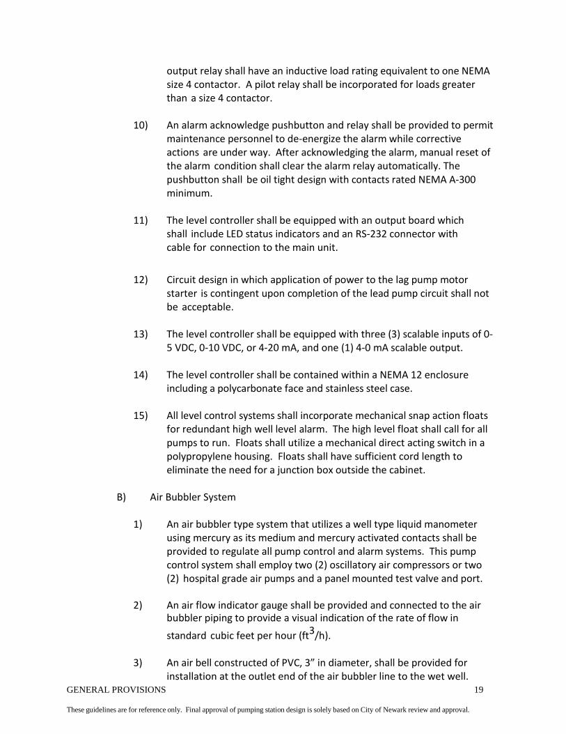
GENERAL PROVISIONS 19
These guidelines are for reference only. Final approval of pumping station design is solely based on City of Newark review and approval.
output relay shall have an inductive load rating equivalent to one NEMA size 4 contactor. A pilot relay shall be incorporated for loads greater than a size 4 contactor.
10) An alarm acknowledge pushbutton and relay shall be provided to permit
maintenance personnel to de-energize the alarm while corrective actions are under way. After acknowledging the alarm, manual reset of the alarm condition shall clear the alarm relay automatically. The pushbutton shall be oil tight design with contacts rated NEMA A-300 minimum.
11) The level controller shall be equipped with an output board which
shall include LED status indicators and an RS-232 connector with cable for connection to the main unit.
12) Circuit design in which application of power to the lag pump motor starter is contingent upon completion of the lead pump circuit shall not be acceptable.
13) The level controller shall be equipped with three (3) scalable inputs of 0-
5 VDC, 0-10 VDC, or 4-20 mA, and one (1) 4-0 mA scalable output.
14) The level controller shall be contained within a NEMA 12 enclosure including a polycarbonate face and stainless steel case.
15) All level control systems shall incorporate mechanical snap action floats
for redundant high well level alarm. The high level float shall call for all pumps to run. Floats shall utilize a mechanical direct acting switch in a polypropylene housing. Floats shall have sufficient cord length to eliminate the need for a junction box outside the cabinet.
B) Air Bubbler System
1) An air bubbler type system that utilizes a well type liquid manometer
using mercury as its medium and mercury activated contacts shall be provided to regulate all pump control and alarm systems. This pump control system shall employ two (2) oscillatory air compressors or two (2) hospital grade air pumps and a panel mounted test valve and port.
2) An air flow indicator gauge shall be provided and connected to the air
bubbler piping to provide a visual indication of the rate of flow in
standard cubic feet per hour (ft3/h).
3) An air bell constructed of PVC, 3” in diameter, shall be provided for installation at the outlet end of the air bubbler line to the wet well.

GENERAL PROVISIONS 20
These guidelines are for reference only. Final approval of pumping station design is solely based on City of Newark review and approval.
The bell shall have a 3/8 NPT tapped for connection of the bubbler line. Provide adapter to connect ½” PVC bubbler line.
4) The air bubbler line shall be ¼” polyethylene tubing and shall be looped
above grade to provide flood protection. The bubbler line shall exit through a ¾” pipe fitting in the wall. The bubbler line shall be carried in a ¾” steel pipe between the station and the wet well. The carrier pipe shall be sealed at both ends.
5) The air bubbler system shall be provided with a circuit to alternate
power to the air pumps should the air pressure drop below a preset value, measured by a pressure switch. A pilot light located in the control panel shall indicate an air pump failure. Dry alarm contacts wired to terminal blocks shall also be provided. Circuit shall be manually reset.
C) Submersible Transducer
1) The transducer shall be designed for installation in a wet well and shall
be manufactured completely of stainless steel, or equal non-corrosive material.
2) The transducer shall include a stainless steel diaphragm to further
protect the unit from the effects of the sewage.
3) Transducers shall be appropriately scaled for the wet well and shall provide a 4 – 20 mA output, 12 – 30 VDC input.
4) The unit shall have sufficient cord length to avoid the need for a
junction box in the wet well.
D) Both submersible transducers and air bubbler bells shall be contained within a stilling well. Stilling wells shall incorporate an 8” PVC pipe with 1” holes drilled throughout the pipe. The pipe shall be anchored to the wet well and shall span from the bottom of the wet well to above the high well level.
E) City of Newark reserves the right to require alternate level control
equipment on a case by case basis. Alternate level control equipment may include but not limited to ultrasonic or conductive level indicators.
2.8 ELECTRICAL CONTROL COMPONENTS
A) Electrical power to be furnished to the pump station shall be 3 phase, 4
wire; 480, 240 or 208 volts, maintained within ± 10% for all stations.

GENERAL PROVISIONS 21
These guidelines are for reference only. Final approval of pumping station design is solely based on City of Newark review and approval.
Control voltage shall not exceed 132 volts.
B) All electrical control components shall be mounted in one enclosure as specified herein.
C) Main Distribution Panel
1) The enclosure shall be constructed in conformance with applicable
sections of NEMA Standards for Type 3R enclosures. The enclosure shall be fabricated of steel having a minimum thickness of not less than 0.075 inch (14 gauge). All seams shall be continuously welded, and shall be free of burrs and voids. All surfaces shall be finished with baked-on white enamel. There shall be no holes through the external walls of the enclosure either for mounting the enclosure or for mounting any components contained within the enclosure.
D) Swing Panel
1) Enclosure shall be equipped with a removable inner swing panel, fabricated of steel having a thickness of not less than 0.063 inch (16 ga.), and mounted with a continuous steel hinge. Panel shall have a minimum horizontal swing of 90 degrees, and shall be held closed with straight slot screws. Panel shall completely cover all wiring and components on the back panel and shall accommodate the mounting of controls, switches, and indicators.
E) Back Panel
1) Enclosure shall be furnished with a removable back panel, fabricated of
steel having a thickness of not less than 0.106 inch (12 ga.), which shall be secured to the enclosure with collar studs. Such panel shall be of adequate size to accommodate all basic and optional components.
F) Door
1) Enclosure shall be equipped with a door mounted on a continuous
stainless steel hinge. Door shall be held closed with a three point latching mechanism provided with a keyed lock. Door shall have a horizontal swing of not less than 165 degrees.
G) Location of Controls and Instruments
1) All operating controls and instruments shall be securely mounted in such
a manner that any or all standard options offered by the pump station manufacturer may be added in the field without rearrangement of

GENERAL PROVISIONS 22
These guidelines are for reference only. Final approval of pumping station design is solely based on City of Newark review and approval.
existing controls and instruments. All controls and instruments shall be clearly labeled to indicate function.
2.9 MOTOR BRANCH COMPONENTS
A) All motor branch components shall be of the highest industrial quality. Operating coils of all AC control devices shall be rated for 120 volts and shall be suitable for use in a voltage range of 108 to 132 volts, 60 hertz. Components shall be securely fastened to a removable back panel with screws and lock-washers. The back panel shall be tapped to accept all mounting screws. Self-tapping screws shall not be used to mount any components.
B) Circuit Breaker and Operating Mechanism
1) A properly sized thermal-magnetic air circuit breaker shall be
furnished for each pump motor. The manufacturer shall seal all circuit breakers after calibration to prevent tampering.
C) Motor Starters
1) An open frame across the line, NEMA rated magnetic motor starter shall be furnished for each pumps motor. Starters of NEMA Size 1 and above shall be designed for addition of at least two front mounted auxiliary contacts. IEC rated starters and starters rated “0”, “00”, or fractional sizes are not acceptable. Power contacts shall be double-break and made of cadmium oxide silver. All motor starters shall be equipped to provide under voltage release and overload protection on all three phases. Motor starter contacts shall be easily replaceable without removing the motor starter from its mounted position.
2) Motors of 15 HP or larger shall incorporate solid state reduced voltage
magnetic starters. “Soft” starters shall be equipped with thermal overload protection, bypass contactors and under voltage release for the protection of the pump motors. Starters shall automatically reset. Motor starters shall be manufactured by Benshaw, Safetronics, Allen-Bradley, Cutler- Hammer or approved equal.
D) Overload Relays
1) Overlay relays shall be block-type, utilizing melting alloy type spindles,
and shall have visual trip indication with trip-free operation. Pressing of the overload reset lever shall not actuate the control contact until such time as the overload spindle has reset. Re-setting of the overload reset

GENERAL PROVISIONS 23
These guidelines are for reference only. Final approval of pumping station design is solely based on City of Newark review and approval.
lever will cause a snap-action control to reset, thus reestablishing a control circuit. Overload relays shall be manual reset only and not convertible to automatic reset. Trip setting shall be determined by heater element only and not by adjustable overload relays.
2.10 OTHER CONTROL COMPONENTS
A) Phase Monitor
1) Provide a phase monitor to monitor low voltage and high voltage, phase unbalance, phase loss and phase reversal. Monitor shall stop the motor. When phase is restored, reset shall be automatic. Provide set of dry contacts for telemetry.
B) Provide an elapsed time meter for each pump.
C) Provide a motor start counter for each pump.
D) Provide an ammeter for submersible pumping stations.
E) Switch Controls
1) Switches shall be furnished to accomplish the following
minimum functions:
a) Disconnect the control circuit. b) Select the mode of operation for each pump. c) Operate the level control system as described below. d) Override all controls except motor overload relays.
F) Wiring
1) General
a) The unit pump assembly as furnished by the manufacturer shall be
completely wired, except for the power feeder lines and final connections to alarm devices. All wiring, workmanship and schematic wiring diagrams shall be in compliance with applicable standards and specifications for industrial controls set forth by the NMTBA and NEC.The power and control wiring shall be directly installed from the pumps to the control panel (no junction box).
b) All user serviceable wiring shall be Type MTW or THW, 600 volts, and
shall be color-coded as follows:
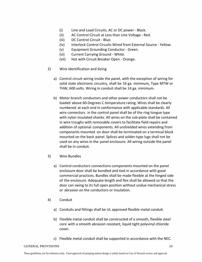
GENERAL PROVISIONS 24
These guidelines are for reference only. Final approval of pumping station design is solely based on City of Newark review and approval.
(i) Line and Load Circuits, AC or DC power - Black. (ii) AC Control Circuit at Less than Line Voltage - Red. (iii) DC Control Circuit - Blue. (iv) Interlock Control Circuits Wired from External Source - Yellow. (v) Equipment Grounding Conductor - Green. (vi) Current Carrying Ground - White. (vii) Hot with Circuit Breaker Open - Orange.
2) Wire Identification and Sizing
a) Control circuit wiring inside the panel, with the exception of wiring for
solid state electronic circuitry, shall be 16 ga. minimum, Type MTW or THW, 600 volts. Wiring in conduit shall be 14 ga. minimum.
b) Motor branch conductors and other power conductors shall not be
loaded above 60-Degrees C temperature rating. Wires shall be clearly numbered at each end in conformance with applicable standards. All wire connectors in the control panel shall be of the ring tongue type with nylon insulated shanks. All wires on the sub-plate shall be contained in wire troughs with removable covers to facilitate field repairs and addition of optional components. All unshielded wires extending from components mounted on door shall be terminated on a terminal block mounted on the back panel. Splices and solder-type lugs shall not be used on any wires in the panel enclosure. All wiring outside the panel shall be in conduit.
3) Wire Bundles
a) Control conductors connections components mounted on the panel
enclosure door shall be bundled and tied in accordance with good commercial practices. Bundles shall be made flexible at the hinged side of the enclosure. Adequate length and flex shall be allowed so that the door can swing to its full open position without undue mechanical stress or abrasion on the conductors or insulation.
4) Conduit
a) Conduits and fittings shall be UL approved flexible metal conduit.
b) Flexible metal conduit shall be constructed of a smooth, flexible steel
core with a smooth abrasion resistant, liquid tight polyvinyl chloride cover.
c) Flexible metal conduit shall be supported in accordance with the NEC.

GENERAL PROVISIONS 25
These guidelines are for reference only. Final approval of pumping station design is solely based on City of Newark review and approval.
C onduit shall be sized according to NEC. 2.11 ODOR CONTROL
A) City of Newark may require an odor control system to be installed with the
pump station. If an odor control system is required, the system shall be as designed and supplied by U.S. Filter’s Davis Products. Davis Products can be contacted at (800) 345-3982.
2.12 SPARE PARTS
A) The following spare parts shall be furnished with a suction lift pump station:
1) One spare parts kit consisting of the following: One (1) cover plate O-
ring, One (1) rotating assembly O-ring, One (1) complete mechanical seal assembly, and One (1) set of rotating assembly shims.
2) One rotating assembly, including an impeller, wear plate, and seal plate and 17-4PH stainless steel shaft.
3) One (1) spare impeller 4) Two (2) suction flange gaskets 5) One (1) fill cover gasket 6) Two (2) discharge flange gaskets 7) One (1) pump suction flap valve assembly 8) One (1) wear plate assembly 9) Two (2) air release valve springs 10) One (1) suction gauge (-34' to +34') 11) One (1) discharge gauge (0-140' or as required) 12) One (1) pump shaft inboard bearing 13) One (1) pump shaft inboard bearing lip seal 14) One (1) pump shaft outboard bearing 15) One (1) pump shaft outboard bearing lip seal 16) One (1) motor starter with overload 17) One (1) elapsed time meter 18) One (1) spare air pump (for use with liquid level control system) 19) One (1) complete set of spare pump v-belts 20) One (1) spare air bubbler or level transducer (as appropriate) 21) 100% replacement for all pump control panel fuses 22) 10% or a quantity of one (1), whichever is greater, for all pump
control panel timing and control relays 23) One length of lay flat hose with Bauer fittings
a) For 4” pump discharge, provide 100 feet (or as required) b) For 6” pump discharge, provide 50 feet (or as required)
B) The following spare parts shall be furnished with a submersible pump station:

GENERAL PROVISIONS 26
These guidelines are for reference only. Final approval of pumping station design is solely based on City of Newark review and approval.
1) Two lower mechanical seals 2) Two upper mechanical seals 3) One impeller 4) One spare pump 5) Three spare floats 6) One spare air pump or transducer (as applicable) 7) One set of power sensor cable 8) One set of O-rings and gaskets 9) One impeller wear ring 10) One casing wear ring 11) One complete set of bearings 12) One motor starter with overload 13) One (1) spare air bubbler or level transducer (as appropriate) 14) One length of lay flat hose with Bauer fittings
a) For 4” pump discharge, provide 100 feet (or as required) b) For 6” pump discharge, provide 50 feet (or as required)
15) 100 % replacement for all pump control panel fuses 16) 10% or a quantity of one (1), whichever is greater, for all pump
control panel timing and control relays 17) One elapsed time meter
C) The following spare parts shall be furnished with the generator set:
1) Two spare lubricant filters. 2) Two spare fuel filters. 3) Two spare air cleaner elements. 4) Synthetic lubricant sufficient to perform two oil changes or 10 gallons of
lubricant, whichever is greater.
PART 3 EXECUTION
3.1 INSTALLATION
A) Before ordering material or starting construction, the Contractor shall verify all measurements, locations and elevations and is responsible for their accuracy.
B) The Contractor shall lay out work and establish heights and grades in strict
accordance with the approved drawings, the building and finished site grades, and is responsible for the accuracy of such layout.
C) Verify that required utilities are available and of the correct characteristics.

GENERAL PROVISIONS 27
These guidelines are for reference only. Final approval of pumping station design is solely based on City of Newark review and approval.
D) Installation of the pump station shall be in accordance with the City of Newark approved drawings and plans, and according to the manufacturers’ written recommendations. City of Newark must approve any deviation from these plans that could affect the operation of the individual equipment provided, or the pump station as a whole.
E) The Contractor shall submit equipment and material specifications that will be
used or installed for City of Newark review and approval. Information shall include technical information such that the quality of the equipment or material can be established. Information should be specific to the exact equipment or material.
1) Equipment and material that require review and approval includes but
not limited to the following:
a) Pumps & Controls – (pumps, motors, relays, breakers, lights, switches, starters, panel enclosure dimensions, panel layout, etc.)
b) Piping, Fittings, Valves – (size, class, finish, etc.)
c) Wet Well – (MH Steps or Ladder, interior and exterior
coatings, gaskets, access hatch, etc)
d) Electrical Equipment – (interior and exterior lights, heater, dehumidifier, ventilation fans, louvers, meter and disconnect switch, conduit, wire, etc.)
e) Hoist, Trolley and Beam – (as necessary)
f) Generator and Automatic Transfer Switch
g) Telemetry – (equipment and RF Survey Results)
h) Building Material – (brick, block, stucco, stone, roofing, doors, etc.)
City of Newark must approve all equipment and materials prior to ordering and installation. Any material that is order and/or installed without City of Newark approval is subject to re-order and/or removal and reinstallation at the cost of the Contractor.
F) The pumps, piping and exposed steel framework shall be cleaned with
industrial grade chemical cleaner. The prime coat shall be a zinc base synthetic primer. The finish coat shall be an automotive grade white acrylic enamel.

GENERAL PROVISIONS 28
These guidelines are for reference only. Final approval of pumping station design is solely based on City of Newark review and approval.
G) After the installation is complete, the manufacturer’s representative shall place the pumps in operation, conduct a complete function check, and make all necessary adjustments for regular service:
1) Check and align equipment in accordance with manufacturer’s
recommendation.
2) Calibrate wet well levels.
3) Check motor and control data plates for compatibility to site voltage. Install and test the station ground prior to connecting line voltage to station control panel.
4) Prior to applying electrical power to motors or control equipment, check all
wiring for tight connection. Verify that fuses and circuit breakers conform to project design documents. Manually operate circuit breakers and switches to ensure operation without binding. Open all circuit breakers and disconnects before connection utility power. Verify line voltage, phase sequence and ground before actual start-up.
3.2 EQUIPMENT DEMONSTRATION (START-UP TESTS)
A) The Contractor shall furnish all labor, tools, materials and equipment for all
demonstration and start-up tests. The force main shall be filled with water and an operational test shall be conducted that duplicates all operating conditions.
B) The Contractor shall notify City of Newark three (3) days in advance of
each test or demonstration described herein.
C) Preliminary Test
1) Preliminary testing of all pump station equipment shall be performed before the final start-up test. The equipment manufacturer’s representative shall perform all preliminary testing. Preliminary testing should involve successful operation of all pump station equipment individually, and as a complete system.
2) The equipment manufacturer must accept the equipment as being
installed properly and operating according to the design.
3) The Contractor shall supply the manufacturer’s test results and acceptance to City of Newark for review and approval. Test results shall include but not be limited to:

GENERAL PROVISIONS 29
These guidelines are for reference only. Final approval of pumping station design is solely based on City of Newark review and approval.
a) Gauge readings, TDH, shutoff head and operating speed for
each pump separately and together (drawdown test)
b) Re-prime performance test results (if applicable).
c) Nameplate information.
d) Results of electrical tests including voltage and amperage readings.
e) Certification that equipment was properly installed, lubricated, in accurate alignment and satisfactorily operated at full load.
f) Certification that the installation equipment is operating as specified.
D) Final Test
1) Final start-up testing will be scheduled only upon successful completion
of preliminary testing and acceptance of test results by City of Newark.
2) Final testing shall be scheduled with City of Newark Plant Operations three (3) days in advance.
3) Final testing shall be performed by City of Newark Plant Operations to
confirm results of preliminary testing. Final testing shall also include examination of the force main and all appurtenances, acceptance of spare parts, and discussion of other pertinent issues.
E) All deficiencies found shall be corrected at the Contractor’s expense.
Correction may include replacement of defective equipment and/or materials. City of Newark must accept all corrections prior to acceptance of the pumping station.
F) In some cases, City of Newark may allow the Contractor to operate the
pump station when some portion(s) of the start-up testing failed or does not meet City of Newark standards. In such cases, the Contractor shall assume full financial liability for the continued operation of the pump station or the results of failed operation.
G) If City of Newark allows the Contractor to operate the station prior to City
of Newark acceptance, the Contractor has sixty (60) days in order to correct all deficiencies and re-test if necessary. If this time period is exceeded, City of Newark shall assume maintenance responsibilities for the pumping station, and charge the Contractor for all maintenance activities, including labor and material.

GENERAL PROVISIONS 30
These guidelines are for reference only. Final approval of pumping station design is solely based on City of Newark review and approval.
3.3 EQUIPMENT TRAINING
A) Instruction for City of Newark employees shall not be scheduled until testing has been successfully completed.
B) The Contractor shall supply the services of the manufacturer’s
representative for training of City of Newark employees.
C) Instruction for City of Newark employees shall include review of start-up, operation and shut down procedures, alternate modes of operation, anticipated adjustments, maintenance procedures and schedules, troubleshooting methods and manufacturer’s operation and maintenance literature. City of Newark reserves the right to record the instruction sessions.
3.4 PROJECT COMPLETION
A) Once the installation has been tested and accepted by the equipment
manufacturer and City of Newark, the Contractor must provide a release of liens and record plan compliance to City of Newark. City of Newark will then send an acceptance letter to the developer indicating that the installation is accepted and the transfer of the deed and utilities can commence.
END OF SECTION

SUBMERSIBLE SEWAGE PUMP STATIONS 1
These guidelines are for reference only. Final approval of pumping station design is solely based on City of Newark review and approval.
SUBMERSIBLE SEWAGE PUMP STATION PART 1 GENERAL
1.1 SCOPE OF WORK
A) The Contractor shall provide all labor, material, equipment and incidentals as
shown specified and required to furnish and install the wet well, building, pumps, controls, and other equipment as specified herein.
B) Guidelines common to all City of Newark pump stations are found in
General Provisions.
C) Due to changing technology and practices, these guidelines are for reference only. City of Newark reserves the right to update these guidelines without notification. All equipment and labor performed is subject to review and approval/acceptance by City of Newark.
A) Refer to Plates PS-S-PL and PS-S-EL for more information concerning submersible
type pumping stations. 1.2 SUBMITTALS
A) Submit under the provisions of General Provisions – Submittals.
1.3 OPERATION AND MAINTENANCE DATA
A) Submit under provisions of General Provisions – Operation and Maintenance
Data. 1.4 QUALITY ASSURANCE
A) Perform work in accordance with General Provisions – Quality Assurance.
1.5 PROJECT RECORD DOCUMENTS (AS-BUILTS)
A) Record actual locations of pipes, utilities, equipment and accessories. All
corrections to the original design shall be made electronically to the original CAD file(s) supplied by the Engineer and/or City of Newark.

SUBMERSIBLE SEWAGE PUMP STATIONS 2
These guidelines are for reference only. Final approval of pumping station design is solely based on City of Newark review and approval.
PART 2 MATERIALS
2.1 GENERAL
A) The pump station shall be complete with all equipment specified herein and factory assembled. The principle items of equipment shall include a minimum of two (2) submersible, non-clog pumps, guide / lifting rail assembly, motor control panel, level control, valves, piping and appurtenances and other equipment as specified herein.
B) The Contractor shall supply separate enclosures with motor controls, thermal-
magnetic circuit breakers, magnetic motor starters, automatic liquid level control system, variable frequency drives (VFDs) and magnetic flow meters if required by City of Newark.
2.2 PUMPS
A) General
1) Each submersible pump shall have the necessary characteristics and shall be selected to perform in accordance with, and subject to, the provisions of the paragraphs below.
2) Submersible pumps shall be vertical, double sealed non-clog pumps
specifically designed for pumping raw, unscreened, domestic sanitary sewage. The submersible pump shall be of a proven design suitable for solids handling. Pump manufacturer shall be ITT Flygt, KSB, Barnes, Fairbanks-Morse, or approved equal.
3) Submersible grinder pumps are not acceptable.
B) Size
1) Pumps shall have minimum 3” discharge connections.
C) Volute & Motor Housing
1) The pump volute shall be constructed of heavy wall Class 30 cast iron or
ductile iron. Volute shall be hardened if abrasives are expected. The motor housing shall be constructed from the Class 30 cast iron, ductile iron or Type 316 stainless steel.
D) Impeller

SUBMERSIBLE SEWAGE PUMP STATIONS 3
These guidelines are for reference only. Final approval of pumping station design is solely based on City of Newark review and approval.
1) The impeller shall be constructed of stainless steel or abrasion resistant cast iron as determined by City of Newark. The impeller shall be semi-open, closed or vortex design with single or multiple vanes depending upon the application. The impeller shall incorporate pump out vanes on the back shroud. The impeller shall be secured to the pump shaft with stainless steel hardware. Impeller and rotating assembly shall be statically and dynamically balanced.
E) Primary Seal
1) A mechanical seal shall seal the pump shaft to prevent leakage. Mechanical
seal faces shall be constructed of tungsten carbide and/or silicon carbide faces with stainless steel fittings. Ceramic faces are not acceptable. Seal shall be housed in an oil filled chamber that shall contain a probe to detect moisture (seal failure). The probe shall activate a warning light on the pump control panel in the event of moisture being in the seal.
F) Secondary Seal
1) The seal between the seal chamber and the motor shall be a mechanical
seal. The secondary mechanical seal faces shall be carbon and/or tool steel. Ceramic faces are not acceptable.
G) Shaft
1) Pump shaft shall be type 420 stainless steel. The shaft shall be designed
and supported such that deflection at the impeller is a maximum of 0.005 inches, and shall be supported by heavy duty sealed anti-friction bearings.
H) Bearings
1) The pump shall be equipped with sealed bearings sized to handle all
expected loads. Bearings shall have a minimum B-10 rating of 70,000 hours.
I) Hardware
1) All pump hardware, fasteners, etc., shall be constructed of stainless steel.
J) Wear rings
1) The casing and impeller shall be fitted with removable and replaceable
wear rings. Wear material to be selected during the submittal review process.

SUBMERSIBLE SEWAGE PUMP STATIONS 4
These guidelines are for reference only. Final approval of pumping station design is solely based on City of Newark review and approval.
2.3 DRIVE UNIT
A) Submersible motors shall meet the following requirements:
1) High efficiency motors utilizing copper winding, Class F or H insulation and heavy varnish. Motors shall meet NEMA Design B electrical design.
2) Air or oil filled compartment designed to operate continuously in a non-
submerged condition.
3) Motor and motor housing shall be bolted to the pump body to allow for removal and repair. Shrink or press fits assemblies of the stator and motor housing shall not be acceptable.
4) Motors shall incorporate thermal overload protectors. The protectors shall
be bi-metallic switches and shall be embedded in each phase of the winding to sense high temperature. The switch shall be rated at 140 °C, ±5 °C. Overloads shall automatically reset when temperature decreases.
5) The motor shall be capable of running for extended periods out of the
pumped liquid.
6) Motors shall be rated as explosion-proof with a maximum speed of 1,800 RPM.
7) The motor shall be non-overloading for the entire pump curve.
8) Motor shall be suitable for a minimum of 15 starts per hour and shall have a
1.15 service factor submerged in 40 °C fluids.
9) Motors shall operate on standard voltages of 480, 240 or 208 volts, as specified and 60 hertz. Allowed voltage variation is ±10%; allowable frequency variation is ±5%.
10) All motors shall be 3 phase.
11) Motors shall be supplied with a high quality factory applied epoxy coating
system, with a stainless steel stamped nameplate secured to the housing. A duplicate stainless steel nameplate shall be mounted in the control cabinet.
12) Motors applied with variable frequency drives (VFDs) shall meet the
previous requirements and shall be specifically manufactured and labeled for inverter duty. Derating a standard motor for inverter duty shall not be acceptable.

SUBMERSIBLE SEWAGE PUMP STATIONS 5
These guidelines are for reference only. Final approval of pumping station design is solely based on City of Newark review and approval.
2.4 OTHER EQUIPMENT REQUIRED
A) Spare Parts
a) See General Provisions for a list of spare parts to be supplied with each submersible pump station.
B) Guide Rail
1) Submersible pumps shall be installed on a guide rail system to allow for
removal and installation of the pump without entering the wet well. The guide rail assembly shall include all components necessary to provide a complete and fully functional assembly including:
a) Discharge base shall be constructed of cast iron.
b) Guide rails and supports shall be constructed of stainless steel.
c) Cast iron quick release fitting shall be mounted to or integral to
the pump volute.
d) The lifting chain shall be stainless steel.
C) Base Elbow and Fittings
1) Base elbows / break-away fittings shall be supplied and manufactured by the pump manufacturer. The base elbow shall have a flanged end for the discharge pipe. Base elbows shall be cast or ductile iron with integral mounting feet or stand.
a) Flanges shall be drilled to ANSI B16.1 125 lb. standard.
b) Stainless steel bolts and hardware shall be used for the base elbows,
including anchor bolts for the mounting of the elbows into the existing concrete floor.
D) Indicators
1) Indicating lights shall be oil tight type and equipped with integral step-
down transformers for long lamp life. Lamps shall be LED-type with a minimum life of 15,000 hours. LEDs shall be replaceable from the front without opening the control panel door and without the use of tools.

SUBMERSIBLE SEWAGE PUMP STATIONS 6
These guidelines are for reference only. Final approval of pumping station design is solely based on City of Newark review and approval.
2) Indicating lights will be furnished for the following functions:
a) Pump #1 Run. b) Pump #2 Run. c) Pump #1, seal failure. d) Pump #2, seal failure e) Pump #1, high temp failure f) Pump #2, high temp failure g) High wet well level alarm.
END OF SECTION

SUCTION LIFT SEWAGE PUMP STATION 1
These guidelines are for reference only. Final approval of pumping station design is solely based on City of Newark review and approval.
SUCTION LIFT SEWAGE PUMP STATION
PART 1 GENERAL
1.1 SCOPE OF WORK
A) The Contractor shall provide all labor, material, equipment and incidentals as specified to furnish, install and test pumps, controls, and all appurtenances of the size and service indicated in these guidelines.
B) Guidelines common to all City of Newark pump stations are found in General
Provisions.
C) Due to changing technology and practices, these guidelines are for reference only. City of Newark reserves the right to update these guidelines without notification. All equipment and labor performed is subject to review and approval/acceptance by City of Newark.
D) City of Newark has determined that Gorman-Rupp Super T-Series pumps are the
pumps to be used in suction lift pump stations. This determination is based on inventory, pumps in use and spare parts. Gorman-Rupp pump stations shall also include the EPS 2000 level control system, or the latest version, as supplied by the manufacturer. No substitutes will be accepted.
E) Refer to Plates PS-SL-PL and PS-SL-EL for more information concerning
suction lift type pumping stations.
1.2 SUBMITTALS
A) Submit under the provisions of General Provisions – Submittals.
1.3 OPERATION AND MAINTENANCE DATA
A) Submit under provisions of General Provisions – Operation and Maintenance Data.
1.4 QUALITY ASSURANCE
A) Perform work in accordance with General Provisions - Quality Assurance.

SUCTION LIFT SEWAGE PUMP STATION 2
These guidelines are for reference only. Final approval of pumping station design is solely based on City of Newark review and approval.
1.5 PROJECT RECORD DOCUMENTS (AS-BUILTS)
A) Record actual locations of pipes, utilities, equipment and accessories. All corrections to the original design shall be made electronically to the original CAD file(s) supplied by the Engineer and/or City of Newark.
PART 2 MATERIALS
2.1 GENERAL
A) The pump station shall be complete with all equipment specified herein, factory
assembled on a steel base. The principal items of equipment shall include two (2) self-priming, horizontal, centrifugal, V-belt motor driven sewage pumps, valves, and piping.
B) The Contractor shall supply separate enclosures with motor controls,
thermal- magnetic circuit breakers, magnetic motor starters, automatic liquid level control system, variable frequency drives (VFDs) and magnetic flow meters if required by City of Newark.
2.2 PUMPS
A) General
1) Each suction lift pump shall have the necessary characteristics and shall be
selected to perform in accordance with, and subject to, the provisions of the paragraphs below.
2) Suction lift pumps shall be self-priming sewage pumps, specifically designed
for pumping raw, unscreened, domestic sanitary sewage. Pumps shall be Gorman-Rupp Super T-Series pumps.
B) Size
1) Pumps shall have a minimum 3” flanged suction and discharge connection.
C) Pump Casing Material
1) Pump case shall be made of high-grade cast iron. The casing shall be foot
supported, and shall have a horizontal centerline suction and vertical discharge. The pump casing shall have a priming fill port 3-¾” in diameter with a safety lock bar cover. The casing shall have a minimum 1-¼”

SUCTION LIFT SEWAGE PUMP STATION 3
These guidelines are for reference only. Final approval of pumping station design is solely based on City of Newark review and approval.
diameter drain hole at the bottom of the pump.
D) Impeller
1) The impeller shall be two-vaned, semi-open, non-clog, cast iron, abrasion resistant cast iron, or 316 stainless steel with integral pump out vanes on the back shroud. The impeller shall thread onto the pump shaft and be secured with a lockscrew. The 316 stainless steel lockscrew shall be covered with a cone shaped 316 stainless steel shroud to prevent wear of the lockscrew.
E) Seal
1) A mechanical cartridge seal shall seal the pump shaft against leakage. The
stationary sealing member and the mated rotating face shall be tungsten titanium carbide. Each of the mated surfaces shall be lapped to a flatness of three light bands (35 millionths of an inch), as measured by an optical flat under monochromatic light. The stationary seal seat shall be double floating so that faces will not lose alignment during periods of shock loads that will cause deflection, vibration, and axial movement of the pump shaft. The seal shall be warranted for five (5) years from date of shipment.
2) The seal shall be lubricated with oil from a separate, oil-filled reservoir. The
same oil shall not be used to lubricate both the shaft seal and the shaft bearings.
3) The seal shall be warranted for five (5) years.
F) Shaft and Shaft bearings
1) Shaft shall be constructed of Alloy Steel No. 4140 and shall employ an Alloy
Steel No. 4130 shaft sleeve.
2) The pump shaft bearings shall be anti-friction ball or tapered roller bearings, of ample size and proper design to withstand all radial and thrust loads that can reasonably be expected during normal operation. Bearings shall be lubricated from a separate reservoir. Pump designs in which the same oil lubricates both the shaft bearings and the shaft seal shall not be acceptable
3) The shaft bearings shall be isolated from the seal cavity with an air gap to
provide positive protection of the bearings in the event of a seal leak and to provide for external monitoring of the seal integrity.

SUCTION LIFT SEWAGE PUMP STATION 4
These guidelines are for reference only. Final approval of pumping station design is solely based on City of Newark review and approval.
G) Unit Base
1) The unit base shall comprise a ¼" minimum steel base plate, perimeter flange, reinforcement and shall incorporate openings for access to all internal cavities to permit complete grouting of unit base after installation. Perimeter flange and reinforcements shall be designed to prevent flexing or warping under operating conditions. Base plate and/or flange shall be drilled for hardware used to secure unit base to concrete pad as shown on the contract drawings. Unit base shall contain provisions for lifting the complete pump unit during shipping and installation.
H) Internal Passages
1) All openings, internal passages, and internal re-circulation ports shall be
large enough to permit the passage of a sphere 2-½” in diameter for 3” pumps and 3” in diameter for 4” and larger pumps, and any trash or stringy material that may pass through the average house collection system. Screens or any internal devices that create a maintenance nuisance or interfere with priming and performance of the pump shall not be permitted.
2) Certified dimensional drawings indicating size and locations of the priming
re-circulation port or ports shall be submitted to City of Newark for approval prior to shipment.
I) Re-prime Performance
1) Each pump must be capable of re-priming while operating at the selected
speed and the selected impeller diameter. Re-prime lift is defined as the static height of pump suction centerline above liquid that the pump will prime; and delivery within five minutes on liquid remaining in the pump casing after a delivering pump is shut down with the suction check valve removed. Additional standards under which re-prime tests shall be run are:
a) Piping shall incorporate a discharge check valve down stream from the pump. Check valve size shall be equal or greater than the pump discharge diameter.
b) A tap shall be provided on the discharge side of the plug valve piping for installation of a 3/8” I.P.S. gate valve.
c) No restrictions shall be present in pump or suction piping which could serve to restrict the rate of siphon drop of the suction leg. Suction pipe configuration for re-prime test shall incorporate a minimum horizontal run of 4’ – 6” and one 90° elbow.

SUCTION LIFT SEWAGE PUMP STATION 5
These guidelines are for reference only. Final approval of pumping station design is solely based on City of Newark review and approval.
d) The impeller shall be set at the clearance recommended by the manufacturer in the pump service manual.
e) Re-prime lift repeatability shall be demonstrated by five (5) sequential
re- prime cycles.
f) Liquid to be used for the re-prime test shall be water.
2) Each pump shall be designed to retain adequate liquid in the pump casing to ensure unattended automatic re-priming while operating at its rated speed in a completely open system without suction check valves and with a dry suction leg.
3) Upon request from City of Newark, certified re-prime test data, prepared by
the pump manufacturer and certified by a registered professional engineer, shall be submitted for approval.
J) Pump Suction and Discharge Spools
1) Each pump shall be equipped with a one-piece, cast iron suction spool,
flanged on each end. Each spool shall have one 1-¼” NPT and one ¼” NPT tapped hole with pipe plugs for mounting of gauges or other instrumentation.
K) Serviceability
1) The pump manufacturer shall demonstrate to City of Newark’s satisfaction
that due consideration has been given to reducing maintenance costs by incorporating the following features:
a) No special tools shall be required for replacement of any components within
the pump.
b) The pump must be equipped with a removable cover plate (less than 50 lbs.), allowing full access to pump interior to remove stoppages and to provide simple access for service and repairs without removing suction or discharge piping (18" clearance required).
c) A wear plate shall be secured to the pump cover plate. Replacement of the
wear plate, impeller, seal, and suction check valve shall be accomplished through the removable cover plate. The entire rotating assembly, which includes bearings, shaft, seal, and impeller, shall be removable as a unit without removing the pump volute or piping.

SUCTION LIFT SEWAGE PUMP STATION 6
These guidelines are for reference only. Final approval of pumping station design is solely based on City of Newark review and approval.
d) Each pump shall incorporate a suction valve that can be serviced or removed through the removable cover plate opening without disturbing the suction piping. The sole function of check valve shall be to eliminate re-priming with each cycle. Pumps requiring suction check valves to prime or re-prime will not be acceptable.
e) The operating clearance between the impeller and wear plate shall be
externally adjustable to maintain optimum hydraulic efficiency. The entire rotating assembly shall move as one unit to enable the clearances to be adjusted. Clearance adjustment by means of moving the shaft, thereby affecting the seal, shall not be acceptable.
L) Air Release Valves
1) Suction lift pumps shall be equipped with an automatic air release valve,
designed to permit the escape of air to the atmosphere during initial priming or unattended re-priming cycles. Upon completion of the priming or re- priming cycle, the valve shall close to prevent re-circulation. Valves shall provide visible indication of valve closure, and shall operate solely on discharge pressure. Valves that require connection to the suction line shall not be acceptable.
2) All valve parts exposed to sewage shall be constructed of cast iron, stainless
steel, or similar corrosion resistant materials. Diaphragms, if used, shall be fabric-reinforced neoprene or similar inert material.
3) Valves shall incorporate a clean-out port, 3” or larger in diameter for ease
of inspection and service.
4) Valves shall be field adjustable for varying discharge heads. 2.3 DRIVE UNIT
A) Pump Motors
1) All suction lift pump motors shall meet the following requirements:
a) Motors shall exceed the nominal full load efficiencies designated in Table 1
of NEMA Standard MG-1.
b) Horizontal, high efficiency, open drip proof or TEFC design with cast iron body and foot mounted.

SUCTION LIFT SEWAGE PUMP STATION 7
These guidelines are for reference only. Final approval of pumping station design is solely based on City of Newark review and approval.
c) Continuous duty, NEMA Design B. Motors shall meet or exceed NEMA Design B locked and breakdown torque. Motor locked rotor current shall not exceed NEMA Design B current.
d) Motors shall be constructed with copper windings, high quality insulation
and heavy varnish. Motor insulation shall be Class F or H sized to operate within a Class B temperature rise.
e) Motors shall have a 1.15 service factor in a 40 °C ambient.
f) Motors shall be equipped with internal space heaters to prevent
condensation.
g) Motors shall be equipped with thermal overloads that interrupt the line when activated. Overloads shall sense both temperature and current and shall include automatic reset.
h) Motors shall have solid shaft and re-greasable ball bearings with a minimum
B-10 life of 50,000 hours under maximum load and minimum V-belt sheave size.
i) Motors shall operate at standard voltages of 480, 240 or 208 volts as
specified and 60 Hertz frequency. Motors shall operate successfully with ± 10% voltage variation or ± 5% frequency variation.
j) All motors shall be 3 phase.
k) Maximum synchronous speed of the motor shall be 1,750 RPM.
l) Motors shall be made in U.S.A.
m) Motors applied with variable frequency drives (VFDs) shall meet the
previous requirements and shall be specifically manufactured and labeled for inverter duty. Derating a standard motor for inverter duty shall not be acceptable.
B) V-Belt Drives
1) Power shall be transmitted from motors to pumps by means of V-belt drive
assemblies. The drive assemblies must be selected to establish proper pump speed to meet the specified operating conditions. Sheave sizes shall be standard, readily available sizes selected in accordance with the bolt manufacturer’s guidelines.

SUCTION LIFT SEWAGE PUMP STATION 8
These guidelines are for reference only. Final approval of pumping station design is solely based on City of Newark review and approval.
2) Each drive assembly shall have a minimum of two V-belts. A single-belt drive is not acceptable. Each V-belt drive assembly shall be selected on the basis that adequate power will be transmitted from the driver to pump.
3) Four-sheave sets shall be supplied for each speed in stations where speed
changes are anticipated.
C) Belt Guards
1) Pump drive transmissions shall be enclosed on all sides with a guard constructed of any one of a combination of materials consisting of expanded, perforated or solid sheet metal, except that maximum perforated or expanded openings shall not exceed ½”.
2) Guards shall be manufactured to permit complete removal from the pump unit without interference with any unit component, and shall be securely fastened to the unit base.
3) All metal shall be free from burrs and sharp edges. Structural joints shall be
continuously welded. Panels may be riveted to frames with no more than 5- inch spacing. Tack welds shall not exceed a 4” spacing.
4) The guard shall be primed with a minimum of 1.5 mils of zinc-based
synthetic primer. An acrylic enamel coating of 1.5 mils shall be applied in accordance with Section 3, Color Definitions of ANSI 253.1; 1967, Safety Color Code for Marking Physical Hazards.
2.4 OTHER EQUIPMENT REQUIRED
A) Spare Parts
1) See General Provisions for a list of spare parts that shall be furnished with
each suction lift pump station.
B) Gauge kit
1) Each pump shall be equipped with a glycerin-filled compound gauge to monitor suction pressures, and a glycerin-filled pressure gauge to monitor discharge pressures. Gauges shall be a minimum of 4 inches in diameter, and shall be graduated in feet water column. Rated accuracy shall be 1 percent of full scale reading. Compound gauges shall be graduated -34 feet to +34 feet water column minimum. Pressure gauges shall be graduated 0 to 140 feet water column minimum.

SUCTION LIFT SEWAGE PUMP STATION 9
These guidelines are for reference only. Final approval of pumping station design is solely based on City of Newark review and approval.
2) Gauges shall be mounted on a resilient panel and frame assembly
which shall be firmly secured to pumps or piping. Gauge installations shall be complete with all hoses and fittings, and shall include a shutoff valve installed in each gauge inlet at the point of connection to suction and discharge pipes.
3) Gauge kit shall be supplied with stainless steel fittings
C) Pump Drain Kit
1) The pump drain kit shall consist of a 10' length of plastic hose with a quick
connect female Camlock fitting on one end of hose and two sets of fittings for pump drains. Each set of fittings for pump drain includes a pipe nipple, bushing, bronze gate valve and quick connect male Camlock fitting.
D) Storage Cabinet
1) Provide a heavy-duty steel storage cabinet. Construction: two door, flush
mounted doors with hasp. Dimensions: 36"W x 34"H x 24"D without wheels. Bruce Industrial cabinet, Model WG4961 or equal.
E) Plug Valve
1) The discharge header shall include a 3-way plug valve to permit either or
both pumps to be isolated from the common discharge header. The plug valve shall be of the non-lubricated, tapered type. Valve body shall be semi- steel with flanged end connections drilled to ANSI 125 pound standard. Valve shall be furnished with a drip-tight shutoff plug mounted in stainless steel bearings and shall have a resilient facing bonded to the sealing surface. Valve shall be operated with a single lever actuator providing lift, turn, and reseat action. The lever shall include a locking device to hold the plug in the desired position.
F) Indicators
1) Indicating lights shall be oil tight type and equipped with integral step-
down transformers for long lamp life. Lamps shall be LED-type with a minimum life of 15,000 hours. LEDs shall be replaceable from the front without opening the control panel door and without the use of tools.
2) Indicating lights will be furnished for the following functions:

SUCTION LIFT SEWAGE PUMP STATION 10
These guidelines are for reference only. Final approval of pumping station design is solely based on City of Newark review and approval.
a) b) c) d) e) f)
Pump #1 Run. Pump #2 Run. Pump #1, high pump temperature shutdown. Pump #2, high pump temperature shutdown. High wet well level alarm.
G) High Pump Temperature Shutdown
1) The control panel shall be equipped with circuitry to override the level
control system and shut down the pump motor(s) when required to protect the pump from damage caused by excessive temperature. A thermostat shall be mounted on each pump to detect its temperature. If the pump temperature should rise to a level that could cause pump damage, the thermostat shall cause the pump motor to shut down. A pilot light shall indicate that the pump motor has been stopped because of a high temperature condition. The pump shall remain locked out until the pump has cooled and the circuit has been manually reset.
END OF SECTION

EMERGENCY GENERATOR 1
These guidelines are for reference only. Final approval of pumping station design is solely based on City of Newark review and approval.
EMERGENCY GENERATOR PART 1 GENERAL
1.1 DESCRIPTION
A) Furnish and provide all labor, materials, equipment, testing, and services to
install a complete and functional generator set. Such work includes but is not limited to the following:
1) Installation of generator, automatic transfer switch, circuit breakers, safety
switches, receptacles, conduit, exhaust silencer and fittings, insulation, fuel system piping, louvers, vibration mounts, and wiring.
B) Due to experience, generators in use and spare parts inventory, City of
Newark will only accept, Onan, Kohler and Spectrum/Detroit Diesel generator sets.
C) All generators shall be installed inside the pump station building.
D) All generators shall use diesel fuel to power the generator. Natural gas,
propane or other means are not acceptable.
E) Due to changing technology and practices, these guidelines are for reference only. City of Newark reserves the right to update these guidelines without notification. All equipment and labor performed is subject to review and approval/acceptance by City of Newark.
1.2 ELECTRIC SERVICE
A) Electrical power shall be 3 phase, 4 wire; 208, 240 or 480 volts and shall be
maintained within ± 10%.
B) Control voltage shall not exceed 132 volts.
C) The Contractor shall install all service work as required by the Utility Company and pay all associated service charges.
1.3 SUBMITTALS
A) The Contractor shall submit for approval a schedule showing make, model,
manufacturer’s name and trade designation of all specialties and equipment.

EMERGENCY GENERATOR 2
These guidelines are for reference only. Final approval of pumping station design is solely based on City of Newark review and approval.
B) This schedule shall be accompanied by the manufacturer’s published specification for each article of equipment to be installed and shall give dimensions, rated capacity, kind of material, finish, guarantee, and other detailed information as may be required to indicate compliance with these guidelines.
C) Furnish shop drawings and descriptive data for the emergency generator,
the automatic transfer switch, critical silencer and all appurtenances. 1.4 OPERATION AND MAINTENANCE DATA
A) Submit under provisions of General Provisions – Contract Close-Out
B) The Contractor shall furnish, upon completion of work, three (3) copies of
complete operation and maintenance instructions.
C) The Contractor shall supply a complete list showing part numbers and their cross reference to parts currently available from the National Auto Parts Association (NAPA).
1.5 QUALITY ASSURANCE
A) All materials and equipment shall be installed and completed in a professional
and workmanlike manner. Any material or equipment not so installed shall be removed and replaced, as directed by the County, at the Contractor’s expense.
B) All generator construction and tests shall be in strict accordance with the latest
applicable codes and regulations from DEMA, NEMA, and IEEE standards. 1.6 MANUFACTURERS REPRESENTATIVE
A) Furnish the services of a qualified manufacturer’s representative in
accordance with General Provisions – Quality Control and Material and Equipment.
PART 2 PRODUCTS
2.1 GENERAL
A) The engine, generator, and all major auxiliary equipment shall be
manufactured in the U.S. by manufacturers engaged in the production of

EMERGENCY GENERATOR 3
These guidelines are for reference only. Final approval of pumping station design is solely based on City of Newark review and approval.
such equipment for at least five (5) years. The engine generator manufacturer shall furnish all generator starting and control panels and assume responsibility for the correct operation of the entire system. The unit shall be factory assembled and tested by the engine manufacturer and shipped to the job site by his authorized dealer having a parts and service facility within a 50 mile radius.
B) The generator set shall be mounted in perfect alignment on an all-welded
structural steel skid type sub-base and securely anchored to the concrete pad with minimum ¾-inch diameter anchor bolts, minimum three (3) per side. The engine and generator mounting to sub-base shall utilize rubber pad type vibration isolators.
C) The model number will be chosen based on calculations of the generator
set size. It is highly suggested that the manufacturer or their authorized representative size the generator.
2.02 ENGINE
A)
A single engine shall drive the generator at engine speed not greater than
RPM. The engine can be fueled by either natural gas or diesel fuel oil. The engine shall be of the vertical, multi-cylinder four cycle, fuel injected, full diesel type, with moving parts housed. The lubrication system shall be of the forced feed type.
B) The engine shall be furnished with the following accessories:
1) Lubricating oil filters.
2) Dry type air cleaners.
3) Engine driven fuel pump, fuel filters.
4) One set of tools required for maintenance of the generator, packaged in an adequately sized metal toolbox.
5) Isochronous governor to control engine speed.
6) Twenty-four volt heavy-duty electric starting system including starting motor, batteries, cables and battery rack. Batteries shall be easily accessible to inspect and maintain water levels.
7) Safety shutdown devices to protect the engine against high coolant temperature, low lubricating oil pressure, overcrank, overspeed low coolant level, and over-voltage.

EMERGENCY GENERATOR 4
These guidelines are for reference only. Final approval of pumping station design is solely based on City of Newark review and approval.
a) Fault indicator lights for: system ready, not in automatic emergency stop, low fuel, battery charge fault, low battery volts, low coolant level, and low fuel level.
b) Pre-alarm lights for high water temperature, low oil pressure and
engine temperature.
c) Push-to-test switch for all lights.
8) Engine mounted instrument panel with lubricating oil pressure gauge and water temperature gauge.
9) Cooling system shall be protected against freezing with a 50% ethylene
glycol antifreeze solution.
10) Jacket water heater – Provide unit mounted thermal circulation type water heater incorporating both a separate thermostatic switch at 100 degrees F. and a separate on/off switch. The heater shall be a minimum of 3 watts per cubic inch engine displacement. Heaters less than 2000 watts shall be 120 volts. Units 2000 watts and larger shall be line voltage rated and powered through a contactor with 120 volt control. Provide isolation valves.
11) Engine radiator with blower type fan. (Separate electric motor driven fan
will not be acceptable.)
12) The generator shall be factory delivered, filled with a high quality synthetic lubricant such as Mobile Delvan 1300 or equivalent that meets the manufacturer’s specifications.
2.3 GENERATOR
A) The generator shall operate at a speed not greater than 1800 RPM, rated
for not over 70 °C temperature rise over 40 °C, ambient, for full load continuous operation and shall be coupled to the engine flywheel with a flexible coupling. The generator shall be of the self-regulated type utilizing either brushless direct connected AC exciter used with rotating rectifiers or static-exciter regulator assembly. The automatic voltage regulator shall include a manual voltage adjusting rheostat, which will provide control of the terminal voltage from ±5% of the rated value for any load within the generator rating. The generator output voltage shall be maintained within ±2% or rated voltage under steady-state conditions of load between no load and full load. The generator output voltage shall recover to within ±2% of the final voltage in 2 seconds or less following the sudden application or

EMERGENCY GENERATOR 5
These guidelines are for reference only. Final approval of pumping station design is solely based on City of Newark review and approval.
removal of 25% increments of rated load.
B) The generator shall be sized for the pump station such that one pump motor is able to start with all other electrical loads operating (lights, heater, other pump motor(s), sump pump, ventilation fans, etc).
2.4 CONTROLS
A) A generator mounted solid state control and starting panel shall be provided,
incorporating complete controls for all functions of the generator set and associated mechanisms. The panel shall be of the dead front type, NEMA 1 construction and shall be mounted and wired to the generator set by the engine generator set manufacturer. The control panel shall be complete with the following components:
1) Ammeter, 2% accuracy, 3½” dial.
2) Voltmeter, 2% accuracy, 3½” dial.
3) Ammeter and voltmeter switch and phase selector switches.
4) Voltage regulating rheostat.
5) Generator line circuit breaker.
6) All necessary current and potential transformers.
7) Frequency and running time meters.
8) Trouble indicating lights and shutdown for engine low oil pressure, high
water temperature, overspeed, overcrank, low coolant level, over-voltage and auxiliary safety. High water sensor to be tapped into bottom of radiator. Low coolant level sensor to be tapped into top of radiator.
9) A three-position selector switch providing run, stop, and remote positions.
10) Automatic engine starting controls as hereinafter specified.
11) Jacket water heater on-off switch.
B) The starting controls shall be operated from an auxiliary contact on the
automatic transfer switch. When the engine fires, the starting controls shall be disconnected automatically. If the engine fails to fire or any safety device

EMERGENCY GENERATOR 6
These guidelines are for reference only. Final approval of pumping station design is solely based on City of Newark review and approval.
should operate while the engine is running, the engine shall stop immediately and the starting controls locked out until manually reset. Starting circuits shall be equipped with a cranking limiter which will open the starting circuit in approximately 45 to 90 seconds if the engine fails to start within that time.
C) Main Line Circuit Breaker: NEMA AB 1 molded case circuit breaker on
generator output with integral thermal and instantaneous magnetic trip in each pole. Number and rating per the generator manufacturer. Include battery voltage operated shunt trip, connection to open circuit breaker on engine failure. Mount unit in enclosure to meet ANSI/NEMA 250, Type 1 requirements.
2.5 EXHAUST SYSTEM
A) Furnish and install a critical-type exhaust silencer, sized as directed by the
generator set manufacturer. The silencer shall be manufactured by Kettel Maxim Silencer Company or approved equal.
B) Furnish and install all steel exhaust piping, flexible steel exhaust tubing, fittings, support / mounting hardware, flapper type exhaust rain cap, etc., necessary to complete the exhaust system.
C) Exhaust pipe size shall be of sufficient size to ensure that measured exhaust
back pressure does not exceed the maximum limitations specified by the engine manufacturer. Exhaust pipe exiting building wall shall pass through a wall thimble conforming to NFPA code, codes covering generators, and shall extend a minimum of 6 inches beyond the eave, turned upward above the gutter to prevent gas from entering attic and with rain cap.
D) The exhaust silencer and pipe shall be insulated per the generator
manufacturer, D.C. Distributors, or approved equal. 2.6 BATTERY CHARGER
A) The battery float charger shall be an automatic type consisting of the charger,
voltage sensing relay, timer, charging contactor, equalizing time switch, on- off control switch, charge test switch, and necessary terminals for input and output connections. The automatic battery charger shall be suitable for 120 volt AC input with required DC output. Batter charger shall be mounted within diesel engine generator set weatherproof enclosure (or in building.)
2.7 LOUVERS

EMERGENCY GENERATOR 7
These guidelines are for reference only. Final approval of pumping station design is solely based on City of Newark review and approval.
A) Louvers shall be installed in wall for generator air. The intake and exhaust
louvers shall be motor and spring operated. Louvers shall be stationary drainage blade and adjustable louver, free air size per generator manufacturer. Upon loss of power, the damper shall open by spring and the generator will start. When power is restored and after generator has gone through its cool down cycle, the damper shall close by motor operation. Louvers shall be installed on opposite walls to draw air across room. Louvers shall be extruded aluminum with corrosion resistant anodized finish.
2.8 FUEL
A) Diesel Fuel and Equipment
1) The engine shall operate satisfactorily on a commercial grade of No. 2
fuel oil and shall not require a premium fuel such as kerosene.
2) Day Tank (If Required)
a) Furnish and install a day tank with electric fuel transfer pump where indicated. The day tank shall be furnished complete with all piping, connections, and appurtenances. The day tank shall be a minimum of 8 gallons working volume, 14-gauge minimum galvanized welded steel construction with float switch controller. The unit shall be primed and painted, and shall match color of generator set. Transfer pump shall be fractional horsepower rotary oil type, UL listed capacity as recommended by the generator set manufacturer.
b) Day tank shall be mounted within diesel engine generator set
weatherproof enclosure, if outside.
3) Above Ground Storage Tank (AST)
a) The AST shall be a horizontal, double wall steel tank assembly with 110% secondary containment. The interstitial space shall be filled with porous insulation material. The AST shall be UL 2085 listed and STI AFIREGUARD labelled with a minimum 2 hour fire rating. The inner and outer tanks shall be UL 142 listed.
b) The tank size shall be determined in accordance with the generator’s
fuel demand to provide 48-hours continuous service under full load conditions. A minimum tank size of 500 gallons is required.
c) The location of the AST shall be determined by City of Newark. The

EMERGENCY GENERATOR 8
These guidelines are for reference only. Final approval of pumping station design is solely based on City of Newark review and approval.
Contractor shall insure that all setbacks and location requirements of the NFPA 30/30A and local fire codes are met.
d) The AST shall meet all applicable code requirements in manufacture,
testing, installation, setbacks, and safety as determined by NFPA, UL, DNREC and local fire authorities. A copy of the approved application from the local fire authority shall be submitted and included in the O&M manual.
e) The AST shall be complete with the following features:
(i) Emergency vents for the inner and outer tanks; Morrison brand (ii) Vapor vent with rain shield; Morrison brand (iii) Lockable fill cap (iv) Overfill prevention valve; OPW brand, type 61 f-stop (v) Fill adapter (if required) (vi) Spill containment manhole; OPW brand, pomeco 211 (vii) Level indicator at tank, visible while filling the tank (viii) Anti-syphon valves, as required (ix) Any and all appurtenances necessary to provide a complete, code
compliant assembly.
f) The tank shall be field tested for tightness after placement in accordance with the manufacturer’s recommendations and code requirements. As a minimum, it shall be tested to 5 psi for one hour without loss of pressure.
4) Sub-Base Tank
a) A double-walled sub-base tank such as Pryco can be used in lieu of the above tank provided the tank does not exceed 30” in height. If located outdoors, it shall be placed on a concrete slab. The fill and vents lines shall be located in an accessible location or through the wall if located in a building. The fill line shall include a lockable cap and vent line shall include an overflow whistle to alert the operator of the tank level.
2.9 LIQUID LEVEL GAUGE
A) The liquid level gauge shall be Hersey Products, Inc., Junior Model, hydraulic type suitable for exterior mounting or approved equal. Float shall be standard type furnished complete with transmitter and necessary calibrated hydraulic tubing. Run underground portion of hydraulic transmission tube in 2-inch steel conduit with long radius turns. Protect exposed portions of tube with steel conduit or approved protective metal raceway.

EMERGENCY GENERATOR 9
These guidelines are for reference only. Final approval of pumping station design is solely based on City of Newark review and approval.
2.10 GENERATOR SET ENCLOSURE
A) If City of Newark approves the use of an outdoor generator, the generator set shall be housed in a ruggedly constructed weatherproof enclosure and painted with three coats of industrial quality exterior paint. The general enclosure construction shall include welded joints, and the total housing bolted to the generator set base. The following requirements must also be met:
1) The enclosure shall have inspection doors located for easy access to
control equipment and maintenance points. Doors shall be gasketed and complete with continuous piano hinge and padlock locking handles.
2) Expanded metal louvers shall be provided for air intake and radiator.
3) Exhaust piping and silencer mounting shall be sealed or flanged to insure
a weatherproof installation.
4) Two lifting eyes shall be provided for lifting the enclosure off the generator set. (Note: These lifting eyes are for removal of the enclosure only and shall not be used as a means of lifting the entire generator set).
5) The enclosure shall be sized to house the various control components
indicated on the drawings.
6) The components shall be mounted in such a way that vibration is not an inherent problem.
B) The generator shall be secured to a cast-in-place reinforced concrete pad
or pre-cast reinforced concrete pad in accordance with City of Newark requirements.
2.11 AUTOMATIC TRANSFER SWITCH
A) Furnish and install an automatic transfer switch for normal Utility and generator service feed to the station.
B) The transfer switch shall be arranged to close a pilot contact for remote
starting of the generator, after a time delay of 30 seconds (initial setting, adjustable from 0-2 minute range) after power failure or drop in any phase voltage to 70% of line voltage. During the delay period, the load circuits shall not be disconnected from the normal service lines.

EMERGENCY GENERATOR 10
These guidelines are for reference only. Final approval of pumping station design is solely based on City of Newark review and approval.
C) When the generator is delivering 90% or more of its rated voltage and rated
frequency, the load circuits shall be transferred. Re-transfer to normal service shall be automatic when full line voltage and phase are restored after a time delay of 0 to 5 minutes. Provision shall also be made for manual transfer to the operator. After transfer to normal source, the generator shall continue to run for 5 minutes unloaded, shall shut down and shall be ready to start upon the next utility power failure or manual start-up. If the generator set should fail while carrying the load, re-transfer to the normal source shall be made instantaneously upon restoration of the normal power. Relays shall be of the electromagnetic type, one for each phase. The transfer switch shall be a double throw switch operated by a single coil mechanism momentarily energized. The switch shall be inherently interlocked mechanically and electrically. The operating current for transfer shall be obtained from the source to which the load is to be transferred. Failure of any coil or disarrangement of any parts shall not permit a neutral position. The switch shall be positively locked mechanically on either source without the use of hooks, latches, semi-permanent magnets of contacts. All contacts and coils shall be readily accessible for replacement from the front of the panel without major disassembly of associated parts. The transfer switch shall be equipped with a test button, auxiliary contacts as required for indicating lights to show that the switch is in the normal or emergency supply position, and remote starting of the diesel engine.
D) The transfer switch shall be approved in accordance with UL-1008 for all
classes of load.
E) Transfer switch shall be furnished with a NEMA 3R enclosure if located indoors.
F) The generator manufacturer shall supply the automatic transfer switch. The
model number will be chosen after the transfer switch is sized. The switch shall be complete with an exercise timer with load. A manual transfer switch shall be used at the pump station provided with a receptacle for a mobile generator set. The transfer switch shall be able to transfer under full load.
2.12 SPARE PARTS
A) See General Provisions for a list of spare parts to be furnished with each emergency generator.
2.13 WARRANTY

EMERGENCY GENERATOR 11
These guidelines are for reference only. Final approval of pumping station design is solely based on City of Newark review and approval.
A) The generator set manufacturer shall have maintained a maintenance and
service organization for a period of not less than two years in this area. Skilled, factory-trained service personnel must be available on a 24-hour basis.
B) The Contractor shall guarantee the power generator set installation to be
in accordance with all requirements of these guidelines and applicable national and local codes. The Contractor shall guarantee proper operation for a period of one (1) year after acceptance by City of Newark.
C) The manufacturer shall guarantee the generator and transfer switch for five
(5) years, including parts, labor and travel. PART 3 EXECUTION
3.1 EMERGENCY GENERATOR SYSTEM INSTALLATION
A) Install an emergency generator set complete with all accessories and make all
connections as required. Provide wiring as required to the battery charger, automatic transfer switch and jacket heater.
3.2 START-UP AND TESTING
A) The Contractor shall have the generator manufacturer or their authorized
representative perform a system start-up and exercise the installation through an automatic start-up on loss of normal power, operation under load and retransfer to normal power upon re-energization of normal service. The manufacturer’s representative shall provide a certificate certifying proper operation of installation.
B) Operating and maintenance procedures shall be explained to operating personnel.
C) After the installation is complete, the manufacturer of the generator set shall
provide the services of a capable service engineer to conduct a final load bank test for a period of four (4) hours at the full rated load of the generator and shall instruct the operating personnel. The load bank is adjustable up to 155 kW in steps of 5, 10, 20, 40 and 80 kW, in 240V or 460V, 3 phase. The following chart shows the model number for the correct receptacle and plug for use with the load bank:

EMERGENCY GENERATOR 12
These guidelines are for reference only. Final approval of pumping station design is solely based on City of Newark review and approval.
Russell & Stoll Load Bank Receptacle and Plug Numbers Receptacle Plug 200A 240/120V, 1P, 3 wire DF 2307 FRAB0 DF 2307 MP000
100A 240/120V, 3P, 4 wire DF 1307 FRAB0 DF 1307 MP000 200A 240/120V, 3P, 4 wire DF 2307 FRAB0 DF 2307 MP000 400A 240/120V, 3P, 4 wire DF 4307 FRAB0 DF 4307 MP000
100A 480/277V, 3P, 4 wire DF 1304 FRAB0 DF 1304 MP000 200A 480/277V, 3P, 4 wire DF 2304 FRAB0 DF 2304 MP000 400A 480/277V, 3P, 4 wire DF 4304 FRAB0 DF 4304 MP000
100A 208/120V, 3P, 4 wire DF 1316 FRAB0 DF 1316 MP000 200A 208/120V, 3P, 4 wire DF 2316 FRAB0 DF 2316 MP000 400A 208/120V, 3P, 4 wire DF 4316 FRAB0 DF 4316 MP000
D) A factory certified load test data shall be submitted to indicate unit capacity as specified, while delivering full load continuously for testing period.
E) The Contractor shall furnish all fuel, lubricating oil, antifreeze solution,
electrical instruments, etc., required for the tests. The generator fuel tank shall be filled after the tests are completed and shall be full at the time of acceptance.
END OF SECTION

EMERGENCY GENERATOR 13
These guidelines are for reference only. Final approval of pumping station design is solely based on City of Newark review and approval.

LPSS RESIDENTIAL GRINDER PUMP STATIONS 1
These guidelines are for reference only. Final approval of pumping station design is solely based on City of Newark review and approval.
LPSS RESIDENTIAL GRINDER PUMP STATIONS
PART 1 GENERAL
1.1 DESCRIPTION
A) Furnish complete factory-built and tested grinder pump unit(s), each
consisting of a grinder pump core suitably mounted on an integral stand of stainless steel, electrical quick disconnect (NEMA 6P), pump removal harness, discharge assembly/shut-off valve, anti-siphon valve/check valve assembly, electrical alarm assembly and all necessary internal wiring and controls. For ease of serviceability, all pump motor/grinder units shall be of like type and horsepower throughout the system.
1.2 SUBMITTALS
A) Contractor shall submit for approval, shop drawings detailing the equipment
to be furnished including dimensional data and materials of construction. The Engineer shall promptly review this data, and return two copies as accepted, or with requested modifications.
1.3 OPERATION AND MAINTENANCE DATA
A) Grinder pump stations, complete with all appurtenances, form an integral
system, and as such, shall be supplied by one grinder pump station manufacturer. The CONTRACTOR shall be responsible for the satisfactory operation of the entire system. The equipment specified shall be a product of a company experienced in the design and manufacture of grinder pumps for specific use in low pressure sewage systems. The company shall submit detailed installation and user instructions for its product, submit evidence of an established service program including complete parts and service manuals, and be responsible for maintaining a continuing inventory of grinder pump replacement parts. The MANUFACTURER shall provide, upon request, a reference and contact list from ten of its largest contiguous grinder pump installations of the type of grinder pumps described within this specification.
1.4 MANUFACTURER
A) Grinder pump stations, complete with all appurtenances, form an integral
system, and as such, shall be supplied by one grinder pump station manufacturer. The CONTRACTOR shall be responsible for the satisfactory operation of the entire system. The equipment specified shall be a product of a company experienced in the design and manufacture of grinder pumps for specific use in low pressure sewage systems. The company shall submit

LPSS RESIDENTIAL GRINDER PUMP STATIONS 2
These guidelines are for reference only. Final approval of pumping station design is solely based on City of Newark review and approval.
detailed installation and user instructions for its product, submit evidence of an established service program including complete parts and service manuals, and be responsible for maintaining a continuing inventory of grinder pump replacement parts. The MANUFACTURER shall provide, upon request, a reference and contact list from ten of its largest contiguous grinder pump installations of the type of grinder pumps described within this specification.
1.5 OPERATING CONDITIONS
A) The pumps shall be capable of delivering 15 GPM against a rated total dynamic
head of 0 feet (0 PSIG), 11 GPM against a rated total dynamic head of 92 feet (40 PSIG), and 7.8 GPM against a rated total dynamic head of 185 feet (80 PSIG). The pump(s) must also be capable of operating at negative total dynamic head without overloading the motor(s). Under no conditions shall in-line piping or valving be allowed to create a false apparent head.
1.6 WARRANTY
A) The grinder pump MANUFACTURER shall provide a part(s) and labor warranty
on the complete station and accessories, including, but not limited to, the panel for a period of 60 months after notice of OWNER’S acceptance. Any manufacturing defects found during the warranty period will be reported to the MANUFACTURER by the OWNER and will be corrected by the MANUFACTURER at no cost to the OWNER.
PART 2 PRODUCTS
2.1 PUMP
A) The pump shall be a custom designed, integral, vertical rotor, motor driven,
solids handling pump of the progressing cavity type with a single mechanical seal. Double radial O-ring seals are required at all casting joints to minimize corrosion and create a protective barrier. All pump castings shall be cast iron, fully epoxy coated to 8-10 mil Nominal dry thickness, wet applied. The rotor shall be through-hardened, highly polished, precipitation hardened stainless steel. The stator shall be of a specifically compounded ethylene propylene synthetic elastomer. This material shall be suitable for domestic wastewater service. Its physical properties shall include high tear and abrasion resistance, grease resistance, water and detergent resistance, temperature stability, excellent aging properties, and outstanding wear resistance. Buna-N is not acceptable as a stator material because it does not exhibit the properties as outlined above and required for wastewater service.
2.2 GRINDER

LPSS RESIDENTIAL GRINDER PUMP STATIONS 3
These guidelines are for reference only. Final approval of pumping station design is solely based on City of Newark review and approval.
A) The grinder shall be placed immediately below the pumping elements and shall be direct-driven by a single, one-piece motor shaft. The grinder impeller (cutter wheel) assembly shall be securely fastened to the pump motor shaft by means of a threaded connection attaching the grinder impeller to the motor shaft. Attachment by means of pins or keys will not be acceptable. The grinder impeller shall be a one-piece, 4140 cutter wheel of the rotating type with inductively hardened cutter teeth. The cutter teeth shall be inductively hardened to Rockwell 50 – 60c for abrasion resistance. The shredder ring shall be of the stationary type and the material shall be white cast iron. The teeth shall be ground into the material to achieve effective grinding. The shredder ring shall have a staggered tooth pattern with only one edge engaged at a time, maximizing the cutting torque. These materials have been chosen for their capacity to perform in the intended environment as they are materials with wear and corrosive resistant properties.
B) This assembly shall be dynamically balanced and operate without objectionable noise or vibration over the entire range of recommended operating pressures. The grinder shall be constructed so as to minimize clogging and jamming under all normal operating conditions including starting. Sufficient vortex action shall be created to scour the tank free of deposits or sludge banks which would impair the operation of the pump. These requirements shall be accomplished by the following, in conjunction with the pump: a) The grinder shall be positioned in such a way that solids are fed in an
upward flow direction. b) The maximum flow rate through the cutting mechanism must not
exceed 4 feet per second. This is a critical design element to minimize jamming and as such must be adhered to.
c) The inlet shroud shall have a diameter of no less than 5 inches. Inlet shrouds that are less than 5 inches in diameter will not be accepted due to their inability to maintain the specified 4 feet per second maximum inlet velocity which by design prevents unnecessary jamming of the cutter mechanism and minimizes blinding of the pump by large objects that block the inlet shroud.
d) The impeller mechanism must rotate at a nominal speed of no greater than 1800 rpm.
e) The grinder shall be capable of reducing all components in normal domestic sewage, including a reasonable amount of “foreign objects,” such as paper, wood, plastic, glass, wipes, rubber and the like, to finely-divided particles which will pass freely through the passages of the pump and the 1-1/4" diameter stainless steel discharge piping.
2.3 ELECTRIC MOTOR
A) As a maximum, the motor shall be a 1 HP, 1725 RPM, 240 Volt 60 Hertz, 1
LPSS RESIDENTIAL GRINDER PUMP STATIONS 4
These guidelines are for reference only. Final approval of pumping station design is solely based on City of Newark review and approval.
Phase, capacitor start, ball bearing, air-cooled induction type with Class F installation, low starting current not to exceed 30 amperes and high starting torque of 8.4 foot pounds. The motor shall be press-fit into the casting for better heat transfer and longer winding life. Inherent protection against running overloads or locked rotor conditions for the pump motor shall be provided by the use of an automatic-reset, integral thermal overload protector incorporated into the motor. This motor protector combination shall have been specifically investigated and listed by Underwriters Laboratories, Inc., for the application. Non-capacitor start motors or permanent split capacitor motors will not be accepted because of their reduced starting torque and consequent diminished grinding capability. The wet portion of the motor armature must be 300 Series stainless. To reduce the potential of environmental concerns, the expense of handling and disposing of oil, and the associated maintenance costs, oil-filled motors will not be accepted.
2.4 GRINDER
A) The grinder shall be placed immediately below the pumping elements and shall be direct-driven by a single, one-piece motor shaft. The grinder impeller (cutter wheel) assembly shall be securely fastened to the pump motor shaft by means of a threaded connection attaching the grinder impeller to the motor shaft. Attachment by means of pins or keys will not be acceptable. The grinder impeller shall be a one-piece, 4140 cutter wheel of the rotating type with inductively hardened cutter teeth. The cutter teeth shall be inductively hardened to Rockwell 50 – 60c for abrasion resistance. The shredder ring shall be of the stationary type and the material shall be white cast iron. The teeth shall be ground into the material to achieve effective grinding. The shredder ring shall have a staggered tooth pattern with only one edge engaged at a time, maximizing the cutting torque. These materials have been chosen for their capacity to perform in the intended environment as they are materials with wear and corrosive resistant properties.
2.5 MECHANICAL SEAL
A) The pump/core shall be provided with a mechanical shaft seal to prevent leakage between the motor and pump. The seal shall have a stationary ceramic seat and carbon rotating surface with faces precision lapped and held in position by a stainless steel spring.
2.6 DISCHARGE HOSE AND DISCONNECT/VALVE
A) All discharge fittings and piping shall be constructed of polypropylene, EPDM or PVC. The discharge hose assembly shall include a shut-off valve rated for

LPSS RESIDENTIAL GRINDER PUMP STATIONS 5
These guidelines are for reference only. Final approval of pumping station design is solely based on City of Newark review and approval.
200 psi WOG and a quick disconnect feature to simplify installation and pump removal.
2.7 ELECTRICAL QUICK DISCONNECT
A) The grinder pump core shall include a factory-installed NEMA 6P electrical quick disconnect (EQD) for all power and control functions. The EQD will be supplied with 32’, 25’ of useable, electrical supply cable (ESC) to connect to the alarm panel. The EQD shall require no tools for assembly, seal against water before the electrical connection is made, and include radial seals to assure a watertight seal regardless of tightening torque. Plug-type connections of the power cable onto the pump housing will not be acceptable due to the potential for leaks and electrical shorts. Junction boxes are not acceptable due to the large number of potential leak points. The EQD shall be so designed to be conducive to field wiring as required.
2.8 CHECK VALVE
A) The pump discharge shall be equipped with a factory installed, gravity operated, flapper-type integral check valve built into the discharge piping. The check valve will provide a full-ported passageway when open, and shall introduce a friction loss of less than 6 inches of water at maximum rated flow. Moving parts will be made of a 300 Series stainless steel and fabric reinforced synthetic elastomer to ensure corrosion resistance, dimensional stability, and fatigue strength. A nonmetallic hinge shall be an integral part of the flapper assembly providing a maximum degree of freedom to assure seating even at a very low back-pressure. The valve body shall be an injection molded part made of an engineered thermoplastic resin. The valve shall be rated for continuous operating pressure of 235 psi. Ball-type check valves are unacceptable due to their limited sealing capacity in slurry applications.
2.9 MECHANICAL SEAL
A) The pump/core shall be provided with a mechanical shaft seal to prevent leakage between the motor and pump. The seal shall have a stationary ceramic seat and carbon rotating surface with faces precision lapped and held in position by a stainless steel spring.
2.10 ANTI-SIPHON VALVE
A) The pump discharge shall be equipped with a factory-installed, gravity-operated, flapper-type integral anti-siphon valve built into the discharge piping. Moving parts will be made of 300 Series stainless steel and fabric-reinforced synthetic elastomer to ensure corrosion resistance, dimensional

LPSS RESIDENTIAL GRINDER PUMP STATIONS 6
These guidelines are for reference only. Final approval of pumping station design is solely based on City of Newark review and approval.
stability, and fatigue strength. A nonmetallic hinge shall be an integral part of the flapper assembly, providing a maximum degree of freedom to ensure proper operation even at a very low pressure. The valve body shall be injection-molded from an engineered thermoplastic resin. Holes or ports in the discharge piping are not acceptable anti-siphon devices due to their tendency to clog from the solids in the slurry being pumped. The anti-siphon port diameter shall be no less than 60% of the inside diameter of the pump discharge piping.
2.11 CORE UNIT
A) The grinder pump station shall have an easily removable core assembly containing pump, motor, grinder, all motor controls, check valve, anti-siphon valve, electrical quick disconnect and wiring. The watertight integrity of the core unit shall be established by a 100% factory test at a minimum of 5 PSIG.
2.12 CONTROLS
A) All necessary motor starting controls shall be located in the cast iron enclosure of the core unit secured by stainless steel fasteners. Locating motor starting controls in a plastic enclosure is not acceptable. Wastewater level sensing controls shall be housed in a separate enclosure from motor starting controls. Level sensor housing must be sealed via a radial type seal; solvents or glues are not acceptable. Level sensing control housing must be integrally attached to pump assembly so that it may be removed from the station with the pump and in such a way as to minimize the potential for the accumulation of grease and debris accumulation, etc. Level sensing housing must be a high-impact thermoplastic copolymer over-molded with a thermo plastic elastomer. The use of PVC for the level sensing housing is not acceptable.
B) Non-fouling wastewater level controls for controlling pump operation shall be accomplished by monitoring the pressure changes in an integral air column connected to a pressure switch. The air column shall be integrally molded from a thermoplastic elastomer suitable for use in wastewater and with excellent impact resistance. The air column shall have only a single connection between the water level being monitored and the pressure switch. Any connections are to be sealed radially with redundant O-rings. The level detection device shall have no moving parts in direct contact with the wastewater and shall be integral to the pump core assembly in a single, readily-exchanged unit. Depressing the push to run button must operate the pump even with the level sensor housing removed from the pump.
C) All fasteners throughout the assembly shall be 300 Series stainless steel. High-level sensing will be accomplished in the manner detailed above by a separate air column sensor and pressure switch of the same type. Closure of the high-level sensing device will energize an alarm circuit as well as a redundant pump-

LPSS RESIDENTIAL GRINDER PUMP STATIONS 7
These guidelines are for reference only. Final approval of pumping station design is solely based on City of Newark review and approval.
on circuit. For increased reliability, pump ON/OFF and high-level alarm functions shall not be controlled by the same switch. Float switches of any kind, including float trees, will not be accepted due to the periodic need to maintain (rinsing, cleaning) such devices and their tendency to malfunction because of incorrect wiring, tangling, grease buildup, and mechanical cord fatigue. To assure reliable operation of the pressure switches, each core shall be equipped with a factory installed equalizer diaphragm that compensates for any atmospheric pressure or temperature changes. Tube or piping runs outside of the station tank or into tank-mounted junction boxes providing pressure switch equalization will not be permitted due to their susceptibility to condensation, kinking, pinching, and insect infestation. The grinder pump will be furnished with a 6 conductor 14 gauge, type SJOW cable, pre-wired and watertight to meet UL requirements with a FACTORY INSTALLED NEMA 6P EQD half attached to it.
2.13 CONTROLS
A) All necessary motor starting controls shall be located in the cast iron enclosure of the core unit secured by stainless steel fasteners. Locating motor starting controls in a plastic enclosure is not acceptable. Wastewater level sensing controls shall be housed in a separate enclosure from motor starting controls. Level sensor housing must be sealed via a radial type seal; solvents or glues are not acceptable. Level sensing control housing must be integrally attached to pump assembly so that it may be removed from the station with the pump and in such a way as to minimize the potential for the accumulation of grease and debris accumulation, etc. Level sensing housing must be a high-impact thermoplastic copolymer over-molded with a thermo plastic elastomer. The use of PVC for the level sensing housing is not acceptable.
2.14 CONTROLS
A) All necessary motor starting controls shall be located in the cast iron enclosure of the core unit secured by stainless steel fasteners. Locating motor starting controls in a plastic enclosure is not acceptable. Wastewater level sensing controls shall be housed in a separate enclosure from motor starting controls. Level sensor housing must be sealed via a radial type seal; solvents or glues are not acceptable. Level sensing control housing must be integrally attached to pump assembly so that it may be removed from the station with the pump and in such a way as to minimize the potential for the accumulation of grease and debris accumulation, etc. Level sensing housing must be a high-impact thermoplastic copolymer over-molded with a thermo plastic elastomer. The use of PVC for the level sensing housing is not acceptable.
2.15 ALARM PANEL

LPSS RESIDENTIAL GRINDER PUMP STATIONS 8
These guidelines are for reference only. Final approval of pumping station design is solely based on City of Newark review and approval.
A) Each grinder pump station shall include a NEMA 4X, UL-listed alarm panel
suitable for wall or pole mounting. The NEMA 4X enclosure shall be manufactured of thermoplastic polyester to ensure corrosion resistance. The enclosure shall include a hinged, lockable cover with padlock, preventing access to electrical components, and creating a secured safety front to allow access only to authorized personnel. The enclosure shall not exceed 10.5" W x 14" H x 7" D, or 12.5" W x 16" H x 7.5" D if certain options are included.
B) The alarm panel shall contain one 15-amp, double-pole circuit breaker for the pump core’s power circuit and one 15-amp single-pole circuit breaker for the alarm circuit. The panel shall contain a push-to-run feature, an internal run indicator, and a complete alarm circuit. All circuit boards in the alarm panel are to be protected with a conformal coating on both sides and the AC power circuit shall include an auto resetting fuse.
C) The alarm panel shall include the following features: external audible and visual alarm; push-to-run switch; push-to-silence switch; redundant pump start; and high level alarm capability. The alarm sequence is to be as follows when the pump and alarm breakers are on: a) When liquid level in the sewage wet-well rises above the alarm level,
the contacts on the alarm pressure switch activate, audible and visual alarms are activated, and the redundant pump starting system is energized.
b) The audible alarm may be silenced by means of the externally mounted, push-to-silence button.
c) Visual alarm remains illuminated until the sewage level in the wet-well drops below the “off” setting of the alarm pressure switch.
D) The visual alarm lamp shall be inside a red, oblong lens at least 3.75" L x 2.38" W x 1.5" H. Visual alarm shall be mounted to the top of the enclosure in such a manner as to maintain NEMA 4X rating. The audible alarm shall be externally mounted on the bottom of the enclosure, capable of 93 dB @ 2 feet. The audible alarm shall be capable of being deactivated by depressing a push-type switch that is encapsulated in a weatherproof silicone boot and mounted on the bottom of the enclosure (push-to-silence button).
E) The entire alarm panel, as manufactured and including any of the following options shall be listed by Underwriters Laboratories, Inc.
F) Service Equipment/Main Service Disconnect Breaker – A separate, internal breaker rated and approved for use as “service equipment” and acts as a main service disconnect of the grinder pump station shall be provided.
G) Run-time/Hour Meter – A run-time or hour meter to display the total run-time or operation time for the pump core shall be provided.
H) Event/Cycle Counter – An event or cycle counter to display the number of operations of the pump core shall be provided.
I) In all of the above cases, if more than one error condition is presented, the

LPSS RESIDENTIAL GRINDER PUMP STATIONS 9
These guidelines are for reference only. Final approval of pumping station design is solely based on City of Newark review and approval.
LED depicting the most recent error condition will be displayed. • High/Low Voltage monitoring with Trouble
indication • High/Low Wattage (wattage is used instead of
current because it is a better indicator of pump performance) monitoring with Trouble indication
• Extended Run Time monitoring with Trouble indication
• Cycle/Event Counter • Run Time Counter (Hour Meter) • Run Time Limit (time adjustable, user selected
options: 10 minutes (default) to 120 minutes in 1-minute intervals
• Power-up Delay (time adjustable, user selected options: None (default), to 300 minutes in 1-minute intervals
• Alarm Delay (time adjustable, user selected options: None (default) or adjustable in 1-minute intervals
• System self-test diagnostic • User selectable Alarm latch • User Selectable Protect Mode disable • User selectable buzzer timer • Pump Performance menu LED with LCD Display of
the following pump performance statistics: • Real-time Voltage • Real-time Amperage • Real-time Wattage • Minimum/Maximum/Average Voltage • Minimum/Maximum/Average Amperage • Minimum/Maximum/Average Wattage • Minimum/Maximum Run-time • Average Run-time • Last Run-time • Cycle/Event Counter • Run Time Counter (Hour Meter) • Diagnostics Menu LED • Initialize System Menu LED • Run Limit Menu LED • Alarm Delay Menu LED • Power Delay Menu LED

LPSS RESIDENTIAL GRINDER PUMP STATIONS 10
These guidelines are for reference only. Final approval of pumping station design is solely based on City of Newark review and approval.
2.16 TANK AND INTEGRAL ACCESSWAY
A) The tank shall be a made of high density polyethylene, with a grade selected to provide the necessary environmental stress cracking resistance. Corrugated sections are to be made of a double wall construction with the internal wall being generally smooth to promote scouring. The corrugations of the outside wall are to be minimum amplitude of 1-1/2" to provide necessary transverse stiffness. Any incidental sections of a single wall construction are to be 0.250” thick (minimum). All seamscreated during tank construction are to be thermally welded and factory tested for leak tightness. The tank wall and bottom must withstand the pressure exerted by saturated soil loading a maximum burial depth. Saturated soil weight is assumed to be 120 Pounds per cubic foot. All station components must function normally when exposed to 150 percent of the maximum external soil and hydrostatic pressure.
B) The tank shall be furnished with one EPDM grommet fitting to accept a 4.50" OD DWV or Schedule 40 pipe. The tank capacities shall be as shown on the contract drawings. Tank must have a minimum volume of 175 gallons below the alarm/invert level.
C) These inlet inverts shall be a minimum of 36 inches above the tank bottom. The basin shall have a minimum burial that ensures all piping to be below frost line or of the depth as shown in the Contract Specifications, whichever is greater.
D) For flotation or buoyancy calculation, the water level shall be considered at ground level.
E) Wetwell assembly and shall include a lockable cover assembly providing low profile mounting and watertight capability. The accessway design and construction shall enable field adjustment of the station height in increments of 4" or less without the use of any adhesives or sealants requiring cure time before installation can be completed.
F) The station shall have all necessary penetrations molded in and factory sealed. To ensure a leak free installation no field penetrations will be acceptable.
G) All discharge piping shall be constructed of 304 stainless steel. The discharge shall terminate outside the accessway bulkhead with a stainless steel, 1-1/4” Female NPT fitting. The discharge piping shall include a stainless-steel ball valve rated for 235 psi WOG; PVC ball valves or brass ball/gate will not be accepted. The bulkhead penetration shall be factory installed and warranted by the manufacturer to be watertight.
H) The accessway shall include a single NEMA 6P Electrical Quick Disconnect (EQD) for all power and control functions, factory installed with accessway penetrations warranted by the manufacturer to be watertight. The EQD will be supplied with 32’, 25’ of useable Electrical Supply Cable (ESC) outside the station, to connect to the alarm panel. The ESC shall be installed in the basin by the manufacturer. Field assembly of the ESC into the basin is not acceptable because of potential workmanship issues. The EQD shall require no tools for

LPSS RESIDENTIAL GRINDER PUMP STATIONS 11
These guidelines are for reference only. Final approval of pumping station design is solely based on City of Newark review and approval.
connecting, seal against water before the electrical connection is made and include radial seals to assure a watertight seal regardless of tightening torque. Plugtype connections of the power cable onto the pump housing will not be acceptable due to the potential for leaks and electrical shorts. A junction box shall not be permitted in the accessway due to the large number of potential leak points. The EQD shall be so designed to be conducive to field wiring as required. The accessway shall also include an integral 2-inch vent to prevent sewage gases from accumulating in the tank.
2.17 SERVICEABILITY
A) The grinder pump core, including level sensor assembly, shall have two lifting hooks complete with lift-out harness connected to its top housing to facilitate easy core removal when necessary. The level sensor assembly must be easily removed from the pump assembly for service or replacement. All mechanical and electrical connections must provide easy disconnect capability for core unit removal and installation. Each EQD half must include a water-tight cover to protect the internal electrical pins while the EQD is unplugged. A pump push-to-run feature will be provided for field trouble shooting. The push-to-run feature must operate the pump even if the level sensor assembly has been removed from the pump assembly. All motor control components shall be mounted on a readily replaceable bracket for ease of field service.
2.18 OSHA CONFINED SPACE
A) All maintenance tasks for the grinder pump station must be possible without entry into the grinder pump station (as per OSHA 1910.146 Permit-required confined spaces). “Entry means the action by which a person passes through an opening into a permit-required confined space. Entry includes ensuing work activities in that space and is considered to have occurred as soon as any part of the entrant’s body breaks the plane of an opening into the space.”
2.19 SAFETY
A) The grinder pump shall be free from electrical and fire hazards as required in a residential environment. As evidence of compliance with this requirement, the completely assembled and wired grinder pump station shall be listed by Underwriters Laboratories, Inc., to be safe and appropriate for the intended use. UL listing of components of the station, or third-party testing to UL standard are not acceptable.
B) The grinder pump shall meet accepted standards for plumbing equipment for use in or near residences, shall be free from noise, odor, or health hazards, and shall have been tested by an independent laboratory to certify its capability to perform as specified in either individual or low pressure sewer

LPSS RESIDENTIAL GRINDER PUMP STATIONS 12
These guidelines are for reference only. Final approval of pumping station design is solely based on City of Newark review and approval.
system applications. As evidence of compliance with this requirement, the grinder pump shall bear the seal of NSF International. Third-party testing to NSF standard is not acceptable.
2.20 OSHA CONFINED SPACE
A) All maintenance tasks for the grinder pump station must be possible without entry into the grinder pump station (as per OSHA 1910.146 Permit-required confined spaces). “Entry means the action by which a person passes through an opening into a permit-required confined space. Entry includes ensuing work activities in that space and is considered to have occurred as soon as any part of the entrant’s body breaks the plane of an opening into the space.”
PART 3 EXECUTION 3.1 FACTORY TEST
A) Each grinder pump shall be submerged and operated for 1.5 minutes
(minimum). Included in this procedure will be the testing of all ancillary components such as, the anti-siphon valve, check valve, discharge assembly and each unit’s dedicated level controls and motor controls. All factory tests shall incorporate each of the above listed items. Actual appurtenances and controls which will be installed in the field shall be particular to the tested pump only. A common set of appurtenances and controls for all pumps is not acceptable. Certified test results shall be available upon request showing the operation of each grinder pump at two different points on its curve. Additional validation tests include: integral level control performance, continuity to ground and acoustic tests of the rotating components.
3.2 DELIVERY
A) All grinder pump core units shall be delivered to the job site with the level
controls completely assembled/attached and integrated with the pump core including wiring and factory testing. Level controls not assembled/factory wired to the pump core will not be accepted due to the potential workmanship issues that are associated with field assembly and associated wire connections. Grinder pump cores must also be boxed for ease of handling.
3.3 INSTALLATION
A) Remove packing material. Users instructions MUST be given to the OWNER.
Hardware supplied with the unit, if required, will be used at installation. The installation shall include adjusting, if required, the tank height so that 1" to 4" of accessway, below the bottom of the lid, extends above the finished grade line. The finished grade shall slope away from the unit. The existing basin shall

LPSS RESIDENTIAL GRINDER PUMP STATIONS 13
These guidelines are for reference only. Final approval of pumping station design is solely based on City of Newark review and approval.
also be suitably vented per acceptable codes. A mushroom vent kit to be installed in the cover of the existing basin shall be supplied with the Upgrade Core and shall be used as needed.
B) The electrical enclosure shall be furnished, installed and wired to the grinder pump station by the CONTRACTOR. An alarm device is required on every installation, there shall be NO EXCEPTIONS. It will be the responsibility of the CONTRACTOR and the ENGINEER to coordinate with the individual property owner(s) to determine the optimum location for the alarm panel.
C) The CONTRACTOR shall mount the alarm device in a conspicuous location, as per national and local codes. The alarm panel will be connected to the grinder pump station by a length of 6-conductor type TC cable as shown on the contract drawings. The power and alarm circuits must be on separate power circuits. The grinder pump core will be provided with 32’, 25’ of useable, electrical supply cable to connect the station to the alarm panel. This cable shall be supplied with a FACTORY INSTALLED EQD half to connect to the mating EQD half on the core.
3.4 START-UP AND FIELD TESTING
A) The MANUFACTURER shall provide the services of qualified factory trained
technician(s) who shall inspect the placement and wiring of each station, perform field tests as specified herein, and instruct the OWNER’S personnel in the operation and maintenance of the equipment before the stations are accepted by the OWNER.
B) All equipment and materials necessary to perform testing shall be the responsibility of the INSTALLING CONTRACTOR. This includes, as a minimum, a portable generator and power cable (if temporary power is required), water in each basin (filled to a depth sufficient to verify the high level alarm is operating), and opening of all valves in the system. These steps shall be completed prior to the qualified factory trained technician(s) arrival on site.
C) The services of a trained, factory-authorized technician shall be provided at a rate of 40 hours for every 100 grinder pump stations supplied.
D) Upon completion of the installation, the authorized factory technician(s) will perform the following test on each station: a) Make certain the discharge shut-off valve in the station is fully open. b) Turn ON the alarm power circuit and verify the alarm is functioning
properly. c) Turn ON the pump power circuit. Initiate the pump operation to verify
automatic “on/off” controls are operative. The pump should immediately turn ON.
d) Consult the manufacturer’s service manual for detailed start-up procedures.
E) Upon completion of the start-up and testing, the MANUFACTURER shall submit to the ENGINEER the start-up authorization form describing the results

LPSS RESIDENTIAL GRINDER PUMP STATIONS 14
These guidelines are for reference only. Final approval of pumping station design is solely based on City of Newark review and approval.
of the tests performed for each grinder pump station. Final acceptance of the system will not occur until authorization forms have been received for each pump station installed and any installation deficiencies corrected.
3.5 DELIVERY
A) All grinder pump core units shall be delivered to the job site with the level
controls completely assembled/attached and integrated with the pump core including wiring and factory testing. Level controls not assembled/factory wired to the pump core will not be accepted due to the potential workmanship issues that are associated with field assembly and associated wire connections. Grinder pump cores must also be boxed for ease of handling.