water and wastewater applications
TRANSCRIPT

[email protected] | 1.800.328.8258 1
Water and Wastewater Applications
Pressure and Temperature Instrumentation for

3
Your mission is to keep it all moving. Whether it’s water, sludge or chemicals, the flow must never stop. There’s no time for clogs, instrument failures or inaccurate measurements. The right equipment choices can help you stay ahead of problems and avoid downtime.
Ashcroft has been producing the highest quality pressure and temperature instruments since 1852, and they are a familiar sight in nearly every industry and municipality. The reason for this is simple − we understand your application. Most every challenge you’ll face is familiar to us and as your pressure and temperature instrumentation partner, we’re ready to help you solve any that may arise.
You can rely on us for the expertise you’ll need to make informed choices to protect your people, processes and profits. Our wide selection of instruments, isolators and multi-device assemblies are purpose-built to fulfill your mission. Learn about how you can benefit from partnering with Ashcroft.
Solve Problems Before They Happen
Each solution will help you to avoid potential problems like:
Water processing systems produce a unique set of conditions that can adversely affect your valuable instrumentation. Choosing the right instrument for the job is a critical decision. To answer the call, Ashcroft provides application-specific expertise and delivers a wide variety of specifically engineered devices.Welcome
to AshcroftYour single-source solution for the safety and protection of your water and wastewater applications.
Water, sludge and treatment chemicals can erode metal
components resulting in instrument failure. Diaphragm seals properly configured with compatible wetted materials will protect instruments from
damage due to corrosion.
Pressure line spikes and “water hammer” may introduce pressure beyond the operating range of the
instrument and cause damage. Installing pressure limiting valves
or using a specific pressure measurement instrument
designed for overpressure will help to avoid harm.
CLOGGING CORROSION OVERPRESSURE
System machinery can cause vibration, which can result in
pressure gauge “pointer flutter” and internal pressure gauge wear. Selecting a gauge with liquid fill
or with the PLUS!™ Performance option will stabilize the gauge
movement and pointer, making it easy to read and protecting
it from damage.
In-line pumps cause pulsation in the pressure line, which can
cause pointer flutter and internal pressure gauge wear. It can also
result in Bourdon tube fatigue or rupture. A throttle device or pulsation damper slows this
effect and stabilizes the pointer for easier reading.
Pressure media at high temperature will affect
the elastic element inside the instrument resulting in decreased accuracy. The
addition of capillary or a siphon helps to minimize process temperature effect on the instrument and prevent
heat damage.
VIBRATION PULSATION TEMPERATURE
ashcroft.com 2 [email protected] | 1.800.328.8258 3
Particulates, especially sludge, can accumulate inside pressure
instruments and render them inoperable. Attaching an
isolation ring or diaphragm seal will eliminate particle
traps, allowing the instrument to function properly.
Contact us to help you take-on your next project:
1.800.328.8258
ashcroft.com

ashcroft.com 4 [email protected] | 1.800.328.8258 5
Water and Wastewater Applications
Explore Common Applications
AQUIFERSServing the function of a subterranean reservoir, an aquifer stores water in permeable underground fractures, voids and porosities. Once the well has been surveyed and the depth at different locations has been established, the water level can be determined by measuring the hydraulic head pressure. To accomplish this, a submersible pressure (level) transmitter can be lowered to the bottom of the well through a wellhead or bore hole. Monitoring the level yields important information with regard to the available water supply. It also gives indications of the quality of the water by reporting sudden increases in the water level due to the ingress of harmful leachate.
The Ashcroft® SL17 submersible level transmitter is precisely designed for this application. It features a slender 17mm diameter IP68/NEMA 6P watertight housing, all 316 stainless steel construction and a vented polyurethane-jacketed cable. The rugged SL17 will deliver accurate and reliable data throughout an extended service life.
WATER TOWERSWater towers average 165 ft. in height and support elevated holding tanks for the purpose of pressurizing water distribution systems up to 70 psi. The elevation ensures sufficient hydrostatic pressure and an adequate water supply for daily consumption as well as fire suppression emergencies, even if pumps are inoperable due to a power outage. When the water is released into the system, gravity (or, the potential energy stored in the water due to the elevation) forces the water down into a pipe network for delivery to consumers. The holding tank is continually replenished by water pumps at ground level.
Pressure instrumentation is used to measure the level of the water in the tank. Connecting the instrument to a tap level with the bottom of the tank will yield a reading of the “hydraulic head” (pressure) that has been created at the bottom of the tank by the height of the water above it. Using the conversion factor for psi to feet of fresh water, the pressure reading (in PSI) can be multiplied by a factor of 0.432756 to determine that level in “feet of water”. The Ashcroft GC51 rangeable indicating pressure transmitter can be programmed to perform this conversion and report in the desired unit of measure. It is also especially useful because it provides a digital display for local readings as well as a 4-20 mA output for remote monitoring. When mounted at ground level, programming also allows the transmitter to remove (tare) the unwanted hydraulic head pressure from the bottom of the tank down to the ground so that only the liquid height of the water in the tank is displayed. In fresh water applications, no isolation device is required. In addition, the specialized Ashcroft® TC tank level gauge provides local indication and is customized to meet requirements for any shape tank or vessel. Regardless of its position relative to the bottom of the tank, it does not need to be offset for head pressure effect. The TC also does not require power and is an ideal primary indicator or backup for electronic devices.
Wastewater Treatment Freshwater Purification

ashcroft.com 6 [email protected] | 1.800.328.8258 7
CHEMICAL FEED SYSTEMSWater treatment requires the addition of specific chemicals for purification, demineralization, pH control and more. The quantity of each chemical introduced into the supply is critical and must be closely monitored. Many of these chemicals in high concentrations are corrosive to common wetted systems, including measurement instruments. Ashcroft 1259, 1279, 1009, 1209, T5500 and T6500 pressure gauges can be used to monitor system input and output pressures. They are available with a variety of wetted materials that may be compatible with the pressure medium, allowing the gauge to be mounted directly to the process. In applications where the pressure medium is too aggressive for the gauge materials, depending on customer requirements, Ashcroft will typically install a 200, 510 threaded or DF flanged diaphragm seal to the gauge. Constructed from compatible wetted materials, these isolators protect the gauge from the hostile media.
COMMON PROCESSING CHEMICALS AND COMPATIBLE MATERIALS
Chemical Purpose Compatible Materials
Aluminum Sulfate Causes suspended impurities to coagulate into larger particles that can be removed by filtration.
Hastelloy B2, Hastelloy C276, Titanium, Tantalum, Kynar, Halar, Teflon, EPDM, Kalrez 2037
Chlorine A disinfectant used to remove organic molecules and microorganisms as well as iron, manganese and hydrogen sulfide.
Carp. 20 Cb3, Hastelloy C276, Tantalum, Titanium, PVC, Kynar, Halar, Kalrez 2037
Chlorine Dioxide Disinfectant and bactericide, also helps to remove, iron, manganese and improve taste, odor and color.
Kynar, Tantalum, PVC and Viton
Fluorosilicic acid Added in municipal water systems to promote dental health. Kynar, PVC, Viton
Hydrochloric acid (muriatic acid)
Lowers the pH in drinking water. Also helps to control pipe scaling and corrosion.
Hastelloy B, Tantalum, Kynar, Halar, Viton, Kalrez 2037
Phosphoric acid Removes unwanted minerals from water, such as iron, manganese, copper and lead. In drinking water, controls scaling and acts as a source of phosphate which inhibits corrosion of the pipes.
316 & 316L Stainless Steel, Carp. 20 Cb3, Nickel, Inconel 600 & 718, Hastelloy C276, Tantalum, PVC, Kynar, Halar, Teflon, EPDM, Viton, Kalrez 2037
Potassium chloride Water softener, helps to reduce the levels of sodium and enriches the water with potassium as a dietary supplement. Also is an alternative to sodium chloride in IX systems.
Hastelloy C276, Tantalum, Titanium, Kynar, Halar, Teflon, EPDM, Viton, Buna-N, Kalrez 2037
Sodium bicarbonate (NaHCO³, baking soda, bicarbonate of soda)
Raises the pH in drinking water to neutralize acids and help prevent corrosion. When using salt coagulants (not polymers) this alkalinity is necessary for flocculation. The reaction between the coagulants and the bicarbonate (alkalinity) promotes bonding with colloidal particles to form the flocs that trap suspended matter.
403, 410, 304, 316 & 316L Stainless Steel, 17-4 PH, Carp. 20 Cb3, Monel (P or M), Nickel, Inconel 600 & 718, Titanium, PVC, Kynar, Halar, Teflon, EPDM, Viton, Buna-N, Kalrez 2037
COMMON PROCESSING CHEMICALS AND COMPATIBLE MATERIALS
Chemical Purpose Compatible Materials
Sodium chlorite Used to produce chlorine dioxide on site, strong oxidizer. Tantalum, PVC, Kynar, Viton, Halocarbon fill
Sodium chloride (table salt)
Promote the ion exchange required for the regeneration of polymer resins. Water is filtered through the resins to remove calcium and magnesium that was shed by limestone in the aquifer or well.
Monel, Inconel 600 & 718, Hastelloy C276, Tantalum, Titanium, PVC, Kynar, Halar, Teflon, EPDM, Viton, Buna-N, Kalrez 2037
Sodium fluoride Added in municipal water systems to promote dental health. PVC, Kynar, Viton, Teflon
Sodium hydroxide (caustic soda)
A base used to raise the pH, making the water less corrosive to plumbing and helps to reduce toxic metals that have dissolved in drinking water.
17-4-PH, 304, 316 & 316L Stainless Steel, Carp. 20 Cb3, Monel, Nickel, Hastelloy B2, Inconel 600 & 718, Hastelloy C276, Titanium, PVC, Halar, Teflon, EPDM, Buna-N, Kalrez 2037
Sodium hypochlorite (bleach)
Disinfectant and bactericide, used in both potable and wastewater processes. Also helps to control undesirable odors.
Tantalum, Titanium, PVC, Kynar, Halar, EPDM, Kalrez 2037
Sodium permanganate
Disinfectant and oxidizer, assisting in the removal of iron and hydrogen sulfide, thus controlling taste, odors and clarification.
316 & 316L Stainless Steel, Carp. 20 Cb3, Nickel, Hastelloy C276, Tantalum, Titanium, Kynar, Teflon, EPDM, Viton, Kalrez 2037
Ferric Chloride (Iron III Chloride)
Serves as both a flocculant to promote particle “clumping” and a disinfectant to kill germs.
Tantalum, Titanium, PVC, Kynar, Halar, Teflon, EPDM, Viton, Buna N and Kalrez 2037
Polymeric Coagulant Coagulation and flocculation agent removes iron, suspended solids, organic color, hardness and reduces sludge volume. Also mitigates need for pH adjustment.
316 Stainless Steel, PVC, Kynar, Teflon
Common chemicals, their uses and compatible material suggestions include:
Water and Wastewater Applications
ashcroft.com 8
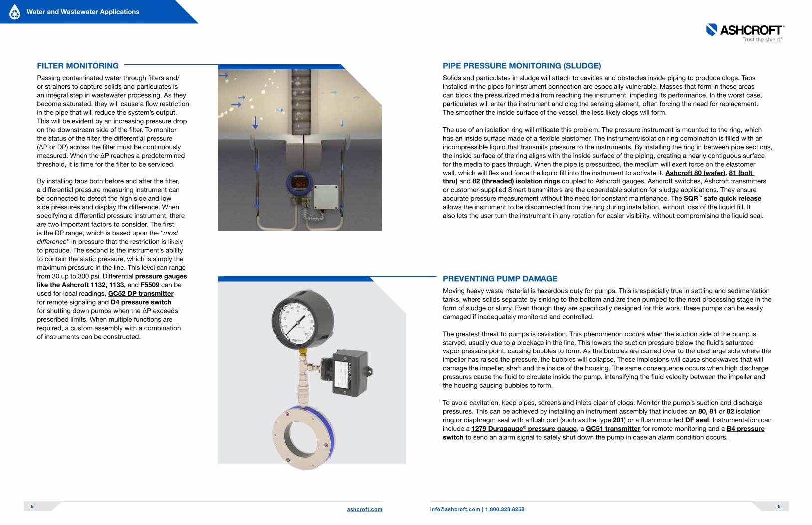
PREVENTING PUMP DAMAGEMoving heavy waste material is hazardous duty for pumps. This is especially true in settling and sedimentation tanks, where solids separate by sinking to the bottom and are then pumped to the next processing stage in the form of sludge or slurry. Even though they are specifically designed for this work, these pumps can be easily damaged if inadequately monitored and controlled.
The greatest threat to pumps is cavitation. This phenomenon occurs when the suction side of the pump is starved, usually due to a blockage in the line. This lowers the suction pressure below the fluid’s saturated vapor pressure point, causing bubbles to form. As the bubbles are carried over to the discharge side where the impeller has raised the pressure, the bubbles will collapse. These implosions will cause shockwaves that will damage the impeller, shaft and the inside of the housing. The same consequence occurs when high discharge pressures cause the fluid to circulate inside the pump, intensifying the fluid velocity between the impeller and the housing causing bubbles to form.
To avoid cavitation, keep pipes, screens and inlets clear of clogs. Monitor the pump’s suction and discharge pressures. This can be achieved by installing an instrument assembly that includes an 80, 81 or 82 isolation ring or diaphragm seal with a flush port (such as the type 201) or a flush mounted DF seal. Instrumentation can include a 1279 Duragauge® pressure gauge, a GC51 transmitter for remote monitoring and a B4 pressure switch to send an alarm signal to safely shut down the pump in case an alarm condition occurs.
[email protected] | 1.800.328.8258 9
FILTER MONITORINGPassing contaminated water through filters and/or strainers to capture solids and particulates is an integral step in wastewater processing. As they become saturated, they will cause a flow restriction in the pipe that will reduce the system’s output. This will be evident by an increasing pressure drop on the downstream side of the filter. To monitor the status of the filter, the differential pressure (∆P or DP) across the filter must be continuously measured. When the ∆P reaches a predetermined threshold, it is time for the filter to be serviced.
By installing taps both before and after the filter, a differential pressure measuring instrument can be connected to detect the high side and low side pressures and display the difference. When specifying a differential pressure instrument, there are two important factors to consider. The first is the DP range, which is based upon the “most difference” in pressure that the restriction is likely to produce. The second is the instrument’s ability to contain the static pressure, which is simply the maximum pressure in the line. This level can range from 30 up to 300 psi. Differential pressure gauges like the Ashcroft 1132, 1133, and F5509 can be used for local readings, GC52 DP transmitter for remote signaling and D4 pressure switch for shutting down pumps when the ∆P exceeds prescribed limits. When multiple functions are required, a custom assembly with a combination of instruments can be constructed.
PIPE PRESSURE MONITORING (SLUDGE)Solids and particulates in sludge will attach to cavities and obstacles inside piping to produce clogs. Taps installed in the pipes for instrument connection are especially vulnerable. Masses that form in these areas can block the pressurized media from reaching the instrument, impeding its performance. In the worst case, particulates will enter the instrument and clog the sensing element, often forcing the need for replacement. The smoother the inside surface of the vessel, the less likely clogs will form.
The use of an isolation ring will mitigate this problem. The pressure instrument is mounted to the ring, which has an inside surface made of a flexible elastomer. The instrument/isolation ring combination is filled with an incompressible liquid that transmits pressure to the instruments. By installing the ring in between pipe sections, the inside surface of the ring aligns with the inside surface of the piping, creating a nearly contiguous surface for the media to pass through. When the pipe is pressurized, the medium will exert force on the elastomer wall, which will flex and force the liquid fill into the instrument to activate it. Ashcroft 80 (wafer), 81 (bolt thru) and 82 (threaded) isolation rings coupled to Ashcroft gauges, Ashcroft switches, Ashcroft transmitters or customer-supplied Smart transmitters are the dependable solution for sludge applications. They ensure accurate pressure measurement without the need for constant maintenance. The SQR™ safe quick release allows the instrument to be disconnected from the ring during installation, without loss of the liquid fill. It also lets the user turn the instrument in any rotation for easier visibility, without compromising the liquid seal.
Water and Wastewater Applications

ashcroft.com 10 [email protected] | 1.800.328.8258 11
� Liquid Fill: Filling the gauge with a viscous liquid stabilizes the pointer when the gauge is subjected to vibration and pulsation. Choose from a variety of liquids depending upon the anticipated operating temperature and process compatibility in the event of a breach.
� PLUS!™ Performance option: An engineered dampening media encapsulates the gauge’s pinion to slow down unwanted pointer motion caused by vibration. Precludes the need for liquid fill in many applications.
� Pulsation Dampener: An external device that protects the instrument from significant pressure pulses. Threaded onto the gauge’s inlet connection, a pulsation dampener will soften extreme pressure inputs to stabilize readings while extending an instrument’s service life. The 1106 pulsation dampener is designed for this purpose.
� Snubber: An external device that protects the instrument from significant pressure pulses or fluctuations by limiting the rate of flow. Threaded onto the gauge’s inlet connection, a snubber will soften extreme pressure inputs to stabilize readings while extending an instrument’s service life. 1112 and PD02 snubbers are recommended.
� All the instruments are activated through a single port, saving space
� Instead of attaching each instrument to its own diaphragm seal, only one seal may be necessary to protect the entire assembly, saving money
� Ashcroft will construct assemblies with the smart transmitter of your choice
� Each instrument can be calibrated after assembly and filling to ensure accuracy
� Procuring instruments and assemblies designed and built by one manufacturer ensures proper performance and cooperation between instruments and other devices
� Efficient configuration designs reduce piping and volume to minimize temperature effects and improve instrument responsiveness
It’s not easy to choose the right equipment — there are so many concerns. Your selection will affect installation, proper function and will help you to avoid the possibility of future malfunctions and failures.
Here are the top five factors to consider:
ENSURE STABLE READINGSGauges that exhibit pointer flutter due to pump pulsation or machine vibration are difficult to read and may suffer a reduced service life. This can be remedied by dampening the movement to stabilize the pointer or adding an external dampener. Consider these options:
Select the Right Equipment
Pressure switch for on/off or
high/low control
Diaphragm seal to isolate instrument
from pressure medium
Pressure gauge for local reading
Pressure transducer/transmitter for remote signaling
1
2
Water and Wastewater Applications
MULTIPLE MEASUREMENT AND CONTROL FUNCTIONS When one port is available to pressurize several instruments with unique functions, Ashcroft will construct a custom instrument assembly to consolidate all of the instrumentation onto one platform. This provides several important benefits:

ashcroft.com 12 [email protected] | 1.800.328.8258 13
KEEP INSTRUMENTS FROM CLOGGINGTo separate instruments from particulate-laden pressure media, isolation rings are mounted in between pipe segments so the ring’s inside surface is contiguous with the inside surface of the pipes. This eliminates cavities or obstructions that will accumulate media particulates to form clogs. The inside surface of the ring is a 360° elastomer that flexes under pressure, forcing fill-fluid into the pressure instrument, which is mounted to the outer surface of the ring. Three mounting styles, wafer, bolt thru and threaded and the optional safe quick release (SQR™) should be considered before purchasing.
ISOLATE INSTRUMENTS FROM HARSH MEDIAOffered in a variety of resistant materials, diaphragm seals provide the ultimate protection by isolating pressure instruments from harsh or corrosive process media. View the Ashcroft corrosion guide for media compatibility with instrument or isolator wetted parts. They are available in various styles and configurations. Before making a selection, consider these factors:
� What is the instrument it will be attached to?
� What is the pressure range?
� How does it mount to the process?
- Threaded fitting (Types 100, 101, 200, 201) - Flanged (Types DF, 102, 103, 202, 203) - In-line (flow-through) (Types 104, 105, 106,
107, 108, 204, 205, 206, 207)
� What is the process medium? (necessary to determine required wetted materials)
� Do you need corrosion resistant non-wetted parts to protect from environmental corrosives?
� What are the ambient temperatures? (affects both diaphragm and fill fluid selections)
� Does it require a flushing connection? (used if particulate media can cause clogging) (Types 101, 103, 201, 203, 301, 303, 312, 315, 401, 403, 501, 511)
� If a flushing connection is specified, will it also require a factory installed shut off valve? (Type V02 ball valve)
� Does it need to be “all welded”? (often applies to chemical systems) (Types 400, 401, 402, 403, 501, 511)
� Does it need to be welded to the instrument? (prevents possible leak path due to inadvertent gauge rotation)
CONTROL INFLOW TO YOUR INSTRUMENTSControlling pressure to your instruments allows for easier maintenance, protection from spikes and overpressure, safer system operation and more stable readings. They are useful with individual instruments or designed into instrument assemblies.
� Pressure limiting valve (PLV): Automatically closes when the pressure reaches a factory-set, field adjustable specified limit, isolating the instrument and preventing damage due to overpressure. The PL02 pressure limiting valve is recommended.
� Valves: Single shut-off, block & bleed and multi valve manifolds are installed to allow instrument removal, manual shutdown, pressure relief and pressure equalization in DP applications. V01, V02, V03 series valves are recommended.
Wafer: “Sandwiched” in between two flanges, the 80 isolation ring is a smaller diameter than the flanges bolt pattern. This type of connection is used when space is limited, usually when parallel pipes are very close. Although lighter weight, installation of this design requires a centering gauge (included with every wafer type isolation ring). It is compatible with ANSI/ASME B16. 5, 150 and 300-class flanges.
Bolt thru: Also compressed between two flanges, the 81 isolation ring is the same diameter as the pipe flanges, and flange bolts pass through it. It is heavier but easier to install as no centering is required. Also compatible with ASME B16.5 flanges.
Threaded: For smaller piping, the 82 isolation ring has threaded ends and an inside diameter that matches the pipe ID.
Instrument quick release connection: The SQR™ safe quick release located between the ring (or diaphragm seal) and the instrument enables the instrument to be rotated for easy viewing. Also, it allows removal of the instrument during shipping, installation or calibration, without losing the liquid fill in both the ring and the instrument.
Water and Wastewater Applications
3
4 5

ashcroft.com 14 [email protected] | 1.800.328.8258 15
Tank Level Gauge Industrial Digital Gauge
Model TC 2074, 2174
SpecificationsAccuracy ±1.6% of span ±0.25% full scale terminal point
Sizes 160 mm 3˝, 41/2˝
Ranges Pressure 60 in. H²0 to 360 in. H²0 Vacuum to 20,000 psi
Gauges
Ashcroft offers a complete line of instruments and other devices specifically intended for water and wastewater applications. Here is a quick summary of their specifications:
Recommended Ashcroft® Products
Process Gauges Stainless Steel Case Gauges (open front, ASME)
Stainless Steel Case Gauges (solid front, ASME)
Model 1259, 1279 25-35 1009, 45-60 1009 1209
SpecificationsAccuracy
±0.5% of span(ASME B40.100 Grade 2A)
±1% of span(ASME B40.100 Grade 1A)
±0.5% of span(ASME B40.100 Grade 2A)
Sizes 41/2˝ 21/2˝, 31/2˝, 41/2˝, 6˝ 41/2˝
Ranges PressureVacuum, compound,
15 to 20,000 psiVacuum, compound,
15 to 30,000 psiVacuum, compound,
15 to 30,000 psi
Stainless Steel Case Gauges (EN), open/solid
front (EN837-1)Differential Gauges Differential Gauges
Model T5500, T6500 1130, 1140 F5509, F6509
SpecificationsAccuracy
Standard: ±1% full scale (class 1); Optional 0.5% full scale
±2% ascending pressure full scale differential ±1.6% of span
Sizes100 mm or 160 mm,
Open front (T5500)/Solid front (T6500)2˝, 21/2˝, 31/2˝, 4˝, 41/2˝, 6˝ Stainless Steel 100 mm, 160 mm Stainless Steel
Ranges PressureVacuum, Compound, -30 in hg –
0, 0-20,000 psi0-5 psid to 150 psid 0-10 in. H²0 diff to 400 psid
Water and Wastewater Applications
Assemblies
Ashcroft offers the assembly of SMART transmitters to our diaphragm seals and isolation rings, ensuring that your pressure assemblies are tested for accuracy and leak integrity prior to shipment. Our transmitter assembly service helps take the guesswork out of specifying the correct pressure instrumentation and assembly orientation, while our Ashcroft instrumentation experts ensure that the instruments are compatible and properly calibrated to suit your application.
OVERVIEW
CODE DESCRIPTION
CD-1 Standard Certificate of Conformance to Specifications and/or Drawings
C4 Individual Certified Calibration Chart per ASME B 40.100:2013, N.I.S.T traceable
C3 Actual Material Certification per EN 10204 3.1
CD-6 Typical Material Certification per EN 10204 2.2
1H Hydrostatic/Pneumatic Testing of Pressure Gauge Assemblies
HY Hydrostatic/Pneumatic Testing of Instrument System
ML Mass Spectrometer Leak Test
MQ Positive Material Identification (PMI)
W2 Dye Penetrant Test of Bourdon Tube
NH Wired Stainless Steel Tag
Documentation & TaggingThe most common documentation and tags include the following codes:
See datasheets at ashcroft.com for complete product specifications.See datasheets at ashcroft.com for complete product specifications.

ashcroft.com 16 [email protected] | 1.800.328.8258 17
Transmitters
Pressure Transmitter
Low Pressure Differential Pressure
Transmitter
General Purpose Industrial Pressure
Transducer
Submersible Pressure Transmitter
Model GC51 GC52 E2G SL17
Specifications
Accuracy ±0.25% of span (URL) ±0.25% of span (URL)±0.25%, ±0.50%, and ±1.0% of span
±0.25% of span for ranges > 1.5 psi, ±0.5% for 1.5 psi
Output 4-20 mA (2 wire) 4-20 mA (2 wire)4-20 mA, 20-4 mA, 1-5 Vdc, 1-6 Vdc, 0-5 Vdc, 0-10 Vdc, 1-11 Vdc, 0.1-5 Vdc,
0.1-10 Vdc, and 0.5-4.5 Vdc4-20 mA
RangesPressure
Ranges: 50 psi to 7500 psi, 15# & VAC to 50# &
VAC (Compound)
Unidirectional: 4 in. H²0 to 400 in. H²0 D, Bidirectional ±4 in. H²0
to ±200 in. H²0 diff
15-300 psi absolute, compound to 300 psi gauge,1.5-20,000 psi gauge
1.5 to 300 psi or 700 ft. H²0
Operating Temperature
14°F to 140°F (-10°C to 60°C)
14°F to 140°F (-10°C to 60°C) -40°C to 257°F (-40°C to 125°C) 14°F to 104°F (-10°C to 40°C)
Recommended Ashcroft® Products
Switches
Seals
Flush Flanged Diaphragm Seals Threaded Diaphragm Seals Flanged Diaphragm Seals
Model DF 100, 200, 300 102, 202, 302
SpecificationsDiaphragm Material Variety of metallic wetted materials
Variety of metallic and elastomeric materials
Variety of metallic and elastomeric materials
Bottom Housing Material
Flush design eliminates the need for a bottom housing
Variety of metallic and non-metallic materials
Variety of metallic and non-metallic materials
Ranges Pressure Ratings 150 to 2500 class ASME flanges 500, 2500 and 5000 psi 150 to 1500 class ASME flanges
All-Welded Seals, Threaded, Flanged
All-Welded Seals, Threaded
Isolation Rings, Wafer, Flanged, Threaded
Model 400-401, 402-403 510, 511 80, 81, 82
SpecificationsDiaphragm Material Variety of metallic wetted materials Variety of metallic diaphragms Variety of elastomeric liners
Bottom Housing Material
Variety of metallic materials Variety of metallic materialsVariety of metallic and
non-metallic end plates
Ranges Pressure Ratings 4,400 psi, 150-1500 class ASME flanges 1500 psi (10,000 psi optional) 150 to 300 class ASME flanges
Water and Wastewater Applications
Pulsation Dampener Snubber Pressure Limiting
Valve (PLV) Ball Valve
Model 1106 1112, PD02 PL02 V02
SpecificationsMaterials Brass, Steel, Stainless Steel Brass, Stainless Steel, Monel 316Ti Stainless Steel 316 Stainless Steel
Connections 1/4˝ and 1/2˝ 1/4˝ and 1/2˝ 1/4 NPT, 1/2 NPT 1/2 NPTF
Ranges Maximum Pressure 5,000 psi 15,000 psi 14,500 psi 6092 psi
B-Series Pressure Switch
B-Series Differential Switch
L-Series Pressure Switch
L-Series Differential Pressure Switch
Model B4 D4 LP LD
Specifications
EnclosureWatertight epoxy coated
aluminum NEMA 4, 4X, IP66Watertight epoxy coated
aluminum NEMA 4, 4X, IP66NEMA 4X/IP66 NEMA 4X/IP66
Function
Single setpoint, fixed deadband, SPDT (or) single setpoint, fixed deadband, (2) SPDT (DPDT action)
Single setpoint, fixed deadband, SPDT (or) single setpoint, fixed deadband, (2)
SPDT (DPDT action)
Dual independent setpoints, fixed deadband
Single setpoint, adjustable deadband Single setpoint, fixed deadband
Dual independent setpoints, fixed deadband
Single setpoint, adjustable deadbandSingle setpoint, fixed deadband
Ranges Pressure Vacuum to 3,000 psi 10 in. H20 diff thru 600 psid Vac to 3,000 psi 10 in. H20 diff thru 400 psid
Accessories
1 Valve Manifold 2 Valve Manifold 3 Valve Manifold Monoflange
Model V01 V02 V03 Monoflange-V02
SpecificationsMaterials 316L Stainless Steel 316L Stainless Steel 316L Stainless Steel 316L Stainless Steel
ConnectionsProcess Conn: 1/2 NPTM or 1/2
NPTF, Instrument Conn: 1/2 NPTFProcess Conn: 1/2 NPTM,
Instrument Conn: 1/2 NPTFProcess Conn: 1/4 NPTF
or 1/2 NPTFFlanged Process Connection: 1/2˝ - 3˝ raised face, ring joint, 1/2˝ - 3˝ raised face, ring joint
Ranges Maximum Pressure 6000 psi at 100°F (38°C) 6092 psi at 140°F (60°C) 6000 psi at 100°F (38°C) 6092 psi at 220°F (104°C)
See datasheets at ashcroft.com for complete product specifications.See datasheets at ashcroft.com for complete product specifications.

ashcroft.com 18
Let Us Be Your Single-Source SolutionWe share a similar mission. Yours is to keep it all moving, ours is to constantly push the limits of innovation and deliver the world’s most trusted measurement instruments. Combined, they add up to solutions, ensuring that your system will operate reliably and perform with maximum efficiency.
Mission accomplished!
Recommended Ashcroft® Products
Water and Wastewater Applications
Contact us to help you take-on your next project:
1.800.328.8258
ashcroft.com
Bi-metal Thermometers
Gas Actuated Thermometers RTD Probes Thermocouple
Probes
Model Model E Duratemp® / S5500 AR10, AR20 AT10, AT20, AT30
Specifications
Accuracy ±1.0% of span±0.5% of span ±1.0% of span ±1.6% of span
Class A Class B
Class 1 Class 2 Class 3
Standard Special
Size & Case Features
2˝, 3˝, 5˝ Stainless Steel,
Hermetically Sealed
41/2˝, 100 mm, 160 mm, Stainless Steel
N/A N/A
Stem Lengths 21/2˝ to 60˝Direct 6˝ to 36˝, Remote 5´ to 80´
2˝ to 120˝ 51 mm to 3,048 mm
2˝ to 120˝ 51 mm to 3,048 mm
Ranges Temperature -80°F to 1000°F, -50°C to 500°C-320°F to 1500°F, -195°C to 815°C
Pt 100 -200 to +600°C Pt 1000 -40 to +600°C
Type J -40 to +750°C Type E -200 to +800°C
Type K -200 to +1100°C Type N -200 to +1100°C"
Temperature
Thermowell Thermowell Thermowell
Model Flanged Threaded Sanitary
Specifications
Process Connection 1˝, 1.5˝, 2˝, 3˝, & 4˝ Pipe Size 1/2, 3/4, 1 NPT 1˝, 1.5˝, & 2˝ Tri-Clamp
Overall Length Min U dimension 2˝ Min U dimension 1˝ Min U dimension 1˝
Materials Variety of metallic materials Variety of metallic materials 304 & 316 Stainless Steel
Thermowell Thermowell Thermowell
Model Socket Weld Weld-In Van Stone
Specifications
Process Connection 3/4˝ & 1˝ Pipe Size 1.5˝ Pipe Size 1˝, 1.5˝, 2˝, 3˝, & 4˝ Pipe Size
Overall Length Min U dimension 1" Min U dimension 1˝ Min U dimension 2˝
Materials Variety of metallic materials Variety of metallic materials Variety of metallic materials
Support Solutions for EPC and Large Projects
Ashcroft provides support services to customers coming from engineering, procurement, and construction (EPC) companies, which serve as contractors for construction and other large-scale industrial projects.
Our knowledgeable and skilled global support specialists assist these customers throughout their projects, from initial concept to project completion. Equipped with state-of-the-art electronic document control and project management software, we participate in industrial projects around the world by identifying and providing successful instrument solutions.
See datasheets at ashcroft.com for complete product specifications.

All specifications are subject to change without notice.All sales subject to standard terms and conditions.©2021 Ashcroft Inc. water_wastewater_br_RevB_03-02-21
TRADEMARK ACKNOWLEDGEMENTS
Ashcroft® is a registered trademark of Ashcroft Inc. 17-4-PH® is a registered trademark of AK Steel Corporation Carpenter 20CB-3LR® is a registered trademark of Carpenter Technology Halar® is a registered trademark of Solvay Solexis Inc. Hastelloy® is a registered trademark of Haynes International Inc. Inconel® & Monel® are registered trademarks of Special Metals Corporation Kalrez® is a registered trademark of E.I. DuPont de Nemours, Inc. Kynar® is a registered trademark of Arkema, Inc. Viton® & Teflon® are registered trademarks of The Chemours Company FC. LLC.
Learn more about water and wastewater applications and associated Ashcroft instrumentation by visiting our website:
ashcroft.com
80/81/82 Isolation Rings
SL17 Submersible Pressure Transmitter
All About Water & Wastewater
Support Solutions for EPC and Large Projects