wastewater treatment processes and systems
TRANSCRIPT


USEPA Onsite Wastewater Treatment Systems Manual 4-1
Chapter 4: Treatment Processes and Systems
4.1 Introduction
This chapter contains information on individual
onsite/decentralized treatment technologies or unit
processes. Information on typical application,
design, construction, operation, maintenance, cost,
and pollutant removal effectiveness is provided for
most classes of treatment units and their related
processes. This information is intended to be used
in the preliminary selection of a system of treat-
ment unit processes that can be assembled to
achieve predetermined pollutant discharge concen-
trations or other specific performance require-
ments. Complete design specifications for unit
processes and complete systems are not included in
the manual because of the number of processes and
process combinations and the wide variability in
their application and operation under various site
conditions. Designers and others who require more
detailed technical information are referred to such
sources.
Chapter 4 is presented in two main sections. The
first section contains information about conven-
tional (soil-based or subsurface wastewater infiltra-
tion) systems, referred to as SWISs in this docu-
ment. Both gravity-driven and mechanized SWISs
are covered in this section of chapter 4. The second
section contains a general introduction to sand
filters (including other media), and a series of fact
sheets on treatment technologies, alternative
systems (e.g., fixed-film and suspended growth
systems, evapotranspiration systems, and other
applications), and special issues pertaining to the
design, operation, and maintenance of onsite
wastewater treatment systems (OWTSs). This
Chapter 4
Treatment processes and systems
approach was used because the conventional system
is the most economical and practical system type
that can meet performance requirements in many
applications.
The first section is further organized to provide
information about the major components of a
conventional system. Given the emphasis in this
manual on the design boundary (performance-
based) approach to system design, this section was
structured to lead the reader through a discussion of
system components by working backwards from
the point of discharge to the receiving environment
to the point of discharge from the home or other
facility served by the onsite system. Under this
approach, soil infiltration issues are discussed first,
the distribution piping to the infiltration system
including graveless sytems is addressed next, and
matters related to the most common preliminary
treatment device, the septic tank, are covered last.
The fact sheets in the second section of this chapter
describe treatment technologies and discuss special
issues that might affect system design, perfor-
mance, operation, and maintenance. These treat-
ment technologies are often preceded by a septic
tank and can include a subsurface wastewater
infiltration system. Some treatment technologies
may be substituted for part or all of the conven-
tional system, though nearly all alternative ap-
proaches include a septic tank for each facility
being served. Fact sheets are provided for the more
widely used and successful treatment technologies,
such as sand filters and aerobic treatment units.
4.1 Introduction
4.2 Conventional systems and treatment options
4.3 Subsurface wastewater infiltration
4.4 Design considerations
4.5 Construction management and contingency options
4.6 Septic tanks
4.7 Sand/media filters
4.8 Aerobic Treatment Units
Chapter 4: Treatment Processes and Systems
4-2 USEPA Onsite Wastewater Treatment Systems Manual
The component descriptions provided in this
chapter are intended to assist the reader in screen-
ing components and technologies for specific
applications. Chapter 5 presents a strategy and
procedures that can be used to screen and select
appropriate treatment trains and their components
for specific receiver sites. The reader should review
chapter 5 before selecting system components.
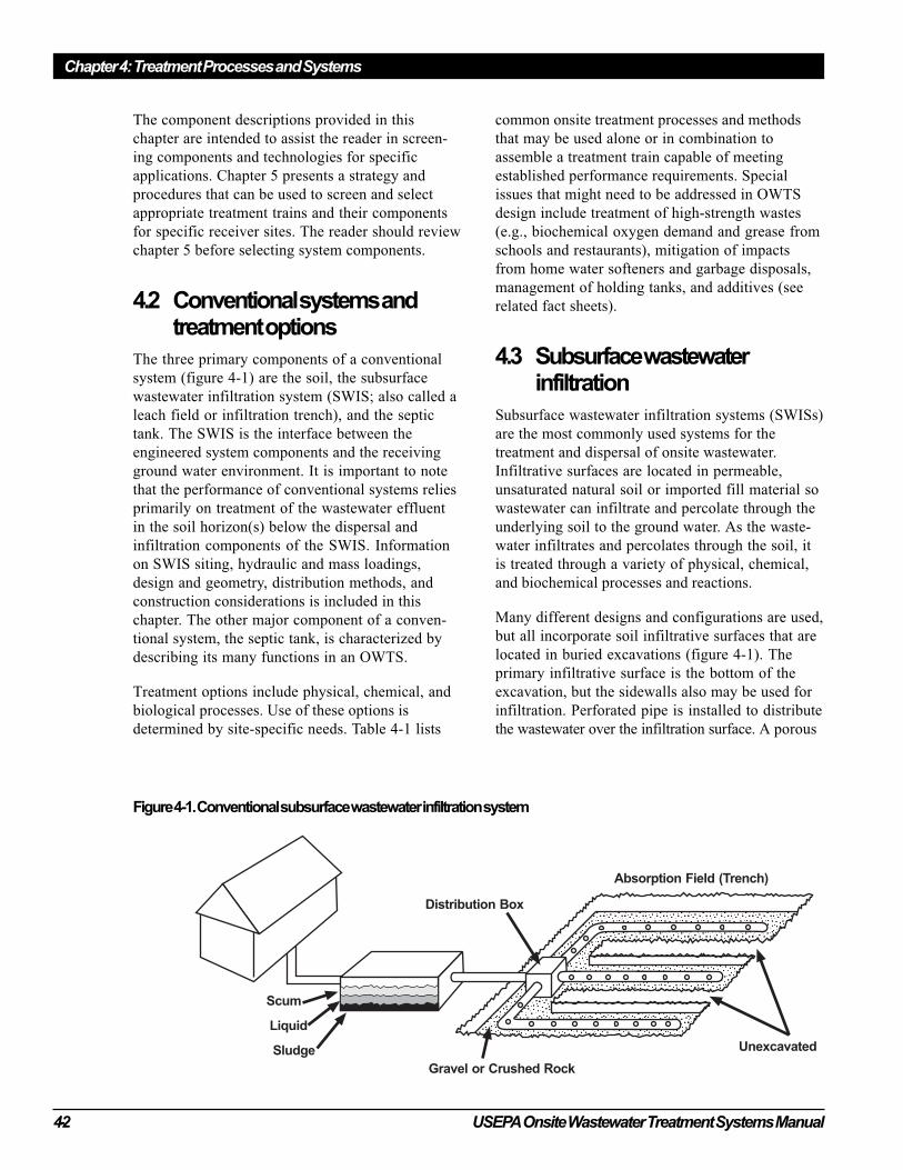
4.2 Conventional systems andtreatment options
The three primary components of a conventional
system (figure 4-1) are the soil, the subsurface
wastewater infiltration system (SWIS; also called a
leach field or infiltration trench), and the septic
tank. The SWIS is the interface between the
engineered system components and the receiving
ground water environment. It is important to note
that the performance of conventional systems relies
primarily on treatment of the wastewater effluent
in the soil horizon(s) below the dispersal and
infiltration components of the SWIS. Information
on SWIS siting, hydraulic and mass loadings,
design and geometry, distribution methods, and
construction considerations is included in this
chapter. The other major component of a conven-
tional system, the septic tank, is characterized by
describing its many functions in an OWTS.
Treatment options include physical, chemical, and
biological processes. Use of these options is
determined by site-specific needs. Table 4-1 lists
common onsite treatment processes and methods
that may be used alone or in combination to
assemble a treatment train capable of meeting
established performance requirements. Special
issues that might need to be addressed in OWTS
design include treatment of high-strength wastes
(e.g., biochemical oxygen demand and grease from
schools and restaurants), mitigation of impacts
from home water softeners and garbage disposals,
management of holding tanks, and additives (see
related fact sheets).
4.3 Subsurface wastewaterinfiltration
Subsurface wastewater infiltration systems (SWISs)
are the most commonly used systems for the
treatment and dispersal of onsite wastewater.
Infiltrative surfaces are located in permeable,
unsaturated natural soil or imported fill material so
wastewater can infiltrate and percolate through the
underlying soil to the ground water. As the waste-
water infiltrates and percolates through the soil, it
is treated through a variety of physical, chemical,
and biochemical processes and reactions.
Many different designs and configurations are used,
but all incorporate soil infiltrative surfaces that are
located in buried excavations (figure 4-1). The
primary infiltrative surface is the bottom of the
excavation, but the sidewalls also may be used for
infiltration. Perforated pipe is installed to distribute
the wastewater over the infiltration surface. A porous
Figure 4-1. Conventional subsurface wastewater infiltration system

USEPA Onsite Wastewater Treatment Systems Manual 4-3
Chapter 4: Treatment Processes and Systems
Table 4-1. Commonly used treatment processes and optional treatment methods
Chapter 4: Treatment Processes and Systems
4-4 USEPA Onsite Wastewater Treatment Systems Manual
medium, typically gravel or crushed rock, is placed
in the excavation below and around the distribution
piping to support the pipe and spread the localized
flow from the distribution pipes across the excavation
cavity. Other gravelless or “aggregate-free” system
components may be substituted. The porous
medium maintains the structure of the excavation,
exposes the applied wastewater to more infiltrative
surface, and provides storage space for the waste-
water within its void fractions (interstitial spaces,
typically 30 to 40 percent of the volume) during peak
flows with gravity systems. A permeable geotextile
fabric or other suitable material is laid over the porous
medium before the excavation is backfilled to prevent
the introduction of backfill material into the porous
medium. Natural soil is typically used for backfilling,
and the surface of the backfill is usually slightly
mounded and seeded with grass.
Subsurface wastewater infiltration systems provide
both dispersal and treatment of the applied waste-
water. Wastewater is transported from the infiltration
system through three zones (see chapter 3). Two of
these zones, the infiltration zone and vadose zone, act
as fixed-film bioreactors. The infiltration zone, which
is only a few centimeters thick, is the most biologi-
cally active zone and is often referred to as the
“biomat.” Carbonaceous material in the wastewater is
quickly degraded in this zone, and nitrification occurs
immediately below this zone if sufficient oxygen is
present. Free or combined forms of oxygen in the soil
must satisfy the oxygen demand generated by the
microorganisms degrading the materials. If sufficient
oxygen is not present, the metabolic processes of the
microorganisms can be reduced or halted and both
treatment and infiltration of the wastewater will be
adversely affected (Otis, 1985). The vadose (unsatur-
ated) zone provides a significant pathway for oxygen
diffusion to reaerate the infiltration zone (Otis, 1997,
Siegrist et al., 1986). Also, it is the zone where most
sorption reactions occur because the negative moisture
potential in the unsaturated zone causes percolating
water to flow into the finer pores of the soil, resulting
in greater contact with the soil surfaces. Finally, much
of the phosphorus and pathogen removal occurs in
this zone (Robertson and Harman, 1999; Robertson et
al., 1998; Rose et al., 1999; Yates and Yates, 1988).
4.3.1 SWIS designs
There are several different designs for SWISs.
They include trenches, beds, seepage pits, at-grade
systems, and mounds. SWIS applications differ in
their geometry and location in the soil profile.
Trenches have a large length-to-width ratio, while
beds have a wide, rectangular or square geometry.
Seepage pits are deep, circular excavations that rely
almost completely on sidewall infiltration. Seepage
pits are no longer permitted in many jurisdictions
because their depth and relatively small horizontal
profile create a greater point-source pollutant
loading potential to ground water than other
geometries. Because of these shortcomings, seepage
pits are not recommended in this manual.
Infiltration surfaces may be created in natural soil
or imported fill material. Most traditional systems
are constructed below ground surface in natural
soil. In some instances, a restrictive horizon above
a more permeable horizon may be removed and the
excavation filled with suitable porous material in
which to construct the infiltration surface (Hinson
et al., 1994). Infiltration surfaces may be con-
structed at the ground surface (“at-grades”) or
elevated in imported fill material above the natural
soil surface (“mounds”). An important difference
between infiltration surfaces constructed in natural
soil and those constructed in fill material is that a
secondary infiltrative surface (which must be
considered in design) is created at the fill/natural
soil interface. Despite the differences between the
types of SWISs, the mechanisms of treatment and
dispersal are similar.
4.3.2 Typical applications
Subsurface wastewater infiltration systems are
passive, effective, and inexpensive treatment
systems because the assimilative capacity of many
soils can transform and recycle most pollutants
found in domestic and commercial wastewaters.
SWISs are the treatment method of choice in rural,
unsewered areas. Where point discharges to surface
waters are not permitted, SWISs offer an alterna-
tive if ground water is not closely interconnected
with surface water. Soil characteristics, lot size, and
the proximity of sensitive water resources affect the
use of SWISs. Table 4-2 presents characteristics for
typical SWIS applications and suggests applications
to avoid. Local codes should be consulted for
special requirements, restrictions, and other
relevant information.
USEPA Onsite Wastewater Treatment Systems Manual 4-5
Chapter 4: Treatment Processes and Systems
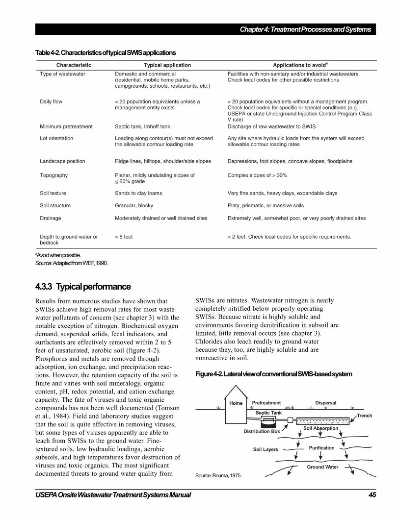
4.3.3 Typical performance
Results from numerous studies have shown that
SWISs achieve high removal rates for most waste-
water pollutants of concern (see chapter 3) with the
notable exception of nitrogen. Biochemical oxygen
demand, suspended solids, fecal indicators, and
surfactants are effectively removed within 2 to 5
feet of unsaturated, aerobic soil (figure 4-2).
Phosphorus and metals are removed through
adsorption, ion exchange, and precipitation reac-
tions. However, the retention capacity of the soil is
finite and varies with soil mineralogy, organic
content, pH, redox potential, and cation exchange
capacity. The fate of viruses and toxic organic
compounds has not been well documented (Tomson
et al., 1984). Field and laboratory studies suggest
that the soil is quite effective in removing viruses,
but some types of viruses apparently are able to
leach from SWISs to the ground water. Fine-
textured soils, low hydraulic loadings, aerobic
subsoils, and high temperatures favor destruction of
viruses and toxic organics. The most significant
documented threats to ground water quality from
SWISs are nitrates. Wastewater nitrogen is nearly
completely nitrified below properly operating
SWISs. Because nitrate is highly soluble and
environments favoring denitrification in subsoil are
limited, little removal occurs (see chapter 3).
Chlorides also leach readily to ground water
because they, too, are highly soluble and are
nonreactive in soil.
Figure 4-2. Lateral view of conventional SWIS-based system
Source: Bouma, 1975.
aAvoid when possible.
Source: Adapted from WEF, 1990.
Table 4-2. Characteristics of typical SWIS applications
Chapter 4: Treatment Processes and Systems
4-6 USEPA Onsite Wastewater Treatment Systems Manual
Dispersion of SWIS percolate in the ground water
is often minimal because most ground water flow is
laminar. The percolate can remain for several
hundred feet as a distinct plume in which the solute
concentrations remain above ambient ground water
concentrations (Robertson et al., 1989, Shaw and
Turyk, 1994). The plume descends in the ground
water as the ground water is recharged from the
surface, but the amount of dispersion of the plume
can be variable. Thus, drinking water wells some
distance from a SWIS can be threatened if they are
directly in the path of a percolate plume.
4.4 Design considerations
Onsite wastewater treatment system designs vary
according to the site and wastewater characteristics
encountered. However, all designs should strive to
incorporate the following features to achieve
satisfactory long-term performance:
• Shallow placement of the infiltration surface
(< 2 feet below final grade)
• Organic loading comparable to that of septic
tank effluent at its recommended hydraulic
loading rate
• Trench orientation parallel to surface contours
• Narrow trenches (< 3 feet wide)
• Timed dosing with peak flow storage
• Uniform application of wastewater over the
infiltration surface
• Multiple cells to provide periodic resting,
standby capacity, and space for future repairs or
replacement
Based on the site characteristics, compromises to
ideal system designs are necessary. However, the
designer should attempt to include as many of the
above features as possible to ensure optimal long-
term performance and minimal impact on public
health and environmental quality.
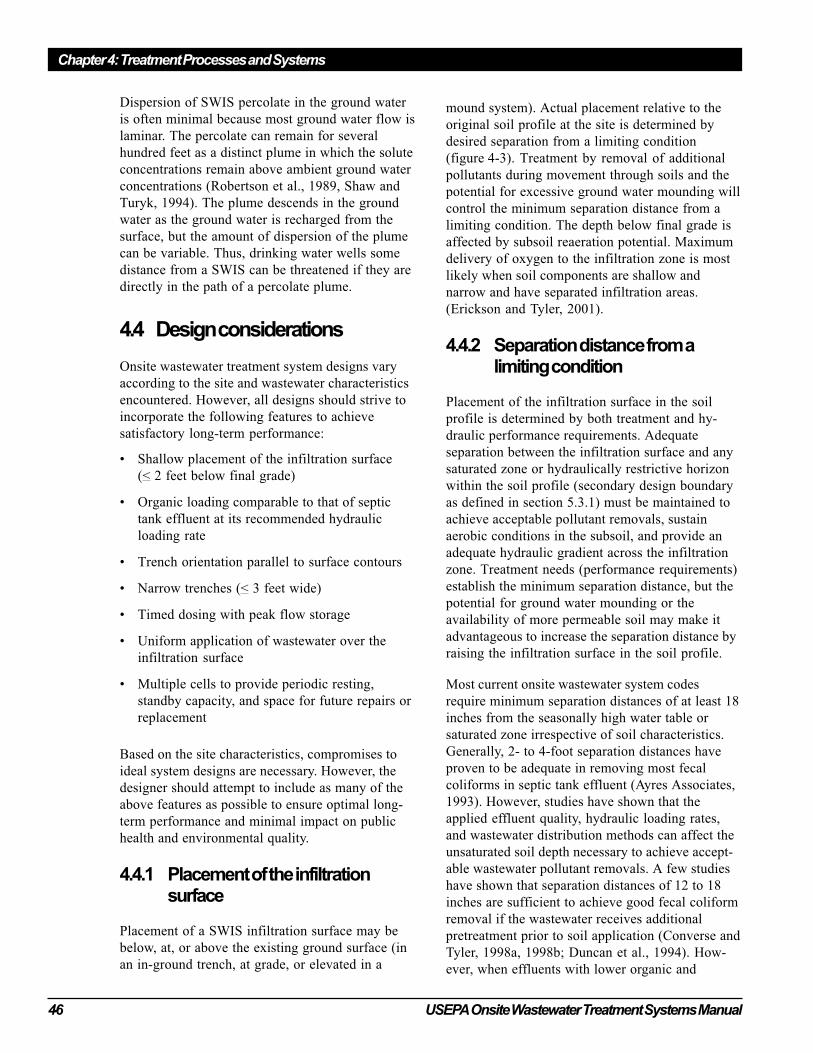
4.4.1 Placement of the infiltrationsurface
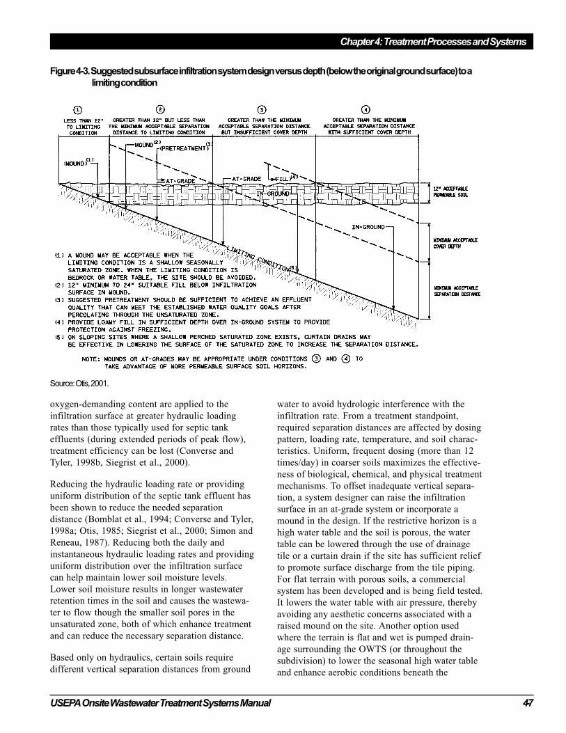
Placement of a SWIS infiltration surface may be
below, at, or above the existing ground surface (in
an in-ground trench, at grade, or elevated in a
mound system). Actual placement relative to the
original soil profile at the site is determined by
desired separation from a limiting condition
(figure 4-3). Treatment by removal of additional
pollutants during movement through soils and the
potential for excessive ground water mounding will
control the minimum separation distance from a
limiting condition. The depth below final grade is
affected by subsoil reaeration potential. Maximum
delivery of oxygen to the infiltration zone is most
likely when soil components are shallow and
narrow and have separated infiltration areas.
(Erickson and Tyler, 2001).
4.4.2 Separation distance from alimiting condition
Placement of the infiltration surface in the soil
profile is determined by both treatment and hy-
draulic performance requirements. Adequate
separation between the infiltration surface and any
saturated zone or hydraulically restrictive horizon
within the soil profile (secondary design boundary
as defined in section 5.3.1) must be maintained to
achieve acceptable pollutant removals, sustain
aerobic conditions in the subsoil, and provide an
adequate hydraulic gradient across the infiltration
zone. Treatment needs (performance requirements)
establish the minimum separation distance, but the
potential for ground water mounding or the
availability of more permeable soil may make it
advantageous to increase the separation distance by
raising the infiltration surface in the soil profile.
Most current onsite wastewater system codes
require minimum separation distances of at least 18
inches from the seasonally high water table or
saturated zone irrespective of soil characteristics.
Generally, 2- to 4-foot separation distances have
proven to be adequate in removing most fecal
coliforms in septic tank effluent (Ayres Associates,
1993). However, studies have shown that the
applied effluent quality, hydraulic loading rates,
and wastewater distribution methods can affect the
unsaturated soil depth necessary to achieve accept-
able wastewater pollutant removals. A few studies
have shown that separation distances of 12 to 18
inches are sufficient to achieve good fecal coliform
removal if the wastewater receives additional
pretreatment prior to soil application (Converse and
Tyler, 1998a, 1998b; Duncan et al., 1994). How-
ever, when effluents with lower organic and
USEPA Onsite Wastewater Treatment Systems Manual 4-7
Chapter 4: Treatment Processes and Systems
oxygen-demanding content are applied to the
infiltration surface at greater hydraulic loading
rates than those typically used for septic tank
effluents (during extended periods of peak flow),
treatment efficiency can be lost (Converse and
Tyler, 1998b, Siegrist et al., 2000).
Reducing the hydraulic loading rate or providing
uniform distribution of the septic tank effluent has
been shown to reduce the needed separation
distance (Bomblat et al., 1994; Converse and Tyler,
1998a; Otis, 1985; Siegrist et al., 2000; Simon and
Reneau, 1987). Reducing both the daily and
instantaneous hydraulic loading rates and providing
uniform distribution over the infiltration surface
can help maintain lower soil moisture levels.
Lower soil moisture results in longer wastewater
retention times in the soil and causes the wastewa-
ter to flow though the smaller soil pores in the
unsaturated zone, both of which enhance treatment
and can reduce the necessary separation distance.
Based only on hydraulics, certain soils require
different vertical separation distances from ground
water to avoid hydrologic interference with the
infiltration rate. From a treatment standpoint,
required separation distances are affected by dosing
pattern, loading rate, temperature, and soil charac-
teristics. Uniform, frequent dosing (more than 12
times/day) in coarser soils maximizes the effective-
ness of biological, chemical, and physical treatment
mechanisms. To offset inadequate vertical separa-
tion, a system designer can raise the infiltration
surface in an at-grade system or incorporate a
mound in the design. If the restrictive horizon is a
high water table and the soil is porous, the water
table can be lowered through the use of drainage
tile or a curtain drain if the site has sufficient relief
to promote surface discharge from the tile piping.
For flat terrain with porous soils, a commercial
system has been developed and is being field tested.
It lowers the water table with air pressure, thereby
avoiding any aesthetic concerns associated with a
raised mound on the site. Another option used
where the terrain is flat and wet is pumped drain-
age surrounding the OWTS (or throughout the
subdivision) to lower the seasonal high water table
and enhance aerobic conditions beneath the
Figure 4-3. Suggested subsurface infiltration system design versus depth (below the original ground surface) to a
limiting condition
Source: Otis, 2001.
Chapter 4: Treatment Processes and Systems
4-8 USEPA Onsite Wastewater Treatment Systems Manual
drainfield. These systems must be properly oper-
ated by certified operators and managed by a public
management entity since maintenance of off-lot
portions of the drainage network will influence
performance of the SWIS.
The hydraulic capacity of the site or the hydraulic
conductivity of the soil may increase the minimum
acceptable separation distance determined by
treatment needs. The soil below the infiltration
surface must be capable of accepting and transmit-
ting the wastewater to maintain the desired unsatur-
ated separation distance at the design hydraulic
loading rate to the SWIS. The separation distance
necessary for satisfactory hydraulic performance is
a function of the permeability of the underlying
soil, the depth to the limiting condition, the
thickness of the saturated zone, the percentage of
rocks in the soil, and the hydraulic gradient.
Ground water mounding analyses may be necessary
to assess the potential for the saturated zone to rise
and encroach upon the minimum acceptable
separation distance (see section 5.4). Raising the
infiltration surface can increase the hydraulic
capacity of the site by accommodating more
mounding. If the underlying soil is more slowly
permeable than soil horizons higher in the profile,
it might be advantageous to raise the infiltration
surface into the more permeable horizon where
higher hydraulic loading rates are possible (Hoover
et al., 1991; Weymann et al., 1998). A shallow
infiltration system covered with fill or an at-grade
system can be used if the natural soil has a shallow
permeable soil horizon (Converse et al., 1990;
Penninger, and Hoover, 1998). If more permeable
horizons do not exist, a mound system constructed
of suitable sand fill (figure 4-4) can provide more
permeable material in which to place the infiltra-
tion surface.
4.4.3 Depth of the infiltration surface
The depth of the infiltration surface is an important
consideration in maintaining adequate subsoil
aeration and frost protection in cold climates. The
maximum depth should be limited to no more than
3 to 4 feet below final grade to adequately reaerate
the soil and satisfy the daily oxygen demand of the
applied wastewater. The infiltrative surface depth
should be less in slowly permeable soils or soils
with higher ambient moisture. Placement below
this depth to take advantage of more permeable
soils should be resisted because reaeration of the
soil below the infiltration surface will be limited.
In cold climates, a minimum depth of 1 to 2 feet
may be necessary to protect against freezing.
Porous fill material can be used to provide the
necessary cover even with an elevated (at-grade or
mound) system if it is necessary to place the
infiltration surface higher.
4.4.4 Subsurface drainage
Soils with shallow saturated zones sometimes can
be drained to allow the infiltration surface to be
placed in the natural soil. Curtain drains, vertical
drains, underdrains, and mechanically assisted
commercial systems can be used to drain shallow
water tables or perched saturated zones. Of the
three, curtain drains are most often used in onsite
wastewater systems to any great extent. They can
be used effectively to remove water that is perched
over a slowly permeable horizon on a sloping site.
However, poorly drained soils often indicate other
soil and site limitations that improved drainage
alone will not overcome, so the use of drainage
enhancements must be carefully considered. Any
sloping site that is subject to frequent inundation
during prolonged rainfall should be considered a
candidate for upslope curtain drains to maintain
unsaturated conditions in the vadose zone.
Curtain drains are installed upslope of the SWIS to
intercept the permanent and perched ground water
flowing through the site over a restrictive horizon.
Perforated pipe is laid in the bottom of upslope
trenches excavated into the restrictive horizon. A
durable, porous medium is placed around the
piping and up to a level above the estimated
seasonally high saturated zone. The porous medium
intercepts the ground water and conveys it to the
drainage pipe (figure 4-5). To provide an outfall
for the drain, one or both ends of the pipe are
extended downslope to a point where it intercepts
the ground surface. When drainage enhancements
are used, the outlet and boundary conditions must
be carefully evaluated to protect local water
quality.
The drain should avoid capture of the SWIS
percolate plume and ground water infiltrating from
below the SWIS or near the end of the drain. A
separation distance between the SWIS and the drain
that is sufficient to prevent percolate from the

USEPA Onsite Wastewater Treatment Systems Manual 4-9
Chapter 4: Treatment Processes and Systems
SWIS from entering the drain should be main-
tained. The vertical distance between the bottom of
the SWIS and the drain and soil permeability
characteristics should determine this distance. As
the vertical distance increases and the permeability
decreases, the necessary separation distance in-
creases. A 10-foot separation is used for most
applications. Also, if both ends of the drain cannot
be extended to the ground surface, the upslope end
should be extended some distance along the surface
contour beyond the end of the SWIS. If not done,
ground water that seeps around the end of the drain
can render the drain ineffective. Similar cautions
should be observed when designing and locating
outlet locations for commercial systems on flat
sites.
The design of a curtain drain is based on the
permeability of the soil in the saturated zone, the
size of the area upslope of the SWIS that contrib-
utes water to the saturated zone, the gradient of the
drainage pipe, and a suitable outlet configuration.
Figure 4-4. Raising the infiltration surface with a typical mound system.
CurtainDrain
FillMaterial
PerchedWaterTable Gravel Filled
Above HighWater Table
Drainage Pipe
Impermeable Layer
AbsorptionTrenches
Fill
Figure 4-5. Schematic of curtain drain construction
Source: USEPA, 1980
Source: ASAE, Converse and Tyler, 1998b.
Chapter 4: Treatment Processes and Systems
4-10 USEPA Onsite Wastewater Treatment Systems Manual
If the saturated hydraulic conductivity is low and
the drainable porosity (the percentage of pore space
drained when the soil is at field capacity) is small,
even effectively designed curtain drains might have
limited effect on soil wetness conditions. Penninger
et al. (1998) illustrated this at a site with a silty
clay loam soil at field capacity that became com-
pletely re-saturated with as little as 1-inch of
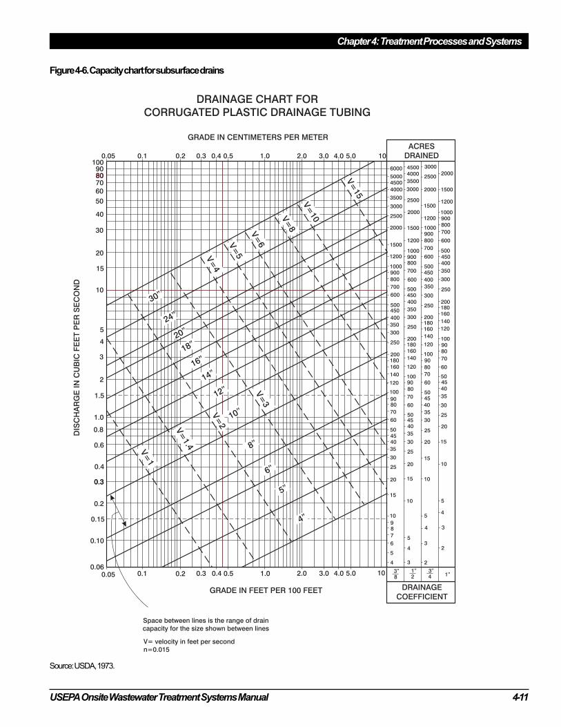
precipitation. Figure 4-6 provides a useful design
chart that considers most of these parameters. For
further design guidance, refer to the U.S. Depart-
ment of Agriculture’s Drainage of Agricultural
Land (USDA, 1973).
4.4.5 Sizing of the infiltration surface
The minimum acceptable infiltration surface area is
a function of the maximum anticipated daily
wastewater volume to be applied and the maximum
instantaneous and daily mass loading limitations of
the infiltration surface (see chapter 5). Both the
bottom and sidewall area of the SWIS excavation
can be infiltration surfaces; however, if the sidewall
is to be an active infiltration surface, the bottom
surface must pond. If continuous ponding of the
infiltration surface persists, the infiltration zone
will become anaerobic, resulting in loss of hydrau-
lic capacity. Loss of the bottom surface for infiltra-
tion will cause the ponding depth to increase over
time as the sidewall also clogs (Bouma, 1975; Keys
et al., 1998; Otis, 1977). If allowed to continue,
hydraulic failure of the system is probable. There-
fore, including sidewall area as an active infiltra-
tion surface in design should be avoided. If
sidewall areas are included, provisions should be
made in the design to enable removal of the ponded
system from service periodically to allow the
system to drain and the biomat to oxidize naturally.
Design flow
An accurate estimation of the design flow is critical
to infiltration surface sizing. For existing buildings
where significant changes in use are not expected,
water service metering will provide good estimates
for design. It is best to obtain several weeks of
metered daily flows to estimate daily average and
peak flows. For new construction, water use
metering is not possible and thus waste flow
projections must be made based on similar estab-
lishments. Tables of “typical” water use or waste-
water flows for different water use fixtures, usage
patterns, and building uses are available (see
section 3.3.1). Incorporated into these guidelines
are varying factors of safety. As a result, the use of
these guides typically provides conservatively high
estimates of maximum peak flows that may occur
only occasionally. It is critical that the designer
recognizes the conservativeness of these guides and
how they can be appropriately adjusted because of
their impacts on the design and, ultimately, perfor-
mance of the system.
Curtain drain design
Curtain drain design (see preceding figures) is dependent on the size of the contributing drainage area, the
amount of water that must be removed, the soil’s hydraulic properties, and the available slope of the site.
The contributing drainage area is estimated by outlining the capture zone on a topographic map of the site.
Drainage boundaries are determined by extending flow lines perpendicular to the topographic contours upslope
from the drain to natural divides (e.g., ridge tops) or natural or man-made “no-flow” boundaries (e.g., rock
outcrops, major roads). The amount of water that must be removed is an estimate of the volume of precipitation
that would be absorbed by the soil after a rainfall event. This is called the drainage coefficient, which is expressed
as the depth of water to be removed over a specified period of time, typically 24 hours. Soil structure, texture,
bulk density, slope, and vegetated cover all affect the volume of water to be drained.
The slope of the drain can be determined after the upslope depth of the drain invert and the outfall invert are
established. These can be estimated from the topographic map of the site. The contributing drainage area, water
volume to be removed, and slope of the drain are estimated. Figure 4-6 can be used to determine the drain
diameter. For example, the diameter of a curtain drain that will drain an area upslope of 50 acres with a drainage
coefficient of ¾ inch on a slope of 5 percent would be 8 inches (see figure). At 0.5 percent, the necessary drain
diameter would be 12 inches.
USEPA Onsite Wastewater Treatment Systems Manual 4-11
Chapter 4: Treatment Processes and Systems
DRAINAGE CHART FOR
CORRUGATED PLASTIC DRAINAGE TUBING
GRADE IN CENTIMETERS PER METER
0.05 0.1 0.2 0.3 0.4 0.5 1.0 2.0 3.0 5.04.0 101009080807060
50
40
30
20
15
10
5
4
3
2
1.5
1.0
0.8
0.6
0.4
0.3
0.15
0.3
0.2
0.10
0.060.05 0.1 0.2 0.3 0.4 0.5 1.0 2.0 3.0 4.0 5.0 10
GRADE IN FEET PER 100 FEET
Space between lines is the range of drain
capacity for the size shown between lines
V= velocity in feet per second
n=0.015
DIS
CH
AR
GE
INC
UB
ICF
EE
TP
ER
SE
CO
ND
ACRES
DRAINED
5000
6000
4500
4000
3500
3000
2500
2000
1500
1200
1000900
800
700
600
500450
400
350
300
250
200180160
140
120
100
9080
70
60
504540
35
30
25
20
15
10
98
7
6
5
4
4
4
4
5
5
510
10
10
15
15
15
20
20
20
25
25
25
30
30
30
35
35
35
40
40
40
45
45
45
50
50
50
60
60
60
70
70
70
80
80
80
90
90
90
100
100
100
120
120
120
140
140
140
160
160
160
180
180
200
200
200
250
250
250
300
300
300
350
350
350
400
400
400
450
450
450
500
500
500
600
600
600
700
700
700
800
800
800
900
900
900
1000
1000
1000
1200
1200
1200
1500
1500
1500
2000
2000
2000
2500
2500
3000
3000
3500
40004500
3
3
3
2
2
1”3”8
1”2
3”4
DRAINAGE
COEFFICIENT
30”
24”
20”
18”
16”
14”
12”
10”
8”
6”
5”
4”
V=
2
V=
1
V=
1.4
V=
3
V=
4
V=
5
V=
6
V=
8
V=
10
V=
15
180
Figure 4-6. Capacity chart for subsurface drains
Source: USDA, 1973.
Chapter 4: Treatment Processes and Systems
4-12 USEPA Onsite Wastewater Treatment Systems Manual
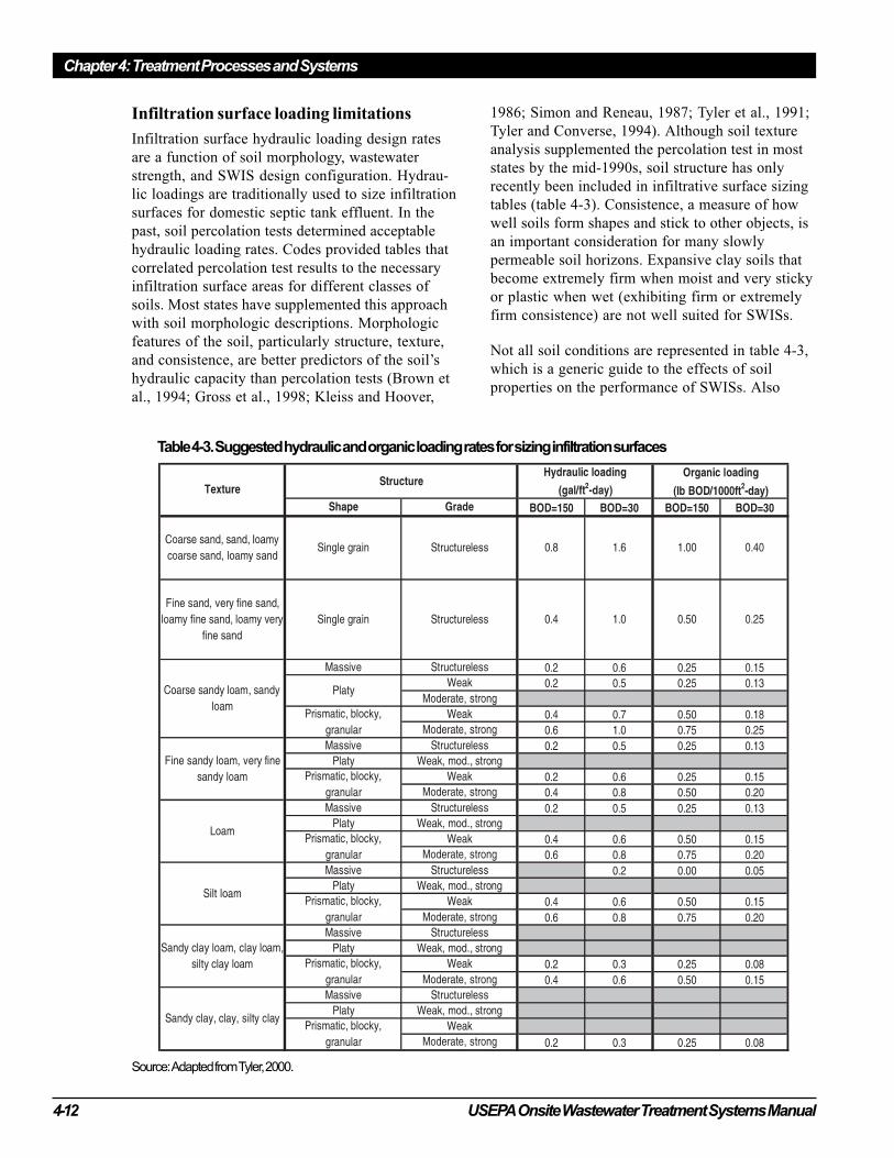
Table 4-3. Suggested hydraulic and organic loading rates for sizing infiltration surfaces
Source: Adapted from Tyler, 2000.
Infiltration surface loading limitations
Infiltration surface hydraulic loading design rates
are a function of soil morphology, wastewater
strength, and SWIS design configuration. Hydrau-
lic loadings are traditionally used to size infiltration
surfaces for domestic septic tank effluent. In the
past, soil percolation tests determined acceptable
hydraulic loading rates. Codes provided tables that
correlated percolation test results to the necessary
infiltration surface areas for different classes of
soils. Most states have supplemented this approach
with soil morphologic descriptions. Morphologic
features of the soil, particularly structure, texture,
and consistence, are better predictors of the soil’s
hydraulic capacity than percolation tests (Brown et
al., 1994; Gross et al., 1998; Kleiss and Hoover,
1986; Simon and Reneau, 1987; Tyler et al., 1991;
Tyler and Converse, 1994). Although soil texture
analysis supplemented the percolation test in most
states by the mid-1990s, soil structure has only
recently been included in infiltrative surface sizing
tables (table 4-3). Consistence, a measure of how
well soils form shapes and stick to other objects, is
an important consideration for many slowly
permeable soil horizons. Expansive clay soils that
become extremely firm when moist and very sticky
or plastic when wet (exhibiting firm or extremely
firm consistence) are not well suited for SWISs.
Not all soil conditions are represented in table 4-3,
which is a generic guide to the effects of soil
properties on the performance of SWISs. Also
USEPA Onsite Wastewater Treatment Systems Manual 4-13
Chapter 4: Treatment Processes and Systems
available are many other state and local guides that
include loadings for soils specific to local geomor-
phology. North Carolina, for example, uses the
long-term acceptance rate (LTAR) for soil load-
ings, which is the volume of wastewater that can be
applied to a square foot of soil each day over an
indefinite period of time such that the effluent
from the onsite system is absorbed and properly
treated (North Carolina DEHNR, 1996). In the
North Carolina rules, LTAR and loading rate values
are the same.
Increasingly, organic loading is being used to size
infiltration surfaces. Based on current understand-
ing of the mechanisms of SWIS operation, organic
loadings and the reaeration potential of the subsoil
to meet the applied oxygen demand are critical
considerations in successful SWIS design. Anaero-
bic conditions are created when the applied oxygen
demand exceeds what the soil is able to supply by
diffusion through the vadose zone (Otis, 1985,
1997; Siegrist et al., 1986). The facultative and
anaerobic microorganisms that are able to thrive in
this environment are less efficient in degrading the
waste materials. The accumulating waste materials
and the metabolic by-products cause soil clogging
and loss of infiltrative capacity.
Further, higher forms of soil fauna that would help
break up the biomat (e.g., worms, insects, non-
wetland plants) and would be attracted to the
carbon and nutrient-rich infiltration zone are
repelled by the anoxic or anaerobic environment. If
wastewater application continues without ample
time to satisfy the oxygen demand, hydraulic
failure due to soil clogging occurs. Numerous
studies have shown that wastewaters with low BOD
concentrations (e.g., < 50 mg/L) can be applied to
soils at rates 2 to 16 times the typical hydraulic
loading rate for domestic septic tank effluent (Jones
and Taylor, 1965; Laak, 1970, 1986; Louden et al.,
1998; Otis, 1985; Siegrist and Boyle, 1987; Tyler
and Converse, 1994).
The comparatively higher hydraulic loadings that
highly treated wastewater (highly treated in terms
of TSS, ammonium-nitrogen, and BOD) may
permit should be considered carefully because the
resulting rapid flow through the soil may allow
deep penetration of pathogens (Converse and Tyler,
1998a, 1998b; Siegrist et al., 2000; Siegrist and
Van Cuyk, 2001b; Tyler and Converse, 1994). The
trench length perpendicular to ground water
movement (footprint) should remain the same to
minimize system impacts on the aquifer.
Unfortunately, well-tested organic loading rates for
various classes of soils and SWIS design configura-
tions have not been developed. Most organic
loading rates have been derived directly from the
hydraulic loadings typically used in SWIS design
by assuming a BOD5 concentration (see box and
table 4-3). The derived organic loading rates also
incorporate the implicit factor of safety found in
the hydraulic loading rates. Organic loadings do
appear to have less impact on slowly permeable
soils because the resistance of the biomat that forms
at the infiltrative surface presents less resistance to
infiltration of the wastewater than the soil itself
(Bouma, 1975). For a further discussion of SWIS
performance under various environmental condi-
tions, see Siegrist and Van Cuyk, 2001b.
Constituent mass loadings
Constituent mass loadings may be a concern with
respect to water quality. For example, to use the
soil’s capacity to adsorb and retain phosphorus
when systems are located near sensitive surface
waters, a phosphorus loading rate based on the soil
adsorption capacity might be selected as the
controlling rate of wastewater application to the
infiltration surface to maximize phosphorus
removal. Placement of the effluent distribution
piping high in the soil profile can promote greater
phosphorus removal because the permeability of
medium- and fine-textured soils tends to decrease
with depth and because the translocation of alumi-
num and iron—which react with phosphorus to
form insoluble compounds retained in the soil
matrix—occurs in some sandy soils, with the
maximum accumulation usually above 45 cm
(Mokma et al., 2001). Many lakes are surrounded
by sandy soils with a low phosphorus adsorption
capacity. If effluent distribution systems are
installed below 45 cm in these sandy soils, less
phosphorus will be removed from the percolating
effluent. In the case of a soluble constituent of
concern such as nitrate-nitrogen, a designer might
decide to reduce the mass of nitrate per unit of
application area. This would have the effect of
increasing the size of the SWIS footprint, thereby
reducing the potential concentration of nitrate in
the ground water immediately surrounding the
SWIS (Otis, 2001).
Chapter 4: Treatment Processes and Systems
4-14 USEPA Onsite Wastewater Treatment Systems Manual
4.4.6 Geometry, orientation, andconfiguration of the infiltrationsurface
The geometry, orientation, and configuration of the
infiltration surface are critical design factors that
affect the performance of SWISs. They are impor-
tant for promoting subsoil aeration, maintaining an
acceptable separation distance from a saturated
zone or restrictive horizon, and facilitating con-
struction. Table 4-4 lists the design considerations
discussed in this section.
GeometryThe width and length of the infiltration surface are
important design considerations to improve perfor-
mance and limit impacts on the receiving environ-
ment. Trenches, beds, and seepage pits (or dry
wells) are traditionally used geometries. Seepage
pits can be effective for wastewater dispersal, but
they provide little treatment because they extend
deep into the soil profile, where oxygen transfer
and treatment are limited and the separation
distance to ground water is reduced. They are not
recommended for onsite wastewater treatment and
are not included as an option in this manual.
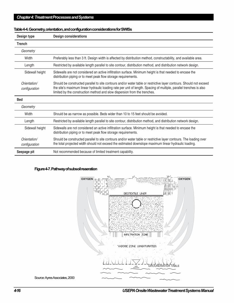
Width
Infiltration surface clogging and the resulting loss
of infiltrative capacity are less where the infiltra-
tion surface is narrow. This appears to occur
because reaeration of the soil below a narrow
infiltration surface is more rapid. The dominant
pathway for oxygen transport to the subsoil appears
to be diffusion through the soil surrounding the
infiltration surface (figure 4-7). The unsaturated
zone below a wide surface quickly becomes
anaerobic because the rates of oxygen diffusion are
too low to meet the oxygen demands of biota and
organics on the infiltration surface. (Otis, 1985;
Siegrist et al., 1986). Therefore, trenches perform
better than beds. Typical trench widths range from
1 to 4 feet. Narrower trenches are preferred, but
soil conditions and construction techniques might
limit how narrow a trench can be constructed. On
sloping sites, narrow trenches are a necessity
because in keeping the infiltration surface level, the
uphill side of the trench bottom might be excavated
into a less suitable soil horizon. Wider trench
infiltration surfaces have been successful in at-
grade systems and mounds probably because the
engineered fill material and elevation above the
natural grade promote better reaeration of the fill.
Factors of safety in infiltration surface sizing
Sizing of onsite wastewater systems for single-family homes is typically based on the estimated peak daily flow
and the “long term acceptance rate” of the soil for septic tank effluent. In most states, the design flow is based on
the number of bedrooms in the house. A daily flow of 150 gallons is commonly assumed for each bedroom. This
daily flow per bedroom assumes two people per bedroom that generate 75 gpd each. Bedrooms, rather than
current occupancy, are used for the basis of SWIS design because the number of occupants in the house can
change.
Using this typical estimating procedure, a three-bedroom home would have a design flow of 150 gpd/bedroom x 3
bedrooms or 450 gpd. However, the actual daily average flow could be much less. Based on the 1990 census, the
average home is occupied by 2.8 persons. Each person in the United States generates 45 to 70 gpd of domestic
wastewater. Assuming these averages, the average daily flow would be 125 to 195 gpd or 28 to 44 percent of the
design flow, respectively. Therefore, the design flow includes an implicit factor of safety of 2.3 to 3.6. Of course,
this factor of safety varies inversely with the home occupancy and water use.
Unfortunately, the factors of safety implicitly built into the flow estimates are seldom recognized. This is
particularly true in the case of the design hydraulic loading rates, which were derived from existing SWISs. In
most codes, the hydraulic loading rates for sand are about 1.0 to 1.25 gpd/ft2. Because these hydraulic loading
rates assume daily flows of 150 gpd per bedroom, they are overestimated by a factor of 2.3 to 3.6. Fortunately,
these two assumptions largely cancel each other out in residential applications, but the suggested hydraulic
loading rates often are used to size commercial systems and systems for schools and similar facilities, where the
ratios between design flows and actual daily flows are closer to 1.0. This situation, combined with a lack of useful
information on allowable organic loading rates, has resulted in failures, particularly for larger systems where
actual flow approximates design.
USEPA Onsite Wastewater Treatment Systems Manual 4-15
Chapter 4: Treatment Processes and Systems
However, infiltration bed surface widths of greater
than 10 feet are not recommended because oxygen
transfer and clogging problems can occur (Con-
verse and Tyler, 2000; Converse et al., 1990).
Length
The trench length is important where downslope
linear loadings are critical, ground water quality
impacts are a concern, or the potential for ground
water mounding exists. In many jurisdictions,
trench lengths have been limited to 100 feet. This
restriction appeared in early codes written for
gravity distribution systems and exists as an artifact
with little or no practical basis when pressure
distribution is used. Trench lengths longer than 100
feet might be necessary to minimize ground water
impacts and to permit proper wastewater drainage
from the site. Long trenches can be used to reduce
the linear loadings on a site by spreading the
Comparing hydraulic and organic mass loadings for a restaurant wastewater
Infiltration surface sizing traditionally has been based on the daily hydraulic load determined through experience
to be acceptable for the soil characteristics. This approach to sizing fails to account for changes in applied
wastewater strength. Since soil clogging has been shown to be dependent on applied wastewater strength, it
might be more appropriate to size infiltration surfaces based on organic mass loadings.
To illustrate the impact of the different sizing methods, sizing computations for a restaurant are compared. A
septic tank is used for pretreatment prior to application to the SWIS. The SWIS is to be constructed in a sandy
loam with a moderate, subangular blocky structure. The suggested hydraulic loading rate for domestic septic tank
effluent on this soil is 0.6 gpd/ft2 (table 4-3). The restaurant septic tank effluent has the following characteristics:
BOD5
800 mg/L
TSS 200 mg/L
Average daily flow 600 gpd
Infiltration area based on hydraulic loading:
Area = 600 gpd/0.6 gpd/ft2 = 1,000 ft2
Infiltration area based on organic loading:
At the design infiltration rate of 0.6 gpd/ft2 recommended for domestic septic tank effluent, the equivalent organic
loading is (assuming a septic tank BOD5 effluent concentration of 150 mg/L)
Organic Loading = 150 mg/L x 0.6 gpd/ft2 x (8.34 lb/mg/L x 10-6 gal)
= 7.5 x 10⁻⁴ lb BOD5/ft2-d
Assuming 7.5 x 10⁻⁴ lb BOD5/ft2-d as the design organic loading rate,
Area = (800 mg-BOD5/L x 600 gpd x 8.34 lbs/mg/L x 10-6 gal)
(7.5 x 10⁻⁴ lb BOD5/ft2-d)
= 4.0 lb BOD5/d = 5337 ft2 (a 540% increase)
(7.5 x 10⁻⁴ lb BOD5/ft2-d)
Impact of a 40% water use reduction on infiltration area sizing
Based on hydraulic loading,
Area = (1 – 0.4) x 600 gpd = 600 ft2
0.6 gpd/ft2
Based on organic loading (note the concentration of BOD5 increases with water conservation but the mass of
BOD5
discharged does not change),
Area = (800 mg-BOD5/L x 600 gpd) x (8.34 lb/mg/L x 10-6 gal)
[(1 – 0.4) x 600 gpd] x (7.5 x 10⁻⁴ lb BOD5/ft2-d)
= 4.0 lb BOD5/d = 5337 ft2 (an 890% increase)
(7.5 x 10⁻⁴ lb BOD5/ft2-d)
Chapter 4: Treatment Processes and Systems
4-16 USEPA Onsite Wastewater Treatment Systems Manual
Figure 4-7. Pathway of subsoil reaeration
Source: Ayres Associates, 2000
Table 4-4. Geometry, orientation, and configuration considerations for SWISs
USEPA Onsite Wastewater Treatment Systems Manual 4-17
Chapter 4: Treatment Processes and Systems
wastewater loading parallel to and farther along the
surface contour. With current distribution/dosing
technology, materials, and construction methods,
trench lengths need be limited only by what is
practical or feasible on a given site. Also, use of
standard trench lengths, e.g., X feet of trench/BR,
is discouraged because it restricts the design options
to optimize performance for a given site condition.
Height
The height of the sidewall is determined primarily
by the type of porous medium used in the system,
the depth of the medium needed to encase the
distribution piping, and/or storage requirements for
peak flows. Because the sidewall is not included as
an active infiltration surface in sizing the infiltra-
tion area, the height of the sidewall can be mini-
mized to keep the infiltration surface high in the
soil profile. A height of 6 inches is usually suffi-
cient for most porous aggregate applications. Use
of a gravelless system requires a separate analysis
to determine the height based on whether it is an
aggregate-free (empty chamber) design or one that
substitutes a lightweight aggregate for washed
gravel or crushed stone.
Orientation
Orientation of the infiltration surface(s) becomes
an important consideration on sloping sites, sites
with shallow soils over a restrictive horizon or
saturated zone, and small or irregularly shaped lots.
The long axes of trenches should be aligned
parallel to the ground surface contours to reduce
linear contour hydraulic loadings and ground water
mounding potential. In some cases, ground water
or restrictive horizon contours may differ from
surface contours because of surface grading or the
soil’s morphological history. Where this occurs,
consideration should be given to aligning the
trenches with the contours of the limiting condition
rather than those of the surface. Extending the
trenches perpendicular to the ground water gradient
reduces the mass loadings per unit area by creating
a “line” source rather than a “point” source along
the contour. However, the designer must recognize
that the depth of the trenches and the soil horizon
in which the infiltration surface is placed will vary
across the system. Any adverse impacts this might
have on system performance should be mitigated
through design adjustments.
Configuration
The spacing of multiple trenches constructed
parallel to one another is determined by the soil
characteristics and the method of construction. The
sidewall-to-sidewall spacing must be sufficient to
enable construction without damage to the adjacent
trenches. Only in very tight soils will normally
used spacings be inadequate because of high soil
wetness and capillary fringe effects, which can
limit oxygen transfer. It is important to note that
the sum of the hydraulic loadings to one or more
trenches or beds per each unit of contour length
(when projected downslope) must not exceed the
estimated maximum contour loading for the site.
Also, the finer (tighter) the soil, the greater the
trench spacing should be to provide sufficient
oxygen transfer. Quantitative data are lacking, but
Camp (1985) reported a lateral impact of more
than 2.0 meters in a clay soil.
Given the advantages of lightweight gravelless
systems in terms of potentially reduced damage to
the site’s hydraulic capacity, parallel trenches may
physically be placed closer together, but the
downslope hydraulic capacity of the site and the
natural oxygen diffusion capacity of the soil cannot
be exceeded.
4.4.7 Wastewater distribution onto theinfiltration surface
The method and pattern of wastewater distribution
in a subsurface infiltration system are important
design elements. Uniform distribution aids in
maintaining unsaturated flow below the infiltration
surface, which results in wastewater retention times
in the soil that are sufficiently long to effect
treatment and promote subsoil reaeration. Uniform
distribution design also results in more complete
utilization of the infiltration surface.
Gravity flow and dosing are the two most com-
monly used distribution methods. For each method,
various network designs are used (table 4-5).
Gravity flow is the most commonly used method
because it is simple and inexpensive. This method
discharges effluent from the septic tank or other
pretreatment tank directly to the infiltration surface
as incoming wastewater displaces it from the
tank(s). It is characterized by the term “trickle
flow” because the effluent is slowly discharged
over much of the day. Typically, tank discharges
Chapter 4: Treatment Processes and Systems
4-18 USEPA Onsite Wastewater Treatment Systems Manual
are too low to flow throughout the distribution
network. Thus, distribution is unequal and local-
ized overloading of the infiltration surface occurs
with concomitant poor treatment and soil clogging
(Bouma, 1975; McGauhey and Winneberger, 1964;
Otis, 1985; Robeck et al., 1964).
Dosing, on the other hand, accumulates the waste-
water effluent in a dose tank from which the water
is periodically discharged under pressure in “doses”
to the infiltration system by a pump or siphon. The
pretreated wastewater is allowed to accumulate in
the dose tank and is discharged when a predeter-
mined water level, water volume, or elapsed time is
reached. The dose volumes and discharge rates are
usually such that much of the distribution network
is filled, resulting in more uniform distribution
over the infiltration surface. Dosing outperforms
gravity-flow systems because distribution is more
uniform. In addition, the periods between doses
provide opportunities for the subsoil to drain and
reaerate before the next dose (Bouma et al., 1974;
Hargett et al., 1982; Otis et al., 1977). However,
which method is most appropriate depends on the
specific application.
Gravity flow
Gravity flow can be used where there is a sufficient
elevation difference between the outlet of the
pretreatment tank and the SWIS to allow flow to
and through the SWIS by gravity. Gravity flow
systems are simple and inexpensive to construct but
are the least efficient method of distribution.
Distribution is very uneven over the infiltration
surface, resulting in localized overloading (Con-
verse, 1974; McGauhey and Winneberger, 1964;
Otis et al., 1978; University of Wisconsin, 1978).
Until a biomat forms on the infiltration surface to
slow the rate of infiltration, the wastewater resi-
dence time in the soil might be too short to effect
good treatment. As the biomat continues to form on
the overloaded areas, the soil surface becomes
clogged, forcing wastewater effluent to flow
through the porous medium of the trench until it
reaches an unclogged infiltration surface. This
phenomenon, known as “progressive clogging,”
occurs until the entire infiltration surface is ponded
and the sidewalls become the more active infiltra-
tion surfaces. Without extended periods of little or
no flow to allow the surface to dry, hydraulic
failure becomes imminent. Although inefficient,
these systems can work well for seasonal homes
with intermittent use or for households with low
occupancies. Seasonal use of SWISs allows the
infiltration surface to dry and the biomat to oxi-
dize, which rejuvenates the infiltration capacity.
Low occupancies result in mass loadings of waste-
water constituents that are lower and less likely to
exceed the soil’s capacity to completely treat the
effluent.
Perforated pipe
Four-inch-diameter perforated plastic pipe is the
most commonly used distribution piping for
Table 4-5. Distribution methods and applications.
USEPA Onsite Wastewater Treatment Systems Manual 4-19
Chapter 4: Treatment Processes and Systems
gravity flow systems. The piping is generally
smooth-walled rigid polyvinyl chloride (PVC), or
flexible corrugated polyethylene (PE) or acryloni-
trile-butadiene-styrene (ABS). One or two rows of
holes or slots spaced 12 inches apart are cut into the
pipe wall. Typically, the piping is laid level in
gravel (figure 4-1) with the holes or slots at the
bottom (ASTM, undated). One distribution line is
used per trench. In bed systems, multiple lines are
installed 3 to 6 feet apart.
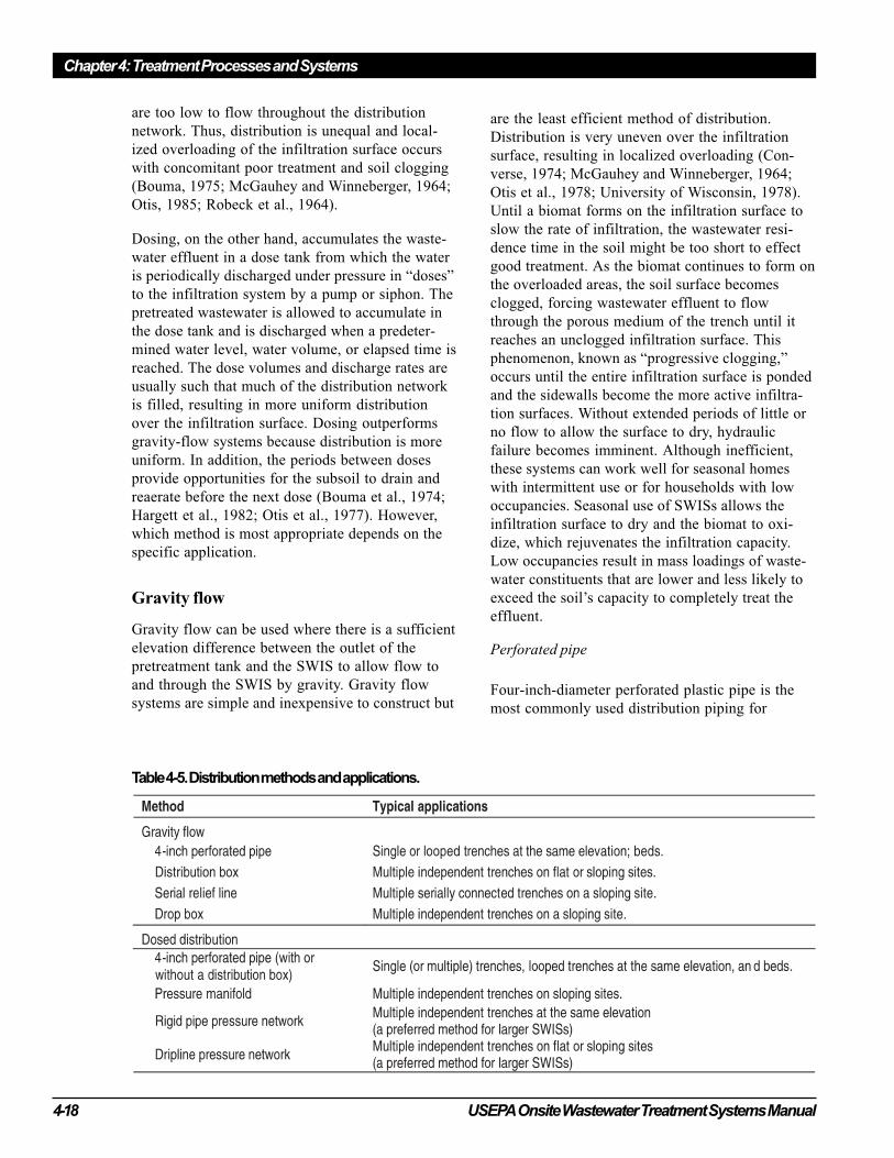
Distribution box
Distribution boxes are used to divide the wastewa-
ter effluent flow among multiple distribution lines.
They are shallow, flat bottomed, watertight struc-
tures with a single inlet and individual outlets
provided at the same elevation for each distribution
line. An above-grade cover allows access to the
inside of the box. The “d-box” must be laid level
on a sound, frost-proof footing to divide the flow
evenly among the outlets. Uneven settlement or
frost heaving results in unequal flow to the lateral
lines because the outlet hole elevations cease to be
level. If this occurs, adjustments must be made to
reestablish equal division of flow. Several devices
can be used. Adjustable weirs that can level the
outlet inverts and maintain the same length of weir
per outlet are one option. Other options include
designs that allow for leveling of the entire box
(figure 4-8). The box can also be used to take
individual trenches out of service by blocking the
outlet to the distribution lateral or raising the outlet
weir above the weir elevations for the other outlets.
Because of the inevitable movement of d-boxes,
their use has been discouraged for many years
(USPHS, 1957). However, under a managed care
system with regular adjustment, the d-box is
acceptable.
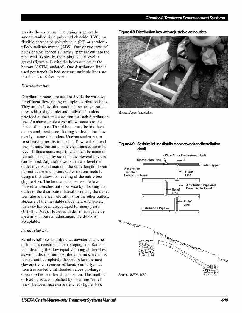
Serial relief line
Serial relief lines distribute wastewater to a series
of trenches constructed on a sloping site. Rather
than dividing the flow equally among all trenches
as with a distribution box, the uppermost trench is
loaded until completely flooded before the next
(lower) trench receives effluent. Similarly, that
trench is loaded until flooded before discharge
occurs to the next trench, and so on. This method
of loading is accomplished by installing “relief
lines” between successive trenches (figure 4-9).
Figure 4-8. Distribution box with adjustable weir outlets
Figure 4-9. Serial relief line distribution network and installation
detail
Source: USEPA, 1980.
Source: Ayres Associates.
Chapter 4: Treatment Processes and Systems
4-20 USEPA Onsite Wastewater Treatment Systems Manual
The relief lines are simple overflow lines that
connect one trench to the adjacent lower trench.
They are solid-wall pipes that connect the crown of
the upper trench distribution pipe with the distribu-
tion pipe in the lower trench. Successive relief lines
are separated by 5 to 10 feet to avoid short-
circuiting. This method of distribution makes full
hydraulic use of all bottom and sidewall infiltration
surfaces, creates the maximum hydrostatic head
over the infiltration surfaces to force the water into
the surrounding soil, and eliminates the problem of
dividing flows evenly among independent trenches.
However, because continuous ponding of the
infiltration surfaces is necessary for the system to
function, the trenches suffer hydraulic failure more
rapidly and progressively because the infiltration
surfaces cannot regenerate their infiltrative capacity.
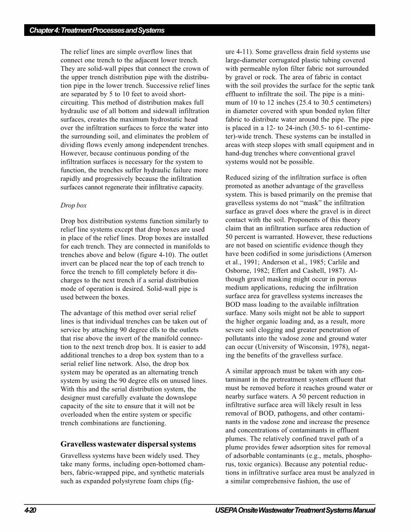
Drop box
Drop box distribution systems function similarly to
relief line systems except that drop boxes are used
in place of the relief lines. Drop boxes are installed
for each trench. They are connected in manifolds to
trenches above and below (figure 4-10). The outlet
invert can be placed near the top of each trench to
force the trench to fill completely before it dis-
charges to the next trench if a serial distribution
mode of operation is desired. Solid-wall pipe is
used between the boxes.
The advantage of this method over serial relief
lines is that individual trenches can be taken out of
service by attaching 90 degree ells to the outlets
that rise above the invert of the manifold connec-
tion to the next trench drop box. It is easier to add
additional trenches to a drop box system than to a
serial relief line network. Also, the drop box
system may be operated as an alternating trench
system by using the 90 degree ells on unused lines.
With this and the serial distribution system, the
designer must carefully evaluate the downslope
capacity of the site to ensure that it will not be
overloaded when the entire system or specific
trench combinations are functioning.
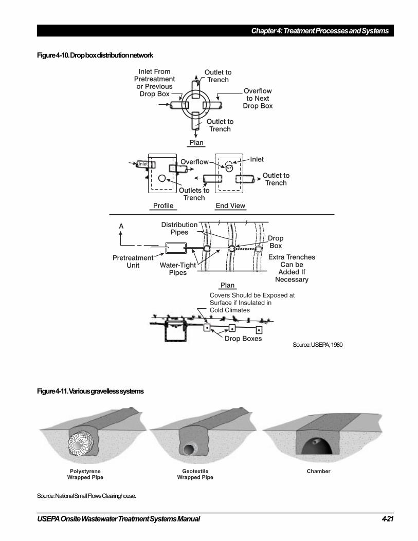
Gravelless wastewater dispersal systems
Gravelless systems have been widely used. They
take many forms, including open-bottomed cham-
bers, fabric-wrapped pipe, and synthetic materials
such as expanded polystyrene foam chips (fig-
ure 4-11). Some gravelless drain field systems use
large-diameter corrugated plastic tubing covered
with permeable nylon filter fabric not surrounded
by gravel or rock. The area of fabric in contact
with the soil provides the surface for the septic tank
effluent to infiltrate the soil. The pipe is a mini-
mum of 10 to 12 inches (25.4 to 30.5 centimeters)
in diameter covered with spun bonded nylon filter
fabric to distribute water around the pipe. The pipe
is placed in a 12- to 24-inch (30.5- to 61-centime-
ter)-wide trench. These systems can be installed in
areas with steep slopes with small equipment and in
hand-dug trenches where conventional gravel
systems would not be possible.
Reduced sizing of the infiltration surface is often
promoted as another advantage of the gravelless
system. This is based primarily on the premise that
gravelless systems do not “mask” the infiltration
surface as gravel does where the gravel is in direct
contact with the soil. Proponents of this theory
claim that an infiltration surface area reduction of
50 percent is warranted. However, these reductions
are not based on scientific evidence though they
have been codified in some jurisdictions (Amerson
et al., 1991; Anderson et al., 1985; Carlile and
Osborne, 1982; Effert and Cashell, 1987). Al-
though gravel masking might occur in porous
medium applications, reducing the infiltration
surface area for gravelless systems increases the
BOD mass loading to the available infiltration
surface. Many soils might not be able to support
the higher organic loading and, as a result, more
severe soil clogging and greater penetration of
pollutants into the vadose zone and ground water
can occur (University of Wisconsin, 1978), negat-
ing the benefits of the gravelless surface.
A similar approach must be taken with any con-
taminant in the pretreatment system effluent that
must be removed before it reaches ground water or
nearby surface waters. A 50 percent reduction in
infiltrative surface area will likely result in less
removal of BOD, pathogens, and other contami-
nants in the vadose zone and increase the presence
and concentrations of contaminants in effluent
plumes. The relatively confined travel path of a
plume provides fewer adsorption sites for removal
of adsorbable contaminants (e.g., metals, phospho-
rus, toxic organics). Because any potential reduc-
tions in infiltrative surface area must be analyzed in
a similar comprehensive fashion, the use of
USEPA Onsite Wastewater Treatment Systems Manual 4-21
Chapter 4: Treatment Processes and Systems
Figure 4-10. Drop box distribution network
Source: National Small Flows Clearinghouse.
Figure 4-11. Various gravelless systems
Source: USEPA, 1980
Chapter 4: Treatment Processes and Systems
4-22 USEPA Onsite Wastewater Treatment Systems Manual
gravelless medium should be treated similarly to
potential reductions from increased pretreatment
and better distribution and dosing concepts.
Despite the cautions stated above, the overall
inherent value of lightweight gravelless systems
should not be ignored, especially in areas where
gravel is expensive and at sites that have soils that
are susceptible to smearing or other structural
damage during construction due to the impacts of
heavy machinery on the site. In all applications
where gravel is used (see SWIS Media in the
following section), it must be properly graded and
washed. Improperly washed gravel can contribute
fines and other material that can plug voids in the
infiltrative surface and reduce hydraulic capability.
Gravel that is embedded into clay or fine soils
during placement can have the same effect.
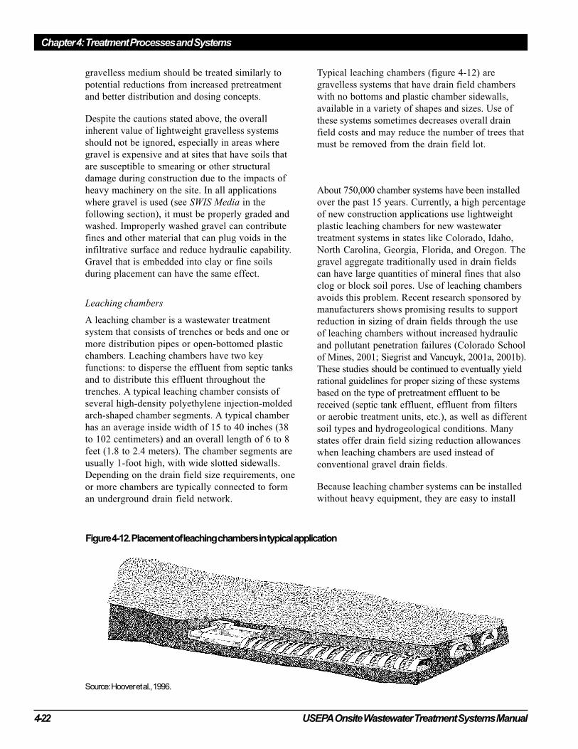
Leaching chambers
A leaching chamber is a wastewater treatment
system that consists of trenches or beds and one or
more distribution pipes or open-bottomed plastic
chambers. Leaching chambers have two key
functions: to disperse the effluent from septic tanks
and to distribute this effluent throughout the
trenches. A typical leaching chamber consists of
several high-density polyethylene injection-molded
arch-shaped chamber segments. A typical chamber
has an average inside width of 15 to 40 inches (38
to 102 centimeters) and an overall length of 6 to 8
feet (1.8 to 2.4 meters). The chamber segments are
usually 1-foot high, with wide slotted sidewalls.
Depending on the drain field size requirements, one
or more chambers are typically connected to form
an underground drain field network.
Typical leaching chambers (figure 4-12) are
gravelless systems that have drain field chambers
with no bottoms and plastic chamber sidewalls,
available in a variety of shapes and sizes. Use of
these systems sometimes decreases overall drain
field costs and may reduce the number of trees that
must be removed from the drain field lot.
About 750,000 chamber systems have been installed
over the past 15 years. Currently, a high percentage
of new construction applications use lightweight
plastic leaching chambers for new wastewater
treatment systems in states like Colorado, Idaho,
North Carolina, Georgia, Florida, and Oregon. The
gravel aggregate traditionally used in drain fields
can have large quantities of mineral fines that also
clog or block soil pores. Use of leaching chambers
avoids this problem. Recent research sponsored by
manufacturers shows promising results to support
reduction in sizing of drain fields through the use
of leaching chambers without increased hydraulic
and pollutant penetration failures (Colorado School
of Mines, 2001; Siegrist and Vancuyk, 2001a, 2001b).
These studies should be continued to eventually yield
rational guidelines for proper sizing of these systems
based on the type of pretreatment effluent to be
received (septic tank effluent, effluent from filters
or aerobic treatment units, etc.), as well as different
soil types and hydrogeological conditions. Many
states offer drain field sizing reduction allowances
when leaching chambers are used instead of
conventional gravel drain fields.
Because leaching chamber systems can be installed
without heavy equipment, they are easy to install
Figure 4-12. Placement of leaching chambers in typical application
Source: Hoover et al., 1996.
USEPA Onsite Wastewater Treatment Systems Manual 4-23
Chapter 4: Treatment Processes and Systems
and repair. These high-capacity, open-bottom drain
field systems can provide greater storage than
conventional gravel systems and can be used in
areas appropriate for gravel aggregate drain fields.
Leaching systems can operate independently and
require little day-to-day maintenance. Their
maintenance requirements are comparable to those
of aggregate trench systems.
The lightweight chamber segments available on the
market stack together compactly for efficient
transport. Some chambers interlock with ribs
without fasteners, cutting installation time by
more than 50 percent reused and conventional
gravel/pipe systems. Such systems can be reused
and relocated if the site owner decides to build
on another drain field site. A key disadvantage of
leaching chambers compared to gravel drain
fields is that they can be more expensive if a
low-cost source of gravel is readily available.
Porous media should be placed along the chamber
sidewall area to a minimum compacted height of
8 inches above the trench bottom. Additional backfill
is placed to a minimum compacted height of 6 to12
inches above the chamber, depending on the chamber
strength. Individual chamber trench bottoms should
be leveled in all directions and follow the contour of
the ground surface elevation without any dams or
other water stops. The manufacturer’s installation
instructions should be followed, and systems should
be installed by an authorized contractor.
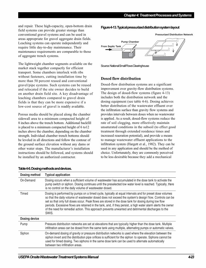
Dosed flow distribution
Dosed-flow distribution systems are a significant
improvement over gravity-flow distribution systems.
The design of dosed-flow systems (figure 4-13)
includes both the distribution network and the
dosing equipment (see table 4-6). Dosing achieves
better distribution of the wastewater effluent over
the infiltration surface than gravity flow systems and
provides intervals between doses when no wastewater
is applied. As a result, dosed-flow systems reduce the
rate of soil clogging, more effectively maintain
unsaturated conditions in the subsoil (to effect good
treatment through extended residence times and
increased reaeration potential), and provide a means
to manage wastewater effluent applications to the
infiltration system (Hargett et al., 1982). They can be
used in any application and should be the method of
choice. Unfortunately, they are commonly perceived
to be less desirable because they add a mechanical
Table 4-6. Dosing methods and devices.
Source: National Small Flows Clearinghouse
Figure 4-13. Typical pressurized distribution system layout
Chapter 4: Treatment Processes and Systems
4-24 USEPA Onsite Wastewater Treatment Systems Manual
component to an otherwise “passive” system and
add cost because of the dosing equipment. The
improved performance of dosed-flow systems over
gravity flow systems should outweigh these perceived
disadvantages, especially when a management
entity is in place. It must be noted, however, that if
dosed infiltration systems are allowed to pond, the
advantages of dosing are lost because the bottom
infiltration surface is continuously inundated and
no longer allowed to rest and reaerate. Therefore,
there is no value in using dosed-flow distribution in
SWISs designed to operate ponded, such as systems
that include sidewall area as an active infiltration
surface or those using serial relief lines.
Perforated pipe
Four-inch perforated pipe networks (with or
without d-boxes or pressure manifolds) that receive
dosed-flow applications are designed no differently
than gravity-flow systems. Many of the advantages
of dosing are lost in such networks, however,
because the distribution is only slightly better than
that of gravity-flow systems (Converse, 1974).
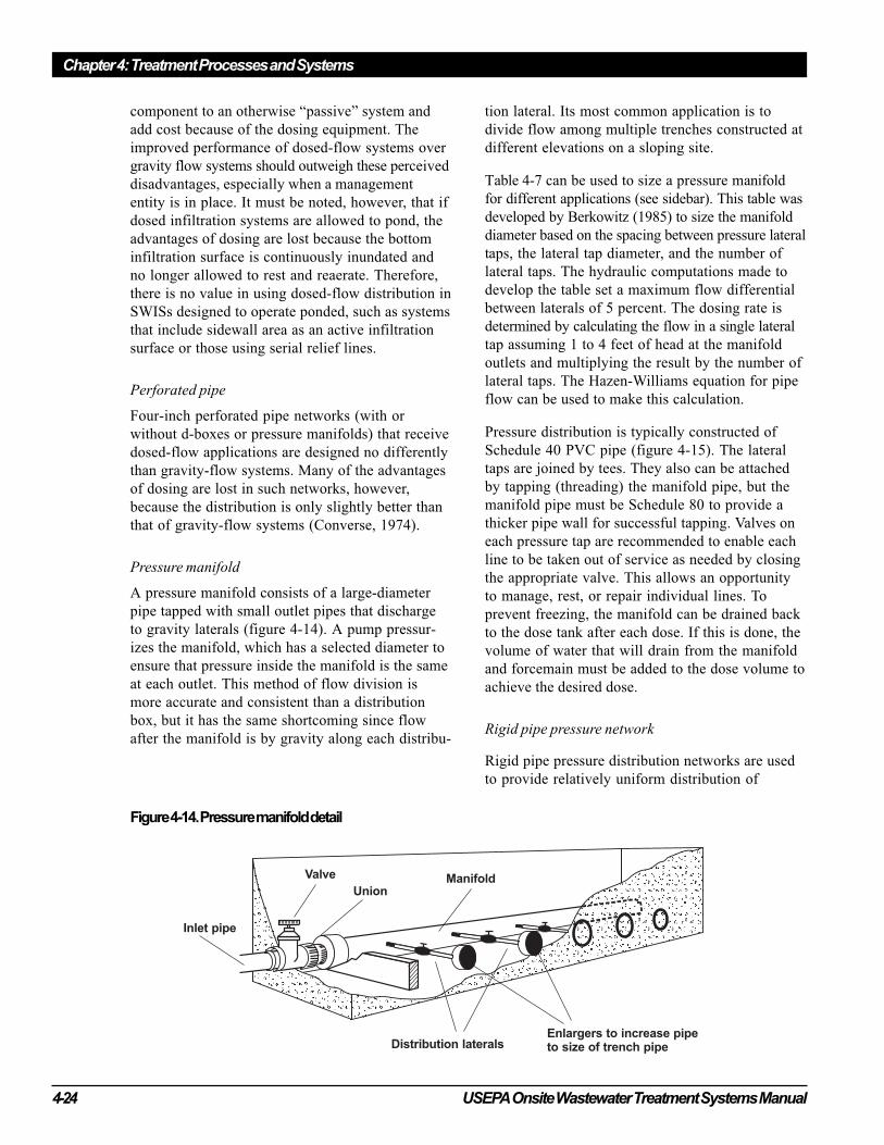
Pressure manifold
A pressure manifold consists of a large-diameter
pipe tapped with small outlet pipes that discharge
to gravity laterals (figure 4-14). A pump pressur-
izes the manifold, which has a selected diameter to
ensure that pressure inside the manifold is the same
at each outlet. This method of flow division is
more accurate and consistent than a distribution
box, but it has the same shortcoming since flow
after the manifold is by gravity along each distribu-
tion lateral. Its most common application is to
divide flow among multiple trenches constructed at
different elevations on a sloping site.
Table 4-7 can be used to size a pressure manifold
for different applications (see sidebar). This table was
developed by Berkowitz (1985) to size the manifold
diameter based on the spacing between pressure lateral
taps, the lateral tap diameter, and the number of
lateral taps. The hydraulic computations made to
develop the table set a maximum flow differential
between laterals of 5 percent. The dosing rate is
determined by calculating the flow in a single lateral
tap assuming 1 to 4 feet of head at the manifold
outlets and multiplying the result by the number of
lateral taps. The Hazen-Williams equation for pipe
flow can be used to make this calculation.
Pressure distribution is typically constructed of
Schedule 40 PVC pipe (figure 4-15). The lateral
taps are joined by tees. They also can be attached
by tapping (threading) the manifold pipe, but the
manifold pipe must be Schedule 80 to provide a
thicker pipe wall for successful tapping. Valves on
each pressure tap are recommended to enable each
line to be taken out of service as needed by closing
the appropriate valve. This allows an opportunity
to manage, rest, or repair individual lines. To
prevent freezing, the manifold can be drained back
to the dose tank after each dose. If this is done, the
volume of water that will drain from the manifold
and forcemain must be added to the dose volume to
achieve the desired dose.
Rigid pipe pressure network
Rigid pipe pressure distribution networks are used
to provide relatively uniform distribution of
Figure 4-14. Pressure manifold detail
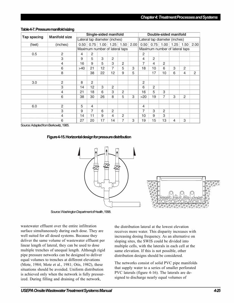
USEPA Onsite Wastewater Treatment Systems Manual 4-25
Chapter 4: Treatment Processes and Systems
Figure 4-15. Horizontal design for pressure distribution
Source: Washington Department of Health, 1998.
wastewater effluent over the entire infiltration
surface simultaneously during each dose. They are
well suited for all dosed systems. Because they
deliver the same volume of wastewater effluent per
linear length of lateral, they can be used to dose
multiple trenches of unequal length. Although rigid
pipe pressure networks can be designed to deliver
equal volumes to trenches at different elevations
(Mote, 1984; Mote et al., 1981; Otis, 1982), these
situations should be avoided. Uniform distribution
is achieved only when the network is fully pressur-
ized. During filling and draining of the network,
the distribution lateral at the lowest elevation
receives more water. This disparity increases with
increasing dosing frequency. As an alternative on
sloping sites, the SWIS could be divided into
multiple cells, with the laterals in each cell at the
same elevation. If this is not possible, other
distribution designs should be considered.
The networks consist of solid PVC pipe manifolds
that supply water to a series of smaller perforated
PVC laterals (figure 4-16). The laterals are de-
signed to discharge nearly equal volumes of
Table 4-7. Pressure manifold sizing
Source: Adapted from Berkowitz, 1985.
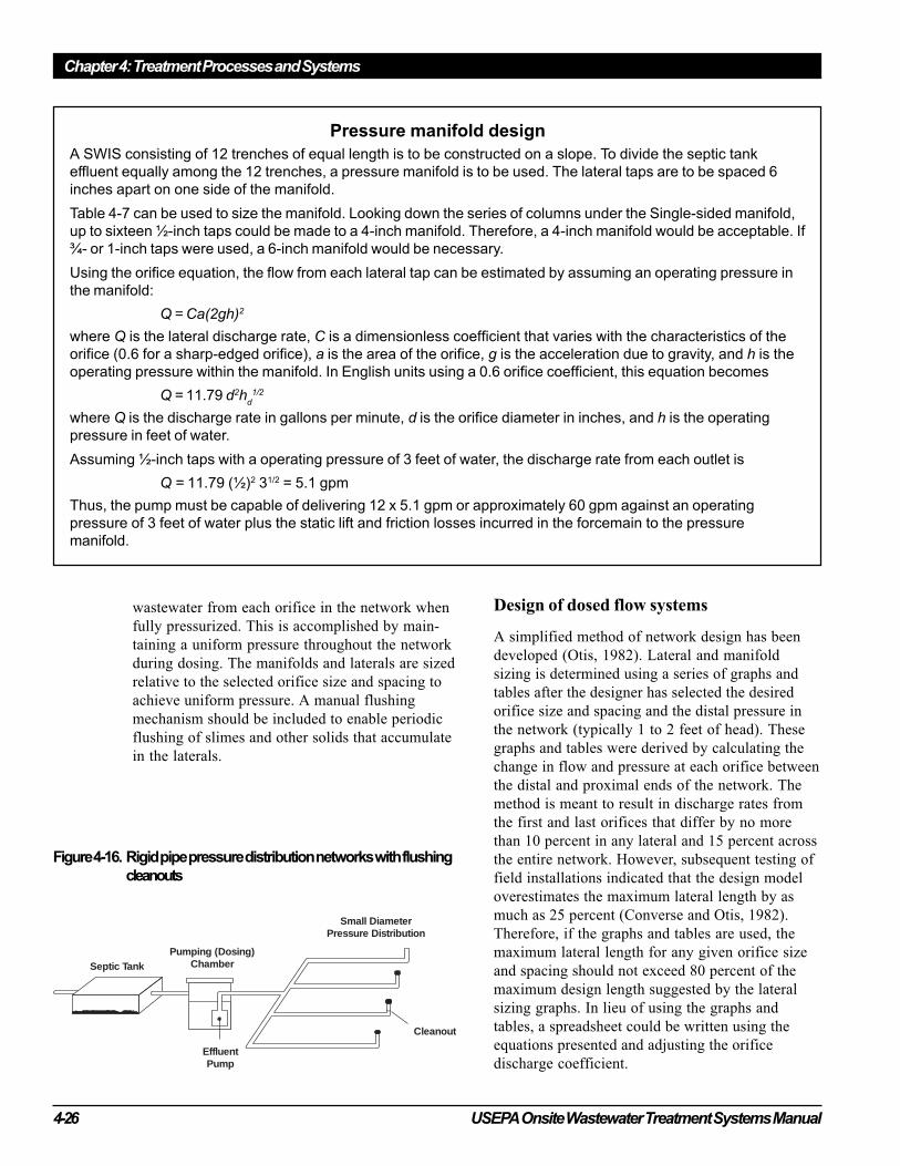
Chapter 4: Treatment Processes and Systems
4-26 USEPA Onsite Wastewater Treatment Systems Manual
wastewater from each orifice in the network when
fully pressurized. This is accomplished by main-
taining a uniform pressure throughout the network
during dosing. The manifolds and laterals are sized
relative to the selected orifice size and spacing to
achieve uniform pressure. A manual flushing
mechanism should be included to enable periodic
flushing of slimes and other solids that accumulate
in the laterals.
Design of dosed flow systems
A simplified method of network design has been
developed (Otis, 1982). Lateral and manifold
sizing is determined using a series of graphs and
tables after the designer has selected the desired
orifice size and spacing and the distal pressure in
the network (typically 1 to 2 feet of head). These
graphs and tables were derived by calculating the
change in flow and pressure at each orifice between
the distal and proximal ends of the network. The
method is meant to result in discharge rates from
the first and last orifices that differ by no more
than 10 percent in any lateral and 15 percent across
the entire network. However, subsequent testing of
field installations indicated that the design model
overestimates the maximum lateral length by as
much as 25 percent (Converse and Otis, 1982).
Therefore, if the graphs and tables are used, the
maximum lateral length for any given orifice size
and spacing should not exceed 80 percent of the
maximum design length suggested by the lateral
sizing graphs. In lieu of using the graphs and
tables, a spreadsheet could be written using the
equations presented and adjusting the orifice
discharge coefficient.
Pressure manifold design
A SWIS consisting of 12 trenches of equal length is to be constructed on a slope. To divide the septic tank
effluent equally among the 12 trenches, a pressure manifold is to be used. The lateral taps are to be spaced 6
inches apart on one side of the manifold.
Table 4-7 can be used to size the manifold. Looking down the series of columns under the Single-sided manifold,
up to sixteen ½-inch taps could be made to a 4-inch manifold. Therefore, a 4-inch manifold would be acceptable. If
¾- or 1-inch taps were used, a 6-inch manifold would be necessary.
Using the orifice equation, the flow from each lateral tap can be estimated by assuming an operating pressure in
the manifold:
Q = Ca(2gh)2
where Q is the lateral discharge rate, C is a dimensionless coefficient that varies with the characteristics of the
orifice (0.6 for a sharp-edged orifice), a is the area of the orifice, g is the acceleration due to gravity, and h is the
operating pressure within the manifold. In English units using a 0.6 orifice coefficient, this equation becomes
Q = 11.79 d2hd1/2
where Q is the discharge rate in gallons per minute, d is the orifice diameter in inches, and h is the operating
pressure in feet of water.
Assuming ½-inch taps with a operating pressure of 3 feet of water, the discharge rate from each outlet is
Q = 11.79 (½)2 31/2 = 5.1 gpm
Thus, the pump must be capable of delivering 12 x 5.1 gpm or approximately 60 gpm against an operating
pressure of 3 feet of water plus the static lift and friction losses incurred in the forcemain to the pressure
manifold.
Septic TankPumping (Dosing)
Chamber
EffluentPump
Small DiameterPressure Distribution
Cleanout
Figure 4-16. Rigid pipe pressure distribution networks with flushing
cleanouts
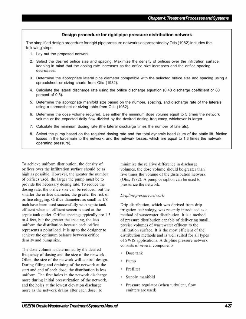
USEPA Onsite Wastewater Treatment Systems Manual 4-27
Chapter 4: Treatment Processes and Systems
To achieve uniform distribution, the density of
orifices over the infiltration surface should be as
high as possible. However, the greater the number
of orifices used, the larger the pump must be to
provide the necessary dosing rate. To reduce the
dosing rate, the orifice size can be reduced, but the
smaller the orifice diameter, the greater the risk of
orifice clogging. Orifice diameters as small as 1/8
inch have been used successfully with septic tank
effluent when an effluent screen is used at the
septic tank outlet. Orifice spacings typically are 1.5
to 4 feet, but the greater the spacing, the less
uniform the distribution because each orifice
represents a point load. It is up to the designer to
achieve the optimum balance between orifice
density and pump size.
The dose volume is determined by the desired
frequency of dosing and the size of the network.
Often, the size of the network will control design.
During filling and draining of the network at the
start and end of each dose, the distribution is less
uniform. The first holes in the network discharge
more during initial pressurization of the network,
and the holes at the lowest elevation discharge
more as the network drains after each dose. To
Design procedure for rigid pipe pressure distribution network
The simplified design procedure for rigid pipe pressure networks as presented by Otis (1982) includes the
following steps:
1. Lay out the proposed network.
2. Select the desired orifice size and spacing. Maximize the density of orifices over the infiltration surface,
keeping in mind that the dosing rate increases as the orifice size increases and the orifice spacing
decreases.
3. Determine the appropriate lateral pipe diameter compatible with the selected orifice size and spacing using a
spreadsheet or sizing charts from Otis (1982).
4. Calculate the lateral discharge rate using the orifice discharge equation (0.48 discharge coefficient or 80
percent of 0.6).
5. Determine the appropriate manifold size based on the number, spacing, and discharge rate of the laterals
using a spreadsheet or sizing table from Otis (1982).
6. Determine the dose volume required. Use either the minimum dose volume equal to 5 times the network
volume or the expected daily flow divided by the desired dosing frequency, whichever is larger.
7. Calculate the minimum dosing rate (the lateral discharge times the number of laterals).
8. Select the pump based on the required dosing rate and the total dynamic head (sum of the static lift, friction
losses in the forcemain to the network, and the network losses, which are equal to 1.3 times the network
operating pressure).
minimize the relative difference in discharge
volumes, the dose volume should be greater than
five times the volume of the distribution network
(Otis, 1982). A pump or siphon can be used to
pressurize the network.
Dripline pressure network
Drip distribution, which was derived from drip
irrigation technology, was recently introduced as a
method of wastewater distribution. It is a method
of pressure distribution capable of delivering small,
precise volumes of wastewater effluent to the
infiltration surface. It is the most efficient of the
distribution methods and is well suited for all types
of SWIS applications. A dripline pressure network
consists of several components:
• Dose tank
• Pump
• Prefilter
• Supply manifold
• Pressure regulator (when turbulent, flow
emitters are used)
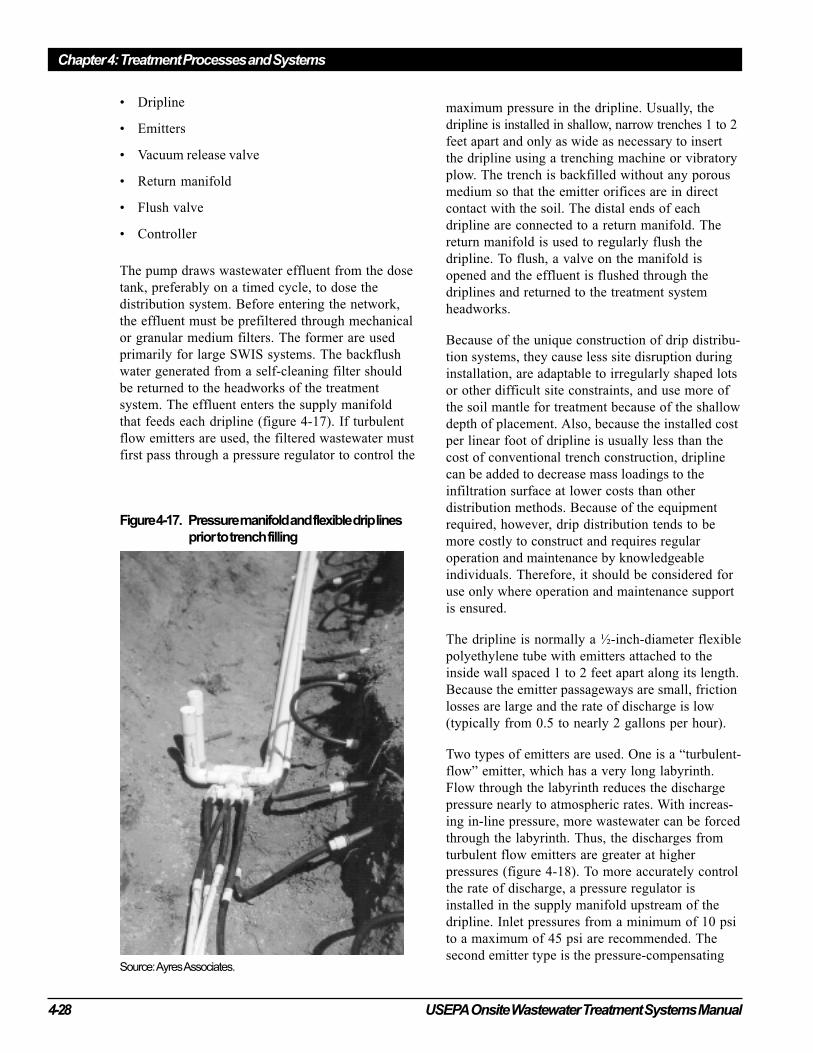
Chapter 4: Treatment Processes and Systems
4-28 USEPA Onsite Wastewater Treatment Systems Manual
• Dripline
• Emitters
• Vacuum release valve
• Return manifold
• Flush valve
• Controller
The pump draws wastewater effluent from the dose
tank, preferably on a timed cycle, to dose the
distribution system. Before entering the network,
the effluent must be prefiltered through mechanical
or granular medium filters. The former are used
primarily for large SWIS systems. The backflush
water generated from a self-cleaning filter should
be returned to the headworks of the treatment
system. The effluent enters the supply manifold
that feeds each dripline (figure 4-17). If turbulent
flow emitters are used, the filtered wastewater must
first pass through a pressure regulator to control the
maximum pressure in the dripline. Usually, the
dripline is installed in shallow, narrow trenches 1 to 2
feet apart and only as wide as necessary to insert
the dripline using a trenching machine or vibratory
plow. The trench is backfilled without any porous
medium so that the emitter orifices are in direct
contact with the soil. The distal ends of each
dripline are connected to a return manifold. The
return manifold is used to regularly flush the
dripline. To flush, a valve on the manifold is
opened and the effluent is flushed through the
driplines and returned to the treatment system
headworks.
Because of the unique construction of drip distribu-
tion systems, they cause less site disruption during
installation, are adaptable to irregularly shaped lots
or other difficult site constraints, and use more of
the soil mantle for treatment because of the shallow
depth of placement. Also, because the installed cost
per linear foot of dripline is usually less than the
cost of conventional trench construction, dripline
can be added to decrease mass loadings to the
infiltration surface at lower costs than other
distribution methods. Because of the equipment
required, however, drip distribution tends to be
more costly to construct and requires regular
operation and maintenance by knowledgeable
individuals. Therefore, it should be considered for
use only where operation and maintenance support
is ensured.
The dripline is normally a ½-inch-diameter flexible
polyethylene tube with emitters attached to the
inside wall spaced 1 to 2 feet apart along its length.
Because the emitter passageways are small, friction
losses are large and the rate of discharge is low
(typically from 0.5 to nearly 2 gallons per hour).
Two types of emitters are used. One is a “turbulent-
flow” emitter, which has a very long labyrinth.
Flow through the labyrinth reduces the discharge
pressure nearly to atmospheric rates. With increas-
ing in-line pressure, more wastewater can be forced
through the labyrinth. Thus, the discharges from
turbulent flow emitters are greater at higher
pressures (figure 4-18). To more accurately control
the rate of discharge, a pressure regulator is
installed in the supply manifold upstream of the
dripline. Inlet pressures from a minimum of 10 psi
to a maximum of 45 psi are recommended. The
second emitter type is the pressure-compensating
Figure 4-17. Pressure manifold and flexible drip lines
prior to trench filling
Source: Ayres Associates.
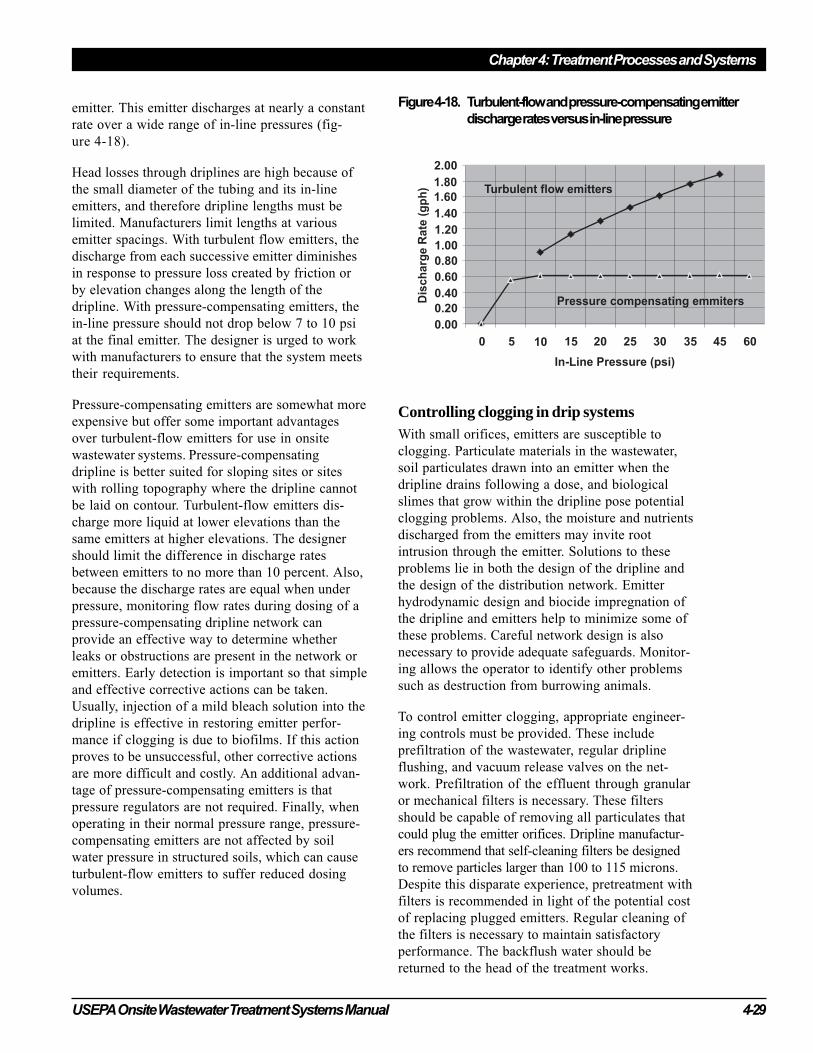
USEPA Onsite Wastewater Treatment Systems Manual 4-29
Chapter 4: Treatment Processes and Systems
emitter. This emitter discharges at nearly a constant
rate over a wide range of in-line pressures (fig-
ure 4-18).
Head losses through driplines are high because of
the small diameter of the tubing and its in-line
emitters, and therefore dripline lengths must be
limited. Manufacturers limit lengths at various
emitter spacings. With turbulent flow emitters, the
discharge from each successive emitter diminishes
in response to pressure loss created by friction or
by elevation changes along the length of the
dripline. With pressure-compensating emitters, the
in-line pressure should not drop below 7 to 10 psi
at the final emitter. The designer is urged to work
with manufacturers to ensure that the system meets
their requirements.
Pressure-compensating emitters are somewhat more
expensive but offer some important advantages
over turbulent-flow emitters for use in onsite
wastewater systems. Pressure-compensating
dripline is better suited for sloping sites or sites
with rolling topography where the dripline cannot
be laid on contour. Turbulent-flow emitters dis-
charge more liquid at lower elevations than the
same emitters at higher elevations. The designer
should limit the difference in discharge rates
between emitters to no more than 10 percent. Also,
because the discharge rates are equal when under
pressure, monitoring flow rates during dosing of a
pressure-compensating dripline network can
provide an effective way to determine whether
leaks or obstructions are present in the network or
emitters. Early detection is important so that simple
and effective corrective actions can be taken.
Usually, injection of a mild bleach solution into the
dripline is effective in restoring emitter perfor-
mance if clogging is due to biofilms. If this action
proves to be unsuccessful, other corrective actions
are more difficult and costly. An additional advan-
tage of pressure-compensating emitters is that
pressure regulators are not required. Finally, when
operating in their normal pressure range, pressure-
compensating emitters are not affected by soil
water pressure in structured soils, which can cause
turbulent-flow emitters to suffer reduced dosing
volumes.
Controlling clogging in drip systemsWith small orifices, emitters are susceptible to
clogging. Particulate materials in the wastewater,
soil particulates drawn into an emitter when the
dripline drains following a dose, and biological
slimes that grow within the dripline pose potential
clogging problems. Also, the moisture and nutrients
discharged from the emitters may invite root
intrusion through the emitter. Solutions to these
problems lie in both the design of the dripline and
the design of the distribution network. Emitter
hydrodynamic design and biocide impregnation of
the dripline and emitters help to minimize some of
these problems. Careful network design is also
necessary to provide adequate safeguards. Monitor-
ing allows the operator to identify other problems
such as destruction from burrowing animals.
To control emitter clogging, appropriate engineer-
ing controls must be provided. These include
prefiltration of the wastewater, regular dripline
flushing, and vacuum release valves on the net-
work. Prefiltration of the effluent through granular
or mechanical filters is necessary. These filters
should be capable of removing all particulates that
could plug the emitter orifices. Dripline manufactur-
ers recommend that self-cleaning filters be designed
to remove particles larger than 100 to 115 microns.
Despite this disparate experience, pretreatment with
filters is recommended in light of the potential cost
of replacing plugged emitters. Regular cleaning of
the filters is necessary to maintain satisfactory
performance. The backflush water should be
returned to the head of the treatment works.
Figure 4-18. Turbulent-flow and pressure-compensating emitter
discharge rates versus in-line pressure
Chapter 4: Treatment Processes and Systems
4-30 USEPA Onsite Wastewater Treatment Systems Manual
The dripline must be flushed on a regular schedule
to keep it scoured of solids. Flushing is accom-
plished by opening the flush valve on the return
manifold and increasing the pumping rate to
achieve scouring velocity. Each supplier recom-
mends a velocity and procedure for this process.
The flushing rate and volume must include water
losses (discharge) through the emitters during the
flushing event. Both continuous flushing and timed
flushing are used. However, flushing can add a
significant hydraulic load to the treatment system
and must be considered in the design. If intermit-
tent flushing is practiced, flushing should be
performed at least monthly.
Aspiration of soil particles is another potential
emitter clogging hazard. Draining of the network
following a dosing cycle can create a vacuum in the
network. The vacuum can cause soil particles to be
aspirated into the emitter orifices. To prevent this
from occurring, vacuum relief valves are used. It is
best to install these at the high points of both the
supply and return manifolds.
Placement and layout of drip systems
When drip distribution was introduced, the ap-
proach to sizing SWISs using this distribution
method was substantially different from that for
SWISs using other distribution methods. Manufac-
turer-recommended hydraulic loading rates were
expressed in terms of gallons per day per square
foot of drip distribution footprint area. Typically,
the recommended rates were based on 2-foot
emitter and dripline spacing. Therefore, each
emitter would serve 4 square feet of footprint area.
Because the dripline is commonly plowed into the
soil without surrounding it with porous medium,
the soil around the dripline becomes the actual
infiltration surface. The amount of infiltration
surface provided is approximately 2/3 to 1 square
foot per 5 linear feet of dripline. As a result, the
wastewater loading rate is considerably greater than
the hydraulic loadings recommended for traditional
SWISs. Experience has shown however, that the
hydraulic loading on this surface can be as much as
seven times higher than that of traditional SWIS
designs (Ayres Associates, 1994). This is probably
due to the very narrow geometry, higher levels of
pretreatment, shallow placement, and intermittent
loadings of the trenches, all of which help to
enhance reaeration of the infiltration surface.
The designer must be aware of the differences
between the recommended hydraulic loadings for
drip distribution and those customarily used for
traditional SWISs. The recommended drip distribu-
tion loadings are a function of the soil, dripline
spacing, and applied effluent quality. It is necessary
to express the hydraulic loading in terms of the
footprint area because the individual dripline trenches
are not isolated infiltration surfaces. If the emitter
and/or dripline spacing is reduced, the wetting
fronts emanating from each emitter could overlap
and significantly reduce hydraulic performance. There-
fore, reducing the emitter and/or dripline spacing should
not reduce the overall required system footprint.
Reducing the spacing might be beneficial for irrigat-
ing small areas of turf grass, but the maximum daily
emitter discharge must be reduced proportionately by
adding more dripline to maintain the same footprint
size. Using higher hydraulic loading rates must be
carefully considered in light of secondary boundary
loadings, which could result in excessive ground
water mounding (see chapter 5). Further, the instanta-
neous hydraulic loading during a dose must be
controlled because storage is not provided in the
dripline trench. If the dose volume is too high, the
wastewater can erupt at the ground surface.
Layout of the drip distribution network must be
considered carefully. Two important consequences
of the network layout are the impacts on dose
pump sizing necessary to achieve adequate flushing
flows and the extent of localized overloading due
to internal dripline drainage. Flushing flow rates
are a function of the number of manifold/dripline
connections: More connections create a need for
greater flushing flows, which require a larger
pump. To minimize the flushing flow rate, the
length of each dripline should be made as long as
possible in accordance with the manufacturer’s
recommendations. To fit the landscape, the dripline
can be looped between the supply and return
manifolds (figure 4-19). Consideration should also
be given to dividing the network into more than
one cell to reduce the number of connections in an
individual network. A computer program has been
developed to evaluate and optimize the hydraulic
design for adequate flushing flows of dripline
networks that use pressure-compensating emitters
(Berkowitz and Harman, 1994).
Internal drainage that occurs following each dose
or when the soils around the dripline are saturated

USEPA Onsite Wastewater Treatment Systems Manual 4-31
Chapter 4: Treatment Processes and Systems
can cause significant hydraulic overloading to
lower portions of the SWIS. Following a dose
cycle, the dripline drains through the emitters. On
sloping sites, the upper driplines drain to the lower
driplines, where hydraulic overloading can occur.
Any free water around the dripline can enter
through an emitter and drain to the lowest eleva-
tion. Each of these events needs to be avoided as
much as possible through design. The designer can
minimize internal drainage problems by isolating
the driplines from each other in a cell, by aligning
the supply and return manifolds with the site’s
contours. A further safeguard is to limit the number
of doses per day while keeping the instantaneous
hydraulic loadings to a minimum so the dripline
trench is not flooded following a dose. This trade-
off is best addressed by determining the maximum
hydraulic loading and adjusting the number of
doses to fit this dosing volume.
Freezing of dripline networks has occurred in
severe winter climates. Limited experience indicates
that shallow burial depths together with a lack of
uncompacted snow cover or other insulating
materials might lead to freezing. In severe winter
climates, the burial depth of dripline should be
increased appropriately and a good turf grass
established over the network. Mulching the area the
winter after construction or every winter should be
considered. Also, it is good practice to install the
vacuum release valves below grade and insulate the
air space around them. Although experience with
drip distribution in cold climates is limited, these
safeguards should provide adequate protection.
Dosing methods
Two methods of dosing have been used (table 4-6).
With on-demand dosing, the wastewater effluent
rises to a preset level in the dose tank and the pump
or siphon is activated by a float switch or other
mechanism to initiate discharge (figure 4-20).
During peak-flow periods, dosing is frequent with
little time between doses for the infiltration system
to drain and the subsoil to reaerate. During low-
flow periods, dosing intervals are long, which can
be beneficial in controlling biomat development
but is inefficient in using the hydraulic capacity of
the system.
Figure 4-19. Dripline layout on a site with trees
Source: Adapted from American Manufacturing, 2001.
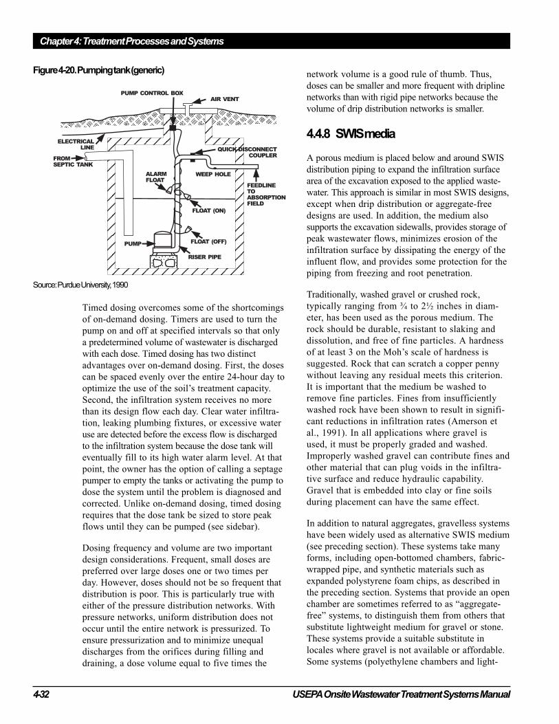
Chapter 4: Treatment Processes and Systems
4-32 USEPA Onsite Wastewater Treatment Systems Manual
Timed dosing overcomes some of the shortcomings
of on-demand dosing. Timers are used to turn the
pump on and off at specified intervals so that only
a predetermined volume of wastewater is discharged
with each dose. Timed dosing has two distinct
advantages over on-demand dosing. First, the doses
can be spaced evenly over the entire 24-hour day to
optimize the use of the soil’s treatment capacity.
Second, the infiltration system receives no more
than its design flow each day. Clear water infiltra-
tion, leaking plumbing fixtures, or excessive water
use are detected before the excess flow is discharged
to the infiltration system because the dose tank will
eventually fill to its high water alarm level. At that
point, the owner has the option of calling a septage
pumper to empty the tanks or activating the pump to
dose the system until the problem is diagnosed and
corrected. Unlike on-demand dosing, timed dosing
requires that the dose tank be sized to store peak
flows until they can be pumped (see sidebar).
Dosing frequency and volume are two important
design considerations. Frequent, small doses are
preferred over large doses one or two times per
day. However, doses should not be so frequent that
distribution is poor. This is particularly true with
either of the pressure distribution networks. With
pressure networks, uniform distribution does not
occur until the entire network is pressurized. To
ensure pressurization and to minimize unequal
discharges from the orifices during filling and
draining, a dose volume equal to five times the
network volume is a good rule of thumb. Thus,
doses can be smaller and more frequent with dripline
networks than with rigid pipe networks because the
volume of drip distribution networks is smaller.
4.4.8 SWIS media
A porous medium is placed below and around SWIS
distribution piping to expand the infiltration surface
area of the excavation exposed to the applied waste-
water. This approach is similar in most SWIS designs,
except when drip distribution or aggregate-free
designs are used. In addition, the medium also
supports the excavation sidewalls, provides storage of
peak wastewater flows, minimizes erosion of the
infiltration surface by dissipating the energy of the
influent flow, and provides some protection for the
piping from freezing and root penetration.
Traditionally, washed gravel or crushed rock,
typically ranging from ¾ to 2½ inches in diam-
eter, has been used as the porous medium. The
rock should be durable, resistant to slaking and
dissolution, and free of fine particles. A hardness
of at least 3 on the Moh’s scale of hardness is
suggested. Rock that can scratch a copper penny
without leaving any residual meets this criterion.
It is important that the medium be washed to
remove fine particles. Fines from insufficiently
washed rock have been shown to result in signifi-
cant reductions in infiltration rates (Amerson et
al., 1991). In all applications where gravel is
used, it must be properly graded and washed.
Improperly washed gravel can contribute fines and
other material that can plug voids in the infiltra-
tive surface and reduce hydraulic capability.
Gravel that is embedded into clay or fine soils
during placement can have the same effect.
In addition to natural aggregates, gravelless systems
have been widely used as alternative SWIS medium
(see preceding section). These systems take many
forms, including open-bottomed chambers, fabric-
wrapped pipe, and synthetic materials such as
expanded polystyrene foam chips, as described in
the preceding section. Systems that provide an open
chamber are sometimes referred to as “aggregate-
free” systems, to distinguish them from others that
substitute lightweight medium for gravel or stone.
These systems provide a suitable substitute in
locales where gravel is not available or affordable.
Some systems (polyethylene chambers and light-
Figure 4-20. Pumping tank (generic)
Source: Purdue University, 1990
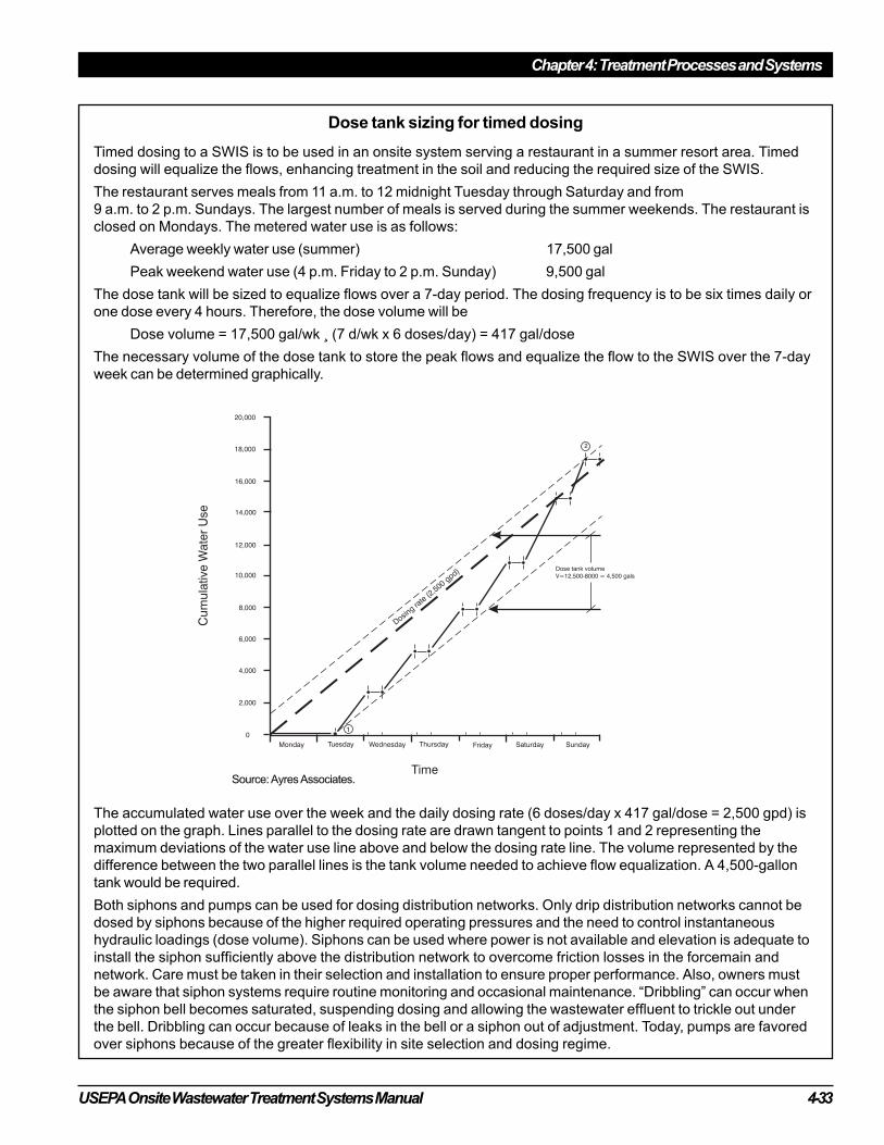
USEPA Onsite Wastewater Treatment Systems Manual 4-33
Chapter 4: Treatment Processes and Systems
Dose tank sizing for timed dosing
Timed dosing to a SWIS is to be used in an onsite system serving a restaurant in a summer resort area. Timed
dosing will equalize the flows, enhancing treatment in the soil and reducing the required size of the SWIS.
The restaurant serves meals from 11 a.m. to 12 midnight Tuesday through Saturday and from
9 a.m. to 2 p.m. Sundays. The largest number of meals is served during the summer weekends. The restaurant is
closed on Mondays. The metered water use is as follows:
Average weekly water use (summer) 17,500 gal
Peak weekend water use (4 p.m. Friday to 2 p.m. Sunday) 9,500 gal
The dose tank will be sized to equalize flows over a 7-day period. The dosing frequency is to be six times daily or
one dose every 4 hours. Therefore, the dose volume will be
Dose volume = 17,500 gal/wk ¸ (7 d/wk x 6 doses/day) = 417 gal/dose
The necessary volume of the dose tank to store the peak flows and equalize the flow to the SWIS over the 7-day
week can be determined graphically.
The accumulated water use over the week and the daily dosing rate (6 doses/day x 417 gal/dose = 2,500 gpd) is
plotted on the graph. Lines parallel to the dosing rate are drawn tangent to points 1 and 2 representing the
maximum deviations of the water use line above and below the dosing rate line. The volume represented by the
difference between the two parallel lines is the tank volume needed to achieve flow equalization. A 4,500-gallon
tank would be required.
Both siphons and pumps can be used for dosing distribution networks. Only drip distribution networks cannot be
dosed by siphons because of the higher required operating pressures and the need to control instantaneous
hydraulic loadings (dose volume). Siphons can be used where power is not available and elevation is adequate to
install the siphon sufficiently above the distribution network to overcome friction losses in the forcemain and
network. Care must be taken in their selection and installation to ensure proper performance. Also, owners must
be aware that siphon systems require routine monitoring and occasional maintenance. “Dribbling” can occur when
the siphon bell becomes saturated, suspending dosing and allowing the wastewater effluent to trickle out under
the bell. Dribbling can occur because of leaks in the bell or a siphon out of adjustment. Today, pumps are favored
over siphons because of the greater flexibility in site selection and dosing regime.
Source: Ayres Associates.
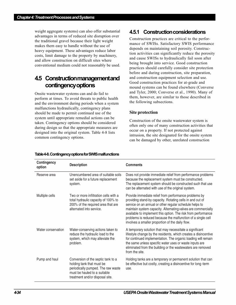
Chapter 4: Treatment Processes and Systems
4-34 USEPA Onsite Wastewater Treatment Systems Manual
weight aggregate systems) can also offer substantial
advantages in terms of reduced site disruption over
the traditional gravel because their light weight
makes them easy to handle without the use of
heavy equipment. These advantages reduce labor
costs, limit damage to the property by machinery,
and allow construction on difficult sites where
conventional medium could not reasonably be used.
4.5 Construction management andcontingency options
Onsite wastewater systems can and do fail to
perform at times. To avoid threats to public health
and the environment during periods when a system
malfunctions hydraulically, contingency plans
should be made to permit continued use of the
system until appropriate remedial actions can be
taken. Contingency options should be considered
during design so that the appropriate measures are
designed into the original system. Table 4-8 lists
common contingency options.
4.5.1 Construction considerationsConstruction practices are critical to the perfor-
mance of SWISs. Satisfactory SWIS performance
depends on maintaining soil porosity. Construc-
tion activities can significantly reduce the porosity
and cause SWISs to hydraulically fail soon after
being brought into service. Good construction
practices should carefully consider site protection
before and during construction, site preparation,
and construction equipment selection and use.
Good construction practices for at-grade and
mound systems can be found elsewhere (Converse
and Tyler, 2000; Converse et al., 1990). Many of
them, however, are similar to those described in
the following subsections.
Site protection
Construction of the onsite wastewater system is
often only one of many construction activities that
occur on a property. If not protected against
intrusion, the site designated for the onsite system
can be damaged by other, unrelated construction
Table 4-8. Contingency options for SWIS malfunctions
USEPA Onsite Wastewater Treatment Systems Manual 4-35
Chapter 4: Treatment Processes and Systems
activities. Therefore, the site should be staked and
roped off before any construction activities begin
to make others aware of the site and to keep traffic
and materials stockpiles off the site.
The designer should anticipate what activities will
be necessary during construction and designate
acceptable areas for them to occur. Site access
points and areas for traffic lanes, material stockpil-
ing, and equipment parking should be designated
on the drawings for the contractor.
Site preparation
Site preparation activities include clearing and
surface preparation for filling. Before these activi-
ties are begun, the soil moisture should be deter-
mined. In nongranular soils, compaction will occur
if the soil is near its plastic limit. This can be tested
by removing a sample of soil and rolling it between
the palms of the hands. If the soil fails to form a
“rope” the soil is sufficiently dry to proceed.
However, constant care should be taken to avoid
soil disturbance as much as possible.
Clearing
Clearing should be limited to mowing and raking
because the surface should be only minimally
disturbed. If trees must be removed, they should be
cut at the base of the trunk and removed without
heavy machinery. If it is necessary to remove the
stumps, they should be ground out. Grubbing of
the site (mechanically raking away roots) should be
avoided. If the site is to be filled, the surface
should be moldboard- or chisel-plowed parallel to
the contour (usually to a depth of 7 to 10 inches)
when the soil is sufficiently dry to ensure maxi-
mum vertical permeability. The organic layer
should not be removed. Scarifying the surface with
the teeth of a backhoe bucket is not sufficient.
Excavation
Excavation activities can cause significant reduc-
tions in soil porosity and permeability (Tyler et al.,
1985). Compaction and smearing of the soil
infiltrative surface occur from equipment traffic
and vibration, scraping actions of the equipment, and
placement of the SWIS medium on the infiltration
surface. Lightweight backhoes are most commonly
used. Front-end loaders and blades should not be used
because of their scraping action. All efforts should
be made to avoid any disturbance to the exposed
infiltration surface. Equipment should be kept off
the infiltration field. Before the SWIS medium is
installed, any smeared areas should be scarified and
the surface gently raked. If gravel or crushed rock
is to be used for SWIS medium, the rock should be
placed in the trench by using the backhoe bucket
rather than dumping it directly from the truck. If
damage occurs, it might be possible to restore the
area, but only by removing the compacted layer. It
might be necessary to remove as much as 4 inches
of soil to regain the natural soil porosity and
permeability (Tyler et al., 1985). Consequences of
the removal of this amount of soil over the entire
infiltration surface can be significant. It will reduce
the separation distance to the restrictive horizon
and could place the infiltration surface in an
unacceptable soil horizon.
To avoid potential soil damage during construction,
the soil below the proposed infiltration surface
elevation must be below its plastic limit. This
should be tested before excavation begins. Also,
excavation should be scheduled only when the
infiltration surface can be covered the same day to
avoid loss of permeability from wind-blown silt or
raindrop impact. Another solution is to use light-
weight gravelless systems, which reduce the
damage and speed the construction process.
Before leaving the site, the area around the site
should be graded to divert surface runoff from the
SWIS area. The backfill over the infiltration
surface should be mounded slightly to account for
settling and eliminate depressions over the system
that can pond water. Finally, the area should be
seeded and mulched.
4.5.2 Operation, maintenance, andmonitoring
Subsurface wastewater infiltration systems require
little operator intervention. Table 4-9 lists typical
operation, maintenance, and monitoring activities
that should be performed. However, more complex
pretreatment, larger and more variable flows, and
higher-risk installations increase the need for
maintenance and monitoring. More information is
provided in the USEPA draft Guidelines for Onsite/
Decentralized Wastewater Systems (2000) and in the
chapter 4 fact sheets.

Chapter 4: Treatment Processes and Systems
4-36 USEPA Onsite Wastewater Treatment Systems Manual
4.5.3 Considerations for large andcommercial systems
Designs for systems treating larger flows follow the
same guidelines used for residential systems, but they
must address characteristics of the wastewater to be
treated, site characteristics, infiltration surface sizing,
and contingency planning more comprehensively.
Wastewater characteristics
Wastewaters from cluster systems serving multiple
homes or commercial establishments can differ
substantially in flow pattern and waste strength from
wastewaters generated by single family residences.
The ratio of peak to average daily flow from residen-
tial clusters is typically much lower than what is
typical from single residences. This is because the
moderating effect associated with combining multiple
water use patterns reduces the daily variation in flow.
Commercial systems, on the other hand, can vary
significantly in wastewater strength. Typically,
restaurants have high concentrations of grease and
BOD, laundromats have high sodium and suspended
solids concentrations, and toilet facilities at parks
and rest areas have higher concentrations of BOD,
TSS, and nitrogen. These differences in daily flow
patterns and waste strengths must be dealt with in
the design of SWISs. Therefore, it is important to
characterize the wastewater fully before initiating
design (see chapter 3).
Site characteristics
The proposed site for a SWIS that will treat waste-
water from a cluster of homes or a commercial
establishment must be evaluated more rigorously
than a single-residence site because of the larger
volume of water that is to be applied and the
greater need to determine hydraulic gradients and
direction. SWIS discharges can be from 10 to more
than 100 times the amount of water that the soil
infiltration surface typically receives from precipi-
tation. For example, assume that an area receives an
average of 40 inches of rainfall per year. Of that, less
than 25 percent (about 10 inches annually) infiltrates
and even less percolates to the water table. A waste-
water infiltration system is designed to infiltrate
0.4 to 1.6 inches per day, or 146 to 584 inches per
year. Assuming actual system flows are 30 percent
of design flows, this is reduced to 44 to 175 inches
per year even under this conservative approach.
The soils associated with small systems can usually
accommodate these additional flows. However,
systems that treat larger flows load wastewaters to
the soil over a greater area and might exceed the
site’s capacity to accept the wastewater. Restrictive
horizons that may inhibit deep percolation need to
Table 4-9. Operation, maintenance, and monitoring activities
USEPA Onsite Wastewater Treatment Systems Manual 4-37
Chapter 4: Treatment Processes and Systems
be identified before design. Ground water mounding
analysis should be performed to determine whether
the hydraulic loading to the saturated zone (second-
ary design boundary), rather than the loading to the
infiltration surface, controls system sizing (see Chap-
ter 5). If the secondary boundary controls design, the
size of the infiltration surface, its geometry, and even
how wastewater is applied will be affected.
Infiltration surface sizing
Selection of the design flow is a very important
consideration in infiltration surface sizing. State
codified design flows for residential systems
typically are 2 to 5 times greater than the average
daily flow actually generated in the home. This
occurs because the design flow is usually based on
the number of bedrooms rather than the number of
occupants. As a result, the actual daily flow is often
a small fraction of the design flow.
This is not the case when the per capita flows for
the population served or metered flows are used as
the design flow. In such instances, the ratio of
design flow to actual daily flow can approach
unity. This is because the same factors of safety are
typically not used to determine the design flow. In
itself, this is not a problem. The problem arises
when the metered or averaged hydraulic loading
rates are used to size the infiltration surface. These
rates can be more than two times what the soil
below the undersized system is actually able to
accept. As a result, SWISs would be significantly
undersized. This problem is exacerbated where the
waste strength is high.
To avoid the problem of undersizing the infiltration
surface, designs must compensate in some way.
Factors of safety of up to 2 or more could be
applied to accurate flow estimates, but the more
common practice is to design multiple cells that
provide 150 to 200 percent of the total estimated
infiltration surface needed. Multiple cells are a
good approach because the cells can be rotated into
service on a regular schedule that allows the cells
taken out of service to rest and rejuvenate their
hydraulic capacity. Further, the system provides
standby capacity that can be used when malfunc-
tions occur, and distribution networks are smaller
to permit smaller and more frequent dosing,
thereby maximizing oxygen transfer and the
hydraulic capacity of the site. For high-strength
wastewaters, advanced pretreatment can be speci-
fied or the infiltration surface loadings can be
adjusted (see Special Issue Fact Sheet 4).
Contingency planning
Malfunctions of systems that treat larger flows can
create significant public health and environmental
hazards. Therefore, adequate contingency planning
is more critical for these systems than for residen-
tial systems. Standby infiltration cells, timed
dosing, and flow monitoring are key design
elements that should be included. Also, professional
management should be required.
4.6 Septic tanks
The septic tank is the most commonly used waste-
water pretreatment unit for onsite wastewater systems.
Tanks may be used alone or in combination with
other processes to treat raw wastewater before it is
discharged to a subsurface infiltration system. The
tank provides primary treatment by creating quiescent
conditions inside a covered, watertight rectangular,
oval, or cylindrical vessel, which is typically buried.
In addition to primary treatment, the septic tank stores
and partially digests settled and floating organic solids
in sludge and scum layers. This can reduce the sludge
and scum volumes by as much as 40 percent, and it
conditions the wastewater by hydrolyzing organic
molecules for subsequent treatment in the soil or by
other unit processes (Baumann et al., 1978). Gases
generated from digestion of the organics are vented
back through the building sewer and out of the house
plumbing stack vent. Inlet structures are designed to
limit short circuiting of incoming wastewater across
the tank to the outlet, while outlet structures (e.g., a
sanitary “tee” fitting) retain the sludge and scum
layers in the tank and draw effluent only from the
clarified zone between the sludge and scum layers.
The outlet should be fitted with an effluent screen
(commonly called a septic tank filter) to retain larger
solids that might be carried in the effluent to the
SWIS, where it could contribute to clogging and
eventual system failure. Inspection ports and manways
are provided in the tank cover to allow access for
periodically removing the tank contents, including the
accumulated scum and sludge (figure 4-21). A
diagram of a two-compartment tank is shown later
in this section.
Septic tanks are used as the first or only pretreat-
ment step in nearly all onsite systems regardless of
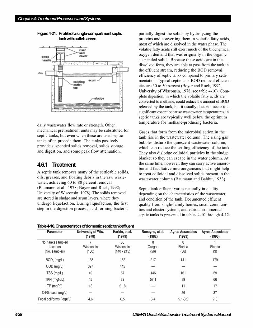
Chapter 4: Treatment Processes and Systems
4-38 USEPA Onsite Wastewater Treatment Systems Manual
daily wastewater flow rate or strength. Other
mechanical pretreatment units may be substituted for
septic tanks, but even when these are used septic
tanks often precede them. The tanks passively
provide suspended solids removal, solids storage
and digestion, and some peak flow attenuation.
4.6.1 TreatmentA septic tank removes many of the settleable solids,
oils, greases, and floating debris in the raw waste-
water, achieving 60 to 80 percent removal
(Baumann et al., 1978; Boyer and Rock, 1992;
University of Wisconsin, 1978). The solids removed
are stored in sludge and scum layers, where they
undergo liquefaction. During liquefaction, the first
step in the digestion process, acid-forming bacteria
partially digest the solids by hydrolyzing the
proteins and converting them to volatile fatty acids,
most of which are dissolved in the water phase. The
volatile fatty acids still exert much of the biochemical
oxygen demand that was originally in the organic
suspended solids. Because these acids are in the
dissolved form, they are able to pass from the tank in
the effluent stream, reducing the BOD removal
efficiency of septic tanks compared to primary sedi-
mentation. Typical septic tank BOD removal efficien-
cies are 30 to 50 percent (Boyer and Rock, 1992;
University of Wisconsin, 1978; see table 4-10). Com-
plete digestion, in which the volatile fatty acids are
converted to methane, could reduce the amount of BOD
released by the tank, but it usually does not occur to a
significant extent because wastewater temperatures in
septic tanks are typically well below the optimum
temperature for methane-producing bacteria.
Gases that form from the microbial action in the
tank rise in the wastewater column. The rising gas
bubbles disturb the quiescent wastewater column,
which can reduce the settling efficiency of the tank.
They also dislodge colloidal particles in the sludge
blanket so they can escape in the water column. At
the same time, however, they can carry active anaero-
bic and facultative microorganisms that might help
to treat colloidal and dissolved solids present in the
wastewater column (Baumann and Babbit, 1953).
Septic tank effluent varies naturally in quality
depending on the characteristics of the wastewater
and condition of the tank. Documented effluent
quality from single-family homes, small communi-
ties and cluster systems, and various commercial
septic tanks is presented in tables 4-10 through 4-12.
Table 4-10. Characteristics of domestic septic tank effluent
Figure 4-21. Profile of a single-compartment septic
tank with outlet screen
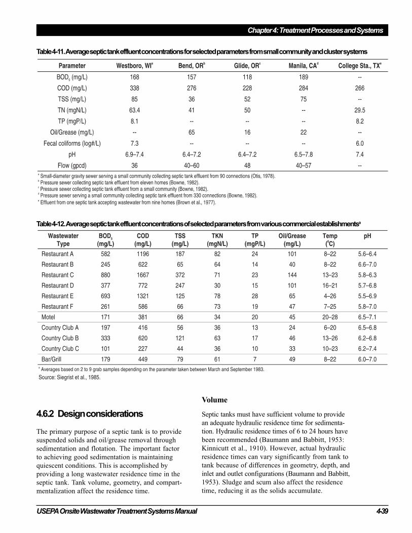
USEPA Onsite Wastewater Treatment Systems Manual 4-39
Chapter 4: Treatment Processes and Systems
4.6.2 Design considerations
The primary purpose of a septic tank is to provide
suspended solids and oil/grease removal through
sedimentation and flotation. The important factor
to achieving good sedimentation is maintaining
quiescent conditions. This is accomplished by
providing a long wastewater residence time in the
septic tank. Tank volume, geometry, and compart-
mentalization affect the residence time.
Volume
Septic tanks must have sufficient volume to provide
an adequate hydraulic residence time for sedimenta-
tion. Hydraulic residence times of 6 to 24 hours have
been recommended (Baumann and Babbitt, 1953:
Kinnicutt et al., 1910). However, actual hydraulic
residence times can vary significantly from tank to
tank because of differences in geometry, depth, and
inlet and outlet configurations (Baumann and Babbitt,
1953). Sludge and scum also affect the residence
time, reducing it as the solids accumulate.
Table 4-12. Average septic tank effluent concentrations of selected parameters from various commercial establishmentsa
Table 4-11. Average septic tank effluent concentrations for selected parameters from small community and cluster systems
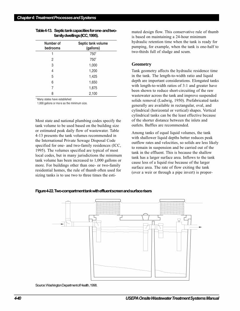
Chapter 4: Treatment Processes and Systems
4-40 USEPA Onsite Wastewater Treatment Systems Manual
Most state and national plumbing codes specify the
tank volume to be used based on the building size
or estimated peak daily flow of wastewater. Table
4-13 presents the tank volumes recommended in
the International Private Sewage Disposal Code
specified for one- and two-family residences (ICC,
1995). The volumes specified are typical of most
local codes, but in many jurisdictions the minimum
tank volume has been increased to 1,000 gallons or
more. For buildings other than one- or two-family
residential homes, the rule of thumb often used for
sizing tanks is to use two to three times the esti-
mated design flow. This conservative rule of thumb
is based on maintaining a 24-hour minimum
hydraulic retention time when the tank is ready for
pumping, for example, when the tank is one-half to
two-thirds full of sludge and scum.
GeometryTank geometry affects the hydraulic residence time
in the tank. The length-to-width ratio and liquid
depth are important considerations. Elongated tanks
with length-to-width ratios of 3:1 and greater have
been shown to reduce short-circuiting of the raw
wastewater across the tank and improve suspended
solids removal (Ludwig, 1950). Prefabricated tanks
generally are available in rectangular, oval, and
cylindrical (horizontal or vertical) shapes. Vertical
cylindrical tanks can be the least effective because
of the shorter distance between the inlets and
outlets. Baffles are recommended.
Among tanks of equal liquid volumes, the tank
with shallower liquid depths better reduces peak
outflow rates and velocities, so solids are less likely
to remain in suspension and be carried out of the
tank in the effluent. This is because the shallow
tank has a larger surface area. Inflows to the tank
cause less of a liquid rise because of the larger
surface area. The rate of flow exiting the tank
(over a weir or through a pipe invert) is propor-
Figure 4-22. Two-compartment tank with effluent screen and surface risers
Source: Washington Department of Health, 1998.
Table 4-13. Septic tank capacities for one- and two-
family dwellings (ICC, 1995).
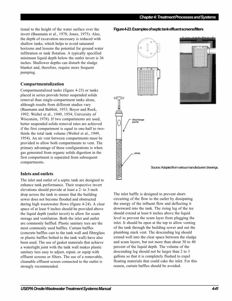
USEPA Onsite Wastewater Treatment Systems Manual 4-41
Chapter 4: Treatment Processes and Systems
tional to the height of the water surface over the
invert (Baumann et al., 1978; Jones, 1975). Also,
the depth of excavation necessary is reduced with
shallow tanks, which helps to avoid saturated
horizons and lessens the potential for ground water
infiltration or tank flotation. A typically specified
minimum liquid depth below the outlet invert is 36
inches. Shallower depths can disturb the sludge
blanket and, therefore, require more frequent
pumping.
Compartmentalization
Compartmentalized tanks (figure 4-23) or tanks
placed in series provide better suspended solids
removal than single-compartment tanks alone,
although results from different studies vary
(Baumann and Babbitt, 1953; Boyer and Rock,
1992; Weibel et al., 1949, 1954; University of
Wisconsin, 1978). If two compartments are used,
better suspended solids removal rates are achieved
if the first compartment is equal to one-half to two-
thirds the total tank volume (Weibel et al., 1949,
1954). An air vent between compartments must be
provided to allow both compartments to vent. The
primary advantage of these configurations is when
gas generated from organic solids digestion in the
first compartment is separated from subsequent
compartments.
Inlets and outlets
The inlet and outlet of a septic tank are designed to
enhance tank performance. Their respective invert
elevations should provide at least a 2- to 3-inch
drop across the tank to ensure that the building
sewer does not become flooded and obstructed
during high wastewater flows (figure 4-24). A clear
space of at least 9 inches should be provided above
the liquid depth (outlet invert) to allow for scum
storage and ventilation. Both the inlet and outlet
are commonly baffled. Plastic sanitary tees are the
most commonly used baffles. Curtain baffles
(concrete baffles cast to the tank wall and fiberglass
or plastic baffles bolted to the tank wall) have also
been used. The use of gasket materials that achieve
a watertight joint with the tank wall makes plastic
sanitary tees easy to adjust, repair, or equip with
effluent screens or filters. The use of a removable,
cleanable effluent screen connected to the outlet is
strongly recommended.
The inlet baffle is designed to prevent short-
circuiting of the flow to the outlet by dissipating
the energy of the influent flow and deflecting it
downward into the tank. The rising leg of the tee
should extend at least 6 inches above the liquid
level to prevent the scum layer from plugging the
inlet. It should be open at the top to allow venting
of the tank through the building sewer and out the
plumbing stack vent. The descending leg should
extend well into the clear space between the sludge
and scum layers, but not more than about 30 to 40
percent of the liquid depth. The volume of the
descending leg should not be larger than 2 to 3
gallons so that it is completely flushed to expel
floating materials that could cake the inlet. For this
reason, curtain baffles should be avoided.
Figure 4-23. Examples of septic tank effluent screens/filters
Source: Adapted from various manufacturers’ drawings.

Chapter 4: Treatment Processes and Systems
4-42 USEPA Onsite Wastewater Treatment Systems Manual
The outlet baffle is designed to draw effluent from
the clear zone between the sludge and scum layers.
The rising leg of the tee should extend 6 inches
above the liquid level to prevent the scum layer
from escaping the tank. The descending leg should
extend to 30 or 40 percent of the liquid depth.
Effluent screens (commonly called septic tank
filters), which can be fitted to septic tank outlets,
are commercially available. Screens prevent solids
that either are buoyant or are resuspended from the
scum or sludge layers from passing out of the tank
(figures 4-22 and 4-23). Mesh, slotted screens, and
stacked plates with openings from 1/32 to 1/8 inch
are available. Usually, the screens can be fitted into
the existing outlet tee or retrofitted directly into the
outlet. An access port directly above the outlet is
required so the screen can be removed for inspec-
tion and cleaning.
Quality-assured, reliable test results have not shown
conclusively that effluent screens result in effluents
with significantly lower suspended solids and BOD
concentrations. However, they provide an excellent,
low-cost safeguard against neutral-buoyancy solids
and high suspended solids in the tank effluent
resulting from solids digestion or other upsets.
Also, as the effluent screens clog over time, slower
draining and flushing of home fixtures may alert
homeowners of the need for maintenance before
complete blockage occurs.
Tank access
Access to the septic tank is necessary for pumping
septage, observing the inlet and outlet baffles, and
servicing the effluent screen. Both manways and
inspection ports are used. Manways are large
openings, 18 to 24 inches in diameter or square. At
least one that can provide access to the entire tank
for septage removal is needed. If the system is
compartmentalized, each compartment requires a
manway. They are located over the inlet, the outlet,
or the center of the tank. Typically, in the past
manway covers were required to be buried under
state and local codes. However, they should be
above grade and fitted with an airtight, lockable
cover so they can be accessed quickly and easily.
Inspection ports are 8 inches or larger in diameter
and located over both the inlet and the outlet unless
a manway is used. They should be extended above
grade and securely capped.
(CAUTION: The screen should not be removed for
inspection or cleaning without first plugging the
outlet or pumping the tank to lower the liquid level
below the outlet invert. Solids retained on the screen
can slough off as the screen is removed. These
solids will pass through the outlet and into the
SWIS unless precautions are taken. This caution
should be made clear in homeowner instructions
and on notices posted at the access port.)
Septic tank designs for large wastewater flows do
not differ from designs for small systems. How-
ever, it is suggested that multiple compartments or
tanks in series be used and that effluent screens be
attached to the tank outlet. Access ports and
manways should be brought to grade and provided
with locking covers for all large systems.
Construction materials
Septic tanks smaller than 6,000 gallons are typi-
cally premanufactured; larger tanks are constructed
in place. The materials used in premanufactured
tanks include concrete, fiberglass, polyethylene,
and coated steel. Precast concrete tanks are by far
the most common, but fiberglass and plastic tanks
are gaining popularity. The lighter weight fiber-
glass and plastic tanks can be shipped longer
distances and set in place without cranes. Concrete
tanks, on the other hand, are less susceptible to
collapse and flotation. Coated steel tanks are no
longer widely used because they corrode easily.
Tanks constructed in place are typically made of
concrete.
Tanks constructed of fiberglass-reinforced polyester
(FRP) usually have a wall thickness of about 1/4
inch (6 millimeters). Most are gel- or resin-coated
to provide a smooth finish and prevent glass fibers
from becoming exposed, which can cause wicking.
Polyethylene tanks are more flexible than FRP
tanks and can deform to a shape of structural
weakness if not properly designed. Concrete tank
walls are usually about 4 inches thick and rein-
forced with no. 5 rods on 8-inch (20-centimeter)
centers. Sulfuric acid and hydrogen sulfide, both of
which are present in varying concentrations in
septic tank effluent, can corrode exposed rods and
the concrete itself over time. Some plastics (e.g.,
polyvinyl chloride, polyethylene, but not nylon)
are virtually unaffected by acids and hydrogen
sulfide (USEPA, 1991).
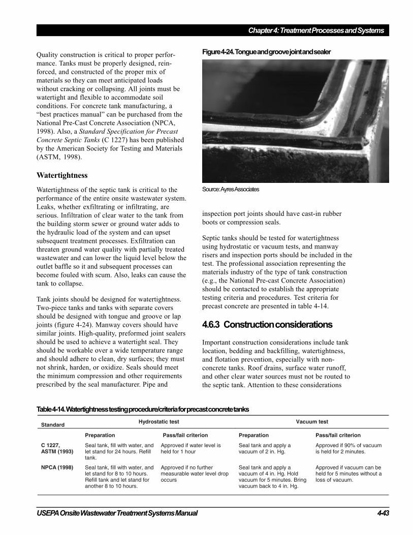
USEPA Onsite Wastewater Treatment Systems Manual 4-43
Chapter 4: Treatment Processes and Systems
Quality construction is critical to proper perfor-
mance. Tanks must be properly designed, rein-
forced, and constructed of the proper mix of
materials so they can meet anticipated loads
without cracking or collapsing. All joints must be
watertight and flexible to accommodate soil
conditions. For concrete tank manufacturing, a
“best practices manual” can be purchased from the
National Pre-Cast Concrete Association (NPCA,
1998). Also, a Standard Specification for Precast
Concrete Septic Tanks (C 1227) has been published
by the American Society for Testing and Materials
(ASTM, 1998).
Watertightness
Watertightness of the septic tank is critical to the
performance of the entire onsite wastewater system.
Leaks, whether exfiltrating or infiltrating, are
serious. Infiltration of clear water to the tank from
the building storm sewer or ground water adds to
the hydraulic load of the system and can upset
subsequent treatment processes. Exfiltration can
threaten ground water quality with partially treated
wastewater and can lower the liquid level below the
outlet baffle so it and subsequent processes can
become fouled with scum. Also, leaks can cause the
tank to collapse.
Tank joints should be designed for watertightness.
Two-piece tanks and tanks with separate covers
should be designed with tongue and groove or lap
joints (figure 4-24). Manway covers should have
similar joints. High-quality, preformed joint sealers
should be used to achieve a watertight seal. They
should be workable over a wide temperature range
and should adhere to clean, dry surfaces; they must
not shrink, harden, or oxidize. Seals should meet
the minimum compression and other requirements
prescribed by the seal manufacturer. Pipe and
inspection port joints should have cast-in rubber
boots or compression seals.
Septic tanks should be tested for watertightness
using hydrostatic or vacuum tests, and manway
risers and inspection ports should be included in the
test. The professional association representing the
materials industry of the type of tank construction
(e.g., the National Pre-cast Concrete Association)
should be contacted to establish the appropriate
testing criteria and procedures. Test criteria for
precast concrete are presented in table 4-14.
4.6.3 Construction considerations
Important construction considerations include tank
location, bedding and backfilling, watertightness,
and flotation prevention, especially with non-
concrete tanks. Roof drains, surface water runoff,
and other clear water sources must not be routed to
the septic tank. Attention to these considerations
Table 4-14. Watertightness testing procedure/criteria for precast concrete tanks
Figure 4-24. Tongue and groove joint and sealer
Source: Ayres Associates

Chapter 4: Treatment Processes and Systems
4-44 USEPA Onsite Wastewater Treatment Systems Manual
will help to ensure that the tank performs as
intended.
Location
The tank should be located where it can be accessed
easily for septage removal and sited away from
drainage swales or depressions where water can
collect. Local codes must be consulted regarding
minimum horizontal setback distances from
buildings, property boundaries, wells, water lines,
and the like.
Bedding and backfilling
The tank should rest on a uniform bearing surface.
It is good practice to provide a level, granular base
for the tank. The underlying soils must be capable
of bearing the weight of the tank and its contents.
Soils with a high organic content or containing
large boulders or massive rock edges are not
suitable.
After setting the tank, leveling, and joining the
building sewer and effluent line, the tank can be
backfilled. The backfill material should be free-
flowing and free of stones larger than 3 inches in
diameter, debris, ice, or snow. It should be added in
lifts and each lift compacted. In fine-textured soils
such as silts, silt loams, clay loams, and clay,
imported granular material should be used. This is
a must where freeze and thaw cycles are common
because the soil movement during such cycles can
work tank joints open. This is a significant concern
when using plastic and fiberglass tanks.
The specific bedding and backfilling requirements
vary with the shape and material of the tank. The
manufacturer should be consulted for acceptable
materials and procedures.
Watertightness
All joints must be sealed properly, including tank
joints (sections and covers if not a monolithic
tank), inlets, outlets, manways, and risers (ASTM,
1993; NPCA, 1998). The joints should be clean
and dry before applying the joint sealer. Only high-
quality joint sealers should be used (see previous
section). Backfilling should not proceed until the
sealant setup period is completed. After all joints
have been made and have cured, a watertightness
test should be performed (see table 4-14 for precast
concrete tanks). Risers should be tested.
Flotation prevention
If the tank is set where the soil can be saturated,
tank flotation may occur, particularly when the
tank is empty (e.g., recently pumped dose tanks or
septic tank after septage removal). Tank manufac-
turers should be consulted for appropriate
antiflotation devices.
4.6.4 Operation and maintenance
The septic tank is a passive treatment unit that
typically requires little operator intervention.
Regular inspections, septage pumping, and periodic
cleaning of the effluent filter or screen are the only
operation and maintenance requirements. Commer-
cially available microbiological and enzyme
additives are promoted to reduce sludge and scum
accumulations in septic tanks. They are not neces-
sary for the septic tank to function properly when
treating domestic wastewaters. Results from studies
to evaluate their effectiveness have failed to prove
their cost-effectiveness for residential application.
For most products, concentrations of suspended
solids and BOD in the septic tank effluent increase
upon their use, posing a threat to SWIS perfor-
mance. No additive made up of organic solvents or
strong alkali chemicals should be used because they
pose a potential threat to soil structure and ground
water.
Inspections
Inspections are performed to observe sludge and
scum accumulations, structural soundness, water-
tightness, and condition of the inlet and outlet
baffles and screens. (Warning: In performing
inspections or other maintenance, the tank should
not be entered. The septic tank is a confined space
and entering can be extremely hazardous because of
toxic gases and/or insufficient oxygen.)
Sludge and scum accumulations
As wastewater passes through and is partially
treated in the septic tank over the years, the layers
of floatable material (scum) and settleable material
(sludge) increase in thickness and gradually reduce
the amount of space available for clarified waste-
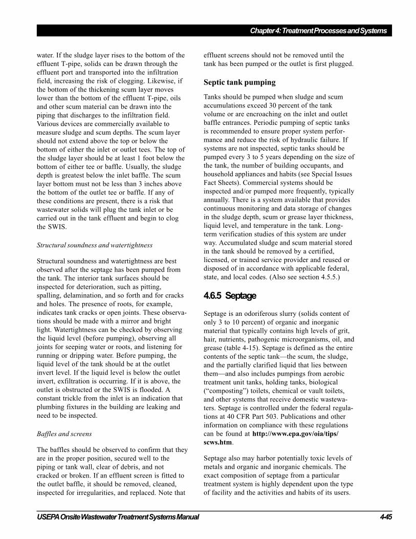
USEPA Onsite Wastewater Treatment Systems Manual 4-45
Chapter 4: Treatment Processes and Systems
water. If the sludge layer rises to the bottom of the
effluent T-pipe, solids can be drawn through the
effluent port and transported into the infiltration
field, increasing the risk of clogging. Likewise, if
the bottom of the thickening scum layer moves
lower than the bottom of the effluent T-pipe, oils
and other scum material can be drawn into the
piping that discharges to the infiltration field.
Various devices are commercially available to
measure sludge and scum depths. The scum layer
should not extend above the top or below the
bottom of either the inlet or outlet tees. The top of
the sludge layer should be at least 1 foot below the
bottom of either tee or baffle. Usually, the sludge
depth is greatest below the inlet baffle. The scum
layer bottom must not be less than 3 inches above
the bottom of the outlet tee or baffle. If any of
these conditions are present, there is a risk that
wastewater solids will plug the tank inlet or be
carried out in the tank effluent and begin to clog
the SWIS.
Structural soundness and watertightness
Structural soundness and watertightness are best
observed after the septage has been pumped from
the tank. The interior tank surfaces should be
inspected for deterioration, such as pitting,
spalling, delamination, and so forth and for cracks
and holes. The presence of roots, for example,
indicates tank cracks or open joints. These observa-
tions should be made with a mirror and bright
light. Watertightness can be checked by observing
the liquid level (before pumping), observing all
joints for seeping water or roots, and listening for
running or dripping water. Before pumping, the
liquid level of the tank should be at the outlet
invert level. If the liquid level is below the outlet
invert, exfiltration is occurring. If it is above, the
outlet is obstructed or the SWIS is flooded. A
constant trickle from the inlet is an indication that
plumbing fixtures in the building are leaking and
need to be inspected.
Baffles and screens
The baffles should be observed to confirm that they
are in the proper position, secured well to the
piping or tank wall, clear of debris, and not
cracked or broken. If an effluent screen is fitted to
the outlet baffle, it should be removed, cleaned,
inspected for irregularities, and replaced. Note that
effluent screens should not be removed until the
tank has been pumped or the outlet is first plugged.
Septic tank pumping
Tanks should be pumped when sludge and scum
accumulations exceed 30 percent of the tank
volume or are encroaching on the inlet and outlet
baffle entrances. Periodic pumping of septic tanks
is recommended to ensure proper system perfor-
mance and reduce the risk of hydraulic failure. If
systems are not inspected, septic tanks should be
pumped every 3 to 5 years depending on the size of
the tank, the number of building occupants, and
household appliances and habits (see Special Issues
Fact Sheets). Commercial systems should be
inspected and/or pumped more frequently, typically
annually. There is a system available that provides
continuous monitoring and data storage of changes
in the sludge depth, scum or grease layer thickness,
liquid level, and temperature in the tank. Long-
term verification studies of this system are under
way. Accumulated sludge and scum material stored
in the tank should be removed by a certified,
licensed, or trained service provider and reused or
disposed of in accordance with applicable federal,
state, and local codes. (Also see section 4.5.5.)
4.6.5 Septage
Septage is an odoriferous slurry (solids content of
only 3 to 10 percent) of organic and inorganic
material that typically contains high levels of grit,
hair, nutrients, pathogenic microorganisms, oil, and
grease (table 4-15). Septage is defined as the entire
contents of the septic tank—the scum, the sludge,
and the partially clarified liquid that lies between
them—and also includes pumpings from aerobic
treatment unit tanks, holding tanks, biological
(“composting”) toilets, chemical or vault toilets,
and other systems that receive domestic wastewa-
ters. Septage is controlled under the federal regula-
tions at 40 CFR Part 503. Publications and other
information on compliance with these regulations
can be found at http://www.epa.gov/oia/tips/
scws.htm.
Septage also may harbor potentially toxic levels of
metals and organic and inorganic chemicals. The
exact composition of septage from a particular
treatment system is highly dependent upon the type
of facility and the activities and habits of its users.
Chapter 4: Treatment Processes and Systems
4-46 USEPA Onsite Wastewater Treatment Systems Manual
For example, oil and grease levels in septage from
food service or processing facilities might be many
times higher than oil and grease concentrations in
septage from residences (see Special Issues Fact
Sheets). Campgrounds that have separate graywater
treatment systems for showers will likely have
much higher levels of solids in the septage from the
blackwater (i.e., toilet waste) treatment system.
Septage from portable toilets might have been
treated with disinfectants, deodorizers, or other
chemicals.
Septage management programs
The primary objective of a septage management
program is to establish procedures and rules for
handling and disposing of septage in an affordable
manner that protects public health and ecological
resources. When planning a program it is important
to have a thorough knowledge of legal and regula-
tory requirements regarding handling and disposal.
USEPA (1994) has issued regulations and guidance
that contain the type of information required for
developing, implementing, and maintaining a
septage management program. Detailed guidance
for identifying, selecting, developing, and operat-
ing reuse or disposal sites for septage is provided in
Process Design Manual: Surface Disposal of
Sewage Sludge and Domestic Septage (USEPA,
1995b), which is on the Internet at http://
www.epa.gov/ORD/WebPubs/sludge.pdf. Addi-
tional information can be found in Domestic
Septage Regulatory Guidance (USEPA, 1993), at
http://www.epa.gov/oia/tips/scws.htm.
States and municipalities typically establish public
health and environmental protection regulations for
septage management (pumping, handling, trans-
port, treatment, and reuse/disposal). Key compo-
nents of septage management programs include
tracking or manifest systems that identify accept-
able septage sources, pumpers, transport equip-
ment, final destination, and treatment, as well as
procedures for controlling human exposure to
septage, including vector control, wet weather
runoff, and access to disposal sites.
Septage treatment/disposal: land
application
The ultimate fate of septage generally falls into
three basic categories—land application, treatment
at a wastewater treatment plant, or treatment at a
special septage treatment plant. Land application is
the most commonly used method for disposing of
septage in the United States. Simple and cost-
effective, land application approaches use minimal
energy and recycle organic material and nutrients
back to the land. Topography, soils, drainage
patterns, and agricultural crops determine which
type of land disposal practice works best for a
given situation. Some common alternatives are
surface application, subsurface incorporation, and
burial. Disposal of portable toilet wastes mixed
with disinfectants, deodorizers, or other chemicals
at land application sites is not recommended. If
possible, these wastes should be delivered to the
collection system of a wastewater treatment plant to
avoid potential chemical contamination risks at
septage land application sites. Treatment plant
operators should be consulted so they can deter-
mine when and where the septage should be added
to the collection system.
When disposing of septage by land application,
appropriate buffers and setbacks should be pro-
vided between application areas and water re-
sources (e.g., streams, lakes, sinkholes). Other
considerations include vegetation type and density,
slopes, soils, sensitivity of water resources, climate,
Table 4-15. Chemical and physical characteristics of domestic
septage
USEPA Onsite Wastewater Treatment Systems Manual 4-47
Chapter 4: Treatment Processes and Systems
and application rates. Agricultural products from
the site must not be directly consumed by humans.
Land application practices include the following:
Spreading by hauler truck or farm equipment
In the simplest method, the truck that pumps the
septage takes it to a field and spreads it on the soil.
Alternatively, the hauler truck can transfer its
septage load into a wagon spreader or other special-
ized spreading equipment or into a holding facility
at the site for spreading later.
Spray irrigation
Spray irrigation is an alternative that eliminates the
problem of soil compaction by tires. Pretreated
septage is pumped at 80 to 100 psi through nozzles
and sprayed directly onto the land. This method
allows for septage disposal on fields with rough
terrain.
Ridge and furrow irrigation
Pretreated septage can be transferred directly into
furrows or row crops. The land should be relatively
level.
Subsurface incorporation of septage
This alternative to surface application involves
placing untreated septage just below the surface.
This approach reduces odors and health risks while
still fertilizing and conditioning the soil. The
method can be applied only on relatively flat land
(less than 8 percent slope) in areas where the
seasonally high water table is at least 20 inches.
Because soil compaction is a concern, no vehicles
should be allowed to drive on the field for 1 to 2
weeks after application. Subsurface application
practices include the following:
• Plow and furrow irrigation: In this simple
method, a plow creates a narrow furrow 6 to 8
inches (15 to 20 centimeters) deep. Liquid
septage is discharged from a tank into the
furrow, and a second plow covers the furrow.
• Subsurface injection: A tillage tool is used to
create a narrow cavity 4 to 6 inches (10 to 15
centimeters) deep. Liquid septage is injected
into the cavity, and the hole is covered.
Codisposal of septage in sanitary landfills
Because of the pollution risks associated with
runoff and effluent leaching into ground water,
landfill disposal of septage is not usually a viable
option. However, some jurisdictions may allow
disposal of septage/soil mixtures or permit other
special disposal options for dewatered septage
(sludge with at least 20 percent solids). Septage or
sludge deposited in a landfill should be covered
immediately with at least 6 inches of soil to control
odors and vector access (USEPA, 1995b). (Note:
Codisposal of sewage sludge or domestic septage at
a municipal landfill is considered surface disposal
and is regulated under 40 CFR Part 258.)
Septage treatment/disposal: treatmentplantsDisposal of septage at a wastewater treatment plant
is often a convenient and cost-effective option.
Addition of septage requires special care and
handling because by nature septage is more concen-
trated than the influent wastewater stream at the
treatment plant. Therefore, there must be adequate
capacity at the plant to handle and perhaps tempo-
rarily store delivered septage until it can be fed into
the treatment process units. Sites that typically
serve as the input point for septage to be treated at
a wastewater treatment plant include the following:
Upstream sewer manhole
This alternative is viable for larger sewer systems
and treatment plants. Septage is added to the
normal influent wastewater flow at a receiving
station fitted with an access manhole.
Treatment plant headworks
The septage is added at the treatment plant up-
stream of the inlet screens and grit chambers. The
primary concern associated with this option is the
impact of the introduced wastes on treatment unit
processes in the plant. A thorough analysis should
be conducted to ensure that plant processes can
accept and treat the wastes while maintaining
appropriate effluent pollutant concentrations and
meeting other treatment requirements. In any
event, the treatment plant operator should be
consulted before disposal.

Chapter 4: Treatment Processes and Systems
4-48 USEPA Onsite Wastewater Treatment Systems Manual
Sludge-handling process
To reduce loading to the liquid stream, the septage
can be sent directly to the sludge-handling process.
Like the headworks option, the impact on the
sludge treatment processes must be carefully
analyzed to ensure that the final product meets
treatment and other requirements.
Treatment at a special septage treatment plant
This method of septage disposal is usually em-
ployed in areas where land disposal or treatment at
a wastewater treatment plant is not a feasible
option. There are few of these facilities, which
vary from simple lagoons to sophisticated plants
that mechanically and/or chemically treat septage.
Treatment processes used include lime stabilization,
chlorine oxidation, aerobic and anaerobic digestion,
composting, and dewatering using pressure or
vacuum filtration or centrifugation. This is the
most expensive option for septage management and
should be considered only as a last resort.
Public outreach and involvement
Developing septage treatment units or land applica-
tion sites requires an effective public outreach
program. Opposition to locating these facilities in
the service area is sometimes based about incom-
plete or inaccurate information, fear of the un-
known, and a lack of knowledge on potential
impacts. Without an effective community-based
program of involvement, even the most reasonable
plan can be difficult to implement. Traditional
guidance on obtaining public input in the develop-
ment of disposal or reuse facilities can be found in
Process Design Manual: Surface Disposal of
Sewage Sludge and Domestic Septage (USEPA,
1995b), which is on the Internet at http://
www.epa.gov/ORD/WebPubs/sludge.pdf.
Additional information can be found in Domestic
Septage Regulatory Guidance (USEPA, 1993),
posted at http://www.epa.gov/oia/tips/scws.htm.
General guidance on developing and implementing
a public outreach strategy is available in Getting In
Step: A Guide to Effective Outreach in Your
Watershed, published by the Council of State
Governments (see chapter 2) and available at http:/
/www.epa.gov/owow/watershed/outreach/
documents/.
4.7 Sand/media filters
Sand (or other media) filters are used to provide
advanced treatment of settled wastewater or septic
tank effluent. They consist of a lined (lined with
impervious PVC liner on sand bedding) excavation
or watertight structure filled with uniformly sized
washed sand (the medium) that is normally placed
over an underdrain system (figure 4-25). These
contained media filters are also known as packed
bed filters. The wastewater is dosed onto the
surface of the sand through a distribution network
and is allowed to percolate through the sand to the
underdrain system. The underdrain collects the
filtrate for further processing, recycling, or dis-
charging to a SWIS. Some “bottomless” designs
directly infiltrate the filtered effluent into the soil
below.
4.7.1 Treatment mechanisms and filterdesign
Sand filters are essentially aerobic, fixed-film
bioreactors used to treat septic tank effluent. Other
very important treatment mechanisms that occur in
sand filters include physical processes such as
straining and sedimentation, which remove sus-
pended solids within the pores of the media, and
chemical adsorption of dissolved pollutants (e.g.,
phosphorus) to media surfaces. The latter phenom-
enon tends to be finite because adsorption sites
become saturated with the adsorbed compound, and
it is specific to the medium chosen. Bioslimes from
the growth of microorganisms develop as attached
films on the sand particle surfaces. The microorgan-
isms in the slimes absorb soluble and colloidal waste
materials in the wastewater as it percolates around
the sand surfaces. The absorbed materials are
incorporated into new cell mass or degraded under
aerobic conditions to carbon dioxide and water.
Figure 4-25. Underdrain system detail for sand filters
����������������
��������������������������������
������������������������������������������������
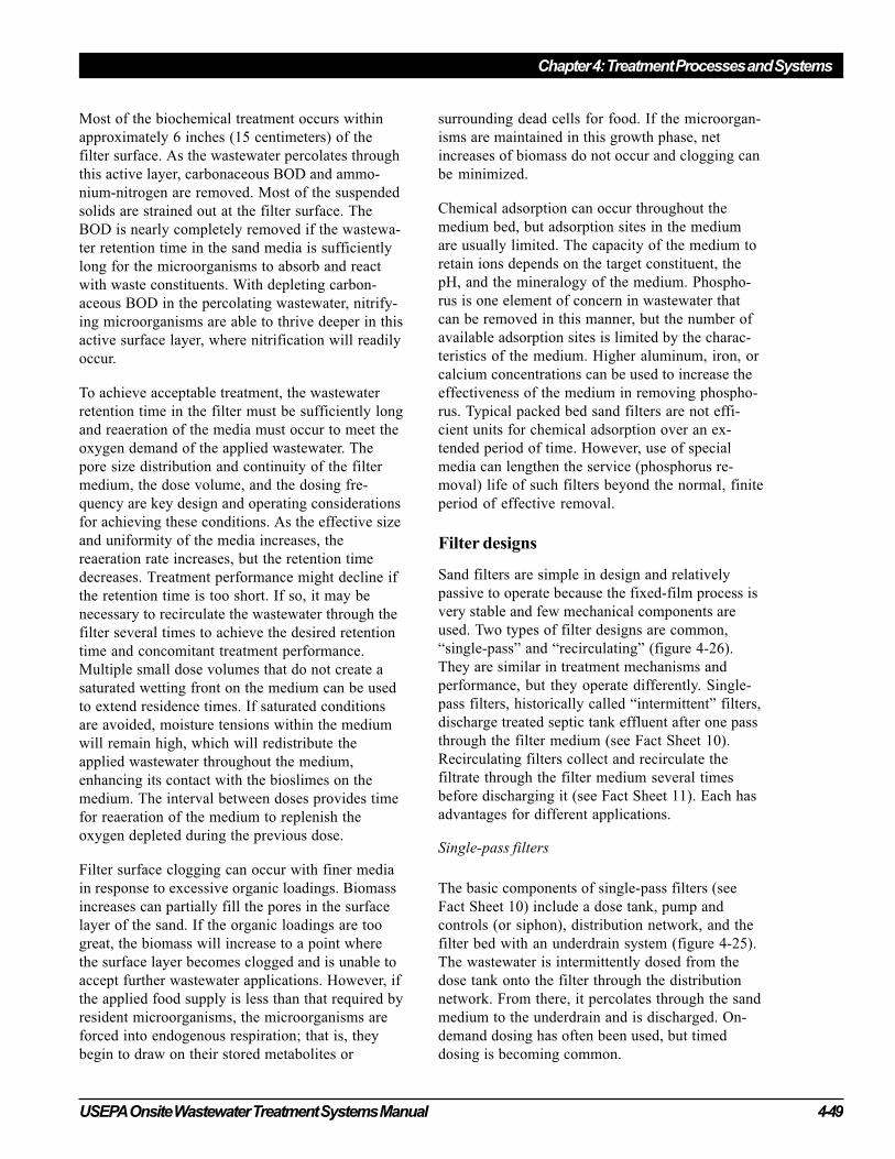
USEPA Onsite Wastewater Treatment Systems Manual 4-49
Chapter 4: Treatment Processes and Systems
Most of the biochemical treatment occurs within
approximately 6 inches (15 centimeters) of the
filter surface. As the wastewater percolates through
this active layer, carbonaceous BOD and ammo-
nium-nitrogen are removed. Most of the suspended
solids are strained out at the filter surface. The
BOD is nearly completely removed if the wastewa-
ter retention time in the sand media is sufficiently
long for the microorganisms to absorb and react
with waste constituents. With depleting carbon-
aceous BOD in the percolating wastewater, nitrify-
ing microorganisms are able to thrive deeper in this
active surface layer, where nitrification will readily
occur.
To achieve acceptable treatment, the wastewater
retention time in the filter must be sufficiently long
and reaeration of the media must occur to meet the
oxygen demand of the applied wastewater. The
pore size distribution and continuity of the filter
medium, the dose volume, and the dosing fre-
quency are key design and operating considerations
for achieving these conditions. As the effective size
and uniformity of the media increases, the
reaeration rate increases, but the retention time
decreases. Treatment performance might decline if
the retention time is too short. If so, it may be
necessary to recirculate the wastewater through the
filter several times to achieve the desired retention
time and concomitant treatment performance.
Multiple small dose volumes that do not create a
saturated wetting front on the medium can be used
to extend residence times. If saturated conditions
are avoided, moisture tensions within the medium
will remain high, which will redistribute the
applied wastewater throughout the medium,
enhancing its contact with the bioslimes on the
medium. The interval between doses provides time
for reaeration of the medium to replenish the
oxygen depleted during the previous dose.
Filter surface clogging can occur with finer media
in response to excessive organic loadings. Biomass
increases can partially fill the pores in the surface
layer of the sand. If the organic loadings are too
great, the biomass will increase to a point where
the surface layer becomes clogged and is unable to
accept further wastewater applications. However, if
the applied food supply is less than that required by
resident microorganisms, the microorganisms are
forced into endogenous respiration; that is, they
begin to draw on their stored metabolites or
surrounding dead cells for food. If the microorgan-
isms are maintained in this growth phase, net
increases of biomass do not occur and clogging can
be minimized.
Chemical adsorption can occur throughout the
medium bed, but adsorption sites in the medium
are usually limited. The capacity of the medium to
retain ions depends on the target constituent, the
pH, and the mineralogy of the medium. Phospho-
rus is one element of concern in wastewater that
can be removed in this manner, but the number of
available adsorption sites is limited by the charac-
teristics of the medium. Higher aluminum, iron, or
calcium concentrations can be used to increase the
effectiveness of the medium in removing phospho-
rus. Typical packed bed sand filters are not effi-
cient units for chemical adsorption over an ex-
tended period of time. However, use of special
media can lengthen the service (phosphorus re-
moval) life of such filters beyond the normal, finite
period of effective removal.
Filter designs
Sand filters are simple in design and relatively
passive to operate because the fixed-film process is
very stable and few mechanical components are
used. Two types of filter designs are common,
“single-pass” and “recirculating” (figure 4-26).
They are similar in treatment mechanisms and
performance, but they operate differently. Single-
pass filters, historically called “intermittent” filters,
discharge treated septic tank effluent after one pass
through the filter medium (see Fact Sheet 10).
Recirculating filters collect and recirculate the
filtrate through the filter medium several times
before discharging it (see Fact Sheet 11). Each has
advantages for different applications.
Single-pass filters
The basic components of single-pass filters (see
Fact Sheet 10) include a dose tank, pump and
controls (or siphon), distribution network, and the
filter bed with an underdrain system (figure 4-25).
The wastewater is intermittently dosed from the
dose tank onto the filter through the distribution
network. From there, it percolates through the sand
medium to the underdrain and is discharged. On-
demand dosing has often been used, but timed
dosing is becoming common.
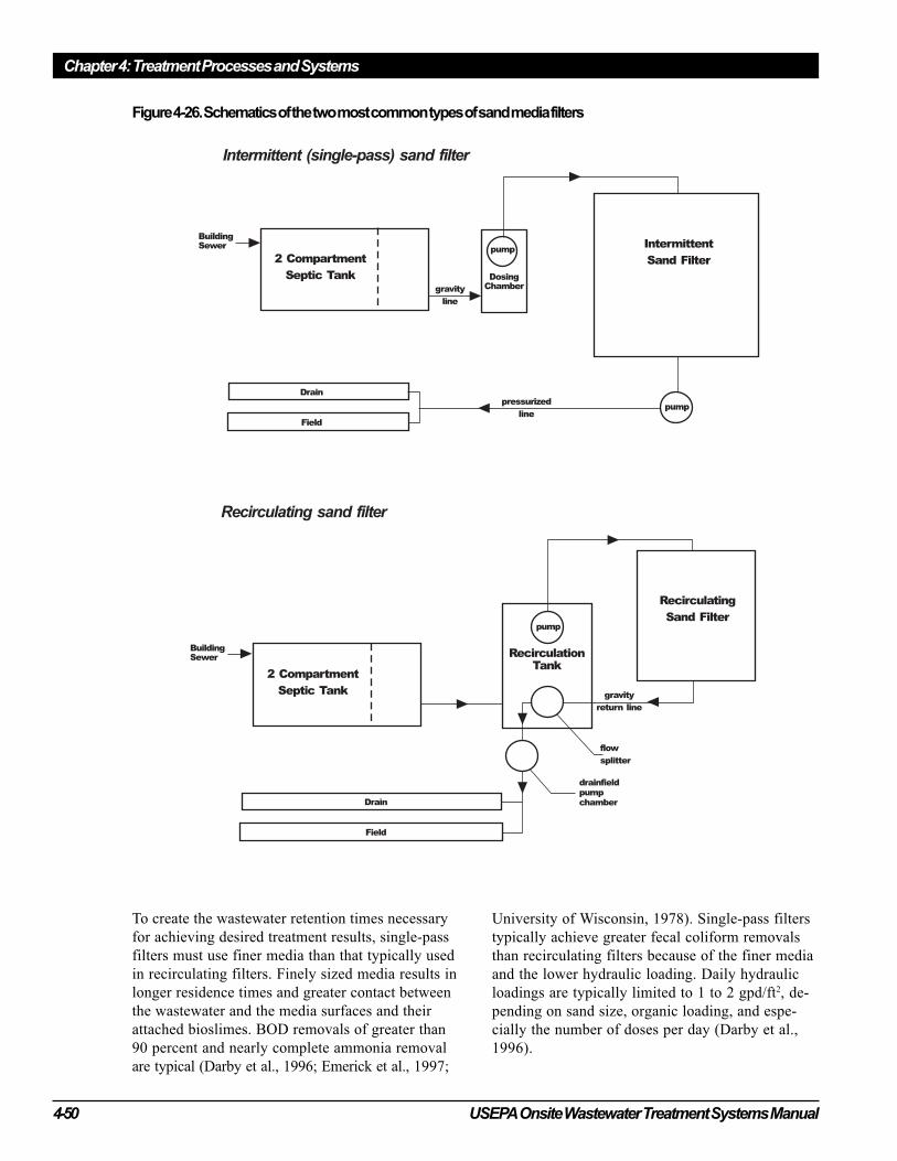
Chapter 4: Treatment Processes and Systems
4-50 USEPA Onsite Wastewater Treatment Systems Manual
To create the wastewater retention times necessary
for achieving desired treatment results, single-pass
filters must use finer media than that typically used
in recirculating filters. Finely sized media results in
longer residence times and greater contact between
the wastewater and the media surfaces and their
attached bioslimes. BOD removals of greater than
90 percent and nearly complete ammonia removal
are typical (Darby et al., 1996; Emerick et al., 1997;
University of Wisconsin, 1978). Single-pass filters
typically achieve greater fecal coliform removals
than recirculating filters because of the finer media
and the lower hydraulic loading. Daily hydraulic
loadings are typically limited to 1 to 2 gpd/ft2, de-
pending on sand size, organic loading, and espe-
cially the number of doses per day (Darby et al.,
1996).
Figure 4-26. Schematics of the two most common types of sand media filters
USEPA Onsite Wastewater Treatment Systems Manual 4-51
Chapter 4: Treatment Processes and Systems
Recirculating filters
The basic components of recirculating filters (see
Fact Sheet 11) are a recirculation/dosing tank,
pump and controls, a distribution network, a filter
bed with an underdrain system, and a return line
fitted with a flow-splitting device to return a
portion of the filtrate to the recirculation/dosing
tank (figure 4-26). The wastewater is dosed to the
filter surface on a timed cycle 1 to 3 times per
hour. The returned filtrate mixes with fresh septic
tank effluent before being returned to the filter.
Media types
Many types of media are used in packed bed filters.
Washed, graded sand is the most common medium.
Other granular media used include gravel, anthra-
cite, crushed glass, expanded shale, and bottom ash
from coal-fired power plants. Bottom ash has been
studied successfully by Swanson and Dix (1987).
Crushed glass has been studied (Darby et al., 1996;
and Emerick et al., 1997), and it was found to
perform similarly to sand of similar size and
uniformity. Expanded shale appears to have been
successful in some field trials in Maryland, but the
data are currently incomplete in relation to long-
term durability of the medium.
Foam chips, peat, and nonwoven coarse-fiber
synthetic textile materials have also been used.
These are generally restricted to proprietary units.
Probably the most studied of these is the peat filter,
which has become fairly common in recent years.
Depending on the type of peat used, the early perfor-
mance of these systems will produce an effluent with
a low pH and a yellowish color. This is accompa-
nied by some excellent removal of organics and
microbes, but would generally not be acceptable as
a surface discharge (because of low pH and visible
color). However, as a pretreatment for a SWIS,
low pH and color are not a problem. Peat must
meet the same hydraulic requirements as sand (see
Fact Sheets 10 and 11). The primary advantage of
the proprietary materials, the expanded shale, and to
some degree the peat is their light weight, which
makes them easy to transport and use at any site.
Some short-term studies of nonwoven fabric filters
have shown promise (Roy and Dube, 1994).
System manufacturers should be contacted for
application and design using these materials.
4.7.2 Applications
Sand media filters may be used for a broad range
of applications, including single-family residences,
large commercial establishments, and small com-
munities. They are frequently used to pretreat
wastewater prior to subsurface infiltration on sites
where the soil has insufficient unsaturated depth
above ground water or bedrock to achieve adequate
treatment. They are also used to meet water quality
requirements before direct discharge to a surface
water. They are used primarily to treat domestic
wastewater, but they have been used successfully in
treatment trains to treat wastewaters high in organic
materials such as those from restaurants and
supermarkets. Single pass filters are most fre-
quently used for smaller applications and sites
where nitrogen removal is not required. Recirculat-
ing filters are used for both large and small flows
Performance of sand and other filters
Twelve innovative treatment technologies were installed to replace failed septic systems in the Narragansett Bay
watershed, which is both pathogen- and nitrogen-sensitive. The technologies installed consisted of an at-grade
recirculating sand filter, single pass sand filters, Maryland-style recirculating sand filters, foam biofilters, and a
recirculating textile filter. The treatment performance of these systems was monitored over an 18-month period. In
the field study, TSS and BOD5 concentrations were typically less than 5 mg/L for all sand filter effluent and less
than 20 mg/L for both the foam biofilter and textile filter effluents. Single pass sand filters achieved substantial
fecal coliform reductions, reaching mean discharge levels ranging from 200 to 520 colonies per 100 mL for all 31
observations. The at-grade recirculating sand filter achieved the highest total nitrogen reductions of any
technology investigated and consistently met the Rhode Island state nitrogen removal standard (a TN reduction of
50 percent or more and a TN concentration of 19 mg/L or less) throughout the study.
Source: Loomis et al., 2001.
Chapter 4: Treatment Processes and Systems
4-52 USEPA Onsite Wastewater Treatment Systems Manual
and are frequently used where nitrogen removal is
necessary. Nitrogen removal of up to 70 to 80
percent can be achieved if an anoxic reactor is used
ahead of the recirculation tank, where the nitrified
return filtrate can be mixed with the carbon-rich
septic tank effluent (Anderson et al., 1998; Boyle
et al., 1994; Piluk and Peters, 1994).
4.7.3 Performance
The treatment performance of single-pass and
recirculating filters is presented in table 4-16. The
medium used was sand or gravel as noted. Recircu-
lating sand filters generally match or outperform
single-pass filters in removal of BOD, TSS, and
nitrogen. Typical effluent concentrations for
domestic wastewater treatment are less than 10 mg/
L for both BOD and TSS, and nitrogen removal is
approximately 50 percent. Single-pass sand filters
can also typically produce an effluent of less than
10 mg/L for both BOD and TSS. Effluent is nearly
completely nitrified, but some variability can be
expected in nitrogen removal capability. Pell and
Nyberg (1989) found typical nitrogen removals of
18 to 33 percent with their intermittent sand filter.
Fecal coliform removal is somewhat better in
single pass filters. Removals range from 2 to 4 logs
in both types of filters. Intermittent sand filter fecal
coliform removal is a function of hydraulic load-
ing; removals decrease as the loading rate increases
above 1 gpm/ft2 (Emerick et al., 1997).
Effluent suspended solids from sand filters are
typically low. The medium retains the solids. Most
of the organic solids are ultimately digested. Gravel
filters, on the other hand, do not retain solids as
well.
excessive solids buildup due to the lack of periodic
sludge pumping and removal. In such cases, the
solids storage capacity of the final settling compart-
ment might be exceeded, which results in the
discharge of solids into the effluent. ATU perfor-
mance and effluent quality can also be negatively
affected by the excessive use of toxic household
chemicals. ATUs must be properly operated and
maintained to ensure acceptable performance.
4.8 Aerobic treatment units
Aerobic treatment units (ATUs) refer to a broad
category of pre-engineered wastewater treatment
devices for residential and commercial use. ATUs
are designed to oxidize both organic material and
ammonium-nitrogen (to nitrate nitrogen), decrease
suspended solids concentrations and reduce patho-
gen concentrations.
A properly designed treatment train that incorpo-
rates an ATU and a disinfection process can provide
a level of treatment that is equivalent to that level
provided by a conventional municipal biological
treatment facility. The AUT, however, must be
properly designed, installed, operated and main-
tained.
Although most ATUs are suspended growth de-
vices, some units are designed to include both
suspended growth mechanisms combined with
fixed-growth elements. A third category of ATU is
designed to provide treatment entirely through the
use of fixed-growth elements such as trickling
filters or rotating biological contactors (refer to
sheets 1 through 3). Typical ATU’s are designed
using the principles developed for municipal-scale
wastewater treatment and scaled down for residen-
tial or commercial use.
Most ATUs are designed with compressors or
aerators to oxygenate and mix the wastewater.
Partial pathogen reduction is achieved. Additional
disinfection can be achieved through chlorination,
UV treatment, ozonation or soil filtration. In-
creased nutrient removal (denitrification) can be
achieved by modifying the treatment process to
provide an anaerobic/anoxic step or by adding
treatment processes to the treatment train.
4.8.1 Treatment mechanisms
ATUs may be designed as continuous or batch flow
systems (refer to fact sheets 1 through 3). The
simplest continuous flow units are designed with no
flow equalization and depend upon aeration tank
volume and/or baffles to reduce the impact of
hydraulic surges. Some units are designed with
flow-dampening devices, including air lift or float-
controlled mechanical pumps to transfer the
wastewater from the aeration tank to a clarifier.
Other units are designed with multiple-chambered
tanks to attenuate flow. The batch (fill and draw)
flow system design eliminates the problem of
hydraulic variation. Batch systems are designed to
collect and treat wastewater over a period of time.
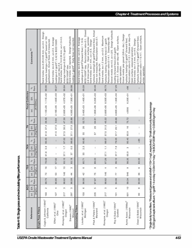
USEPA Onsite Wastewater Treatment Systems Manual 4-53
Chapter 4: Treatment Processes and Systems
Table
4-1
6. S
ingle
pass a
nd re
circula
ting filte
r perform
ance.
a S
ingle
-fam
ily h
om
e filte
rs. b R
est
aura
nt (
gre
ase
and o
il inf/e
ff = 1
19/<
1 m
g/L
resp
ect
ively
). c S
mall c
om
munity
treatin
g a
vera
ge
15,0
00 g
pd o
f septic
tank
effluent.
d 1
gpd/ft
2 =
4 c
m/d
ay
= 0
.04m
3/m
2×day. e 1
lb B
OD
/1000ft2
×day
= 0
.00455 k
g/m
2 ×day

Chapter 4: Treatment Processes and Systems
4-54 USEPA Onsite Wastewater Treatment Systems Manual
Pumps are used to discharge the settled effluent at
the end of the cycle (usually one day). Fixed film
treatment plants typically are operated as continu-
ous flow systems.
Oxygen is transferred by diffused air, sparged
turbine, or surface entrainment devices. When
diffused air systems are used, blowers or compres-
sors are used to force the air through diffusers near
the bottom of the tank. The sparged turbine is
typically designed with a diffused air source and an
external mixer, e.g., a submerged flat-bladed
turbine. The sparged turbine is more complex than
the simple diffused air system. A variety of surface
entrainment devices aerate and mix the wastewater.
Air is entrained and circulated in the mixed liquor
through violent agitation from mixing or pumping.
The separation of process-generated solids by
clarification or filtration is a critical design factor
for successful ATU performance. Most ATUs are
designed to rely on the process of simple gravity
separation to remove most of the solids. Some
systems include effluent filters within the clarifier
to further screen and retain solids in the treatment
plant. Gas deflection barriers and scum baffles are
a part of some designs and are a simple way to
keep floating solids away from the weir area.
Properly managed uplow clarifiers can improve
separation.
4.8.2 Design Considerations
ATU’s are typically rated by hydraulic capacity and
organic and solids loadings. ATU daily treatment
volumes may range from 400 gpd to a maximum
of 1,500 gpd. ATUs typically can be used to treat
residential wastewaters with influent concentrations
which have 100 mg/L to 300 mg/L total organic
compounds and 100 mg/L to 350 mg/L total
suspended solids. Design flows are generally set by
local sanitary codes for residential and commercial
dwellings using methods described in Section 3.3.
ATU’s should be equipped with audio and visual
alarms to warn of compressor/aerator failure and
high water. These alarms alert the owner and/or
service provider of service issues that require
immediate attention.
ATU’s should be constructed of noncorrosive
materials, including reinforced plastics and
fiberglass, coated steel, and reinforced concrete.
Buried ATU’s must be designed to provide easy
access to mechanical parts, electrical control
systems, and appurtenances requiring maintenance
such as weirs, air lift pump lines, etc. ATU’s
installed above ground should be properly housed
to protect against severe climatic conditions.
Installation should be in accordance with manufac-
turers’ specifications.
Appurtenances should be constructed of corrosion-
free materials including polyethylene plastics. Air
diffusers are usually constructed of PVC or ceramic
stone. Mechanical components must be either
waterproofed and/or protected from the elements.
Because blowers, pumps, and other prime movers
can be subject to harsh environments and continu-
ous operation, they should be designed for heavy
duty use. Proper housing can reduce blower noise.
4.8.3 Applications
ATUs are typically integrated in a treatment train to
provide additional treatment before the effluent is
discharged to a SWIS. ATU-treatment trains can
also be designed to discharge to land and surface
waters; ATU discharge is suitable for drip irrigation
if high quality effluent is consistently maintained
through proper management. Although some
jurisdictions allow reductions in vertical separation
distances and/or higher soil infiltration rates when
ATUs are used, consideration must be given to the
potential impacts of higher hydraulic and pollutant
loadings. Increased flow through the soil may
allow deeper penetration of pathogens and
decreased treatment efficiency of other pollutants
(see sections 4.4.2 and 4.4.5).
4.8.4 Performance
Managed ATU effluent quality is typically
characterized as 25 mg/L or less CBOD5 and 30
mg/L or less TSS. Fecal coliform counts are
typically 3-4 log # / 100 ml (Table 3-19) when the
ATUs are operated at or below their design flows
and the influent is typical domestic sewage.
Effluent nutrient levels are dependent on influent
concentrations, climate, and operating conditions.
Other wastewater characteristics may influence
performance. Cleaning agents, bleach, caustic
USEPA Onsite Wastewater Treatment Systems Manual 4-55
Chapter 4: Treatment Processes and Systems
agents, floating matter, and other detritus can plug
or damage equipment. Temperature will affect
process efficiency, i.e., treatment efficiency
generally will improve as the temperature
increases.
Owners should be required by local sanitary codes
or management program requirements to maintain
ongoing service agreements for the life of the
system. ATU’s should be inspected every three
months to help ensure proper operation and
treatment effectiveness. Many ATU manufacturers
offer a two-year warranty with an optional service
agreement after the warranty expires. Inspections
generally include visual checks of hoses, wires,
leads and contacts, testing of alarms, examination
of the mixed liquor, cleaning of filters, removal of
detritus, and inspection of the effluent. ATU’s
should be pumped when the mixed-liquor (aerator)
solids are above 6,000 mg/L or the final settler is
more than 1/3 full of settled solids.
4.8.5 Risk management
ATU’s should be designed to protect the treatment
capability of the soil dispersal system and also to
sound alarms or send signals to the management
entity (owners and/or service providers) when
inspection or maintenance is needed. All biological
systems are sensitive to temperature, power
interruptions, influent variability, and shock
loadings of toxic chemicals. Successful operation
of ATUs depends on adherence to manufacturers’
design and installation requirements and good
management that employs meaningful measure-
ments of system performance at sufficiently
frequent intervals to ascertain changes in system
function. Consistent performance depends on a
stable power supply, an intact system as designed,
and routine maintenance to ensure that components
and appurtenances are in good order. ATU’s, like
all other onsite wastewater treatment technologies,
will fail if they are not designed, installed, or
operated properly. Vigilance on the part of owners
and service providers is essential to ensure ATUs
are operated and maintained to function as
designed.
4.8.6 Costs
Installed ATU costs range from $2500 to $9000
installed. Pumping may be necessary at any time
due to process upsets, or every eight to twelve
months, depending on influent quality, temperature
and type of process. Pumping could cost from
$100-to-$300, depending on local requirements.
Aerators/compressors last about three to five years
and cost from $300 to $500 to replace.
Many communities require service contracts.
These contracts typically range in cost between
$100 and $400 per year, depending on the options
and features the owners choose. The high end
includes pumping costs. Power requirements are
generally quoted at around $200/year.
References
American Society for Testing and Materials
(ASTM). 1993 (pp. 63–65). Standard
Specification for Precast Concrete Septic
Tanks. C 1227. American Society for Testing
and Materials, West Conshohocken, PA.
American Manufacturing. 2001. Alternative
Drainfield. Used with permission. http://
www.americanonsite.com/american/
lit9901.html.
Amerson, R.S., E.J. Tyler, and J.C. Converse.
1991. Infiltration as Affected by Compaction,
Fines and Contact Area of Gravel. In On-Site
Wastewater Treatment: Proceedings of the Sixth
National Symposium on Individual and Small
Community Sewage Systems. American Society
of Agricultural Engineers, St. Joseph, MI.
Anderson, D.L., M.B. Tyl, R.J. Otis, T.G. Mayer,
K.M. Sherman. 1998. Onsite Wastewater
Nutrient Reduction Systems (OWNRS) for
Nutrient Sensitive Environments. In On-Site
Wastewater Treatment: Proceedings of the
Eighth National Symposium on Individual and
Small Community Sewage Systems, ed. D.M.
Sievers. American Society of Agricultural
Engineers, St. Joseph, MI.
Chapter 4: Treatment Processes and Systems
4-56 USEPA Onsite Wastewater Treatment Systems Manual
Anderson, J.L., R.E. Machmeier, and M.P.
Gaffron. 1985. Evaluation and Performance of
Nylon Wrapped Corrugated Tubing in
Minnesota. In On-Site Wastewater Treatment:
Proceedings of the Fourth National Symposium
on Individual and Small Community Sewage
Systems. American Society of Agricultural
Engineers, St. Joseph, MI.
Aqua Test, Inc., and Stuth Co., Inc. 1995. Crushed
Recycled Glass as a Filter Media for the Onsite
Treatment of Wastewater. Washington State
Department of Community, Trade and
Economic Development, Clean Washington
Center, Olympia, WA.
Ayres Associates. 1993. Onsite Sewage Disposal
System Research in Florida: An Evaluation of
Current OSDS Practices in Florida. Report to
the State of Florida Department of Health and
Rehabilitative Services Environmental Health
Program, Tallahassee, FL.
Ayres Associates. 1994. Evaluation of Hydraulic
Loading Criteria for the “Perc-Rite”®
Subsurface Drip Irrigation Systems. Report
prepared for Waste Water Systems, Inc.,
Lilburn, GA.
Ayres Associates. 1996. Contaminant Transport
Investigation from an Onsite Wastewater
Treatment System (OWTS) in Fine Sand.
Phase 3 report to the Soap and Detergent
Association, New York, NY.
Ayres Associates. 1998a. Unpublished data.
Madison, WI.
Ayres Associates. 1998b. Florida Keys Onsite
Wastewater Nutrient Reduction Systems
Demonstration Project—Final Report. Florida
Department of Health, Tallahassee, FL.
Ayres Associates. 1998c. Design memo:
Recirculating sand/gravel filter recirculation
tank design. Unpublished design memo. Ayres
Associates, Madison, WI.
Ayres Associates. 2000 Unpublished graphic.
Madison, WI.
Baumann, E.R., and H.E. Babbit. 1953. An
Investigation of the Performance of Six Small
Septic Tanks. University of Illinois
Engineering Experiment Station. Bulletin
Series No. 409. Vol. 50, No. 47. University of
Illinois, Urbana, IL.
Baumann, E.R., E.E. Jones, W.M. Jakubowski, and
M.C. Nottingham. 1978. Septic Tanks. In
Home Sewage Treatment: Proceedings of the
Second National Home Treatment Symposium.
American Society of Agricultural Engineers,
St. Joseph, MI.
Berkowitz, S.J. 1985. Pressure Manifold Design
for Large Subsurface Ground Absorption
Sewage Systems. In Onsite Wastewater
Treatment: Proceedings of the Fourth National
Symposium on Individual and Small
Community Sewage Systems. American Society
of Agricultural Engineers, St. Joseph, MI.
Berkowitz, S.J., and J.R. Harman. 1994. Computer
Program for Evaluating the Hydraulic Design
of Subsurface Wastewater Drip Irrigation
System Pipe Networks. In On-Site Wastewater
Treatment: Proceedings of the Seventh
International Symposium on Individual and
Small Community Sewage Systems, ed. E.
Collins. American Society of Agricultural
Engineers, St. Joseph, MI.
Boller, M., A. Schweger, J. Eugster, and V. Mettier.
1994. Dynamic behavior of intermittent sand
filters. Water Science and Technology
28(10):98-107.
Bomblat, C., D.C. Wolf, M.A. Gross, E.M.
Rutledge, and E.E. Gbur. 1994. Field
Performance of Conventional and Low
Pressure Distribution Septic Systems. In On-
Site Wastewater Treatment: Proceedings of the
Seventh International Symposium on Individual
and Small Community Sewage Systems, ed. E.
Collins. American Society of Agricultural
Engineers, St. Joseph, MI.
Bouma, J. 1975. Unsaturated flow during soil
treatment of septic tank effluent. Journal of
Environmental Engineering Division, American
Society of Civil Engineers, 101:967-983
Bouma, J., J.C. Converse, and F.R. Magdoff. 1974.
Dosing and resting to improve soil absorption
beds. Transactions, American Society of
Agricultural Engineers, 17:295-298.
Bounds, T.R. 1994. Septic Tank Septage Pumping
Intervals. In On-Site Wastewater Treatment:
USEPA Onsite Wastewater Treatment Systems Manual 4-57
Chapter 4: Treatment Processes and Systems
Proceedings of the Seventh International
Symposium on Individual and Small
Community Sewage Systems, ed. E. Collins.
American Society of Agricultural Engineers,
St. Joseph, MI.
Bowne, W.C. 1982. Characteristics and Treatment
of STEP Pressure Sewer Collected Wastewater.
Draft report submitted to U.S. Environmental
Protection Agency, Cincinnati, OH.
Boyle, W.C., R.J. Otis, R.A. Apfel, R.W.
Whitmyer, J.C. Converse, B.Burkes, M.J.
Bruch, Jr., and M. Anders. 1994. Nitrogen
Removal from Domestic Wastewater in
Unsewered Areas. In On-Site Wastewater
Treatment: Proceedings of the Seventh
International Symposium on Individual and
Small Community Sewage Systems. American
Society of Agricultural Engineers, St. Joseph,
MI.
Boyer, J.A., and C.A. Rock. 1992. Performance of
Septic Tanks. In Proceedings, ed. R.W.
Seabloom, Seventh Northwest On-Site
Wastewater Treatment Short Course and
Equipment Exhibition, University of
Washington, Seattle.
Brandes, M. 1977. Accumulation Rate and
Characteristics of Septic Tank Sludge and
Septage. Ontario MOE Report No. W63.
Toronto, ON, Canada.
Brown, D.F., L.A. Jones, and L.S. Wood. 1994. A
Pedologic Approach for Siting Wastewater
Systems in Delaware. In Proceedings of the
Seventh National Symposium on Individual and
Small Community Sewage Systems, pp. 229-
237. American Society of Agricultural
Engineers, St. Joseph, MI.
Brown, K.W., J.F. Slowey, and H.W. Wolf. 1977.
Accumulation and Passage of Pollutants in
Domestic Septic Tank Disposal Fields. Final
report submitted to U.S. Environmental
Protection Agency. Project no. R801955-01-2.
Texas A&M Research Foundation, College
Station, TX.
Buzzards Bay Project, Massachusetts Alternative
Septic System Test Center, Buzzards Bay
Project National Estuary Program. http://
www.buzzardsbay.org/eti.htm
Cagle, W.A., and L.A. Johnson. 1994. On-site
Intermittent Sand Filter Systems, a Regulatory/
Scientific Approach to Their Study in Placer
County, California. In On-Site Wastewater
Treatment: Proceedings of the Seventh
International Symposium on Individual and
Small Community Sewage Systems. American
Society of Agricultural Engineers, St. Joseph,
MI.
Camp, G.N., Jr. 1985. Seasonal Variation of Two-
Dimensional Flow from a Wastewater Disposal
Trench. M.S. thesis, University of Cincinnati,
Cincinnati, OH.
Carlile, B.L., and D.J. Osborne. 1982. Some
experience with gravel-less systems in Texas
coastal areas. In On-Site Sewage Treatment:
Proceedings of the Third National Symposium
on Individual and Small Community Sewage
Treatment. American Society of Agricultural
Engineers, St. Joseph, MI.
Colorado School of Mines. 2001. Letter report
summarizing the field evaluations of virus
treatment efficiency by wastewater soil
absorption systems with aggregate-free and
aggregate-laden infiltration surfaces. Lowe,
VanCuyk, Dodson, and Siegrist.
Converse, J.C. 1974. Distribution of domestic
waste effluent in soil absorption beds.
Transactions, American Society of Agricultural
Engineers, 17:299-309.
Converse, James C. 1997, 1999, 2000, 2001.
Aeration Treatment of Onsite Domestic
Wastewater Aerobic Units and Packed Bed
Filters, University of Wisconsin-Madison.
Converse, J.C., and R.J. Otis. 1982. Field
Evaluation of Pressure Distribution Networks.
In Onsite Wastewater Treatment: Proceedings of
the Third National Symposium on Individual
and Small Community Sewage Systems. ASAE
Publication 1-82, American Society of
Agricultural Engineers, St. Joseph, MI.
Converse, J.C. and E.J. Tyler. 1998a. Soil Dispersal
of Highly Pretreated Effluent – Considerations
for Incorporation into Code. In Proceedings:
Seventh Annual Conference and Exhibit.
National Onsite Wastewater Recycling
Association, Northbrook, IL.
Chapter 4: Treatment Processes and Systems
4-58 USEPA Onsite Wastewater Treatment Systems Manual
Converse, J.C., and E.J. Tyler. 1998b. Soil
treatment of aerobically treated domestic
wastewater with emphasis on modified
mounds. In On-Site Wastewater Treatment:
Proceedings of the Eighth National Symposium
on Individual and Small Community Sewage
Systems, ed. D.M. Sievers. American Society
of Agricultural Engineers, St. Joseph, MI.
Converse, J.C., and E.J. Tyler. 2000. Wisconsin
Mound Soil Absorption System: Siting, Design,
and Construction Manual. Small Scale Waste
Management Project, University of Wisconsin-
Madison, Madison, WI.
Converse, J.C., E.J. Tyler, and J.O. Peterson. 1990.
Wisconsin At-Grade Soil Absorption System:
Siting, Design, and Construction Manual.
Small Scale Waste Management Project,
University of Wisconsin-Madison, Madison.
Council of State Governments. 1998. Getting In
Step: A Guide to Effective Outreach in Your
Watershed. CSG Environmental Policy Group,
Lexington, KY. <http://www.epa.gov/owow/
watershed/outreach/documentes/>.
Crites, R., and G. Tchobanoglous. 1998. Small and
Decentralized Wastewater Management
Systems. McGraw-Hill, San Francisco, CA.
Darby, J., G. Tchobanoglous, M.A. Nor, and D.
Maciolek. 1996. Shallow intermittent sand
filtration performance evaluation. Small Flows
Journal 2(1):3-15.
Duncan, C.S., R.B. Reneau, Jr., and C. Hagedorn.
1994. Impact of Effluent Quality and Soil
Depth on Renovation of Domestic Wastewater.
In On-Site Wastewater Treatment: Proceedings
of the Seventh International Symposium on
Individual and Small Community Sewage
Systems, ed. E. Collins. American Society of
Agricultural Engineers, St. Joseph, MI.
Effert, D., and M. Cashell. 1987. A Comparative
Study of Three Soil Absorption Trench
Designs Installed in an Illinoian Till Soil. In
On-Site Wastewater Treatment: Proceedings of
the Fifth National Symposium on Individual
and Small Sewage Systems. American Society
of Agricultural Engineers, St. Joseph, MI.
Effert, D., J. Morand, and M. Cashell. 1985. Field
Performance of Three Onsite Effluent Polshing
Units. In On-Site Wastewater Treatment:
Proceedings of the Fourth National Symposium
on Individual and Small Community Sewage
Systems. American Society of Agricultural
Engineers, St. Joseph, MI.
Emerick, R.W., R.M. Test, G. Tchohanglous, and
J. Darby. 1997. Shallow Intermittent Sand
Filtration: Microorganism Removal. Small
Flows Journal 3(1):12-22.
Erickson, Jenny, E.J. Tyler. 2001. A Model for Soil
Oxygen Delivery to Wastewater Infiltration
Surfaces. In On-Site Wastewater Treatment:
Proceedings of the Ninth National Symposium
on Individual and Small Community Sewage
Systems. American Society of Agricultural
Engineers, St. Joseph, MI.
Fiege, W.A., E.T. Oppett, and J.F. Kreissl. 1975.
An Alternative Septage Treatment Method:
Lime Stabilization/Sand-Bed Dewatering. EPA-
600/2-75-036. U.S. Environmental Protection
Agency, Washington, DC.
Geoflow, Inc. 1999. Design, Installation &
Maintenance Manual—Small Systems.
Geoflow, Inc., Charlotte, NC.
Gross, M.A., P.R. Owens, N.D. Dennis, A.K.
Robinson, E.M. Rutledge. 1998. Sizing Onsite
Wastewater Systems Using Soil Characteristics
as Compared to the Percolation Test. In On-
Site Sewage Treatment: Proceedings of the
Eighth National Symposium on Individual and
Small Community Sewage Treatment. American
Society of Agricultural Engineers, St. Joseph,
MI.
Hargett, D.L., E.J. Tyler, and R.L. Siegrist. 1982.
Soil Infiltration Capacity as Affected by Septic
Tank Effluent Application Strategies. In On-
Site Sewage Treatment: Proceedings of the
Third National Symposium on Individual and
Small Community Sewage Treatment. American
Society of Agricultural Engineers, St. Joseph,
MI.
Hines, M., and R.E. Favreau. 1974. Recirculating
Sand Filters: An Alternative to Traditional
Sewage Absorption Systems. In Home Sewage
Disposal: Proceedings of the National Home
Sewage Disposal Symposium. American Society
of Agricultural Engineers, St. Joseph, MI.
USEPA Onsite Wastewater Treatment Systems Manual 4-59
Chapter 4: Treatment Processes and Systems
Hinson, T.H., M.T. Hoover, and R.O. Evans. 1994.
Sand-lined Trench Septic System Performance
on Wet, Clayey Soils. In Proceedings of the
Seventh International Symposium on Individual
and Small Community Sewage Systems, pp.245-
255. American Society of Agricultural
Engineers, St. Joseph, MI.
Hoover, M.T., A. Amoozegar, and D. Weymann.
1991. Performance assessment of sand filter,
low pressure pipe systems in slowly permeable
soils of Triassic Basin. In Proceedings of Sixth
National Symposium on Individual and Small
Community Sewage Systems, pp. 324-337.
American Society of Agricultural Engineers,
St. Joseph, MI.
Hoover, M.T., T.M. Disy, M.A. Pfeiffer, N.
Dudley, R.B. Meyer, and B. Buffington. 1996.
North Carolina Subsurface Operators Training
School Manual. Soil Science Department,
College of Agriculture and Life Sciences,
North Carolina State University, Raleigh, NC,
and North Carolina Department of
Environment, Health and Natural Resources,
Raleigh, NC.
International Code Council (ICC). 1995.
International Private Sewage Disposal Code.
International Code Council, Inc.
Jones, E.E. 1975. Domestic Water Use in
Individual Homes and Hydraulic Loading and
Discharge from Septic Tanks. In Home Sewage
Disposal: Proceedings of the First National
Home Sewage Disposal Symposium. American
Society of Agricultural Engineers, St. Joseph,
MI.
Jones, J.H., and G.S. Taylor. 1965. Septic tank
effluent percolation through sands under
laboratory conditions. Soil Science 99:301-309.
Keys, J.R., E.J. Tyler, and J.C. Converse. 1998.
Predicting Life for Wastewater Absorption
Systems. In On-Site Wastewater Treatment:
Proceedings of the Eighth National Symposium
on Individual and Small Community Sewage
Systems, ed. D.M. Sievers. American Society
of Agricultural Engineers, St. Joseph, MI.
Kinnicutt, L.P., C.E.A. Winslow, and R.W. Pratt.
1910. Sewage Disposal. John Wiley & Sons,
New York.
Kleiss, H.J. and M.T. Hoover. 1986. Soil and Site
Criteria for On-site Systems. In Utilization,
Treatment, and Disposal of Waste on Land. Soil
Science society of America, Madison, WI.
Laak, R. 1976. Influence of domestic wastewater
pretreatment on soil clogging. Journal of Water
Pollution Control Federation 42(Part 1):1495-
1500.
Laak, R. 1986. Wastewater Engineering Design for
Unsewered Areas. 2nd ed. Technomic
Publishing Co., Inc., Lancaster, PA.
Levine, A.D., G. Tchohanoglous, and T. Asano.
1991. Size distributions of particulate
contaminants in wastewater and their impacts
on treatability. Water Research 25(8):911-922.
Lombardo, Pio. 2000. Onsite Wastewater
Treatment System Graphics. Lombardo
Associates, Newton, MA. <http://
www.lombardoassociates.com>.
Loomis, G.W., D.B. Dow, M.H. Stolt, A.D. Sykes,
A.J. Gold. 2001. Performance Evaluation of
Innovative Treatment Technologies Used to
Remediate Failed Septic Systems. In Onsite
Wastewater Treatment: Proceedings of the
Ninth National Symposium on Individual and
Small Community Sewage Systems. American
Society of Agricultural Engineers, St. Joseph,
MI.
Louden, T.L., D.B. Thompson, L. Fay, and L.E.
Reese. 1985. Cold climate performance of
recirculating sand filters. In On-Site
Wastewater Treatment: Proceedings of the
Fourth National Symposium on Individual and
Small Community Sewage Systems. American
Society of Agricultural Engineers, St. Joseph,
MI.
Louden, T.L., G.S. Salthouse, and D.L. Mokma.
1998. Wastewater Quality and Trench System
Design Effects on Soil Acceptance Rates.
Onsite Wastewater Treatment: Proceedings of
the Eighth National Symposium on Individual
and Small Community Sewage Systems.
American Society of Agricultural Engineers,
St. Joseph, MI.
Ludwig, H.F. 1950. Septic tanks—Design and
performance. Sewage and Industrial Wastes
96:122.
Chapter 4: Treatment Processes and Systems
4-60 USEPA Onsite Wastewater Treatment Systems Manual
Mancl, K.M. 1998. Septic Tank Maintenance. Ohio
State University Extension Fact Sheet AEX-
740-98. Ohio State University, Food,
Agricultural and Biological Engineering,
Columbus, OH.
McGauhey, P., and J.T. Winneberger. 1964. Studies
of the failure of septic tank percolation
systems. Journal Water Pollution Control
Federation 36:593-606.
Mokma, D.L., T.L. Loudon, P. Miller. 2001.
Rationale for Shallow Trenches in Soil
Treatment Systems. In On-Site Sewage
Treatment: Proceedings of the Ninth National
Symposium on Individual and Small
Community Sewage Treatment. American
Society of Agricultural Engineers, St. Joseph,
MI.
Mote, C.R. 1984. Pressurized Distribution for On-
Site Domestic Wastewater-Renovation Systems.
Bulletin 870. Agricultural Experiment Station,
University of Arkansas, Fayetteville, AR.
Mote, C.R., J.W. Pote, E.M. Rutledge, H.D. Scott,
and D.T. Mitchell. 1981. A computerized
design and simulation model for pressure
distribution systems in sloping septic tank filter
fields. In On-Site Sewage Treatment:
Proceedings of the Third National Symposium
on Individual and Small Community Sewage
Treatment. American Society of Agricultural
Engineers, St. Joseph, MI.
National Small Flows Clearinghouse. Winter, 1996.
Pipeline: Small Community Wastewater Issues
Explained to the Public. Vol. 7 no. 1.
National Small Flows Clearinghouse. 2000.
National Environmental Service Center. West
Virginia University. Morgantown, WV.
Noland, R.F., J.D. Edwards, and M. Kipp. 1978.
Full-Scale Demonstration of Lime
Stabilization. EPA-600/2-78-171. U.S.
Environmental Protection Agency, Office of
Research and Development, Cincinnati, OH.
North Carolina Department of Environment,
Health, and Natural Resources (DEHNR).
1996. On-Site Wastewater Management
Guidance Manual. North Carolina Department
of Environment, Health, and Natural
Resources, Division of Environmental Health,
On-Site Wastewater Section, Raleigh, NC.
NPCA. 1998. Septic Tank Manufacturing—Best
Practices Manual. National Precast Concrete
Association, Indianapolis, IN. <http://
www.precast.org>
Otis, R.J. 1978. An Alternative Public Wastewater
Facility for a Small Rural Community. Small
Scale Waste Management Project. University of
Wisconsin-Madison, Madison, WI.
Otis, R.J. 1982. Pressure distribution design for
septic tank systems. Journal of the
Environmental Engineering Division, American
Society of Civil Engineers, 108(EE1): 123-
140.
Otis, R.J. 1985. Soil Clogging: Mechanisms and
Control. In On-Site Wastewater Treatment:
Proceedings of the Fourth National Symposium
on Individual and Small Community Sewage
Systems. American Society of Agricultural
Engineers, St. Joseph, MI.
Otis, R.J. 1985. Soil Clogging: Mechanisms and
Control. In Onsite Wastewater Treatment:
Proceedings of the Fourth National Symposium
on Individual and Small Community Sewage
Systems. American Society of Agricultural
Engineers, St. Joseph, MI.
Otis, R.J. 1997. Considering reaeration. In
Proceedings: Ninth Northwest On-Site
Wastewater Treatment Short Course and
Equipment Exhibition, ed. R.W. Seabloom.
University of Washington, Seattle, WA.
Otis, R.J. 2001. Boundary Design: A Strategy for
Subsurface Wastewater Infiltration System
Design and Rehabilitation. In On-Site
Wastewater Treatment: Proceedings of the
Ninth National Symposium on Individual and
Small Community Sewage Systems. American
Society of Agricultural Engineers, St. Joseph,
MI.
Otis, R.J., J.C. Converse, B.L. Carlile, and J.E.
Witty. 1977. Effluent Distribution. In Home
Sewage Treatment: Proceedings of the Second
National Home Sewage Treatment Symposium.
American Society of Agricultural Engineers,
St. Joseph, MI.
USEPA Onsite Wastewater Treatment Systems Manual 4-61
Chapter 4: Treatment Processes and Systems
Otis, R.J., J.C. Converse, B.L. Carlile, J.E. Witty.
1978. Effluent Distribution. In On-Site
Wastewater Treatment: Proceedings of the
Second National Symposium on Individual and
Small Community Sewage Systems. American
Society of Agricultural Engineers, St. Joseph,
MI.
Owen, J.E., and K.L. Bobb. 1994. Winter
Operation and Performance of a Recirculating
Sand Filter. In: Proceedings: WEFTEC’94, 67th
Annual Conference and Exposition. Water
Environment Federation, Alexandria, VA.
Pell, M., and F. Nyberg. 1989. Infiltration of
wastewater in a newly started pit sand filter
system. Journal of Environmental Quality
18(4):451-467.
Penninger, P.G., and M.T. Hoover. 1998.
Performance of an at-grade septic system
preceded by a pressure-dosed sand filter on a
wet, clayey slate belt soil. In On-Site
Wastewater Treatment: Proceedings of the
Eighth National Syposium on Individual and
Small Community Sewage Systems, ed. D.M.
Sievers, pp. 326-335. American Society of
Agricultural Engineers, St. Joseph, MI.
Piluk, R.J. 1998. Maintenance of small
recirculating sand filters. In Proceedings:
Seventh Annual Conference and Exhibit.
National Onsite Wastewater Recycling
Association, Northbrook, IL.
Piluk, R.J., and E.C. Peters. 1994. Small
recirculating sand filters for individual homes.
In On-Site Wastewater Treatment: Proceedings
of the Seventh International Symposium on
Individual and Small Community Sewage
Systems. American Society of Agricultural
Engineers, St. Joseph, MI.
Purdue University. 1990a. Steps in Constructing a
Mound (Bed-Type) Septic System. Cooperative
Extension Service, Purdue University, West
Lafayette, IN.
< http://www.agcom.purdue.edu/AgCom/Pubs/
ID/ID-163.html>.
Purdue University. 1990b. Construction Guidelines
for Conventional Systems. Cooperative
Extension Service, Purdue University, West
Lafayette, IN. <http://www.agcom.purdue.edu/
~agcom/Pubs/ID/ID-170.html>.
Robeck, G.C., T.W. Bendixen, W.A. Schwartz, and
R.L. Woodward. 1964. Factors influencing the
design and operation of soil systems for waste
treatment. Journal Water Pollution Control
Federation 36:971-983. Alexandria, VA.
Robertson, W.D., and J. Harman. 1999. Phosphate
plume persistence at two decommissioned
septic system sites. Ground Water 37:228-236.
Robertson, W.D., J.A. Cherry, and E.A. Sudicky.
1989. Ground water contamination at two
small septic systems on sand aquifers. Ground
Water 29:82-92.
Robertson, W.D., S.L. Schiff, and C.J. Ptacek.
1998. Review of phosphate mobility and
persistence in 10 septic system plumes. Ground
Water 36: 100-110.
Ronayne, M.P., R.C. Paeth, and S.A. Wilson. 1982.
Oregon On-Site Experimental Systems Program.
Final report to U.S. Environmental Protection
Agency. Project No. 5806349. Oregon
Department of Environmental Quality, Salem,
OR.
Rose, J.B., D.W. Griffin, and L.W. Nicosia. 1999.
Virus Transport From Septic Tanks to Coastal
Waters. In Proceedings of the Tenth Northwest:
Onsite Wastewater Treatment Short Course and
Equipment Exhibition. University of
Washington, Seattle, WA.
Roy, C., and J.P. Dube. 1994. A recirculating
gravel filter for cold climates. In On-Site
Wastewater Treatment: Proceedings of the
Seventh International Symposium on Individual
and Small Community Sewage Systems.
American Society of Agricultural Engineers,
St. Joseph, MI.
Schultheis, R.A. 1997. Septic Tank/Soil Absorption
Field Systems: A Homeowner’s Guide to
Installation and Maintenance. University of
Missouri Cooperative Extension Service, Water
Quality Initiative Publication WQ 401. Revised
March 15, 1997.
Shaw, B., and N.B. Turyk. 1994. Nitrate-N loading
to ground water from pressurized mound, in-
ground and at-grade septic systems. In On-Site
Wastewater Treatment: Proceedings of the
Seventh International Symposium on Individual
and Small Community Sewage Systems, ed.

Chapter 4: Treatment Processes and Systems
4-62 USEPA Onsite Wastewater Treatment Systems Manual
E.Collins. American Society of Agricultural
Engineers, St. Joseph, MI.
Siegrist, R.L., and W.C. Boyle. 1987. Wastewater-
induced soil clogging development. Journal of
Environmental Engineering, American Society
of Civil Engineering, 113(3):550-566.
Siegrist, R.L., D.L. Anderson, and J.C. Converse.
1985. Commercial wastewater on-site treatment
and disposal. In On-Site Wastewater Treatment:
Proceedings of the Fourth National Symposium
on Individual and Small Community Sewage
Systems. American Society of Agricultural
Engineers, St. Joseph, MI.
Siegrist, R.L., D.L. Anderson, and D.L. Hargett.
1986. Large Soil Absorption Systems for
Wastewaters from Multiple-Home
Developments. EPA/600/S2-86/023. U.S.
Environmental Protection Agency, Cincinnati,
OH.
Siegrist, R.L., E.J. Tyler, and P.D. Jenssen. 2000.
Design and Performance of Onsite Wastewater
Soil Absorption Systems. In Risk-Based
Decision Making for Onsite Wastewater
Treatment: Proceedings of the Research Needs
Conference. National Decentralized Water
Resources Capacity Development Project. U.S.
Environmental Protection Agency, Cincinnati,
OH. (In press).
Siegrist, R.L., and S. Van Cuyk. 2001a. Wastewater
Soil Absorption Systems: The Performance
Effects of Process and Environmental
Conditions. In On-Site Wastewater Treatment:
Proceedings of the Ninth National Symposium
on Individual and Small Community Sewage
Systems. American Society of Agricultural
Engineers, St. Joseph, MI.
Siegrist, R.L., and S. Van Cuyk. 2001b. Pathogen
Fate in Wastewater Soil Absorption Systems as
Affected by Effluent Quality and Soil
Clogging Genesis. In On-Site Wastewater
Treatment: Proceedings of the Ninth National
Symposium on Individual and Small
Community Sewage Systems. American Society
of Agricultural Engineers, St. Joseph, MI.
Sievers, D.M. 1998. Pressurized Intermittent Sand
Filter with Shallow Disposal Field for a Single
Residence in Boone County, Missouri. In On-
Site Wastewater Treatment: Proceedings of the
Eighth National Symposium on Individual and
Small Community Sewage Systems. American
Society of Agricultural Engineers, St. Joseph,
MI.
Simon, J.J., and R.B. Reneau, Jr. 1987.
Recommended Septic Tank Effluent Loading
Rates for Fine-Textured, Structured Soils with
Flow Restrictions. In On-Site Wastewater
Treatment: Proceedings of the Sixth National
Symposium on Individual and Small
Community Sewage Systems. American Society
of Agricultural Engineers, St. Joseph, MI.
Solomon, C., P. Casey, C. Mackne, and A. Lake.
1998. Recirculating sand filters. ETI project
for U.S. Environmental Protection Agency,
Office of Wastewater Management. National
Small Flows Clearinghouse.
Tofflemire, T.J., and M. Chen. 1977. Phosphate
removal by sands and soils. Ground water, Vol.
15, p. 377.
Tomson, M., C. Curran, J.M. King, H. Wangg, J.
Dauchy, V. Gordy, and B.A. Ward. 1984.
Characterization of Soil Disposal System
Leachates. EPA/600/2-84/101. U.S.
Environmental Protection Agency, Washington,
DC.
Tyler, E.J. 2000. Unpublished paper. University of
Wisconsin-Madison, Department of Soil
Science, Madison, WI.
Tyler, E.J., W.C. Boyle, J.C. Converse, R.L.
Siegrist, D.L. Hargett, and M.R.
Schoenemann. 1985. Design and Management
of Subsurface Soil Absorption Systems, EPA/
600/2-85/070. U.S. Environmental Protection
Agency, Water Engineering Research
Laboratory, Cincinnati, OH.
Tyler, E.J., and J.C. Converse. 1994. Soil
acceptance of onsite wastewater as affected by
soil morphology and wastewater quality. In
Proceedings of the 7th National Symposium on
Individual and Small Community Sewage
Systems, pp. 185-194. American Society of
Agricultural Engineers, St. Joseph, MI.
Tyler, E.J., E.M. Drozd, and J.O. Peterson. 1991.
Hydraulic Loading Based Upon Wastewater
Effluent Quality. In On-Site Wastewater
Treatment: Proceedings of the Sixth National
USEPA Onsite Wastewater Treatment Systems Manual 4-63
Chapter 4: Treatment Processes and Systems
Symposium on Individual and Small
Community Sewage Systems. American Society
of Agricultural Engineers, St. Joseph, MI
University of Wisconsin. 1978. Management of
Small Waste Flows. EPA-600/2-78-173. U.S.
Environmental Protection Agency, Cincinnati,
OH.
U.S. Department of Agriculture (USDA). 1973.
Drainage of Agricultural Land. U.S.
Department of Agriculture, Soil Conservation
Service, Water Information Center.
U.S. Environmental Protection Agency (USEPA).
1980. Design Manual: Onsite Wastewater
Treatment and Disposal Systems. EPA 625/1-
80-012. Office of Water Programs, Office of
Research and Development, Washington, DC.
U.S. Environmental Protection Agency (USEPA).
1991. Manual: Alternative Wastewater
Collection Systems. Technical Report. EPA
625/1-91/024. Office of Research and
Development. Cincinnati, OH.
U.S. Environmental Protection Agency (USEPA).
1992. Manual: Treatment/Disposal for Small
Communities. EPA 625/R-92/005. U.S.
Environmental Protection Agency, Cincinnati,
OH.
U.S. Environmental Protection Agency (USEPA).
1993. Domestic Septage Regulatory Guidance.
EPA 832-B-92-005. U.S. Environmental
Protection Agency, Office of Water,
Washington, DC.
U.S. Environmental Protection Agency (USEPA).
1994. Guide to Septage Treatment and
Disposal. EPA 625/R-94/002. U.S.
Environmental Protection Agency, Office of
Research and Development, Washington, DC.
U.S. Environmental Protection Agency (USEPA).
1995a. Process Design Manual: Land
Application of Sewage Sludge and Domestic
Septage. U.S. Environmental Protection
Agency, Office of Research and Development,
Washington, DC. EPA 625/R-95/001.
U.S. Environmental Protection Agency (USEPA).
1995b. Process Design Manual: Surface
Disposal of Sewage Sludge and Domestic
Septage. EPA/625/K-95/002. September. U.S.
Environmental Protection Agency, Office of
Research and Development, Washington DC.
U.S. Environmental Protection Agency (USEPA).
1999. Environmental Regulation and
Technology: Control of Pathogens and Vector
Attraction in Sewage Sludge. EPA /625/R-92/
013. U.S. Environmental Protection Agency,
Office of Research and Development,
Cincinnati, OH.<http://www.epa.gov/ORD/
NRMRL>.
U.S. Environmental Protection Agency (USEPA),
Office of Water. September, 2000.
Decentralized Systems Technology Fact Sheet:
Aerobic Treatment. EPA/832/00/031.
U.S. Environmental Protection Agency (USEPA).
2000. Guidelines for Management of Onsite/
Decentralized Wastewater Systems (Draft).
U.S. Environmental Protection Agency, Office
of Wastewater Management. Federal Register,
October 6, 2000. <http://www.epa.gov/owm/
smallc/guidelines.htm>.
U.S. Public Health Service (USPHS). 1967.
Manual of Septic Tank Practice. U.S. Public
Health Service Publication No. 526.
Water Environment Federation (WEF). 1990.
Natural Systems of Wastewater Treatment.
Manual of Practice FD-16. Water Environment
Federation, Alexandria, VA.
Weibel, S.R., C.P. Straub, and J.R. Thoman. 1949.
Studies in Household Sewage Disposal Systems.
Part I. Federal Security Agency, Public Health
Service, Robert A. Taft Engineering Center,
Cincinnati, OH.
Weibel, S.R., T.W. Bendixen, and J.B. Coulter.
1954. Studies on Household Sewage Disposal
Systems. Part III. Department of Health,
Education, and Welfare, Public Health Service,
Robert A. Taft Sanitary Engineering Center,
Cincinnati, OH.
Weymann, D.F., A. Amoozegar, and M.T. Hoover.
1998. Performance of an on-site wastewater
disposal system in a slowly permeable soil. In
On-Site Wastewater Treatment: Proceedings of
the Eighth National Syposium on Individual
and Small Community Sewage Systems, ed.
D.M. Sievers, pp. 134-145. American Society
of Agricultural Engineers, St. Joseph, MI.

Chapter 4: Treatment Processes and Systems
4-64 USEPA Onsite Wastewater Treatment Systems Manual
Yates, M.V., and S.R. Yates. 1988. Modeling
microbial fate in the subsurface environment.
Critical Reviews in Environmental Science,
CCECAU 17(4):307-344.

USEPA Onsite Wastewater Treatment Systems Manual 4-65
Chapter 4: Treatment Processes and Systems