washing machine service manual -...
TRANSCRIPT
100
WASHING MACHINESERVICE MANUAL READ THIS MANUAL CAREFULLY TO DIAGNOSE PROBLEMS CORRECTLY BEFORE SERVICING THE UNIT.
MODEL : WM2411HW / WM2011 HSWM2011HW / WM1811CWWM2432HW / WM2032 HSWM2032HW / WM1832CW
CAUTION
Website:http://www.LGEservice.comE-mail:http://www.LGEservice.com/techsup.html
CONTENTS
1. SPECIFICATIONS .........................................................................................................................3
2. FEATURES & TECHNICAL EXPLANATION ................................................................................ 4
3. PARTS IDENTIFICATION ............................................................................................................ 6
4. INSTALLATION............................................................................................................................. 7
5. OPERATION ................................................................................................................................10
6. WIRING DIAGRAM / PROGRAM CHART...................................................................................13
7. TROUBLESHOOTING.................................................................................................................15
7-1. BEFORE PERFORMING SERVICE ...................................................................................15
7-2. QC TEST MODE.................................................................................................................15
7-3. HOW TO CHECK THE WATER LEVEL FREQUENCY ......................................................15
7-4. ERROR DISPLAY ...............................................................................................................16
8. ERROR DIAGNOSIS AND CHECK LIST ....................................................................................18
8-1. DIAGNOSIS AND SOLUTION FOR ABNORMAL OPERATION ........................................18
8-2. FAULT DIAGNOSIS AND TROUBLESHOOTING ..............................................................21
9. DISASSEMBLY INSTRUCTIONS ...............................................................................................28
10. EXPLODED VIEW .....................................................................................................................36
10-1. CABINET & CONTROL PANEL ASSEMBLY....................................................................36
10-2. DRUM & TUB ASSEMBLY................................................................................................37
10-3. DISPENSER ASSEMBLY .................................................................................................38
3
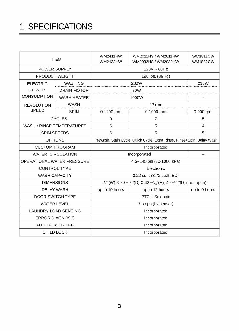
1. SPECIFICATIONS
ITEMWM2411HW WM2011HS / WM2011HW WM1811CWWM2432HW WM2032HS / WM2032HW WM1832CW
POWER SUPPLY 120V ~ 60Hz
PRODUCT WEIGHT 190 lbs. (86 kg)
WASHING 280W 235W
DRAIN MOTOR 80W
WASH HEATER 1000W -
WASH 42 rpm
SPIN 0-1200 rpm 0-1000 rpm 0-900 rpm
CYCLES 9 7 5
WASH / RINSE TEMPERATURES 6 5 4
SPIN SPEEDS 6 5 5
OPTIONS Prewash, Stain Cycle, Quick Cycle, Extra Rinse, Rinse+Spin, Delay Wash
CUSTOM PROGRAM Incorporated
WATER CIRCULATION Incorporated -
OPERATIONAL WATER PRESSURE 4.5-145 psi (30-1000 kPa)
CONTROL TYPE Electronic
WASH CAPACITY 3.22 cu.ft (3.72 cu.ft.IEC)
DIMENSIONS 27”(W) X 29-1/2”(D) X 42-3/4”(H), 49-4/5”(D, door open)
DELAY WASH up to 19 hours up to 12 hours up to 9 hours
DOOR SWITCH TYPE PTC + Solenoid
WATER LEVEL 7 steps (by sensor)
LAUNDRY LOAD SENSING Incorporated
ERROR DIAGNOSIS Incorporated
AUTO POWER OFF Incorporated
CHILD LOCK Incorporated
ELECTRIC
POWER
CONSUMPTION
REVOLUTION SPEED
4
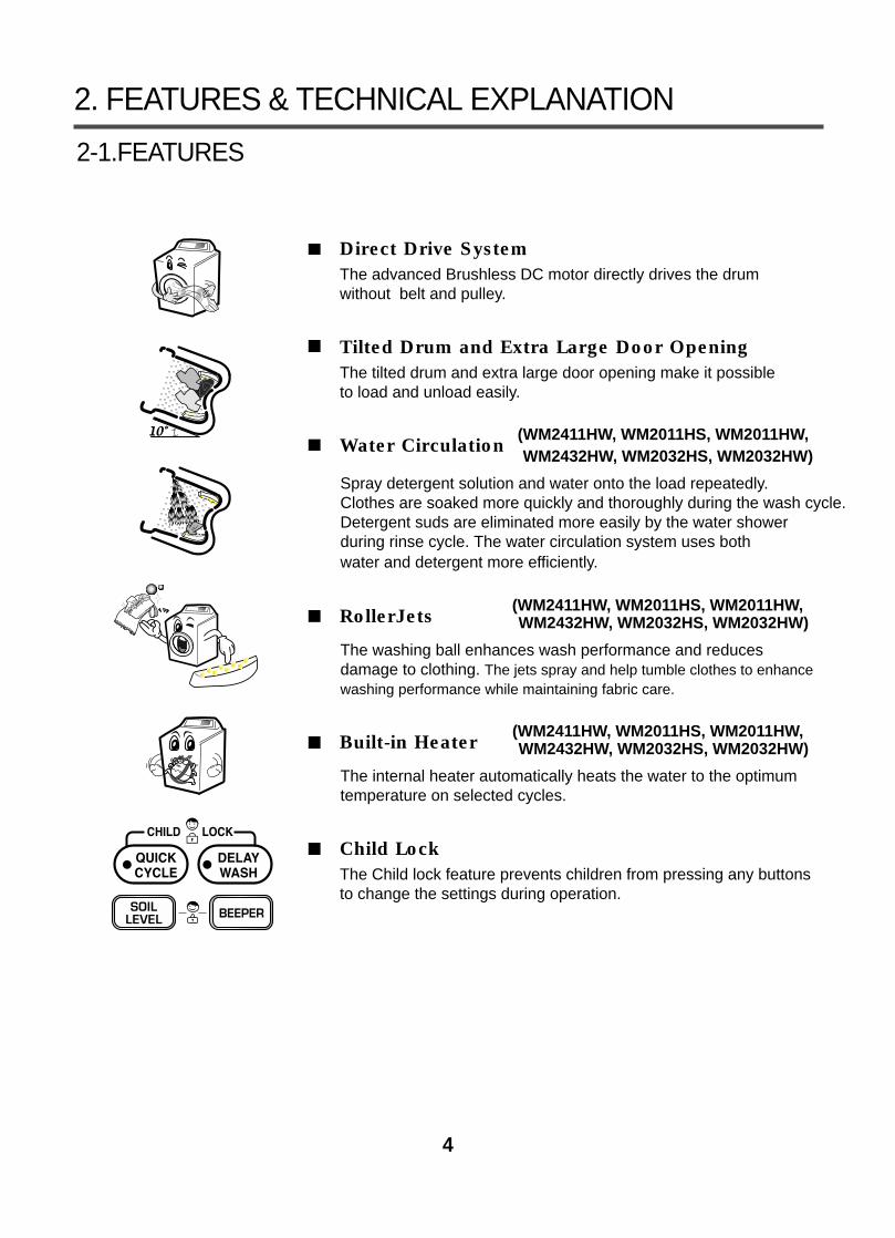
2. FEATURES & TECHNICAL EXPLANATION
2-1.FEATURES
Direct Drive SystemThe advanced Brushless DC motor directly drives the drum without belt and pulley.
Tilted Drum and Extra Large Door OpeningThe tilted drum and extra large door opening make it possible to load and unload easily.
Water Circulation (WM2411HW, WM2011HS, WM2011HW,WM2432HW, WM2032HS, WM2032HW)
Spray detergent solution and water onto the load repeatedly. Clothes are soaked more quickly and thoroughly during the wash cycle. Detergent suds are eliminated more easily by the water shower during rinse cycle. The water circulation system uses both water and detergent more efficiently.
RollerJets (WM2411HW, WM2011HS, WM2011HW,WM2432HW, WM2032HS, WM2032HW)
The washing ball enhances wash performance and reduces damage to clothing. The jets spray and help tumble clothes to enhancewashing performance while maintaining fabric care.
Built-in Heater (WM2411HW, WM2011HS, WM2011HW,WM2432HW, WM2032HS, WM2032HW)
The internal heater automatically heats the water to the optimumtemperature on selected cycles.
Child LockThe Child lock feature prevents children from pressing any buttons to change the settings during operation.
5
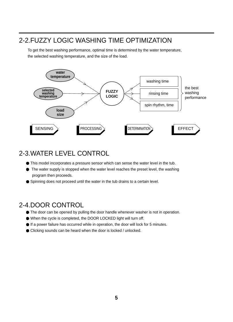
2-2.FUZZY LOGIC WASHING TIME OPTIMIZATIONTo get the best washing performance, optimal time is determined by the water temperature,
the selected washing temperature, and the size of the load.
2-3.WATER LEVEL CONTROLThis model incorporates a pressure sensor which can sense the water level in the tub.
The water supply is stopped when the water level reaches the preset level, the washing
program then proceeds.
Spinning does not proceed until the water in the tub drains to a certain level.
2-4.DOOR CONTROLThe door can be opened by pulling the door handle whenever washer is not in operation.
When the cycle is completed, the DOOR LOCKED light will turn off.
If a power failure has occurred while in operation, the door will lock for 5 minutes.
Clicking sounds can be heard when the door is locked / unlocked.
FUZZYLOGIC
loadsize
selectedwashing
temperature
watertemperature
washing time
rinsing time
spin rhythm, time
the bestwashingperformance
SENSING PROCESSING DETERMINATION EFFECT
6
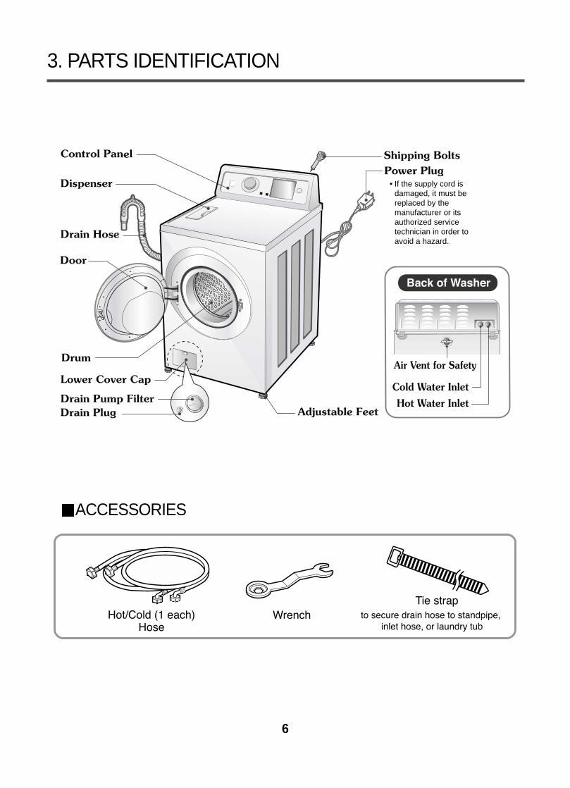
3. PARTS IDENTIFICATION
ACCESSORIES
• If the supply cord isdamaged, it must bereplaced by themanufacturer or itsauthorized servicetechnician in order toavoid a hazard.
7
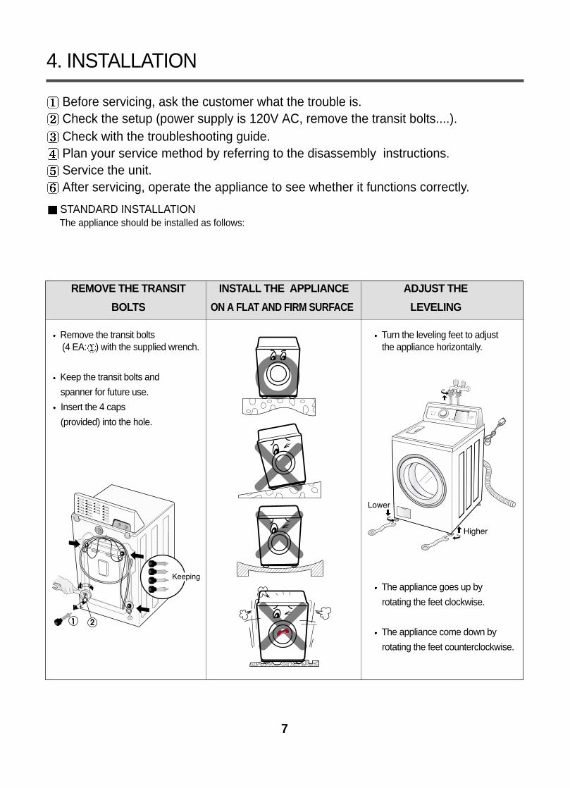
Before servicing, ask the customer what the trouble is.Check the setup (power supply is 120V AC, remove the transit bolts....).Check with the troubleshooting guide.Plan your service method by referring to the disassembly instructions.Service the unit.After servicing, operate the appliance to see whether it functions correctly.
STANDARD INSTALLATIONThe appliance should be installed as follows:
REMOVE THE TRANSIT INSTALL THE APPLIANCE ADJUST THE
BOLTS ON A FLAT AND FIRM SURFACE LEVELING
Remove the transit bolts Turn the leveling feet to adjust (4 EA: ) with the supplied wrench. the appliance horizontally.
Keep the transit bolts and
spanner for future use.
Insert the 4 caps
(provided) into the hole.
The appliance goes up by
rotating the feet clockwise.
The appliance come down by
rotating the feet counterclockwise.
4. INSTALLATION
8
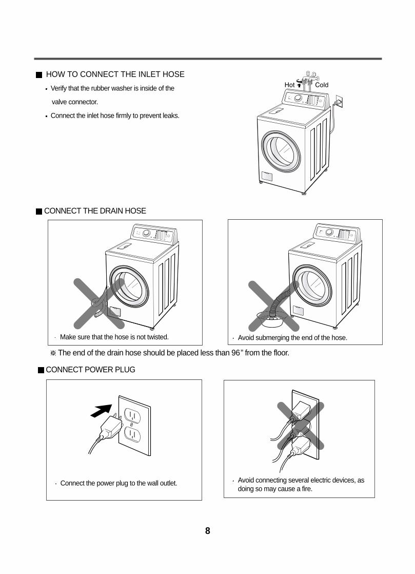
HOW TO CONNECT THE INLET HOSE
Verify that the rubber washer is inside of the
valve connector.
Connect the inlet hose firmly to prevent leaks.
CONNECT THE DRAIN HOSE
CONNECT POWER PLUG
The end of the drain hose should be placed less than 96” from the floor.
Connect the power plug to the wall outlet. Avoid connecting several electric devices, asdoing so may cause a fire.
Make sure that the hose is not twisted. Avoid submerging the end of the hose.
9
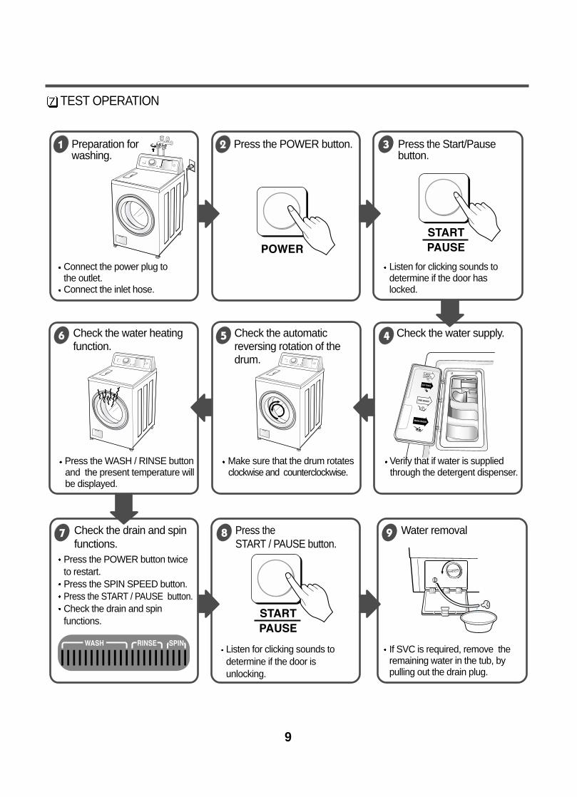
TEST OPERATION
Connect the power plug tothe outlet.Connect the inlet hose.
Press the POWER button twiceto restart.Press the SPIN SPEED button.Press the START / PAUSE button.Check the drain and spinfunctions.
Listen for clicking sounds todetermine if the door isunlocking.
Listen for clicking sounds todetermine if the door haslocked.
If SVC is required, remove theremaining water in the tub, bypulling out the drain plug.
Preparation for Press the POWER button. Press the Start/Pausewashing. button.
Press the WASH / RINSE button Make sure that the drum rotates Verify that if water is suppliedand the present temperature will clockwise and counterclockwise. through the detergent dispenser.be displayed.
Check the water heating Check the automatic Check the water supply.function. reversing rotation of the
drum.
Check the drain and spin Press the Water removal functions. START / PAUSE button.
10
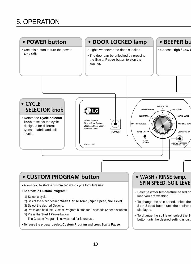
5. OPERATION
• Use this button to turn the power On / Off.
• Rotate the Cycle selectorknob to select the cycledesigned for differenttypes of fabric and soillevels.
• Allows you to store a customized wash cycle for future use.
• To create a Custom Program :
1) Select a cycle.2) Select the other desired Wash / Rinse Temp., Spin Speed, Soil Level.3) Select the desired Options.4) Press and hold the Custom Program button for 3 seconds (2 beep sounds).5) Press the Start / Pause button.
The Custom Program is now stored for future use.
• To reuse the program, select Custom Program and press Start / Pause.
• Lights whenever the door is locked.
• The door can be unlocked by pressingthe Start / Pause button to stop thewasher.
• Choose High / Low /
• Select a water temperature based onload you are washing.
• To change the spin speed, select the Spin Speed button until the desired sdisplayed.
• To change the soil level, select the Sobutton until the desired setting is disp
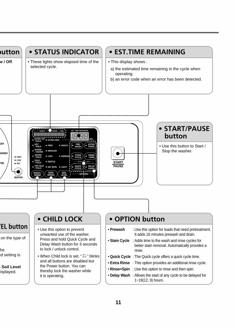
11
• Use this option to preventunwanted use of the washer.Press and hold Quick Cycle andDelay Wash button for 3 secondsto lock / unlock control.
• When Child lock is set, “ ” blinksand all buttons are disabled butthe Power button. You can thereby lock the washer while it is operating.
• Prewash : Use this option for loads that need pretreatment.It adds 16 minutes prewash and drain.
• Stain Cycle : Adds time to the wash and rinse cycles forbetter stain removal. Automatically provides arinse.
• Quick Cycle : The Quick cycle offers a quick cycle time.
• Extra Rinse : This option provides an additional rinse cycle.
• Rinse+Spin : Use this option to rinse and then spin.
• Delay Wash : Allows the start of any cycle to be delayed for1~19(12, 9) hours.
• Use this button to Start /Stop the washer.
w / Off.
on the type of
he ed setting is
e Soil Levelisplayed.
• These lights show elapsed time of theselected cycle.
• This display shows :
a) the estimated time remaining in the cycle whenoperating.
b) an error code when an error has been detected.
12
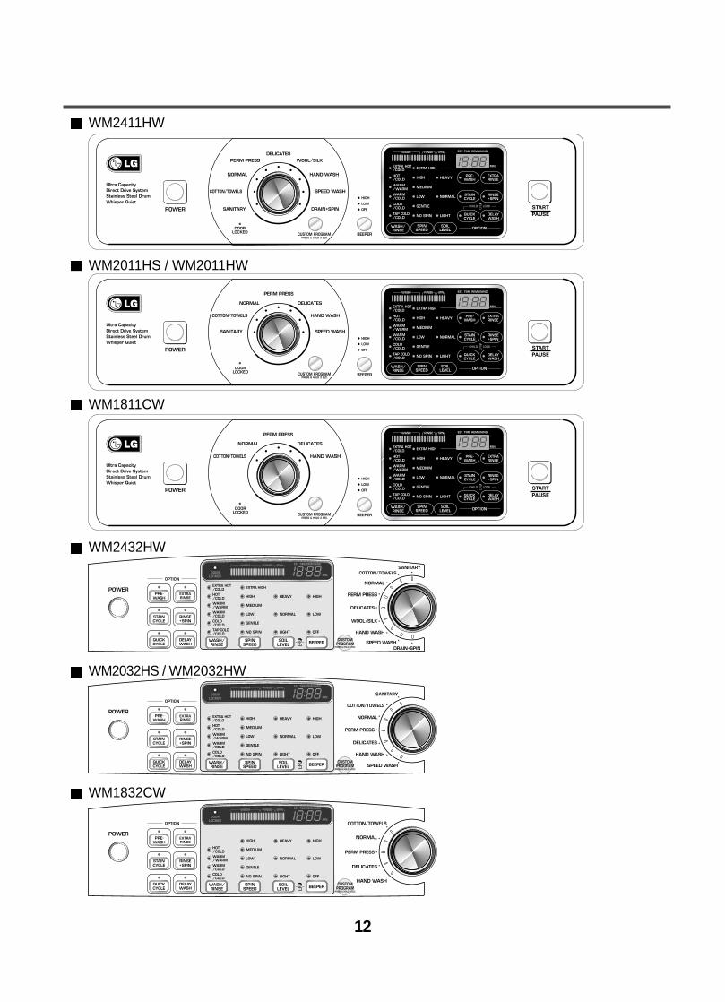
WM2411HW
WM2011HS / WM2011HW
WM1811CW
WM2432HW
WM2032HS / WM2032HW
WM1832CW

13
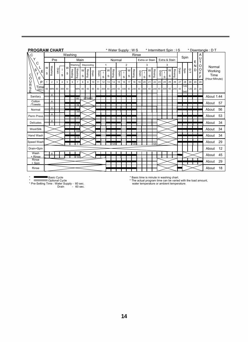
6. WIRING DIAGRAM / PROGRAM CHARTWM2411HW / WM2011HS / WM2011HW / WM2432HW / WM2032HS / WM2032HW
WM1811CW / WM1832CW
14
15
7. TROUBLESHOOTING
7-1. BEFORE PERFORMING SERVICEBe careful of electric shock when disconnecting parts for while troubleshooting.
The voltage of each terminal is 120V AC and DC when the unit is plugged in.
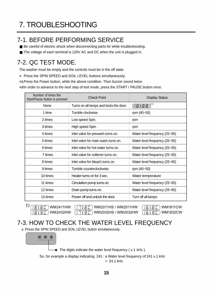
7-2. QC TEST MODE.The washer must be empty and the controls must be in the off state.
¤¤ÁPress the SPIN SPEED and SOIL LEVEL buttons simultaneously.
¤¤ŁŁPress the Power button, while the above condition. Then buzzer sound twice.
¤¤ØØIn order to advance to the next step of test mode, press the START / PAUSE button once.
7-3. HOW TO CHECK THE WATER LEVEL FREQUENCYPress the SPIN SPEED and SOIL LEVEL button simultaneously.
So, for example a display indicating 241 : a Water level frequency of 241 x.1 kHz= 24.1 kHz
The digits indicate the water level frequency ( x.1 kHz ).
Check Point Display Status
None Turns on all lamps and locks the door.
1 time Tumble clockwise. rpm (40~50)
2 times Low speed Spin. rpm
3 times High speed Spin. rpm
4 times Inlet valve for prewash turns on. Water level frequency (25~65)
5 times Inlet valve for main wash turns on. Water level frequency (25~65)
6 times Inlet valve for hot water turns on. Water level frequency (25~65)
7 times Inlet valve for softener turns on. Water level frequency (25~65)
8 times Inlet valve for bleach turns on. Water level frequency (25~65)
9 times Tumble counterclockwise. rpm (40~50)
10 times Heater turns on for 3 sec. Water temperature
11 times Circulation pump turns on. Water level frequency (25~65)
12 times Drain pump turns on. Water level frequency (25~65)
13 times Power off and unlock the door. Turn off all lamps.
Number of times theStart/Pause button is pressed
WM2411HW WM2011HS / WM2011HW WM1811CW
WM2432HW WM2032HS / WM2032HW WM1832CW
16
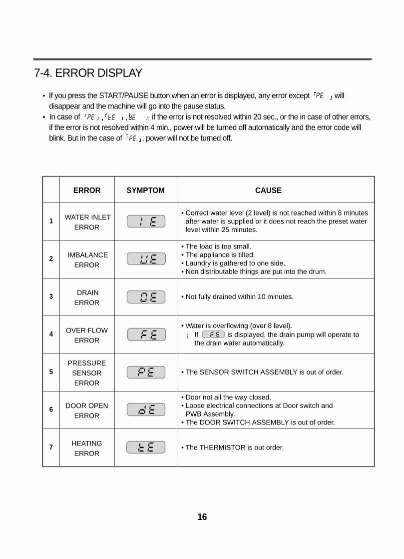
7-4. ERROR DISPLAY
If you press the START/PAUSE button when an error is displayed, any error except willdisappear and the machine will go into the pause status.In case of if the error is not resolved within 20 sec., or the in case of other errors,if the error is not resolved within 4 min., power will be turned off automatically and the error code willblink. But in the case of , power will not be turned off.
ERROR SYMPTOM CAUSE
WATER INLETERROR
• Correct water level (2 level) is not reached within 8 minutesafter water is supplied or it does not reach the preset waterlevel within 25 minutes.
• The load is too small.• The appliance is tilted.• Laundry is gathered to one side.• Non distributable things are put into the drum.
1
2 IMBALANCEERROR
• Not fully drained within 10 minutes.3 DRAINERROR
• Water is overflowing (over 8 level).¡ If is displayed, the drain pump will operate to
the drain water automatically.4 OVER FLOW
ERROR
• The SENSOR SWITCH ASSEMBLY is out of order.5PRESSURE
SENSOR ERROR
• Door not all the way closed.• Loose electrical connections at Door switch and
PWB Assembly.• The DOOR SWITCH ASSEMBLY is out of order.
6 DOOR OPENERROR
• The THERMISTOR is out order.7 HEATINGERROR
17
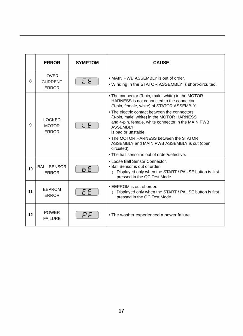
ERROR SYMPTOM CAUSE
OVERCURRENT
ERROR
• MAIN PWB ASSEMBLY is out of order.
• Winding in the STATOR ASSEMBLY is short-circuited.
• The connector (3-pin, male, white) in the MOTORHARNESS is not connected to the connector (3-pin, female, white) of STATOR ASSEMBLY.
• The electric contact between the connectors (3-pin, male, white) in the MOTOR HARNESS and 4-pin, female, white connector in the MAIN PWBASSEMBLY is bad or unstable.
• The MOTOR HARNESS between the STATORASSEMBLY and MAIN PWB ASSEMBLY is cut (opencircuited).
• The hall sensor is out of order/defective.
8
9LOCKEDMOTORERROR
• Loose Ball Sensor Connector.• Ball Sensor is out of order.¡ Displayed only when the START / PAUSE button is first
pressed in the QC Test Mode.
10 BALL SENSORERROR
• The washer experienced a power failure.12 POWERFAILURE
• EEPROM is out of order.¡ Displayed only when the START / PAUSE button is first
pressed in the QC Test Mode.11 EEPROM
ERROR
18
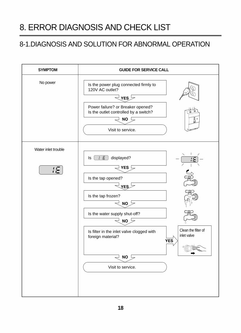
8-1.DIAGNOSIS AND SOLUTION FOR ABNORMAL OPERATION
8. ERROR DIAGNOSIS AND CHECK LIST
SYMPTOM GUIDE FOR SERVICE CALL
No power
Water inlet trouble
YES
YES
YES
NO
NO
YES
NO
NO
Is the power plug connected firmly to 120V AC outlet?
Power failure? or Breaker opened?Is the outlet controlled by a switch?
Visit to service.
Is displayed?
Is the tap opened?
Is the tap frozen?
Is the water supply shut-off?
Is filter in the inlet valve clogged withforeign material?
Visit to service.
Clean the filter ofinlet valve
19
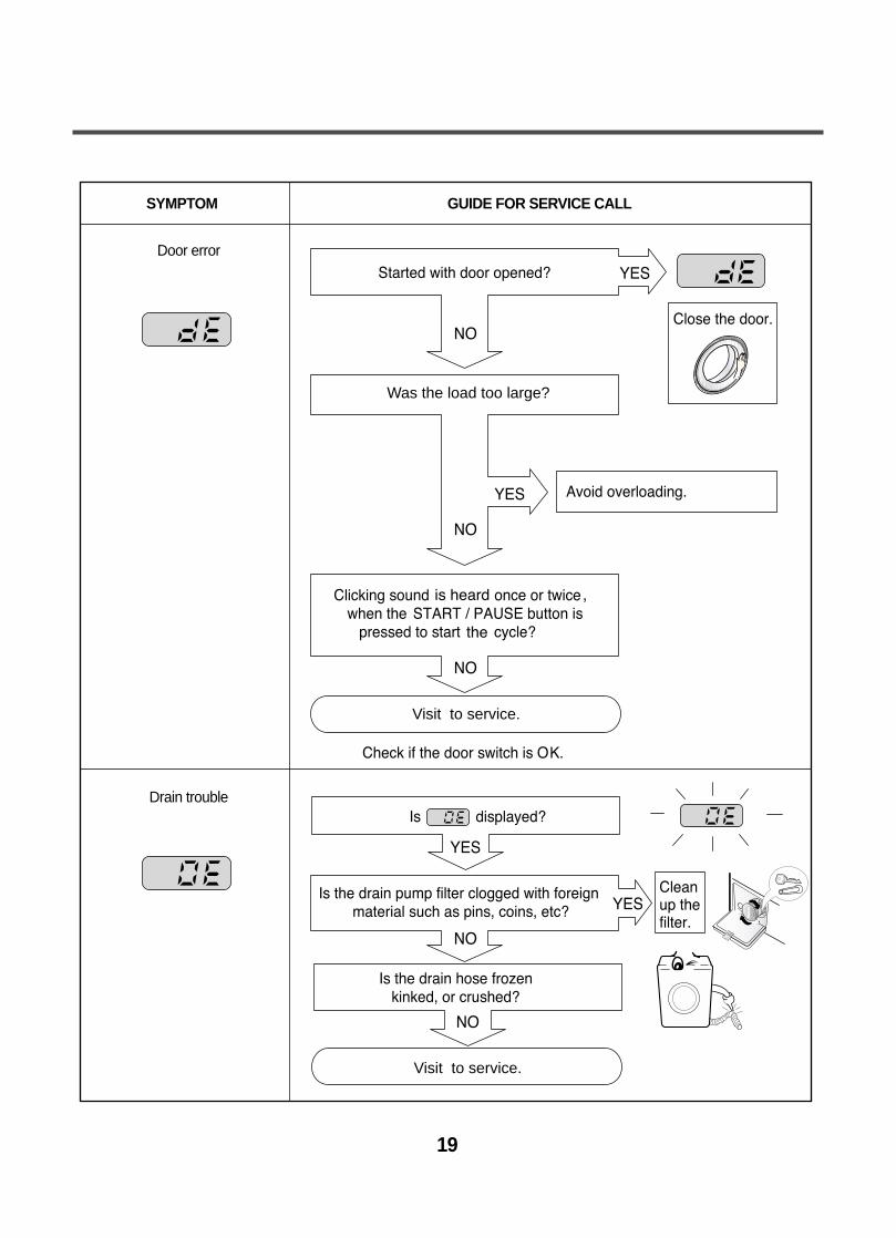
SYMPTOM GUIDE FOR SERVICE CALL
Door error
Drain trouble
Was the load too large?
Visit to service.
Visit to service.
20
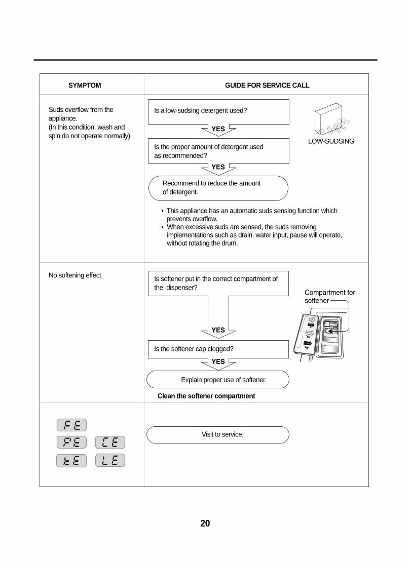
SYMPTOM GUIDE FOR SERVICE CALL
Suds overflow from theappliance.(In this condition, wash and spin do not operate normally)
No softening effect
YES
YES
YES
YES
Compartment forsoftener
Is a low-sudsing detergent used?
Is the proper amount of detergent used as recommended?
Recommend to reduce the amount of detergent.
Is softener put in the correct compartment ofthe dispenser?
Is the softener cap clogged?
Explain proper use of softener.
Clean the softener compartment
Visit to service.
LOW-SUDSING
This appliance has an automatic suds sensing function whichprevents overflow.When excessive suds are sensed, the suds removingimplementations such as drain, water input, pause will operate,without rotating the drum.
Connector
NO
YES
YES
YES
YES
NO
NO
NO
NO
YES
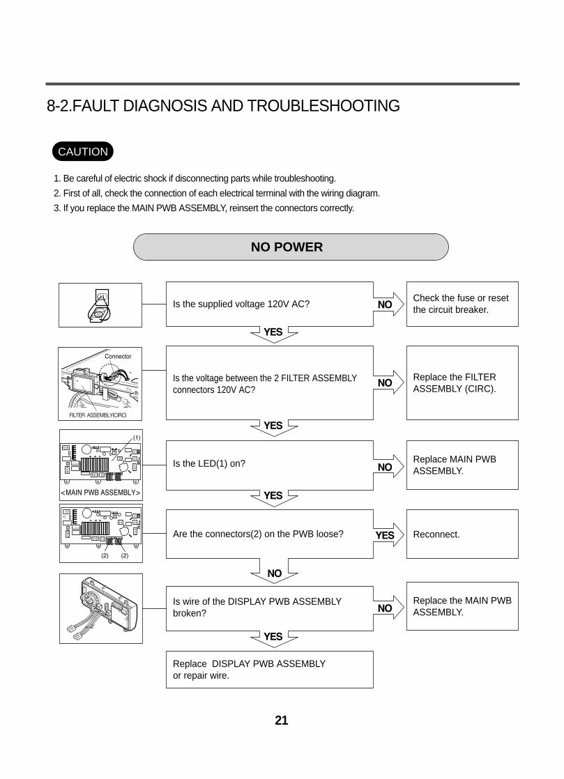
Is the supplied voltage 120V AC?
Is the voltage between the 2 FILTER ASSEMBLYconnectors 120V AC?
Is the LED(1) on?
Are the connectors(2) on the PWB loose?
Is wire of the DISPLAY PWB ASSEMBLY broken?
Replace DISPLAY PWB ASSEMBLY or repair wire.
Check the fuse or resetthe circuit breaker.
Replace the FILTERASSEMBLY (CIRC).
Replace MAIN PWBASSEMBLY.
Reconnect.
Replace the MAIN PWBASSEMBLY.
NO POWER
21
8-2.FAULT DIAGNOSIS AND TROUBLESHOOTING
1. Be careful of electric shock if disconnecting parts while troubleshooting.
2. First of all, check the connection of each electrical terminal with the wiring diagram.
3. If you replace the MAIN PWB ASSEMBLY, reinsert the connectors correctly.
CAUTION
NO
YES
NO
NO
YES
NO
YES
YES
NO
NO
YES
YES
YES
NO
NO
NO
YES
22
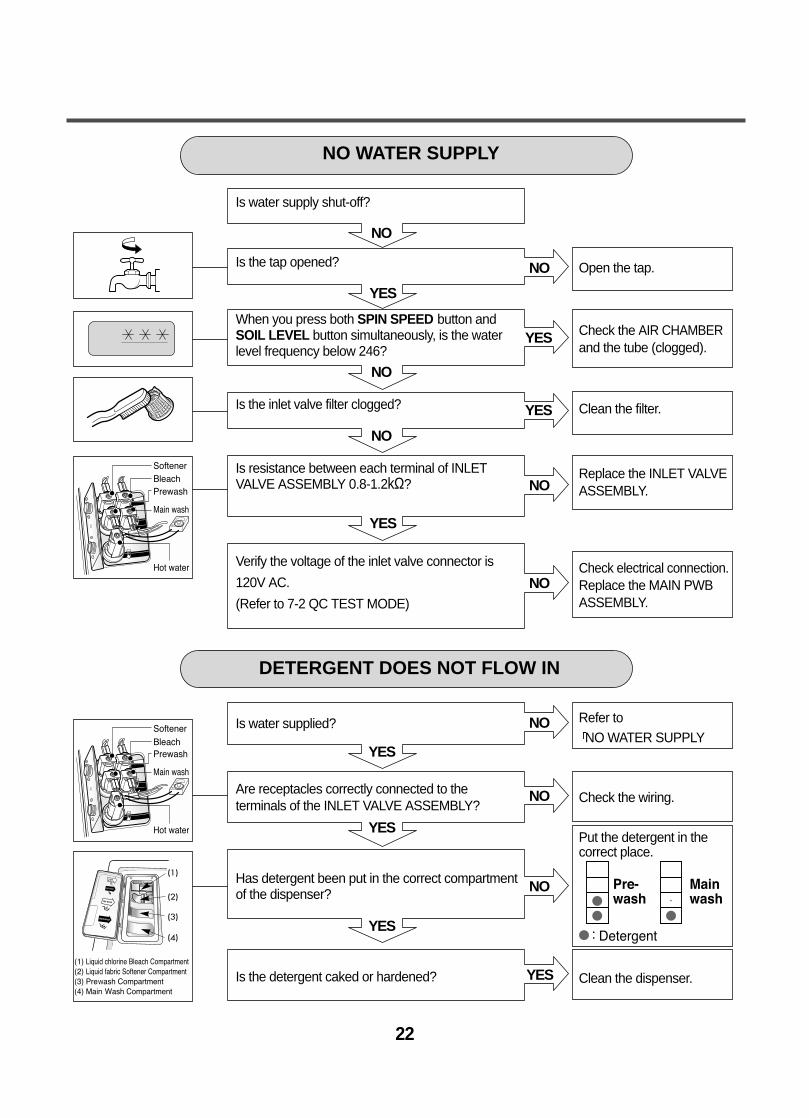
Is water supply shut-off?
Is the tap opened?
When you press both SPIN SPEED button andSOIL LEVEL button simultaneously, is the waterlevel frequency below 246?
Is the inlet valve filter clogged?
Is resistance between each terminal of INLETVALVE ASSEMBLY 0.8-1.2kΩ?
Verify the voltage of the inlet valve connector is
120V AC.
(Refer to 7-2 QC TEST MODE)
Is water supplied?
Are receptacles correctly connected to theterminals of the INLET VALVE ASSEMBLY?
Has detergent been put in the correct compartmentof the dispenser?
Is the detergent caked or hardened?
Open the tap.
Check the AIR CHAMBERand the tube (clogged).
Clean the filter.
Replace the INLET VALVEASSEMBLY.
Check electrical connection.Replace the MAIN PWBASSEMBLY.
Refer to NO WATER SUPPLY
Check the wiring.
Put the detergent in thecorrect place.
Clean the dispenser.
NO WATER SUPPLY
DETERGENT DOES NOT FLOW IN
23
ABNORMAL SOUND
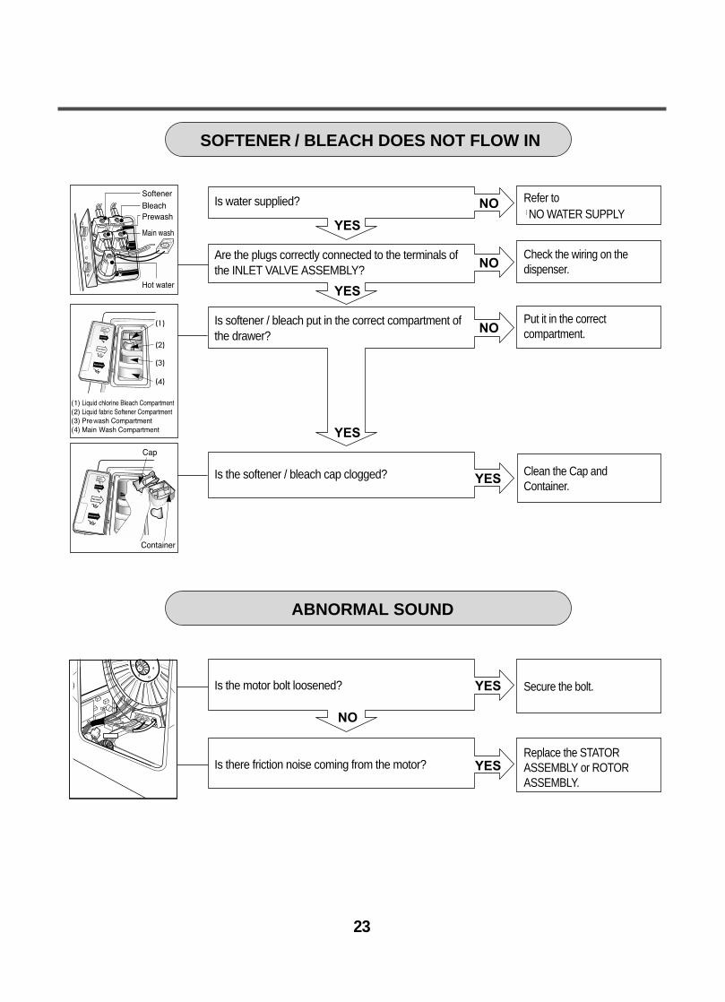
SOFTENER / BLEACH DOES NOT FLOW IN
Secure the bolt.
Replace the STATORASSEMBLY or ROTORASSEMBLY.
Refer toNO WATER SUPPLY
Check the wiring on the dispenser.
Put it in the correctcompartment.
Clean the Cap andContainer.
Is the motor bolt loosened?
Is there friction noise coming from the motor?
Is water supplied?
Are the plugs correctly connected to the terminals ofthe INLET VALVE ASSEMBLY?
Is softener / bleach put in the correct compartment ofthe drawer?
Is the softener / bleach cap clogged?

24
NO
YES
YES
YES
YES
NO
NO
NO
NO
YES
YES
NO
Replace theSENSOR SWITCHASSEMBLY.
Replace the MAIN PWBASSEMBLY.
Repair the DRAIN HOSE ASSEMBLY.
Remove foreign material.
Reconnect or repair theconnector
Replace the DRAINPUMP ASSEMBLY.
Replace the MAIN PWB ASSEMBLY.
When pressing SPIN SPEED and SOIL LEVEL at thesame time after draining, is the water level frequency255? When pressing SPIN SPEED and SOIL LEVEL buttonsat the same time while wash, is the water levelfrequency between 230 - 243 ?
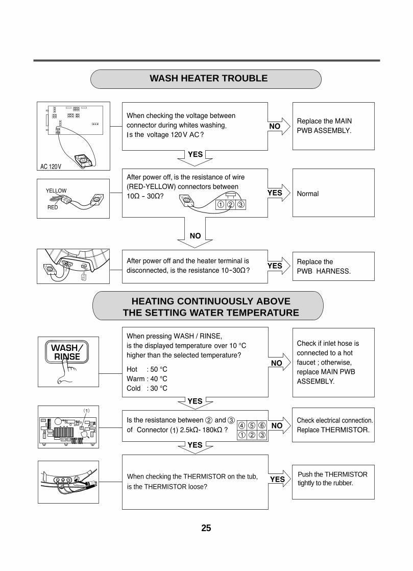
Check the voltage between two pins while pressingthe POWER button. Is the voltage 120V AC?
Is the drain hose twisted or frozen?
Is the impeller of the drain pump clogged?
Is the connector disconnected, disassembled?
Is the coil of the drain pump too high or low?(resistance of coil is 10-20Ω)
When checking voltage between connectors during
spin, is the voltage 120V AC as in the figure?
HEATING WITHOUT WATER
DRAIN MALFUNCTIONING
25
Push the THERMISTORtightly to the rubber.
When checking the THERMISTOR on the tub, is the THERMISTOR loose?
HEATING CONTINUOUSLY ABOVE THE SETTING WATER TEMPERATURE
WASH HEATER TROUBLE

YES
YES
YES
YESYES
NO
NO
NO
NO
NO
Hose
Connector
(White)
Connector
Connector
Hose
WILL NOT CIRCULATE WATER
Is the impeller of the drain pump clogged?
Are the Hose Connector and/or Hose clogged?
Is the connector disconnected, disassembled?
Is the coil of the right side of drain pump openor short circuited? (Coil R is 18-30Ω)
When checking voltage between the connectors during spin, is the voltage 120V AC,as the figure?
Remove foreign material.
Remove foreign material.
Reconnect or repair the connector.
Replace PUMP MOTORASSEMBLY.
Replace the MAIN PWBASSEMBLY.
26

27
SPIN TROUBLE
Check the SENSOR SWITCHASSEMBLY or HOSE (Pressure). If the problem is on the SENSORSWITCH ASSEMBLY or theHOSE, replace the SENSORSWITCH ASSEMBLY or theHOSE.
Normal
Correct the connection.
Replace the STATORASSEMBLY
Check during spin if the frequency of the waterlevel is 248 or more.
Press the START / PAUSE button 2 times in QCTest mode, is the drum spinning at low speed?
Is it disconnected, or disassembled?[Red:3pin (1), NA:4pin (2)]
Check the motor connector, Is the resistance ofthe terminal the same as the figure?MOTOR TERMINAL
Resistance of terminal: ¥L-¥M / ¥M-¥N / ¥N-¥L About 5Ω 15Ω
Replace the MAIN PWB ASSEMBLY
Does the spring of Latch Hook actuate?
Is there clicking sound once or twice when theSTART/PAUSE button is pressed to start the cycle?
Is DOOR SWITCH ASSEMBLY broken?
Replace Door Assembly.
Check the DOOR SWITCHASSEMBLY Connector andMAIN PWB ASSEMBLY(Red 4 pin and white 4 pinconnector (1)).
Replace the DOORSWITCH ASSEMBLY.
¥N ¥M ¥L
28
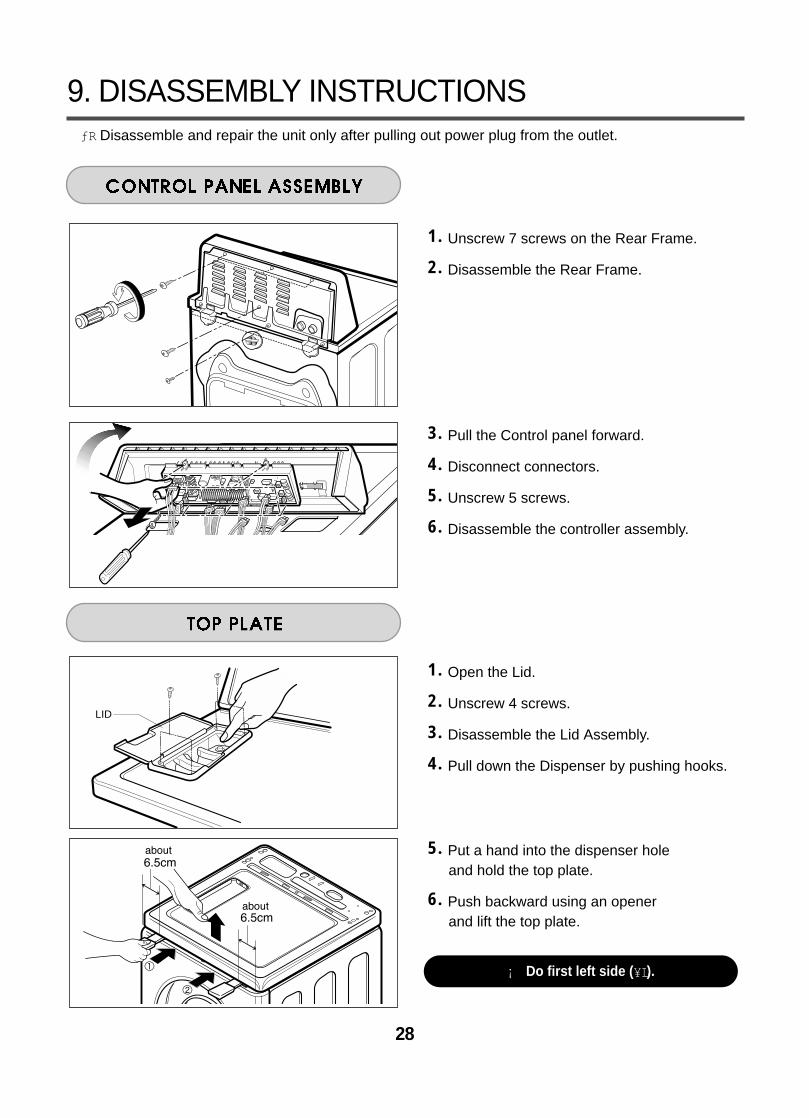
1. Unscrew 7 screws on the Rear Frame.
2. Disassemble the Rear Frame.
3. Pull the Control panel forward.
4. Disconnect connectors.
5. Unscrew 5 screws.
6. Disassemble the controller assembly.
1. Open the Lid.
2. Unscrew 4 screws.
3. Disassemble the Lid Assembly.
4. Pull down the Dispenser by pushing hooks.
5. Put a hand into the dispenser hole and hold the top plate.
6. Push backward using an opener and lift the top plate.
9. DISASSEMBLY INSTRUCTIONSƒR Disassemble and repair the unit only after pulling out power plug from the outlet.
LID
¡ Do first left side (¥L).
29
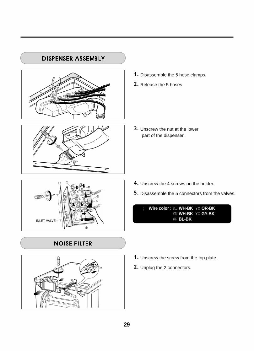
1. Disassemble the 5 hose clamps.
2. Release the 5 hoses.
3. Unscrew the nut at the lowerpart of the dispenser.
4. Unscrew the 4 screws on the holder.
5. Disassemble the 5 connectors from the valves.
1. Unscrew the screw from the top plate.
2. Unplug the 2 connectors.
¡ Wire color : ¥L WH-BK ¥M OR-BK¥N WH-BK ¥O GY-BK¥P BL-BK
30
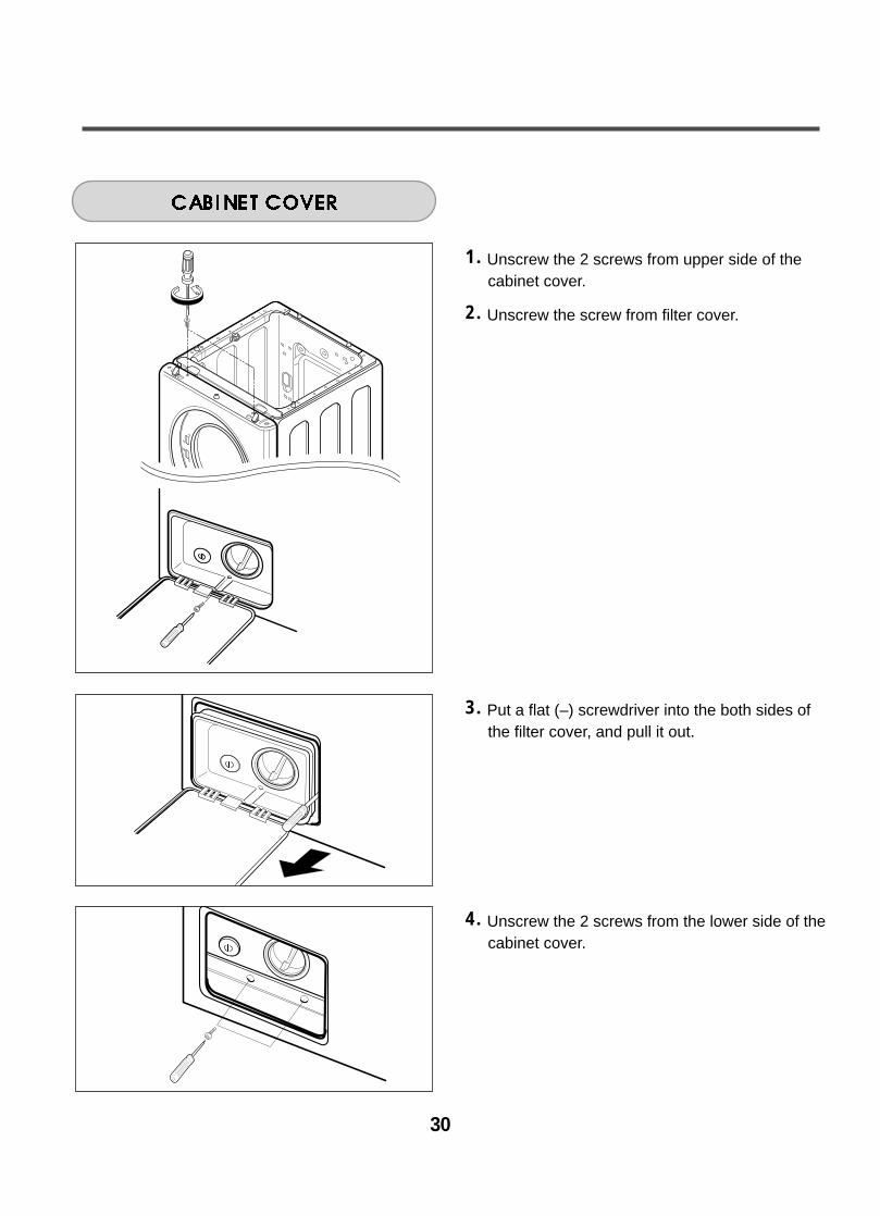
1. Unscrew the 2 screws from upper side of thecabinet cover.
2. Unscrew the screw from filter cover.
3. Put a flat (–) screwdriver into the both sides ofthe filter cover, and pull it out.
4. Unscrew the 2 screws from the lower side of thecabinet cover.

31
Clamp Assembly
5. Open the door.
6. Disassemble the clamp assembly using a flat (–) screwdriver.
7. Separate the clamp assembly from cabinetcover.
8. Tilt the cabinet cover.
9. Disconnect the door switch connector.
10. Lift and separate the cabinet cover.
11. Disassemble the clamp assembly using a flat (–) screwdriver.
12. Disasemble the Gasket.

32
1. Open the door.
2. Unscrew the 7 screws from the hinge cover.
3. Put a flat (–) screwdriver into the opening of thehinge, and pull out the hinge cover.
4. Unscrew the screws from the door.
5. Disassemble the door upward / downward.
1. Open the door.
2. Disassemble the clamp assembly.
3. Unscrew the 2 screws from cabinet cover.
¡ Be careful ! The door is heavy.

33
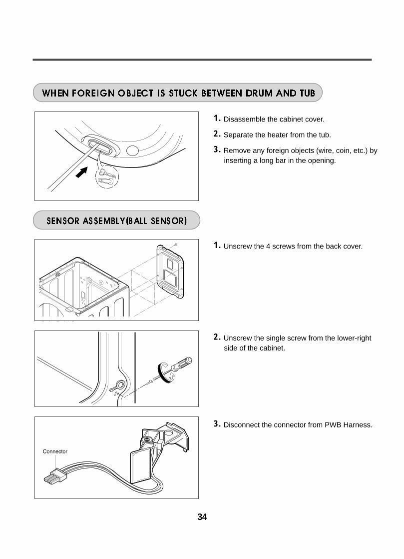
1. Disassemble the cabinet cover.
2. Separate the pump hose, the bellows and the circulation hose assembly from thepump assembly.
3. Disassemble the pump assembly in arrowdirection.
1. Disassemble the cabinet cover.
2. Separate 2 connectors from the heater.
3. Loose the nut and pull out the heater.
1. Disassemble the cabinet cover.
2. Unplug the white connector from the thermistor.
3. Pull it out by holding the bracket of thermistor.
¡ CAUTION• When assembling the heater, insert the heater
into heater clip on the bottom of the tub.• Tighten the fastening nut so the heater
is secure.
34
1. Disassemble the cabinet cover.
2. Separate the heater from the tub.
3. Remove any foreign objects (wire, coin, etc.) byinserting a long bar in the opening.
1. Unscrew the 4 screws from the back cover.
2. Unscrew the single screw from the lower-rightside of the cabinet.
3. Disconnect the connector from PWB Harness.
35
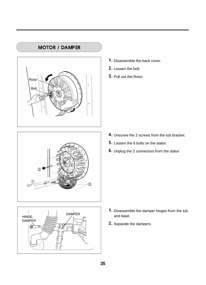
1. Disassemble the back cover.
2. Loosen the bolt.
3. Pull out the Rotor.
4. Unscrew the 2 screws from the tub bracket.
5. Loosen the 6 bolts on the stator.
6. Unplug the 2 connectors from the stator.
1. Disassemble the damper hinges from the tuband base.
2. Separate the dampers.

36
10-1. CABINET & CONTROL PANEL ASSEMBLY
10. EXPLODED VIEW
A160
A125
A105
F215
A495
A490
A303

37
K344 K345
K123
K115
K111
K340
F315
F463
K125
K343
K121
K101
K122
F141 K105
F463
F464
10-2. DRUM & TUB ASSEMBLY
38
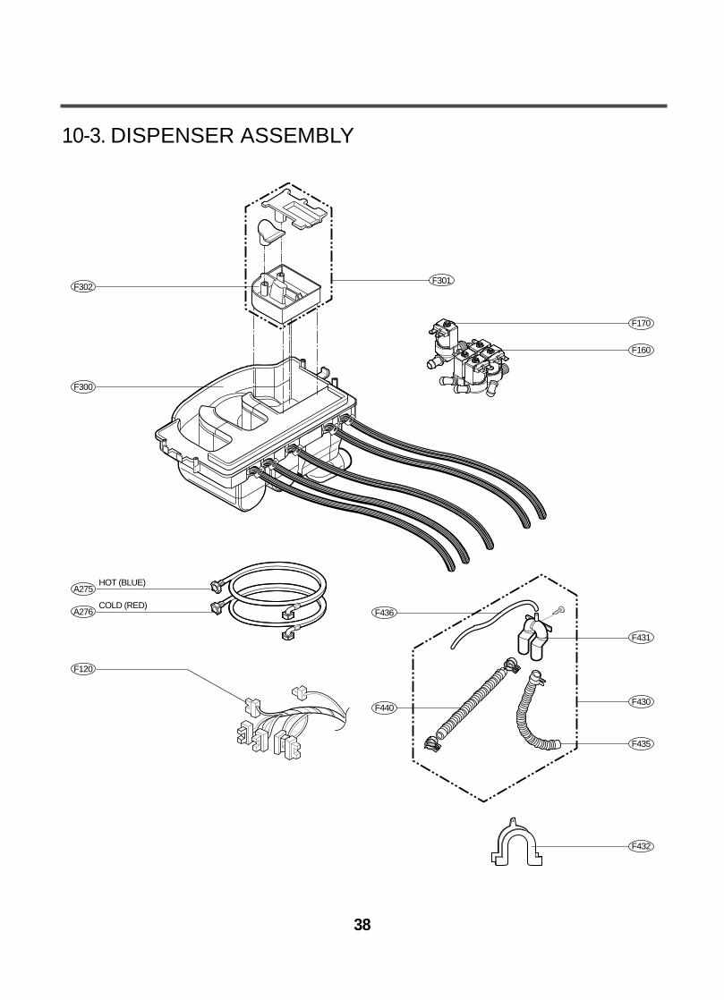
F300
F160
F170
F120
A275HOT (BLUE)
A276COLD (RED)
F430
F435
F431
F440
F436
F432
F302F301
10-3. DISPENSER ASSEMBLY

REPLACEMENT PARTS LIST
CAUTION : Before replacing any part of these components
Read carefully the safety precautions in this manual NOTE : S(Safety Parts), AL(Alternative parts)
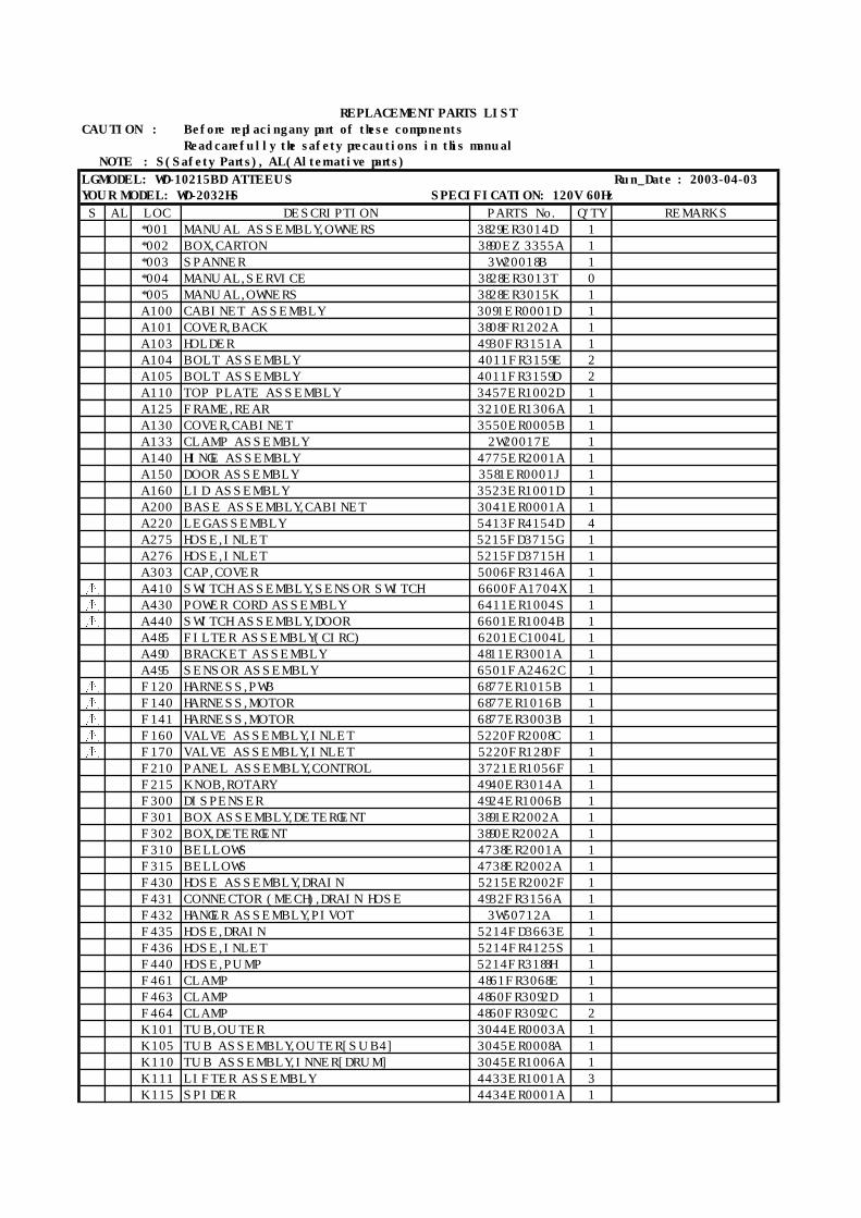
LG MODEL: WD-10210BD ABWEEUS Run_Date : 2003-04-03YOUR MODEL: WD-2032HW SPECIFICATION: 120V 60Hz
S AL LOC DESCRIPTION PARTS No. Q'TY REMARKS
*001 MANUAL ASSEMBLY,OWNERS 3829ER3014D 1
*002 BOX,CARTON 3890EZ3355A 1
*003 SPANNER 3W20018B 1
*004 MANUAL,SERVICE 3828ER3013T 0
*005 MANUAL,OWNERS 3828ER3015K 1
A100 CABINET ASSEMBLY 3091ER0001C 1
A101 COVER,BACK 3808FR1202A 1
A103 HOLDER 4930FR3151A 1
A104 BOLT ASSEMBLY 4011FR3159E 2
A105 BOLT ASSEMBLY 4011FR3159D 2
A110 TOP PLATE ASSEMBLY 3457ER1002A 1
A125 FRAME,REAR 3210ER1306A 1
A130 COVER,CABINET 3550ER0005A 1
A133 CLAMP ASSEMBLY 2W20017E 1
A140 HINGE ASSEMBLY 4775ER2001A 1
A150 DOOR ASSEMBLY 3581ER0001G 1
A160 LID ASSEMBLY 3523ER1001C 1
A200 BASE ASSEMBLY,CABINET 3041ER0001A 1
A220 LEG ASSEMBLY 5413FR4154D 4
A275 HOSE,INLET 5215FD3715G 1
A276 HOSE,INLET 5215FD3715H 1
A303 CAP,COVER 5006FR3146A 1
A410 SWITCH ASSEMBLY,SENSOR SWITCH 6600FA1704X 1
A430 POWER CORD ASSEMBLY 6411ER1004S 1
A440 SWITCH ASSEMBLY,DOOR 6601ER1004B 1
A485 FILTER ASSEMBLY(CIRC) 6201EC1004L 1
A490 BRACKET ASSEMBLY 4811ER3001A 1
A495 SENSOR ASSEMBLY 6501FA2462C 1
F120 HARNESS,PWB 6877ER1015B 1
F140 HARNESS,MOTOR 6877ER1016B 1
F141 HARNESS,MOTOR 6877ER3003B 1
F160 VALVE ASSEMBLY,INLET 5220FR2008C 1
F170 VALVE ASSEMBLY,INLET 5220FR1280F 1
F210 PANEL ASSEMBLY,CONTROL 3721ER1056G 1
F215 KNOB,ROTARY 4940ER3014A 1
F300 DISPENSER 4924ER1006B 1
F301 BOX ASSEMBLY,DETERGENT 3891ER2002A 1
F302 BOX,DETERGENT 3890ER2002A 1
F310 BELLOWS 4738ER2001A 1
F315 BELLOWS 4738ER2002A 1
F430 HOSE ASSEMBLY,DRAIN 5215ER2002F 1
F431 CONNECTOR (MECH),DRAIN HOSE 4932FR3156A 1
F432 HANGER ASSEMBLY,PIVOT 3W50712A 1
F435 HOSE,DRAIN 5214FD3663E 1
F436 HOSE,INLET 5214FR4125S 1
F440 HOSE,PUMP 5214FR3188H 1
F461 CLAMP 4861FR3068E 1
F463 CLAMP 4860FR3092D 1
F464 CLAMP 4860FR3092C 2
K101 TUB,OUTER 3044ER0003A 1
K105 TUB ASSEMBLY,OUTER[SUB4] 3045ER0008A 1
K110 TUB ASSEMBLY,INNER[DRUM] 3045ER1006A 1
K111 LIFTER ASSEMBLY 4433ER1001A 3
K115 SPIDER 4434ER0001A 1
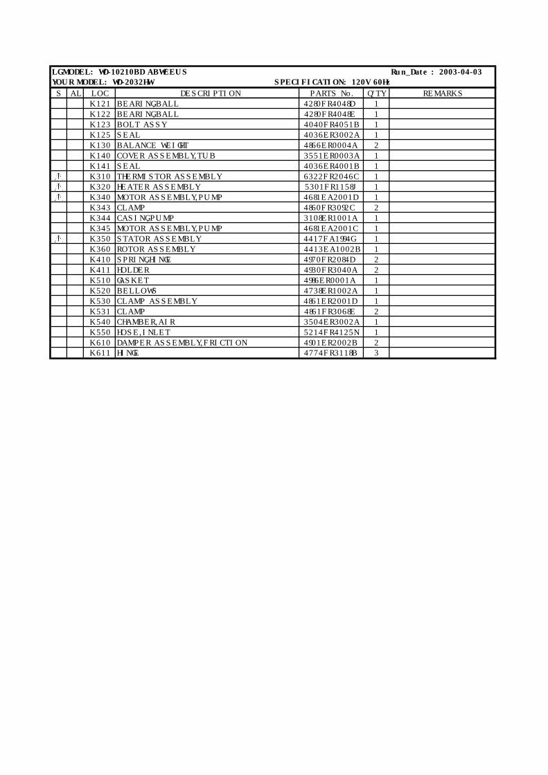
LG MODEL: WD-10210BD ABWEEUS Run_Date : 2003-04-03YOUR MODEL: WD-2032HW SPECIFICATION: 120V 60Hz
S AL LOC DESCRIPTION PARTS No. Q'TY REMARKS
K121 BEARING,BALL 4280FR4048D 1
K122 BEARING,BALL 4280FR4048E 1
K123 BOLT ASSY 4040FR4051B 1
K125 SEAL 4036ER3002A 1
K130 BALANCE WEIGHT 4866ER0004A 2
K140 COVER ASSEMBLY,TUB 3551ER0003A 1
K141 SEAL 4036ER4001B 1
K310 THERMISTOR ASSEMBLY 6322FR2046C 1
K320 HEATER ASSEMBLY 5301FR1158J 1
K340 MOTOR ASSEMBLY,PUMP 4681EA2001D 1
K343 CLAMP 4860FR3092C 2
K344 CASING,PUMP 3108ER1001A 1
K345 MOTOR ASSEMBLY,PUMP 4681EA2001C 1
K350 STATOR ASSEMBLY 4417FA1994G 1
K360 ROTOR ASSEMBLY 4413EA1002B 1
K410 SPRING,HINGE 4970FR2084D 2
K411 HOLDER 4930FR3040A 2
K510 GASKET 4986ER0001A 1
K520 BELLOWS 4738ER1002A 1
K530 CLAMP ASSEMBLY 4861ER2001D 1
K531 CLAMP 4861FR3068E 2
K540 CHAMBER,AIR 3504ER3002A 1
K550 HOSE,INLET 5214FR4125N 1
K610 DAMPER ASSEMBLY,FRICTION 4901ER2002B 2K611 HINGE 4774FR3118B 3
REPLACEMENT PARTS LIST
CAUTION : Before replacing any part of these components
Read carefully the safety precautions in this manual NOTE : S(Safety Parts), AL(Alternative parts)
LG MODEL: WD-10215BD ATTEEUS Run_Date : 2003-04-03YOUR MODEL: WD-2032HS SPECIFICATION: 120V 60Hz
S AL LOC DESCRIPTION PARTS No. Q'TY REMARKS
*001 MANUAL ASSEMBLY,OWNERS 3829ER3014D 1
*002 BOX,CARTON 3890EZ3355A 1
*003 SPANNER 3W20018B 1
*004 MANUAL,SERVICE 3828ER3013T 0
*005 MANUAL,OWNERS 3828ER3015K 1
A100 CABINET ASSEMBLY 3091ER0001D 1
A101 COVER,BACK 3808FR1202A 1
A103 HOLDER 4930FR3151A 1
A104 BOLT ASSEMBLY 4011FR3159E 2
A105 BOLT ASSEMBLY 4011FR3159D 2
A110 TOP PLATE ASSEMBLY 3457ER1002D 1
A125 FRAME,REAR 3210ER1306A 1
A130 COVER,CABINET 3550ER0005B 1
A133 CLAMP ASSEMBLY 2W20017E 1
A140 HINGE ASSEMBLY 4775ER2001A 1
A150 DOOR ASSEMBLY 3581ER0001J 1
A160 LID ASSEMBLY 3523ER1001D 1
A200 BASE ASSEMBLY,CABINET 3041ER0001A 1
A220 LEG ASSEMBLY 5413FR4154D 4
A275 HOSE,INLET 5215FD3715G 1
A276 HOSE,INLET 5215FD3715H 1
A303 CAP,COVER 5006FR3146A 1
A410 SWITCH ASSEMBLY,SENSOR SWITCH 6600FA1704X 1
A430 POWER CORD ASSEMBLY 6411ER1004S 1
A440 SWITCH ASSEMBLY,DOOR 6601ER1004B 1
A485 FILTER ASSEMBLY(CIRC) 6201EC1004L 1
A490 BRACKET ASSEMBLY 4811ER3001A 1
A495 SENSOR ASSEMBLY 6501FA2462C 1
F120 HARNESS,PWB 6877ER1015B 1
F140 HARNESS,MOTOR 6877ER1016B 1
F141 HARNESS,MOTOR 6877ER3003B 1
F160 VALVE ASSEMBLY,INLET 5220FR2008C 1
F170 VALVE ASSEMBLY,INLET 5220FR1280F 1
F210 PANEL ASSEMBLY,CONTROL 3721ER1056F 1
F215 KNOB,ROTARY 4940ER3014A 1
F300 DISPENSER 4924ER1006B 1
F301 BOX ASSEMBLY,DETERGENT 3891ER2002A 1
F302 BOX,DETERGENT 3890ER2002A 1
F310 BELLOWS 4738ER2001A 1
F315 BELLOWS 4738ER2002A 1
F430 HOSE ASSEMBLY,DRAIN 5215ER2002F 1
F431 CONNECTOR (MECH),DRAIN HOSE 4932FR3156A 1
F432 HANGER ASSEMBLY,PIVOT 3W50712A 1
F435 HOSE,DRAIN 5214FD3663E 1
F436 HOSE,INLET 5214FR4125S 1
F440 HOSE,PUMP 5214FR3188H 1
F461 CLAMP 4861FR3068E 1
F463 CLAMP 4860FR3092D 1
F464 CLAMP 4860FR3092C 2
K101 TUB,OUTER 3044ER0003A 1
K105 TUB ASSEMBLY,OUTER[SUB4] 3045ER0008A 1
K110 TUB ASSEMBLY,INNER[DRUM] 3045ER1006A 1
K111 LIFTER ASSEMBLY 4433ER1001A 3
K115 SPIDER 4434ER0001A 1

LG MODEL: WD-10215BD ATTEEUS Run_Date : 2003-04-03YOUR MODEL: WD-2032HS SPECIFICATION: 120V 60Hz
S AL LOC DESCRIPTION PARTS No. Q'TY REMARKS
K121 BEARING,BALL 4280FR4048D 1
K122 BEARING,BALL 4280FR4048E 1
K123 BOLT ASSY 4040FR4051B 1
K125 SEAL 4036ER3002A 1
K130 BALANCE WEIGHT 4866ER0004A 2
K140 COVER ASSEMBLY,TUB 3551ER0003A 1
K141 SEAL 4036ER4001B 1
K310 THERMISTOR ASSEMBLY 6322FR2046C 1
K320 HEATER ASSEMBLY 5301FR1158J 1
K340 MOTOR ASSEMBLY,PUMP 4681EA2001D 1
K343 CLAMP 4860FR3092C 2
K344 CASING,PUMP 3108ER1001A 1
K345 MOTOR ASSEMBLY,PUMP 4681EA2001C 1
K350 STATOR ASSEMBLY 4417FA1994G 1
K360 ROTOR ASSEMBLY 4413EA1002B 1
K410 SPRING,HINGE 4970FR2084D 2
K411 HOLDER 4930FR3040A 2
K510 GASKET 4986ER0001A 1
K520 BELLOWS 4738ER1002A 1
K530 CLAMP ASSEMBLY 4861ER2001D 1
K531 CLAMP 4861FR3068E 2
K540 CHAMBER,AIR 3504ER3002A 1
K550 HOSE,INLET 5214FR4125N 1
K610 DAMPER ASSEMBLY,FRICTION 4901ER2002B 2K611 HINGE 4774FR3118B 3
REPLACEMENT PARTS LIST
CAUTION : Before replacing any part of these components
Read carefully the safety precautions in this manual NOTE : S(Safety Parts), AL(Alternative parts)
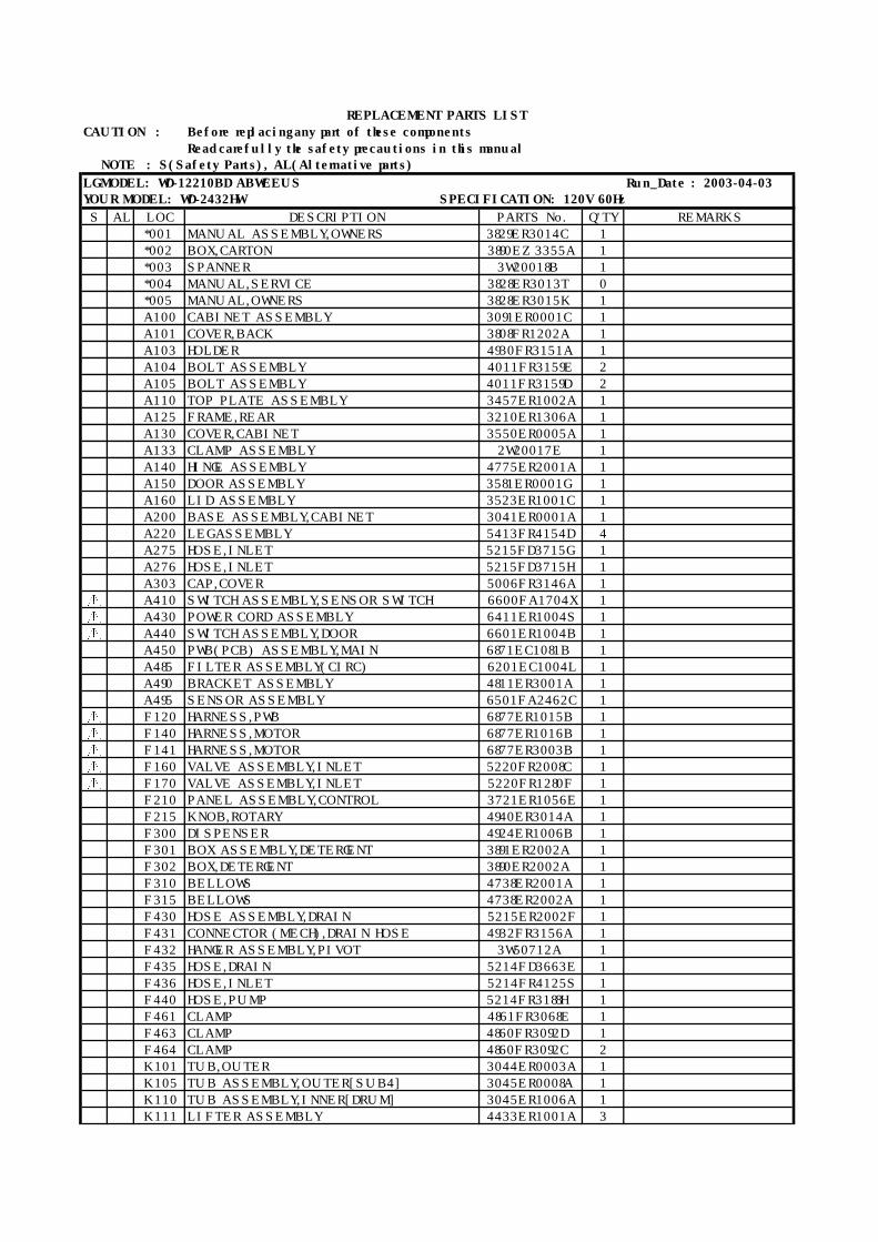
LG MODEL: WD-12210BD ABWEEUS Run_Date : 2003-04-03YOUR MODEL: WD-2432HW SPECIFICATION: 120V 60Hz
S AL LOC DESCRIPTION PARTS No. Q'TY REMARKS
*001 MANUAL ASSEMBLY,OWNERS 3829ER3014C 1
*002 BOX,CARTON 3890EZ3355A 1
*003 SPANNER 3W20018B 1
*004 MANUAL,SERVICE 3828ER3013T 0
*005 MANUAL,OWNERS 3828ER3015K 1
A100 CABINET ASSEMBLY 3091ER0001C 1
A101 COVER,BACK 3808FR1202A 1
A103 HOLDER 4930FR3151A 1
A104 BOLT ASSEMBLY 4011FR3159E 2
A105 BOLT ASSEMBLY 4011FR3159D 2
A110 TOP PLATE ASSEMBLY 3457ER1002A 1
A125 FRAME,REAR 3210ER1306A 1
A130 COVER,CABINET 3550ER0005A 1
A133 CLAMP ASSEMBLY 2W20017E 1
A140 HINGE ASSEMBLY 4775ER2001A 1
A150 DOOR ASSEMBLY 3581ER0001G 1
A160 LID ASSEMBLY 3523ER1001C 1
A200 BASE ASSEMBLY,CABINET 3041ER0001A 1
A220 LEG ASSEMBLY 5413FR4154D 4
A275 HOSE,INLET 5215FD3715G 1
A276 HOSE,INLET 5215FD3715H 1
A303 CAP,COVER 5006FR3146A 1
A410 SWITCH ASSEMBLY,SENSOR SWITCH 6600FA1704X 1
A430 POWER CORD ASSEMBLY 6411ER1004S 1
A440 SWITCH ASSEMBLY,DOOR 6601ER1004B 1
A450 PWB(PCB) ASSEMBLY,MAIN 6871EC1081B 1
A485 FILTER ASSEMBLY(CIRC) 6201EC1004L 1
A490 BRACKET ASSEMBLY 4811ER3001A 1
A495 SENSOR ASSEMBLY 6501FA2462C 1
F120 HARNESS,PWB 6877ER1015B 1
F140 HARNESS,MOTOR 6877ER1016B 1
F141 HARNESS,MOTOR 6877ER3003B 1
F160 VALVE ASSEMBLY,INLET 5220FR2008C 1
F170 VALVE ASSEMBLY,INLET 5220FR1280F 1
F210 PANEL ASSEMBLY,CONTROL 3721ER1056E 1
F215 KNOB,ROTARY 4940ER3014A 1
F300 DISPENSER 4924ER1006B 1
F301 BOX ASSEMBLY,DETERGENT 3891ER2002A 1
F302 BOX,DETERGENT 3890ER2002A 1
F310 BELLOWS 4738ER2001A 1
F315 BELLOWS 4738ER2002A 1
F430 HOSE ASSEMBLY,DRAIN 5215ER2002F 1
F431 CONNECTOR (MECH),DRAIN HOSE 4932FR3156A 1
F432 HANGER ASSEMBLY,PIVOT 3W50712A 1
F435 HOSE,DRAIN 5214FD3663E 1
F436 HOSE,INLET 5214FR4125S 1
F440 HOSE,PUMP 5214FR3188H 1
F461 CLAMP 4861FR3068E 1
F463 CLAMP 4860FR3092D 1
F464 CLAMP 4860FR3092C 2
K101 TUB,OUTER 3044ER0003A 1
K105 TUB ASSEMBLY,OUTER[SUB4] 3045ER0008A 1
K110 TUB ASSEMBLY,INNER[DRUM] 3045ER1006A 1
K111 LIFTER ASSEMBLY 4433ER1001A 3
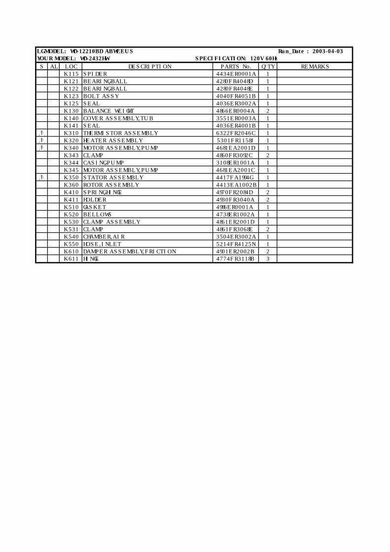
LG MODEL: WD-12210BD ABWEEUS Run_Date : 2003-04-03YOUR MODEL: WD-2432HW SPECIFICATION: 120V 60Hz
S AL LOC DESCRIPTION PARTS No. Q'TY REMARKS
K115 SPIDER 4434ER0001A 1
K121 BEARING,BALL 4280FR4048D 1
K122 BEARING,BALL 4280FR4048E 1
K123 BOLT ASSY 4040FR4051B 1
K125 SEAL 4036ER3002A 1
K130 BALANCE WEIGHT 4866ER0004A 2
K140 COVER ASSEMBLY,TUB 3551ER0003A 1
K141 SEAL 4036ER4001B 1
K310 THERMISTOR ASSEMBLY 6322FR2046C 1
K320 HEATER ASSEMBLY 5301FR1158J 1
K340 MOTOR ASSEMBLY,PUMP 4681EA2001D 1
K343 CLAMP 4860FR3092C 2
K344 CASING,PUMP 3108ER1001A 1
K345 MOTOR ASSEMBLY,PUMP 4681EA2001C 1
K350 STATOR ASSEMBLY 4417FA1994G 1
K360 ROTOR ASSEMBLY 4413EA1002B 1
K410 SPRING,HINGE 4970FR2084D 2
K411 HOLDER 4930FR3040A 2
K510 GASKET 4986ER0001A 1
K520 BELLOWS 4738ER1002A 1
K530 CLAMP ASSEMBLY 4861ER2001D 1
K531 CLAMP 4861FR3068E 2
K540 CHAMBER,AIR 3504ER3002A 1
K550 HOSE,INLET 5214FR4125N 1
K610 DAMPER ASSEMBLY,FRICTION 4901ER2002B 2K611 HINGE 4774FR3118B 3

REPLACEMENT PARTS LIST
CAUTION : Before replacing any part of these components
Read carefully the safety precautions in this manual NOTE : S(Safety Parts), AL(Alternative parts)
LG MODEL: WD-90210BD ABWEEUS Run_Date : 2003-04-03YOUR MODEL: WD-1832CW SPECIFICATION: 120V 60Hz
S AL LOC DESCRIPTION PARTS No. Q'TY REMARKS
*001 MANUAL ASSEMBLY,OWNERS 3829ER3014E 1
*002 BOX,CARTON 3890EZ3355A 1
*003 SPANNER 3W20018B 1
*004 MANUAL,SERVICE 3828ER3013T 0
*005 MANUAL,OWNERS 3828ER3015K 1
A100 CABINET ASSEMBLY 3091ER0001C 1
A101 COVER,BACK 3808FR1202A 1
A103 HOLDER 4930FR3151A 1
A104 BOLT ASSEMBLY 4011FR3159E 2
A105 BOLT ASSEMBLY 4011FR3159D 2
A110 TOP PLATE ASSEMBLY 3457ER1002C 1
A125 FRAME,REAR 3210ER1306A 1
A130 COVER,CABINET 3550ER0005A 1
A133 CLAMP ASSEMBLY 2W20017E 1
A140 HINGE ASSEMBLY 4775ER2001A 1
A150 DOOR ASSEMBLY 3581ER0001F 1
A160 LID ASSEMBLY 3523ER1001C 1
A200 BASE ASSEMBLY,CABINET 3041ER0001B 1
A220 LEG ASSEMBLY 5413FR4154D 4
A275 HOSE,INLET 5215FD3715G 1
A276 HOSE,INLET 5215FD3715H 1
A303 CAP,COVER 5006FR3146A 1
A410 SWITCH ASSEMBLY,SENSOR SWITCH 6600FA1704X 1
A430 POWER CORD ASSEMBLY 6411ER1004S 1
A440 SWITCH ASSEMBLY,DOOR 6601ER1004B 1
A485 FILTER ASSEMBLY(CIRC) 6201EC1004L 1
A490 BRACKET ASSEMBLY 4811ER3001A 1
A495 SENSOR ASSEMBLY 6501FA2462C 1
F120 HARNESS,PWB 6877ER1015C 1
F140 HARNESS,MOTOR 6877ER1016B 1
F141 HARNESS,MOTOR 6877ER3003C 1
F160 VALVE ASSEMBLY,INLET 5220FR2008C 1
F170 VALVE ASSEMBLY,INLET 5220FR1280F 1
F210 PANEL ASSEMBLY,CONTROL 3721ER1056H 1
F215 KNOB,ROTARY 4940ER3014A 1
F300 DISPENSER 4924ER1006B 1
F301 BOX ASSEMBLY,DETERGENT 3891ER2002A 1
F302 BOX,DETERGENT 3890ER2002A 1
F310 BELLOWS 4738ER2001A 1
F315 BELLOWS 4738ER2002A 1
F430 HOSE ASSEMBLY,DRAIN 5215ER2002F 1
F431 CONNECTOR (MECH),DRAIN HOSE 4932FR3156A 1
F432 HANGER ASSEMBLY,PIVOT 3W50712A 1
F435 HOSE,DRAIN 5214FD3663E 1
F436 HOSE,INLET 5214FR4125S 1
F440 HOSE,PUMP 5214FR3188H 1
F461 CLAMP 4861FR3068E 1
F463 CLAMP 4860FR3092D 1
F464 CLAMP 4860FR3092C 2
K101 TUB,OUTER 3044ER0003A 1
K105 TUB ASSEMBLY,OUTER[SUB4] 3045ER0008C 1
K110 TUB ASSEMBLY,INNER[DRUM] 3045ER1006B 1
K111 LIFTER ASSEMBLY 4433ER1001B 3
K115 SPIDER 4434ER0001A 1
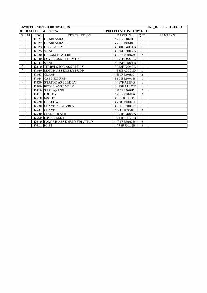
LG MODEL: WD-90210BD ABWEEUS Run_Date : 2003-04-03YOUR MODEL: WD-1832CW SPECIFICATION: 120V 60Hz
S AL LOC DESCRIPTION PARTS No. Q'TY REMARKS
K121 BEARING,BALL 4280FR4048D 1
K122 BEARING,BALL 4280FR4048E 1
K123 BOLT ASSY 4040FR4051B 1
K125 SEAL 4036ER3002A 1
K130 BALANCE WEIGHT 4866ER0004A 2
K140 COVER ASSEMBLY,TUB 3551ER0003C 1
K141 SEAL 4036ER4001B 1
K310 THERMISTOR ASSEMBLY 6322FR2046C 1
K340 MOTOR ASSEMBLY,PUMP 4681EA2001D 1
K343 CLAMP 4860FR3092C 2
K344 CASING,PUMP 3108ER1001B 1
K350 STATOR ASSEMBLY 4417FA1994G 1
K360 ROTOR ASSEMBLY 4413EA1002B 1
K410 SPRING,HINGE 4970FR2084D 2
K411 HOLDER 4930FR3040A 2
K510 GASKET 4986ER0001B 1
K520 BELLOWS 4738ER1002A 1
K530 CLAMP ASSEMBLY 4861ER2001D 1
K531 CLAMP 4861FR3068E 2
K540 CHAMBER,AIR 3504ER3002A 1
K550 HOSE,INLET 5214FR4125N 1
K610 DAMPER ASSEMBLY,FRICTION 4901ER2002B 2K611 HINGE 4774FR3118B 3


101
DEC. 2002 PRINTED IN KOREA P/No.:3828ER3013T