warning! this material may be redistributed freely but … can be reached at [email protected] ....
TRANSCRIPT

Warning!The material expressed in this document is the personal view of the author. This
information is to be used for informational and entertainment purposes only! The author of this document assumes no responsibility or liability for damage to firearms, bodily harm or
death to the reader or bystanders of the reader should the reader decide to attempt to duplicate procedures documented here. If the reader of this document is unsure of his or
her own capability to safely perform personal maintenance on any firearm the reader should seek the help and council of a credible gunsmith.
This material may be redistributed freely but may not be copyrighted or redistributed for a fee or charge of any kind unless authorized by “TonyBen”, the author of this document,
who can be reached at [email protected] .
This document is intended to illustrate the tools and techniques necessary to field strip and disassemble M14 rifle clones. Disassembly will cover everything except the trigger group disassembly, and small parts disassembly like the spindle valve in the gas cylinder and the cartridge clip guide on the receiver as well as the operating rod guide and the bolt stop. These items rarely, if ever, need to be removed once they are installed by the factory or by a gunsmith.
Below are some common tools necessary to properly disassemble, clean and maintain your M14-type rifle. Not all tools shown are necessary for disassembly.
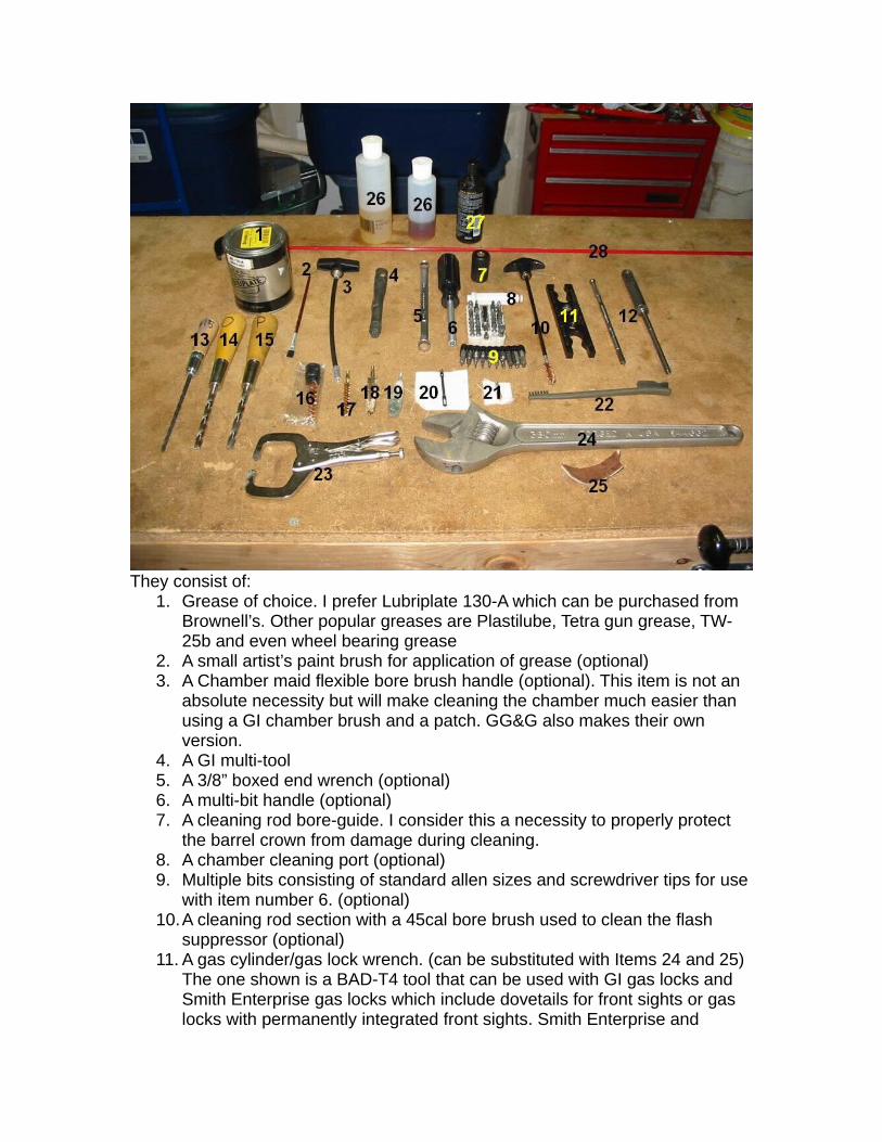
They consist of:1. Grease of choice. I prefer Lubriplate 130-A which can be purchased from
Brownell’s. Other popular greases are Plastilube, Tetra gun grease, TW-25b and even wheel bearing grease
2. A small artist’s paint brush for application of grease (optional)3. A Chamber maid flexible bore brush handle (optional). This item is not an
absolute necessity but will make cleaning the chamber much easier than using a GI chamber brush and a patch. GG&G also makes their own version.
4. A GI multi-tool5. A 3/8” boxed end wrench (optional)6. A multi-bit handle (optional)7. A cleaning rod bore-guide. I consider this a necessity to properly protect
the barrel crown from damage during cleaning. 8. A chamber cleaning port (optional)9. Multiple bits consisting of standard allen sizes and screwdriver tips for use
with item number 6. (optional)10.A cleaning rod section with a 45cal bore brush used to clean the flash
suppressor (optional)11. A gas cylinder/gas lock wrench. (can be substituted with Items 24 and 25)
The one shown is a BAD-T4 tool that can be used with GI gas locks and Smith Enterprise gas locks which include dovetails for front sights or gas locks with permanently integrated front sights. Smith Enterprise and

Sadlak also sell versions and there are also GI gas lock wrenches available.
12.A BAD-T1 tool (optional). This tool can be used to disassemble the M14 rifle and includes integrated gauges to measure muzzle wear, throat erosion and flash suppressor alignment. It also includes a storage pot for grease and can also be used with multi-bits (allen and screwdriver bits). It also has an adapter to measure throat erosion on M1 Garands. The tool is very expensive but is well worth the money if you are in the habit of measuring and monitoring throat erosion and muzzle wear as well as frequent self-gunsmithing.
13.A #15 long drill bit with handle. This is needed to clean inside the gas piston tail.
14.A letter “O” drill bit. This will be used to clean the inside of the gas plug.15.A letter “P” drill bit. This will be used to clean the large opening in the gas
piston.16.A GI chamber brush. (Optional with suitable substitute)17.A .30 caliber bore brush with brass shank.18.A 45 caliber bore brush used to clean the chamber in place of a GI
chamber brush (optional).19.A 45 caliber bore mop (optional). This will make thorough removal of
solvents much easier and quicker.20. If using an eyelet attachment to clean the bore, use an eyelet with a 30
caliber cotton cleaning patch.21. If using a cleaning jag, use a jag with a 22 caliber cotton cleaning patch or
a 30 caliber cotton cleaning patch cut in half. 22.A nylon cleaning brush.23.A set of castle nut pliers. The ones shown are home made but others can
be purchased on gunbroker or Brownell’s.24.A large crescent wrench as a substitute for a gas lock wrench (item
number 11).25.A strip of leather for use with item 24.26.Solvent of choice.27.Oil of choice.28.A one piece cleaning rod. It doesn’t have to be an expensive cleaning rod.
The expensive ones are nice but I used a $12 coated cleaning rod and it worked fine. When using a jag to clean the barrel instead of an eyelet, it will take more effort to push it through the barrel and you may bend it. The expensive ones won’t bend but as long as you are careful, a cheap one will do fine.
Disassembly

First, remove the magazine from the rifle
Pull the operating rod back and verify that the rifle is unloaded and there is no round in the chamber. Ease the operating rod forward when clear.

Invert the rifle and protect your rear sight group. You can install a rear sight protector or lay the rifle on a piece of wood to keep the weight of the rifle from damaging the rear sight. Using a BAD-T1 tool section or a suitable
substitute, insert the tool into the hole at the rear of the trigger guard and pull up to open the trigger guard.
Use of GI multi-tool shown

Unlock the trigger group
Once opened, pull the trigger group straight out.
Important note: if your rifle is equipped with a rear lugged receiver or double lugged receiver and torque screw(s), remove the torque screw(s) now. The rear screw is accessible after you remove the trigger group! The forward torque screw can be accessed at any time.

If the trigger guard will not fully open and you can’t remove the trigger group from the rifle, there is a possibility that the roll pin that holds the
magazine latch in has backed out creating a mechanical block that will not allow the trigger guard to open. If this happens, insert a screwdriver and
push the roll pin back in place.
Once the trigger guard is removed, turn the rifle right side up and grab the receiver by the rear sight knobs. With your free hand, slap down on the grip
area of the stock to separate the barreled action from the stock.

For glass bedded stocks with a tight fit, you may not be able to get the action out this way. For stubborn stocks I recommend finding a hard work surface and laying a folded towel down on it for protection. Invert the rifle and with one hand grab the barrel/gas cylinder. With the other hand, support the receiver and bump the buttstock down on the padded work surface.
This should separate the stock and action as shown in the two images above and below. Be sure not to drop the stock on the floor when this happens as it may fly off when it separates under force so be prepared to catch it. This may also be a good method to remove the stock from an action that has a scope mounted which you might not want to remove for disassembly and at the same time don’t want to use the scope as a handle during disassembly.

The rifle is now broken down into three groups; the barreled action, the stock and the trigger group.
(Optional) Bolt disassembly using a spent 30-06 or .270 shell casing:This is probably, by far, the easiest way to remove the extractor from the bolt that I have seen done short of buying a bolt disassembly tool. This method will remove very stubborn extractors that can’t be removed using a GI multi-tool. Some commercial extractors have a dimple for the extractor plunger that is too deep and makes removal of the extractor more difficult.
This procedure should be performed either before you remove the action from the stock or before you remove the operating rod and operating rod spring from the action.

Tools necessary are for bolt disassembly using an empty 30-06 casing are: A small gunsmith’s hammer, a 5/32” punch and an empty 30-06 or .270
Case.
Insert the empty case into the chamber.

Ease the bolt forward and bump the operating rod handle until the extractor clamps over the rim of the empty case. This will compress the ejector and allow for the extractor to be punched out from the bottom. This also allows the operating rod spring to do all the work compressing the ejector spring
while you focus on removing the extractor.
Place the 5/32” punch directly over the leg of the extractor.

Give the punch a good firm tap and the extractor should fall out of the top of the bolt.
To remove the punch, press the operating rod handle forward to compress the ejector a little more and relieve pressure on the punch. Remove the
punch and ease the operating rod back. The bolt will literally fall apart from this point on and the empty case and bolt guts can be removed.
Removal of the operating rod, spring guide, spring and bolt:

Invert the barreled action and pull the operating rod spring back, relieving pressure on the operating rod spring guide. Disengage the connector lock
from the spring guide.
You may now remove the spring guide and spring.
Location of the dismount notch just below the rear sight windage knob.

Pull back the operating rod so that the tab that rides inside the track is lined up with the dismount notch.
Lift up and rotate out on the operating rod handle to dismount the operating rod tab from the tab track in the receiver.

Dismounted
(Optional) If this is your first time removing an operating rod from a new rifle, it may be too difficult to remove the operating rod from the receiver with your hands. In this case you can wrap a piece of leather around the operating rod
handle and grip it with some channel-locks to gain the extra leverage necessary to remove the operating rod the first few times. Gently but firmly rotate the operating rod handle out and up. After the operating rod has been
removed a few times it will almost fall out on its own.

Now pull the bolt forward, up and out of the receiver. Observe the firing pin tail and wiggle or rotate the bolt until the tail clears the groove in the
receiver safety bridge.
Using a 1/16” Allen wrench or Allen bit, remove the flash suppressor castle nut set screw
Install the gas lock wrench and the castle nut pliers and loosen the castle nut. You can also substitute the gas lock wrench with a padded crescent
wrench (shown 2 images below).

Remove the flash suppressor and castle nut.
Using either a BAD-T1 tool, GI multi tool or a 3/8” boxed end wrench, loosen and remove the gas plug. It is a good idea to make a witness mark
with white-out or white paint before removal to identify proper torque if you don’t have a torque wrench to reinstall the gas plug.

Gas plug removed
Loosen the gas lock

Unscrew and remove the gas lock
Slide the gas cylinder and front band forward and remove
Slide out the gas piston
Slide the handguard forward and remove.

Before disassembling the rear sight group, bottom out the rear sight and center the windage settings. Note the elevation settings to ensure the elevation knob is installed in the same orientation as it was removed. If it is not reinstalled exactly as it was removed, the elevation settings will not match and the elevation knob will need to be adjusted upon reassembly. It is also a good idea to count the clicks from bottom that it takes to reach your 200 yard zero. This knowledge will enable you to adjust the elevation knob to the correct setting instead of having to re zero the sights at the range.
Using a BAD-T1 tool, a multi-tool or a standard screwdriver, loosen the split nut in the windage knob.
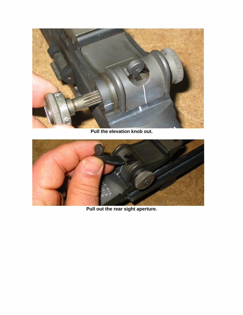
Pull the elevation knob out.
Pull out the rear sight aperture.

Unscrew the elevation knob until it comes out.
Push up on the rear sight base to remove the rear sight cover.
Rear sight base and cover removed.

Separate the base and cover.
Bolt disassembly (if not previously done with the empty 30-06 case):
This next step illustrates how to disassemble the bolt using the GI multi-tool. This can also be performed with an empty 30-06 case, a hammer and a punch. Some commercial extractors have a cut in the extractor that is too deep for the extractor plunger and once it is installed, it is difficult to remove. In one instance, I tried 2 different multi-tools and was not able to use them to remove the extractor. I was only able to remove it when using a spent 30-06 case, a gunsmith’s hammer and a punch.
Put the smiley face cutout portion of the multi tool over the ejector and place the screwdriver blade portion of the tool directly under the extractor.

Push in and compress the ejector.
Continue pressing and rotate the tool clockwise. This should push the extractor up and out of the detent position.
The extractor can now be removed and the ejector and spring can be removed.

The firing pin can now be removed
Your rifle is now completely disassembled (minus the trigger group and other small parts).
To assemble the rifle, reverse the process taking note of these areas:

• When installing the gas plug, use anti-seize like used to apply to threads of spark plugs and torque the gas plug from 120 inch pounds (10 foot pounds) up to as much as 23 foot pounds. The popular ranges are from 120 inch pounds to 150 inch pounds.
• When installing the rear sight, fully tighten the split nut in the windage knob and back it off one “Clunk” or detent. Turn the windage and elevation knobs and test for function. If the elevation knob will not move, back off the split nut one more “Clunk” and that should allow the elevation knob to turn with the proper tension.
• When reassembling the bolt using the 30-06 case, install the stripped bolt into the action and install the operating rod, spring and guide. Now install the firing pin, ejector spring, ejector, extractor spring and extractor plunger into the bolt. Place the 30-06 case in the chamber and ease the bolt forward. Assist the operating rod by pressing forward on the operating rod handle until the ejector is compressed and you can see clearly through the extractor hole as seen below.

Now place the extractor into the bolt and press down until you can hear it click into place (The click is the extractor plunger engaging the dimple at the back of the extractor claw).

• When installing the flash suppressor castle nut, tighten the nut back to the original setting. It may be necessary to tighten as much as possible and back off the castle nut until the next slot is lined up for the castle nut set screw to engage. If this causes the flash suppressor to flap loosely, then you must tighten the castle nut to the next slot to engage the set screw. DO NOT LEAVE A FLASH SUPPRESSOR LOOSE! This can cause bullet strikes upon firing and your rifle may be damaged. It is important to have good castle nut pliers for proper flash suppressor installation. Cheap one break before proper torque is achieved.
• When installing a receiver with a rear lugged or double lugged receiver with torque screw(s), torque the screws from 50 to 55 inch pounds.
Although the instructions may seem a bit lengthy, disassembling the M14 family of rifles is not that hard and does not take that long to do once you have done it a few times. I hope you all find this information useful. If you have any questions, comments or suggestions, please feel free to e-mail me at [email protected] .
Happy shooting!
Tony.