warning - enerpac it for use. ... • never attempt to pry the puller by inserting tools or other...
TRANSCRIPT
1
L4180 Rev. C 03/17
POWERFUL SOLUTIONS. GLOBAL FORCE.
Instruction Sheet
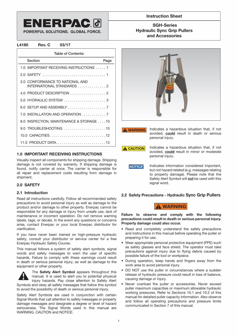
SGH-Series Hydraulic Sync Grip Pullers
and Accessories
Table of Contents:
Section Page
1.0 IMPORTANT RECEIVING INSTRUCTIONS . . . . . 1
2.0 SAFETY . . . . . . . . . . . . . . . . . . . . . . . . . . . . . . . . 1
3.0 CONFORMANCE TO NATIONAL AND INTERNATIONAL STANDARDS . . . . . . . . . . . . . . 2
4.0 PRODUCT DESCRIPTION . . . . . . . . . . . . . . . . . . 2
5.0 HYDRAULIC SYSTEM . . . . . . . . . . . . . . . . . . . . . 3
6.0 SETUP AND ASSEMBLY . . . . . . . . . . . . . . . . . . . 7
7.0 INSTALLATION AND OPERATION . . . . . . . . . . . . 7
8.0 INSPECTION, MAINTENANCE & STORAGE . . . . 10
9.0 TROUBLESHOOTING . . . . . . . . . . . . . . . . . . . . . 10
10.0 CAPACITIES . . . . . . . . . . . . . . . . . . . . . . . . . . . . 12
11.0 PRODUCT DATA . . . . . . . . . . . . . . . . . . . . . . . . . 13
1.0 IMPORTANT RECEIVING INSTRUCTIONSVisually inspect all components for shipping damage. Shipping damage is not covered by warranty. If shipping damage is found, notify carrier at once. The carrier is responsible for all repair and replacement costs resulting from damage in shipment.
2.0 SAFETY
2.1 IntroductionRead all instructions carefully. Follow all recommended safety precautions to avoid personal injury as well as damage to the product and/or damage to other property. Enerpac cannot be responsible for any damage or injury from unsafe use, lack of maintenance or incorrect operation. Do not remove warning labels, tags, or decals. In the event any questions or concerns arise, contact Enerpac or your local Enerpac distributor for clarification.
If you have never been trained on high-pressure hydraulic safety, consult your distributor or service center for a free Enerpac Hydraulic Safety Course.
This manual follows a system of safety alert symbols, signal words and safety messages to warn the user of specific hazards. Failure to comply with these warnings could result in death or serious personal injury, as well as damage to the equipment or other property.
The Safety Alert Symbol appears throughout this manual. It is used to alert you to potential physical injury hazards. Pay close attention to Safety Alert
Symbols and obey all safety messages that follow this symbol to avoid the possibility of death or serious personal injury.
Safety Alert Symbols are used in conjunction with certain Signal Words that call attention to safety messages or property damage messages and designate a degree or level of hazard seriousness. The Signal Words used in this manual are WARNING, CAUTION and NOTICE.
WARNING Indicates a hazardous situation that, if not avoided, could result in death or serious personal injury.
CAUTION Indicates a hazardous situation that, if not avoided, could result in minor or moderate personal injury.
NOTICE Indicates information considered important, but not hazard related (e.g. messages relating to property damage). Please note that the Safety Alert Symbol will not be used with this signal word.
2.2 Safety Precautions - Hydraulic Sync Grip Pullers
WARNING
Failure to observe and comply with the following precautions could result in death or serious personal injury. Property damage could also occur.
• Read and completely understand the safety precautions and instructions in this manual before operating the puller or preparing it for use.
• Wear appropriate personal protective equipment (PPE) such as safety glasses and face shield. The operator must take precautions against injury due to flying debris caused by possible failure of the tool or workpiece.
• During operation, keep hands and fingers away from the work area to avoid personal injury.
• DO NOT use the puller in circumstances where a sudden release of hydraulic pressure could result in loss of balance, causing damage or injury.
• Never overload the puller or accessories. Never exceed puller maximum capacities or maximum allowable hydraulic working pressures. Refer to Sections 10.1 and 10.2 of this manual for detailed puller capacity information. Also observe and follow all operating precautions and pressure limits communicated in Section 7 of this manual.

2
• Be aware that puller capacity will vary, depending on the puller model, configuration and other variables. In some instances, the rated capacity of the puller may be less than the rated capacity of the hydraulic cylinder.
• Never attempt to pry the puller by inserting tools or other objects between the jaws. This may cause center bolt damage.
• Use hydraulic pressure gauges to verify proper operating pressure in the hydraulic system. Do NOT exceed maximum pressure limits of the lowest rated component in your system. Always use high pressure hoses and fittings.
• It is impossible to predict the exact force needed for every pulling situation. The amount of press fit and force of removal can vary greatly between jobs. Set-up requirements along with the size, shape and condition of the parts being pulled are variables which must be considered. Study each pulling application before you select your puller.
• Do not overload equip ment. Use the correct size puller for your application. If you have applied maximum force, and the part still will not move, then use a larger capacity puller. Use of a sledge hammer to loosen parts is not recommended.
• Do not use puller if threads on adjusting rod, threaded collar or hydraulic cylinder are damaged or worn. Do not use puller if adjusting rod is bent.
• Do not over-extend the hydraulic cylinder. Do not operate the cylinder beyond the limits of its rated stroke.
• Apply force gradually. Align puller grip jaws as required. Be sure the setup is rigid and that puller is square with the work.
• Never use a puller that is damaged, altered or in need of repair.
• Always be sure that the adjusting rod is loosened and hydraulic pressure is completely relieved before performing any puller adjustment or repair procedures. Never service the puller while it is installed and under tension.
• Always read, understand and follow all safety precautions and instructions, including those that are contained within the procedures of this manual.
2.3 Additional Hydraulic Safety Precautions
WARNINGFailure to observe and comply with the following precautions could result in death or serious personal injury. Property damage could also occur.
• Do not remove or disable the pump relief valve. Never set the relief valve to a higher pressure than the maximum rated pressure of the pump.
• The puller hydraulic cylinder is designed for a maximum pressure of 10,150 psi [700 bar]. Do not connect a pump with a higher pressure rating to the cylinder.
• To avoid personal injury and equipment damage, make sure all hydraulic components are rated for at least 10,150 psi [700 bar] working pressure.
• The system operating pressure must not exceed the pressure rating of the lowest rated component in the system. Install pressure gauge(s) in the system to monitor operating pressure. It is your window to see what is happening in the system.
• Make sure that all system components are protected from external sources of damage, such as excessive heat, flame, moving machine parts, sharp edges and corrosive chemicals.
• Do not handle pressurized hoses. Escaping oil under pressure can penetrate the skin. If oil is injected under the skin, see a doctor immediately.
• Always do a visual inspection of the puller and puller hydraulic system before placing it into operation. If any problems are
found, do not use the puller. Have the equipment repaired and tested before it is returned to service.
• Never use a hydraulic cylinder that is leaking oil. Do not use a cylinder that is damaged, altered or in need of repair.
• Do not loosen plugs, relief valves or any other hydraulic components unless hydraulic pressure is completely relieved.
• Always be sure that hydraulic pressure is fully relieved before disconnecting hydraulic hoses, loosening hydraulic couplers, or performing any cylinder disassembly or repair procedures.
• Always read, understand and follow all safety precautions and instructions, including those that are contained within the procedures of this manual.
CAUTION
Failure to observe and comply with the following precautions could result in minor or moderate personal injury. Property damage could also occur.
• Avoid damaging hydraulic hose. Avoid sharp bends and kinks when routing hydraulic hoses. Using a bent or kinked hose will cause severe back-pressure. Sharp bends and kinks will internally damage the hose, leading to premature hose failure.
• Do not drop heavy objects on hose. A sharp impact may cause internal damage to hose wire strands. Applying pressure to a damaged hose may cause it to rupture.
• Do not lift hydraulic equipment by the hoses or swivel couplers. Use the carrying handle or strap.
• Keep hydraulic equipment away from flames and heat. Excessive heat will soften packings and seals, resulting in fluid leaks. Heat also weakens hose materials and packings. For optimum performance, do not expose equipment to temperatures of 150˚F [65˚C] or higher. Protect all hydraulic equipment from weld spatter.
• Immediately replace worn or damaged parts with genuine Enerpac parts. Enerpac parts are designed to fit properly and to withstand high loads. Non-Enerpac parts may break or cause the product to malfunction.
NOTICE• Hydraulic equipment must only be serviced by a qualified
hydraulic technician. For repair service, contact the Enerpac Authorized Service Center in your area.
• To help ensure proper operation and best performance, use of Enerpac oil is strongly recommended.
3.0 CONFORMANCE TO NATIONAL AND INTERNATIONAL STANDARDS
Enerpac declares that this product has been tested and conforms to applicable standards and is compatible with all CE Requirements. A copy of an
EU Declaration of Incorporation is enclosed with each shipment of this product.
4.0 PRODUCT DESCRIPTION
4.1 Sync Grip Hydraulic Puller (SGH-Series)The Sync Grip Hydraulic puller can be used to remove and install gears, bearings and pulleys.
Four different puller models in a variety of capacities are available. Refer to the documentation provided with your shipment for model numbers and additional product data.
The Sync Grip puller's synchronized closing system means that all jaws move in unison, reducing the chance of damage to the puller components and making the puller easier and safer to use.

3
4.2 Sync Grip Puller Set (GPS-Series)The Enerpac Sync Grip Puller Set includes the following items:
• Sync Grip hydraulic grip puller (SGH-Series).• Hydraulic pump, electric, air, battery or hand operated.• Hydraulic hose, 6 feet [1.8 m] long.• Hydraulic pressure gauge and gauge adapter.• Hydraulic cylinder with coupler.The specific items included in the Sync Grip Puller Set will vary, depending on the puller size and the pump type ordered.
4.3 Master Puller Set (MPS-Series)The Enerpac Master Puller Set includes all the items of the Sync Grip Puller Set plus the following additional items:
• Bearing Cup Puller Attachment• Cross Bearing Puller Components• Bearing Separator Attachment• Mounting and attaching hardwareThese attachments allow the puller to be configured as a bearing cup puller or as a cross style bearing puller. They are designed for work environments where clearance prevents a direct application of the puller jaws.
For these configurations, the grip puller jaws, puller body and self-centering mechanism are not used.
The specific items included in the Master Puller Set will vary, depending on the puller size and the pump type ordered.
5.0 HYDRAULIC SYSTEM
5.1 Hydraulic Component RequirementsAll hydraulic components used with the puller, including pump, cylinder, pressure gauge, hoses and fittings must be rated for at least 10,150 psi [700 bar] maximum working pressure.
The pump must include a safety relief valve that opens if the maximum hydraulic working pressure of 10,150 psi [700 bar] is exceeded.
WARNING Pump safety relief valve must not be set higher than 10,150 psi [700 bar]. Failure to observe this precaution could result in high pressure oil leaks and/or catastrophic failure. Serious personal injury or death could result.
Electric, air and battery powered pumps must also include a user-adjustable relief valve, allowing the user to adjust the maximum working pressure to the correct setting for the puller application. For some puller configurations and applications, this setting will be less than the pump safety relief valve setting.
This information is provided for users who may wish to use the puller with the existing hydraulic components in their shop facilities. All hydraulic components included in an Enerpac Sync Grip Puller Set or Master Puller Set will conform to the stated specifications and requirements.
5.2 Hydraulic CylinderThe hydraulic cylinder is pre-assembled in the body of the Sync Grip puller. When needed, the cylinder can be removed from the Sync Grip puller for use with various Master Puller Set components.
Refer to the following table for hydraulic cylinder usage information:
Hydraulic Cylinder Usage Information
Enerpac Cylinder
Model No.
Sync Grip Puller
Model No.
Master Puller Set Components
Cross Bearing Puller
Bearing Separator
Bearing Cup Puller
RWH121 SGH14 BHP2772 BHP181 BHP180
RCH202 SGH24 BHP262 BHP282 BHP280
RCH302 SGH36 BHP362 BHP382 BHP380
RCH603 SGH64 BHP562 BHP582 BHP580Note: Cylinder model RWH121 uses one 1/4" NPTF female coupler (Enerpac AR630). Cylinder models RCH202, RCH302 and RCH603 use one 3/8" NPTF male coupler (Enerpac CH604).
WARNING Use only the Enerpac cylinder specified for your puller model. Improper operation and/or catastrophic failure could occur if a different cylinder is used. Serious personal injury or death may result.
Sync Grip Puller
Figure 1, Hydraulic Puller Configurations (Typical)
Cross Bearing Puller and Bearing Separator
Bearing Cup Puller

4
Figure 2, Setup and Assembly - Sync Grip Puller
1
2 3 4
3
5
6
9
7
810
1
2
3
4
2
6
9
7
8103
1
5
3
4
79 3
5
6
8
10
1
2 3 4
3
5
6
9
7
810
1
2
3
4
2
6
9
7
8103
1
5
3
4
79 3
5
6
8
10
1
2 3 4
3
5
6
9
7
810
1
2
3
4
2
6
9
7
8103
1
5
3
4
79 3
5
6
8
10
Key:
1. Adjusting Rod 2. Hex Nut 3. Plate 4. Jaw, Standard Length Jaw, Extended Reach (optional) 5. Capscrew 6. Strap 7. Assembly, Self-Centering 8. Body 9. Hydraulic Cylinder 10. Mounting Screw
1
23
4
3
5
6
9
7
810
1
2
3
4
2
6
9
7810
3
1
5 34
79
3
56
8
10
1
23
4
3
5
6
9
7
810
1
2
3
4
2
6
9
7810
3
1
5 34
79
3
56
8
10
1
23
4
3
5
6
9
7
810
1
2
3
4
2
6
9
7810
3
1
5 34
79
3
56
8
10
Two-jaw Configuration (Model SGH14)
Note: Components shown in this figure are included with the GPS-Series Sync Grip Puller Set and the MPS-Series Master Puller Set.
Extended reach “long” jaws are an optional accessory for all pullers.
Three-jaw Configuration (Model SGH14)
Three-jaw Configuration (Models SGH24, SGH36 and SGH64)

5
Figure 3, Setup and Assembly - Bearing Cup Puller
1
2
3
4
5 6
7
8
8
8
10
11
12
9
1
2
3
4
5 6
7
8
8
8
10
11
12
9(Assembled View)
Key:
1. Adjusting Rod 2. Threaded Saddle 3. Hydraulic Cylinder 4. Hex Nut 5. Slide Plate 6. Slotted Crosshead 7. Leg Washer 8. Leg (various lengths) 9. Leg Reducer10. Leg End 11. Mounting Screw 12. Internal Bearing Race Puller
Note: Components shown in this figure are included with the MPS-Series Master Puller Set.

6
Figure 4, Setup and Assembly - Cross Bearing Puller
6
1
13
114
56
8
3
2
7
8
8
9
10
6
1
13
114
56
8
3
2
7
8
8
9
10
(Assembled View - With Bearing Separator)
Key:
1. Adjusting Rod 2. Threaded Saddle 3. Hydraulic Cylinder 4. Hex Nut 5. Slide Plate 6. Slotted Crosshead
7. Leg Washer 8. Leg (various lengths) 9. Leg Reducer10. Leg End 11. Mounting Screw 13. Bearing Separator Attachment
6
1
13
114
56
8
3
2
7
8
8
9
10
(Assembled View - Without Bearing Separator)
Note: Components shown in this figure are included in the MPS-Series Master Puller Set.

7
5.3 Checking Oil LevelCheck the oil level in the pump reservoir with the cylinder fully retracted. Add oil if level is low. Refer to the pump instruction sheet for detailed instructions and oil type.
Be sure to use a high quality hydraulic oil. Use of Enerpac oil is strongly recommended.
5.4 Advancing and Retracting the Cylinder• To advance: Close the pump release valve. Operate the
pump to build pressure and advance the cylinder.• To retract: Open the pump release valve to release pressure
and retract the cylinder.For detailed hydraulic component operating instructions, refer to the instruc tion sheet included with the pump, hose, pressure gauge and hydraulic cylinder. Completely observe and follow all communicated instructions and safety precautions.
5.5 Air RemovalTo remove trapped air from the hydraulic circuit, fully advance and retract the puller cylinder several times while it is not under load. If possible, position the cylinder so that it is lower than the pump reservoir. Avoid pressure build-up as the cylinder is being cycled. Air removal is complete when cylinder motion becomes smooth.
6.0 SETUP AND ASSEMBLY
6.1 Handling Large Pullers• Use a crane and slings of suitable rated capacity to lift and
unload the puller.• Know the weight of the complete puller assembly, including
puller, hydraulic cylinder and all attachments.• Be careful when lifting the puller while it is in the vertical
position, as the legs will close.• If needed, support the puller with slings so that it can be
used horizontally. When reorienting the puller from horizontal to the vertical position, incline the puller slowly and carefully.
6.2 Puller ConfigurationsThe puller may be assembled in one of three different configurations:
1) Sync Grip Puller
2) Bearing Cup Puller
3) Cross Bearing Puller
Note that components required to assemble the bearing cup puller and cross bearing puller (items 2 and 3) are included only with the Master Puller Set.
Refer to figures 2, 3 and 4 for assembly details. Refer to the following sections of this manual for detailed operation instructions for each configuration.
6.3 Jaw Arrangement - Sync Grip PullerThree standard length jaws are provided with the puller. Extended reach “long” jaws, are available as an optional accessory for all puller models.
Model SGH14 can be configured as either a two-jaw or three-jaw puller. The three-jaw configuration provides a more stable and secure grip, resulting in a more evenly distributed pulling force. For this reason, the three-jaw configuration should be used whenever possible.
Models SGH24, SGH36 and SGH64 can be assembled only in the three-jaw configuration.
7.0 INSTALLATION AND OPERATION NOTICE Before operating any high force tool equipment, it is mandatory that the operator has a full understanding of all
instructions and safety precautions included in this manual, and of all applicable local safety regulations and laws. If questions or concerns, contact the Enerpac Technical Service Department or your local Enerpac distributor.
7.1 Adjusting Rod Point ProtectorAll models feature a threaded adjusting rod with a tempered steel point.
A point protector is packed separately with all SGH-Series models. To prevent damage, the point protector MUST be used if the shaft end does not contain a drilled center hole or depression. See Figure 5.
Figure 5, Point Protector
OK
OK
POINT PROTECTOR
7.2 General Puller Use Instructions• Be sure that the puller adjusting rod is cleaned and greased
before use.• Be sure that the jaws are properly centered on the item to
be removed.• Position the point of the adjusting rod into the center hole
of the shaft or axle. If there is no center hole, use a point protector (included with all pullers).
• After mounting the puller on the part to be removed, be certain that the thread engagement indicator is visible. See Figure 6 for location. If the adjusting rod is turned clockwise too many turns, the indicator will be hidden, indicating that the amount of thread engagement is not sufficient.
WARNING
Do not operate the puller if the thread engagement indicator is not visible. Catastrophic failure could occur if the amount of thread engagement is not sufficient. Serious personal injury or death may result.
NOTICE If the thread engagement indicator is not visible, remove the puller and reinstall the jaws using the next lowest set of mounting holes.
Figure 6, Thread engagement indicator (red band)

8
• To reduce the possibility of jaw deformation, always work with the jaws installed in the lowest possible mounting holes. Use the higher mounting holes only if necessary to provide clearance around large components. See Figure 7.
Figure 7, Jaw Mounting Positions (typical)
Lowest Position (preferred)
Highest Position
• Continuously monitor the hydraulic pressure gauge while operating the pump and puller. Stop the pump immediately if the maximum allowable hydraulic pressure for your puller model and configuration is reached.
• During operation, watch the puller for indications of jaw or adjusting rod deformation. See Figure 6. If any deformation is noticed, stop the pump immediately.
• In some applications, the amount of deformation may be so small that it is not noticeable. Never rely on visible deformation to determine the puller's safe operating limits. Always monitor the hydraulic pressure gauge.
• Work slowly when operating the puller in order to prevent any sudden or unexpected displacement of parts being removed.
• If needed, use a spacer of appropriate size to reduce the possibility of adjusting rod deformation. The spacer should be a solid steel billet with flat ends and a diameter that is larger than that of the adjusting screw.
Figure 8, Checking for Deformation
7.3 Sync Grip Puller - Installation and Operation• Assemble puller components as described in Figure 2. Refer
to Section 6.2 for additional information. NOTICE Model SGH14 can be configured as either a two or three-jaw puller. The three-jaw configuration is recommended because it provides the most even distribution of pulling force.
• Refer to sections 11.1 and 11.3 for additional jaw assembly details, specifications and dimensions.
• Install the puller on the pulley or other part to be removed. See Figure 9 for examples.
• Read and understand the following hydraulic pressure warning statements before proceeding. Also refer to Section 10.1 of this manual for additional related information.
WARNING
Models SGH14, SGH24 and SGH36:
Do not exceed 5076 psi [350 bar] when using Sync Grip puller model SGH14 in the two-jaw configuration.
Do not exceed 10,150 psi [700 bar] when using Sync Grip puller model SGH14 in the three-jaw configuration.
Do not exceed 10,150 psi [700 bar] when using Sync Grip puller models SGH24 and SGH36.
Overloading and catastrophic failure could occur if the stated maximum pressure limit for your puller model and configuration is exceeded. Serious personal injury or death may result.
WARNING
MODEL SGH64 Only:
Do not exceed 7850 psi [540 bar] when using Sync Grip puller model SGH64.
Overloading and catastrophic failure could occur if this maximum pressure limit is exceeded. Serious personal injury or death may result.
Be aware that for model SGH64, the puller maximum rated capacity is approximately 25 percent less than the cylinder maximum rated capacity. For this reason, use extreme care to avoid exceeding the 7850 psi [540 bar] pressure limit during puller operation.
Two-Jaw Configuration (Model SGH14 only)
Three-Jaw Configuration (all models)
Figure 9, Pulley Removal (typical)

9
• Connect pump and hose to the puller hydraulic cylinder. Be sure that a pressure gauge is installed in the circuit.
• Gradually apply hydraulic pressure to remove the part. Continuously monitor the pressure gauge to avoid exceeding the allowable maximum working pressure for your setup.
7.4 Cross Bearing Puller - Installation and Operation• Assemble puller components as described in Figure 4.• Install the puller on the bearing, pulley or other item to be
removed. Align puller legs. See Figure 10.• If needed for your application, install the bearing separator
attachment. Refer to Section 7.5.• Read and understand the following warning statement before
proceeding. Also refer to Section 10.2 of this manual for important maximum hydraulic working pressure information.
WARNING
Do not exceed the stated maximum hydraulic working pressure for the cross bearing puller model being used.
Refer to Section 10.2 of this manual for the maximum hydraulic working pressure applicable to your cross bearing puller model. Be aware that the cross bearing puller is rated at a lower maximum capacity than the hydraulic cylinder.
Overloading and catastrophic failure could occur if the stated maximum pressure limit is exceeded. Serious personal injury or death may result.
• Connect pump and hose to the puller hydraulic cylinder. Be sure that a pressure gauge is installed in the circuit.
• Gradually apply hydraulic pressure to remove the part. Continuously monitor the pressure gauge to avoid exceeding the allowable maximum working pressure for your setup.
Figure 10, Cross Bearing Puller (typical)
7.5 Bearing Separator Attachment
In situations where limited work room prevents a direct application of the grip puller jaws, the bearing separator attachment can be used in combination with the cross bearing puller.
The bearing separator attachment contains wedge shaped edges, allowing it to be more easily positioned behind a difficult-to-reach bearing, pulley or other shaft-mounted component. It has two halves, each containing a “flat” side and a “recessed” side.
Whenever possible, it is recommended that the attachment be installed in the “A” orientation, as shown in Figure 11, so that the flat side of each separator half is positioned against
the part to be removed. This will help spread the load over a greater surface area, reducing the possibility of deformation.
However, for applications where work room is especially limited, it may be necessary to begin the pulling process with the attachment installed in the “B” orientation, as shown in Figure 12. In this orientation, the recessed side of each separator half is positioned against the part to be removed.
After the part has been moved a sufficient distance on the shaft, the attachment should be reinstalled in the “A” orientation. The removal process can then be fully completed.
When using the bearing separator attachment, follow the instructions and precautions contained in Section 7.4 of this manual. Also refer to Section 10.2 for maximum rated capacities and related information.
Figure 11, Bearing Separator Attachment - “A” Orientation (typical)
Figure 12, Bearing Separator Attachment - “B” Orientation (typical)

10
7.6 Bearing Cup Puller - Installation and Operation• Assemble puller components as shown in Figure 3.• Install the puller on the bearing to be removed. Align puller
legs and bearing cup puller jaws. See Figure 12.• Read and understand the following warning statement
before proceeding. Also refer to Section 10.2 of this manual for important maximum hydraulic working pressure information.
WARNING
Do not exceed the stated maximum hydraulic working pressure for the bearing cup puller model being used.
Refer to Section 10.2 of this manual for the maximum hydraulic working pressure applicable to your bearing cup puller model. Be aware that the bearing cup puller is rated at a lower maximum capacity than the hydraulic cylinder.
Overloading and catastrophic failure could occur if the stated maximum pressure limit is exceeded. Serious personal injury or death may result.
• Connect pump and hose to the puller hydraulic cylinder. Be sure that a pressure gauge is installed in the circuit.
• Gradually apply hydraulic pressure to remove the bearing. Continuously monitor the pressure gauge to avoid exceeding the allowable maximum working pressure for your setup.
Figure 12, Cross Bearing Puller with Bearing Cup Attachment (typical)
8.0 INSPECTION, MAINTENANCE & STORAGEMaintenance is required when wear or leakage is noticed. Periodically inspect all components to detect any problem requiring maintenance or service.
• Periodically check the hydraulic system for loose connections, leaks and other obvious problems. Replace any damaged components immediately.
• Monitor the oil temperature during operation. Do not exceed oil temperatures of 140°F [60°C].
• Keep all hydraulic components clean.• Keep the puller in good condition. Clean and lubricate the
puller’s adjusting rod and puller legs frequently, from thread to tip, to ensure good operation and long life.
• Change the hydraulic oil in your system as recom mended in the pump instruction sheet. Use of Enerpac oil is strongly recommended.
• Periodically check the puller for any bent, loose, worn or deformed components. Make repairs as required before using the puller.
• Store the puller in a clean, dry and secure location. Keep stored hydraulic cylinders and hoses away from heat and direct sunlight.
• If the puller requires repairs, refer to the Enerpac website for the repair parts sheet applicable to your puller model.
NOTICE Hydraulic equipment must only be serviced by a qualified hydraulic technician. For repair service, contact the Enerpac Authorized Service Center in your area.
9.0 TROUBLESHOOTINGRefer to the troubleshooting guide (see next page) when diagnosing puller operational problems. Please note that the troubleshooting guide is not all-inclusive, and should be considered only as an aid to help diagnose the most commonly anticipated problems.
For repair service, contact your nearest Enerpac Authorized Service Center. As required, also refer to the troubleshooting information provided with the hydraulic pump and cylinder.

11
Troubleshooting Guide, SGH-Series Sync Grip Pullers
Puller Mechanical Troubleshooting
Symptom Possible Cause Solution
1. Jaws do not move freely or are difficult to move.
Self-centering mechanism corroded or seized. Inspect self-centering mechanism. If corroded or seized, apply penetrating oil. Dismantle and clean mechanism as required.
2. One jaw moves independently.
Self-centering strap damaged or broken. Replace self-centering strap.
Replace complete self-centering mechanism if needed.
3. Adjusting rod will not turn or requires excessive effort to turn.
a. Corroded threads on adjusting rod, cylinder or threaded saddle.
If parts are seized, apply penetrating oil.
Inspect threads on adjusting rod, cylinder and threaded saddle. Dismantle and clean components as required.
b. Worn or damaged threads. Replace adjusting rod, hydraulic cylinder and/or threaded saddle as required.
Do not use puller if threads are worn or damaged.
c. Adjusting rod is bent. Replace adjusting rod.
Do not use puller if adjusting rod is bent.
Hydraulic System Troubleshooting
Symptom Possible Cause Solution
1. Cylinder will not advance.
a. Pump release valve open. Close pump release valve.
b. Pump oil level is low. Add oil to pump reservoir as required.
c. Air in hydraulic system. Remove air from hydraulic system. Refer to Section 5.5.
d. Couplers not fully tightened. Tighten couplers.
e. Blocked hydraulic hose. Repair or replace hydraulic hose.
f. Pump malfunctioning. Repair or replace pump as required.
g. Cylinder seals leaking. Repair or replace cylinder.
2. Cylinder advances only part way.
a. Pump oil level is low. Add oil to pump reservoir as required.
b. Couplers not fully tightened. Tighten couplers.
c. Cylinder plunger binding. Repair or replace cylinder.
3. Cylinder advances erratically.
a. Air in hydraulic system. Remove air from hydraulic system. Refer to Section 5.5.
b. Cylinder plunger binding. Repair or replace cylinder.
4. Cylinder advances more slowly than normal.
a. Leaking connection. Repair leaking connection.
b. Couplers not fully tightened. Tighten couplers.
c. Pump malfunctioning. Repair or replace pump as required.
5. Cylinder advances, but will not hold.
a. Cylinder seals leaking. Repair or replace cylinder.
b. Leaking or loose connection. Repair leaking connection.
c. Pump malfunction. Repair or replace pump.
6. Cylinder leaks oil. a. Leaking or loose connection. Repair leaking connection.
b. Worn or damaged cylinder plunger. Repair or replace cylinder.
c. Internal leakage. Repair or replace cylinder.
7. Cylinder will not retract or retracts more slowly than normal.
a. Pump release valve closed. Open pump release valve.
b. Coupler not fully tightened. Tighten coupler.
c. Pump reservoir is overfilled. Drain oil from pump reservoir as required.
d. Blocked hydraulic hose. Repair or replace hydraulic hose.
e. Internal cylinder damage. Repair or replace cylinder.
12
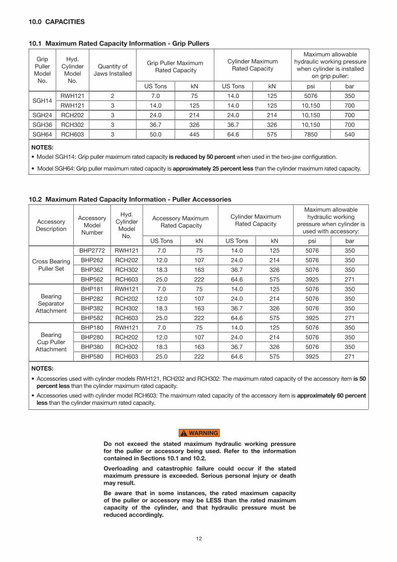
10.1 Maximum Rated Capacity Information - Grip Pullers
Grip Puller Model
No.
Hyd. Cylinder Model
No.
Quantity of Jaws Installed
Grip Puller Maximum Rated Capacity
Cylinder Maximum Rated Capacity
Maximum allowable hydraulic working pressure when cylinder is installed
on grip puller:
US Tons kN US Tons kN psi bar
SGH14RWH121 2 7.0 75 14.0 125 5076 350
RWH121 3 14.0 125 14.0 125 10,150 700
SGH24 RCH202 3 24.0 214 24.0 214 10,150 700
SGH36 RCH302 3 36.7 326 36.7 326 10,150 700
SGH64 RCH603 3 50.0 445 64.6 575 7850 540
NOTES:
• Model SGH14: Grip puller maximum rated capacity is reduced by 50 percent when used in the two-jaw configuration.
• Model SGH64: Grip puller maximum rated capacity is approximately 25 percent less than the cylinder maximum rated capacity.
10.2 Maximum Rated Capacity Information - Puller Accessories
Accessory Description
Accessory Model
Number
Hyd. Cylinder Model
No.
Accessory Maximum Rated Capacity
Cylinder Maximum Rated Capacity
Maximum allowable hydraulic working
pressure when cylinder is used with accessory:
US Tons kN US Tons kN psi bar
Cross Bearing Puller Set
BHP2772 RWH121 7.0 75 14.0 125 5076 350
BHP262 RCH202 12.0 107 24.0 214 5076 350
BHP362 RCH302 18.3 163 36.7 326 5076 350
BHP562 RCH603 25.0 222 64.6 575 3925 271
Bearing Separator
Attachment
BHP181 RWH121 7.0 75 14.0 125 5076 350
BHP282 RCH202 12.0 107 24.0 214 5076 350
BHP382 RCH302 18.3 163 36.7 326 5076 350
BHP582 RCH603 25.0 222 64.6 575 3925 271
Bearing Cup Puller Attachment
BHP180 RWH121 7.0 75 14.0 125 5076 350
BHP280 RCH202 12.0 107 24.0 214 5076 350
BHP380 RCH302 18.3 163 36.7 326 5076 350
BHP580 RCH603 25.0 222 64.6 575 3925 271
NOTES:
• Accessories used with cylinder models RWH121, RCH202 and RCH302: The maximum rated capacity of the accessory item is 50 percent less than the cylinder maximum rated capacity.
• Accessories used with cylinder model RCH603: The maximum rated capacity of the accessory item is approximately 60 percent less than the cylinder maximum rated capacity.
10.0 CAPACITIES
WARNING
Do not exceed the stated maximum hydraulic working pressure for the puller or accessory being used. Refer to the information contained in Sections 10.1 and 10.2.
Overloading and catastrophic failure could occur if the stated maximum pressure is exceeded. Serious personal injury or death may result.
Be aware that in some instances, the rated maximum capacity of the puller or accessory may be LESS than the rated maximum capacity of the cylinder, and that hydraulic pressure must be reduced accordingly.

13
B
B
AA
11.1 Specifications and Dimensions - Grip Puller Reach, Spread and Weights
11.0 PRODUCT DATA
Grip Puller Model
No.
Jaw Length
Maximum Reach Maximum Spread Weight *A B
lb Kgin mm in mm
SGH14Std. 12.60 320 13.78 350 55.1 25
Long 15.75 400 15.94 405 59.5 27
SGH24Std. 12.60 320 18.90 480 108.0 49
Long 17.13 435 21.26 540 114.6 52
SGH36Std. 16.14 410 25.59 650 165.3 75
Long 20.67 525 28.35 720 178.5 81
SGH64Std. 27.56 700 38.58 980 268.9 122
Long 33.46 850 42.52 1080 288.8 131
* Approximate weight of assembled puller, including body, adjusting rod, jaws and hydraulic cylinder.
Refer to Section 11.2 for adjusting rod and point protector dimensions.
Standard Length JawsExtended Reach “Long” Jaws
(Optional Accessory)
B
B
AA

14
11.2 Specifications and Dimensions - Adjusting Rod and Point Protector
Used with Grip Puller Model No.
Total Length Thread Length Thread Size Diameter Height
L N R d D H
in mm in mm in mm in mm in mm
SGH14 15.75 400 8.74 222 3/4" -16 UNF 0.83 21.0 1.50 38 0.65 16.5
SGH24 26.38 670 13.70 348 1" - 8 UNC 1.26 32.0 1.57 40 0.67 17
SGH36 31.10 790 16.81 427 1-1/4" - 7 UNC 1.50 38.0 1.73 44 0.71 18
SGH64 38.39 975 20.87 530 1-5/8" - 5.5 UNS 1.50 38.0 1.73 44 0.71 18
Used with Grip Puller Model No.
Jaw Length
End Surface Width Total Thickness Length Distance Between Holes
P R E L D
in mm in mm in mm in mm in mm
SGH14Std. 0.59 15.0 0.98 25.0 0.49 12.5 17.17 436 3.27 83
Long 0.59 15.0 0.98 25.0 0.49 12.5 20.31 516 3.27 83
SGH24Std. 0.69 17.5 1.22 31.0 0.61 15.5 21.65 550 4.53 115
Long 0.69 17.5 1.22 31.0 0.61 15.5 26.18 665 4.53 115
SGH36Std. 0.94 24.0 1.61 41.0 0.87 22.0 27.48 698 4.92 125
Long 0.94 24.0 1.61 41.0 0.87 22.0 32.40 823 4.92 125
SGH64Std. 1.06 27.0 1.97 50.0 1.18 30.0 41.73 1060 5.91 150
Long 1.06 27.0 1.97 50.0 1.18 30.0 47.64 1210 5.91 150
11.3 Specifications and Dimensions - Grip Puller Jaws
R
L
Nd
H
D2
60°
E D
L
P
E D
R
L
P
R
E D
L
P
E D
R
L
P
R
Extended Reach “Long” JawsStandard Length Jaws

15
V1, V2
W
X
X
11.4 Specifications and Dimensions - Bearing Cup Puller Attachment
Bearing Cup Puller Attachment
Model
Used with Enerpac Master
Puller Set
Spread Min. Spread Max. Length Thread SizeWeight
S1 S2 T T2 U
in mm in mm in mm in mm lb Kg
BHP180 MPS14 1.6 40 5.7 145 4.5 115 9.3 237 3/4" -16 UNF 4.4 2.0
BHP280 MPS24 1.3 32 6.3 160 5.5 140 10.5 266 1" - 8 UNF 5.3 2.4
BHP380 MPS36 2.4 60 9.4 240 5.9 150 12.2 310 1-1/4" - 7 UNC 13.2 6.0
BHP580 MPS64 2.4 60 9.4 240 5.9 150 12.2 310 1-5/8" - 5.5 UNS 14.1 6.4
S1, S2
T1
T2
U
11.5 Specifications and Dimensions - Bearing Separator Attachment
Bearing Separator
Attachment Model
Used with Enerpac Master
Puller Set
Spread Min. Spread Max. Width Thread SizeWeight
V1 V2 W X
in mm in mm in mm lb Kg
BHP181 MPS14 0.39 10 4.33 110 4.33 110 5/8" - 18 UNF 6.0 2.7
BHP282 MPS24 0.47 12 5.28 134 6.10 155 5/8" - 18 UNF 12.6 5.7
BHP382 MPS36 0.67 17 9.84 250 10.24 260 1" - 14 UNS 62.8 28.5
BHP582 MPS64 0.67 17 9.84 250 10.24 260 1-1/4" - 12 UNF 62.8 28.5

Australia and New ZealandActuant Australia Ltd.
Block V Unit 3
P.O. Box 6867Wetherhill Park, NSW 1851
Regents Park Estate391 Park RoadRegents Park NSW 2143AustraliaT +61 287 177 200 F +61 297 438 648 [email protected]
Brazil Power Packer do Brasil Ltda.Rua Luiz Lawrie Reid, 54809930-760 - Diadema (SP) - BrazilT +55 11 5687 2211Toll Free: 0800 891 [email protected]
ChinaActuant (China) Industries Co. Ltd.No. 6 Nanjing East Road,Taicang Economic Dep ZoneJiangsu, ChinaT +86 0512 5328 7500 F +86 0512 5335 9690Toll Free: +86 400 885 [email protected]
France, Switzerland, North Africa and French speaking African countriesENERPAC Une division d’Actuant France S.A.SZone Orlytech Bâtiment 5161 allée du commandant MouchotteCS 4035191550 Paray-Vieille-PosteFranceT +33 1 60 13 68 68F +33 1 69 20 37 [email protected]
Germany and AustriaActuant GmbH P.O. Box 300113D-40401 DüsseldorfWillstätterstrasse 13D-40549 Düsseldorf, GermanyT +49 211 471 490F +49 211 471 49 [email protected]
IndiaActuant India Private Limited No. 10, Bellary Road, Sadashivanagar,Bangalore, Karnataka 560 080IndiaT [email protected]
ItalyENERPAC S.p.A.Via Canova 420094 Corsico (Milano)T +39 02 4861 111F +39 02 4860 [email protected]
JapanApplied Power Japan LTD KKBesshocho 85-7Kita-ku, Saitama-shi 331-0821, JapanT +81 48 662 4911F +81 48 662 [email protected]
Middle East, Egypt and LibyaENERPAC Middle East FZE Plot M00737m 1242nd StreetJebel Ali Free Zone NorthP.O. Box 18004, Dubai
United Arab EmiratesT +971 (0)4 8872686F +971 (0)4 [email protected]
RussiaRep. o§ce EnerpacRussian FederationAdmirala Makarova Street 8125212 Moscow, RussiaT +7 495 98090 91F +7 495 98090 [email protected]
NorwaySales O§ce Norway Unit 524, Nydalsveien 28, 0484 OsloP.O. Box 4814, Nydalen 0422 OsloNorwayT +47 91 578 [email protected]
Southeast Asia, Hong Kongand TaiwanActuant Asia Pte Ltd.83 Joo Koon Circle Singapore 629109T +65 68 63 0611F +65 64 84 5669
South KoreaActuant Korea Ltd.3Ba 717, Shihwa Industrial ComplexJungwang-Dong, Shihung-Shi, Kyunggi-DoRepublic of Korea 429-450T +82 31 434 4506F +82 31 434 [email protected]
Spain and PortugalENERPAC SPAIN, S.L. Avda. Valdelaparra N° 27 3ª - L828108 Alcobendas (Madrid), SpainT +34 91 884 86 06F +34 91 884 86 [email protected]
Sweden, DenmarkFinland and IcelandEnerpac Scandinavia ABKopparlundsvägen 14,721 30 VästeråsSwedenT +46 (0) 771 [email protected]
The Netherlands, Belgium, Luxembourg,Central and Eastern Europe, Baltic States, Greece, Turkey and CIS countriesENERPAC B.V.Galvanistraat 115, 6716 AE EdeP.O. Box 8097, 6710 AB Ede The NetherlandsT +31 318 535 911 F +31 318 535 [email protected]
Enerpac Integrated Solutions B.V.Spinelstraat 15, 7554 TS HengeloP.O. Box 421, 7550 AK Hengelo The NetherlandsT +31 74 242 20 45F +31 74 243 03 [email protected]
South Africa and other English speaking African countriesEnerpac Africa Pty Ltd.No. 5 Bauhinia AvenueCambridge O§ce ParkBlock EHighveld Techno ParkCenturion 0157Republic of South Africa T: +27 12 940 [email protected]
United Kingdom and IrelandENERPAC UK Ltd.5 Coopies FieldMorpeth, NorthumberlandNE61 6JR, EnglandT +44 1670 5010 00 [email protected]
USA, Latin America and CaribbeanENERPAC World Headquarters P.O. Box 3241Milwaukee WI 53201-3241 USA
T +1 262 293 1600F +1 262 293 7036User inquiries:T +1 800 433 2766Distributor inquiries/orders:T +1 800 558 0530F +1 800 628 0490Technical inquiries:[email protected]@enerpac.com
Enerpac Worldwide Locations e-mail: [email protected] internet:
www.enerpac.com
090116
50 00
N86 W12500 Westbrook Crossing Menomonee Falls, Wisconsin 53051
Toll Free: +1800 363 7722
(Taicang)
+91 80 3928 9000
All Enerpac products areguaranteed against defectsin workmanship and materialsfor as long as you own them.
For the location of your nearestauthorized Enerpac Service Center,visit us at www.enerpac.com