wap-0011a wireless lan access point - solwise ltd
TRANSCRIPT

WAP-0011A Wireless LAN Access Point
User Manual Version: 1.1 (Dec. 2003)

Copyright Copyright � 2001 by this company. All rights reserved. No part of this publication may be reproduced, transmitted, transcribed, stored in a retrieval system, or translated into any language or computer language, in any form or by any means, electronic, mechanical, magnetic, optical, chemical, manual or otherwise, without the prior written permission of this company This company makes no representations or warranties, either expressed or implied, with respect to the contents hereof and specifically disclaims any warranties, merchantability or fitness for any particular purpose. Any software described in this manual is sold or licensed "as is". Should the programs prove defective following their purchase, the buyer (and not this company, its distributor, or its dealer) assumes the entire cost of all necessary servicing, repair, and any incidental or consequential damages resulting from any defect in the software. Further, this company reserves the right to revise this publication and to make changes from time to time in the contents hereof without obligation to notify any person of such revision or changes. All brand and product names mentioned in this manual are trademarks and/or registered trademarks of their respective holders. R&TTE Compliance Statement This equipment complies with all the requirements of DIRECTIVE 1999/5/CE OF THE EUROPEAN PARLIAMENT AND THE COUNCIL of March 9, 1999 on radio equipment and telecommunication terminal Equipment and the mutual recognition of their conformity (R&TTE) The R&TTE Directive repeals and replaces in the directive 98/13/EEC (Telecommunications Terminal Equipment and Satellite Earth Station Equipment) As of April 8, 2000. Safety This equipment is designed with the utmost care for the safety of those who install and use it. However, special attention must be paid to the dangers of electric shock and static electricity when working with electrical equipment. All guidelines of this and of the computer manufacture must therefore be allowed at all times to ensure the safe use of the equipment. EU Countries Intended for Use The ETSI version of this device is intended for home and office use in Austria Belgium, Denmark, Finland, France, (with Frequency channel restrictions) Germany, Greece, Ireland, Italy, Luxembourg, the Netherlands, Portugal, Spain, Sweden, and the United Kingdom. The ETSI version of this device is also authorized for use in EFTA member states: Iceland, Liechtenstein, Norway, and Switzerland. EU Countries Not intended for use None. Potential restrictive use France: Only channels 10, 11, 12, and 13

Manual Contents Chapter 1 Introduction ........................................................................................................ 4 Chapter 2 Hardware Installation ...................................................................................... 5 Chapter 3 Configuring the Wireless LAN Access Point via your browser...................... 6
3.1 System....................................................................................................................... 6 3.2 Web Pages Overview................................................................................................ 6 3.3 Configuration ............................................................................................................ 6
3.3.1 Beginning........................................................................................................... 6 3.3.2 System................................................................................................................ 6 3.3.3 LAN Wireless .................................................................................................... 7 3.3.4 Reset to default .................................................................................................. 8
Chapter 4 Using the APM Utility to configure the WAP-011A .................................... 10 4.1 Installing the APM Utility ...................................................................................... 10 4.2 Configuring the Wireless LAN Access Point ......................................................... 12
Chapter 5 Technical Specification ................................................................................. 19 Chapter 6 Troubleshooting............................................................................................. 20
Chapter 7 Appendix................................................................................................ 21
Chapter 8 Glossary .................................................................................................. 23

Chapter 1 Introduction Thank you for purchasing the Wireless LAN Access Point. This device features the innovating wireless technology that can help you build a wireless network easily! Please follow the step-by-step instructions. The manual will guide you through the driver installation and utility configuration. Package Contents ● Wireless LAN Access Point ● AC Power Adapter ● Stand Kit ● Rubber Foot*4 ● Installation Software CD (Driver & Utility + User Manual) ● Quick Installation Guide If any of the above is missing, please contact your supplier. System Requirements ● PC-compatible desktop computer or laptop with one available Ethernet port. ● Operating System: Windows 98/Me/2000/XP, with TCP/IP protocol. ● Minimum Disk Space: 10MB for utility and driver installation. Safety Precaution Only use the accessories in the device package. Otherwise, the device may not function. If you accidentally lose or damage any item, please contact your supplier. Product Features ● Interoperable with IEEE 802.11b (DSSS) 2.4GHz-Compliant Equipment ● Up to 11 Mbps High-Speed Data Transfer Rate ● Four operation modes selectable: AP / AP Client / Wireless Bridge ● 64 bit or 128 bit Wired Equivalent Privacy (WEP) Encryption ● Mac Address Filtering ● Supports up to 64 users ● Auto Fall-Back Data Rate for Long-Distance Communication and Noisy Environments ● Auto Scanning and Roaming ● Seamless and Real-time connection ● Free Software Driver Upgrades

Chapter 2 Hardware Installation Hardware Installation Procedure A. Locate an optimum location for the Wireless LAN Access Point (AP). The best place for your AP is usually the center of your wireless network, with line of sight to all of your mobile stations. B. Fix the direction of the antennas. Try to place the AP in a position that can best cover your wireless network. Normally, the higher you place the antenna, the better the performance will be. The antenna’s position enhances the receiving sensitivity. C. Connect one end of the RJ-45 (Ethernet) cable to the AP and the other end to a switch or hub. AP will then be connected to the 10 Mbps Network. D. Connect the AC Power Adapter to the AP. E. Power on the AP.

Chapter 3 Configuring the Wireless LAN Access Point via your browser The easiest way to configure the WAP-011AS AP is using the web based configuration. To use this technique simple setup the IP address of your computer to the same subnet as the default IP address of the AP. The default AP address is 192.168.1.1 so your computer could, for example, be set to 192.168.1.2. Then goto your browser and enter the address of the AP on the address line (i.e. 192.168.1.1). Press enter and the login screen for the AP should display. By default the password is no password. Then enter the configuration.
3.1 System ● Requirements 1) Desktop PC or notebook PC with a web page browser. 2) The IP address of the AP. 3) The user name and password for configuring the AP.
3.2 Web Pages Overview ● System 1) System Time 2) Administrator Settings 3) Firmware Upgrade 4) Configuration Tools 5) Status 6) System Log 7) Reset ● LAN Wireless 1) IP Config 2) Wireless Operation 3) Authorized 4) Connect Client 5) Security
3.3 Configuration In order to set Access Point you must connect to web. (Default IP: 192.168.1.1)
3.3.1 Beginning In order to start using/configuring the AP you must enter a password to let you use it. (Default no password)
3.3.2 System
3.3.2.1 System Time Connecting to a Simple Network Time Protocol (SNTP) server allows the AP to synchronize the

system clock to the global Internet. The synchronized clock in the AP is used to record the security log and control client filtering.
3.3.2.2 Administrator Settings Set a password to restrict management access to the AP. If you want to manage the AP from a remote location, (outside of the local network) you must also specify the IP address of the remote PC.
3.3.2.3 Firmware Upgrade Enter the path and name of the upgrade file then click the APPLY button below. You will be prompted to confirm the upgrade
3.3.2.4 Configuration Tools Use the "Backup Settings" tool to save the AP's current configuration to a file named "config.bin" on your PC. You can then use the "Restore Settings" tool to restore the saved configuration of the AP. Alternately, you can use the "Restore to Factory Defaults" tool to force the AP to perform reset and restore the original factory settings
3.3.2.5 Status You can use the Status screen to see the connection status for the APs' interfaces, firmware and hardware version numbers, and the number of connected clients to your network.
3.3.2.6 System Log View any attempts that have been made to gain access to your network.
3.3.2.7 Reset In the event that the AP stops responding correctly or in some way stops functioning, you can perform a reset. Your settings will not be changed. To perform the reset, click on the "Reset" button below. You will be asked to confirm your decision. The reset will be complete when the power light stops blinking.
3.3.3 LAN Wireless
3.3.3.1 IP Config The AP can be connected to your service provider in any of the following ways: ● Dynamic IP Address: Obtain an IP address automatically from your service provider. ● Static IP Address: Uses a static IP address. Your service provider gives a static IP address to access Internet services.
3.3.3.2 Wireless Operation You can configuration wireless settings about Channel ID, ESSID....etc.
3.3.3.3 Authorized You can block certain client PCs accessing the Internet based on MAC addresses.
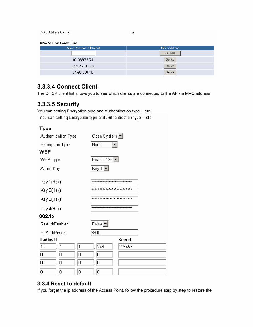
3.3.3.4 Connect Client The DHCP client list allows you to see which clients are connected to the AP via MAC address.
3.3.3.5 Security You can setting Encryption type and Authentication type ...etc.
3.3.4 Reset to default If you forget the ip address of the Access Point, follow the procedure step by step to restore the

default ip address. 1) power on the Access Point, wait 1 minute. 2) Press and hold the reset button for at least 5 seconds. The wireless lan LED will be turned off when the default action has been recognized. 3) Wait for 10 seconds so that AP can restore it’s default value. 4) reset the ap, the ip address of AP will be 192.168.1.1 right now.

Chapter 4 Using the APM Utility to configure the WAP-011A Included on CD there is a also a setup Application utility (APM Utilility). The only usefull aspect of this ulitiliy is if you change the IP address of the WAP-011A and foreget what you’ve changed it to! The APM has a search facility for this eventuality.
4.1 Installing the APM Utility A. Power on your computer and allow Window 98/Me/2000/XP to load fully. Insert the driver
CD into the CD-ROM and execute the “Setup.exe” program. (It may be found in the APM folder.) The wizard box will then appear, click “Next” to continue.
Figure 1
B. Click “Browse” to choose the folder where you want to locate the driver, click “Next”.

C. After Windows finishes copying files, it will show that “Setup has finished installing APManager on your computer.” Click “Finish” to complete the procedure.

D. Connect the AP to the Ethernet port and boots up the APM utility to start the configuration.
4.2 Configuring the Wireless LAN Access Point On the Windows Start Menu, choose “Start Programs” -> “APManager” Using this option you can directly connect to the AP. ● Find the AP 1) This submenu allows you to find and connect to the AP without knowing its IP address. Click “Discovery” in order to find the AP. Window appears indicating the IP Address of the AP and select “IP Address”. Then click “Configuration” to configure the AP. Note: In order to find Access Point, Access Point and computers must resident in the same subnet. The default IP of Access Point is “192.168.1.1”. You will also need to set your IP address of your PC to “192.168.x.x” and subnet to “255.255.0.0”.
2) It indicates a successful connection to AP if the dialog below appears. Enter password and press “OK”. (Default Password : private)
3) It indicates an unsuccessful connection to AP if the below error message appears. Please check whether the AP has an appropriate IP address and has been connected to the network.

● Table Menu The table menu contains the following enabled submenus:
1) System:
• Device Information:show the description, Mac address, Regulation Domain. • Administrator Password:change the password that APM control AP. • Profile Name List:Using “Add/Save” button to add new profile name using “Load”,
“Save”, “Del” button to modify the profile name. • Update F/W:Click the button to update the firmware of AP. Click “Browser” to choose
.dlf firmware, then click “Upgrade” button to update firmware.
• Load Default:Click the button to assign the default data. • Reset:Click the button to reset the AP. • Refresh:Click the button to reload the data from AP. • Apply:Click the button to assign new data to AP.

2) IP Config:
In this page you can see and change the IP Address, IP Mask and Gateway of the AP.
3) Statistic:
In this page you can see the statistic of the AP linking in Ethernet or Wireless. Wireless LAN
4) Wireless Operation:

Using this option you can either view or modify the Wireless LAN parameters of the AP. These parameters are described below:
o Wireless Setting: �Reject broadcast probe: When checked the AP broadcasts the ESSID to the stations, if not checked then the stations must know the AP ESSID in advance. �Channel ID: There are 14 channels available. The channels differ from country to country. Select the channel to be used. �ESSID: It is an ASCII string up to 32 characters used to identify a WLAN that prevents the unintentional merging of two co-located WLANs. The ESSID value must be the same in all stations and AP in the extended WLAN. Select the ESSID to be used. �Device Name: The name of the AP. �Rate: By default the unit adaptively selects the highest possible rate for transmission. Select the Basic & Data rates to be used among the following options: 1, 2, 5.5, 11(Mbps). �Preamble Type (Short / Long): Preamble is the first sub-field of the PPDU. It’s an appropriable frame format for transmission between PHY (Physical layer). There are two preamble types: short and long. The Short Preamble option improves throughput performance. �Beacon Interval: Set the Beacon Period parameter, which specifies the duration between Beacon packets (milliseconds). The range for the Beacon Period is between the range 20-1000 with a typical value of 100. �RTS Threshold: Minimum packet size to require an RTS Request To Send. For packets smaller than this threshold, an RTS is not sent and the packet is transmitted directly to the WLAN. This is the option for the RTS Threshold activation. �Frag. Threshold: The size at which packets will be fragmented. Choose a setting within a

range of 256 to 2346 bytes. o Operation Mode:
�Access Point: This mode provides access from Wireless Stations to Wired LANs and from Wired LANs to Wireless Stations. Furthermore, Wireless Stations within the range of the AP device may communicate with each other via the AP. �Access Point Client: This mode allows the connection of one or more remote LANs with a central LAN, creating thus an extended single virtual LAN. In this way, any station of the Remote LAN can successfully communicate with any station of the central LAN, as if all of them belonged to the same physical LAN. Wireless Stations can’t be associated with AP Clients. The AP conducts the designated traffic to the appropriate Wired or Wireless Station. �Preferred BSS: It is enabled if you select the AP Client option. BSS corresponds to the MAC Address of the desired AP.
�Wireless Bridge: The Wireless Bridge can communicate with any Wireless Bridge available in the same channel. When the Authorization Algorithm, is enabled, the Wireless Bridge can communicate with any Wireless Bridge whose BSSID exists. Note: The two Wireless Bridges must operate in the same channel and need to connect the same Access Point.

�Authorized : For security reasons the AP can use the Authorization Table option. The AP allows/denies authentication only to stations with MAC addresses contained in the Authorization List.
5) Security:

�Type:Under “Auth.” the following five options are available: – Open System : WEP is disable. – Shard Key:If select “Shard Key”, the user needs to set the Default Key to be used. Enable the WEP (Wired Equivalent Privacy) option in order to activate WEP encryption for transmissions between the stations and the AP. WEP is an authentication algorithm which protects authorized Wireless LAN users against eavesdropping. – Both Type:Mixed the “Open System” and “Shard Key” Environment. – 802.1x With EAP:it is activated the 802.1x support of the AP and the stations that will try to connect to this AP must support 802.1x as well. �ReAuthEnabled : Enable/Disable the ReAuthPeriod. �ReAuthPeriod : Set the time in seconds for the broadcast key renewal. �Radius IP : Set the IP address of the Radius Server. �Secret : Set the password used between the AP and the Radius Server.

Chapter 5 Technical Specification ● Standard: IEEE 802.11b ● Signal Type: DSSS (Direct Sequence Spread Spectrum) ● Modulation: QPSK / BPSK / CCK ● Frequency Band: 2.4 GHz ● Channel: 11 Channels (US, Canada) 13 Channels (Europe) 14 Channels (Japan) ● Data Rate: Up to 11Mbps ● Data Encryption: 64 bit / 128 bit WEP Encryption ● Transmission Range: Outdoor: 200M @10M Indoor: 50M @10M ● Compatibility: Windows 98 / Me / 2000 / XP ● Operation Mode: AP / AP Client / Wireless Bridge ● Port: One RJ 45 ● Ethernet Interface: IEEE802.3 / IEEE802.3u (10BASE-T / 100BASE-TX) ● Antenna: External Dipole Antenna ● LED Indicators: Power, Link Status, Activity Status ● Power Consumption: Tx power consumption < 900mA Rx power consumption < 600mA ● AC Adapter: Input: AC 100-240V, 50-60Hz Output: DC 5V /2A ● Temperature: Operating: 0℃ to 45℃ Storage: -20℃ to 70℃ ● Humidity: 95% Non-Condensing ● Storage Humidity: 0% to 95% Non-condensing * Product specifications are subject to change without notice.

Chapter 6 Troubleshooting This section provides solutions to problems usually encountered during the installation and operation of this Wireless LAN Access Point. Read the description below to solve your problems. ● What does IEEE 802.11 feature support? ■ CSMA/CA plus Acknowledge Protocol ■ Multi-Channel Roaming ■ Automatic Rate Selection ■ RTS/CTS Feature ■ Fragmentation ■ Power Management ● Can Wireless products support printer sharing? Wireless products perform the same function as LAN products. Therefore, Wireless products can work with Netware, Windows NT/2000, or other LAN operating systems to support printer or file sharing. ● Would the information be intercepted while transmitting on air? WLAN features two-fold protection in security. On the hardware side, as with Direct Sequence Spread Spectrum technology, it has the inherent security feature of scrambling. On the software side, WLAN series offer the encryption function (WEP) to enhance security and Access Control. Users can set it up depending upon their needs. ● What is DSSS?What is FHSS? And what are their differences? Frequency-hopping spread-spectrum (FHSS) uses a narrowband carrier that changes frequency in a pattern that is known to both transmitter and receiver. Properly synchronized, the net effect is to maintain a single logical channel. To an unintended receiver, FHSS appears to be short-duration impulse noise. Directsequence spread-spectrum (DSSS) generates a redundant bit pattern for each bit to be transmitted. This bit pattern is called a chip (or chipping code). The longer the chip is, the greater the probability that the original data can be recovered. Even if one or more bits in the chip are damaged during transmission, statistical techniques embedded in the radio can recover the original data without-the need for retransmission. To an unintended receiver, DSSS appears as low power wideband noise and is rejected (ignored) by most narrowband receivers.

Chapter 7 Appendix MAC Address A unique 48-bit, hard-coded Media Access Control address known by the station identifier. Regulatory domain You need to select the Regulation Domain among the following options, FCC, ETSI, SPAIN, DOC, SPAIN, FRANCE and MKK. Ethernet IP Address The IP Address of the AP. Network-assigned Internet protocol address of the Access Point. Ethernet Subnet Mask The Ethernet station and the Access Point must be on the same subnet. The IP address for the Access Point must correspond to the Subnet Mask. Subnet Mask consists of four sets of three digits that divides a network into sub-networks. ESSID Select the ESSID to be used. The ESSID (up to 32 printable ASCII characters) of the unit is a string used to identify a WLAN. The ID prevents the unintentional merging of two collocated WLANs. Wireless Channel Select the channel to be used. The channels differ from country to country. There are 14 channels available. WEP Key The WEP key if the WEP option is enabled in order to activate WEP encryption for transmissions between the stations and the Access Point. WEP Type The Wired Equivalent Privacy Algorithm (64 or 128 bits) Wireless Fragmentation Threshold The size at which packets will be fragmented. Choose a setting within a range of 256 to 2346 bytes. This is the option for the Fragmentation Threshold activation. Wireless RTS Threshold Minimum packet size to require an RTS (Request To Send). For packets smaller than this threshold, an RTS is not sent and the packet is transmitted directly to the WLAN. This is the option for the RTS Threshold activation. WEP Keys#1-#4- The default key to be used. May be edited only if WEP type is 64 bits. Preamble Type Select Short or Long Preamble Type. Preamble is the first sub field of PPDU, which is the appropriate frame format for transmission to PHY. (Physical Layer) There are two options, Short Preamble and Long Preamble. The Short Preamble option improves throughput performance. Operational Rate Set By default the unit adaptively selects the highest possible ate for transmission. In case of obstacles or interference, the system will step down. Select the basic rates to be used among the following options 1 , 2 , 5.5 , 11 Mbps. Beacon Period Set the Beacon Period parameter, which specifies the duration between the range 20-1000 with a typical value of 100. Operational Mode Set one of the following operational modes on the AP: Access Point / Access Point Client / Wireless Bridge. Gateway IP Address Network Gateway DHCP Client Enable/Disable automatic IP address assignment by the DHCP server Primary Port: Determines the Access Point’s MAC and IP Address. BSSID Remote MAC Address for connection, in Wireless Bridge Operational modes. WEP 128 keys #1-#4

The default key that will be used. May be edited if WEP type is 128 bits.

Chapter 8 Glossary A Ad-Hoc Mode - A client setting that provides independent peer-to-peer connectivity in a wireless LAN. An alterative setup is where PCs communicate with each other through an access point. An Ad-hoc integrated wireless LAN is a group of computers, each has a Wireless LAN adapter, Connected as an independent wireless LAN. Ad hoc wireless LAN is applicable at a departmental scale for a branch or SOHO operation. B Bandwidth - The transmission capacity of a given facility, in terms of how much data the facility can transmit in a fixed amount of time; expressed in bits per second (bps). Bit - A binary digit. The value (0 or 1) used in the binary numbering system. Also, the smallest form of data. BSS ID - A specific Ad hoc LAN is called a Basic Service Set (BSS). Computers in a BSS must be configured with the same BSS ID. D Default Gateway - The routing device used to forward all traffic that is not addressed to a station within the local subnet. DHCP server and client - DHCP stands for Dynamic Host Configuration Protocol. This protocol is designed to automatically load parameters for the TCP/IP network, including the IP address, host name, domain name, net-mask, default gateway, and name server address. The machine that provides this service is called the DHCP server, and its client computers are called DHCP clients. If client computers support DHCP, a TCP/IP configuration is not needed on each client computer. Domain - A sub-network comprised of a group of clients and servers under the control of one security database. Dividing LANs into domains improves performance and security. Driver - A workstation or server software module that provides an interface between a network interface card and the upper-layer protocol software running in the computer; it is designed for a specific NIC, and is installed during the initial installation of a networkcompatible client or server operating system. DSSS (Direct-Sequencing Spread-Spectrum) - DSSS operate over the radio airwaves in the unlicensed ISM band (industrial, scientific, medical). DSSS uses a radio transmitter to spread data packets over a fixed range of frequency band. E Encryption - A security method that applies a specific algorithm to data in order to alter the data's appearance and prevent other devices from reading the information. Ethernet - The most widely used LAN access method, which is defined by the IEEE 802.3 standard. Ethernet is normally a shared media LAN meaning all devices on the network segment share total bandwidth. Ethernet networks operate at 10Mbp using CSMA/CD to run over 10Base T cables. F Firmware - Program that is inserted into programmable read-only memory (programmable read-only memory), thus becoming a permanent part of a computing device. Fragmentation Threshold Value - Indicates how much of the network resources is devoted to recovering packet errors. The value should remain at its default setting of 2,432. If you experience high packet error rates, you can decrease this value but it will likely decrease overall network performance. Only minor modifications of this value are recommended. Fragmentation - Breaking a packet into smaller units when transmitting over a network medium that cannot support the original size of the packet. I IEEE - The Institute of Electrical and Electronics Engineers IEEE 802.11b standard - The IEEE 802.11b Wireless LAN standards subcommittee formulating

standards for the industry. The objective is to enable wireless LAN hardware from different manufacturers to communicate. Infrastructure Mode - A client setting providing connectivity to an Access Point. As compared to Ad-Hoc Mode where PCs communicate directly with each other clients set in infrastructure Mode all pass data through a central Access Point. The Access Point not only mediates Wireless network traffic in the immediate neighborhood but also pro-vides communication with the wired network. An integrated wireless and wireless and wired LAN is called an Infrastructure configuration. Infrastructure is applicable to enterprise scale for wireless access to central database, or wireless application for mobile workers. IP Address - An IP address is a 32-bit number that identifies each sender & receiver of information that is sent across the Internet. An IP address has two parts: the identifier of a particular network on the Internet and one identifier of a particular device (which can be a server or a workstation within that network). ISM band - The FCC and their counterparts outside of the U.S. have set aside bandwidth for unlicensed use in the ISM (Industrial, Scientific and Medical) band. Spectrum in the vicinity of 2.4 GHz, in particular, is being made available worldwide. This presents a truly revolutionary opportunity to place convenient high-speed wireless capabilities in the hands of users around the globe. L LAN - A local area network (LAN) is a group of computers and associated devices that share a common communications line and typically share the resources of a single processor or server within a small geographic area (for example, within an office building). M MAC Address – A 12-digit hexadecimal number that identifies a networking product on the network. Mbps (Megabits per second) - One million bits per second; unit of measurement for data transmission. N Network - A system that transmits any combination of voice, video and/or data between users. Node - A network junction or connection point, typically a computer or work station. O Open System - Is when the sender and the recipient do not share a secret key. Each party generates its own key-pair and asks the receiver to accept the (usually randomly) generated key. Once accepted, this key is used for a short time only; then a new key is generated and agreed upon. P Packet - A unit of data routed between an origin and a destination in a network. PCMCIA - Personal Computer Memory Card International Association Plug and Play - The ability of a computer system to configure expansion boards and other devices automatically without requiring the user to turn off the system during installation. R Roaming - The ability to use a wireless device and be able to move from one access point's range to another without losing the connection. RTS/CTS Threshold Value - Should remain at its default setting of 2,347. A preamble is a signal used to synchronize the transmission timing between two or more systems. A series of transmission pulses is sent before the data to indicate that “someone is about transmit data.” This ensures that systems receiving the information correctly when the data transmission starts. S Shared Key - Is when both the sender and recipient share a secret key. Both units use this key for an extended length of time, sometimes indefinitely. Any eavesdropper that discovers the key may decipher all packets until the key is changed. Signal Strength - The signal level indicates the strength of the signal as received at the wireless

network interface. SNMP (Simple Network Management Protocol) - A standard network protocol that can be used to manage networks locally, or worldwide via the Internet. Spread Spectrum - Spread Spectrum technology is a wideband radio frequency technique developed by the military for use in reliable, secure, mission-critical communication systems. It is designed to trade off bandwidth efficiency for reliability, integrity, and security. In other words, more bandwidth is consumed than in the case of narrowband transmission, but the trade off produces a signal that is, in effect, louder and thus easier to detect, provided that the receiver knows the parameters of the spread-spectrum signal being broadcast. If a receiver is not tuned to the right frequency, a spread –spectrum signal looks like background noise. There are two main alternatives, Direct Sequence Spread Spectrum (DSSS) and Frequency Hopping Spread Spectrum (FHSS). SSID (Service Set Identifier) - Is the unique name shared among all points in a wireless network. The SSID must be identical for all points in the network. It is case sensitive and must not exceed 32 characters. Static IP Address - A permanent IP address that is assigned to a node in an IP or a TCP/IP network. Subnet - A subnet is a logical sub-division of a Local Area Network that has been divided by means of routers or gateways. A subnet may include multiple LAN segments. Each subnet is identified by the Subnet Mask. T TCP/IP (Transmission Control Protocol/Internet Protocol) - The basic communication language or protocol of the Internet. It can also be used as a communications protocol in a private network (either an intranet or an extranet). When you are set up with direct access to the Internet, your computer is provided with a copy of the TCP/IP program just as every other computer that you may send messages to or get information from also has a copy of TCP/IP. W WEP (Wired Equivalent Privacy) - A data privacy mechanism based on a 40 bit shared key algorithm, as described in the IEEE 802 .11 standard. The optional cryptographic confidentiality algorithm specified by IEEE 802.11 used to provide data confidentiality that is subjectively equivalent to the confidentiality of a wired LAN medium that does not employ cryptographic techniques to enhance privacy. Windows workgroup - A Windows workgroup can consist of either wireless or wired network connections or a combination of the two. Usually a Windows workgroup consists of members who are related because of a shared function, e.g. members of the same department. For a Windows workgroup it is not relevant where the workgroup participants are located, since the members of a Windows workgroup are identified by their workgroup name only.