wall or footing mounted railing/sound … · bars 5r shall be one continuous bar. no mechanical...
TRANSCRIPT

6/28/2012
11:4
3:4
2
AM
RE
VISIO
N
C:\
d\projects\standards\structures\2013book\05210-1of5.d
gn
NO.
SHEET
NO.
INDEX
rd960rh
DESCRIPTION:
REVISION
LAST
2013
FDOT DESIGN STANDARDS
Footing Similar and Junction Slab similar
L-Shaped Spread Footing , Trench
T-Shaped Spread Footing Shown,
when Guardrail called for in Roadway Plans
See Detail "A" for Railing End Transition
at Barrier Face
Top of Shoulder, Sidewalk
4’-
0"
End Taper area
3’-
0"
Min. for
on Sheet 2)
Hole (See Detail
Fire Hose Access
Begin or End Approach Slab
continuing on Roadway
Railing/Sound Barrier shown
Nos. 5213 (T-Shaped), 5214 (L-Shaped) or 5215 (Trench).
For Footing mounted Railing/Sound Barrier Details see Index
For Wall mounted Railing/Sound Barrier Details see Index No. 5212.
For Section C-C and Detail "A" see Sheet 5.
For Section A-A see Sheet 4.
Sheet 2.
For Detail "B" and V-Groove Lettering Detail see
CROSS REFERENCE:
zone of the Roadway. See Plans for location of End Taper.
is terminated on a Bridge or Approach Slab, or within the clear
Sound Barrier End Taper (see Sheet 3) required when Sound Barrier
14’-8"
(10" Thick wall section for Sound Barrier End Taper, see Section C-C)
for in Roadway Plans)
Guardrail (when called
10"
6" Min.
NAME OR DATE
BRIDGE NUMBER3"2
"
3"
5"" V-Groove4
3
Bridge Deck
Open Joint **
" Intermediate 43
and equally spaced between open joints)
Railing/Sound barrier (Constructed plumb
" V-Groove in both faces and top of 21
Deck Joint *
" V-Groove21Spacing
Shown, Rigid Pavement Approach Slab Similar)
Approach Slab (Flexible Pavement Approach Slab Begin or End Bridge
Front Face of Backwall &
" Intermediate 43
Open Joint **Coping (Typ.)
Bridge Deck
spaced between open joints)
top of Railing/Sound barrier (Equally
" V-Groove in both faces and21
Gutter Line
Deck Joint *
Approach Slab
Edge of Approach Slab (Coping)
Guardrail (when called for in Roadway Plans)
Guardrail called for in Roadway Plans
Railing End Transition required when
Begin or End Approach Slab
continuing on Roadway
Railing/Sound Barrier shown
* 10’-0" Maximum
Support
� Superstru
WALL OR FOOTING MOUNTED RAILING/SOUND BARRIER SIMILAR) (Reinforcing Steel not shown for clarity)
ELEVATION OF INSIDE FACE OF RAILING/SOUND BARRIER (BRIDGE MOUNTED RAILING/SOUND BARRIER SHOWN,
A
C C
A
A A
(Reinforcing Steel not shown for clarity)
WALL OR FOOTING MOUNTED RAILING/SOUND BARRIER SIMILAR)
PLAN (BRIDGE MOUNTED RAILING/SOUND BARRIER SHOWN,
(2) - Construction Joints for Junction Slabs and Footings.
(1) - Superstructure supports where slab is continuous.
" Intermediate Open Joints shall be constructed plumb and provided at :43**
 or End Bridge shown, Deck Joint at � Pier or Intermediate Bent, Junction Slab or Footing simil
For treatment of Railing/Sound Barrier walls on skewed bridges see Index No. 420. Deck Joint at Begin Bridge
Railing/Sound Barrier Joints at Deck Expansion Joint locations shall match the dimensions of the Deck Joint.
* On Bridges see Superstructure and Approach Slab Sheets for actual dimensions and joint orientation. Open
Silicone Sealant
for Pre-cured
See Detail "B"
01/01/11 5210 1
TRAFFIC RAILING/SOUND BARRIER (8’-0")

6/28/2012
11:4
3:4
5
AM
RE
VISIO
N
C:\
d\projects\standards\structures\2013book\05210-2of5.d
gn
NO.
SHEET
NO.
INDEX
rd960rh
DESCRIPTION:
REVISION
LAST
2013
FDOT DESIGN STANDARDS
Paint Recessed Surfaces Black
45°45°
"�
section, 2% deck cross slope and railing on low side of deck.)
(The above quantities are based on the bridge mounted typical
Additional Reinf. @ Open Joint
Reinforcing Steel (Typical)
Concrete (Sound Barrier)
Concrete (Railing) CY/LF
CY/LF
LB/LF
LB 430.24
78.57
0.145
0.104
Square Recess in Wall
1" X 1’-4" X 1’-4"Traffic Side
4"
1"
1’-
4"
Hole
1’-
0"
Ø
Plug (See Plug Detail)
Neoprene Diaphragm
˘�" X 1’-6" X 1
Diaphragm Plug
Recess & � Neop
â�� 1’-0" ˆ� Hole,
None Required
80’
40’< 4’
4’ to 8’
> than 8’
to Face of Railing
Edge of Travel Lane
Distance -
Spacing (Ft.)
1’-6"
1’-
6"(Typ.)
60°
5" (Typ.)
(2" Min. Edge Distance)
Anchor Pin Typ.
˘�" ˆ� X 3"
2" Ø Hole
durometer hardness
Slotted Diaphragm Grade 70
" thick Neoprene Plug with�
(Typ.)
" Ø Holeb
 of 10’-0" from ˘�" open joints when possi
holes. Locate fire hose access holes a minimum
required to maintain 2" minimum cover at access
fire hydrant locations. Field cut reinforcement as
Fire hose access holes are required at or near
NOTE:
see Sheet 1.
For locations of Detail "B",
CROSS REFERENCE:
6. See Index Nos. 5214 and 5215 for Bars 5V and 5T in L-shaped and Trench footings.
5. Bars 5R shall be one continuous bar. No mechanical couplers or lap splices are permitted.
Wire Reinforcement shall conform to ASTM A 497.
4. The Contractor may use Welded Wire Reinforcement when approved by the Engineer. Welded
shall be a minimum of 2’-2".
3. Bars 5S1 may be continuous or spliced at the construction joints. Lap splices for Bars 5S1
2. All reinforcing steel at the open joints shall have a 2" minimum cover.
1. All bar dimensions in the bending diagrams are out to out.
REINFORCING STEEL NOTES:
Brid
ge
&
Wall
mounted
(Index
Nos.
5210
& 5212)
(Index
No.
5213)
Footin
g
mounted
3’-
7"
2’-
4"Portion
Discard
to be used
Bar 5V
Portion of
2’-
4"
3’-
7"
54°30’
1’-2"
2’-
0"
9"
(Index
No.
5213)
Footin
g
mounted
Brid
ge
&
Wall
mounted
(Index
Nos.
5210
& 5212)
(Index
No.
5213)
Footin
g
mounted
Brid
ge
&
Wall
mounted
(Index
Nos.
5210
& 5212)
"b5
ØB
10"
ØB
ØA
2’-
5"
3"
7’-
9"
"b5
"�6
7’-3"
Length as Required5S1
5S27’-7"
5’-1"
7’-3"
As Reqd.
7’-9"
5’-7"5
5
5
5
5
5V (Footing)
and Wall)
V (Bridge
S2
S1
R
P
MO
UN
TE
D
BRID
GE
MOUNTED
WALL & FOOTING
6% to 10%
2% to 6%
0% to 2%
CROSS-SLOPE
BRIDGE
90° 90° 90° 90°
93°87°87°93°
96° 84° 84° 96°
90°90°90°90°
ØBØAØBØA
FORM INSCRIBED LETTERS AND FIGURES
SECTION THRU RECESSED "V" GROOVE TO
FIRE HOSE ACCESS DETAIL
TYPICAL SECTIONQUANTITYUNIT
RAILING/SOUND BARRIER QUANTITIES
ESTIMATED TRAFFIC
ITEM
NEOPRENE DIAPHRAGM PLUG DETAIL
MARKER SPACING
REFLECTIVE RAILING
TRAFFIC RAILING/SOUND BARRIER NOTES
STIRRUP BAR 5V
per Railing End Transition)
To Be Field Cut (One Required
END STIRRUP BAR 5V
BAR 5P
STIRRUP
End Taper)
(Field Cut for
BAR 5R
BARS 5S1 & 5S2
LOW GUTTER HIGH GUTTER
REINFORCING STEEL BENDING DIAGRAMS
BILL OF REINFORCING STEEL
LENGTHSIZEMARK
2"
Sealant (4" wide)
Pre-cured Silicone
6"
DETAIL "B" - SECTION AT INTERMEDIATE OPEN JOINT
Traffic Railing/Sound Barrier.
color of the near edgeline. The cost of the reflective markers shall be included in the Contract Unit Price for the
above the riding surface at the spacing shown in the table below. Reflector color (white or yellow) shall match the
REFLECTIVE RAILING MARKERS : Reflective Railing Markers shall meet Specification Section 993. Install markers 2’-4"
the Contract Unit Price for the Railing/Sound Barrier.
Department of Transportation and installed by the Contractor. The cost of installing the markers shall be included in
Barrier or Bridge Deck at the end bents as directed by the Engineer. Markers are to be furnished by the Florida
MARKERS : For Railing/Sound Barrier on bridges, Elevation Markers shall be placed on top of the Traffic Railing/Sound
be formed by preformed letters and figures.
 be used, as approved by the Engineer, in lieu of the letters and figures formed by ˘�" V-Grooves. V-Grooves sh
is removed, use both the existing date and the year of the widening. Black plastic letters and figures 3" in height may
in the Structures Plans. The Date shall be the year the bridge is completed. For a widening when the existing railing
shall be placed on the driver’s left side when approaching the bridge. The Name shall be as shown in the General Notes
be placed on the Traffic Railing so as to be seen on the driver’s right side when approaching the bridge. The Date
NAME, DATE AND BRIDGE NUMBER : For Railing/Sound Barrier on bridges, the Name and Bridge Number shall
Class IV for moderately or extremely aggressive environments. All reinforcing steel shall be Grade 60.
and Footing mounted Railing/Sound Barrier, concrete shall be Class II for slightly aggressive environments and
CONCRETE AND REINFORCING STEEL : For Railing/Sound Barrier on bridges see General Notes. For Wall
they shall not be constructed perpendicular to the roadway surface. Slip forming is not permitted.
CONSTRUCTION REQUIREMENTS : The Traffic Railing/Sound Barrier and joints shall be constructed plumb,
for the design of bridge deck overhang shall be 54 kips applied horizontally at 3’-6" height above the deck.
combination railing which has been crash tested to NCHRP Report 350 TL-4 Criteria. The Transverse Design Force
This railing has been structurally evaluated to be equivalent or greater in strength to a safety shape/sound barrier
Anchor Pin (Typ.)
˘�" ˆ� X 3"
Unit Price for the Traffic Railing.
Sealant shall be included in the Contract
3. The cost of the Pre-cured Silicone
bonding agent.
the surface prior to application of
compound and loose material from
finish coating and remove all curing
2. Apply sealant prior to any Class V
with Specification Section 932.
Silicone Sealant in accordance
the open joint with Pre-cured
seal the lower 6" portion of
1. At Intermediate Open Joints,
INTERMEDIATE JOINT SEAL NOTES:
01/01/11 5210 2
TRAFFIC RAILING/SOUND BARRIER (8’-0")

6/28/2012
11:4
3:4
8
AM
RE
VISIO
N
C:\
d\projects\standards\structures\2013book\05210-3of5.d
gn
NO.
SHEET
NO.
INDEX
rd960rh
DESCRIPTION:
REVISION
LAST
2013
FDOT DESIGN STANDARDS
or 5215 (Trench) for Bars 5V spacing in footings.
in junction slabs and Index Nos. 5213 (T-Shaped), 5214 (L-Shaped)
Railing/Sound Barrier. See Index No. 5212 for spacing of Bars 5V
*** Bar spacing shown for Bars 5V applies only to bridge mounted
railing with End Taper.
" V-groove at construction joint & cast top of �** Terminate
* Field Cut Bars 5R & 5S1 to maintain clearance.
NOTES:
(Typ.)
Bars 5P
Bars 5S2
(Typ.)
Bars 5V
Bars 5V @ 6" Spacing (Typ.)
or Deck Joint
Bars 5V @ 6" Spacing (Typ.)
"�2
" Int. Open Joint �Bars 5S2
Junction Slab shown, Footing similar
Bridge Deck, Approach Slab or Junction Slab shown, Footing similar
Bridge Deck, Approach Slab or Bars 5V (Typ.)
6" Spacing (Typ.) 3" Min. Spacing
Bars 5V ***
2’-
8"
4"
**
Joint
5’-
4"
3’-0" **
(Typ.)
Bars 5P (Typ.) *
Bars 5R
Joint Reqd. **
Construction
(Top)
2"
Cover
Bars 5R *
" V-Groove�
" Open �
Wall, or Barrier Wall continued on Roadway.
on Bridge, Approach Slab and Retaining
32" F-Shape Traffic Railing continued
with Bars 5P
each face, paired
Begin Bars 5R only
Bars 5P
Spacing Bars
5P & 5R
43’-0" End Taper
"�5" Min.�2
5S1 as required
Field bend top Bars
6" Spacing (Typ.)
Bars 5S1 *Bars 5S2
(Typical at open joints)
Bars 5R (Typ.)Bars 5S2
(Typical at open joints)
of remaining Bars 5V, as required)
lap Bars 5P & 5R on opposite side
4" (Space may be increased to 6" to
� of Open J
" �3" �3
Bars 5S1
6" Spacing (Typ.)
(Bars 5S1 in Barrier not shown for clarity)
(INTERMEDIATE OPEN JOINT SHOWN, DECK JOINT SIMILAR)
ELEVATION OF RAILING/SOUND BARRIER REINFORCING STEEL
18 sp. @ 4" = 6’-0" 18 sp. @ 4" = 6’-0" 4 sp. @ 6"
(Bars 5S1 in Railing not shown for clarity)
SHOWN, GUARDRAIL ATTACHMENT SIMILAR SEE DETAIL "A", SHEET 5)
ELEVATION OF RAILING/SOUND BARRIER END TAPER (ADJACENT TO TRAFFIC RAILING
07/01/07 5210 3
TRAFFIC RAILING/SOUND BARRIER (8’-0")

6/28/2012
11:4
3:5
1
AM
RE
VISIO
N
C:\
d\projects\standards\structures\2013book\05210-4of5.d
gn
NO.
SHEET
NO.
INDEX
rd960rh
DESCRIPTION:
REVISION
LAST
2013
FDOT DESIGN STANDARDS
4"
(See Note 1)
Bend as Reqd.)
Bars 5S1 (Field
Slab
Approach
2" (M
ax.)
Overlay
Asphalt
Overlay
Asphalt
Future
2’-
6" (Min.
wit
h
Future
Asphalt
Overla
y)
2’-
8"
Surface
Riding
(Sides)
3" Cover
Slab (Coping)
Edge of Approach
Embed.
6" Min.
Const. Joint Required
for bar spacings)
shown (See Detail "A"
Rotate Bars 5V as
Cut) (See Note 1)
End Bar 5V (Field
Bars 5S1 (Typ.)
Const. Joint Required
2" Cover (Top)
1’-2"
Guardrail Bolts
� Thrie
For location of View B-B, see Sheet 5.
For locations of Section A-A see Sheet 1.
CROSS REFERENCE:
if not specifically shown on the Superstructure Sheets.
Superstructure Sheets for Deck Steel. Omit Bars 5S1
Footings. For Bridge Mounted installations, see the
L-Shaped (Index No. 5214) or Trench (Index No. 5215)
1. Bottom Bars 5S1 and End Bar 5V are not present in
NOTES:
Beam or Steel Girder
Prestressed Concrete
6"(See Note 1)
Bars 5S1
Deck
Bridge
6"
Min.
Em
bed.
Coping
(1" Max. amplitude)
for in the plans
Liner when called
Textured Form 3" Cover
Bars 5P
Bars 5V 10"R
Cover
3"
(Typ.)
Bars 5S1
Required
Const. Joint
3"
7"
Overlay
Future Asphalt
2" (M
ax.)
2’-
8" (R
ailin
g)
1’-
10"
2"
1"
1’-
0"
(Top)
2"
Cov.
5"
8’-
0"
5’-
4" (S
ound Barrier)
Bars 5S1 (Typ.)
2" Cover
1’-6"
Const. Joint Required
(See Plans for details)
when called for in the Plans
for Textured Form Liner,
Thickened section required
2" Cover
(Typ.)
shown as ( )
of open joints,
at each side
11 ~ Bars 5S2
Bars 5R
2"
Cover
10"
Spacing Bars 5S1 & 5S2
Approach Slab, Junction Slab or Footing Similar)
(Flexible Pavement Approach Slab Shown, Rigid Pavement
GUARDRAIL ATTACHMENT AT END OF APPROACH SLAB
END VIEW OF RAILILNG END TRANSITION FOR
VIEW B-B
Approach Slab, Junction Slab or Footing Similar)
(Section Thru Bridge Deck Shown, Section Thru
TYPICAL SECTION THRU TRAFFIC RAILING/SOUND BARRIER
SECTION A-A
1’-
0"
"b8 "b1
"b
1
"b
2"
b10 sp.
@ 6"
– = 4’-
11
" Max.)bVaries (1
"�7 "�10
"�2
"�2
"�
1"�1
" V-Groove�
"�
4"
�3
3b"
"b
7"
�5
"�1
"�
2
"b6
"�3 "�10
" �1
for bar spacings)
Detail "A", Sheet 5
Bars 5P (See
Dim. A Dim. A exceeds 1’-6"
exterior girder if
thickness, 10" Min. over
8" Min. Bridge Deck
01/01/11 5210 4
TRAFFIC RAILING/SOUND BARRIER (8’-0")
6/28/2012
11:4
3:5
4
AM
RE
VISIO
N
C:\
d\projects\standards\structures\2013book\05210-5of5.d
gn
NO.
SHEET
NO.
INDEX
rd960rh
DESCRIPTION:
REVISION
LAST
2013
FDOT DESIGN STANDARDS
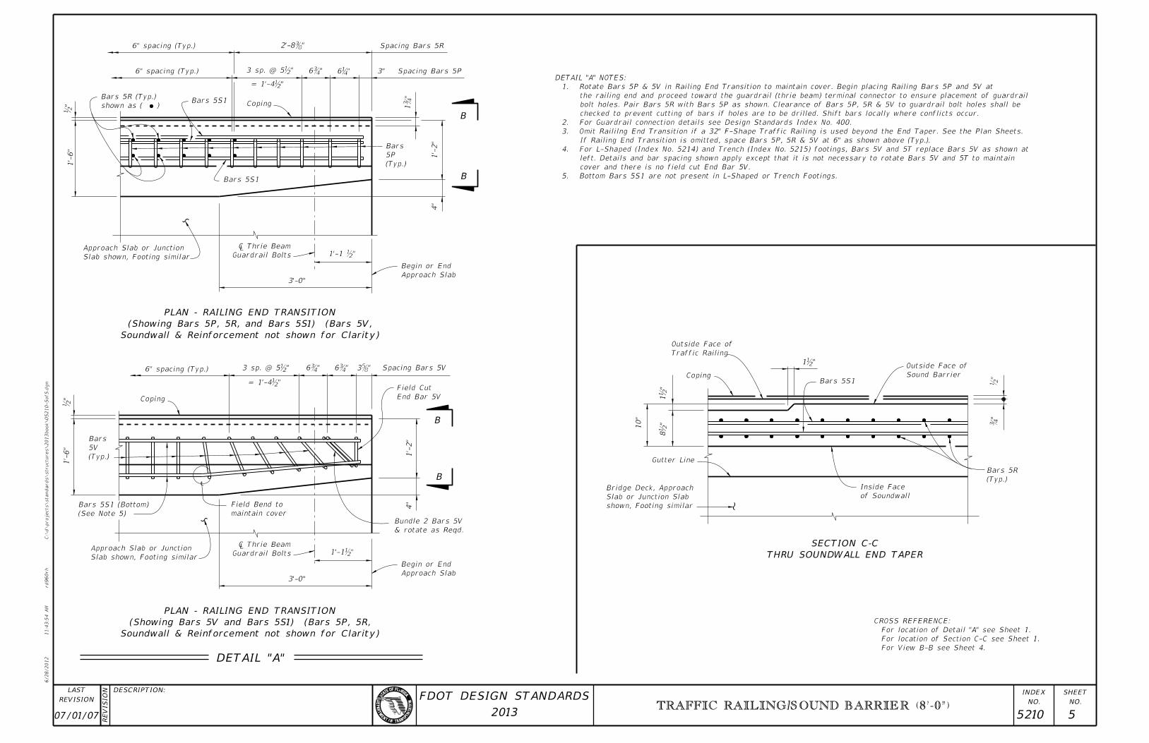
For View B-B see Sheet 4.
For location of Section C-C see Sheet 1.
For location of Detail "A" see Sheet 1.
CROSS REFERENCE:
of Soundwall
Inside Face
(Typ.)
Bars 5R
Sound Barrier
Outside Face of
Bars 5S1
Traffic Railing
Outside Face of
Coping
10"
Gutter Line
shown, Footing similar
Slab or Junction Slab
Bridge Deck, Approach
"�
"b
"b1
"b
1"
b8
5. Bottom Bars 5S1 are not present in L-Shaped or Trench Footings.
cover and there is no field cut End Bar 5V.
left. Details and bar spacing shown apply except that it is not necessary to rotate Bars 5V and 5T to maintain
4. For L-Shaped (Index No. 5214) and Trench (Index No. 5215) footings, Bars 5V and 5T replace Bars 5V as shown at
If Railing End Transition is omitted, space Bars 5P, 5R & 5V at 6" as shown above (Typ.).
3. Omit Raililng End Transition if a 32" F-Shape Traffic Railing is used beyond the End Taper. See the Plan Sheets.
2. For Guardrail connection details see Design Standards Index No. 400.
checked to prevent cutting of bars if holes are to be drilled. Shift bars locally where conflicts occur.
bolt holes. Pair Bars 5R with Bars 5P as shown. Clearance of Bars 5P, 5R & 5V to guardrail bolt holes shall be
the railing end and proceed toward the guardrail (thrie beam) terminal connector to ensure placement of guardrail
1. Rotate Bars 5P & 5V in Railing End Transition to maintain cover. Begin placing Railing Bars 5P and 5V at
DETAIL "A" NOTES:
6" spacing (Typ.)
6" spacing (Typ.) Spacing Bars 5P3"
Spacing Bars 5R
1’-
2"
(Typ.)
5P
Bars
4"
CopingBars 5S1
shown as ( )
Bars 5R (Typ.)
Bars 5S1
1’-
6"
Slab shown, Footing similar
Approach Slab or Junction
3’-0"Approach Slab
Begin or End
Guardrail Bolts
 � Thrie
"b1’-1
"�
1
"�6"�6
"b= 1’-4
" b3 sp. @ 5
"�2’-8
"b
6" spacing (Typ.) Spacing Bars 5V
End Bar 5V
Field Cut
1’-
2"
4"
Approach Slab
Begin or End
3’-0"
maintain cover
Field Bend to
Slab shown, Footing similar
Approach Slab or Junction
(See Note 5)
Bars 5S1 (Bottom)
(Typ.)
5V
Bars
1’-
6"
Coping
" b3 sp. @ 5
"b= 1’-4
"�6 "�6 "�3
1’-1b"Guardrail Bolts
 � Thrie
"b
DETAIL "A"
Soundwall & Reinforcement not shown for Clarity)
(Showing Bars 5V and Bars 5S1) (Bars 5P, 5R,
PLAN - RAILING END TRANSITION
B
B
Soundwall & Reinforcement not shown for Clarity)
(Showing Bars 5P, 5R, and Bars 5S1) (Bars 5V,
PLAN - RAILING END TRANSITION
B
B
THRU SOUNDWALL END TAPER
SECTION C-C
& rotate as Reqd.
Bundle 2 Bars 5V
07/01/07 5210 5
TRAFFIC RAILING/SOUND BARRIER (8’-0")