wall mount solo plus service manual 2001 to 2009 manuals/solo plus wall... · no x dia x len foster...
TRANSCRIPT

SOLO PLUS
WALL MOUNTED UNITS
2001 to 2009
ISO 14001 ISO 9001

1
SOLO PLUS UNITS 2003 Contents Page Introduction 1 Model Table 1 Environmental Management Policy 2 Disposal Requirements 2 Wall Mounted Units Dimensions 3 Location & Installation 3 to 4 Wall Mount Solo Units Power Absorption Table 4 Wall Mount Units Technical Data 5 Access to the Unit Compartment and Evaporator Housing 6 Controller Operation 6 to 7
Controller Parameters Access and Description for Models with Serial Number Ending in A, B, C, D and E 7 to 9
Parameter List for Models with Serial Number Ending in A, B and E 10 Controller Alarms and Alarm Descriptions for models with Serial Number End Letter from "A" TO "E" 11
Probe Resistance Values for all Models 11 Fuse Ratings and Wiring Diagram Numbers for Models with Serial Number Ending in A, B and E 11 Wiring Diagram Code Identifications 12 Controller Connections for Controller Kit Part Number 16250204 12 Wiring Diagrams for Models with Serial Number Ending in A, B and E 13 to 18
Parameter Access Instructions for Models with Serial Number Ending in F 19 Parameter List for Models with Serial Number Ending in F 20 Wiring Diagrams for Models with Serial Number Ending in F 21 to 26 Introduction
It is important to note that all work should be carried out by a competent person. Solo plus is a range of self contained refrigeration units for small and large coldrooms. The systems are pre-charged with refrigerant and pre-wired ready for installation into a coldroom with only electrical connections to be made. Under certain conditions a drain pipe may be required to drain any excess defrost water to an external source
Basic Description of Operation Hot gas defrost with crankcase protection Capillary control Hot gas vaporisation plus 2 additional electric back up heaters with variable voltage depending on water contact.
Routine Maintenance In order to keep the unit operating reliably and energy efficient periodical cleaning of the condenser is necessary. (The frequency being determined by site conditions) This operation is to be carried out with the unit turned OFF. We advise the use of an air jet blowing from inside to the outside. If an air jet is not available then use a soft long haired brush on the outside of the condenser taking care not to damage the fins. Warning: Condenser fins have sharp edges so care must be taken to avoid injury
Model Table Unit Type Refrigerator Meat Freezer
Temp + 10°C +1°C to +4°C 0°C to –2°C -18°C to -21°C Model
SP101HW SP201HW SP301HW SP401HW SP501HW SP601HW
SP101HW SP201HW SP301HW SP401HW SP501HW SP601HW
SP101HW SP201HW SP301HW SP401HW SP501HW SP601HW
SP101LW SP201LW SP301LW
NOTE: Nomenclature “W” refers to Wall Model As each model operates at different temperatures it will be necessary to set the required operating temperature. See controller instructions on pages 7 to 9 for models with serial number ending in A, B and E and 19 for models with serial number ending in F. See the parameter lists on page 10 for models with serial number ending in A, B and E and page 20 for models with serial number ending in F.

2
For Foster spare parts information and prices go to www.fosterrefigerator.co.uk. Once you have accessed the home page select ‘Spares’ from the menu on the left hand side of the page. The screen will change to the ‘Welcome to Foster WebSpares’ page. Click on ‘Browse Product’ and from there and select the product range you require followed by the model. From there select the part you require from the list or use the mouse pointer to highlight the part from the drawing, click the left mouse button for the part number, description and price to be displayed on the right hand side of the screen. For service manuals click on Service Documentation and select from the list.
.Environmental Management Policy.
Product Support and Installation Contractors
Foster Refrigerator recognises that its activities, products and services can have an adverse impact upon the environment. The organisation is committed to implementing systems and controls to manage, reduce and eliminate its adverse environmental impacts wherever possible, and has formulated an Environmental Policy outlining our core aims. A copy of the Environmental Policy is available to all contractors and suppliers upon request. The organisation is committed to working with suppliers and contractors where their activities have the potential to impact upon the environment. To achieve the aims stated in the Environmental Policy we require that all suppliers and contractors operate in compliance with the law and are committed to best practice in environmental management.
Product Support and Installation contractors are required to:
1. Ensure that wherever possible waste is removed from the client’s site, where arrangements are in place all waste should be returned to Foster Refrigerator’s premises. In certain circumstances waste may be disposed of on the client’s site; if permission is given, if the client has arrangements in place for the type of waste.
2. If arranging for the disposal of your waste, handle, store and dispose of it in such a way as to prevent its escape into the environment, harm to human health, and to ensure the compliance with the environmental law. Guidance is available from the Environment Agency on how to comply with the waste management ‘duty of care’.
3. The following waste must be stored separately from other wastes, as they are hazardous to the environment: refrigerants, polyurethane foam, oils.
4. When arranging for disposal of waste, ensure a waste transfer note or consignment note is completed as appropriate. Ensure that all waste is correctly described on the waste note and include the appropriate six-digit code from the European Waste Catalogue. Your waste contractor or Foster can provide further information if necessary.
5. Ensure that all waste is removed by a registered waste carrier, a carrier in possession of a waste management licence, or a carrier holding an appropriate exemption. Ensure the person receiving the waste at its ultimate destination is in receipt of a waste management licence or valid exemption.
6. Handle and store refrigerants in such a way as to prevent their emission to atmosphere, and ensure they are disposed of safely and in accordance with environmental law.
7. Make arrangements to ensure all staff who handle refrigerants do so at a level of competence consistent with the City Guilds 2078 Handling Refrigerants qualification or equivalent qualification.
8. Ensure all liquid substances are securely stored to prevent leaks and spill, and are not disposed of to storm drains, foul drain, surface water to soil.
DISPOSAL REQUIREMENTS If not disposed of properly all refrigerators have components that can be harmful to the environment. All old refrigerators must be disposed of by appropriately registered and licensed waste contractors, and in accordance with national laws and regulations.
3
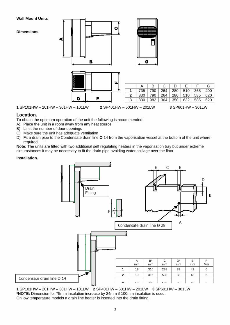
A B C D E F G 1 735 790 264 280 510 368 400 2 830 790 264 280 510 585 620 3 830 982 364 350 632 585 620
Wall Mount Units Dimensions 1 SP101HW – 201HW – 301HW – 101LW 2 SP401HW – 501HW – 201LW 3 SP601HW – 301LW
Location. To obtain the optimum operation of the unit the following is recommended: A) Place the unit in a room away from any heat source. B) Limit the number of door openings C) Make sure the unit has adequate ventilation D) Fit a drain pipe to the Condensate drain line Ø 14 from the vaporisation vessel at the bottom of the unit where
required Note: The units are fitted with two additional self regulating heaters in the vaporisation tray but under extreme circumstances it may be necessary to fit the drain pipe avoiding water spillage over the floor.
Installation.
1 SP101HW – 201HW – 301HW – 101LW 2 SP401HW – 501HW – 201LW 3 SP601HW – 301LW *NOTE: Dimension for 75mm insulation increase by 24mm if 100mm insulation is used. On low temperature models a drain line heater is inserted into the drain fitting.
A mm
B* mm
C mm
D* mm
E mm
F Mm
1 19 316 288 83 43 6
2 19 316 503 83 43 6
3 19 425 503 83 43 6
Drain Fitting

4
Wall Mount Solo Units Power Absorption Table
Compressor Unit Absorption Max Start Run Model Electrical
Supply Supplier Model Amp Amp Amp KW SP 101HW 230-1-50 Aspera E9213GK/CSR 5.9 17 4.9 0.9 SP 101HWLA 230-1-50 Aspera E9213GK/CSR 5.9 17 4.9 0.9 SP201 HW 230-1-50 Le Unite CAJ9480Z/F/CSR 9.1 26 5.5 1 SP201 HWLA 230-1-50 Le Unite CAJ9480Z/F/CSR 9.1 26 5.5 1 SP301HW 230-1-50 Le Unite CAJ9513Z/F/CSR 12.6 34 6.9 1.2 SP301HWLA 230-1-50 Le Unite CAJ9513Z/F/CSR 12.6 34 6.9 1.2 SP301HWLARP 230-1-50 Le Unite CAJ9513Z/F/CSR 12.6 34 6.9 1.2 SP401HW 230-1-50 Le Unite CAJ9513Z/F/CSR 13.8 36 8.1 1.4 SP401HWLN 230-1-50 Le Unite CAJ9513Z/F/CSR 13.8 36 8.1 1.4 SP401HWLA 230-1-50 Le Unite CAJ9513Z/F/CSR 13.8 36 8.1 1.4 SP501HW 400-3-50 Le Unite TAJ4519Z/T 7.9 28 6.6 2.1 SP501HWLA 400-3-50 Le Unite TAJ4519Z/T 7.9 28 6.6 2.1 SP501HWLARL 400-3-50 Le Unite TAJ4519Z/T 7.9 28 6.6 2.1 SP601HW 400-3-50 Maneurop MTZ28JE4 9.9 27 6.2 2.5 SP601HWNG 400-3-50 Maneurop MTZ28JE4 9.9 27 6.2 2.5 SP601HWLA 400-3-50 Maneurop MTZ28JE4 9.9 27 6.2 2.5 SP101LW 230-1-50 Le Unite CAJ2446Z/F/CSR 8.5 30 5.3 1 SP101LW 230-1-50 Le Unite CAJ2464Z/F/CSR 12.2 42 6.4 1.1 SP101LWLA 230-1-50 Le Unite CAJ2464Z/F/CSR 12.2 42 6.4 1.1 SP200LW 230-1-50 Le Unite CAJ2464Z/F/CSR 13 44 7.2 1.3 SP201LW 400-3-50 Le Unite TFH2480Z/T 7 28 5.4 1.7 SP201LWLA 400-3-50 Le Unite TFH2480Z/T 7 28 5.4 1.7 SP201LWPS 400-3-50 Le Unite TFH2480Z/T 7 28 5.4 1.7 SP201LWspe 230-1-50 Le Unite FH2480Z/F/CSR 22.3 73 8.8 1.5 SP301LW 400-3-50 Le Unite TFH2511Z/T 7.5 32 5.4 2 SP301LWLA 400-3-50 Le Unite TFH2511Z/T 7.5 32 5.4 2 SP301LWLARP 400-3-50 Le Unite TFH2511Z/T 7.5 32 5.4 2 SP301LWPS 400-3-50 Le Unite TFH2511Z/T 7.5 32 5.4 2
Door Opening
Door Opening
Door Opening

5
Wall MOUNT SOLO PLUS TECHNICAL DATA
STORAGE TEMP +10°C STORAGE TEMP +1/4°C STORAGE TEMP 0/-2°C STORAGE TEMP –18/-21°C Foster
Model No Ref Gas
Qty Grms
Capillary size No x Dia X Len
Foster Model No
Ref Gas
Qty Grms
Capillary size No x Dia X Len
Foster Model No
Ref Gas
Qty Grms
Capillary size No x Dia X
Len
Foster Model No
Ref Gas
Qty Grms
Capillary size No x Dia X
Len
SP 101HW R404A 0.67 1 x 1.5x 2500 SP 101HW R404A 0.67 1 x 1.5x 2500 SP 101HW R404A 0.67 1 x 1.5x 2500 SP 101LW R404A 0.53 1 x 1.5 x 2500
SP 201HW R404A 0.67 1 x 1.5 x 2500 SP 201HW R404A 0.67 1 x 1.5 x 2500 SP 201HW R404A 0.67 1 x 1.5 x 2500 SP 201LW R404A 0.84 1 x 1.8 x 2500
SP 301HW R404A 0.64 1 x 1.8 x 2000 SP 301HW R404A 0.64 1 x 1.8 x 2000 SP 301HW R404A 0.64 1 x 1.8 x 2000 SP 301LW R404A 1.13 2 x 1.6 x 2800
SP 401HW R404A 1.10 1 x 2.0 x 2900 SP 401HW R404A 1.10 1 x 2.0 x 2900 SP 401HW R404A 1.10 1 x 2.0 x 2900 SP 501HW R404A 0.88 2 x 1.8 x 2500 SP 501HW R404A 0.88 2 x 1.8 x 2500 SP 501HW R404A 0.88 2 x 1.8 x 2500 SP 601HW R404A 1.11 2 x 2.0 x 2000
SP 601HW R404A 1.11 2 x 2.0 x 2000
SP 601HW R404A 1.11 2 x 2.0 x 2000
STORAGE TEMP +10°C 32°C Ambient 43°C Ambient Air Air Vol Nominal
Foster Model No
Nom HP
HP Cut Out Press.
Bar
HP Cut In Press.
Bar
Suction Valve Press.
Bar
Noise Level dBa
Heat Rejected
Max Watts @ 32°C
Room Vent.
m³/ h # Watts Room Cap Watts Room
Cap Throw
mts m³/ h Volts Electrical
Phase Hz Amps Watts
Defrost Type
Condensate Vaporisation
Net. Wt. Kg
Gross Wt. Kg
SP 101HW 0.75 28 23 ------- 58 1900 700 1300 11 1160 8 4 600 230 1 50 3.9 600 Hot Gas Auto 53 74 SP 201HW 0.5 28 23 ------- 60 2050 700 1450 13 1200 11 4 600 230 1 50 5.5 600 Hot Gas Auto 56 77 SP 301HW 0.75 28 23 ------- 60 2700 700 1800 16 1550 14 4 600 230 1 50 5.6 900 Hot Gas Auto 64 85 SP 401HW 0.75 28 23 ------- 60 3650 1400 2550 25 2200 20 4 1200 230 1 50 7 1100 Hot Gas Auto 80 110 SP 501HW 1 28 23 ------- 62 5100 1400 3100 33 2700 27 4 1200 400 3 50 5.2 1800 Hot Gas Auto 80 110 SP 601HW 1.5 28 23 ------- 63 6900 1500 4700 58 4000 48 9.5 1800 400 3 50 5.9 2200 Hot Gas Auto 100 135
STORAGE TEMP +1/4°C 32°C Ambient 43°C Ambient Air Air Vol Nominal Foster
Model No Nom HP
HP Cut Out Press.
Bar
HP Cut In Press.
Bar
Suction Valve Press.
Bar
Noise Level dBa
Heat Rejected
Max Watts @ 32°C
Room Vent.
m³/ h # Watts Room Cap Watts Room
Cap Throw
mts m³/ h Volts Electrical
Phase Hz Amps Watts
Defrost Type
Condensate Vaporisation
Net. Wt. Kg
Gross Wt. Kg
SP 101HW 0.75 28 23 ------- 58 1650 700 1050 7 900 6 4 600 230 1 50 3.9 600 Hot Gas Auto 53 74 SP 201HW 0.5 28 23 ------- 60 1756 700 1150 9 1050 7 4 600 230 1 50 5.5 600 Hot Gas Auto 56 77 SP 301HW 0.75 28 23 ------- 60 2356 700 1450 13 1300 10 4 600 230 1 50 5.6 900 Hot Gas Auto 64 85 SP 401HW 0.75 28 23 ------- 60 3000 1400 1900 20 1600 14 4 1200 230 1 50 7 1100 Hot Gas Auto 80 110 SP 501HW 1 28 23 ------- 62 4500 1400 2700 30 2350 24 4 1200 400 3 50 5.2 1800 Hot Gas Auto 80 110 SP 601HW 1.5 28 23 ------- 63 6300 1500 4100 50 3300 35 9.5 1800 400 3 50 5.9 2200 Hot Gas Auto 100 135
STORAGE TEMP 0/-2°C 32°C Ambient 43°C Ambient Air Air Vol Nominal Foster
Model No Nom HP
HP Cut Out Press.
Bar
HP Cut In Press.
Bar
Suction Valve Press.
Bar
Noise Level dBa
Heat Rejected
Max Watts @ 32°C
Room Vent.
m³/ h # Watts Room Cap Watts Room
Cap Throw
mts Air Vol Volts Electrical
Phase Hz Amps Watts
Defrost Type
Condensate Vaporisation
Net. Wt. Kg
Gross Wt. Kg
SP 101HW 0.375 28 23 ------- 58 1450 700 850 6 750 5 4 600 230 1 50 3.9 600 Hot Gas Auto 53 74
SP 201HW 0.5 28 23 ------- 60 1550 700 950 7 850 6 4 600 230 1 50 5.5 600 Hot Gas Auto 56 77 SP 301HW 0.75 28 23 ------- 60 2100 700 1300 11 1200 9 4 600 230 1 50 5.6 900 Hot Gas Auto 64 85 SP 401HW 0.75 28 23 ------- 60 2800 1400 1700 15 1400 11 4 1200 230 1 50 7 1100 Hot Gas Auto 80 110 SP 501HW 1 28 23 ------- 62 4100 1400 2300 21 2000 17 4 1200 400 3 50 5.2 1800 Hot Gas Auto 80 110 SP 601HW 1.5 28 23 ------- 63 5550 1500 3350 36 2800 26 9.5 1800 400 3 50 5.9 2200 Hot Gas Auto 100 135
STORAGE TEMP –18/-21°C
32°C Ambient 43°C Ambient Air Air Vol Nominal Foster Model No
Nom HP
HP Cut Out Press.
Bar
HP Cut In Press.
Bar
Suction Valve Press.
Bar
Noise Level dBa
Heat Rejected
Max Watts @ 32°C
Room Vent.
m³/ h # Watts Room Cap Watts Room
Cap Throw
mts Air Vol Volts Electrical
Phase Hz Amps Watts
Defrost Type
Condensate Vaporisation
Net. Wt. Kg
Gross Wt. Kg
SP 101LW 1.25 28 23 2.5 62 1950 700 1050 7 850 5 4 600 230 1 50 5.2 900 Hot Gas Auto 64 85 SP 201LW 1.5 28 23 2.5 63 3200 1400 1700 14 1400 10 4 1200 400 3 50 4.3 1500 Hot Gas Auto 80 110 SP 301LW 2.2 28 23 2.5 63 4440 1500 2700 28 2250 20 9.5 1800 400 3 50 4.5 1700 Hot Gas Auto 105 140
NOTE: Noise levels taken in a room with a concrete floor, no sound attenuation and ceiling height of 7 metres with the unit base 1.5 metres from floor level, installed in a coldroom and the Sound Metre at 3 metres distance. NOTE: The condenser fan pressure thermostat fitted on Low Ambient units should be set at 17bar with a 1.5bar differential; this applies to high and low temperature models.

ACCESS TO THE UNIT COMPARTMENT AND EVAPORATOR HOUSING Wall Model
Front Panel: Grasp each side of the front panel and “pull forward” releasing it from the spring clips located down each edge, it may be necessary to separate the front panel from the main body using a flat blade screwdriver and gently ease away.
Condenser Fan Assembly
After removing the front panel “pull upwards” the condenser fan housing assembly to release it from the 4 “spring clips” located in each corner. It may be necessary to separate the fan housing assembly from the main body using a flat blade screwdriver and gently easing upwards.
Evaporator fan assembly
Remove the screw securing the drain tube to the drip tray and remove the drain tube Remove the four screws securing the drain pan and remove. Remove the three remaining screws securing the side panel and remove it allowing access into the evaporator fan assembly.
Controller Operation Description of electronic panel
2. Control LED (Green): ON: evaporator fan is running. Flashing: evaporator fan is in start mode. OFF: evaporator is off. Defrost in operation
1. Control LED (Green): LIT: Compressor running, Unit is refrigerating FLASHING: Compressor is in start delay mode (waiting for signal to start) OFF: Compressor is OFF. Room is down to temperature.
3. Control LED (Yellow): LIT: Unit in defrost mode (auto or manual) Flashing: Manual defrost mode in operation.
4. Alarm LED (Red): LIT: Alarm is active – see separate ALARMS section. OFF: Unit is functioning normally

7
Note: Prior to switching on the unit the following checks should be made. Connect the mains supply. All electrical connections are terminated correctly. All fixing screws are fully tightened. Having made the pre start checks switch on the unit: The display will illuminate and OFF appears on the display. It is important to note that the condenser fan will run continuously when there is power to the unit and the display is illuminated.
Room temperature settings. Set the required room temperature. Turn the unit ON using the ON/OFF key. Programming room temperature. To set the required room temperature press the SET key for more than 3 seconds. The Green LED will light and the previous set temperature will be displayed. To increase the set value press the UP key until the desired temperature is achieved. To lower the set value press the DOWN key until the desired temperature is achieved. On completion press the SET key or wait 5 seconds for the changes to be saved.
Controller Parameters Access Instruction for Models with Serial Number
Ending in A, B, C, D and E Turn the unit ON using the ON/OFF key.
Hold the ENTER key for at least 3 seconds (the green LED above SET (6) will illuminate) entry is permitted to the thr level menu. Use the UP key PL1 will be displayed. On reaching PL1 in the menu press the ENTER key PRC will be displayed.
5. Display: When connected to the mains the display will read OFF indicating the condition of the unit. By pressing the ON/OFF key for 5 seconds the unit will turn ON and display the room temperature. During programming mode the various parameters will be displayed and during alarm mode an alarm code will be displayed.
6. SET/ESC key: Pressed for 3 seconds, the led is lit and setting of required room temperature is enabled. During programming it is used to pass from a sub menu to an upper one.
7. DOWN/ ROOM LIGHT Key: During programming mode or setting of room temperature it serves to reduce the displayed value. At other times it serves to control the room light
8. DEFROST/ UP Key: By pressing for more than 4 seconds it activates a manual defrost. During programming mode or setting of room temperature it serves to increase the displayed value
9. ON/OFF Key: To turn the unit ON or OFF press and hold for more than 3 seconds.
10. ENTER Key: Permits access to the programming menu and passage to the sub menu. Access to this programming mode should be by qualified persons only.
8
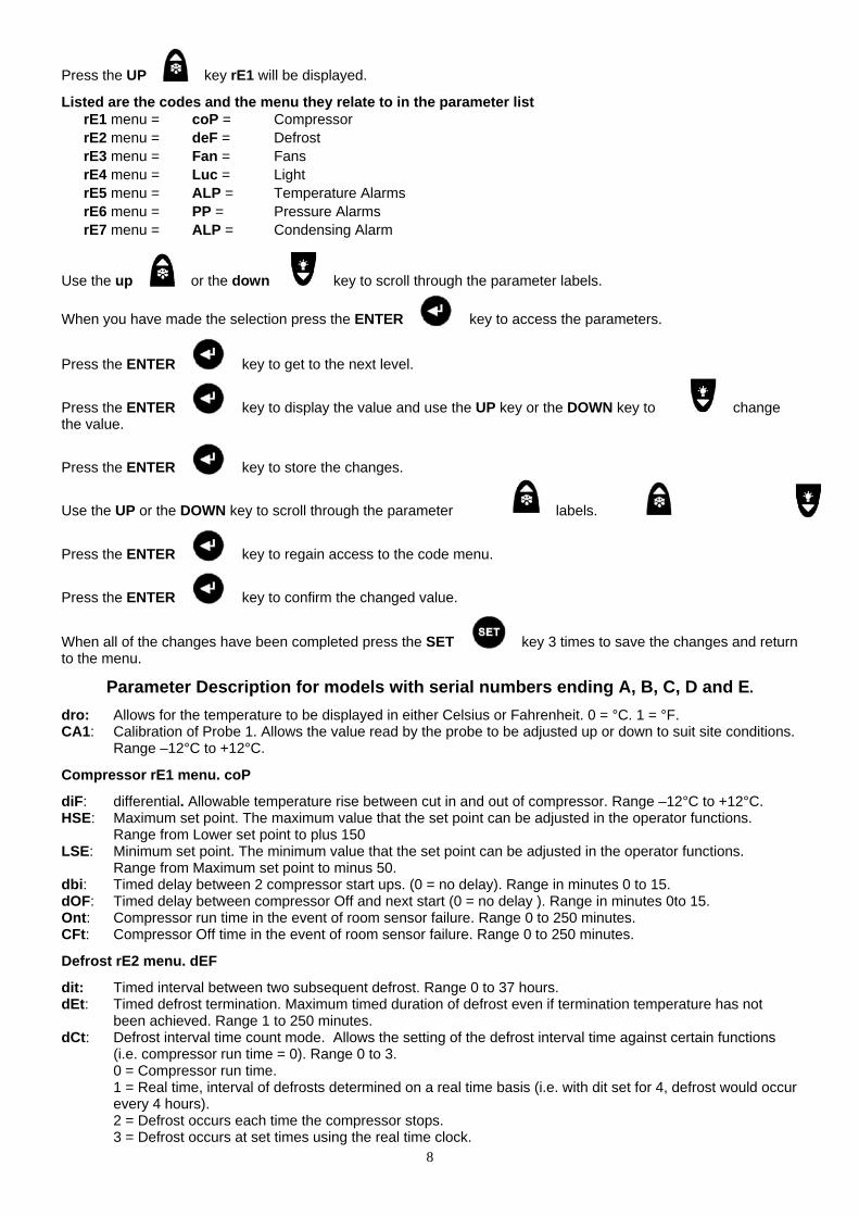
Press the UP key rE1 will be displayed.
Listed are the codes and the menu they relate to in the parameter list rE1 menu = coP = Compressor rE2 menu = deF = Defrost rE3 menu = Fan = Fans rE4 menu = Luc = Light rE5 menu = ALP = Temperature Alarms rE6 menu = PP = Pressure Alarms rE7 menu = ALP = Condensing Alarm
Use the up or the down key to scroll through the parameter labels. When you have made the selection press the ENTER key to access the parameters.
Press the ENTER key to get to the next level.
Press the ENTER key to display the value and use the UP key or the DOWN key to change the value.
Press the ENTER key to store the changes.
Use the UP or the DOWN key to scroll through the parameter labels.
Press the ENTER key to regain access to the code menu.
Press the ENTER key to confirm the changed value.
When all of the changes have been completed press the SET key 3 times to save the changes and return to the menu.
Parameter Description for models with serial numbers ending A, B, C, D and E.
dro: Allows for the temperature to be displayed in either Celsius or Fahrenheit. 0 = °C. 1 = °F. CA1: Calibration of Probe 1. Allows the value read by the probe to be adjusted up or down to suit site conditions.
Range –12°C to +12°C.
Compressor rE1 menu. coP
diF: differential. Allowable temperature rise between cut in and out of compressor. Range –12°C to +12°C. HSE: Maximum set point. The maximum value that the set point can be adjusted in the operator functions.
Range from Lower set point to plus 150 LSE: Minimum set point. The minimum value that the set point can be adjusted in the operator functions.
Range from Maximum set point to minus 50. dbi: Timed delay between 2 compressor start ups. (0 = no delay). Range in minutes 0 to 15. dOF: Timed delay between compressor Off and next start (0 = no delay ). Range in minutes 0to 15. Ont: Compressor run time in the event of room sensor failure. Range 0 to 250 minutes. CFt: Compressor Off time in the event of room sensor failure. Range 0 to 250 minutes.
Defrost rE2 menu. dEF
dit: Timed interval between two subsequent defrost. Range 0 to 37 hours. dEt: Timed defrost termination. Maximum timed duration of defrost even if termination temperature has not
been achieved. Range 1 to 250 minutes. dCt: Defrost interval time count mode. Allows the setting of the defrost interval time against certain functions
(i.e. compressor run time = 0). Range 0 to 3. 0 = Compressor run time. 1 = Real time, interval of defrosts determined on a real time basis (i.e. with dit set for 4, defrost would occur every 4 hours). 2 = Defrost occurs each time the compressor stops. 3 = Defrost occurs at set times using the real time clock.

9
dtY Defrost type selection (timed , electric, hot gas off cycle). Range 0 to 3. 0 = Timed defrost. 1 = Electric defrost. 2 = Hot gas defrost. 3 = Off cycle.
dt: Drain down time. After the defrost has been completed the compressor and evaporator fan stay off for the duration of the fan delay period. Range 0 to 250 minutes.
dSt: Defrost termination temperature. The temperature at which the defrost relay is de-energised. Range -50°C to +150°C
Fans rE3 menu. FAn
Fdt: Fan delay time. Time in minutes to delay the evaporator start after a defrost. Range 0 to 15 minutes. FCO: Evaporator fan/s runs continuously. Allows selection of the fans to cycle with the compressor or to run
continuously. Range Y for fan/s to run continuously or N for fan/s to cycle with the compressor. dFd: fan/s stops during defrost. Allows for the option of the fan/s to run during defrost or to stop during defrost.
Range N to run during defrost or Y to stop during defrost. Fod: Fan/s OFF when door opened. Allows selection of the fan/s to run or not when the door is opened.
Range on for fan/s to run during door openings, no for fan/s to stop during door openings. Fst: Fan/s stop temperature. Allows the setting of the temperature that fan/s will be stopped at. The fan/s will
remain off as long as the value read by the defrost probe (placed on the evaporator) is higher than the set temperature value.
Room Light rE4 menu. LUc No parameters.
Temperature Alarms rE5 menu. ALP
LAL: Low temperature alarm. In the event of the air temperature dropping below the low temperature set point the alarm will sound and the alarm relay will be energised. The alarm set point is the value from the air temperature set point. Warning: the LAL parameter must be set to a negative value. Range HAL -50°C
HAL: High temperature alarm. In the event of the air temperature going higher than the high temperature set point the alarm will sound and the alarm relay will be energised. The alarm set point is the value from the air temperature set point.
AFd: alarm differential. Range -12°C to +12°C. PAO: Alarm delay after start up. Temperature alarms are overridden, in hours, when the unit is switched on. Range 0 to 10 hours.
dAo: Alarm delay after defrost. Temperature alarms are overridden, in minutes, after defrost. Range 0 to 250 minutes.
OAO: Alarm delay after opening. Temperature alarms are overridden, in hours, after door closure. Range 0 to 10 hours.
Pressure Alarms rE6 menu. PP
PEI: Time period for pressure trips. Time interval during which the number of times the high pressure trip is activated for an alarm condition to occur and the subsequent stopping of the compressor. Range 1 to 99 minutes.
Pen: Number of high-pressure trips. Number of high-pressure trips during the time as set in PEI for an alarm condition to be activated with the subsequent stopping of the compressor. Range 0 to 15.
Condensing Temperature Alarms rE7 menu. ALP
AL: Maximum condensing temperature alarm setpoint. In the event of the Condenser temperature going higher than the condenser temperature set point the alarm will sound and the alarm relay will be energised. Range 0°C to 99°C.
Afd: Alarm Differential. Allowable temperature rise between alarm activation and de-activation. Range -12°C to +12°C
Controller Part Numbers for Models with Serial Number Ending in ‘A’ ‘B’ and ‘E’.
Front Display PCB for all models 15344010 Controller PCB Kit for all Models 16250206
10
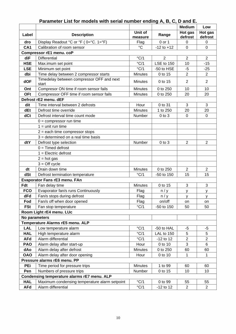
Parameter List for models with serial number ending A, B, C, D and E. Medium Low
Label Description Unit of measure Range Hot gas
defrost Hot gas defrost
dro Display Readout °C or °F ( 0=°C. 1=°F) Flag 0 or 1 0 0 CA1 Calibration of room sensor °C -12 to +12 0 0
Compressor rE1 menu. coP diF Differential °C/1 2 2 2
HSE Max.imum set point °C/1 LSE to 150 10 -15 LSE Minimum set point °C/1 -50 to HSE -5 -25 dbi Time delay between 2 compressor starts Minutes 0 to 15 2 2
dOF Timedelay between compressor OFF and next start Minutes 0 to 15 2 2
Ont Compresor ON time if room sensor fails Minutes 0 to 250 10 10 OFt Compressor OFF time if room sensor fails Minutes 0 to 250 20 20
Defrost rE2 menu. dEF dit Time interval between 2 defrosts Hour 0 to 31 3 3 dEt Defrost time override Minutes 1 to 250 20 20 dCt Defrost interval time count mode Number 0 to 3 0 0
0 = compressor run time 1 = unit run time 2 = each time compressor stops 3 = determined on a real time basis
dtY Defrost type selection Number 0 to 3 2 2 0 = Timed defrost 1 = Electric defrost 2 = hot gas 3 = Off cycle
dt Drain down time Minutes 0 to 250 2 2 dSt Defrost termination temperature °C/1 -50 to 150 15 15
Evaporator Fans rE3 menu. FAn Fdt Fan delay time Minutes 0 to 15 3 3 FCO Evaporator fan/s runs Continuously Flag n / y y y dFd Fan/s stops during defrost Flag n / y y y Fod Fan/s off when door opened Flag on/off on on FSt Fan stop temperature °C/1 -50 to 150 50 50
Room Light rE4 menu. LUc No parameters Temperature Alarms rE5 menu. ALP
LAL Low temperature alarm °C/1 -50 to HAL -5 -5 HAL High temperature alarm °C/1 LAL to 150 5 5 AFd Alarm differential °C/1 -12 to 12 2 2 PAO Alarm delay after start-up Hour 0 to 10 3 6 dAo Alarm delay after defrost Minutes 0 to 250 60 60 OAO Alarm delay after door opening Hour 0 to 10 1 1
Pressure alarms rE6 menu. PP PEi Time period for pressure trips Minutes 1 to 99 60 60 Pen Numbers of pressure trips Number 0 to 15 10 10
Condensing temperature alarms rE7 menu. ALP HAL Maximum condensing temperature alarm setpoint °C/1 0 to 99 55 55 AFd Alarm differential °C/1 -12 to 12 2 2
11
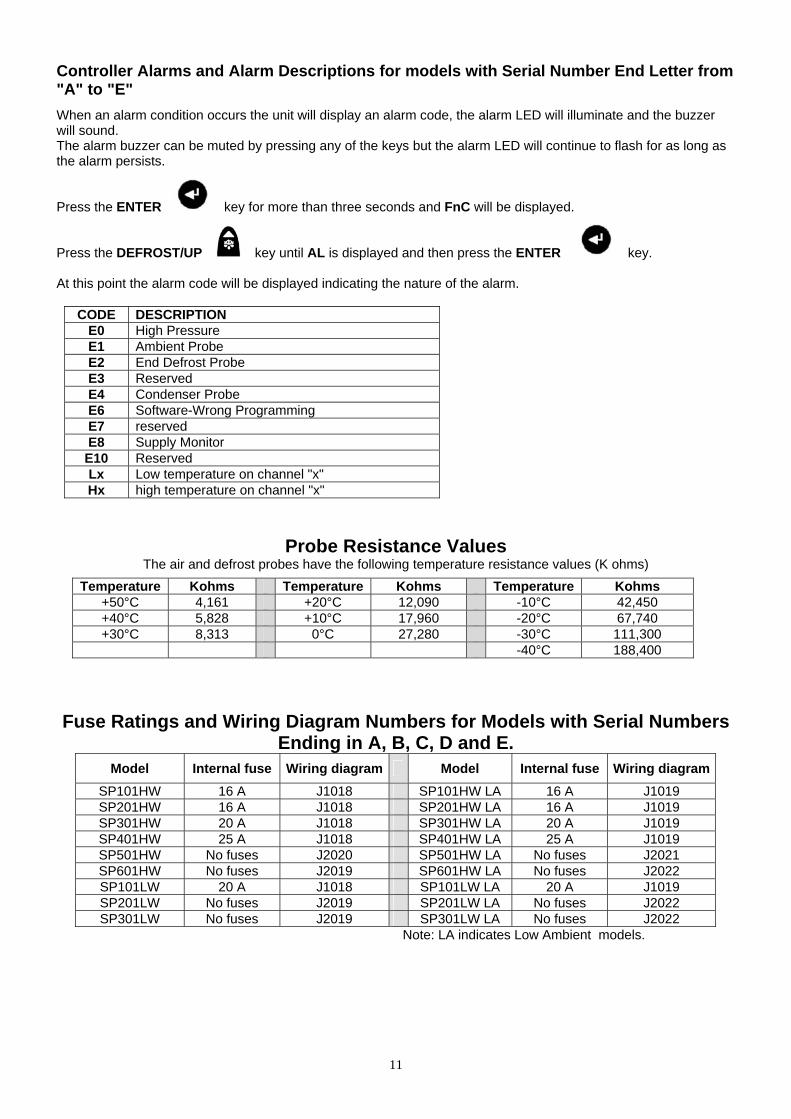
Controller Alarms and Alarm Descriptions for models with Serial Number End Letter from "A" to "E"
When an alarm condition occurs the unit will display an alarm code, the alarm LED will illuminate and the buzzer will sound. The alarm buzzer can be muted by pressing any of the keys but the alarm LED will continue to flash for as long as the alarm persists. Press the ENTER key for more than three seconds and FnC will be displayed. Press the DEFROST/UP key until AL is displayed and then press the ENTER key. At this point the alarm code will be displayed indicating the nature of the alarm.
CODE DESCRIPTION E0 High Pressure E1 Ambient Probe E2 End Defrost Probe E3 Reserved E4 Condenser Probe E6 Software-Wrong Programming E7 reserved E8 Supply Monitor
E10 Reserved Lx Low temperature on channel "x" Hx high temperature on channel "x"
Probe Resistance Values The air and defrost probes have the following temperature resistance values (K ohms)
Temperature Kohms Temperature Kohms Temperature Kohms +50°C 4,161 +20°C 12,090 -10°C 42,450 +40°C 5,828 +10°C 17,960 -20°C 67,740 +30°C 8,313 0°C 27,280 -30°C 111,300
-40°C 188,400
Fuse Ratings and Wiring Diagram Numbers for Models with Serial Numbers Ending in A, B, C, D and E.
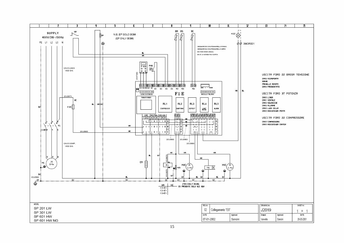
Model Internal fuse Wiring diagram Model Internal fuse Wiring diagramSP101HW 16 A J1018 SP101HW LA 16 A J1019 SP201HW 16 A J1018 SP201HW LA 16 A J1019 SP301HW 20 A J1018 SP301HW LA 20 A J1019 SP401HW 25 A J1018 SP401HW LA 25 A J1019 SP501HW No fuses J2020 SP501HW LA No fuses J2021 SP601HW No fuses J2019 SP601HW LA No fuses J2022 SP101LW 20 A J1018 SP101LW LA 20 A J1019 SP201LW No fuses J2019 SP201LW LA No fuses J2022 SP301LW No fuses J2019 SP301LW LA No fuses J2022
Note: LA indicates Low Ambient models.

12
Wiring Diagram Code Identifications
BA Room Sensor FTE Emergency ‘Stat BC Condenser Alarm Sensor HI Alarm BS Defrost Sensor K1 Contactor BVR Speed Regulator K11 Defrost Contactor BVRS Speed Regulator Sensor M1 Compressor Motor Nr.1 E Defrost Heater MPC Door Microswitch (Room) E1 Resistenza Carter Compressore MVC Condenser Fan Motor M1 Compressor Crankcase Heater MVE Evaporator Fan Motor EP Door Heater Circuit P1MX Cond. Fan Starting Pressure Switch ER1 Control Board Heater PMI L/P Switch ER2 Voltage Regulator Heater PMX H/P Switch ES Condensate Drain Heater Q1 Main Switch F13 Voltage Regulator Fuse Q3 Cond. Fan Speed Regulator “Off” Switch F1 Compressor Fuse T Transformer F1E Electronic Control Cab X Terminal Board-Connector F20 Auxiliary Fuse YG Refrigerant Solenoid FL Room Light Fuse YS Hot Gas Solenoid FM Voltage Regulator
Controller Connections for Controller Kit Part Number 16250206
Main PCB Main PCB Front Display Connections
SIGNAL Ground 12 Volt
Ground12 Volt Signal
Front Display Connections

13
Wiring Diagrams for Models with Serial Numbers Ending in A, B or E

14
15

16

17

18

19
Parameter Modification Instruction for Models with Serial Number Ending in ‘F’, ‘G’ and ‘H’.
Turn the unit ON using the ON/OFF key. Press and hold the ENTER key for five seconds. CP (Compressor Parameters) will be displayed Listed below are the codes and the menu they relate to in the parameter list
CP = Compressor Parameters dEF = Defrost Parameters FAn = Fan Parameters AL = Alarm Parameters PrE = Pressure Switch Input Parameters DiS = Display Parameters CnF = Configuration Parameters
Press the ENTER key to move to the first parameter Use the UP or DOWN key to scroll through the parameter list Select the required parameter and press the ENTER key to display the value. Use the UP or DOWN key to modify the value. Press the ENTER key to store the change When the required changes have been made press the SET key to move to the next sub folder. Continue using the same instruction and complete all of the required changes. Once all of the changes have been completed press the SET key twice or wait for ten seconds to return to the temperature display screen. Alarm Descriptions with Serial Number End Letter ending in ‘F’, ‘G’ and ‘H’.
CODE DESCRIPTION E1 Ambient Probe E2 End Defrost Probe E3 Condenser Probe E7 Bad Cominication To Keyboard EA SUPPLY MONITOR
AHx HIGH TEMPERATURE ON CHANNEL "x" Opd DOOR OPEN LPA LOW PRESSURE PRESSOSTAT HPA HIGH PRESSURE PRESSOSTAT
Controller Part Numbers for Models with Serial Number Ending in ‘F’, ‘G’ and ‘H’. Front Display PCB for all models 15344138 Controller PCB for all Models 15344131
Parameter List

20
Label Description DIM Medium Temp Settings
Low Temp Settings
CP Compressor Parameters dIF Differential °C/1 2 2
HSE Maximum allowed set point °C/1 10 -15 LSE Minimum allowed set point °C/1 -5 -25 Ont Compressor ON time if room sensor fails min 10 10 OFt Compressor OFF time if room sensor fails min 20 20 dOF Time between Compressor OFF and next start min 2 2 dbi Time between 2 compressor starts min 2 2 dEF Defrost Parameters dtY Defrost type: 1= Hot Gas. 0 = Electric num 1 1 Dit Time interval between 2 defrosts hours 3 3 dCt Defrost interval time count mode num 0 0 dEt Defrost time override min 20 20 dSt Defrost termination temperature °C/1 15 15 FAn Fan Parameters FSt Fan stop temperature °C/1 50 50 Fdt Fan delay time min 3 3 dt Drain down time min 2 2
dFd Fans OFF during defrost flag Y Y FCO Fans ON when compressor OFF flag Y Y FOd Fans OFF when door open flag n n AL Alarm Parameters AFd Alarm differential °C/1 2 2 HAL High temperature alarm set point °C/1 5 5 LAL Low temperature alarm set point °C/1 -5 -5 PAO Alarm delay after start up hours 3 6 dAo Alarm delay after defrost min 60 60 OAO Alarm delay after door opening hours 1 1 SA3 High temperature alarm set point °C/1 55 55 dA3 Differential °C/1 2 2 PrE Pressure Alarm Parameters PEn Number of pressure trips num 10 10 PEI Time period for pressure trips min 60 60 diS Display Parameters CA1 Room sensor calibration °C 0 0 drO Celsius or Fahrenheit temperature: 0 =°C. 1 = °F flag 0 0 CnF Configuration Parameters
Wiring Diagram Code Identifications BA Room Sensor FTE Emergency ‘Stat BC Condenser Alarm Sensor HI Alarm BS Defrost Sensor K1 Contactor BVR Speed Regulator K11 Defrost Contactor BVRS Speed Regulator Sensor M1 Compressor Motor Nr.1 E Defrost Heater MPC Door Microswitch (Room) E1 Resistenza Carter Compressore MVC Condenser Fan Motor M1 Compressor Crankcase Heater MVE Evaporator Fan Motor EP Door Heater Circuit P1MX Cond. Fan Starting Pressure Switch ER1 Control Board Heater PMI L/P Switch ER2 Voltage Regulator Heater PMX H/P Switch ES Condensate Drain Heater Q1 Main Switch F13 Voltage Regulator Fuse Q3 Cond. Fan Speed Regulator “Off” Switch F1 Compressor Fuse T Transformer F1E Electronic Control Cab X Terminal Board-Connector F20 Auxiliary Fuse YG Refrigerant Solenoid FL Room Light Fuse YS Hot Gas Solenoid FM Voltage Regulator
21
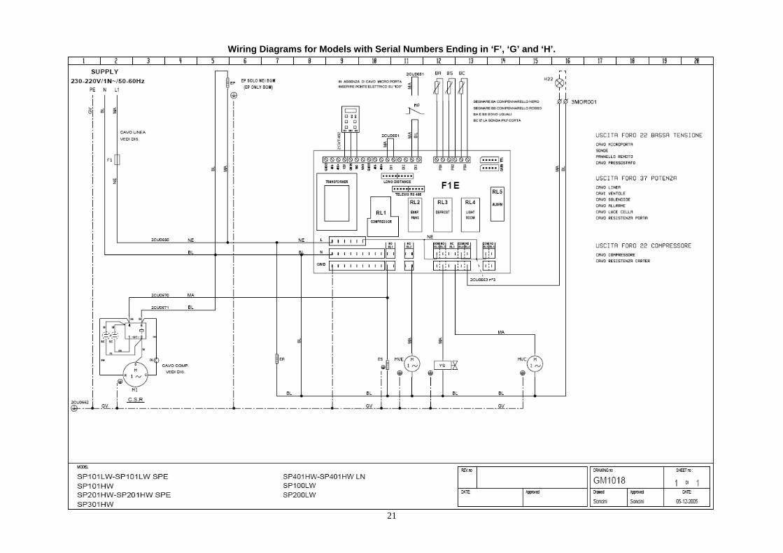
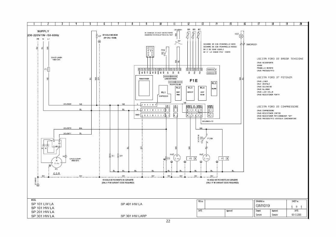
Wiring Diagrams for Models with Serial Numbers Ending in ‘F’, ‘G’ and ‘H’.
22

23

24

25

26

Foster European Operations France Foster Refrigerator France SA Tel: (33) 01 34 30 22 22. Fax: (33) 01 30 37 68 74. Email: [email protected] Germany Foster Refrigerator Gmbh, Tel: (49) 781 990 7840. Fax (49) 781 990 7844. Email: [email protected] Foster Refrigerator Oldmedow Road Kings Lynn Norfolk PE30 4JU Tel: 01553 691122 Fax: 01553 691447 Website: www.fosterrefrigerator.co.uk Email: [email protected] a Division of ‘ITW (UK) Ltd’ Wall Mount Solo/SM 06/09