waitaki dam 75 years on - engineering new zealand | … · 2009-11-04 · 1 3rd australasian...
TRANSCRIPT
1
3rd Australasian Engineering Heritage Conference 2009
Waitaki Dam – 75 Years On
Ian G Walsh – FIPENZ, MNZSOLD, MNZSEE, MNZGS, MNZSfRM
SUMMARY: The Waitaki Dam situated on the lower Waitaki River on the east coast of New Zealand’s South Island
was constructed between 1928 and 1934, a period influenced by the effects of the great depression. The overspill
concrete gravity structure is historically significant in several technical respects. This was the first hydro-electric
generation scheme developed on a major South Island waterway, and aspects of the design and construction presented
challenges that were new to New Zealand engineers. International design review during construction identified
shortcomings in the understanding of uplift pressures on the stability of the dam blocks, resulting in an additional
drainage gallery being retrofitted to the heel of the dam outside of the upstream face. Closure of the diversion sluices
presented a major difficulty as three gates overshot their seat and were unable to be raised back into position under the
pressure of the rising lake. An innovative sealing detail was developed, but the bitumen used at the time to grout the
final opening has been subject to extrusion over the years. Adequate stability of the dam blocks under uplift and
extreme loading including earthquake events has been an ongoing matter of investigation and analysis over the life of
the dam as engineering knowledge has progressed. In 1961 a major anchoring project was completed, where the dam
blocks were secured to the foundation by 300 ton capacity stressed and grouted cable anchors. Predicting the
reliability of the long term performance of these fully grouted anchors has presented difficulties, and further uplift
control improvements were completed in the early 1990’s to improve confidence in the performance of the dam.
1. GENERAL
The Waitaki Hydro Electric Power Station is located
on the Waitaki River in the South Island of New
Zealand, 6km upstream from the township of Kurow
(Figure 1).
Figure 1. Location
It is currently the last in a cascade of power stations
owned by Meridian Energy Ltd that utilise the 342
cumec mean flow of the Waitaki River that originates
from Lakes Tekapo, Pukaki, and Ohau and flows to the
East Coast between Dunedin and Christchurch.
This was the first hydro scheme developed on the river, and in fact the first constructed on a major river in the
South Island by the then Public Works Department.
This year (2009) will see the achievement of 75 years
of successful operation of the power station, and the
supply of valuable energy to the people of New
Zealand.
However, the success has not been without its
challenges and difficulties (Anderson 1937) as
engineering knowledge and experience regarding such
significant civil engineering undertakings has been
gained over the years (Ridley 1954). Design knowledge in New Zealand in the 1920’s and 1930’s
was not particularly advanced in this type of
development, and several non-conservative aspects of
the original design have lead to progressive
reassessment and modification to the dam from the
time of construction up to the present day
As a depression era project constructed with much
manual labour input over the period 1928 to 1934, the
dam has a special place in the social changes that
occurred at that time leading to the introduction of the social security system to protect workers against the
effects of unemployment (Natusch 1984).
This site has significant value in terms of our
engineering heritage, as it contains visible evidence of
our increasing ability to tackle major infrastructure
works in a time when manual labour was still a key
element in the construction process. In this paper I
have focussed on the civil engineering aspects with a

2
bias towards dam safety management, as this is my
particular area of activity.
2. DESCRIPTION
The dam site was originally referred to as “Awakino”
after the locality, but as the first “dam on the Waitaki
River”, the work came to be called simply the Waitaki
Dam, despite the official expectation of further future
development on the river. The site was chosen in 1927
for its topographic and geological setting. The ability
to construct the large powerhouse on the southern bank
(true right) clear of the main river channel, and the
presence of good foundation conditions in the form of
greywacke rock under a shallow cover of alluvial
gravel suitable for concrete production were key
factors in the selection. The existence of the Dryburgh fault in the vicinity was known, but seismic
considerations generally were not initially thought to
be significant in this area.
Figure 2. View of Site from the North Bank c2002
The major components of the current site comprise a
354m long 36.5m maximum height concrete gravity
dam, which also acts as an overflow spillway (Figure
2), together with a 105MW capacity powerhouse on the
south bank housing 7 machines utilising an operating
head of ≈21m. The curved layout of the overspill dam
was built to suit the discharge flow direction into the
river channel, and is not designed to act as an arch
dam. The radius of the curve is 609.6m on the true
right, and 228.6m on the true left, with straight sections
at the power house and abutments.
The 150m long reinforced concrete power house is an
impressive structure in its own right. The two
machines initially commissioned in 1934 are shown in
the background in Figure 3. The original power house
was constructed to accommodate five machines which
were progressively installed, and the power house was
extended into the right abutment in the period 1948 to
1954 to accommodate a further two machines.
Figure 3. View inside Power House c2003
Figure 4. Site Layout Plan

3
The 21 dam blocks are typically some 16m wide
forming an uncontrolled ogee type spillway to carry the
design flood from the 9735 km2 catchment.
The block joints are sealed with oxidised bitumen of
40/50 penetration grade placed after completion of the
concrete placing and curing in formed continuous
pockets at the contraction joints. Construction diversion was achieved through a series of eleven 3.7m
high by 3m wide temporary sluices on the northern end
of the dam adjacent to the true left abutment which
were subsequently infilled; not totally successfully in
all cases as is discussed later.
Galleries are present at three levels within the dam; the
uppermost air gallery which provides an air supply to
the aeration vents on the spillway face, the middle
gallery, and the lower Hornell gallery at foundation
level outside the heel of the dam. This latter feature is
unusual and has an interesting history that is discussed later. Internal drainage is by pumping from a central
pump shaft on the upstream face, although originally a
venturi piping system was installed. There is some
question as to the effectiveness with which this device
might ever have functioned, but it was never
commissioned to test the original design concept.
Original foundation drainage was provided by porous
“no-fines” concrete drains placed on the prepared rock
foundation, but subsequent stability considerations
resulted in relief drains being drilled during the 1950’s
and in the period 1960 to 1961 a series of 200 and 300 tonne capacity anchor cables was placed, grouted and
stressed in holes drilled from the dam crest into the
foundations. These cables were subsequently fully
grouted, preventing any further proof testing of their
condition.
The main features described are shown in Figure 5
below.
Figure 5. Typical Cross Section
The typical cross section shows the change in slope of
the dam face from 0.667H:1V to 0.80H:1V which
applied to later dam blocks after the non-conservative
nature of the original design was identified.
3. CONSTRUCTION METHOD
Construction of the power house situated on the south
bank of the river away from the main river channel was
able to be commenced early to give time for the
generation plant to be installed while the dam wall
progressed across the river channel in conditions
exposed to flood hazards. River diversion and
dewatering for construction were major considerations
for this project as the first development of its type in the South Island. Block 14 was designed as a
temporary pier constructed with sheet piling providing
a secure temporary abutment for the Canterbury (north
bank) and Otago (south bank) coffer dams. The
following images illustrate progressive nature of the
construction as diversion was achieved and
construction of the blocks completed.
Figure 6. Power House Foundation Construction and
Concrete Intakes and Penstocks c1930-31
Figure 7. First trestle bridge cDec 1928. Damaged by
a flood in Jan 1929
4
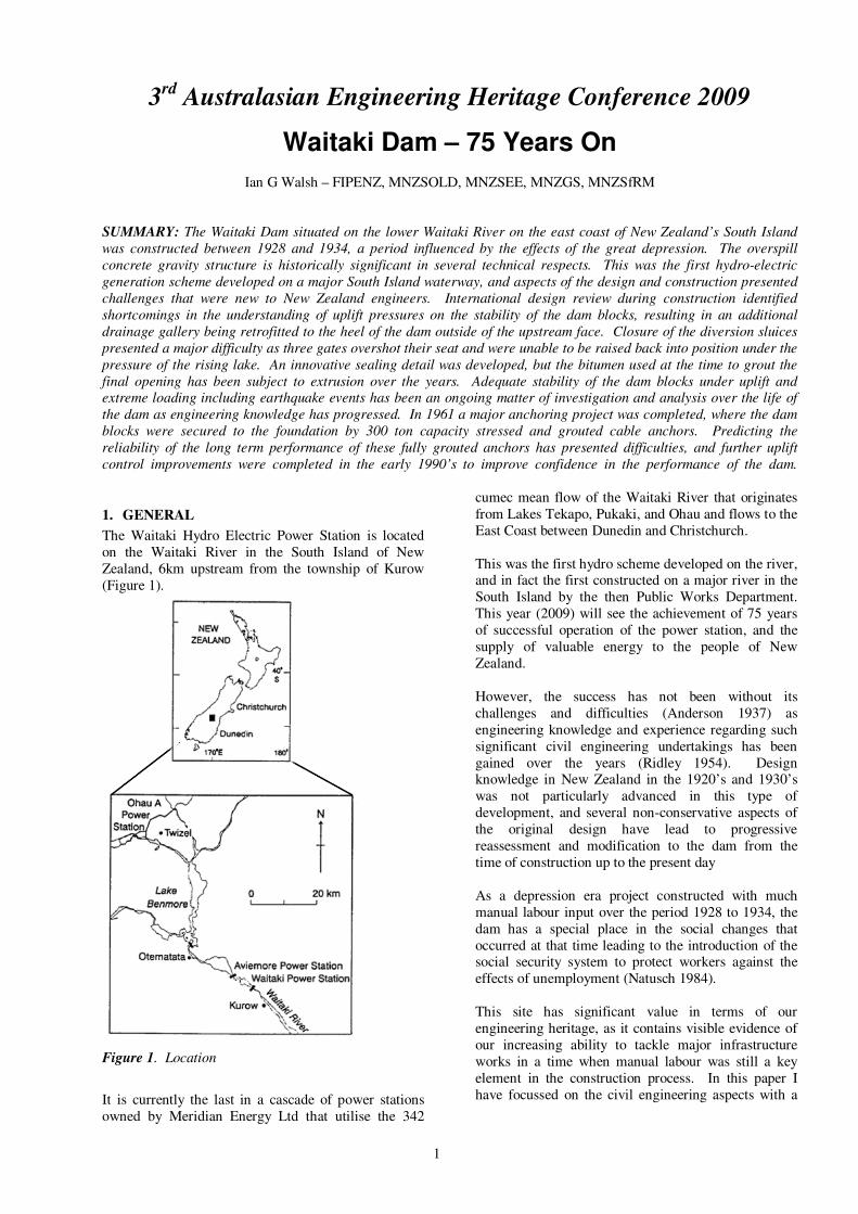
Figure 8. View of Block 14 Pier, Canterbury coffer dam sheet piling and earthworks constructed off the trestle bridge
c1930
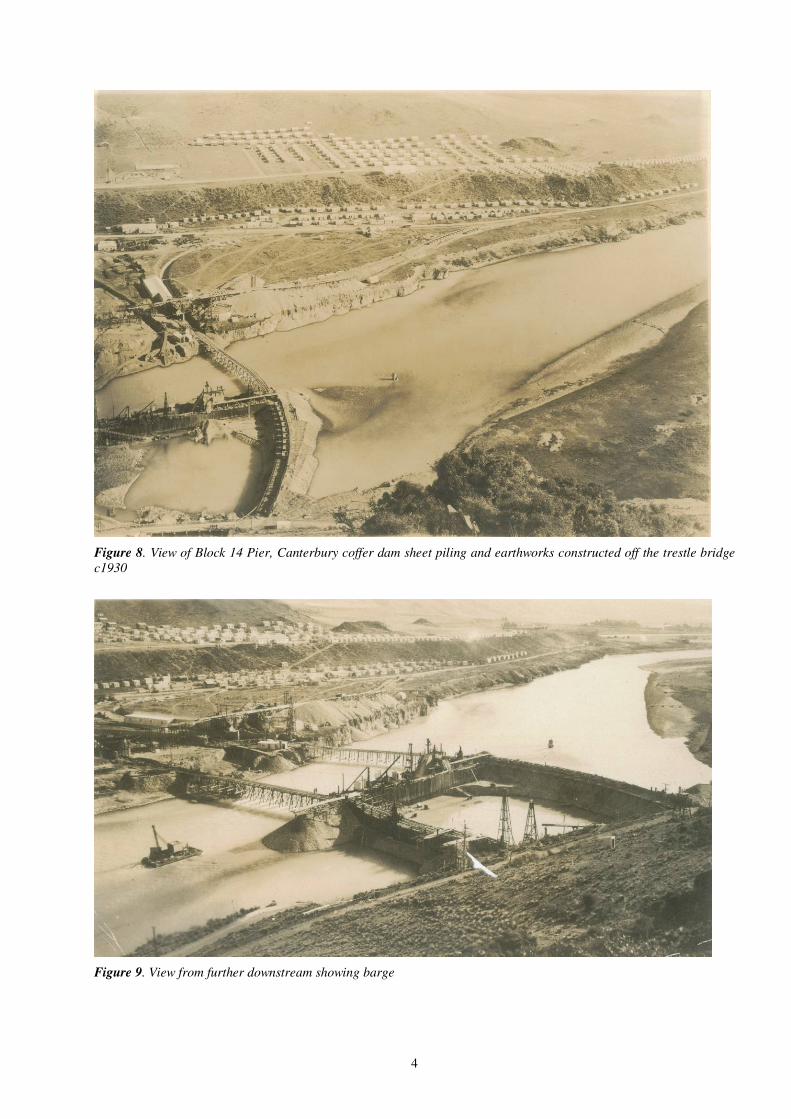
Figure 9. View from further downstream showing barge

5
Figure 10. Dewatered Canterbury foundations under proposed diversion sluice blocks

6
Figure 11. Diversion sluices well advanced. Aggregate recovery progressing. Power house falsework in background
Figure 12. View from Canterbury abutment; blocks progressing adjacent to diversion sluices
7
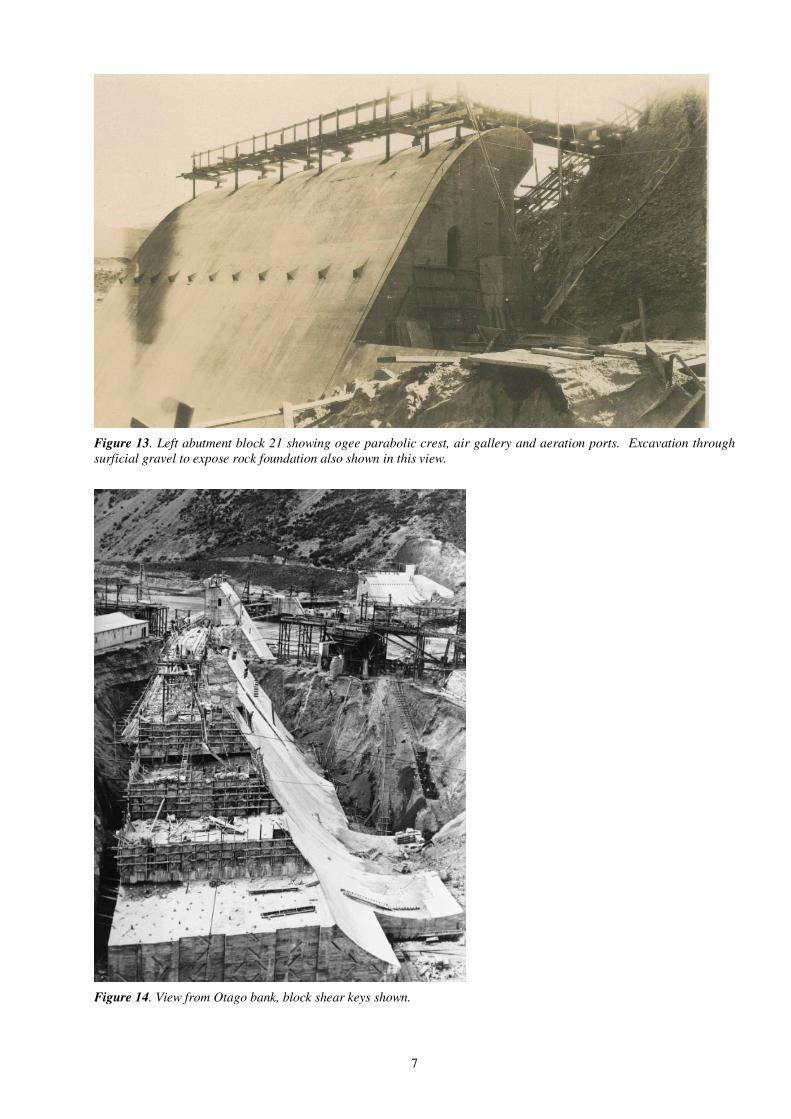
Figure 13. Left abutment block 21 showing ogee parabolic crest, air gallery and aeration ports. Excavation through
surficial gravel to expose rock foundation also shown in this view.
Figure 14. View from Otago bank, block shear keys shown.

8
Figure 15. View from Canterbury bank at similar stage
Figure 16. Canterbury abutment wing wall completed
9
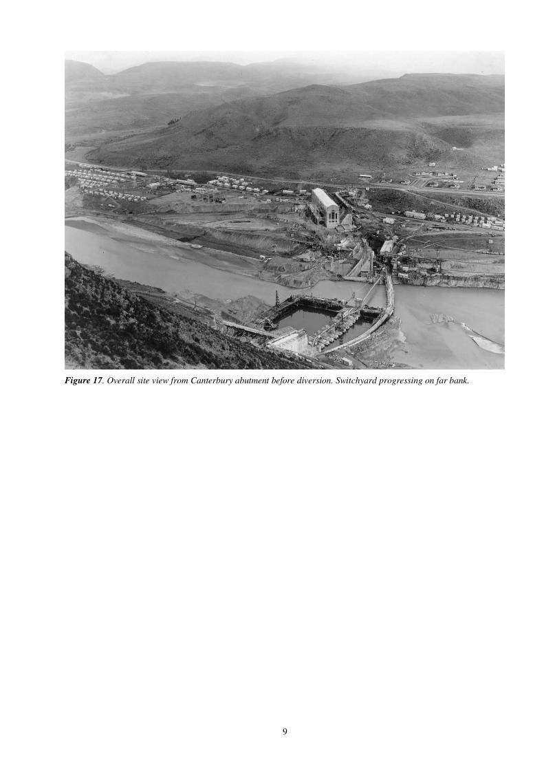
Figure 17. Overall site view from Canterbury abutment before diversion. Switchyard progressing on far bank.
10
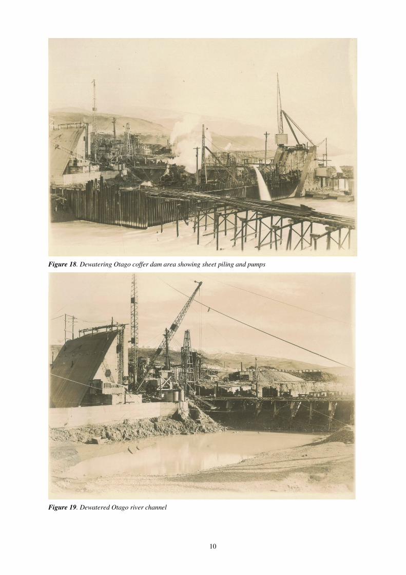
Figure 18. Dewatering Otago coffer dam area showing sheet piling and pumps
Figure 19. Dewatered Otago river channel
11
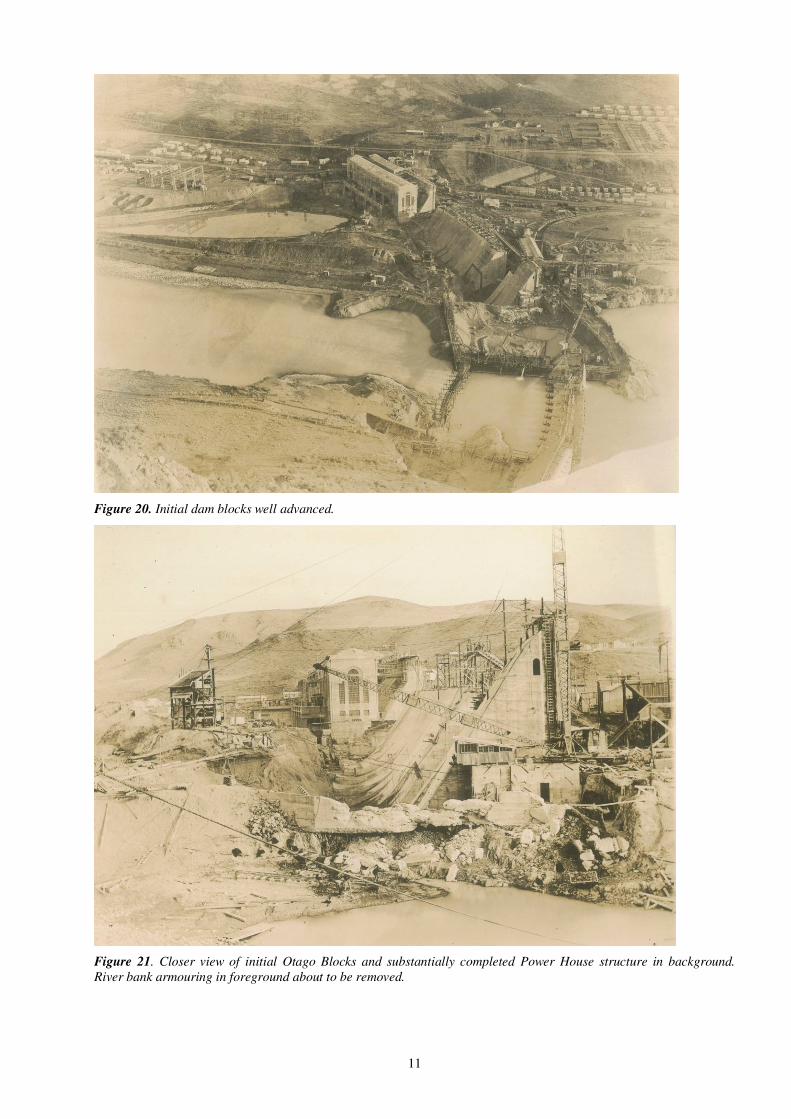
Figure 20. Initial dam blocks well advanced.
Figure 21. Closer view of initial Otago Blocks and substantially completed Power House structure in background.
River bank armouring in foreground about to be removed.
12
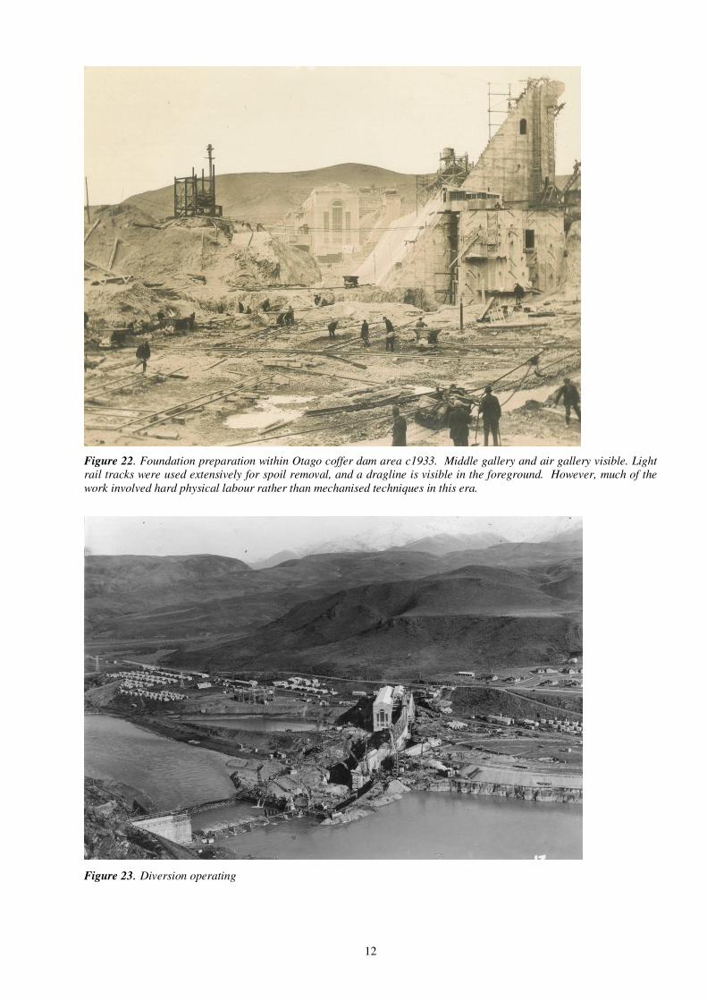
Figure 22. Foundation preparation within Otago coffer dam area c1933. Middle gallery and air gallery visible. Light
rail tracks were used extensively for spoil removal, and a dragline is visible in the foreground. However, much of the
work involved hard physical labour rather than mechanised techniques in this era.
Figure 23. Diversion operating

13
Figure 24. Completion of concreting over the diversion sluices and placing the bulkheads c 1934. The supports to the
last three bulkhead gates placed after this photo was taken structurally failed when being placed during high headpond
level, resulting in the bulkheads overshooting their seating and not sealing as intended. This situation did not stop the
filling of the lake nor the planned official opening.
Figure 25. Official opening 27 Oct 1934
The very large power house by today’s standards for a 75MW station was needed to accommodate the large diameter
machines that were designed to have very high rotational inertia to limit the risk of surge induced overspeed problems
related to the small capacity of the receiving grid in those days. The station operated for a short time on 1/3 power
output at 66kV rather than the intended 110kV until the remote grid transformers were upgraded.
The three leaking sluices still remained to be stopped,
so efforts were made to seal the bulkhead openings
with whatever could be sourced to plug the gap to
enable permanent concrete infill to be placed. These
14
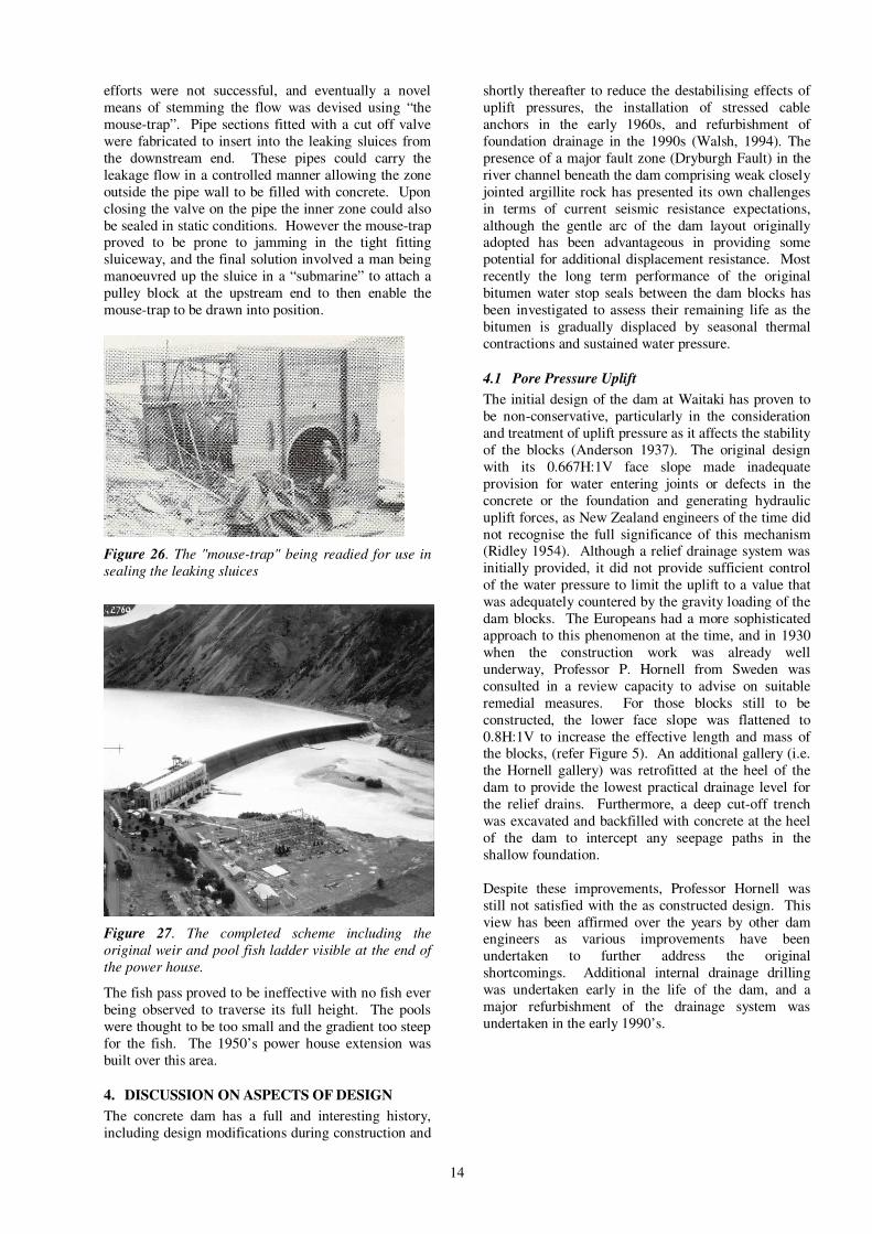
efforts were not successful, and eventually a novel
means of stemming the flow was devised using “the
mouse-trap”. Pipe sections fitted with a cut off valve
were fabricated to insert into the leaking sluices from
the downstream end. These pipes could carry the
leakage flow in a controlled manner allowing the zone
outside the pipe wall to be filled with concrete. Upon
closing the valve on the pipe the inner zone could also
be sealed in static conditions. However the mouse-trap proved to be prone to jamming in the tight fitting
sluiceway, and the final solution involved a man being
manoeuvred up the sluice in a “submarine” to attach a
pulley block at the upstream end to then enable the
mouse-trap to be drawn into position.
Figure 26. The "mouse-trap" being readied for use in
sealing the leaking sluices
Figure 27. The completed scheme including the
original weir and pool fish ladder visible at the end of
the power house.
The fish pass proved to be ineffective with no fish ever
being observed to traverse its full height. The pools
were thought to be too small and the gradient too steep
for the fish. The 1950’s power house extension was
built over this area.
4. DISCUSSION ON ASPECTS OF DESIGN
The concrete dam has a full and interesting history,
including design modifications during construction and
shortly thereafter to reduce the destabilising effects of
uplift pressures, the installation of stressed cable
anchors in the early 1960s, and refurbishment of
foundation drainage in the 1990s (Walsh, 1994). The
presence of a major fault zone (Dryburgh Fault) in the
river channel beneath the dam comprising weak closely
jointed argillite rock has presented its own challenges
in terms of current seismic resistance expectations,
although the gentle arc of the dam layout originally adopted has been advantageous in providing some
potential for additional displacement resistance. Most
recently the long term performance of the original
bitumen water stop seals between the dam blocks has
been investigated to assess their remaining life as the
bitumen is gradually displaced by seasonal thermal
contractions and sustained water pressure.
4.1 Pore Pressure Uplift
The initial design of the dam at Waitaki has proven to
be non-conservative, particularly in the consideration
and treatment of uplift pressure as it affects the stability
of the blocks (Anderson 1937). The original design
with its 0.667H:1V face slope made inadequate
provision for water entering joints or defects in the
concrete or the foundation and generating hydraulic
uplift forces, as New Zealand engineers of the time did
not recognise the full significance of this mechanism (Ridley 1954). Although a relief drainage system was
initially provided, it did not provide sufficient control
of the water pressure to limit the uplift to a value that
was adequately countered by the gravity loading of the
dam blocks. The Europeans had a more sophisticated
approach to this phenomenon at the time, and in 1930
when the construction work was already well
underway, Professor P. Hornell from Sweden was
consulted in a review capacity to advise on suitable
remedial measures. For those blocks still to be
constructed, the lower face slope was flattened to
0.8H:1V to increase the effective length and mass of the blocks, (refer Figure 5). An additional gallery (i.e.
the Hornell gallery) was retrofitted at the heel of the
dam to provide the lowest practical drainage level for
the relief drains. Furthermore, a deep cut-off trench
was excavated and backfilled with concrete at the heel
of the dam to intercept any seepage paths in the
shallow foundation.
Despite these improvements, Professor Hornell was
still not satisfied with the as constructed design. This
view has been affirmed over the years by other dam engineers as various improvements have been
undertaken to further address the original
shortcomings. Additional internal drainage drilling
was undertaken early in the life of the dam, and a
major refurbishment of the drainage system was
undertaken in the early 1990’s.

15
Figure 28. Hornell gallery seal
By the late 1950’s it was decided to offset the limited
block mass by the introduction of post tensioned
anchor cables installed in holes drilled from the dam
crest. Initial plans were for 75 nominal 300 tonne
capacity anchors to be used, but in fact a total of 91
anchors were finally installed in 1960-61. The
additional anchors were needed to address the high
uplift pressures within the poorly infilled diversion
sluices, and to lower anchoring shear stress by using
reduced post tensioning loads within the poor
foundation rock present under blocks 6 to 14 (i.e.
Dryburgh Fault). Unfortunately these cables were fully grouted after stressing to protect them from corrosion,
so there is now no means of directly confirming their
ongoing proof load capacity.
4.2 Spillway
The generously proportioned ungated spillway has proven to be very effective at handling large floods and
keeping erosion forces well distributed across the river
channel. Operation of the permanent sluices does
induce some localised erosion, but there is little need to
utilise this facility. Figure 29 below illustrates the flow
in a high flow case. The 1998 Probable Maximum
Flood Extension Study assessed the PMF discharge to
be 7,310m3/s, with a maximum lake level of 234.16m,
i.e. a surcharge of 3.34m above crest level. This recent
flood discharge assessment is greater than the original
design flood expectations for the site, but the assessed
surcharge depth is less than the original allowance of some 3.66m. As part of ongoing dam safety
assessment work, the dam is currently undergoing a
structural safety review to verify performance for
current PMF flood loads.
Figure 29. Major flood discharge in the 1990’s
4.3 Rock Properties
A comprehensive review of the foundation geology
was undertaken to improve the model for analysis
0 0.5 1 1.5 2 2.5 3-0.5
Normal Stress (MPa)
0
0.5
1
1.5
2
2.5
Sh
ear
Str
ess (
MP
a)
II mudstone & sandstone III with very close joints IV with shear zones
V with crushed zones Waitaki (Q,P) Test Results c1994
II
III
IV
V
Figure 30. Modified Hoek Brown failure criteria
16
(Read et al 1994). Foundation rock samples were
obtained and some laboratory strength testing was
carried out. The mapped rock mass rating ranged from
fair (Class I) to extremely poor (Class V).
Figure 30 clearly illustrates the strength reduction that
applies to the fractured argillite within the central
portion of the dam foundations. Blocks 5 to 15 were
assessed to be located on a zone of sheared and crushed
Class IV rock associated with the presence of the Dryburgh Fault. Better quality class II rocks, which
only contain minor thin sheared seams, are more
commonly exposed in the powerhouse and left
(Canterbury) abutment areas. The “blue pug”, “blue
hole” etc., described by the original builders, and the
limited shear strength achievable for the central post
tensioned cable anchor, are able to be understood in
design terms using this current knowledge.
4.4 Seismic Hazards
Our understanding of seismic hazards has changed
radically since the 1930’s when this dam was designed.
While dams have had a good history of performance in
earthquakes, the tectonic context of the site has been
subject to an ongoing programme of specialist
examination by the dam owners over the last 20 years.
The most recent assessment (URS 2008) indicates that
the Dryburgh Fault passing through the dam site is inactive for dam engineering purposes, i.e. no
displacement in at least the last 25,000years. The peak
ground acceleration (PGA) for the 1/10,000 annual
exceedence probability Safety Evaluation Earthquake
(SEE) is assessed to be 0.74g, and the peak horizontal
spectral acceleration is assessed to be 2.005g at 0.2 sec
and 5% damping. The 1/150 annual exceedence
probability serviceability level event, (the Operating
Basis Earthquake or OBE), is assed to have a PGA of
0.067g and a peak horizontal spectral acceleration of
0.157g at 0.2 sec and 5% damping.
These loading values differ somewhat from the original
perception of an “inactive” seismic environment. As
part of ongoing dam safety assessment work, the dam
is currently undergoing a structural safety review to
verify performance under the currently assessed (SEE).
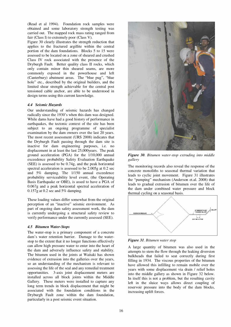
4.5 Bitumen Water-Stops
The water-stop is a primary component of a concrete
dam’s water retention barrier. Damage to the water-
stop to the extent that it no longer functions effectively
can allow high pressure water to enter into the heart of
the dam and adversely influence safety and stability.
The bitumen used in the joints at Waitaki has shown
evidence of extrusion into the galleries over the years,
so an understanding of the mechanism is relevant to
assessing the life of the seal and any remedial treatment
opportunities. 3-axis joint displacement meters are
installed across all block joints within the Middle Gallery. These meters were installed to capture any
long term trends in block displacement that might be
associated with the foundation conditions in the
Dryburgh Fault zone within the dam foundation,
particularly in a post seismic event situation.
Figure 30. Bitumen water-stop extruding into middle
gallery
The monitoring records also reveal the response of the
concrete monoliths to seasonal thermal variation that
leads to cyclic joint movement. Figure 31 illustrates
the “pumping” mechanism (Anderson et.al. 2008) that
leads to gradual extrusion of bitumen over the life of
the dam under combined water pressure and block
thermal cycling on a seasonal basis.
Figure 31. Bitumen water stop
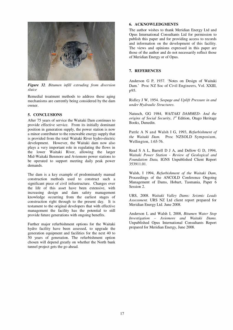
A large quantity of bitumen was also used in the
attempts to stem the flow through the leaking diversion
bulkheads that failed to seat correctly during first
filling in 1934. The viscous properties of the bitumen
have allowed this infilling to remain mobile over the
years with some displacement via drain / relief holes
into the middle gallery as shown in Figure 32 below.
In itself this is not a problem, but the resulting cavity
left in the sluice ways allows direct coupling of reservoir pressure into the body of the dam blocks,
increasing uplift forces.
17
Figure 32. Bitumen infill extruding from diversion
sluice
Remedial treatment methods to address these aging
mechanisms are currently being considered by the dam
owner.
5. CONCLUSIONS
After 75 years of service the Waitaki Dam continues to
provide effective service. From its initially dominant
position in generation supply, the power station is now
a minor contributor to the renewable energy supply that
is provided from the total Waitaki River hydro-electric
development. However, the Waitaki dam now also
plays a very important role in regulating the flows in
the lower Waitaki River, allowing the larger
Mid-Waitaki Benmore and Aviemore power stations to be operated to support meeting daily peak power
demands.
The dam is a key example of predominately manual
construction methods used to construct such a
significant piece of civil infrastructure. Changes over
the life of this asset have been extensive, with
increasing design and dam safety management
knowledge occurring from the earliest stages of
construction right through to the present day. It is
testament to the original developers that with effective management the facility has the potential to still
provide future generations with ongoing benefits.
Further major refurbishment options for the Waitaki
hydro facility have been assessed, to upgrade the
generation equipment and facilities for the next 40 to
50 years of generation. The refurbishment option
chosen will depend greatly on whether the North bank
tunnel project gets the go ahead.
6. ACKNOWLEDGMENTS
The author wishes to thank Meridian Energy Ltd and
Opus International Consultants Ltd for permission to publish this paper and for providing access to records
and information on the development of this facility.
The views and opinions expressed in this paper are
those of the author and do not necessarily reflect those
of Meridian Energy or of Opus.
7. REFERENCES
Anderson G P, 1937. ‘Notes on Design of Waitaki
Dam.’ Proc NZ Soc of Civil Engineers, Vol. XXIII,
p95.
Ridley J W, 1954. Seepage and Uplift Pressure in and
under Hydraulic Structures.
Natusch, GG 1984, WAITAKI DAMMED- And the
origins of Social Security, 1st Edition, Otago Heritage
Books, Dunedin.
Pattle A N and Walsh I G, 1993, Refurbishment of
the Waitaki Dam. Proc NZSOLD Symposium,
Wellington, 1:65-76.
Read S A L, Barrell D J A, and Dellow G D, 1994,
Waitaki Power Station - Review of Geological and
Foundation Data, IGNS Unpublished Client Report
353911.01.
Walsh, I 1994, Refurbishment of the Waitaki Dam,
Proceedings of the ANCOLD Conference Ongoing
Management of Dams, Hobart, Tasmania, Paper 6
Session 2.
URS, 2008. Waitaki Valley Dams: Seismic Loads
Assessment. URS NZ Ltd client report prepared for
Meridian Energy Ltd. June 2008.
Anderson L and Walsh I, 2008, Bitumen Water Stop
Investigation – Aviemore and Waitaki Dams.
Unpublished Opus International Consultants Report
prepared for Meridian Energy, June 2008.