wahme, wahms, wahmv air handlers roduct … handler 01.pdf · product specifications 2 air...
TRANSCRIPT
PRODUCT SPECIFICATIONS
Air Handler.01 www.whirlpoolcomfort.com 4/10
AIR HANDLERS
WAHME, WAHMS, WAHMV
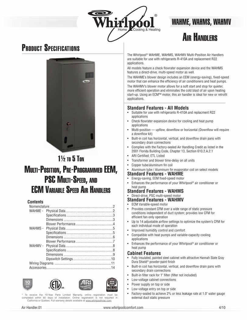
1½ TO 5 TON
MULTI-POSITION, PRE-PROGRAMMED EEM, PSC MULTI-SPEED, AND
ECM VARIABLE SPEED AIR HANDLERS
Standard Features - All Models• Suitable for use with refrigerants R-410A and replacment R22
applications• Check fl owrater expansion device for cooling and heat pump
applications• Multi-position — upfl ow, downfl ow or horizontal (Downfl ow will require
a downfl ow kit)• Built-in coil has horizontal, vertical, and downfl ow drain pans with
secondary drain connections• Complies with the Factory-sealed Air Handling Credit as listed in the
2001 Florida Building Code, Chapter 13, Section 610.2.A.2.1• ARI Certifi ed; ETL Listed• Transformer and blower time-delay on all units• Copper tube/aluminum fi n coil• Aluminum tube / Aluminum fi n evaporator coil on select modelsStandard Features - WAHME• Energy-saving, EEM fi xed-speed motor• Enhances the performance of your Whirlpool® air conditioner or
heat pumpStandard Features - WAHMS• Direct-drive, PSC multi-speed motorStandard Features - WAHMV• ECM Variable-speed motor• Provides constant CFM over a wide range of static pressure
conditions independent of duct system; provides low CFM for effi cient fan-only operation
• Up to 14 adjustable airfl ow settings to optimize the system’s CFM for each individual mode of operation
• Improved humidity control and comfort• Compatible with heat pumps and variable-capacity cooling
applications• Enhances the performance of your Whirlpool® air conditioner or
heat pump
Cabinet Features• Fully insulated, painted steel cabinet with attractive Hannah Slate Gray
Dura Shield® powder-paint fi nish• Built-in coil has horizontal, vertical, and downfl ow drain pans with
secondary drain connections• Built-in fi lter rack for 1" fi lter (fi lter not included)• Low-voltage cabinet connections• Power supply on top or side• Low-voltage entry on top or side• Factory-sealed to achieve 2% or less leakage rate at 1.0" water gauge
external duct static pressure
The Whirlpool® WAHME, WAHMS, WAHMV Multi-Position Air Handlers are suitable for use with refrigerants R-410A and replacement R22 applications.All models feature a check fl owrater expansion device and the WAHMS features a direct-drive, multi-speed motor as well. The WAHME’s blower design includes an EEM (energy-saving), fi xed-speed motor that can enhance the effi ciency of air conditioners and heat pumps.The WAHMV’s blower motor allows for a soft start and stop for quieter, more effi cient operation and eliminates the cold blast of air upon heating start-up. Using an ECM™ motor, this air handler is ideal for new or retrofi t applications.
* To receive the 10-Year Parts Limited Warranty, online registration must be completed within 60 days of installation. Online registration is not required in
California or Québec. Full warranty details available at www.whirlpoolhvac.com.
ContentsNomenclature ......................................................................2WAHME - Physical Data ....................................................2 Specifi cations ...................................................3 Dimensions ......................................................3 Blower Performance .........................................4WAHMS - Physical Data ....................................................5 Specifi cations ...................................................5 Dimensions ......................................................6 Blower Performance .........................................7WAHMV - Physical Data ....................................................8 Specifi cations ...................................................8 Dimensions ......................................................9 Dipswitch Settings ..........................................10Wiring Diagrams ..............................................................11Accessories .......................................................................14
PRODUCT SPECIFICATIONS
2 www.whirlpoolcomfort.com Air Handler.00
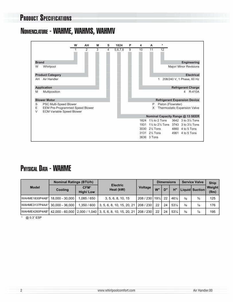
NOMENCLATURE - WAHME, WAHMS, WAHMV
Brand
Electrical
W Whirlpool
Product Category
Refrigerant Charge
4 R-410A
Air HandlerAH
Refrigerant Expansion Device
P Piston (Flowrater)X Thermostatic Expansion Valve
Nominal Capacity Range @ 13 SEER
Application
MultipositionM
Blower Motor
S PSC Multi-Speed BlowerE EEM Pre-Programmed Speed BlowerV ECM Variable Speed Blower
A
11
Engineering
Major/ Minor Revisions
*
12
M
3
1824
5,6,7,8
S
4
AH
21
W
9
P
10
4
3642 3 to 3½ Tons
3743 3 to 3½ Tons
4860 4 to 5 Tons
4961 4 to 5 Tons
1824 1½ to 2 Tons
1931 1½ to 2½ Tons
3030 2½ Tons
3131 2½ Tons
3636 3 Tons
zH06,esahP1,V042/8021
PHYSICAL DATA - WAHME
CoolingCFM¹
High/ LowW" D" H" Liquid Suction
WAHME1830P4AB* 18,000 - 30,000 1,085 / 650 3, 5, 6, 8, 10, 15 208 / 230 19½ 22 46¼ ³⁄₈ ¾ 125
WAHME3137P4AA* 30,000 - 36,000 1,350 / 600 3, 5, 6, 8, 10, 15, 20, 21 208 / 230 22 24 53¼ ³⁄₈ ⁷⁄₈ 176
WAHME4260P4AB* 42,000 - 60,000 2,000 / 1,040 3, 5, 6, 8, 10, 15, 20, 21 208 / 230 22 24 53¼ ³⁄₈ ⁷⁄₈ 195
¹ @ 0.3” ESP
Ship
Weight
(lbs)
egatloVledoM
DimensionsNominal Ratings (BTU/h)Electric
Heat (kW)
Service Valve
PRODUCT SPECIFICATIONS
Air Handler.00 www.whirlpoolcomfort.com 3
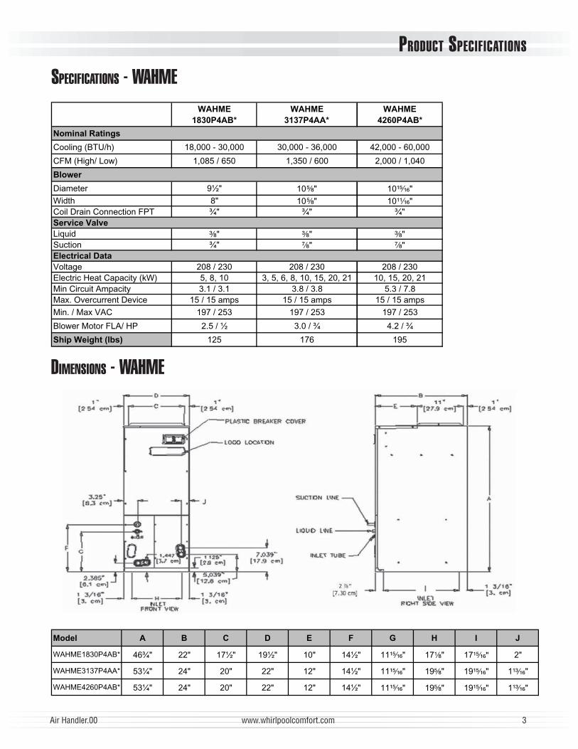
SPECIFICATIONS - WAHMEWAHME
1830P4AB*
WAHME
3137P4AA*
WAHME
4260P4AB*
Nominal Ratings
Cooling (BTU/h) 18,000 - 30,000 30,000 - 36,000 42,000 - 60,000
CFM (High/ Low) 1,085 / 650 1,350 / 600 2,000 / 1,040
Blower
"½9retemaiD 10⁵⁄₈" 10¹⁵⁄₁₆""8htdiW 10⁵⁄₈" 10¹¹⁄₁₆"
"¾"¾"¾TPFnoitcennoCniarDlioCService Valve
Liquid ³⁄₈" ³⁄₈" ³⁄₈""¾noitcuS ⁷⁄₈" ⁷⁄₈"
Electrical Data
032/802032/802032/802egatloVElectric Heat Capacity (kW) 5, 8, 10 3, 5, 6, 8, 10, 15, 20, 21 10, 15, 20, 21Min Circuit Ampacity 3.1 / 3.1 3.8 / 3.8 5.3 / 7.8Max. Overcurrent Device 15 / 15 amps 15 / 15 amps 15 / 15 amps
Min. / Max VAC 197 / 253 197 / 253 197 / 253
Blower Motor FLA/ HP 2.5 / ½ 3.0 / ¾ 4.2 / ¾
Ship Weight (lbs) 591671521
DIMENSIONS - WAHME
Model A B C D E F G H I J
WAHME1830P4AB* 46¾" 22" 17½" 19½" 10" 14½" 11¹⁵⁄₁₆" 17¹⁄₈" 17¹⁵⁄₁₆" 2"
WAHME3137P4AA* 53¼" 24" 20" 22" 12" 14½" 11¹⁵⁄₁₆" 19⁵⁄₈" 19¹⁵⁄₁₆" 1¹³⁄₁₆"
WAHME4260P4AB* 53¼" 24" 20" 22" 12" 14½" 11¹⁵⁄₁₆" 19⁵⁄₈" 19¹⁵⁄₁₆" 1¹³⁄₁₆"
PRODUCT SPECIFICATIONS
4 www.whirlpoolcomfort.com Air Handler.00
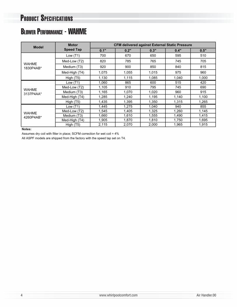
BLOWER PERFORMANCE - WAHME
0.1" 0.2" 0.3" 0.4" 0.5"
Low (T1) 700 670 650 595 510
Med-Low (T2) 820 785 765 745 705
Medium (T3) 920 900 850 840 815
Med-High (T4) 1,075 1,055 1,015 975 960
High (T5) 1,130 1,115 1,085 1,040 1,000Low (T1) 1,060 865 600 515 420
Med-Low (T2) 1,105 910 795 745 690Medium (T3) 1,165 1,070 1,020 960 915
Med-High (T4) 1,285 1,240 1,195 1,140 1,100High (T5) 1,435 1,395 1,350 1,315 1,265Low (T1) 1,445 1,275 1,040 940 855
Med-Low (T2) 1,545 1,405 1,325 1,260 1,145Medium (T3) 1,660 1,610 1,555 1,490 1,415
Med-High (T4) 1,905 1,870 1,810 1,750 1,695High (T5) 2,115 2,070 2,000 1,965 1,915
Notes:
Assumes dry coil with filter in place; SCFM correction for wet coil = 4%
All ASPF models are shipped from the factory with the speed tap set on T4.
WAHME3137P4AA*
WAHME4260P4AB*
ModelMotor
Speed Tap
CFM delivered against External Static Pressure
WAHME1830P4AB*

PRODUCT SPECIFICATIONS
Air Handler.00 www.whirlpoolcomfort.com 5
SPECIFICATIONS - WAHMS
PHYSICAL DATA - WAHMS
CoolingCFM*
High
CFM*
Med
CFM*
LowW" D" H" Liquid Suction
WAHMS1824P4A**18,000 - 24,000
1,025 790 5703, 5, 6, 8, 10,
15208 / 240 15½ 22 42¹⁄₈ ³⁄₈ ¾ 120
WAHMS1931P4A**18,000 - 30,000
1,025 780 5453, 5, 6, 8, 10,
15208 / 240 19½ 22 46¾ ³⁄₈ ⁷⁄₈ 155
30,000 1,330 1,230 9803, 5, 6, 8, 10,
15, 20, 21208 / 240 19½ 22 46¾ ³⁄₈ ⁷⁄₈ 144
36,000 1,230 1,140 9553, 5, 6, 8, 10,
15208 / 240 19½ 22 46¾ ³⁄₈ ¾ 164
WAHMS3642P4A**36,000 - 42,000
1,645 1,440 1,2753, 5, 6, 8, 10,
15, 20, 21208 / 240 22 24 53¼ ³⁄₈ ⁷⁄₈ 173
WAHMS3743P4A**36,000 - 42,000
1,925 1,550 1,3453, 5, 6, 8, 10,
15, 20, 21208 / 240 22 24 53¼ ³⁄₈ ⁷⁄₈ 195
WAHMS4860P4A**48,000 - 60,000
1,985 1,875 1,6503, 5, 6, 8, 10,
15, 20, 21208 / 240 22 24 53¼ ³⁄₈ ⁷⁄₈ 192
WAHMS4961P4A**48,000 - 60,000
1,915 1,795 1,5853, 5, 6, 8, 10,
15, 20, 21208 / 240 22 24 53¼ ³⁄₈ ⁷⁄₈ 192
* @ 0.3” ESP
VoltageModel
Service Valve Ship
Weight
(lbs)
Electric Heat
(kW)
snoisnemiD)h/UTB(sgnitaRlanimoN
WAHMS3030P4A**
WAHMS3636P4A**
WAHMS3642P4AC*36,000 - 42,000
1,625 1,400 1,2503, 5, 6, 8, 10,
15, 20, 21208 / 240 22 24 53¼ ³⁄₈ ⁷⁄₈ 160

PRODUCT SPECIFICATIONS
6 www.whirlpoolcomfort.com Air Handler.00
DIMENSIONS - WAHMS
J
2 ”
[7.30 cm]
Model A B C D E F G H I J
WAHMS1824P4A** 42¹⁄₈" 22" 13½" 15½" 10" 14½" 11¹⁵⁄₁₆" 13¹⁄₈" 17¹⁵⁄₁₆" 2"
WAHMS1931P4A** 46¾" 22" 17½" 19½" 10" 14½" 11¹⁵⁄₁₆" 17¹⁄₈" 17¹⁵⁄₁₆" 2"
WAHMS3030P4A** 46¾" 22" 17½" 19½" 10" 14½" 11¹⁵⁄₁₆" 17¹⁄₈" 17¹⁵⁄₁₆" 2"
2"WAHMS3636P4A** 46¾" 22" 17½" 19½" 10" 14½" 11¹⁵⁄₁₆" 17¹⁄₈" 17¹⁵⁄₁₆"
WAHMS3642P4A** 53¼" 24" 20" 22" 12" 14½" 11¹⁵⁄₁₆" 19⁵⁄₈" 19¹⁵⁄₁₆" 1⁴⁄₅"
WAHMS3743P4A** 53¼" 24" 20" 22" 12" 14½" 11¹⁵⁄₁₆" 19⁵⁄₈" 19¹⁵⁄₁₆" 1⁴⁄₅"
WAHMS4860P4A** 53¼" 24" 20" 22" 12" 14½" 11¹⁵⁄₁₆" 19⁵⁄₈" 19¹⁵⁄₁₆" 1⁴⁄₅"
WAHMS4961P4A** 53¼" 24" 20" 22" 12" 14½" 11¹⁵⁄₁₆" 19⁵⁄₈" 19¹⁵⁄₁₆" 1⁴⁄₅"
PRODUCT SPECIFICATIONS
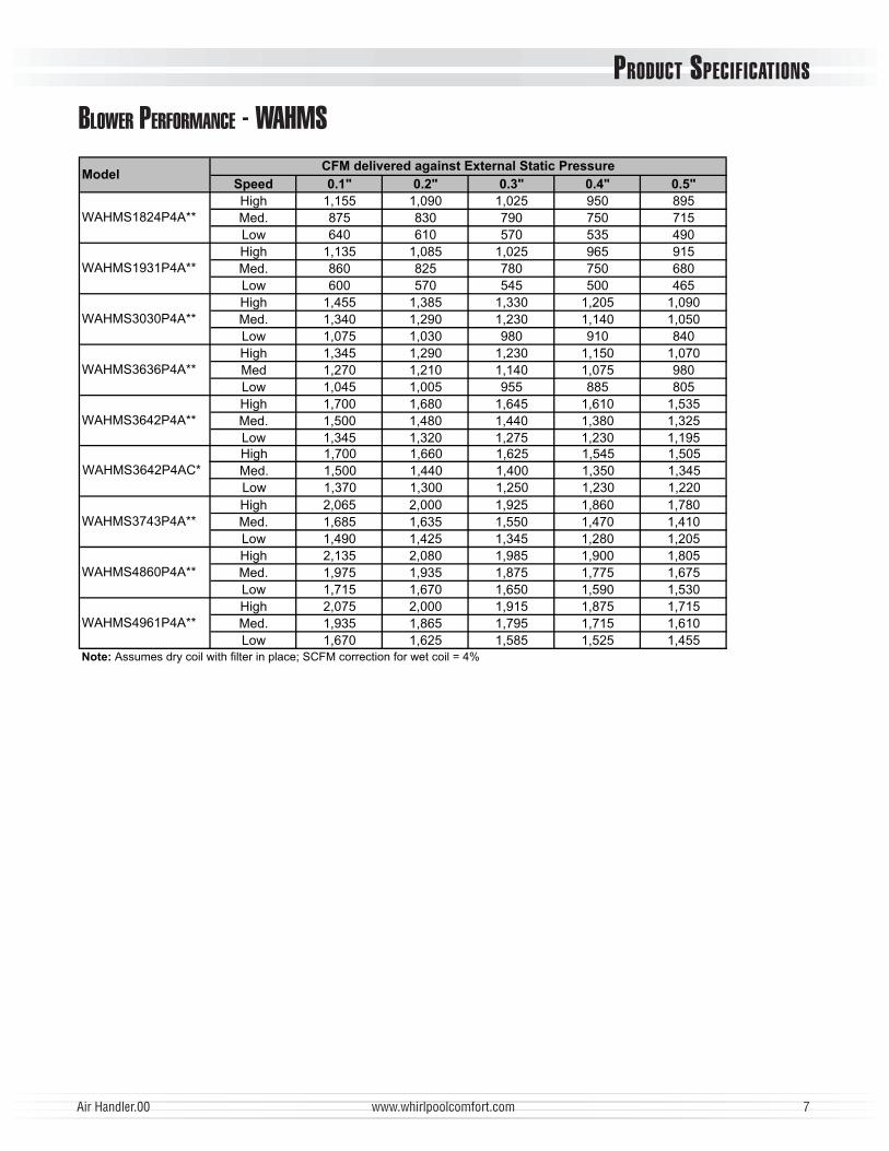
Air Handler.00 www.whirlpoolcomfort.com 7
Speed 0.1" 0.2" 0.3" 0.4" 0.5"
High 1,155 1,090 1,025 950 895Med. 875 830 790 750 715Low 640 610 570 535 490High 1,135 1,085 1,025 965 915Med. 860 825 780 750 680Low 600 570 545 500 465High 1,455 1,385 1,330 1,205 1,090Med. 1,340 1,290 1,230 1,140 1,050Low 1,075 1,030 980 910 840High 1,345 1,290 1,230 1,150 1,070Med 1,270 1,210 1,140 1,075 980Low 1,045 1,005 955 885 805High 1,700 1,680 1,645 1,610 1,535Med. 1,500 1,480 1,440 1,380 1,325Low 1,345 1,320 1,275 1,230 1,195
High 2,065 2,000 1,925 1,860 1,780Med. 1,685 1,635 1,550 1,470 1,410Low 1,490 1,425 1,345 1,280 1,205High 2,135 2,080 1,985 1,900 1,805Med. 1,975 1,935 1,875 1,775 1,675Low 1,715 1,670 1,650 1,590 1,530High 2,075 2,000 1,915 1,875 1,715Med. 1,935 1,865 1,795 1,715 1,610Low 1,670 1,625 1,585 1,525 1,455
Note: Assumes dry coil with filter in place; SCFM correction for wet coil = 4%
ModelCFM delivered against External Static Pressure
WAHMS1824P4A**
WAHMS1931P4A**
WAHMS3030P4A**
WAHMS3636P4A**
WAHMS3642P4A**
WAHMS3743P4A**
WAHMS4860P4A**
WAHMS4961P4A**
High 1,700 1,660 1,625 1,545 1,505Med. 1,500 1,440 1,400 1,350 1,345Low 1,370 1,300 1,250 1,230 1,220
WAHMS3642P4AC*
BLOWER PERFORMANCE - WAHMS
PRODUCT SPECIFICATIONS
8 www.whirlpoolcomfort.com Air Handler.00
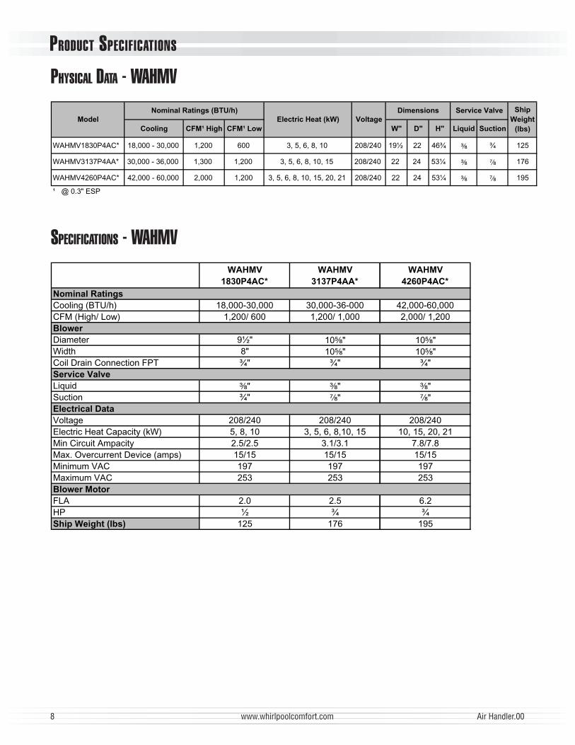
SPECIFICATIONS - WAHMVWAHMV
1830P4AC*
WAHMV
3137P4AA*
WAHMV
4260P4AC*
Nominal Ratings
000,06-000,24000-63-000,03000,03-000,81)h/UTB(gnilooC002,1/000,2000,1/002,1006/002,1)woL/hgiH(MFC
Blower
"½9retemaiD 10⁵⁄₈" 10⁵⁄₈""8htdiW 10⁵⁄₈" 10⁵⁄₈"
Coil Drain Connection FPT ¾" ¾" ¾"Service Valve
Liquid ³⁄₈" ³⁄₈" ³⁄₈""¾noitcuS ⁷⁄₈" ⁷⁄₈"
Electrical Data
042/802042/802042/802egatloVElectric Heat Capacity (kW) 5, 8, 10 3, 5, 6, 8,10, 15 10, 15, 20, 21
8.7/8.71.3/1.35.2/5.2yticapmAtiucriCniMMax. Overcurrent Device (amps) 15/15 15/15 15/15
791791791CAVmuminiM352352352CAVmumixaM
Blower Motor
2.65.20.2ALF¾¾½PH
Ship Weight (lbs) 125 176 195
PHYSICAL DATA - WAHMV
noitcuSdiuqiL"H"D"WwoL¹MFChgiH¹MFCgnilooC
WAHMV1830P4AC* 18,000 - 30,000 1,200 600 3, 5, 6, 8, 10 208/240 19½ 22 46¾ ³⁄₈ ¾ 125
WAHMV3137P4AA* 30,000 - 36,000 1,300 1,200 3, 5, 6, 8, 10, 15 208/240 22 24 53¼ ³⁄₈ ⁷⁄₈ 176
WAHMV4260P4AC* 42,000 - 60,000 2,000 1,200 3, 5, 6, 8, 10, 15, 20, 21 208/240 22 24 53¼ ³⁄₈ ⁷⁄₈ 195
¹ @ 0.3" ESP
Service Valve Ship
Weight
(lbs)
Model Voltage
DimensionsNominal Ratings (BTU/h)
Electric Heat (kW)
PRODUCT SPECIFICATIONS
Air Handler.00 www.whirlpoolcomfort.com 9
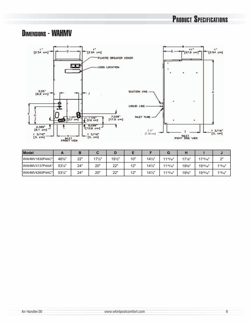
DIMENSIONS - WAHMV
Model A B C D E F G H I J
WAHMV1830P4AC* 46¾" 22" 17½" 19½" 10" 14½" 11¹⁵⁄₁₆" 17¹⁄₈" 17¹⁵⁄₁₆" 2"
WAHMV3137P4AA* 53¼" 24" 20" 22" 12" 14½" 11¹⁵⁄₁₆" 19⁵⁄₈" 19¹⁵⁄₁₆" 1¹³⁄₁₆"
WAHMV4260P4AC* 53¼" 24" 20" 22" 12" 14½" 11¹⁵⁄₁₆" 19⁵⁄₈" 19¹⁵⁄₁₆" 1¹³⁄₁₆"
J
2 ”
[7.30 cm]

PRODUCT SPECIFICATIONS
10 www.whirlpoolcomfort.com Air Handler.00
Dipswitch 1/2/7/8 Dipswitch 5/6/7/8
0381VMHAW0381VMHAW
87658721 Cool Heat Pump
Up to 10 Off Off Off Off 1,100 1,210 2.5 Off Off Off Off 1,100 1,100
Up to 10 On Off Off Off 890 935 2 On Off Off Off 800 800
5 Off On Off Off 700 770 1.5 Off On Off Off 600 600
0624/6303VMHAW0624/6303VMHAW
87658721 Cool Heat Pump
Up to 20 Off Off Off Off 2,050 2,150 5 Off Off Off Off 1,800 1,800
Up to 20 On Off Off Off 1,750 1,835 4 On Off Off Off 1,580 1,580
Up to 15 Off On Off Off 1,600 1,680 3.5 Off On Off Off 1,480 1,480
Up to 10 On On Off Off 1,200 1,260 3 On On Off Off 1,200 1,200
Up to 10 On On Off On 1,020 1,070 2.5 On On Off On 1,020 1,020
7313VMHAW7313VMHAW
87658721 Cool Heat Pump
Up to 20 Off Off Off Off 2,050 2,150 5 Off Off Off Off 1,800 1,800
Up to 20 On Off Off Off 1,750 1,835 4 On Off Off Off 1,580 1,580
Up to 15 Off On Off Off 1,600 1,680 3.5 Off On Off Off 1,480 1,480
Up to 10 On On Off Off 1,200 1,260 3 On On Off Off 1,200 1,200
Up to 10 On On Off On 1,020 1,070 2.5 On On Off On 1,020 1,020
Note: When applying a humidistat (normally closed), refer to the installation and operating instructions. The humidistat can adjust the cooling airflow to 85%.
HeatingElement
(kW)
Switch Position Emergency
Backup
Heat Pump
with Backup
HeatingElement
(kW)
Switch Position Emergency
Backup
Heat Pump
with Backup
Heat Pump
with Backup
Indoor CFM
OutdoorUnit
(Tons)
Switch Position Indoor CFM
OutdoorUnit
(Tons)
Switch Position
OutdoorUnit
(Tons)
Switch Position Indoor CFMEmergency
Backup
HeatingElement
(kW)
Switch Position
DIPSWITCH SETTINGS - WAHMVThe air handler blower motor is pre-programmed for operation at four distinct airfl ow levels when operating in the Cooling, Heat Pump heating, Backup heating (Electric Heating), and Backup + Heat Pump heating modes. Each mode has four levels to deliver different CFM. Simply fl ip the dipswitch for a different CFM combination.
SETTING THE MOTOR ON
OFF
1 2 3 4 5 6 7 8
Dipswitch # Function Instructions
1 Electric Heat ModeSelect the taps allowed in the tables (Dipswitch 1/2/ 7/8) below.
2 Electric Heat Mode
3 N/A N/A
4 Thermostat Mode
ON = The system operates with single-stage units using a single-stage cooling or heat
pump thermostat. (factory default)
OFF = The system operates with two-stage units with either a conventional two-stage cool-
ing/heat pump thermostat or with an encoded two-stage thermostat for cooling operation.
The encoded thermostats can be used with two-stage condensing units in retrofi t
applications where there aren’t enough existing wires available for connections to the
indoor thermostat and outdoor units.
5 Cooling/Heat Pump Mode Find the airfl ow for your application in the tables (Dipswitch 5/6/ 7/8) below. Set up the
motor based on the outdoor unit capacity tons.6 Cooling/Heat Pump Mode
7 Trim CFM Adjust Mode Increase or decrease your selected airfl ow to fi t your requirement.
ON-OFF = Increases selected Cool/Heat Pump airfl ow by 10%.
OFF-ON = Decreases selected Cool/Heat Pump airfl ow by 15%
Note: Other settings have no effect on the set airfl ow.8 Trim CFM Adjust Mode
PRODUCT SPECIFICATIONS
Air Handler.00 www.whirlpoolcomfort.com 11
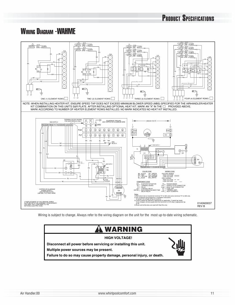
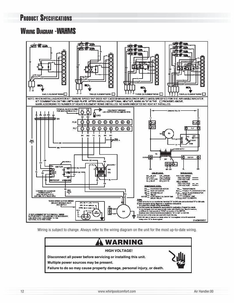
WIRING DIAGRAM -WAHME
Wiring is subject to change. Always refer to the wiring diagram on the unit for the most up-to-date wiring schematic.
BK
BL
BK
L1 L2
BK
BK
HTR1TLHTR2
RD
9
8
7
R
WH
BL
PU
TL
BK
5
6
3
4
PLM
BK
RD
1
2
WH
BK
L2L1
BK
RD
RD
RD
BK
R
HTR1 TL
L1
BK
6
8
9
7
2
RD
PU
4
5
3
BK
RD
1
PLM
BK
L2 L1 L2
RD
YL
M1
M2
BK
RD
YL
RD
R1M4
RDBK
M3
HTR3 TL
HTR2
HTR1 TL
TL
PU
M2
R2
YL
M1
BL
WH
BR
BLRD
BK
RD
BK
TLHTR1
BK
HTR4
HTR3
HTR2
BKRD
9
7
8
L2L1 L1 L2
2
5
6
3
4
PLM
1
RD
M1YL
BK
M2
BL
WH 6
BL
RDBK
YL8
9
7
M6
M5M3
R1
M4
RDPU
M7
R2
M8
BL
TL
TL
TL
YL
BL
RD
BK
RDBL
BR
4
5
3
2
BK
PLM
1
ONE (1) ELEMENT ROWS TWO (2) ELEMENT ROWS THREE (3) ELEMENT ROWS FOUR (4) ELEMENT ROWS
FL
M1
M2
FL
FL
M1
M2
M3
M4
FL
FL
FL
FL
FL
FL
FL
USE COPPER OR ALUMINUM WIRE
COPPER OR ALUMINUMPOWER SUPPLY
(SEE RATING PLATE)USE MIN. 75°C FIELD WIRE
EQUIPMENT GROUND
BL
EM
YL
BL
5
BK
C
BK
PLF
BK
1
RD
2 3
240
24V 4
1 2 3
TR
RD
SEENOTE 4
BL BR
4 5
WH
6 7 8 9
PLM
GRD
1
BK
2 3
RD
L2L1
4 5 6 7 8 9
0140A00037REV B
4) Brown and white wires are used with Heat Kits only.
PLMPLFTR
FACTORY WIRING
FIELD WIRING
1) Red wires to be on transformer terminal "3" for 240 volts and on terminal "2" for 208 volts.2) See composite wiring diagrams in installation instructions
for proper low voltage wiring connections.
Notes:
DELAY RELAY
RELAY
EVAPORATOR MOTOR
ELECTRONIC BLOWER TIME
TERMINAL BOARD R
EM
EBTDR
TB
BKRD
BLYL
BLUE
BLACKREDYELLOW
COMPONENT CODE
BROWNPURPLEGREEN
PUBR
GR
FEMALE PLUG CONNECTORMALE PLUG CONNECTOR
TRANSFORMER
HIGH VOLTAGE LOW VOLTAGE
HIGH VOLTAGE LOW VOLTAGE
PLF 2
COLOR CODE
TR
6 5 PLF4
4 24V 5
SEE NOTE 11 2 3
EM
WIRING CODE
208/240 VOLTS
1
1
PLF
PLM
L1
PLM 2
L2
IF REPLACEMENT OF THE ORIGINAL WIRESSUPPLIED WITH THIS ASSEMBLY IS NECESSARY,USE WIRE THAT CONFORMS TO THENATIONAL ELECTRIC CODE.
SEE NOTE 1
FL FUSE LINKTL THERMAL LIMIT
HTR HEAT ELEMENTS
CR CONTROL RELAY
TERMINAL BLOCK SHOWNFOR 50HZ MODELS ONLY
3) Confirm speed tap selected is appropriate for application. If speed tap needsto be changed, connect purple wire from terminal 4 of CR relay to appropriate tapat TB
MARK ACCORDING TO NUMBER OF HEATER ELEMENT ROWS INSTALLED. NO MARK INDICATES NO HEAT KIT INSTALLED.KIT COMBINATION ON THIS UNIT'S S&R PLATE. AFTER INSTALLING OPTIONAL HEAT KIT, MARK AN "X" IN THE PROVIDED ABOVE.
NOTE: WHEN INSTALLING HEATER KIT, ENSURE SPEED TAP DOES NOT EXCEED MINIMUM BLOWER SPEED (MBS) SPECIFIED FOR THE AIRHANDLER/HEATER
WHITEWH
1 3
52
4
CR
SEE NOTE 2
21 43 5
NC GL
RD
PU
BL
BR
WH
BL
RD
GR
RD
BL
RD
BKRD
C L G N
W2R W1C G 4Y1 OY2 1DH 32 5
3 1
1
C
EM2
43
5
2 4CR
W2R W1C G 4Y1 OY2 1DH 32 5
RD
PU
BR
WH
OR
WH
WH
BL
GR
���
������
RD
BLFUSEHOLDER
FU
SE
HO
LD
ER
5
HIGH VOLTAGE!
WARNING
Disconnect all power before servicing or installing this unit.
Multiple power sources may be present.
Failure to do so may cause property damage, personal injury, or death.
PRODUCT SPECIFICATIONS
12 www.whirlpoolcomfort.com Air Handler.00
WIRING DIAGRAM -WAHMS
Wiring is subject to change. Always refer to the wiring diagram on the unit for the most up-to-date wiring.
HIGH VOLTAGE!
WARNING
Disconnect all power before servicing or installing this unit.
Multiple power sources may be present.
Failure to do so may cause property damage, personal injury, or death.

PRODUCT SPECIFICATIONS
Air Handler.00 www.whirlpoolcomfort.com 13
WIRING DIAGRAMS - WAHMV
Wiring is subject to change. Always refer to the wiring diagram on the unit for the most up-to-date wiring.
HIGH VOLTAGE!
WARNING
Disconnect all power before servicing or installing this unit.
Multiple power sources may be present.
Failure to do so may cause property damage, personal injury, or death.
PRODUCT SPECIFICATIONS
14 www.whirlpoolcomfort.com Air Handler.00
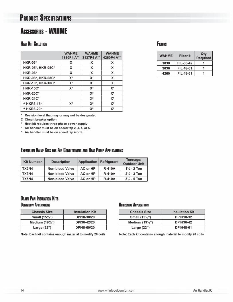
ACCESSORIES - WAHMEFILTERS
WAHME Filter #Qty
Required
1830 FIL-36-42 1
3036 FIL 48-61 1
4260 FIL 48-61 1
DOWNFLOW APPLICATIONS HORIZONTAL APPLICATIONS
Chassis Size Insulation Kit Chassis Size Insulation Kit
Small (15½”) DPI18-30/20 Small (15½”) DPIH18-32
Medium (19½”) DPI36-42/20 Medium (19½”) DPIH36-42
Large (22”) DPI48-60/20 Large (22”) DPIH48-61
Note: Each kit contains enough material to modify 20 coils Note: Each kit contains enough material to modify 20 coils
DRAIN PAN INSULATION KITS
EXPANSION VALVE KITS FOR AIR CONDITIONING AND HEAT PUMP APPLICATIONS
Kit Number Description Application RefrigerantTonnage:
Outdoor Unit
TX2N4 Non-bleed Valve AC or HP R-410A 1½ - 2 Ton
TX3N4 Non-bleed Valve AC or HP R-410A 2½ - 3 Ton
TX5N4 Non-bleed Valve AC or HP R-410A 3½ - 5 Ton
HEAT KIT SELECTION
WAHME
1830P4 A**
WAHME
3137P4 A**
WAHME
4260P4 A**
HKR-03* X X X
HKR-05*, HKR-05C* X X X
HKR-06* X X X
HKR-08*, HKR-08C* X¹ X¹ X
HKR-10*, HKR-10C* X¹ X¹ X
HKR-15C* X² X² X¹
HKR-20C* X² X¹
HKR-21C* X² X¹
^ HKR3-15* X² X² X¹
^ HKR3-20* X² X¹
* Revision level that may or may not be designated
C Circuit breaker option
^ Heat kit requires three-phase power supply
¹ Air handler must be on speed tap 2, 3, 4, or 5.
² Air handler must be on speed tap 4 or 5.

PRODUCT SPECIFICATIONS
Air Handler.00 www.whirlpoolcomfort.com 15
ACCESSORIES - WAHMS
FILTERS
Filter #Qty
Required
1824 FIL 18-32 1
1931 FIL-36-42 1
3030/ 3636 FIL-36-42 1
3642 FIL 48-61 1
3743 FIL 48-61 1
4860/4961 FIL 48-61 1
DRAIN PAN INSULATION KITS
DOWNFLOW APPLICATIONS HORIZONTAL APPLICATIONS
Chassis Size Insulation Kit Chassis Size Insulation Kit
Small (15½”) DPI18-30/20 Small (15½”) DPIH18-32Medium (19½”) DPI36-42/20 Medium (19½”) DPIH36-42
Large (22”) DPI48-60/20 Large (22”) DPIH48-61
Note: Each kit contains enough material to modify 20 coils
EXPANSION VALVE KITS FOR AIR CONDITIONING AND HEAT PUMP APPLICATIONS
Kit Number Description Application RefrigerantTonnage:
Outdoor Unit
TX2N4 Non-bleed Valve AC or HP R-410A 1½ - 2 Ton
TX3N4 Non-bleed Valve AC or HP R-410A 2½ - 3 Ton
TX5N4 Non-bleed Valve AC or HP R-410A 3½ - 5 Ton
WAHMS
1824P4A**
WAHMS
1931P4A**
WAHMS
3030P4A**
WAHMS
3636P4A**
WAHMS
3642P4A**
WAHMS
3743P4A**
WAHMS
4860P4A**
WAHMS
4961P4A**
HKR-03* X X X X X X X X
HKR-05*, HKR-05C* X X X X X X X X
HKR-06* X X X X X X X X
HKR-08*, HKR-08C* X1 X1 X X X X X X
HKR-10*, HKR-10C* X1 X1 X1 X X X X X
HKR-15C* X2 X2 X2 X2 X3 X3 X X
HKR-20C* X2 X3 X3 X X
HKR-21C* X2 X3 X3 X X
^ HKR3-15* X2 X2 X3 X3 X X
^ HKR3-20* X2 X3 X3 X X
* Revision level that may or may not be designated 1 Air handler must either be on medium or high speedC Circuit breaker option 2 Air handler must be on high speed^ Heat kit requires three-phase power supply 3 For static pressure of 0.6 or higher, air handler must be on medium
or high speed
PRODUCT SPECIFICATIONS
16 www.whirlpoolcomfort.com Air Handler.00
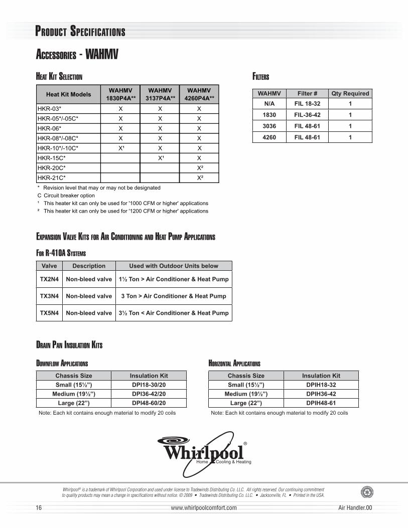
Whirlpool® is a trademark of Whirlpool Corporation and used under license to Tradewinds Distributing Co. LLC. All rights reserved. Our continuing commitment to quality products may mean a change in specifi cations without notice. © 2009 • Tradewinds Distributing Co. LLC. • Jacksonville, FL • Printed in the USA.
ACCESSORIES - WAHMVHEAT KIT SELECTION
Heat Kit ModelsWAHMV
1830P4A**
WAHMV
3137P4A**
WAHMV
4260P4A**
XXX*30-RKH
XXX*C50-/*50-RKH
XXX*60-RKH
HKR-08*/-08C* XXX
HKR-10*/-10C* X¹ X X
X¹X*C51-RKH
HKR-20C* X²
HKR-21C* X²
* Revision level that may or may not be designated
C Circuit breaker option
¹ This heater kit can only be used for '1000 CFM or higher' applications
² This heater kit can only be used for '1200 CFM or higher' applications
EXPANSION VALVE KITS FOR AIR CONDITIONING AND HEAT PUMP APPLICATIONS
FOR R-410A SYSTEMS
Valve Description Used with Outdoor Units below
TX2N4 Non-bleed valve 1½ Ton > Air Conditioner & Heat Pump
TX3N4 Non-bleed valve 3 Ton > Air Conditioner & Heat Pump
TX5N4 Non-bleed valve 3½ Ton < Air Conditioner & Heat Pump
FILTERS
WAHMV Filter # Qty Required
N/A FIL 18-32 1
1830 FIL-36-42 1
3036 FIL 48-61 1
4260 FIL 48-61 1
DRAIN PAN INSULATION KITS
DOWNFLOW APPLICATIONS HORIZONTAL APPLICATIONS
Chassis Size Insulation Kit Chassis Size Insulation Kit
Small (15½”) DPI18-30/20 Small (15½”) DPIH18-32
Medium (19½”) DPI36-42/20 Medium (19½”) DPIH36-42
Large (22”) DPI48-60/20 Large (22”) DPIH48-61
Note: Each kit contains enough material to modify 20 coils Note: Each kit contains enough material to modify 20 coils