waeco coldmachine 54, 55, 84, 85, 86, 87, 94, 95, 96, 97, cs · pdf file86, 87, 94, 95, 96,...
TRANSCRIPT
WAECO ColdMachine 54, 55, 84, 85, 86, 87, 94, 95, 96, 97, CS-NC15
DE 13 KühlaggregatBedienungsanleitung
EN 35 Cooling unitOperating manual
FR 56 Groupe frigorifiqueNotice d’utilisation
ES 80 Unidad frigoríficaInstrucciones de uso
IT 103 Gruppo refrigeranteIstruzioni per l’uso
NL 126 KoelaggregaatGebruiksaanwijzing
DA 148 KøleaggregatBetjeningsvejledning
SV 169 KylaggregatBruksanvisning
NO 190 KjøleaggregatBruksanvisning
FI 211 JäähdytysaggregaattiKäyttöohje
RU 232 Холодильный агрегатИнструкция по эксплуатации
PL 257 Agregat chłodzącyInstrukcja obsługi
CS 279 Chladicí agregátNávod k obsluze
SK 300 Chladiaci agregátNávod na obsluhu
ColdMachine
3
A
1
2
B
23
4
5
6
7
0
1
1
2
1
VD-17
Kompressor einCompressor onCompresseur en fonction
FremdversorgungExternal VoltageAlimentation Extérieure
min max
HauptschalterMain SwitchCommutateurprincipal
TemperatureElectronic
Control
SpeicherabrufDischarge of Cold Accum.Décharge de la Plaque
1
2
3
4
5
6
2
ColdMachine
4
10 m
m
10 m
m
10 mm
10 mm
10 mm
3 VD-01, VD-04, VD-08
min
. 30
mm
4 VD-03
10 m
m
10 m
m
10 mm
5 VD-02, VD-05, VD-18, VD-21
ColdMachine
5
6 VD-06
7
10 mm
1/3
2/3
VD-07, VD-09
1/3
2/3
1 23
4
5
8 VD-14N, VD-15
ColdMachine
6
F
T
DCP
1
gn/ge
brsw
grbl
9 VD-16
0 VD-17
F
T
DCPbl
br1
1
ColdMachine
7
VD-14N, VD-15
1
F
T
DCP
gn/ge
grbl
br
sw
a
cb
2
1
3
d
ColdMachine
8
e 1. 2.
3. 4.
g
SW21
SW21
SW16
SW19
f

ColdMachine
9
SW16
SW212-3 mm
2-3 mm
h
∅/mm²
l/m
12 V 24 V
0 2 4 6 8 10 12 14 16 18 20 22 24 26 2802
6
10
14
i
1 2 3
rt
swblgr/ge
sw/bl
VD-01, VD-02, VD-03, VD-04, VD-05, VD-07,VD-08, VD-09, VD-18, VD-21
23
4
5
6
7
0
1
4
br
j
ColdMachine
10
bl br gn gr rt sw ws
DE Blau Braun Grün Grau Rot Schwarz Weiß oder
EN Blue Brown Green Grey Red Black White or
FR Bleu Marron Vert Gris Rouge Noir Blanc ou
ES Azul Marrón Verde Gris Rojo Negro Blanco o bien
IT Blu Marrone Verde Grigio Rosso Nero Bianco oppure
NL Blauw Bruin Groen Grijs Rood Zwart Wit of
DA Blå Brun Grøn Grå Rød Sort Hvid eller
SV Blå Brun Grön Grå Röd Svart Vit eller
NO Blå Brun Grønn Grå Rød Svart Hvit eller
FI Sininen Ruskea Vihreä Harmaa Punainen Musta Valkoinen tai
RU СинийКоричне-
выйЗеленый Серый Красный Черный Белый или
PL Niebieski Brązowy Zielony SzaryCzer-wony
Czarny Biały lub
CS Modrá Hněda Zelená Šedá Červená Černá Bílá nebo
SK Modrá Hnedá Zelená Sivá Červená Čierna Biela alebo
1 2 3
4
br gn ws
rt
TPC
sw/bl
VD-06k
ColdMachine
11
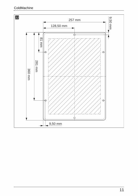
257 mm
81 mm
9,50 mm
9,50 mm
128,50 mm
360 mm
281 mm
l
ColdMachine
12
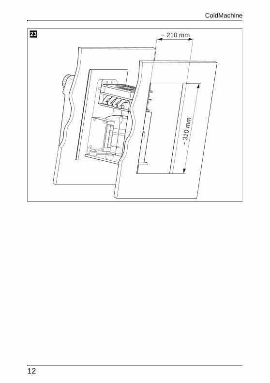
~ 210 mm
~ 31
0 m
m
m
EN
Safety instructions ColdMachine
36
ANOTICE! Failure to observe this instruction can cause material damage and impair the function of the product.
INOTE Supplementary information for operating the product.
➤ Action: This symbol indicates that action is required on your part. The required action is described step-by-step.
✓ This symbol describes the result of an action.
fig. 1 5, page 3: This refers to an element in an illustration. In this case, item 5 in figure 1 on page 3.
2 Safety instructionsThe manufacturer accepts no liability for damage in the following cases:
Faulty assembly or connection
Damage to the product resulting from mechanical influences and excess voltage
Alterations to the product without express permission from the manufacturer
Use for purposes other than those described in the operating manual
2.1 General safety
DDANGER!
Danger of fatalinjuries!When using the device on boats: if the device is powered by the mains, ensure that the power supply has a residual current circuit breaker!
!WARNING!
Have a trained technician make installations in wet rooms.
Do not operate the device if it is visibly damaged.
This device may only be repaired by qualified personnel. Inade-quate repairs can lead to considerable hazards.Should your device need to be repaired, please contact custom-er services.
EN
ColdMachine Safety instructions
37
Do not open the refrigerant circuit under any circumstances. An exception to this is when the device has to be disconnected for return shipping (“Installing the external temperature regulator” on page 43).
Set up the device in a dry location where it is protected against splashing water.
Do not place the device near naked flames or other heat sourc-es (heaters, direct sunlight, gas ovens etc.).
Make sure that the compressor is sufficiently ventilated.
Electronic devices are not toys!Always keep and use the device out of the reach of children.
People (including children) whose physical, sensory or mental capacities or whose lack of experience or knowledge prevent them from using this product safely should not use it without the supervision or instruction of a responsible person.
Before you start up the device for the first time, check that the operatingvoltage matches the battery voltage (see type plate).
If the connection cable is damaged, it must be replaced to pre-vent possible electrical hazards. Only replace a damaged con-nection cable with a connection cable of the same type and specifications.
Do not store any explosive substances, such as spray cans with propellants in the device.
2.2 Operating the device safely
DDANGER! Danger of fatal injuries!
Do not touch exposed cables with your bare hands. This espe-cially applies when operating the device from the AC mains.
ANOTICE!
Never use cleaners that contain sand, acids or solvents to clean the vaporiser.
Protect the device against rain and moisture.
Disconnect the cooling device and other consumer units from the battery before you connect the quick charging device.
EN
Scope of delivery ColdMachine
38
INOTE
Disconnect the device if you are not going to use it for a pro-longed period.
2.3 Safety precautions when handling batteries
!CAUTION! Danger of injury!
Batteries contain aggressive and caustic acids. Avoid battery fluid coming into contact with your body. If your skin does come into contact with battery fluid, wash the part of your body in question thoroughly with water.
If you connect the device to a battery, make sure that no food comes into contact with the battery acid.
3 Scope of delivery
3.1 Accessories
If you wish to operate the cooling unit from the 230 V AC mains, please use one of the following rectifiers.
Available as accessory (not included in scope of delivery):
4 Intended useThe cooling unit is suited for building your own refrigerator or cooler.
Quantity Description
1 Cooling unit or vaporiser
1 Operating manual
Description Item number
WAECO rectifierFor devices with Bd-35F compressor (50/80/CS series)
EPS-100W
WAECO rectifierFor devices with Bd-35F compressor (50/80/CS series)
MPS-35
WAECO rectifierFor devices with Bd-50F compressor (90 series)
MPS-50
EN
ColdMachine Technical description
39
The cooler unit is suitable for cooling and freezing food. The device is also suitable for use on boats.
!CAUTION! Health hazard!Please check if the cooling capacity of the device is suitable for storing the food or medicine you wish to cool.
5 Technical descriptionThe cooling units are suitable for use with 12 V or 24 V DC voltage and can therefore be used for camping or on boats. Furthermore, you can connect them to a 230 V mains supply via the WAECO rectifiers (see “Accessories” on page 38).
When used on boats, the cooling unit can withstand a constant heeling of 30°.
The cooling unit must be used together with a vaporiser. In addition, you can use an accumulator with or without TEC control. The CS-NC15 comprises a cooling unit and a vaporiser.
Use the continuously variable thermostat on the vaporiser to set the desired temperature.
The accumulator and TEC program control ensure a high cooling capacity and improve the unit’s efficiency. The accumulator is charged when there is a sufficient supply of power (for example when powered by a mains adapter). In the event of accumulator usage or under-voltage, the coolant is drawn from the accumulator until it is empty. Thus, no power is taken from the bat-tery during this time.
The TEC program control always ensures that
Cold energy is stored if there is excess electrical energy (external supply of power by a generator).
The coolant accumulator can be used at any time to ensure that the com-plete battery power is used for other consumers.
Stored cold energy is automatically retrieved to preserve the interior cooling temperature of the cooling area, once the battery capacity is exhausted.
EN
Installing the cooling unit ColdMachine
40
INOTE Further information on the coolant accumulator can be found in “Use coolant accumulator” on page 48.
5.1 Battery monitor
The cooling device is equipped with an electronic device to protect against reversing the polarity when connecting to a battery. To protect the battery, the cooling device switches off automatically if the voltage is insufficient (see following table).
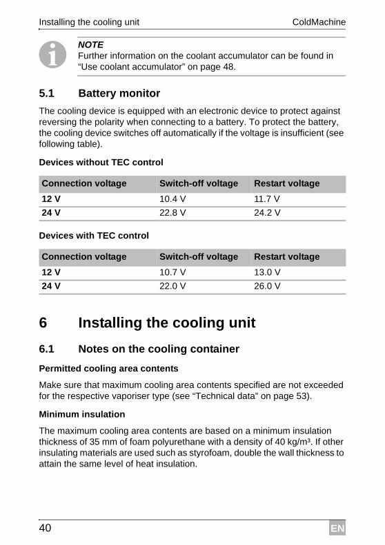
Devices without TEC control
Devices with TEC control
6 Installing the cooling unit
6.1 Notes on the cooling container
Permitted cooling area contents
Make sure that maximum cooling area contents specified are not exceeded for the respective vaporiser type (see “Technical data” on page 53).
Minimum insulation
The maximum cooling area contents are based on a minimum insulation thickness of 35 mm of foam polyurethane with a density of 40 kg/m³. If other insulating materials are used such as styrofoam, double the wall thickness to attain the same level of heat insulation.
Connection voltage Switch-off voltage Restart voltage
12 V 10.4 V 11.7 V
24 V 22.8 V 24.2 V
Connection voltage Switch-off voltage Restart voltage
12 V 10.7 V 13.0 V
24 V 22.0 V 26.0 V
EN
ColdMachine Installing the cooling unit
41
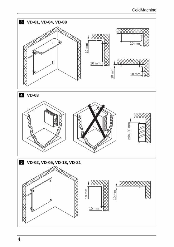
Installing the vaporiser
The vaporiser must be installed in the cooling container (except CS-NC15, the vaporiser is premounted).
➤ Observe the following in the process:
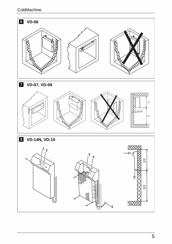
Correct installation position (fig. 3, page 4 up to fig. 0, page 6)
Arrangement in the cooling container as far to the top as possible
Install a least 10 mm from the wall (not VD-14N and VD-15).
ANOTICE! For cooling units without valve couplings (ready-to install units): Do not open the refrigerant circuit during installation. You may have to make the wall openings larger to be able to slide the vaporiser through them (fig. b, page 7). Or alternatively, you create an open-ing that allows you to install the cooling lines at the top (fig. c, page 7).
Connecting the vaporiser
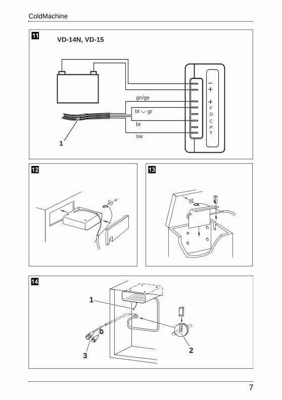
➤ Connect the vaporisers VD-14N and VD-15 in accordance with fig. a, page 7.
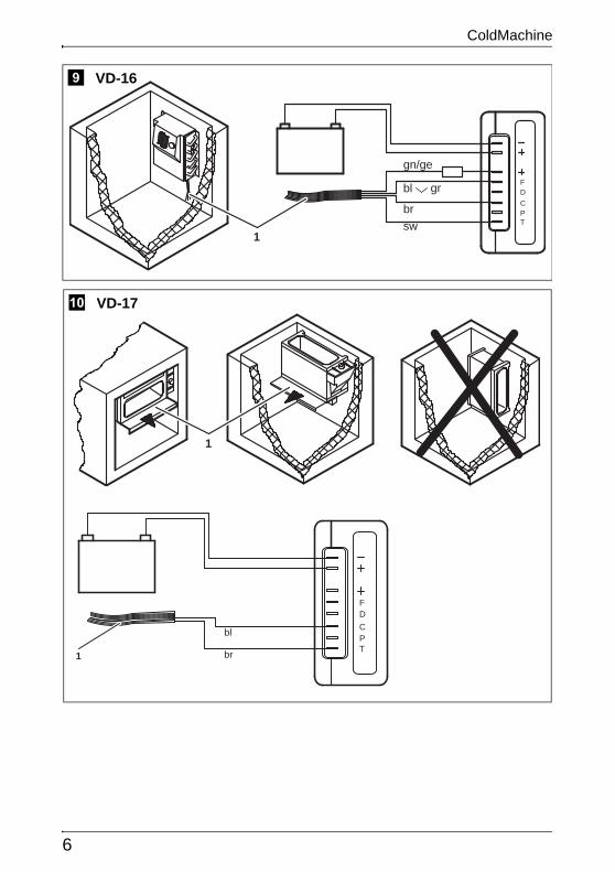
➤ Connect vaporiser VD-16 according to fig. 9, page 6.
➤ Connect vaporiser VD-17 according to fig. 0, page 6.
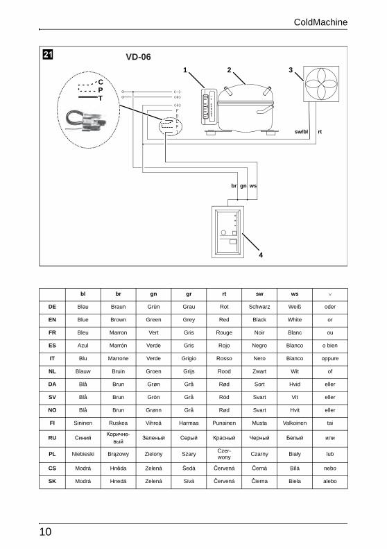
➤ Connect vaporiser VD-06 according to fig. k, page 10.
➤ Connect other vaporisers according to fig. j, page 9.
Keys for the illustrations
No. in fig. 8, page 5
Explanation
1 DC fan
2 Thermostat button
3 Connection plug for DC fan
4 Thermostat
5 Connection cable
No. in fig. 9, page 6
Explanation
1 Connection cable
EN
Installing the cooling unit ColdMachine
42
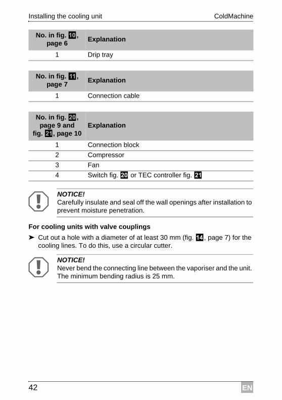
ANOTICE! Carefully insulate and seal off the wall openings after installation to prevent moisture penetration.
For cooling units with valve couplings
➤ Cut out a hole with a diameter of at least 30 mm (fig. d, page 7) for the cooling lines. To do this, use a circular cutter.
ANOTICE! Never bend the connecting line between the vaporiser and the unit. The minimum bending radius is 25 mm.
No. in fig. 0, page 6
Explanation
1 Drip tray
No. in fig. a, page 7
Explanation
1 Connection cable
No. in fig. j, page 9 and
fig. k, page 10Explanation
1 Connection block
2 Compressor
3 Fan
4 Switch fig. j or TEC controller fig. k
EN
ColdMachine Installing the cooling unit
43
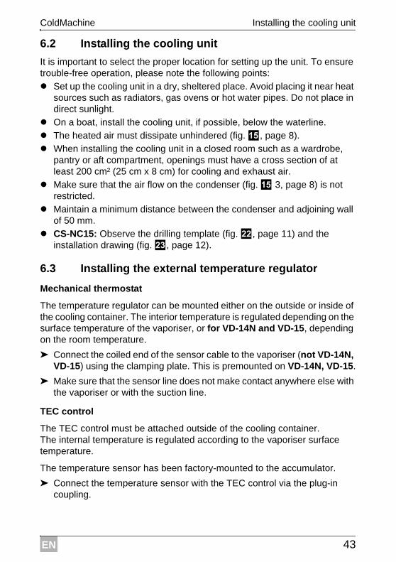
6.2 Installing the cooling unit
It is important to select the proper location for setting up the unit. To ensure trouble-free operation, please note the following points:
Set up the cooling unit in a dry, sheltered place. Avoid placing it near heat sources such as radiators, gas ovens or hot water pipes. Do not place in direct sunlight.
On a boat, install the cooling unit, if possible, below the waterline.
The heated air must dissipate unhindered (fig. e, page 8).
When installing the cooling unit in a closed room such as a wardrobe, pantry or aft compartment, openings must have a cross section of at least 200 cm² (25 cm x 8 cm) for cooling and exhaust air.
Make sure that the air flow on the condenser (fig. e 3, page 8) is not restricted.
Maintain a minimum distance between the condenser and adjoining wall of 50 mm.
CS-NC15: Observe the drilling template (fig. l, page 11) and the installation drawing (fig. m, page 12).
6.3 Installing the external temperature regulator
Mechanical thermostat
The temperature regulator can be mounted either on the outside or inside of the cooling container. The interior temperature is regulated depending on the surface temperature of the vaporiser, or for VD-14N and VD-15, depending on the room temperature.
➤ Connect the coiled end of the sensor cable to the vaporiser (not VD-14N, VD-15) using the clamping plate. This is premounted on VD-14N, VD-15.
➤ Make sure that the sensor line does not make contact anywhere else with the vaporiser or with the suction line.
TEC control
The TEC control must be attached outside of the cooling container. The internal temperature is regulated according to the vaporiser surface temperature.
The temperature sensor has been factory-mounted to the accumulator.
➤ Connect the temperature sensor with the TEC control via the plug-in coupling.
EN
Installing the cooling unit ColdMachine
44
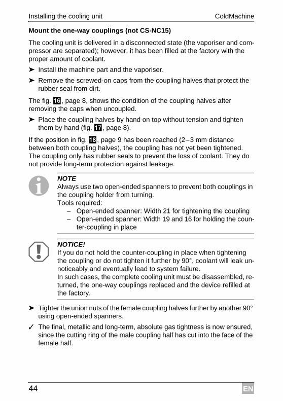
Mount the one-way couplings (not CS-NC15)
The cooling unit is delivered in a disconnected state (the vaporiser and com-pressor are separated); however, it has been filled at the factory with the proper amount of coolant.
➤ Install the machine part and the vaporiser.
➤ Remove the screwed-on caps from the coupling halves that protect the rubber seal from dirt.
The fig. f, page 8, shows the condition of the coupling halves after removing the caps when uncoupled.
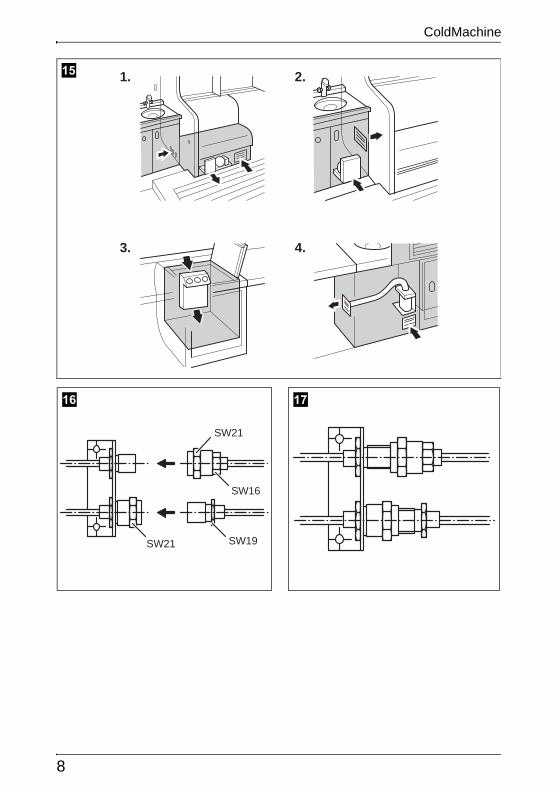
➤ Place the coupling halves by hand on top without tension and tighten them by hand (fig. g, page 8).
If the position in fig. h, page 9 has been reached (2–3 mm distance between both coupling halves), the coupling has not yet been tightened. The coupling only has rubber seals to prevent the loss of coolant. They do not provide long-term protection against leakage.
INOTE Always use two open-ended spanners to prevent both couplings in the coupling holder from turning. Tools required:
– Open-ended spanner: Width 21 for tightening the coupling– Open-ended spanner: Width 19 and 16 for holding the coun-
ter-coupling in place
ANOTICE! If you do not hold the counter-coupling in place when tightening the coupling or do not tighten it further by 90°, coolant will leak un-noticeably and eventually lead to system failure. In such cases, the complete cooling unit must be disassembled, re-turned, the one-way couplings replaced and the device refilled at the factory.
➤ Tighter the union nuts of the female coupling halves further by another 90° using open-ended spanners.
✓ The final, metallic and long-term, absolute gas tightness is now ensured, since the cutting ring of the male coupling half has cut into the face of the female half.
EN
ColdMachine Installing the cooling unit
45
!WARNING! The coolant in the system is under pressure.Wear safety goggles and gloves when disconnecting.
If the device must be decoupled for return shipping, make sure to screw the caps back onto the coupling halves to prevent dirt and moisture from entering the refrigerant circuit.
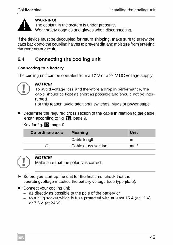
6.4 Connecting the cooling unit
Connecting to a battery
The cooling unit can be operated from a 12 V or a 24 V DC voltage supply.
ANOTICE! To avoid voltage loss and therefore a drop in performance, the cable should be kept as short as possible and should not be inter-rupted.For this reason avoid additional switches, plugs or power strips.
➤ Determine the required cross section of the cable in relation to the cable length according to fig. i, page 9.
Key for fig. i, page 9
ANOTICE! Make sure that the polarity is correct.
➤ Before you start up the unit for the first time, check that the operatingvoltage matches the battery voltage (see type plate).
➤ Connect your cooling unit– as directly as possible to the pole of the battery or– to a plug socket which is fuse protected with at least 15 A (at 12 V)
or 7.5 A (at 24 V).
Co-ordinate axis Meaning Unit
l Cable length m
Cable cross section mm²
EN
Using the cooling unit ColdMachine
46
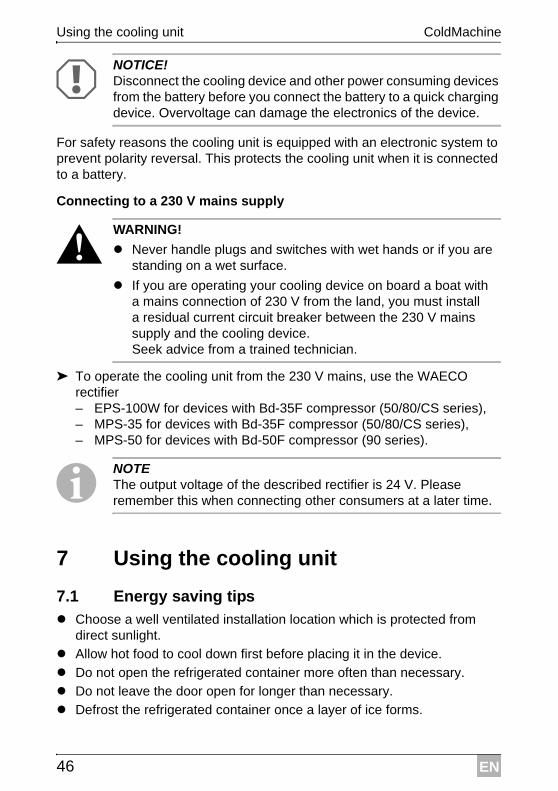
ANOTICE! Disconnect the cooling device and other power consuming devices from the battery before you connect the battery to a quick charging device. Overvoltage can damage the electronics of the device.
For safety reasons the cooling unit is equipped with an electronic system to prevent polarity reversal. This protects the cooling unit when it is connected to a battery.
Connecting to a 230 V mains supply
!WARNING!
Never handle plugs and switches with wet hands or if you are standing on a wet surface.
If you are operating your cooling device on board a boat with a mains connection of 230 V from the land, you must install a residual current circuit breaker between the 230 V mains supply and the cooling device.Seek advice from a trained technician.
➤ To operate the cooling unit from the 230 V mains, use the WAECO rectifier– EPS-100W for devices with Bd-35F compressor (50/80/CS series),– MPS-35 for devices with Bd-35F compressor (50/80/CS series),– MPS-50 for devices with Bd-50F compressor (90 series).
INOTE The output voltage of the described rectifier is 24 V. Please remember this when connecting other consumers at a later time.
7 Using the cooling unit
7.1 Energy saving tips Choose a well ventilated installation location which is protected from
direct sunlight.
Allow hot food to cool down first before placing it in the device.
Do not open the refrigerated container more often than necessary.
Do not leave the door open for longer than necessary.
Defrost the refrigerated container once a layer of ice forms.
EN
ColdMachine Using the cooling unit
47
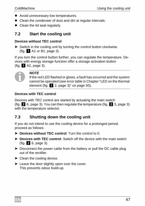
Avoid unnecessary low temperatures.
Clean the condenser of dust and dirt at regular intervals.
Clean the lid seal regularly.
7.2 Start the cooling unit
Devices without TEC control
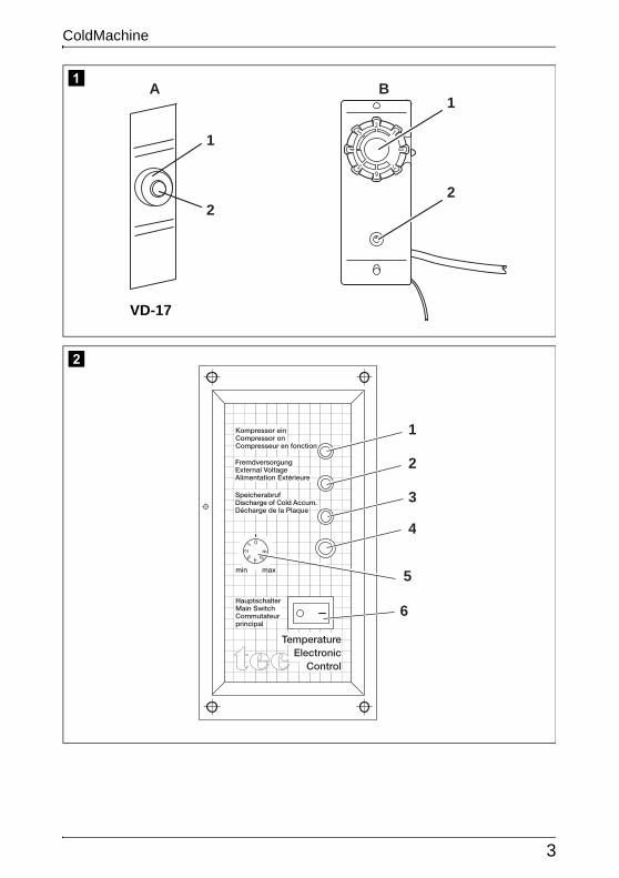
➤ Switch in the cooling unit by turning the control button clockwise (fig. 1 A1 or B1, page 3).
If you turn the control button further, you can regulate the temperature. De-vices with energy storage function offer a storage activation button (fig. 1 A2, page 3).
INOTE If the red LED flashed or glows, a fault has occurred and the system cannot be operated (see error table in Chapter “LED on the thermal element (fig. 1 2, page 3)” on page 50).
Devices with TEC control
Devices with TEC control are started by actuating the main switch (fig. 2 6, page 3). You can then regulate the temperature (fig. 2 5, page 3) with the temperature selector.
7.3 Shutting down the cooling unit
If you do not intend to use the cooling device for a prolonged period, proceed as follows:
➤ Devices without TEC control: Turn the control to 0.
➤ Devices with TEC control: Switch off the device with the main switch (fig. 2 6, page 3).
➤ Disconnect the power cable from the battery or pull the DC cable plug out of the rectifier.
➤ Clean the cooling device.
➤ Leave the door slightly open over the cover.This prevents odour build-up.
EN
Use coolant accumulator ColdMachine
48
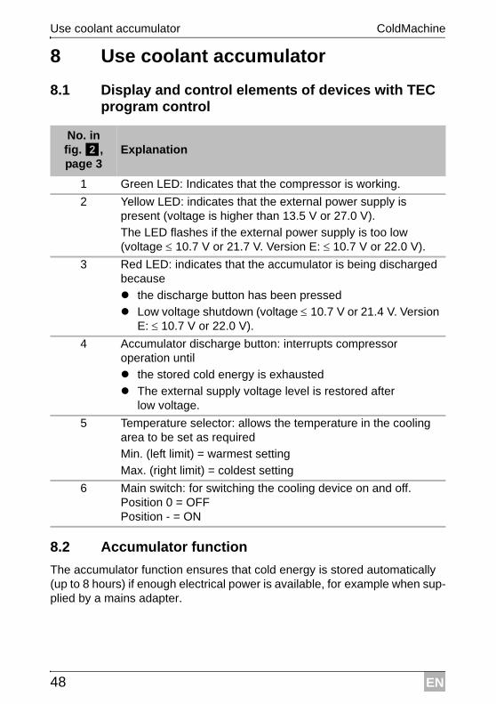
8 Use coolant accumulator
8.1 Display and control elements of devices with TEC program control
8.2 Accumulator function
The accumulator function ensures that cold energy is stored automatically (up to 8 hours) if enough electrical power is available, for example when sup-plied by a mains adapter.
No. in fig. 2, page 3
Explanation
1 Green LED: Indicates that the compressor is working.
2 Yellow LED: indicates that the external power supply is present (voltage is higher than 13.5 V or 27.0 V).
The LED flashes if the external power supply is too low (voltage 10.7 V or 21.7 V. Version E: 10.7 V or 22.0 V).
3 Red LED: indicates that the accumulator is being discharged because
the discharge button has been pressed
Low voltage shutdown (voltage 10.7 V or 21.4 V. Version E: 10.7 V or 22.0 V).
4 Accumulator discharge button: interrupts compressor operation until
the stored cold energy is exhausted
The external supply voltage level is restored after low voltage.
5 Temperature selector: allows the temperature in the cooling area to be set as required
Min. (left limit) = warmest setting
Max. (right limit) = coldest setting
6 Main switch: for switching the cooling device on and off.Position 0 = OFFPosition - = ON
EN
ColdMachine Guarantee
49
Stored cooling power is discharged
automatically when the switch-off voltage is reached (see the table on page 40)
or manually by pressing the discharge button (fig. 1 A2 or fig. 2 4, page 3).
INOTE The cold accumulator can only be discharged manually if it was fully charged beforehand.
The accumulator is automatically charged if,
the restart voltage is exceeded
or the accumulator is empty and you switch the device off and on again using the control button(fig. 2 6, page 3, does only function on VD-06).
ANOTICE! When you are discharging the accumulator, although there is an external supply of power – for example to avoid operating noise from the compressor – use the main switch to switch the unit off (fig. 1 B1 or fig. 2 6, page 3).
INOTE Please remember: Low internal temperature = high current consumption!
9 GuaranteeThe statutory warranty period applies. If the product is defective, please contact the manufacturer's branch in your country (see the back of the instruction manual for the addresses) or your retailer.
For repair and guarantee processing, please include the following docu-ments when you send in the device:
A copy of the receipt with purchasing date
A reason for the claim or description of the fault
EN
Disposal ColdMachine
50
10 Disposal➤ Place the packaging material in the appropriate recycling waste bins
wherever possible.
MIf you wish to finally dispose of the product, ask your local recycling centre or specialist dealer for details about how to do this in accordance with the applicable disposal regulations.
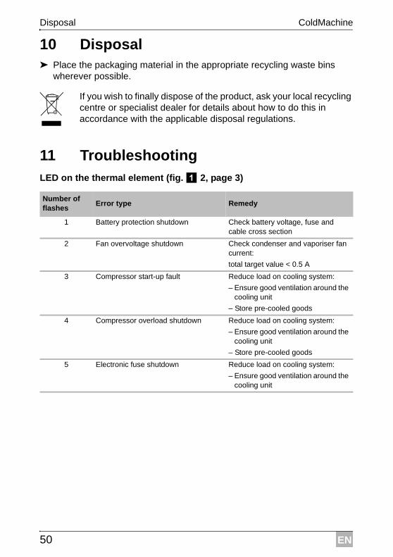
11 TroubleshootingLED on the thermal element (fig. 1 2, page 3)
Number of flashes
Error type Remedy
1 Battery protection shutdown Check battery voltage, fuse and cable cross section
2 Fan overvoltage shutdown Check condenser and vaporiser fan current:
total target value < 0.5 A
3 Compressor start-up fault Reduce load on cooling system:
– Ensure good ventilation around the cooling unit
– Store pre-cooled goods
4 Compressor overload shutdown Reduce load on cooling system:
– Ensure good ventilation around the cooling unit
– Store pre-cooled goods
5 Electronic fuse shutdown Reduce load on cooling system:
– Ensure good ventilation around the cooling unit
EN
ColdMachine Troubleshooting
51
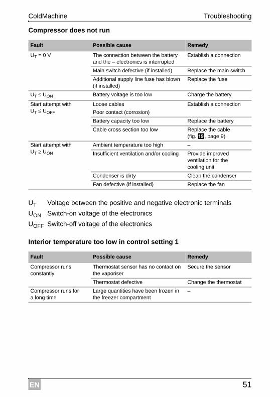
Compressor does not run
Interior temperature too low in control setting 1
Fault Possible cause Remedy
UT = 0 V The connection between the battery and the – electronics is interrupted
Establish a connection
Main switch defective (if installed) Replace the main switch
Additional supply line fuse has blown (if installed)
Replace the fuse
UT UON Battery voltage is too low Charge the battery
Start attempt with UT UOFF
Loose cables
Poor contact (corrosion)
Establish a connection
Battery capacity too low Replace the battery
Cable cross section too low Replace the cable (fig. i, page 9)
Start attempt with UT UON
Ambient temperature too high –
Insufficient ventilation and/or cooling Provide improved ventilation for the cooling unit
Condenser is dirty Clean the condenser
Fan defective (if installed) Replace the fan
UT Voltage between the positive and negative electronic terminals
UON Switch-on voltage of the electronics
UOFF Switch-off voltage of the electronics
Fault Possible cause Remedy
Compressor runs constantly
Thermostat sensor has no contact on the vaporiser
Secure the sensor
Thermostat defective Change the thermostat
Compressor runs for a long time
Large quantities have been frozen in the freezer compartment
–
EN
Troubleshooting ColdMachine
52
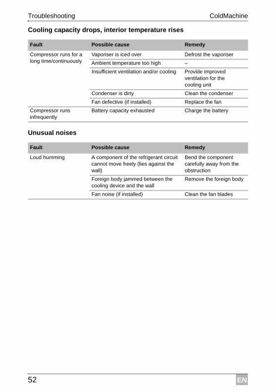
Cooling capacity drops, interior temperature rises
Unusual noises
Fault Possible cause Remedy
Compressor runs for a long time/continuously
Vaporiser is iced over Defrost the vaporiser
Ambient temperature too high –
Insufficient ventilation and/or cooling Provide improved ventilation for the cooling unit
Condenser is dirty Clean the condenser
Fan defective (if installed) Replace the fan
Compressor runs infrequently
Battery capacity exhausted Charge the battery
Fault Possible cause Remedy
Loud humming A component of the refrigerant circuit cannot move freely (lies against the wall)
Bend the component carefully away from the obstruction
Foreign body jammed between the cooling device and the wall
Remove the foreign body
Fan noise (if installed) Clean the fan blades
EN
ColdMachine Technical data
53
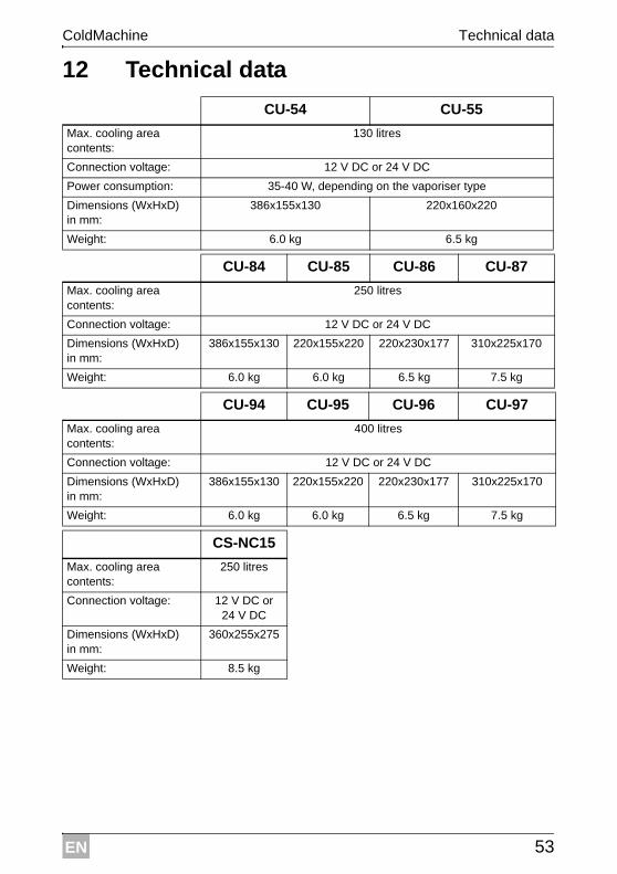
12 Technical data
CU-54 CU-55
Max. cooling area contents:
130 litres
Connection voltage: 12 V DC or 24 V DC
Power consumption: 35-40 W, depending on the vaporiser type
Dimensions (WxHxD) in mm:
386x155x130 220x160x220
Weight: 6.0 kg 6.5 kg
CU-84 CU-85 CU-86 CU-87
Max. cooling area contents:
250 litres
Connection voltage: 12 V DC or 24 V DC
Dimensions (WxHxD) in mm:
386x155x130 220x155x220 220x230x177 310x225x170
Weight: 6.0 kg 6.0 kg 6.5 kg 7.5 kg
CU-94 CU-95 CU-96 CU-97
Max. cooling area contents:
400 litres
Connection voltage: 12 V DC or 24 V DC
Dimensions (WxHxD) in mm:
386x155x130 220x155x220 220x230x177 310x225x170
Weight: 6.0 kg 6.0 kg 6.5 kg 7.5 kg
CS-NC15
Max. cooling area contents:
250 litres
Connection voltage: 12 V DC or 24 V DC
Dimensions (WxHxD) in mm:
360x255x275
Weight: 8.5 kg
EN
Technical data ColdMachine
54
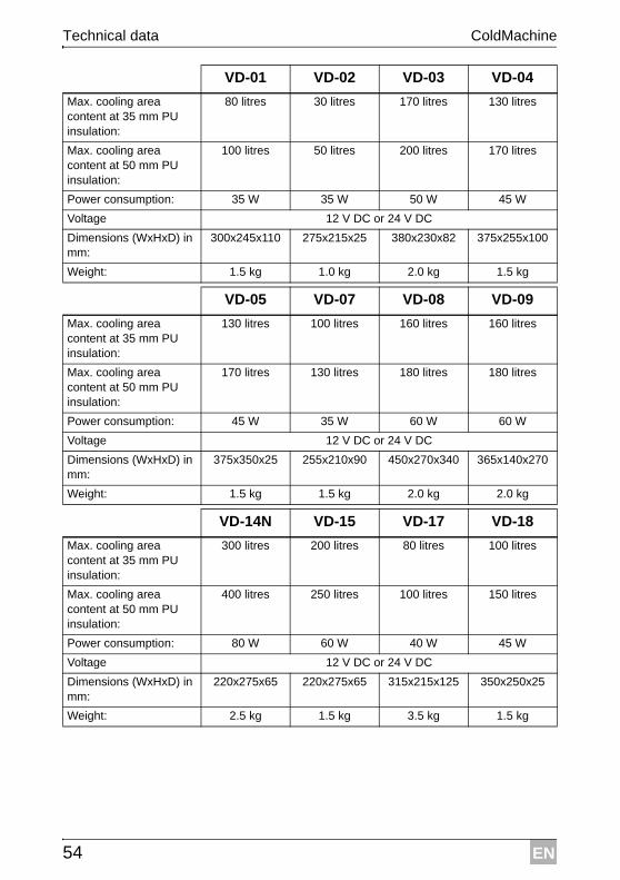
VD-01 VD-02 VD-03 VD-04
Max. cooling area content at 35 mm PU insulation:
80 litres 30 litres 170 litres 130 litres
Max. cooling area content at 50 mm PU insulation:
100 litres 50 litres 200 litres 170 litres
Power consumption: 35 W 35 W 50 W 45 W
Voltage 12 V DC or 24 V DC
Dimensions (WxHxD) in mm:
300x245x110 275x215x25 380x230x82 375x255x100
Weight: 1.5 kg 1.0 kg 2.0 kg 1.5 kg
VD-05 VD-07 VD-08 VD-09
Max. cooling area content at 35 mm PU insulation:
130 litres 100 litres 160 litres 160 litres
Max. cooling area content at 50 mm PU insulation:
170 litres 130 litres 180 litres 180 litres
Power consumption: 45 W 35 W 60 W 60 W
Voltage 12 V DC or 24 V DC
Dimensions (WxHxD) in mm:
375x350x25 255x210x90 450x270x340 365x140x270
Weight: 1.5 kg 1.5 kg 2.0 kg 2.0 kg
VD-14N VD-15 VD-17 VD-18
Max. cooling area content at 35 mm PU insulation:
300 litres 200 litres 80 litres 100 litres
Max. cooling area content at 50 mm PU insulation:
400 litres 250 litres 100 litres 150 litres
Power consumption: 80 W 60 W 40 W 45 W
Voltage 12 V DC or 24 V DC
Dimensions (WxHxD) in mm:
220x275x65 220x275x65 315x215x125 350x250x25
Weight: 2.5 kg 1.5 kg 3.5 kg 1.5 kg
EN
ColdMachine Technical data
55
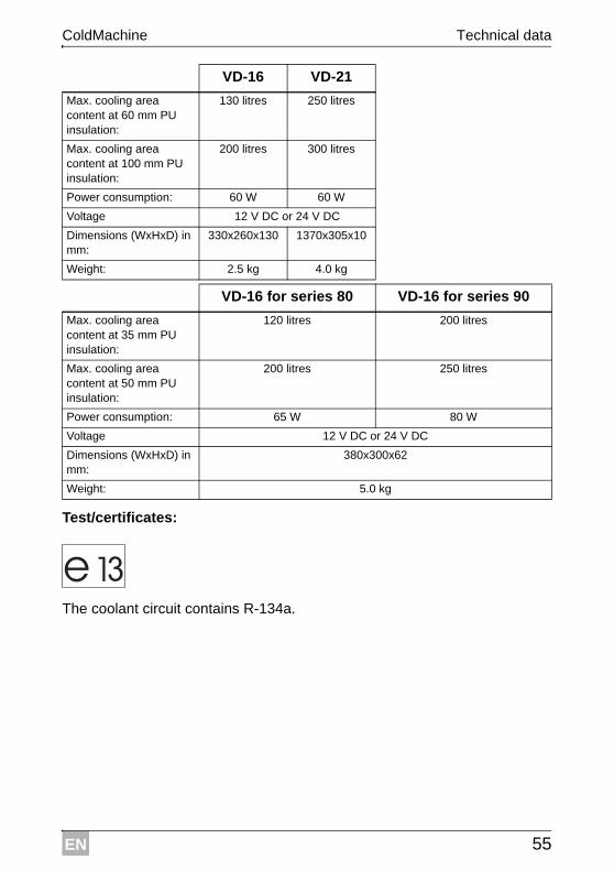
Test/certificates:
The coolant circuit contains R-134a.
VD-16 VD-21
Max. cooling area content at 60 mm PU insulation:
130 litres 250 litres
Max. cooling area content at 100 mm PU insulation:
200 litres 300 litres
Power consumption: 60 W 60 W
Voltage 12 V DC or 24 V DC
Dimensions (WxHxD) in mm:
330x260x130 1370x305x10
Weight: 2.5 kg 4.0 kg
VD-16 for series 80 VD-16 for series 90
Max. cooling area content at 35 mm PU insulation:
120 litres 200 litres
Max. cooling area content at 50 mm PU insulation:
200 litres 250 litres
Power consumption: 65 W 80 W
Voltage 12 V DC or 24 V DC
Dimensions (WxHxD) in mm:
380x300x62
Weight: 5.0 kg