w75cp2 pmo - superior pump...
TRANSCRIPT

INSTRUCTION MANUAL
W75CP2 PMODOUBLE-SEAT MIX PROOF VALVE
FORM NO.: 95-03098 REVISION: 05/2013 READ AND UNDERSTAND THIS MANUAL PRIOR TO OPERATING OR SERVICING THIS PRODUCT.

Information contained in this manual is subject to change without notice and does not represent a commitment on the part of SPX Corporation. No part of this manual may be reproduced or transmitted in any form or by any means, electronic or mechanical, including photocopying and recording, for any purpose, without the express written per-mission of SPX Corporation.
Copyright © 2013 SPX Corporation. All Rights Reserved.
Date: 05/2013
Publication: 95-03098
SPX Flow Technology611 Sugar Creek Road
Delavan, WI 53115 USA
Tel: (800) 252-5200 or (262) 728-1900Fax: (800) 252-5012 or (262) 728-4904
E-mail: [email protected] site: www.spxft.com

05/2013 95-03098 Page 3
Waukesha Cherry-Burrell Table of ContentsWarranty .............................................................................................................. 4
Shipping Damage or Loss ........................................................................................................4Warranty Claim ........................................................................................................................4
Safety .................................................................................................................. 5Care of Stainless Steel ...................................................................................... 6
Stainless Steel Corrosion .........................................................................................................6Elastomer Seal Replacement Following Passivation ...............................................................6
Introduction ........................................................................................................ 7General Information .................................................................................................................7Factory Inspection ....................................................................................................................7Models and Specifications .......................................................................................................7Applications ..............................................................................................................................7Equipment Serial Number ........................................................................................................7Operating Parameters ..............................................................................................................8Seat Options ............................................................................................................................9Pressure Ratings ......................................................................................................................9
Installation ........................................................................................................ 10Location ..................................................................................................................................10Welding Instructions ...............................................................................................................10Air Supply ...............................................................................................................................10Flow Direction ........................................................................................................................10Fittings ....................................................................................................................................10Pipeline Support. ....................................................................................................................11Installing Valve Manifolds .......................................................................................................11Installing the Valve .................................................................................................................11Quality of Control Air to Control Module .................................................................................12
Operation .......................................................................................................... 13Solenoid Valve Port Connections ...........................................................................................13Automatic Fail-Safe System ...................................................................................................14Valve Operating Conditions ...................................................................................................15Test Procedures .....................................................................................................................16
Maintenance ..................................................................................................... 18Maintenance Intervals ............................................................................................................18Inspection ...............................................................................................................................18Lubrication ..............................................................................................................................18Cleaning .................................................................................................................................18Non-Adjustable Seat Cleaning ...............................................................................................19Removing Valve from System ................................................................................................20Disassembly of Valve Stems ..................................................................................................20Adapter Bearings and O-rings ................................................................................................21Tri Ring Seat Replacement ....................................................................................................22Radial Seal Installation ...........................................................................................................22Lower Bearing Carrier O-ring and Bearing Replacement ......................................................23Actuator O-ring and Bearing Replacement ............................................................................24Switches .................................................................................................................................25
Parts Lists ......................................................................................................... 28W75CP2 PMO Double-Seat Mix Proof Valves .......................................................................28W75CP2 PMO Double-Seat Mix Proof Valve Actuator ..........................................................30W75CP2 PMO Double-Seat Mix Proof Valve Bodies ............................................................32
Installation Tools .............................................................................................. 33Troubleshooting ............................................................................................... 34

Warranty Waukesha Cherry-Burrell
Page 4 95-03098 05/2013
Warranty
Seller warrants its products to be free from defect in materials and workmanship for a period of one (1) year from the date of shipment. This warranty shall not apply to products which require repair or replacement due to normal wear and tear or to products which are subjected to accident, misuse or improper mainte-nance. This warranty extends only to the original Buyer. Products manufactured by others but furnished by Seller are exempted from this warranty and are limited to the original manufacturer’s warranty.
Seller’s sole obligation under this warranty shall be to repair or replace any products that Seller determines, in its discretion, to be defective. Seller reserves the right either to inspect the prod-ucts in the field or to request their prepaid return to Seller. Seller shall not be responsible for any transportation charges, duty, taxes, freight, labor or other costs. The cost of removing and/or installing products which have been repaired or replaced shall be at Buyer’s expense.
Seller expressly disclaims all other warranties, express or implied, including without limitation any warranty of merchantabil-ity of fitness for a particular purpose. The foregoing sets forth Seller’s entire and exclusive liability, and Buyer’s exclusive and sole remedy, for any claim of damages in connection with the sale of products. In no event shall Seller be liable for any special consequential incidental or indirect damages (including without limitation attorney’s fees and expenses), nor shall Seller be liable for any loss of profit or material arising out of or relating to the sale or operation of the products based on contract, tort (includ-ing negligence), strict liability or otherwise.
Shipping Damage or Loss If equipment is damaged or lost in transit, file a claim at once with the delivering carrier. The carrier has signed the Bill of Lading acknowledging that the shipment has been received from SPX Flow Technology in good condition. SPX Flow Technology is not responsible for the collection of claims or replacement of materi-als due to transit shortages or damages.
Warranty Claim Warranty claims must have a Returned Goods Authorization (RGA) from the Seller before returns will be accepted.
Claims for shortages or other errors, exclusive of transit short-ages or damages, must be made in writing to Seller within ten (10) days after delivery. Failure to give such notice shall consti-tute acceptance and waiver of all such claims by Buyer.

Waukesha Cherry-Burrell Safety
05/2013 95-03098 Page 5
SafetyREAD AND UNDERSTAND THIS MANUAL PRIOR TO INSTALLING, OPERATING, OR SERVICING THIS EQUIPMENT
Waukesha Cherry-Burrell recommends users of our equipment and designs follow the latest Industrial Safety Standards. At a minimum, these should include the industrial safety requirements established by:
1. Occupational Safety and Health Administration (OSHA), Title 29 of the CFR Section 1910.212- General Requirements for all Machines
2. National Fire Protection Association, ANSI/NFPA 79 ANSI/NFPA 79- Electrical Standards for Industrial Machinery
3. National Electrical Code, ANSI/NFPA 70 ANSI/NFPA 70- National Electrical Code ANSI/NFPA 70E- Electrical Safety Requirement for Employee Workplaces
4. American National Standards Institute, Section B11
Attention: Servicing energized industrial equipment can be hazardous. Severe injury or death can result from electrical shock, burn, or unintended actuation of controlled equipment. Recommended practice is to discon-nect and lockout industrial equipment from power sources, and release stored energy, if present. Refer to the National Fire Protection Association Standard No. NFPA70E, Part II and (as applicable) OSHA rules for Con-trol of Hazardous Energy Sources (Lockout-Tagout) and OSHA Electrical Safety Related Work Practices, including procedural requirements for:
• Lockout-tagout
• Personnel qualifications and training requirements
• When it is not feasible to de-energize and lockout-tagout electrical circuits and equipment before working on or near exposed circuit parts
Locking and Interlocking Devices: These devices should be checked for proper working condition and capa-bility of performing their intended functions. Make replacements only with the original manufacturer’s renewal parts or kits. Adjust or repair in accordance with the manufacturer’s instructions.
Periodic Inspection: Industrial equipment should be inspected periodically. Inspection intervals should be based on environmental and operating conditions and adjusted as indicated by experience. At a minimum, an initial inspection within 3 to 4 months after installation is recommended. Inspection of the electrical control sys-tems should meet the recommendations as specified in the National Electrical Manufacturers Association (NEMA) Standard No. ICS 1.3, Preventative Maintenance of Industrial Control and Systems Equipment, for the general guidelines for setting-up a periodic maintenance program.
Replacement Equipment: Use only replacement parts and devices recommended by the manufacturer to maintain the integrity of the equipment. Make sure the parts are properly matched to the equipment series, model, serial number, and revision level of the equipment.
Warnings and cautions are provided in this manual to help avoid serious injury and/or possible damage to equipment:
DANGER: marked with a stop sign. Immediate hazards which WILL result in severe personal injury or death.
WARNING: marked with a warning triangle. Hazards or unsafe practices which COULD result in severe personal injury or death.
CAUTION: marked with a warning triangle. Hazards or unsafe practices which COULD result in minor personal injury or product or property damage.

Care of Stainless Steel Waukesha Cherry-Burrell
Page 6 95-03098 05/2013
Care of Stainless Steel
Stainless Steel Corrosion Corrosion resistance is greatest when a layer of oxide film is formed on the surface of stainless steel. If film is disturbed or destroyed, stainless steel becomes much less resistant to corro-sion and may rust, pit or crack.
Corrosion pitting, rusting and stress cracks may occur due to chemical attack. Use only cleaning chemicals specified by a repu-table chemical manufacturer for use with 300 series stainless steel. Do not use excessive concentrations, temperatures or exposure times. Avoid contact with highly corrosive acids such as hydrofluoric, hydrochloric or sulfuric. Also avoid prolonged con-tact with chloride-containing chemicals, especially in presence of acid. If chlorine-based sanitizers are used, such as sodium hypochlorite (bleach), do not exceed concentrations of 150 ppm available chlorine, do not exceed contact time of 20 minutes, and do not exceed temperatures of 104°F (40°C).
Corrosion discoloration, deposits or pitting may occur under prod-uct deposits or under gaskets. Keep surfaces clean, including those under gaskets or in grooves or tight corners. Clean immedi-ately after use. Do not allow equipment to set idle, exposed to air with accumulated foreign material on the surface.
Corrosion pitting may occur when stray electrical currents come in contact with moist stainless steel. Ensure all electrical devices connected to the equipment are correctly grounded.
Elastomer Seal Replacement Following Passivation
Passivation chemicals can damage product contact areas of this equipment. Elastomers (rubber components) are most likely to be affected. Always inspect all elastomer seals after passivation is completed. Replace any seals showing signs of chemical attack. Indications may include swelling, cracks, loss of elasticity or any other noticeable changes when compared with new components.

Waukesha Cherry-Burrell Introduction
Introduction
For control top information, please refer to publication 95-03083 (2-piece) or 95-03077 (3-Piece (obsoleted)). For additional product information, please see our web site at www.spx.com/en/waukesha-cherry-burrell/resources/product-literature.
General Information Information in this manual should be read by all personnel involved in installation, setup, operation, and maintenance.
Always use installation tools and lubricants recommended by Waukesha Cherry-Burrell. Waukesha Cherry-Burrell products are subject to intensive intermediate and final leakage and functional tests.
Waukesha Cherry-Burrell Mix Proof valves meet 3-A standards for sanitation, design and style.
W75CP2 PMO Mix Proof valves are double-seat shutoff valves for separating different media. Valves are equipped with a vent separator which creates positive separation of both fluid streams with independent drain paths for visual indication during cleaning and process. Seats are tended by stems equipped with electrical switches capable of signaling whether the upper and/or lower seat is in proper location. W75CP2 PMO valves are air operated (air-to-raise) only.
Factory Inspection Each Waukesha Cherry-Burrell valve is shipped completely assembled, lubricated, and ready for use.
Models and Specifications Materials• Product Wetted: ASTM 316L (UNS-S31603); (DIN-1.4404)
AL6XN upon request
• Non-Product: ASTM 304 (UNS-S30400); (DIN-1.4301)
• Elastomers: FKM (standard); EPDM (optional)
Applications W75CP2 PMO valves allow for separation of milk and milk products from cleaning and sanitizing solutions; single seat lift while milk is in the opposite housing; and are designed for installation in a milk processing system operating in compliance with the Pasteurized Milk Ordinance and M-A-76 Supplement #1. These valves are PMO Section 7, Item 15p(B) compliant, and meet 3-A standards for sanitation and 85 standard for double-seat mix proof valves.
WARNING: PMO Double-seat Mix Proof valves cannot be used to separate raw milk and milk products from pasteurized milk, milk products, and other comestibles.
Equipment Serial Number Waukesha Cherry-Burrell valves are identified by a serial number found on the label on the actuator cylinder.
05/2013 95-03098 Page 7

Introduction Waukesha Cherry-Burrell
Operating Parameters Temperature Range:The recommended operating temperature is determined by the material used for the seals.
No special precautions are required for applications within a tem-perature range of 32°F to 180°F (0°C to 82°C).
For applications above 190°F (88°C), clearances can be affected by excessive thermal expansion when the valve is installed in compact fabrications or manifolds. Valve bodies have thicker cross-sections than tubing, but thermal expansion can affect clearances in interconnecting piping sections.
This valve is NOT designed to be used under aseptic or near aseptic conditions and temperatures.
If operating below 32°F (0°C):
• Control air must have an appropriately low dew point.
• Valve stems must be protected from icing to ensure long working life for valve stem seals.
Solenoid valves may not be used in the control module in room environments below 32°F (0°C) and over 140°F (60°C), as func-tion cannot be guaranteed.
Seal Compatibility
Table 1: Seal Compatibility for FKM/EPDM Seals
Fluorelastomer (FKM) Seals
EPDM Seals
Thermal Range of Application
32°F to 375°F (0°C to 190°C)
0°F to 275°F (-18°C to 135°C)
Chemical Resistance
Silicone oil and grease Silicone oil and grease
Ozone, aging and weather resistant
Ozone, aging and weather resistant
Oils and fats Hot water and steam up to 275°F (135°C)
Aliphatic, chlorinated and aromatic hydrocarbons
Many organic and inorganic acids
Cleaning agents, soda and potassium alkalis
Many polar solvents (alcohols, ketones, esters)
Not compatible with
Superheated steam Mineral oil products (oils, greases and fuels)Formic and acetic
acids
Contact SPX Application Engineering for other fluid compatibility.
FKM and EPDM seals comply with FDA regulations.
Page 8 95-03098 05/2013

Waukesha Cherry-Burrell Introduction
Seat Options NOTE: For higher temperature applications than those listed,please consult the factory. Operating conditions such as flow rate and pressure must be considered when operating near the maxi-mum temperature rating.
SEAT TYPE MATERIAL / MAXIMUM TEMP.
Tri Ring (TR) - Upper FKM
(Std.)
EPDM (opt.)
Operation 350°F (176°C) Sterile (Consult Factory)
or
Operation 280°F (137°C) Sterile 275°F (135°C)
Vent Separator
Radial - Lower
Pressure RatingsParameter Valve Size Pressure Rating
Operating Pressure 2" - 3" 150 psi (10.3 bar)
4" 90 psi (6.2 bar)
Holding Pressure All sizes 150 psi (10.3 bar)
05/2013 95-03098 Page 9

Installation Waukesha Cherry-Burrell
Installation
CAUTION: When installing the valve, ensure that no foreign materials (e.g. tools, screws, welding wire, lubricants, cloths, etc.) are enclosed in the system.
Location The valve must be in a vertical position to ensure that the vent/drain outlet system functions properly.
CAUTION: Isolate products away from the valve prior to performing maintenance.
Locate the valve for easy access for inspection.
Ensure that the valves and pipe systems drain properly. The two-piece body option enables the positions of the connections to be adjusted in relation to each other.
Welding Instructions Prior to installing, thoroughly inspect each valve. When using but-tweld two-piece body valves, clamp connections must be used on either the upper or lower body to allow for servicing of the o-ring seal between the bodies. This does not apply single-piece bod-ies.
CAUTION: Before attempting to buttweld an automatic valve into a line, disassemble the body from the actuator. Dissipate heat away from the valve body to prevent warping.
Mix Proof valves with welded connections require the following to be performed before installation:
• Prior to installation, remove the valve insert (stem and actuator assembly) and lower bearing carrier.
• Remove all seals from the body.
• Weld the body into position, ensuring that the connection is free of tension and distortion.
CAUTION: Welding must be carried out by qualified personnel.
For manifold welding, fixture tables are recommended. Matrix manifold welding requires a controlled deliberate process to maintain the alignment of the parts.
Air Supply The air supply must be 75 to 100 psi (5.2 to 6.9 bar). Install the valves using dry, filtered air. Lubrication is not required. If using lubricated air, refer to the solenoid manufacturer’s specifications.
Flow Direction The valves should be installed to close against the flow to prevent hammering.
Fittings When using suitable fittings, Mix Proof valves with detachable connections can be installed in a pipe system per the fitting requirements. The valve must be installed free of tension. After the valve is installed in the pipe system, attach the control air hoses and connect them to the electrical supply.
Contact SPX at 1-800-252-5200 for more information on our wide variety of fittings for all applications.
Page 10 95-03098 05/2013

Waukesha Cherry-Burrell Installation
Pipeline Support.Figure 1 - Pipeline Support
Install adequate supports to prevent strain on the fittings, valves and equipment connections.
1. Install supports at least every 10 feet on straight runs of pip-ing. (Figure 1, item C).
2. Install supports on both sides of the valves as close as possi-ble to the connections. (Figure 1, item D).
3. Install supports at each change of pipeline direction. (Figure 1, item E and F).
4. For pipelines passing through walls, floors or ceilings, provide at least 1 inch (25 mm) of clearance around the pipe to allow for expansion and contraction. (Figure 1, item G).
CAUTION: In higher temperature applications, ensure proper accommodation for thermal expansion in the pipeline design to minimize stresses on the valve bodies. Excessive mechanical and thermal stresses can distort and damage the valve bodies.
Installing Valve Manifolds Install automatic valve manifolds with a uniform pitch for proper drainage. Elevate one corner of the cluster and pitch 1/16" per foot (1.59 mm per meter) if desired. Arrange the supports for the floor-mounted valve manifolds to provide alignment of the inlet and outlet lines.
Installing the Valve 1. If solenoids are mounted in a control top, connect the air sup-ply lines to “air in.” If solenoids are mounted externally from the control top, connect the air lines as explained in “Solenoid Valve Port Connections” on page 13.
Figure 2 - Control Top Wire Connection Point
VA100-724
A
2. Using caution, lift the valve insert (actuator and stem assem-bly) and set the actuator in the body assembly.
3. Slowly lower the valve insert into the body, making sure the lower stem enters the lower bearing carrier.
4. Supply air to Port 1 (see Figure 3 on page 13), allowing the valve insert to completely drop into the body.
5. Tightly clamp the yoke/body flange.
6. Connect the air lines to 1, 2 and 3, as shown in Figure 3 on page 13.
7. Connect the electrical control cord to the valve at location A (see Figure 2).
NOTE: Control tops are available with strain relief cord grip for hard wiring or threaded pin connectors for quick disconnect. Mating cables must be ordered separately.
8. Operate the valve through the four conditions (closed, open, upper seat cleaning and lower seat cleaning). See Table 2 on page 13.
05/2013 95-03098 Page 11

Installation Waukesha Cherry-Burrell
Quality of Control Air to Control Module
Do not exceed the following values:
• Suspended solids content: Particle size: 5 microns max. Particle Density: 5 mg/m3 max. (= quality class 3)
• Water content: Dewpoint +35°F (+1.6°C) (= quality class 3). For applications at great elevations or at low ambient temperatures, the dewpoint changes.
• Oil content (if possible, without oil): Up to 25mg/m3 max. oil (= quality class 5).
Page 12 95-03098 05/2013

Waukesha Cherry-Burrell Operation
Operation
All functions of W75CP2 PMO valves are pneumatically con-trolled using a 75 min. to 100 max. psi (5.2 to 6.9 bar) clean air supply.
The valve contains a large and small spring in the valve actuator. The springs hold the valve seats in the closed position.
Large Spring
• Located in top air chamber of cylinder.
• Holds valve in the closed position.
Small Spring
• Located in the extended hub of the upper piston.
• When the valve is open, the spring acts on the upper seat stem to hold the upper and lower plugs together.
Solenoid Valve Port Connections
Up to three air supplies, controlled by solenoid valves, supply air to the valve actuator (Figure 3)
Figure 3 - Solenoid Valve Port Connections
VA100-093E
3
1
2
Table 2: Solenoid/Valve Position
Condition Solenoid 1 Solenoid 2 Solenoid 3
Closed OFF OFF OFF
Open ON OFF OFF
Upper Seat Cleaning * OFF ON OFF
Lower Seat Cleaning * OFF OFF ON
1 = Valve Open Inlet Solenoid
2 = Upper Seat Clean Inlet Solenoid*
3 = Lower Seat Clean Inlet Solenoid*
ON = Solenoid energized (OPEN). LED is lit.
OFF = Solenoid de-energized (CLOSED). LED is off.
Solenoids are normally closed.
Air connections are 1/8" NPT x 1/4" push-to-connect poly tube fit-tings.
* Seat lifting requires (2) two additional air supplies.
For specific air-routing and solenoid porting, please refer to con-trol module publications 95-03083 (2-piece) or 95-03077 (3-Piece (obsoleted).
05/2013 95-03098 Page 13

Operation Waukesha Cherry-Burrell
Automatic Fail-Safe System
Table 3: Valve Stem Detection Conditions
Condition Upper Switch (NO)
Lower Switch
(NC)
Yoke Switch (NC)
Switch Symbol
Valve Closed 0 1 1
Valve Open 1 0 0
Valve Closed with Upper Seat Clean*
0 1 0
Valve Closed with Lower Seat Clean*
0 0 1
Notes:
1 = Energized, LED is lit; 0 = De-energized, LED is off
Upper Switch: Sends an input signal when the valve is properly open.
Lower Switch: Sends an input signal when the valve is properly closed.
Yoke Switch: Sends an input signal when the upper seat is properly closed.
* Seat lift during upper seat clean; seat push during lower seat clean, indicator stem lowers.
The valve seats are part of an automatic fail-safe system preventing contamination of the product with cleaning or sanitizing solutions. Automatic fail-safe systems are unique to each particular installation. Typically, both blocking valve seats are properly seated in the blocked position before the mechanical cleaning system can be activated for the cleaning circuit containing the valve arrangement. W75CP2 PMO valves are spring-to-closed fail-safe into the blocked position. Waukesha Cherry-Burrell does not offer control systems, only the PMO double-seat valve.
Page 14 95-03098 05/2013

Waukesha Cherry-Burrell Operation
Valve Operating ConditionsSee Figure 3 on page 13 for port positions.
NOTE: For high-pressure applications, see the recommending closing control sequence listed after “Excess line pressure” in the “Troubleshooting” section on page 34.
Valve Open
The valve is open when Port 1 is pressurized and Ports 3 and 2 are vented.
Valve Closed
The valve is closed when Ports 3, 1 and 2 are vented. The large spring closes the valve to fail-safe position as indicated by the position-detecting proximity switches.
Valve Closed, Upper Seat Lifted
For cleaning the upper seat on seat lifting models only. Port 2 is pressurized, and Ports 3 and 1 are vented.
Valve Closed, Lower Seat Push
For cleaning the lower seat. Port 3 is pressurized, and Ports 1 and 2 are vented. Liquid escapes from the vent and from the lower retainer along the O.D. of the lower balancer.
VA100-776
VA100-775
VA100-778
VA100-777
05/2013 95-03098 Page 15

Operation Waukesha Cherry-Burrell
Test Procedures Yoke-Mounted Proximity Switch
Figure 4 - Proximity Switch Location
C
1/16”
EVA100-780
Adjust the proximity switch (Figure 4, item C) so that it has1/16" clearance above the detection cap (item E), but without compressing it.
Corrective Action: Loosen the proximity switch bolt and adjust the position.
Positive Fail-Safe Detection Test
Perform a test to verify the fully closed fail-safe position. Both the upper and lower valve plugs are position-detectable via proximity switches. Set the valve plug feedback proximity switches for the fully opened and fully closed positions of the valve. See Figure 3 on page 13 for corresponding ports. See Figure 4 to confirm the stem and switch positions have a 1/16" clearance.
Decommission the system, drain the lines and lock out the pumps.
1. With the valve fully closed, confirm that the proximity switches conform to Table 3 on page 14. Verify the switch status on the PLC control system.
2. Pressurize Port 1 to open the valve. Confirm that the proximity switches conform to Table 3 on page 14.
3. Vent Port 1 to close the valve.
4. Activate the upper seat lift either through the control system or manually by supplying air to the air port in Port 2.
5. When the upper seat lifts, confirm that the proximity switches conform to Table 3. Verify the switch status on the PLC control system.
6. Vent the air in Port 2 to deactivate the seat lift.
7. Activate the lower seat push either through the control system or manually by supplying air to Port 3 on the valve actuator.
8. When the lower seat is pushed, confirm that the proximity switches conform to Table 3 on page 14. Verify the switch status on the PLC control system.
9. Vent the air in Port 3 to deactivate the seat lift.
10. Disconnect the air from the valve actuator, placing the valve in the fail-safe position. Verify that the proximity switches register that the valve is fully closed.
Corrective Action: If the Double-seat Mix Proof valve fails to respond as indicated above, immediately check the valve assembly and wiring to locate and correct the cause.
• Check the proximity switch adjustment.
• Check for the correct assembly and adjustment of the valve.
• Check if the valve close control sequence is used. See “Excess line pressure” in the “Troubleshooting” section on page 34.
Page 16 95-03098 05/2013

Waukesha Cherry-Burrell Operation
Confirmation of control system seat lifting interlock during operationThe purpose of this test is for regulatory inspectors to check and confirm that proper controls interlocking of the W75CP2 PMO valve is in place during active CIP operation.
This test is to be performed during active CIP of either the upper or lower housing of the valve. The inspector will manually force open the protected seat lift to confirm proper interlocking.
Procedure
1. Select a W75CP2 test valve for the interlock test. Confirm proper valve assembly and switch status prior to testing (refer to “Positive Fail-Safe Detection Test” on page 16).
2. Choose upper body cleaning or lower body cleaning.
WARNING: Confirm that the product is not present in the valve prior to start and through the duration of this test.
3. Energize CIP for the selected body. Confirm that CIP pressure is present in the selected body.
4. Energize the seat lift of the protected seat:
• Cleaning through the upper body: energize solenoid for lower seat lift.
• Cleaning through the lower body: energize solenoid for upper seat lift.
If the control system interlocking is correct, the CIP supply pump or source will be de-activated.
5. De-energize the seat lift of the protected seat.
Corrective Action
If the control system does not de-activate the cleaning solution pressure, shut down the control system and evaluate and revise the control interlocking.
05/2013 95-03098 Page 17
Maintenance Waukesha Cherry-Burrell
Maintenance
Maintenance Intervals Maintain an adequate stock of replacement parts. Maintenance intervals should be determined by user and specific application, based on the following conditions:
• Daily operation period.
• Switching frequency
• Application parameters, such as temperature, pressure, and flow
• Product type
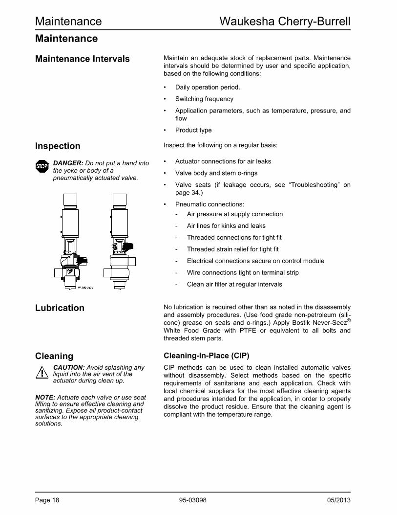
Inspection Inspect the following on a regular basis:
DANGER: Do not put a hand into the yoke or body of a pneumatically actuated valve.
• Actuator connections for air leaks
• Valve body and stem o-rings
• Valve seats (if leakage occurs, see “Troubleshooting” on page 34.)
• Pneumatic connections:
- Air pressure at supply connection
- Air lines for kinks and leaks
- Threaded connections for tight fit
- Threaded strain relief for tight fit
- Electrical connections secure on control module
- Wire connections tight on terminal strip
- Clean air filter at regular intervals
Lubrication No lubrication is required other than as noted in the disassembly and assembly procedures. (Use food grade non-petroleum (sili-cone) grease on seals and o-rings.) Apply Bostik Never-Seez®
White Food Grade with PTFE or equivalent to all bolts and threaded stem parts.
Cleaning Cleaning-In-Place (CIP)
CAUTION: Avoid splashing any liquid into the air vent of the actuator during clean up.
CIP methods can be used to clean installed automatic valves without disassembly. Select methods based on the specific requirements of sanitarians and each application. Check with local chemical suppliers for the most effective cleaning agents and procedures intended for the application, in order to properly dissolve the product residue. Ensure that the cleaning agent is compliant with the temperature range.
NOTE: Actuate each valve or use seat lifting to ensure effective cleaning and sanitizing. Expose all product-contact surfaces to the appropriate cleaning solutions.
Page 18 95-03098 05/2013

Waukesha Cherry-Burrell Maintenance
Cleaning ProcedureMix Proof valves are designed to use a cleaning solution supplied by a CIP system.CAUTION: During valve opening and CIP cleaning, fluid escapes from the drain port. Drain it off to prevent any possible hazard to personnel.
Establish cleaning procedures for each installation depending on product characteristics and operating parameters (temperature, velocity, valve cycles, and product velocities). The valves are 3-A design and intended for CIP cleaning. Consult a local cleaning specialist regarding cleaning of the valves.
CAUTION: Proper cleaning solu-tion pressure is required for proper cleaning of the valve. The CIP pump must be energized during seat lifting.
For seat lifting valves, when the upper or lower body is in CIP, seat movement should occur. Seat cleaning positions are factory-set and marked in the yoke area. Seat cleaning will produce visi-ble leakage from the vent outlet. Brief multiple lifts should occur for each step in the CIP program, excluding the initial rinse.
NOTE: If heavy soils are experienced, seat cleaning is not recommended during the initial rinse.
The lower seat lift cleans the full lower stem product contact area. The cleaning solution exits the valve from both the vent cavity and the balancer O.D.
Maximum Solution Temperature is 160°F (71°C).
Maximum line pressure during seat cleaning is 90 psi (6.2 bar).
Minimum cleaning solution velocity is 5 ft/s (0.3 m/s).
Cleaning time is dependent on the inlet pressure. The recom-mended cycle time is 3 to 5 seconds per cycle after the valve achieves the seat clean position.
Typical cleaning procedures include pulsing the seat during cleaning until the valve has been demonstrated to be clean. This is usually accomplished in 3 to 5 consecutive pulses per step in the CIP program; however, each installation and product varies, so pulsing should continue until all product/debris is removed.
Every few months of operation, remove and inspect one valve in the system to ensure that complete cleaning is being achieved.
Non-Adjustable Seat Cleaning
The seat cleaning movements are fixed at 0.16" upper and 0.28" lower. Confirm the stroke lengths after proper assembly of the upper stem (Figure 7, item B) and nut (Figure 14, item N). Tighten both clockwise until stopped, metal to metal.
05/2013 95-03098 Page 19

Maintenance Waukesha Cherry-Burrell
Removing Valve from System
WARNING: Before removing the actuator/valve stem assembly from the valve body, drain all product lines con-nected to the body.
NOTE: If the valve has a control module with solenoid, air and electric must remain ON until valve is properly disassembled.
1. Clean, rinse, and drain the pipe system elements attached to the valve. Remove or block the fluid and gas lines to prevent material from entering the pipe system elements attached to the valve. If present, disconnect the flush water supply con-nection.
Figure 5 - Location of Adapter Clamp
A
VA100-057a
2. Shut off delivery of the control air unless required for removal of the valve stem/actuator assembly of the body.
3. Disconnect electrical supply and lock out all power.
4. Supply air to open the valve.
5. Remove the clamp between the yoke and the adapter (Figure 5, item A).
6. Remove the air pressure to cycle the valve closed, lifting the valve approximately 3/8" (9.5 mm) out of the body.
7. Lift the complete valve insert (actuator and stems) out of the valve body.
8. Move the valve to a work station.
Disassembly of Valve Stems
Disassembly of the valve stems is required for seat ring replace-ment.
Figure 6 - Valve Stem Removal
A
VA100-077b
Figure 7 - Stem Removal
DVA100-303c
AC
B
1. Using a strap wrench or stem installation tool (see page 33), remove the lower stem (Figure 6, item A) from the actuator by turning it counter-clockwise. To re-install, tighten it clockwise until it is stopped.
2. To remove the upper stem (Figure 7, item B and Figure 8, item 8), turn the stem counter-clockwise and remove it from the actuator. If the adapter (Figure 7, item C) comes out of the yoke, handle it with care. The vent separator is retained to the upper stem. To re-install, tighten it clockwise until it is stopped.
3. See Figure 8 on page 21. To remove the vent separator from the insert, grasp the upper stem (item 8) firmly and unscrew the retaining bolt (item 41).
Table 4: Callout table for Figure 7
A. Lower Stem
B. Upper Stem
C. Top Adapter (Bonnet)
D. Vent Separator (retained to upper stem)
Page 20 95-03098 05/2013
Waukesha Cherry-Burrell Maintenance
52
12
8
25
40
41
53
VA100-782
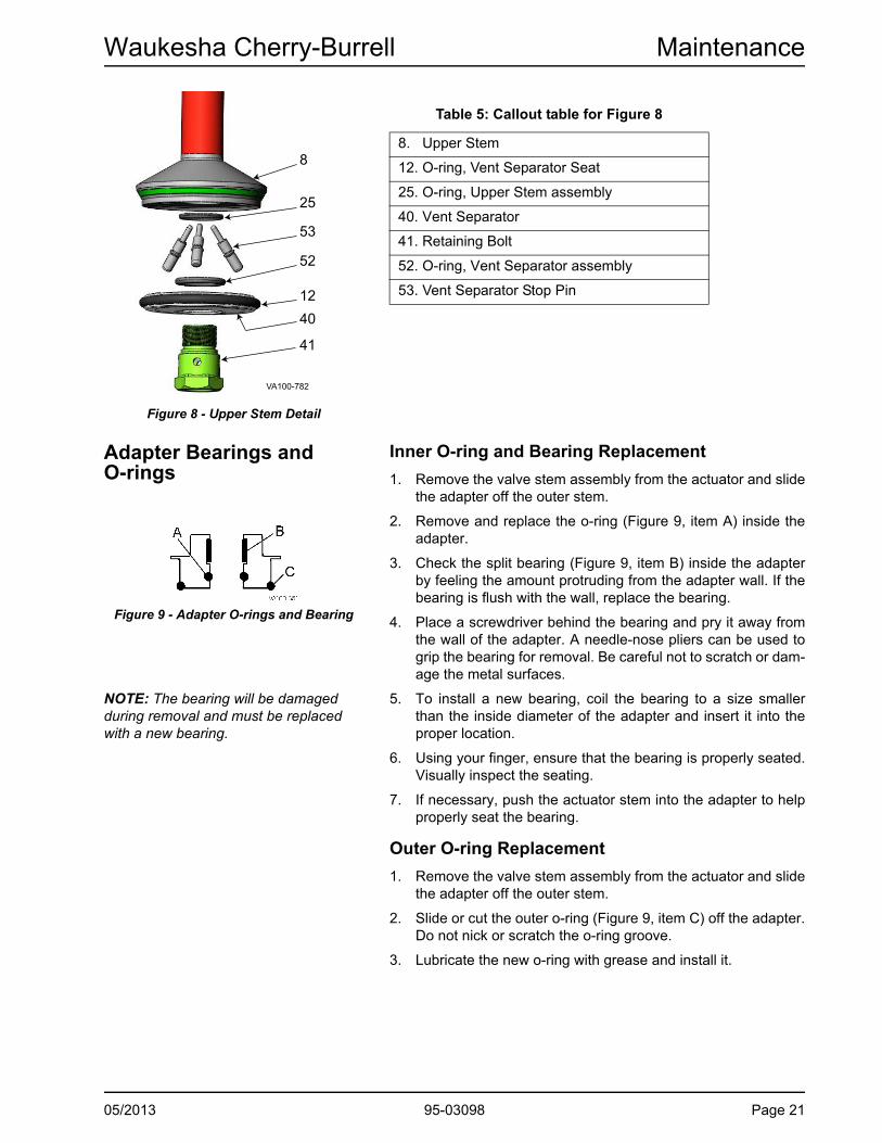
Figure 8 - Upper Stem Detail
Table 5: Callout table for Figure 8
8. Upper Stem
12. O-ring, Vent Separator Seat
25. O-ring, Upper Stem assembly
40. Vent Separator
41. Retaining Bolt
52. O-ring, Vent Separator assembly
53. Vent Separator Stop Pin
Adapter Bearings and O-rings
Inner O-ring and Bearing Replacement
1. Remove the valve stem assembly from the actuator and slide the adapter off the outer stem.
Figure 9 - Adapter O-rings and Bearing
2. Remove and replace the o-ring (Figure 9, item A) inside the adapter.
3. Check the split bearing (Figure 9, item B) inside the adapter by feeling the amount protruding from the adapter wall. If the bearing is flush with the wall, replace the bearing.
4. Place a screwdriver behind the bearing and pry it away from the wall of the adapter. A needle-nose pliers can be used to grip the bearing for removal. Be careful not to scratch or dam-age the metal surfaces.
NOTE: The bearing will be damaged during removal and must be replaced with a new bearing.
5. To install a new bearing, coil the bearing to a size smaller than the inside diameter of the adapter and insert it into the proper location.
6. Using your finger, ensure that the bearing is properly seated. Visually inspect the seating.
7. If necessary, push the actuator stem into the adapter to help properly seat the bearing.
Outer O-ring Replacement
1. Remove the valve stem assembly from the actuator and slide the adapter off the outer stem.
2. Slide or cut the outer o-ring (Figure 9, item C) off the adapter. Do not nick or scratch the o-ring groove.
3. Lubricate the new o-ring with grease and install it.
05/2013 95-03098 Page 21

Maintenance Waukesha Cherry-Burrell
Tri Ring Seat Replacement
Figure 10 - Installing New Tri Ring Seat
B
VA100-082a
A
Figure 11 - Pressing Tri Ring Into Plug
B
VA100-208a
C
D
A
1. Remove the Tri Ring seat by carefully cutting or using an o-ring tool to pull the seat out of the groove. Do not scratch or nick the metal seating surface.
2. Clean the Tri Ring groove after removing the seat.
3. Lubricate the new Tri Ring (Figure 10, item A) with an accept-able cleansing solution or lubricant.
4. Place the stem through a 1-1/8 inch (30 mm) hole bored through a board, secured by a vise. Start the Tri Ring as shown in Figure 11.
NOTE: For part numbers, see “Installation Tools” on page 33.
5. Using the installation tool, press the Tri Ring into the plug at locations A, B, C, and D. If the tool is not used, DO NOT use a knife or any other sharp item that will tear or cut the Tri Ring. To finish installation, press small sections of the seal, alternating from side to side (A-B-C-D), avoiding large loops of seal. When properly installed, the Tri Ring seat lip will pro-trude slightly from the seat edge as shown in Figure 10.
Radial Seal Installation 1. Remove the lower stem radial seal by carefully prying up and cutting the o-ring. Pry up the o-ring and pull it out to remove it. Do not scratch or nick the metal seating surface.
2. Clean the radial seal groove after removal.
3. Ensure that the vent port in the back of the groove is clean and unblocked.
4. Lubricate the o-ring seal and expand it over the stem groove, while trying to avoid twisting the o-ring.
5. Place the assembly tool over the stem and extrude the o-ring seal into the groove by evenly tightening the cap screws on the installation tool. See Figure 12. For a list of installation tools, see page 33.
6. Remove the tool. The dovetail groove permanently retains the o-ring seal.
Figure 12 - Radial Seal Installation
Page 22 95-03098 05/2013

Waukesha Cherry-Burrell Maintenance
Lower Bearing Carrier O-ring and Bearing Replacement1. Remove and replace the o-ring (Figure 13, item A) located inside the lower bearing carrier.
2. Check the split bearing (Figure 13, item B) inside the lower bearing carrier by feeling the amount protruding from the lower bearing carrier wall. If the bearing is flush with the wall, replace the bearing.
Figure 13 - Lower Bearing Carrier
A
B
C
VA100-085
3. Place a screwdriver behind the bearing and pry it away from the wall of the lower bearing carrier. A needle-nose pliers can be used to grip the bearing for removal.
4. To install the new bearing, coil the bearing to a size smaller than the inside diameter of the lower bearing carrier and insert it into the proper location.
5. Push the actuator stem into the lower bearing carrier to help seat the bearing properly.
NOTE: The bearing will be damaged during removal and must be replaced with a new bearing.
6. Using your finger, ensure that the bearing is properly seated. Visually inspect the seating.
7. To remove the outer o-ring (Figure 13, item C), slide or cut the o-ring off the lower bearing carrier. Do not nick or scratch the o-ring groove.
8. Lubricate the new o-ring with grease and install it.
05/2013 95-03098 Page 23

Maintenance Waukesha Cherry-Burrell
Actuator O-ring and Bearing Replacement
CAUTION: The valve stems and actuator must be removed from the valve body before servicing the actuator components.
1. See “Disassembly of Valve Stems” on page 20.
2. Remove the cap screws (Figure 14, item E) and remove the yoke (item F) from the cylinder assembly. Set the yoke aside.
3. Pull the spring cage assembly (item H) and main piston (item J) from the cylinder assembly.
4. Inspect the o-rings (item D). Replace them if worn or dam-aged.
5. Inspect the bearings (item C). If the bearing does not extend slightly above the edge of the metal surface, replace the bearing.
NOTE: The bearing will be damaged during removal and must be replaced with a new bearing.
6. The bearing is split to allow its removal from the groove. Place a screwdriver behind the bearing and pry it away from the wall of the yoke. A needle-nose pliers can be used to grip the bearing for removal. Take care not to gouge or scratch the metal surfaces.
7. Assemble the stack components as shown in Figure 14. Install the yoke and cap screws.
Figure 14 - Actuator Assembly (generic valve assembly shown for reference)
A. Control TopB. Cylinder AssemblyC. BearingD. O-ringE. Cap ScrewF. YokeG. Indicator StemH. Spring Cage AssemblyI. Control Top Mounting Assembly
(see control top manual for detail)J. Main PistonK. Small SpringL. SleeveM. Upper Seat Lifting PistonN. Nut
VA100-533
A
C
D I
E
B
G
H
D
KJ
D
L
DD
M
DC
F
N
D
D
C
D
Page 24 95-03098 05/2013

Waukesha Cherry-Burrell Maintenance
Switches Proximity SwitchFigure 15 - Switch Adjustment
• IP67 sealed, inductive coil switch
• AC/DC
• The position of the actuator stem is detected by a sensor at the target printed on the switch.
Switch Adjustment
W-Series Control Modules with proximity switches or micro switches utilize a positive switching configuration to provide discrete inputs for each valve position.
Lower Switch 1 is normally closed (NC) and passing power when the stem is down. When the stem raises, switch 1 opens and power is stopped.
Upper Switch 2 is normally open (NO) and does not pass power when the stem is down. When the stem is fully raised, Upper Switch 2 closes and passes power.
Figure 16 - Valve Open Adjustment
Proximity switches are supplied with incorporated LED’s which light when power is passed and are inactive when power is stopped.
1. Raise the stem to open, then loosen the cap screws holding the switch blocks (Figure 15, item A) with a 9/64" allen wrench and slide the switches to set the distance between the switches and the stem shaft at 0.040" (1 mm). If using a micro switch, place a 0.020" feeler gauge between the roller and the small diameter of the stem. Adjust the switch toward the stem until a “click” is heard.
2. Hand-tighten the cap screws (Figure 15, item A) to hold the switch position.
3. With the stem raised, adjust the vertical height of the upper switch target to slightly below the stem shoulder (Figure 16). Tighten the cap screws securely.
Figure 17 - Valve Closed Adjustment
4. Lower the stem to close the valve and adjust the target of the lower switch to slightly above the stem shoulder (Figure 17). Tighten the cap screws securely.
CAUTION: Do not over-tighten.
NOTE: Switches should detect stem movement within 1/16 inch (0.062 in/1.58 mm). In this manual, “stem-raised” is understood to be when the valve stem is fully retracted into the actuator. “Stem-lowered” is understood to be when the valve stem is fully extended out from the actuator.
05/2013 95-03098 Page 25

Maintenance Waukesha Cherry-Burrell
Wiring Diagrams
Figure 18 - Strain Relief Proximity Switch
VA100-614
SWITCH AND SOLENOID WIRESTHIS SIDE OF TERMINAL BLOCK
PIN CONNECTORWIRES THIS SIDE OFTERMINAL BLOCK
CABLE STRAIN RELIEF OROPTIONAL PIN CONNECTOR
PINCONNECTOR
SIDE
POLE #1 IDON THIS SIDE
UPPER SWITCH(NORMALLY OPEN)
LOWER SWITCH(NORMALLY CLOSED)
OPTIONAL:ROUTE PMO YOKE PROX SWITCHWIRE THROUGH AT PORT 4 ANDTOP PORT.
USE 1, 2, OR 3 PROX SWITCHES,0, 1, 2, OR 3 SOLENOIDS
AS SPECIFIED ON BILL OF MATERIALPOLE #12 ID
ON THIS SIDE
SOLENOIDLOCATION 1
SOLENOIDLOCATION 2
SOLENOIDLOCATION 3
SWITCH/SOLENOID SIDEGROUND WIRE
GROUND (NOT SHOWN FOR CLARITY)
BROWN (SWITCH COMMON: LOWER, UPPER, YOKE)
BLUE (LOWER SWITCH NC)
BLUE (UPPER SWITCH NO)
BLACK (LOWER SWITCH) 3-WIRE SWITCH ONLY
BLACK (UPPER SWITCH) 3-WIRE SWITCH ONLY
BLACK (SOLENOID 1, 2, 3)BLACK (SOLENOID 1)
BLACK (SOLENOID 2)
BLACK (SOLENOID 3)
BLUE (PMO YOKE PROX SWITCH NC)
BLACK (PMO YOKE PROX SWITCH)3-WIRE SWITCH ONLY
Figure 19: 5-Pin Eurofast with DeviceNet Card, Mix Proof
PIN 2 PIN 1
PIN 4PIN 3
PIN 5
V + ; BROWN (LOWER PROX SWITCH), BROWN (UPPER PROX SWITCH), BROWN (PMO YOKE PROX)
I3; BLACK (PMO PROX SWITCH)
I1; BLACK (LOWER PROX SWITCH)I0; BLACK (UPPER PROX SWITCH)
O3; NOT USEDO2; BLACK (SOLENOID 3)O1; BLACK (SOLENOID 1)O0; BLACK (SOLENOID 2)
V - ; BLUE (LOWER PROX SWITCH), BLUE (UPPER PROX SWITCH), BLACK (SOLENOID 1), BLACK (SOLENOID 2), BLACK (SOLENOID 3), BLUE (PMO YOKE SWITCH)
BLACK (PIN 3 CONNECTOR)BLUE (PIN 5 CONNECTOR)
GRAY (PIN 1 CONNECTOR)WHITE (PIN 4 CONNECTOR)
RED (PIN 2 CONNECTOR)
1X ADDRESS TO BE: 3
10X ADDRESS TO BE: 6
NOTE: USE 120258+ TERMINAL FOR V-, V+
I2; NOT USED
SOLENOIDLOCATION 1
SOLENOIDLOCATION 2
SOLENOIDLOCATION 3
UPPER SWITCH(NORMALLY OPEN)
LOWER SWITCH(NORMALLY CLOSED)
OPTIONAL:ROUTE PMO YOKE PROX SWITCHWIRE THROUGH AT PORT 4 AND TOP PORT.
USE 0,1,2,OR 3 SOLENOIDSAS SPECIFIED ON BILL OF MATERIAL
5 PIN CONNECTORP/N 115761+
VA100-637
Page 26 95-03098 05/2013

Waukesha Cherry-Burrell Maintenance
Figure 20: 4-Pin Eurofast with AS-I Card
VA100-616
BROWN (PMO YOKE PROX)
BLUE (UPPER PROX SWITCH)BROWN(PIN CONNECTOR)
SOLENOID 1
SOLENOID 3
BLUE(PIN CONNECTOR)
SOLENOID 2
BROWN (LOWER PROX SWITCH)
BLUE (LOWER PROX SWITCH)
BLUE (PMO YOKE PROX)
BROWN (UPPER PROX SWITCH)
PIN 1PIN 2
PIN 3 PIN 4
4 PIN CONNECTORCUT BACK AND TAPEWHITE (PIN 2) AND BLACK (PIN 4) WIRESP/N 113600+
OPTIONAL:ROUTE PMO YOKE PROX SWITCHWIRE THROUGH AT PORT 4 AND TOP PORT.
SOLENOIDLOCATION 3
SOLENOIDLOCATION 2
SOLENOIDLOCATION 1
USE 0, 1, 2, OR 3 SOLENOIDS AS SPECIFIED ON BILL OF MATERIAL.
UPPER SWITCH(NORMALLY OPEN)
LOWER SWITCH(NORMALLY CLOSED)
05/2013 95-03098 Page 27

Parts Lists Waukesha Cherry-Burrell
Parts Lists
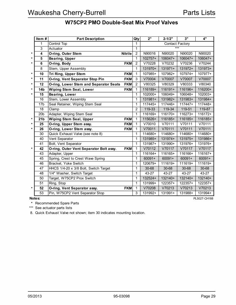
W75CP2 PMO Double-Seat Mix Proof Valves
50
5
25
41
14b161517b
12
43
20
21b 86
45
10
6
51
4
52
40
42
5311
18
48
47
46
30
1, 1a
26
VA100-773
5
25
41
12
43
20
21b 86
45
10
52
40
42
53
11
18
26 VA100-783
Stem Detail
Exploded View, upper stem
52
12
8
25
40
41
53
VA100-782
Page 28 95-03098 05/2013
Waukesha Cherry-Burrell Parts Lists
W75CP2 PMO Double-Seat Mix Proof ValvesItem # Qty 2" 2-1/2" 3" 4"1 Control Top 13 Actuator 1
* 4 O-ring, Outer Stem Nitrile 2 N90016 N90020 N90020 N90020
* 5 Bearing, Upper 1 102757+ 106047+ 106047+ 106047+
* 6 O-ring, Body FKM 2 V70228 V70232 V70236 V70244
8 Stem, Upper Assembly 1 131970+ 131971+ 131972+ 131973+
* 10 Tri Ring, Upper Stem FKM 1 107985+ 107982+ 107974+ 107977+
* 11 O-ring, Vent Separator Stop Pin FKM 3 V70004 V70007 V70007 V70007
* 12 O-ring, Lower Stem and Separator Seats FKM 2 V80325 V80329 V80333 V80340
* 14b Wiping Stem Seal, Lower FKM 1 116189+ 116191+ 116196+ 116200+
* 15 Bearing, Lower 1 102000+ 106049+ 106048+ 102003+16 Stem, Lower Assembly 1 131981+ 131982+ 131983+ 131984+
17b Seal Retainer, Wiping Stem Seal 1 117445+ 117446+ 117447+ 117448+18 Clamp 2 119-33 119-34 119-51 119-87
20b Adapter, Wiping Stem Seal 1 116169+ 116170+ 116273+ 116172+
* 21b Wiping Stem Seal, Upper FKM 1 115626+ 116185+ 116185+ 116185+
* 25 O-ring, Upper Stem assy. FKM 1 V70010 V70111 V70111 V70111
* 26 O-ring, Lower Stem assy. FKM 1 V70011 V70111 V70111 V7011130 Quick Exhaust Valve (see note 8) 1 114680+ 114680+ 114680+ 114680+40 Vent Separator 1 131985+ 131974+ 131975+ 131986+41 Bolt, Vent Separator 1 131987+ 131990+ 131976+ 131976+
* 42 O-ring, Outer Vent Separator Bolt assy. FKM 1 V70112 V70117 V70117 V7011743 Adapter, Upper 1 116164+ 116165+ 116166+ 116167+45 Spring, Crest to Crest Wave Spring 1 60091+ 60091+ 60091+ 60091+46 Bracket, Yoke Switch 1 120679+ 111619+ 111619+ 111619+47 HHCS 1/4-20 x 3/8 Bolt, Switch Target 1 30-68 30-68 30-68 30-6848 1/4" Washer, Switch Target 1 43-27 43-27 43-27 43-2750 Target, W75CP2 Prox Switch 1 132524+ 132140+ 132140+ 132140+51 Ring, Stop 1 131999+ 122357+ 122357+ 122357+
* 52 O-ring, Vent Separator assy. FKM 1 V70208 V70213 V70213 V7021353 Pin, W75CP2 Vent Separator Stop 3 131992+ 131991+ 131988+ 131994+
Notes: PL5027-CH188
* Recommended Spare Parts*** See actuator parts lists8. Quick Exhaust Valve not shown; item 30 indicates mounting location.
Part DescriptionContact Factory
***
05/2013 95-03098 Page 29

Parts Lists Waukesha Cherry-Burrell
W75CP2 PMO Double-Seat Mix Proof Valve Actuator
24
8
23
20
4
1, 1a
22
9
14
29
17
16
15
26
11
6 5
12
7
10
18
VA100-774
Page 30 95-03098 05/2013

Waukesha Cherry-Burrell Parts Lists
W75CP2 PMO Double-Seat Mix Proof Valve ActuatorItem # Qty 2" 2.5", 3", 4"
1 Indicator Stem - Visual 1 106050+ 106003+
1a Indicator Stem - Control Top 1 107951+ 131010+
4 Cylinder 1 113099+ 113112+
* 5 Bearing, Indicator Stem 1 102757+ 102757+
* 6 O-ring, Indicator Stem Nitrile 1 N70210 N70210
* 7 O-ring, Cylinder Nitrile 1 N70240 N70255
* 8 O-ring, Upper Seat Piston Nitrile 2 N70342 N70433
9 Cap Screw, 1/4-20 x 3/8 lg. 30-68 (qty 4) 30-68 (qty 8)
10 Piston & Spring Assembly 1 113679+ 122039+
* 11 O-ring, Adjusting Sleeve, Outer Nitrile 2 N70214 N70219
12 Yoke 2" 120761+ --
2.5" -- 120762+
3" -- 128101+
4" -- 128127+
* 14 Bearing, Main Piston 2 101995+ 102052+
* 15 Bearing, Lifting Piston 1 109820+ 109920+
* 16 Bearing 1 106047+ 109919+
* 17 O-ring, Adjusting Sleeve, Inner Nitrile 1 N70222 N70328
18 Spring, Upper Stem 1 101946+ 128072+
20 Nut, Upper Seat Clean 1 131995+ 122345+
22 Main Piston 1 117215+ 129932+
23 Upper Seat Piston 2" 1 131997+ 124543+
24 Adjusting Sleeve 2" 1 117439+ 116469+
* 26 O-ring, adjustment collar Nitrile 1 N80026 N90222
* 29 O-ring, Lower Seat Piston Nitrile 1 N70337 N70427
Notes: PL5027-CH190
* Recommended Spare Parts
1
Part Description
05/2013 95-03098 Page 31

Parts Lists Waukesha Cherry-Burrell
W75CP2 PMO Double-Seat Mix Proof Valve Bodies
Item # Part Description 2" 2-1/2" 3" 4"
1 Buttweld - A1 130760+ 129946+ 129961+ 131018+
2 Buttweld - B1 130762+ 129948+ 129963+ 131020+
3 Buttweld - B2 130763+ 129949+ 129964+ 131021+
4 Buttweld - B3 130764+ 129950+ 129965+ 131022+
5 Buttweld - C1 130761+ 129947+ 129962+ 131019+
6 Buttweld - E1 130759+ 129945+ 129960+ 131017+PL5027-CH189
Page 32 95-03098 05/2013

Waukesha Cherry-Burrell Installation Tools
05/2013 95-03098 Page 33
Installation Tools
Tri Ring Tool
VA100-082b
Tri Ring Tool 102797+PL5027-CH85
Seal Insertion Collar Tool
VA100-664
Valve Size 2" 2-1/2" 3" 4"
Part No. 120049+ 120051+ 120053+ 120055+
PL5027-CH67a
W75CP2 Stem Installation Tool
VA100-784
Valve Size 2" 2-1/2" 3" 4"
Part No. 132172+ 132173+ 132174+ 132175+
PL5027-CH191
Mix Proof Valve Lifter
VA100-716a
Stainless-steel chain is adjustable on the lifting bar to accommodate tight overhead clearances.
Lifting clamp is attached to the actuator base.
Provides lift at the balance point to allow easy maneuvering of the valve in crowded settings.
Valve Model, Size Part No.
2-1/2" through 4" O.D. 127036+
PL5027-CH156D

Troubleshooting Waukesha Cherry-Burrell
Troubleshooting
PROBLEM POSSIBLE CAUSE SUGGESTED ACTION
Leakage
Leakage from vent/drain with valve closed
Upper or lower seat ring failure Remove valve. Replace seat rings.
Debris trapped in upper seat or lower seat
Inspect/change cleaning procedure to correct.
Upper or lower seat not closed Inspect inner and outer stems for galling and burrs on adapter.
Check actuator function.
Upper or lower seat clean activated
Check control sequence.
Leakage from vent/drain with valve open
Blocker radial seal failed Replace seal.
Valve seats not meshed together Inspect inner and outer stems for galling and burrs.
Small spring not holding upper stem in place
Check and replace small spring and stems in actuator.
Leakage around yoke Internal adapter o-ring failure Replace o-ring.
External adapter o-ring failure Replace o-ring.
Leakage through outer stem Inner stem o-ring failure Replace o-ring.
Operation
Valve fails to open Air pressure too low Set air pressure to 72 psi (5 bar) minimum.
Control failure Check control sequence.
Check control wiring and power source.
Valve fails to close Controls failed Check control sequence.
Check control wiring and power source.
Excess line pressure A short air pulse to Port #3 is recommended after the valve is closed for precise positioning of the stems, to allow accurate sensing of the valve closed condition. Typical valve close control sequence:1. De-energize solenoid #1
2. Delay 10 seconds
3. Pulse Solenoid #3 on for 1 second
For solenoid valve port connections, see Figure 3 on page 13.
Page 34 95-03098 05/2013

Waukesha Cherry-Burrell Troubleshooting
Upper or lower seat fails to lift during seat lift
Actuator seal failure or no air Confirm no air leaks from the actuator.
Confirm solenoid operation.
Actuator moves when valve opened
Clamp loose Tighten clamp with valve open.
Electrical
No valve closed or open indication
Lower switch not adjusted properly
Adjust switch. See “Switch Adjustment” on page 25.
No valve open signal. Upper switch not adjusted Adjust switch. See “Switch Adjustment” on page 25.
Moisture in switch housing Missing and/or damaged gaskets Replace gaskets.
PROBLEM POSSIBLE CAUSE SUGGESTED ACTION
05/2013 95-03098 Page 35
Troubleshooting Waukesha Cherry-Burrell
Notes
Page 36 95-03098 05/2013

W75CP2 PMODOUBLE-SEAT MIX PROOF VALVE
SPX FLOW TECHNOLOGY
611 Sugar Creek Road
Delavan, WI 53115
P: (262) 728-1900 or (800) 252-5200
F: (262) 728-4904 or (800) 252-5012
SPX reserves the right to incorporate our latest design and material changes
without notice or obligation.
Design features, materials of construction and dimensional data, as described in
this bulletin, are provided for your information only and should not be relied upon
unless confirmed in writing.
Please contact your local sales representative for product availability in your
region. For more information visit www.gowcb.com.
The green “>” is a trademark of SPX Corporation, Inc.
ISSUED: 05/2013
COPYRIGHT © 2013 SPX Corporation