vw mk4/b5/b5.5 colormfa install guide · vw mk4/b5/b5.5 colormfa install guide ... this is an...
TRANSCRIPT

VW MK4/B5/B5.5 ColorMFA Install Guide ColorMFA from AutoPilot. Instructions from Clusters by Litke and pinout from Drive2
This is an overview guide on how to install the v3.2/v3.4 ColorMFA units into MK4/B5/B5.5 VDO clusters.
This is a general step by step guide and will be touching on pinouts, helpful tips, required modifications, and
differences between the different cluster options. This will not cover basics such as soldering techniques, how to
read/edit/flash eeprom (in case of lowline clusters needing outside temp byte changed), or how to disassemble
the cluster. By Litke LLC and Matthew Litke are not responsible for any damages you may cause to yourself,
your cluster, or your vehicle during this process.
ColorMFA Kit Contents:
-Main PCB, LCD, 0.12mm^2 wire, 0.35mm^2 wire, SMD resistors, beeper, matte film screen protector.
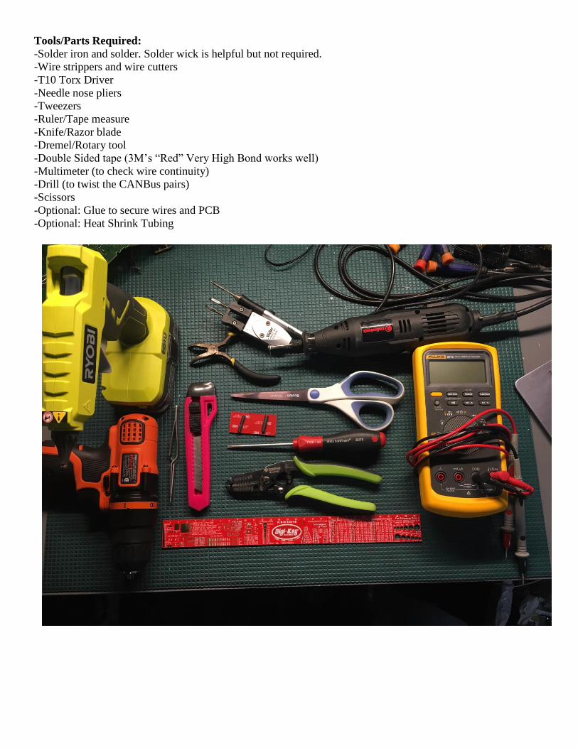
Tools/Parts Required:
-Solder iron and solder. Solder wick is helpful but not required.
-Wire strippers and wire cutters
-T10 Torx Driver
-Needle nose pliers
-Tweezers
-Ruler/Tape measure
-Knife/Razor blade
-Dremel/Rotary tool
-Double Sided tape (3M’s “Red” Very High Bond works well)
-Multimeter (to check wire continuity)
-Drill (to twist the CANBus pairs)
-Scissors
-Optional: Glue to secure wires and PCB
-Optional: Heat Shrink Tubing

Install Steps
• Prepare ColorMFA PCB o Cut the smaller gauge wire into 14 pieces (15 if FIS) in 300mm lengths each.
o Cut 5 more pieces of the smaller gauge wire in 150mm lengths.
o Cut the larger gauge wire in 3 equal pieces of roughly 230mm lengths.
o Solder these cut wires to the ColorMFA PCB as shown the diagram above. Route the wires through
the bottom of the PCB for a cleaner looking install. The large gauge is for Ground, 12V, and Ignition.
The 150mm pieces will be used for the beepers, Trinput 1, Trinput 2, and Trinput 8. Mark CAN High
on both Comfort and motor with a marker than twist Motor CAN H and L together with the drill and
twist Comfort CAN H and L together.
o If the car you’re fitting this unit to does not have an oil level sensor inside the oil pan, connect
Trinput 1 (Oil Level Sensor warning) to the Ignition pad (PWR Pin 3) otherwise the oil level warning
light will appear due to no oil level sensor. If the car has a sensor in the pan, skip this step.
o Bunch the wires into 3 groups. 1 to go to the blue connector, 1 for green connector, and 1 for the
center warning lights. The beeper wires can go to the blue connector group. Heat shrink tubing can
be used for the glue and green group to keep them organized and also prevent chaffing when
routing the wires through the PCB openings.
o Attach double sided tape to the backside of the PCB. Doubling up 2 pieces of 3M VHB provides good
spacing between the cluster and ColorMFA PCBs and ensures the LCD won’t sit too high or too low
with regards to the face when installed.
• Cluster Disassembly
o Remove the lens. It is attached with 2 T10 screws and 8 clips (6 on top, 2 on bottom).
o Remove back plastic housing. This is held onto the PCB with 1 hook on the far left and 1 hook on the
far right.
o Remove the needles by twisting counter clockwise while pulling up then remove faces.
o Remove the clock and odometer screen cage by bending the hooks and lifting them out.
o Remove the white plastic light shroud. There are hooks that need to be pressed on the backside of
the PCB to release it. The odometer reset knob will also need to be pressed through the PCB.
o Remove the clock adjustment knob by pulling the black plastic apart from the white portion then
pushing the white portion through the PCB.
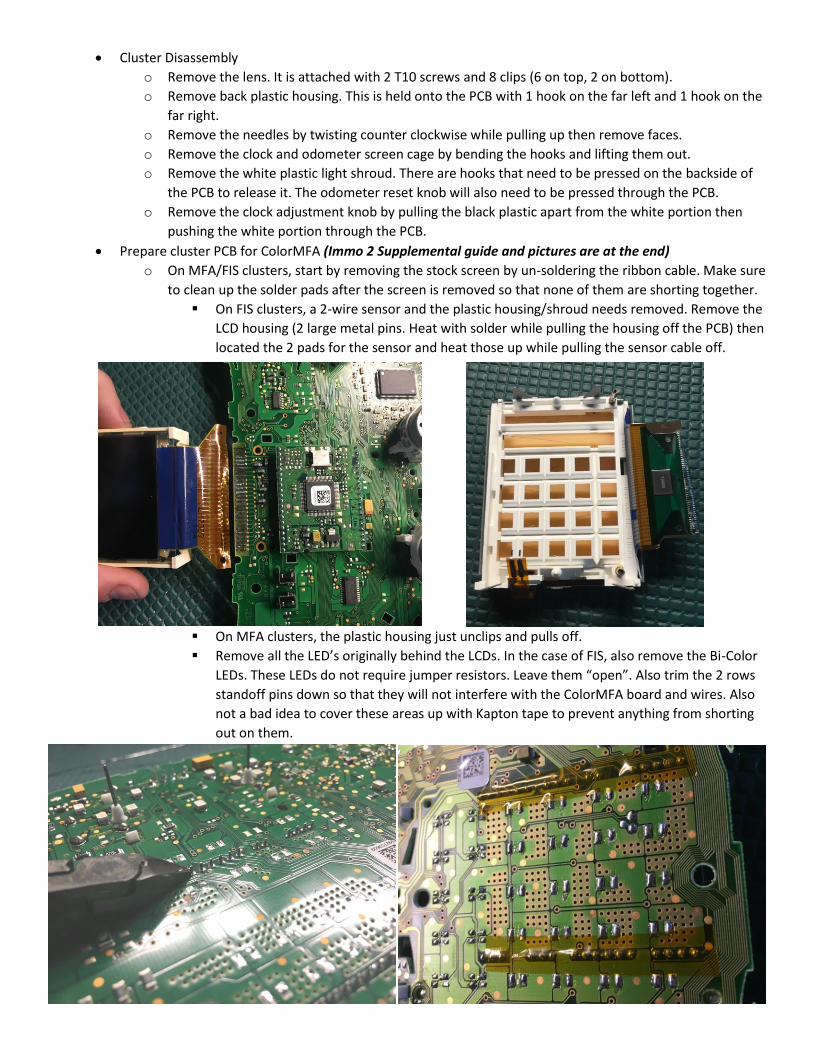
• Prepare cluster PCB for ColorMFA (Immo 2 Supplemental guide and pictures are at the end)
o On MFA/FIS clusters, start by removing the stock screen by un-soldering the ribbon cable. Make sure
to clean up the solder pads after the screen is removed so that none of them are shorting together.
▪ On FIS clusters, a 2-wire sensor and the plastic housing/shroud needs removed. Remove the
LCD housing (2 large metal pins. Heat with solder while pulling the housing off the PCB) then
located the 2 pads for the sensor and heat those up while pulling the sensor cable off.
▪ On MFA clusters, the plastic housing just unclips and pulls off.
▪ Remove all the LED’s originally behind the LCDs. In the case of FIS, also remove the Bi-Color
LEDs. These LEDs do not require jumper resistors. Leave them “open”. Also trim the 2 rows
standoff pins down so that they will not interfere with the ColorMFA board and wires. Also
not a bad idea to cover these areas up with Kapton tape to prevent anything from shorting
out on them.

▪ For both MFA and FIS, on the backside of the PCB, cut the 3 traces near the green plug for
the factory wiper stalk menu controls.
o If it is an automatic transmission LowLine cluster, remove the PRND32 screen and LED’s behind it.
o Note the orientation of the warning light LEDs. Once you note the anode and cathode of the oil
level, washer fluid, and pad wear LEDs, remove all warning LEDs and jumper them together using
the supplied SMD resistors.


• Fitting ColorMFA to cluster
o Solder the Trinput 1, 2, and 8 to their respective warning lights. Remember if you don’t have an oil
level sensor and soldered that to ignition power before, you’ll only have 2 wires to solder during this
step.
▪ If you are fitting the unit to a FIS cluster, Trinput 1 and 8 are not used and Trinput 2 goes to
the green cluster plug pin7 instead.
o Feed the 2 remaining wire bundles through the PCB. Also, remove the double-sided tape backing
and press the ColorMFA board to the cluster. The large diode at the top of the board should be
centered with the high beam LED(s). Leave about a 3mm gap between the bottom of the board
and the cluster PCB. Do not have the edges of the two be flush with one another of the screen will
sit too low and the bottom of the screen will be covered up when the lens is installed.

o Start with one bundle of wires. For these steps, we will start with the “blue connector” bundle
which has the larger gauge wire, 3 (or 4 if FIS) wires to the blue connector and the beeper wires.
Use a multimeter to identify each of the 3 larger gauge wires and solder them as shown below.
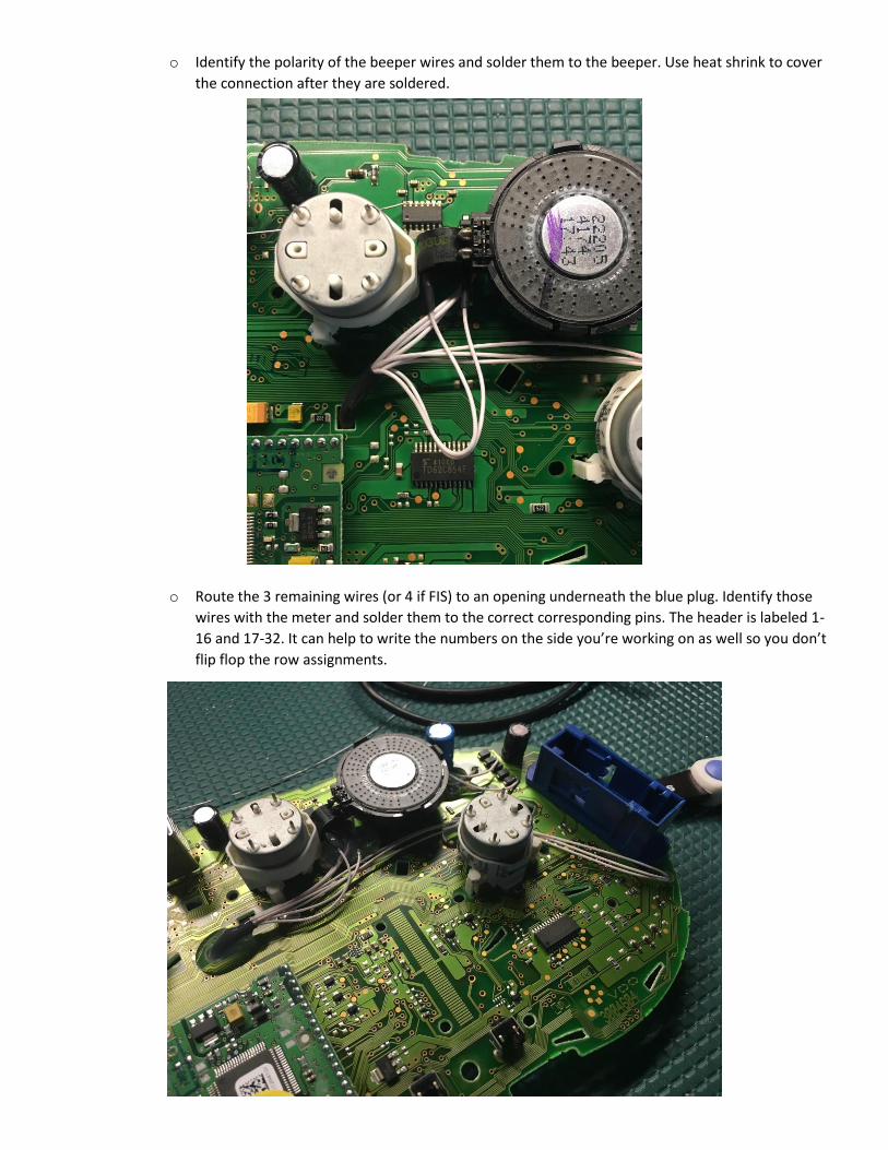
o Identify the polarity of the beeper wires and solder them to the beeper. Use heat shrink to cover
the connection after they are soldered.
o Route the 3 remaining wires (or 4 if FIS) to an opening underneath the blue plug. Identify those
wires with the meter and solder them to the correct corresponding pins. The header is labeled 1-
16 and 17-32. It can help to write the numbers on the side you’re working on as well so you don’t
flip flop the row assignments.
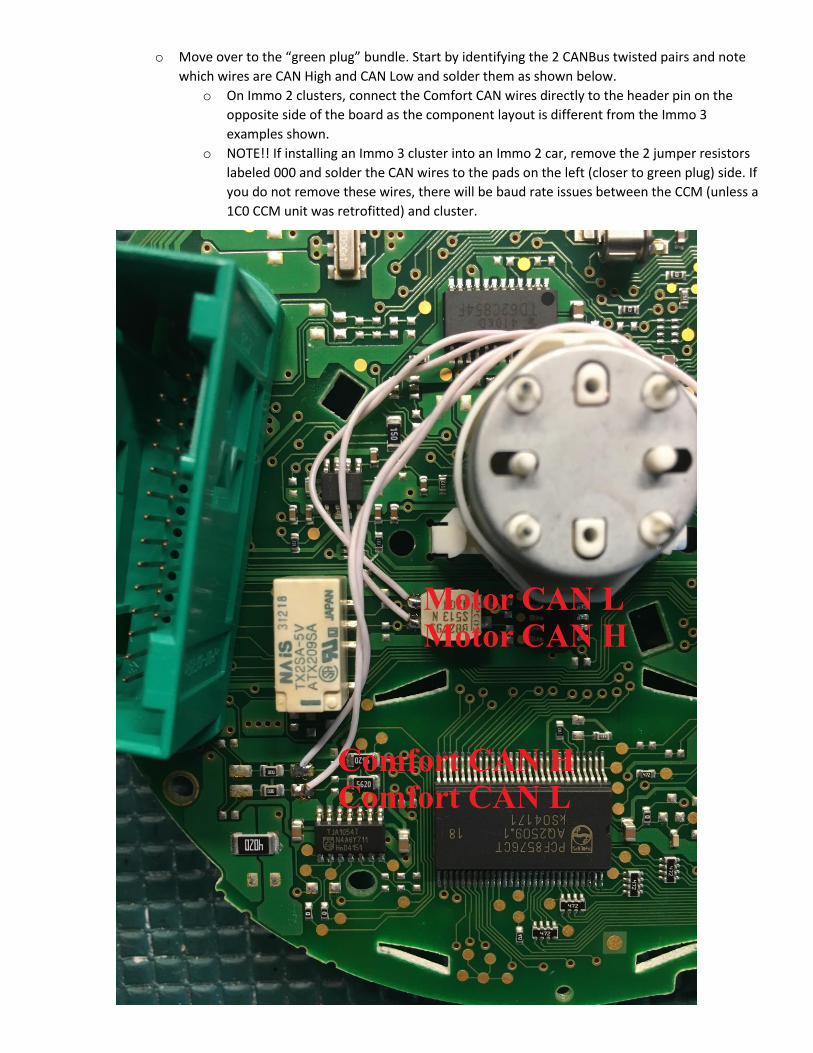
o Move over to the “green plug” bundle. Start by identifying the 2 CANBus twisted pairs and note
which wires are CAN High and CAN Low and solder them as shown below.
o On Immo 2 clusters, connect the Comfort CAN wires directly to the header pin on the
opposite side of the board as the component layout is different from the Immo 3
examples shown.
o NOTE!! If installing an Immo 3 cluster into an Immo 2 car, remove the 2 jumper resistors
labeled 000 and solder the CAN wires to the pads on the left (closer to green plug) side. If
you do not remove these wires, there will be baud rate issues between the CCM (unless a
1C0 CCM unit was retrofitted) and cluster.
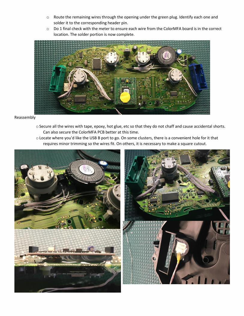
o Route the remaining wires through the opening under the green plug. Identify each one and
solder it to the corresponding header pin.
o Do 1 final check with the meter to ensure each wire from the ColorMFA board is in the correct
location. The solder portion is now complete.
Reassembly
o Secure all the wires with tape, epoxy, hot glue, etc so that they do not chaff and cause accidental shorts.
Can also secure the ColorMFA PCB better at this time.
o Locate where you’d like the USB B port to go. On some clusters, there is a convenient hole for it that
requires minor trimming so the wires fit. On others, it is necessary to make a square cutout.

o Use a rotary tool to trim an opening in the white plastic shroud to fit the ColorMFA screen. It is necessary
to cut out roughly half of the high beam icon area and flatten out the round posts on either side.
o If using a MK4 sport or B5.5 Passat lens, the alignment pin on the high beam icon must be cut off. None
sport clusters do not have this plastic icon.
o Cut the matte screen protector film to the size of the LCD and apply it to the LCD. Additionally, it’s not a
bad idea to apply a small piece of black electrical tape to the top area where the screen covers up the high
beam icon. This will prevent any LCD light bleeding through the high beam icon at night.
o Install the white plastic shrouding, clock/odometer screens and cages, reset and clock knobs.
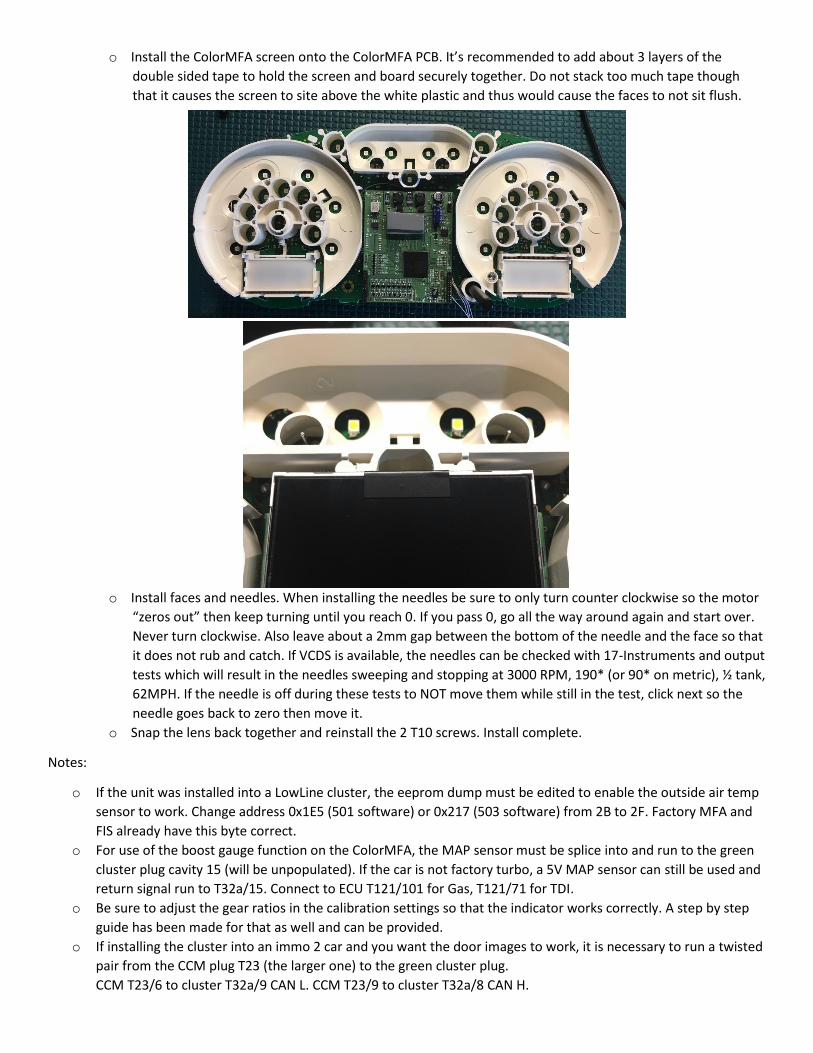
o Install the ColorMFA screen onto the ColorMFA PCB. It’s recommended to add about 3 layers of the
double sided tape to hold the screen and board securely together. Do not stack too much tape though
that it causes the screen to site above the white plastic and thus would cause the faces to not sit flush.
o Install faces and needles. When installing the needles be sure to only turn counter clockwise so the motor
“zeros out” then keep turning until you reach 0. If you pass 0, go all the way around again and start over.
Never turn clockwise. Also leave about a 2mm gap between the bottom of the needle and the face so that
it does not rub and catch. If VCDS is available, the needles can be checked with 17-Instruments and output
tests which will result in the needles sweeping and stopping at 3000 RPM, 190* (or 90* on metric), ½ tank,
62MPH. If the needle is off during these tests to NOT move them while still in the test, click next so the
needle goes back to zero then move it.
o Snap the lens back together and reinstall the 2 T10 screws. Install complete.
Notes:
o If the unit was installed into a LowLine cluster, the eeprom dump must be edited to enable the outside air temp
sensor to work. Change address 0x1E5 (501 software) or 0x217 (503 software) from 2B to 2F. Factory MFA and
FIS already have this byte correct.
o For use of the boost gauge function on the ColorMFA, the MAP sensor must be splice into and run to the green
cluster plug cavity 15 (will be unpopulated). If the car is not factory turbo, a 5V MAP sensor can still be used and
return signal run to T32a/15. Connect to ECU T121/101 for Gas, T121/71 for TDI.
o Be sure to adjust the gear ratios in the calibration settings so that the indicator works correctly. A step by step
guide has been made for that as well and can be provided.
o If installing the cluster into an immo 2 car and you want the door images to work, it is necessary to run a twisted
pair from the CCM plug T23 (the larger one) to the green cluster plug.
CCM T23/6 to cluster T32a/9 CAN L. CCM T23/9 to cluster T32a/8 CAN H.

Immo 2 VDO Supplement Guide
Immo 2 PCBs are slightly different from Immo 3 and they do not have Comfort CANBus. The pictures below will
note the differences and how to connect ColorMFA correctly into these clusters.
o On MFA/FIS, cut the factory screen control traces.
o Immo 2 Lowline and Midline clusters only have 6 warning light provisions instead of 8. The LED’s are also turned
90*. As like Immo 3, they need removed and jumpered with the supplied SMD resistors then Trinput wires
soldered according to the diagram below.
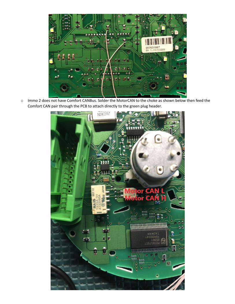
o Immo 2 does not have Comfort CANBus. Solder the MotorCAN to the choke as shown below then feed the
Comfort CAN pair through the PCB to attach directly to the green plug header.
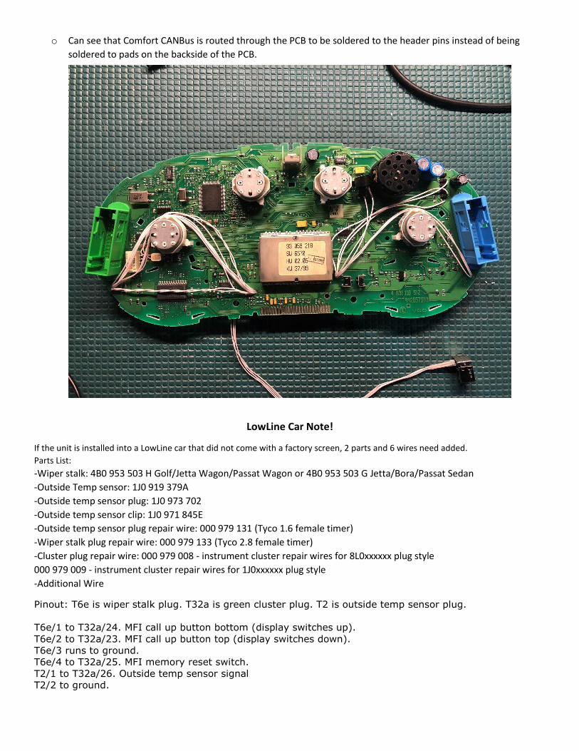
o Can see that Comfort CANBus is routed through the PCB to be soldered to the header pins instead of being
soldered to pads on the backside of the PCB.
LowLine Car Note!
If the unit is installed into a LowLine car that did not come with a factory screen, 2 parts and 6 wires need added.
Parts List:
-Wiper stalk: 4B0 953 503 H Golf/Jetta Wagon/Passat Wagon or 4B0 953 503 G Jetta/Bora/Passat Sedan
-Outside Temp sensor: 1J0 919 379A
-Outside temp sensor plug: 1J0 973 702
-Outside temp sensor clip: 1J0 971 845E
-Outside temp sensor plug repair wire: 000 979 131 (Tyco 1.6 female timer)
-Wiper stalk plug repair wire: 000 979 133 (Tyco 2.8 female timer)
-Cluster plug repair wire: 000 979 008 - instrument cluster repair wires for 8L0xxxxxx plug style
000 979 009 - instrument cluster repair wires for 1J0xxxxxx plug style
-Additional Wire
Pinout: T6e is wiper stalk plug. T32a is green cluster plug. T2 is outside temp sensor plug.
T6e/1 to T32a/24. MFI call up button bottom (display switches up).
T6e/2 to T32a/23. MFI call up button top (display switches down).
T6e/3 runs to ground.
T6e/4 to T32a/25. MFI memory reset switch.
T2/1 to T32a/26. Outside temp sensor signal
T2/2 to ground.
