vtt's observations on tar measurements
TRANSCRIPT

VTT’s observations on tar measurements
Gas Analysis 2013 Workshop
at the 21st European Biomass Conference and
ExhibitionMatti ReinikainenVTT Technical Research Centre of Finland
210/06/2013
2
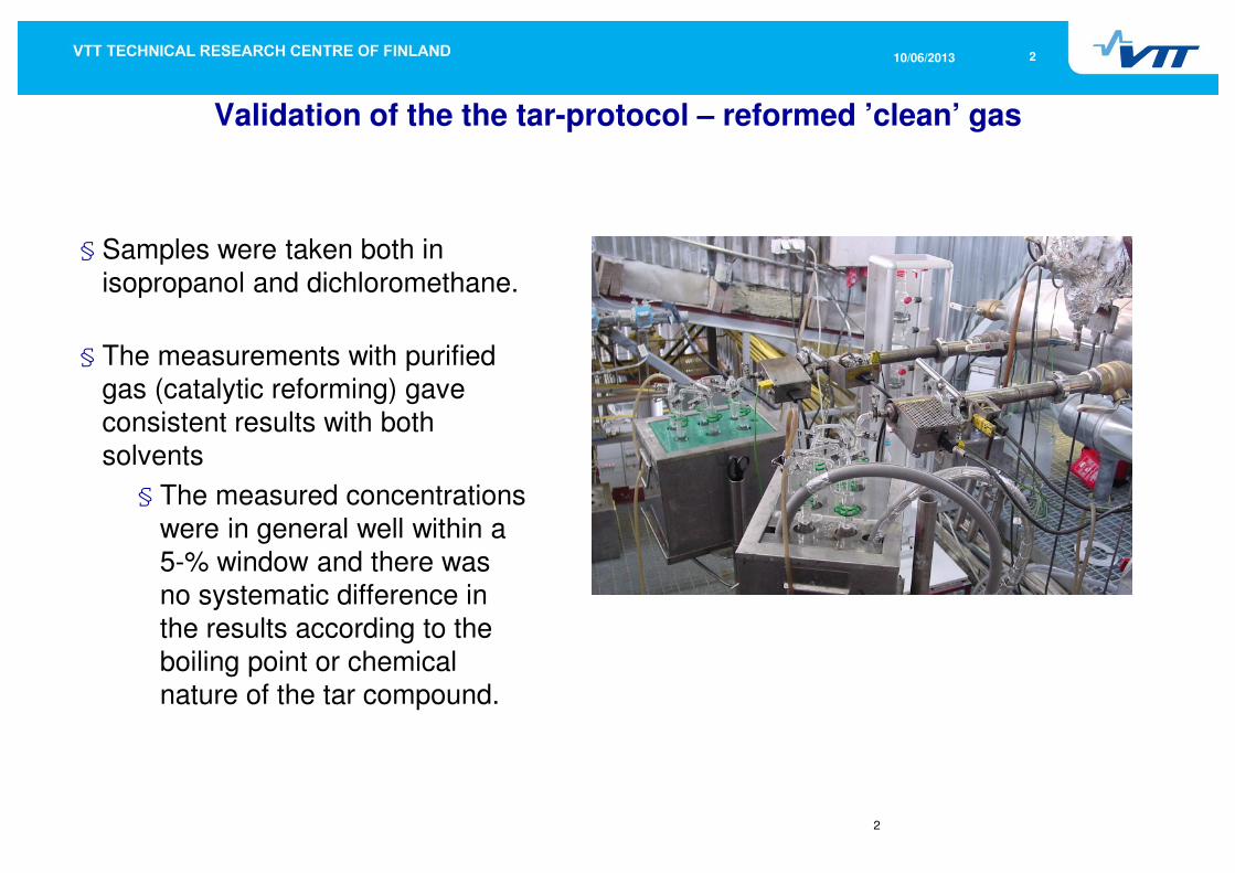
Validation of the the tar-protocol – reformed ’clean’ gas
§ Samples were taken both in
isopropanol and dichloromethane.
§ The measurements with purified gas (catalytic reforming) gave
consistent results with both
solvents
§ The measured concentrations
were in general well within a
5-% window and there was no systematic difference in
the results according to the
boiling point or chemical nature of the tar compound.
310/06/2013
3
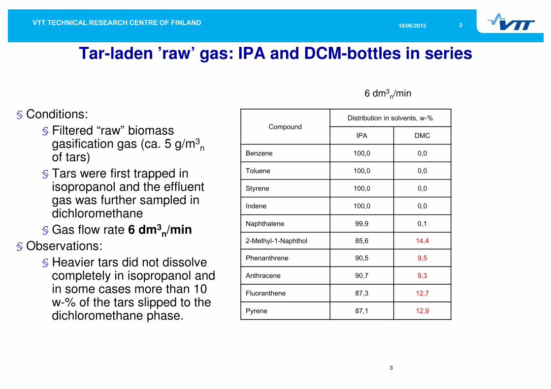
Tar-laden ’raw’ gas: IPA and DCM-bottles in series
§ Conditions:
§ Filtered “raw” biomass gasification gas (ca. 5 g/m3
n
of tars)
§ Tars were first trapped in isopropanol and the effluent gas was further sampled in dichloromethane
§ Gas flow rate 6 dm3n/min
§ Observations:
§ Heavier tars did not dissolve completely in isopropanol and in some cases more than 10 w-% of the tars slipped to the dichloromethane phase.
CompoundDistribution in solvents, w-%
IPA DMC
Benzene 100,0 0,0
Toluene 100,0 0,0
Styrene 100,0 0,0
Indene 100,0 0,0
Naphthalene 99,9 0,1
2-Methyl-1-Naphthol 85,6 14,4
Phenanthrene 90,5 9,5
Anthracene 90,7 9,3
Fluoranthene 87,3 12,7
Pyrene 87,1 12,9
6 dm3n/min
410/06/2013
4
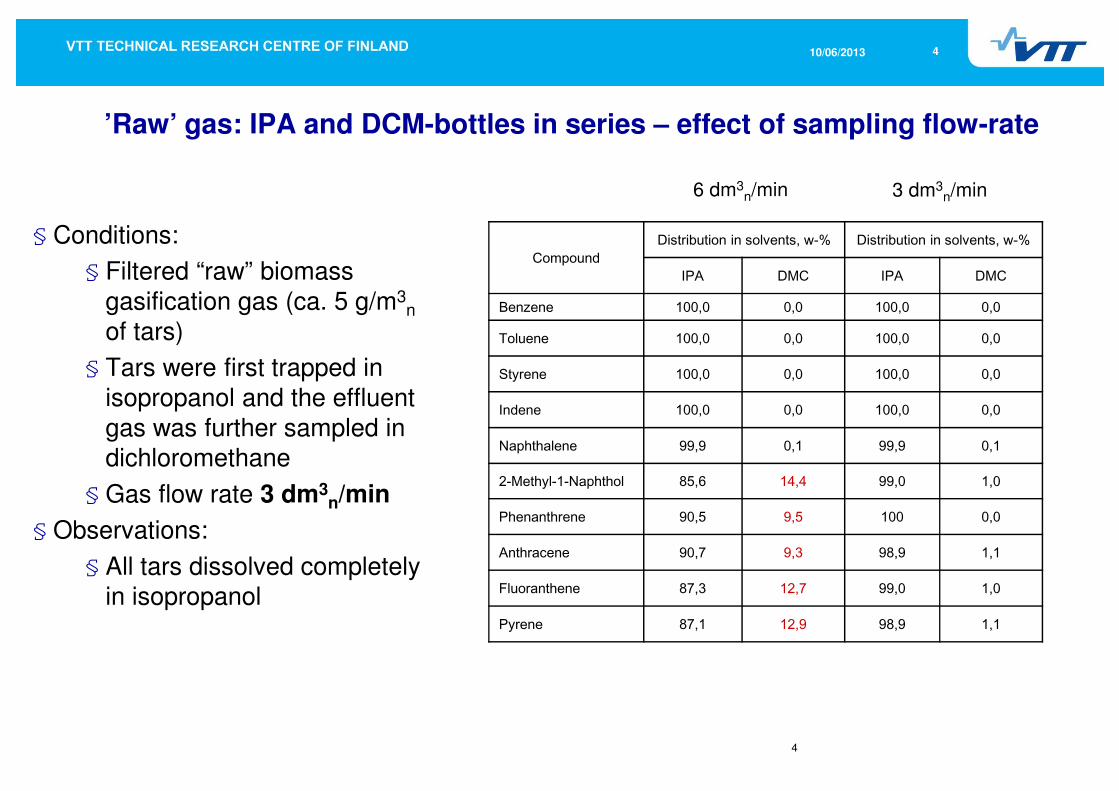
’Raw’ gas: IPA and DCM-bottles in series – effect of sampling flow-rate
§ Conditions:
§ Filtered “raw” biomass
gasification gas (ca. 5 g/m3n
of tars)
§ Tars were first trapped in
isopropanol and the effluent
gas was further sampled in dichloromethane
§ Gas flow rate 3 dm3n/min
§ Observations:
§ All tars dissolved completely in isopropanol
CompoundDistribution in solvents, w-% Distribution in solvents, w-%
IPA DMC IPA DMC
Benzene 100,0 0,0 100,0 0,0
Toluene 100,0 0,0 100,0 0,0
Styrene 100,0 0,0 100,0 0,0
Indene 100,0 0,0 100,0 0,0
Naphthalene 99,9 0,1 99,9 0,1
2-Methyl-1-Naphthol 85,6 14,4 99,0 1,0
Phenanthrene 90,5 9,5 100 0,0
Anthracene 90,7 9,3 98,9 1,1
Fluoranthene 87,3 12,7 99,0 1,0
Pyrene 87,1 12,9 98,9 1,1
6 dm3n/min 3 dm3
n/min
510/06/2013
5
"If anything can go wrong, it will” – despite VTT’s 30 year’s experience in tar sampling at least these things needed attention
§ Transfer of knowledge from experienced staff to to younger people had not beensufficient enough
§ New technicians were not properly trained
§ Technical staff is working in three shifts during campaigns
§ Exchange of experiences is limited
§ Written instructions were not always clear
§ Every technician had a slightly different way of carrying out the sampling
§ Glassware was not always cleaned well enough
§ Better instructions had to be given
§ Always use different glassware for raw and reformed gas
§ The grease (in spray cans) used for ground joints was suddenly changed
§ The flow rate during sampling of ’dirty’ gas may have been too high
§ Should more precise instructions be included in the standard ?
§ One batch of isopropanol contained remarkable amounts of toluene
§ All new batches of solvent must be analyzed
§ Mistake in the laboratory when calculating GC-results
610/06/2013
6
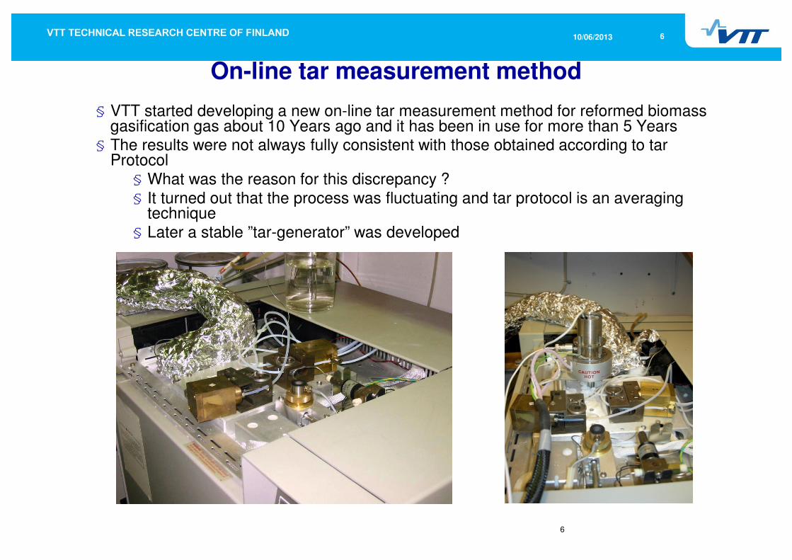
On-line tar measurement method
§ VTT started developing a new on-line tar measurement method for reformed biomassgasification gas about 10 Years ago and it has been in use for more than 5 Years
§ The results were not always fully consistent with those obtained according to tarProtocol
§ What was the reason for this discrepancy ?§ It turned out that the process was fluctuating and tar protocol is an averaging
technique§ Later a stable ”tar-generator” was developed
710/06/2013
7
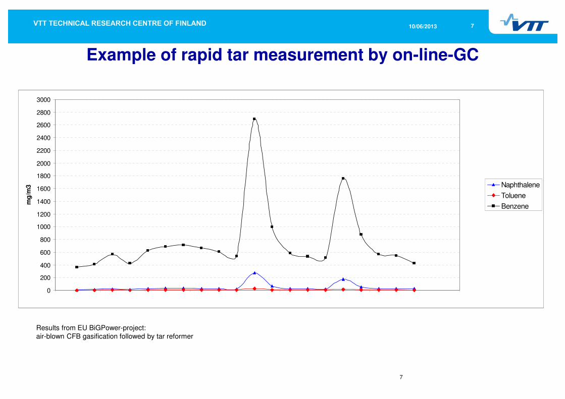
Example of rapid tar measurement by on-line-GC
0
200
400
600
800
1000
1200
1400
1600
1800
2000
2200
2400
2600
2800
3000
26.8.2008 20:24 26.8.2008 21:36 26.8.2008 22:48 27.8.2008 0:00 27.8.2008 1:12 27.8.2008 2:24 27.8.2008 3:36 27.8.2008 4:48 27.8.2008 6:00 27.8.2008 7:12
mg
/m3 Naphthalene
Toluene
Benzene
Results from EU BiGPower-project:
air-blown CFB gasification followed by tar reformer
810/06/2013
8
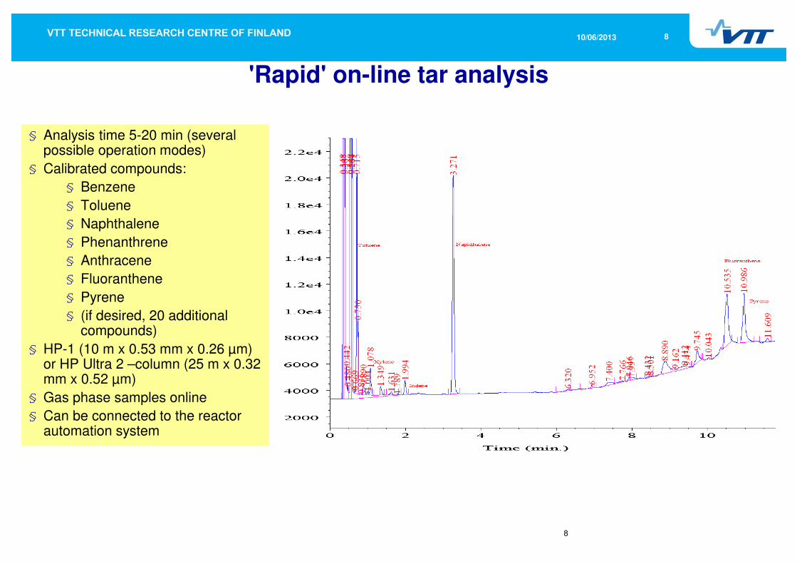
'Rapid' on-line tar analysis
§ Analysis time 5-20 min (several possible operation modes)
§ Calibrated compounds:
§ Benzene
§ Toluene
§ Naphthalene
§ Phenanthrene
§ Anthracene
§ Fluoranthene
§ Pyrene
§ (if desired, 20 additional compounds)
§ HP-1 (10 m x 0.53 mm x 0.26 µm) or HP Ultra 2 –column (25 m x 0.32 mm x 0.52 µm)
§ Gas phase samples online
§ Can be connected to the reactor automation system
910/06/2013
9
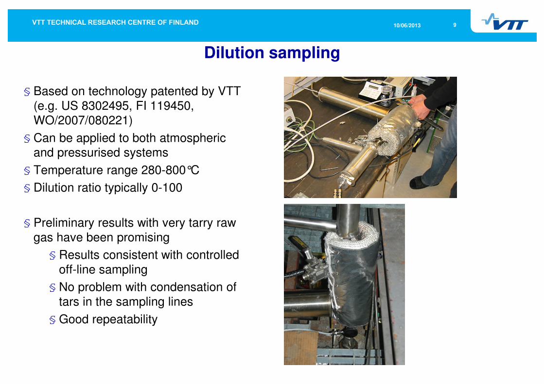
Dilution sampling
§ Based on technology patented by VTT
(e.g. US 8302495, FI 119450, WO/2007/080221)
§ Can be applied to both atmosphericand pressurised systems
§ Temperature range 280-800°C
§ Dilution ratio typically 0-100
§ Preliminary results with very tarry raw
gas have been promising
§ Results consistent with controlled
off-line sampling
§ No problem with condensation of
tars in the sampling lines
§ Good repeatability

1010/06/2013
Dilution sampling probe with control unit
1110/06/2013
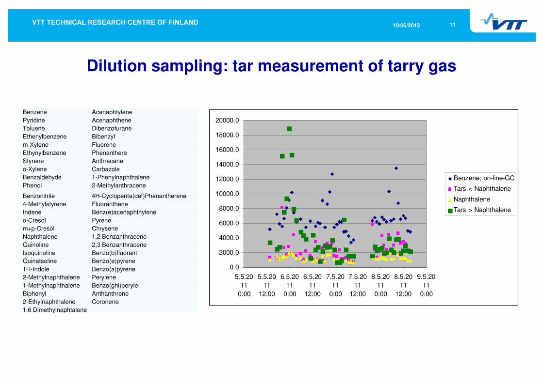
Dilution sampling: tar measurement of tarry gas
0.0
2000.0
4000.0
6000.0
8000.0
10000.0
12000.0
14000.0
16000.0
18000.0
20000.0
5.5.20
11
0:00
5.5.20
11
12:00
6.5.20
11
0:00
6.5.20
11
12:00
7.5.20
11
0:00
7.5.20
11
12:00
8.5.20
11
0:00
8.5.20
11
12:00
9.5.20
11
0:00
Benzene; on-line-GC
Tars < Naphthalene
Naphthalene
Tars > Naphthalene
Benzene Acenaphtylene
Pyridine Acenaphthene
Toluene Dibenzofurane
Ethenylbenzene Bibenzyl
m-Xylene Fluorene
Ethynylbenzene Phenanthere
Styrene Anthracene
o-Xylene Carbazole
Benzaldehyde 1-Phenylnaphthalene
Phenol 2-Methylanthracene
Benzonitrile 4H-Cyclopenta(def)Phenantherene
4-Methylstyrene Fluoranthene
Indene Benz(e)acenaphthylene
o-Cresol Pyrene
m+p-Cresol Chrysene
Naphthalene 1,2 Benzanthracene
Quinoline 2,3 Benzanthracene
Isoquinoline Benzo(b)fluorant
Quinatsoline Benzo(e)pyrene
1H-Indole Benzo(a)pyrene
2-Methylnaphthalene Perylene
1-Methylnaphthalene Benzo(ghi)peryle
Biphenyl Anthanthrene
2-Ethylnaphthalene Coronene
1.6 Dimethylnaphtalene

1210/06/2013
Comparison of tar analyses by on-line (dilution) and of-line methods
mg/m3n On-line Off-line
Benzene 10101.1 12724.7
Toluene 689.5 689.5
m-Xylene 41.0 32.5
Styrene 128.0 144.5
o-Xylene 0.0 0.0
Phenol 38.0 40.0
Indene 395.9 374.0
Naphthalene 3792.4 3024.7
2-Methylnaphthalene 58.0 66.9
1-Methylnaphthalene 46.5 36.3
Biphenyl 86.3 68.4
1.6 Dimethylnaphtalene 0.0 2.7
Acenaphtylene 468.7 490.6
Dibenzofurane 65.0 71.5
Fluorene 174.8 174.6
Phenanthere 638.0 602.4
Anthracene 189.4 157.3
4H-cyclopental(def)Phenanthrene 79.8 52.2
Fluoranthene 501.2 252.2
Pyrene 391.0 229.6
mg/m3n On-line Off-line
Benzene 6630,2 7380,1
Pyridine 45,1 83,8
Toluene 866,6 674,4
m-Xylene 82,4 30,8
Styrene 238,8 196,6
Phenol 927,9 702,1
4-Methylstyrene 146,5 114,5
Indene 233,9 252,7
Naphthalene 1449,9 1702,2
2-Methylnaphthalene 101,9 72,3
1-Methylnaphthalene 55,5 38,7
Biphenyl 93,5 85,5
1.6 Dimethylnaphtalene 31,6 0,0
Acenaphtylene 334,8 339,7
Acenaphthene 18,0 20,6
Dibenzofurane 163,2 175,4
Fluorene 59,9 52,9
Phenanthere 832,5 291,6
Anthracene 178,4 56,2
Fluoranthene 814,0 131,1
Pyrene 717,8 78,7
Chrysene 243,1 14,8
a) Laboratory gasifier b) Commercial gasifier

1310/06/2013
Dilution sampling: tar and particle measurement from highly tar-laden
gas

1410/06/2013
Pressurised hot gas filtration test rig ALMA
§ Simulated gasification gas including soot and tars is fed to a filter unit.
§ Pressures up to 5 bar(g), filtration temperatures up to 850 °C
CH4 O2 N2
DUST REMOVAL
TO GAS ANALYZER
TO GAS INCINERATION
TAR SAMPLING
Pd
T
COOLER
CARRIERGAS N2
FC
FC
AIR
N2
SIMULATED
GASIFICATION
GAS
H2O FC
BOILER
DUST FEED
FC
TAR FEED
T
PULSE TANK
Pd
TO GAS ANALYZER
TAR SAMPLING
CO,CO2, H2, CH4,H2O, tar
H2OFC
FC FC
FCC2H4

1510/06/2013
Observations on tar measurements
§ Under carefully controlled conditions, the Tar Protocol seems to be a reliable method for the analysis of tars when the concentration of heavy tars is fairly low
§ However, there are several possible sources of error and care must betaken to avoid them
§ As a typical off-line method the Protocol is fairly labour-intensive and time-consuming. A fast on-line tar analysis method for ‘clean gases’ overcomes this problem. With this method the concentration of typical light tar components can be analyzed in about 15 minutes
§ When the gas contains large amounts of heavy tars the Tar protocol may underestimate their amount (3-10 fold!). With fairly clean gases the results of on-line measurement have been in good agreement with the results from controlled off-line analysis off the corresponding samples. On-line analysis has proved to be especially useful in transient conditions where the gas composition changes quickly
§ Combined with dilution sampling, on-line method can be applied alsoto ’dirty’ gases
1610/06/2013
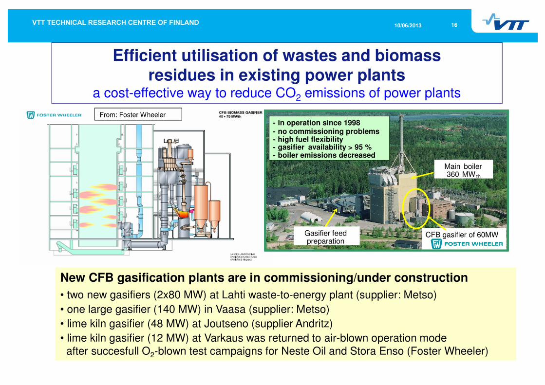
Efficient utilisation of wastes and biomassresidues in existing power plants
a cost-effective way to reduce CO2 emissions of power plants
CFB gasifier of 60MW
Main boiler360 MW th
Gasifier feed preparation
- in operation since 1998- no commissioning problems- 50 000 operating hours- gasifier availability > 95 %- boiler emissions decreased- payback time ca. 8 years
CFB gasifier of 60MW
Main boiler360 MW th
Gasifier feed preparation
- in operation since 1998- no commissioning problems- high fuel flexibility- gasifier availability > 95 %- boiler emissions decreased-
From: Foster Wheeler
New CFB gasification plants are in commissioning/under construction
• two new gasifiers (2x80 MW) at Lahti waste-to-energy plant (supplier: Metso)
• one large gasifier (140 MW) in Vaasa (supplier: Metso)
• lime kiln gasifier (48 MW) at Joutseno (supplier Andritz)
• lime kiln gasifier (12 MW) at Varkaus was returned to air-blown operation modeafter succesfull O2-blown test campaigns for Neste Oil and Stora Enso (Foster Wheeler)

1710/06/2013
From: Kari Salo, Andritz, 2011

1810/06/2013
2G Biofuels Project and New RES-Infra
§VTT will move it’s Gasification and Pyrolysis test equipment from Otaniemi to an industrial area in Kivenlahti, Espoo
§New pilot facilities will also be constructed
§Start-up at new site in Q3-Q4/2014, testing is continued in Otaniemiusing present facilities until end 2013
2G Biofuels R&D&Piloting poject7.2 M€: 2012-14, 2nd phase planned for 2015-16
VTT RES-InfraInvestmentFunding forequipment
1910/06/2013
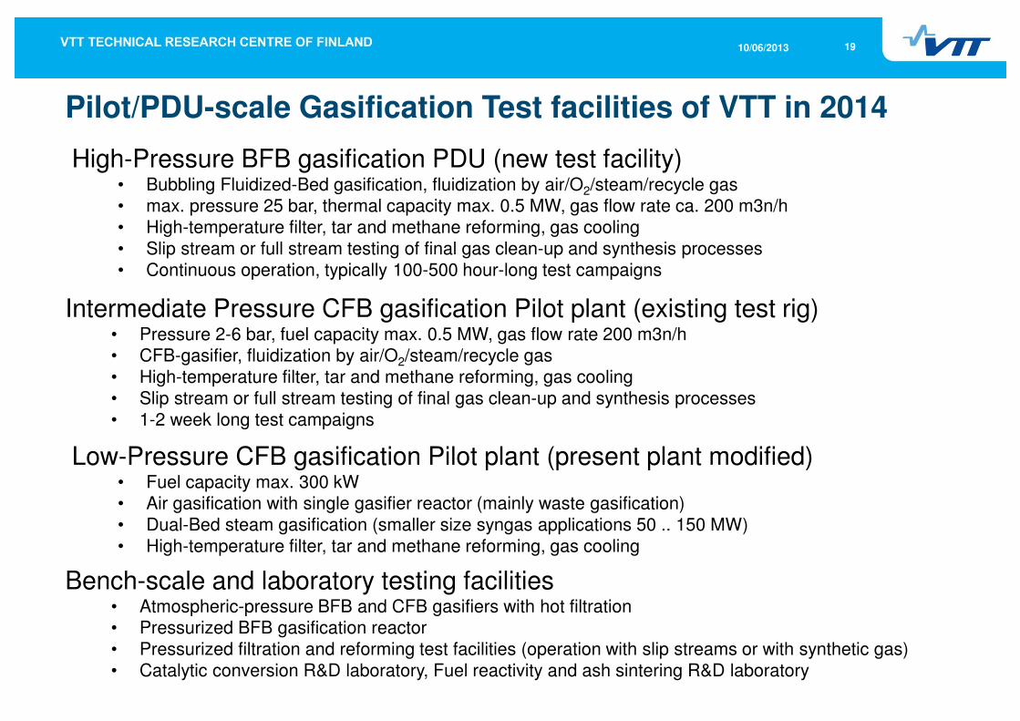
Pilot/PDU-scale Gasification Test facilities of VTT in 2014
Intermediate Pressure CFB gasification Pilot plant (existing test rig)• Pressure 2-6 bar, fuel capacity max. 0.5 MW, gas flow rate 200 m3n/h• CFB-gasifier, fluidization by air/O2/steam/recycle gas
• High-temperature filter, tar and methane reforming, gas cooling
• Slip stream or full stream testing of final gas clean-up and synthesis processes
• 1-2 week long test campaigns
High-Pressure BFB gasification PDU (new test facility)• Bubbling Fluidized-Bed gasification, fluidization by air/O2/steam/recycle gas• max. pressure 25 bar, thermal capacity max. 0.5 MW, gas flow rate ca. 200 m3n/h
• High-temperature filter, tar and methane reforming, gas cooling
• Slip stream or full stream testing of final gas clean-up and synthesis processes
• Continuous operation, typically 100-500 hour-long test campaigns
Low-Pressure CFB gasification Pilot plant (present plant modified)• Fuel capacity max. 300 kW• Air gasification with single gasifier reactor (mainly waste gasification)
• Dual-Bed steam gasification (smaller size syngas applications 50 .. 150 MW)
• High-temperature filter, tar and methane reforming, gas cooling
Bench-scale and laboratory testing facilities• Atmospheric-pressure BFB and CFB gasifiers with hot filtration• Pressurized BFB gasification reactor
• Pressurized filtration and reforming test facilities (operation with slip streams or with synthetic gas)
• Catalytic conversion R&D laboratory, Fuel reactivity and ash sintering R&D laboratory
2010/06/2013
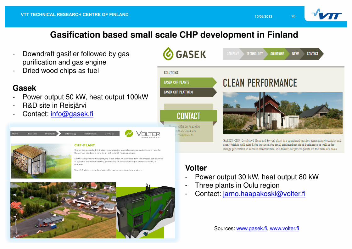
- Downdraft gasifier followed by gas purification and gas engine
- Dried wood chips as fuel
Gasek- Power output 50 kW, heat output 100kW- R&D site in Reisjärvi- Contact: [email protected]
Volter- Power output 30 kW, heat output 80 kW- Three plants in Oulu region- Contact: [email protected]
Gasification based small scale CHP development in Finland
Sources: www.gasek.fi, www.volter.fi

2110/06/2013
Gasification and filtration experiments with AFB60
§ The main focus of experiments:
§ Performance of the filter at temperatures550-800 °C (filter blinding issues etc.)
§ Alkali metal retention on the filter: alkalimetal measurements after filter
§ Bed sintering
§ Filter ashes will be analysed in a moredetail
§ Experiments will be carried out with an
atmospheric pressure, bench-scalegasification test rig AFB60:
§ Bubbling fluidised-bed gasifier
(bed i.d. 63 mm)
§ Hot gas filter equipped with 2-3 rigidceramic filter candles: SiC, o.d. 60 mm