véronique beauvois, ir. 2018-2019
TRANSCRIPT

Copyright © 2018 Véronique Beauvois, ULg
Coupling modes
Véronique Beauvois, Ir. 2018-2019
1

Copyright © 2018 Véronique Beauvois, ULg
General problem in EMC = a trilogy
Source (disturbing)
Victim (disturbed)
• lightning • electrostatic discharges • motors, converters • etc.
• receivers • sensors • amplifiers • µC • etc.
propagation Coupling modes
• conducted (I / U) • radiated (cables, slot, shielding defect,…)
Parameters • Amplitude • Spectrum
2

Copyright © 2018 Véronique Beauvois, ULg
General solution in EMC = a trilogy
Source (disturbing)
Victim (disturbed) propagation
Coupling mode
To act on the source (not always possible) To act on the victim
(increasing immunity – reducing susceptibility)
To reduce the efficiency of the coupling mode
= frequently only solution
or different combined solutions
Remark : reciprocity (to improve emission frequently improve also immunity)
3

Copyright © 2018 Véronique Beauvois, ULg
1st step: to identify the disturbing elements
Protections
Ä for inter-system Ä for intra-system
= source & victim inside the same system
4

Copyright © 2018 Véronique Beauvois, ULg
Power supply
Envelop
1
2
3 Control/ Communication
To identify the disturbing elements, the coupling paths, …
5

Copyright © 2018 Véronique Beauvois, ULg
To add elements/components to reduce some effects
Power supply
Envelop
1
2
3 Control/ Communication
6

Copyright © 2018 Véronique Beauvois, ULg © ABB Drives
7

Copyright © 2018 Véronique Beauvois, ULg
The coupling modes between source and victim could be classified according to: • Common mode • Differential mode
Differential mode (DM) (or symetrical) : current is on one conductor in one direction and in phase opposition on the second conductor (e.g. power supply, RS-485, CAN, USB).
Coupling modes
8

Copyright © 2018 Véronique Beauvois, ULg
Common Mode (CM) (or asymetrical or longitudinal) : current on both conductors in the same direction.
The EM disturbances are weakly coupled in DM as conductors are nearby. On the other hand, in CM, current could be induced by an external field.
Coupling modes
9

Copyright © 2018 Véronique Beauvois, ULg
How to measure CM and DM? With a current clamp
CM
DM
Coupling modes
10

Copyright © 2018 Véronique Beauvois, ULg
Conversion between DM and CM Related to the parasitic impedances of different values
Origin? When 2 conductors have a different impedance regarding earth (parasitic capacitors) If ZA=ZB, there is no voltage accross RL due to ICM If ZA≠ZB, Vcharge(CM)= ICM.(ZA-ZB)
Coupling modes
11

Copyright © 2018 Véronique Beauvois, ULg
A. Common impedance coupling (conducted coupling) = common conductor
Solutions: • to decrease Z (coupling) • to decrease ip (source)
Considering a conductor AB, impedance Z(f) (≠0) :
ip
Coupling modes
12

Copyright © 2018 Véronique Beauvois, ULg
A. Common impedance coupling (conducted coupling) = common conductor
Coupling modes
13

Copyright © 2018 Véronique Beauvois, ULg
A. Common impedance coupling (conducted coupling) = common conductor
Coupling modes
14

Copyright © 2018 Véronique Beauvois, ULg
B. Inductive Coupling
The circulation of a current in a conductor creates a magnetic field, which could couple with a nearby circuit, and induced a voltage. Solutions: • source: to decrease dB/dt • victim: to decrease S or modify orientation (n and B perpendicular, B // loop) • coupling: to increase distance or add a magnetic screen
Coupling modes
15

Copyright © 2018 Véronique Beauvois, ULg
External disturbance
To reduce S loop
Coupling modes
B. Inductive Coupling
16

Copyright © 2018 Véronique Beauvois, ULg
Inductive diaphony
Δis > B > ip V=L2di2/dt+Mdi1/dt
Coupling modes
B. Inductive Coupling
17

Copyright © 2018 Véronique Beauvois, ULg
VN = - M x dIL/dt
Coupling modes
B. Inductive Coupling
18

Copyright © 2018 Véronique Beauvois, ULg
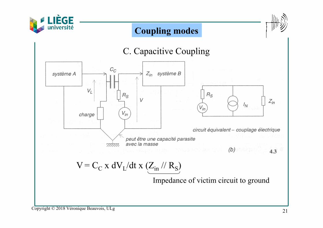
C. Capacitive Coupling
dU/dt > E electric field could couple with a nearby conductor and generate a voltage Solutions: • source: to reduce dU/dt • coupling: to increase distance
Coupling modes
19

Copyright © 2018 Véronique Beauvois, ULg
Capacitive diaphony
C. Capacitive Coupling
Coupling modes
20
Copyright © 2018 Véronique Beauvois, ULg
V = CC x dVL/dt x (Zin // RS) Impedance of victim circuit to ground
C. Capacitive Coupling
Coupling modes
21
Copyright © 2018 Véronique Beauvois, ULg
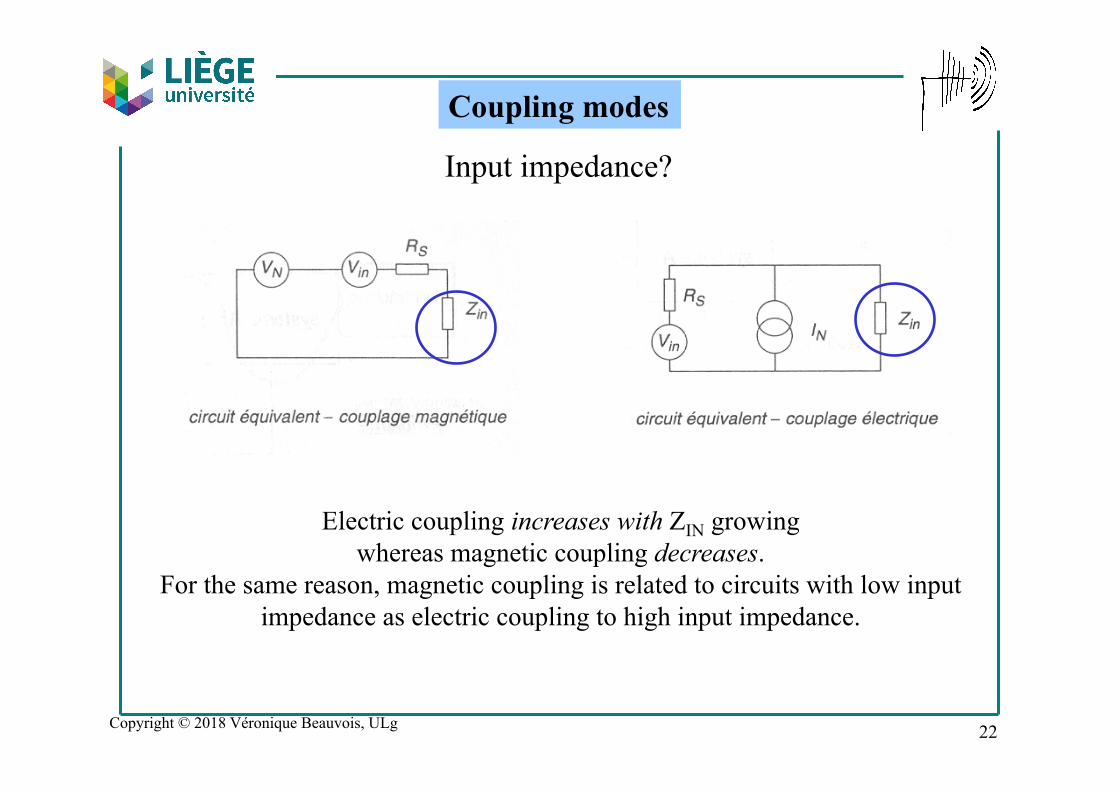
Input impedance?
Electric coupling increases with ZIN growing whereas magnetic coupling decreases.
For the same reason, magnetic coupling is related to circuits with low input impedance as electric coupling to high input impedance.
Coupling modes
22

Copyright © 2018 Véronique Beauvois, ULg
Relationship distance - M and C
Coupling modes
23

Copyright © 2018 Véronique Beauvois, ULg
D. Radiated Coupling
• H-field (field to loop) • E-field (field to conductor)
Coupling modes
24

Copyright © 2018 Véronique Beauvois, ULg
D. Radiated Coupling 1. Electromagnetic field of short electric dipole
Conductor length l with a current Io
l <<< λ of the field
So Io is constant on l
Coupling modes
25

Copyright © 2018 Véronique Beauvois, ULg
1. Electromagnetic field of short electric dipole
Electromagnetic fields (in spherical coordinates) is evaluated at an observation point P at a distance r from the origin:
26

Copyright © 2018 Véronique Beauvois, ULg
We have to consider 3 cases: - r >> λ/(2π) or kr >> 1
far-field - r << λ/(2π) or kr << 1
near-field - r ≈ λ/(2π) or kr ≈ 1
intermediate zone
1. Electromagnetic field of short electric dipole
27

Copyright © 2018 Véronique Beauvois, ULg
Far-field For θ=0°, no electromagnetic wave, consider θ=90° (maximum of radiation):
Caracteristic Impedance
1. Electromagnetic field of short electric dipole
28

Copyright © 2018 Véronique Beauvois, ULg
Near-field
1. Electromagnetic field of short electric dipole
Caracteristic Impedance
29

Copyright © 2018 Véronique Beauvois, ULg
1. Electromagnetic field of short electric dipole
30

Copyright © 2018 Véronique Beauvois, ULg
Consider a loop with Io
Coupling modes
D. Radiated Coupling 2. Electromagnetic field of magnetic dipole
31

Copyright © 2018 Véronique Beauvois, ULg
2. Electromagnetic field of magnetic dipole
Electromagnetic fields (in spherical coordinates):
32

Copyright © 2018 Véronique Beauvois, ULg
Far-field (r >> λ/(2π) ) For θ=90°:
2. Electromagnetic field of magnetic dipole
Caracteristic Impedance
33

Copyright © 2018 Véronique Beauvois, ULg
Near-field (r << λ/(2π) )
2. Electromagnetic field of magnetic dipole
Caracteristic Impedance
34

Copyright © 2018 Véronique Beauvois, ULg
2. Electromagnetic field of magnetic dipole
35
Copyright © 2018 Véronique Beauvois, ULg
D. Radiated Coupling Wave impedance of electromagnetic field
E/H is called wave impedance. It is an important parameter as it determines the coupling efficiency ot this wave with a structure, and the efficiency of a shielding structure. In far-field (r>>λ/2π), plane wave, E and H are decreasing in the same proportion with distance. Z is a constant and in air 377Ω. In near-field (r<<λ/2π), Z is determined by the characteristics of the source.
36

Copyright © 2018 Véronique Beauvois, ULg
D. Radiated Coupling
37

Copyright © 2018 Véronique Beauvois, ULg
D. Radiated Coupling Far-field – near-field
Rayleigh criterion This criterion is related to the radiating diagram of an antenna, too large to be considered as a ponctual source. To consider a far-field condition as acceptable, it is needed that the phase shift of the components of the radiated field from the 2 ends of the antenna is small, regarding λ. We have a criterion related to λ and maximum dimension D of antenna:
d >>> 2D²/λ
38

Copyright © 2018 Véronique Beauvois, ULg
Disturbances and Power Quality
Véronique Beauvois, Ir. 2018-2019
39

Copyright © 2018 Véronique Beauvois, ULg
Definition of a disturbance
An electromagnetic phenomenon susceptible to degrade the performances of an apparatus or system.
© Groupe Schneider
40

Copyright © 2018 Véronique Beauvois, ULg
Types of disturbances - Classification
• frequency: L.F. / H.F. • conducted / radiated • narrowband / broadband • duration (t): permanent, repetitive, transient, random • common mode/differential mode
41

Copyright © 2018 Véronique Beauvois, ULg
Frequency: L.F. / H.F.
• 0≤f ≤…1 MHz • conducted • f > 30MHz
• radiated
Types of disturbances - Classification
42

Copyright © 2018 Véronique Beauvois, ULg
Conducted Voltage/current
Radiated Electric/Magnetic fields
Types of disturbances - Classification
43

Copyright © 2018 Véronique Beauvois, ULg
Narrowband (disturbance bandwidth < receiver’s one) Broadband (disturbance bandwidth > receiver’s one)
Types of disturbances - Classification
44

Copyright © 2018 Véronique Beauvois, ULg
Common Mode – Differential Mode
Types of disturbances - Classification
45

Copyright © 2018 Véronique Beauvois, ULg
L.F. & conducted >> Power Quality 3-phase systems
Types of disturbances
Parameters? • frequency (50 Hz) • amplitude (V) • waveshape (sinusoidal) • symetry (phase shift 120°)
46

Copyright © 2018 Véronique Beauvois, ULg 47
1. Frequency – Deviation
Frequency variations are very small (less than 1 %) in the European network (mesh). Consequently, very few problems for electronic equipement. In a small isolated network (e.g. island or emergency power system) , the situation is different. Some process need a very precise control of speed and frequency variation could disturb.
Types of disturbances

Copyright © 2018 Véronique Beauvois, ULg 48
2. Amplitude 2.1 Voltage dips and short interruptions Voltage dips could be related to short-circuit in the network or at the customer premises (defaults, atmospheric problems, …). In this case only drop of voltages more than 10 % are considered (otherwise they are voltage fluctuations). Definition of voltage dip [EN 50160] : quick reduction of power supply at a value between 90 and 1 % of the nominal voltage, followed by a recovering very soon. Duration from 10 ms to 1 min., by definition. Short interruptions [EN 50160] : reduction of power supply under 1 % of the nominal voltage. Short : less than 3 minutes. Consequences : some equipment could stop, if the depth and duration are over certain limits (according to the sensitivity of the load).
Types of disturbances
Uref
ΔU
Δt
Voltage dip Short interruption
Uref-10%
U(t)
Urms

Copyright © 2018 Véronique Beauvois, ULg 49
2. Amplitude 2.2 Voltage fluctuations / Flicker In some installations, quick variations of power (produced or consumed) could be observed (welding, wind turbines, arc furnaces, air conditioning, …). This could lead to voltage variations. Flicker [EN 50160] : visible change in brightness of a lamp due to rapid fluctuations in the voltage of the power supply. The voltage drop is generated over the source impedance of the grid by the changing load current of an equipment (frequent starting of an elevator motor, air conditioning systems, arc furnaces, welding machines, …). Effects in the band 0.5-25Hz. Major consequences on lamps. Standards EN 61000-3-3 (I < 16A) EN 61000-3-11 (16A < I < 75A)
Types of disturbances
Copyright © 2018 Véronique Beauvois, ULg 50
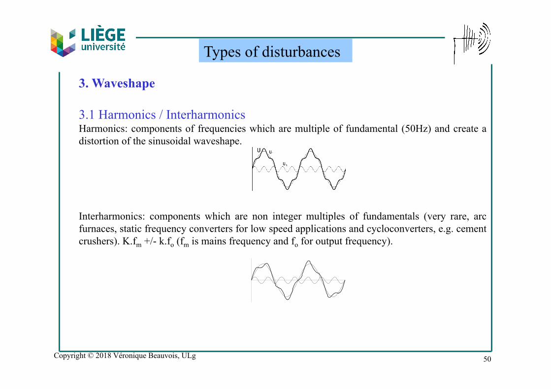
3. Waveshape 3.1 Harmonics / Interharmonics Harmonics: components of frequencies which are multiple of fundamental (50Hz) and create a distortion of the sinusoidal waveshape. Interharmonics: components which are non integer multiples of fundamentals (very rare, arc furnaces, static frequency converters for low speed applications and cycloconverters, e.g. cement crushers). K.fm +/- k.fo (fm is mains frequency and fo for output frequency).
Types of disturbances

Copyright © 2018 Véronique Beauvois, ULg
Harmonics
We have seen that a periodic signal could be represented by a sum of sinus with different amplitudes and phases, with frequency multiple integer of fundamental (frequency f). Harmonics.
51

Copyright © 2018 Véronique Beauvois, ULg
Origin? All non linear loads are associated with a non sinusoidal current
and generates harmonics
Harmonics
Sources? inverters, choppers, dc-dc converters
• rectifiers • speed controllers
• frequency converters • dimmers • lighting
• Induction heating systems • Saturated magnetic circuits
52

Copyright © 2018 Véronique Beauvois, ULg
Consequences?
Harmonics
Heating (motors, transformers, cables, …)
Losses (transformers) Saturation (transformers)
Additional torque components (motors) Resonance (Q compensation capacitors)
Homopolar components (H3) Defaults (power electronics, IT, relays, controlers, …)
…
53

Copyright © 2018 Véronique Beauvois, ULg 54
3. Waveshape 3.2 Transient Overvoltages: related to the release of low voltage apparatus, inductive loads, capacitor banks start (Q compensation) and fuse fusion. Sinusoidal damped overvoltages: some actions on the medium voltage network as a breaker opening or closing, switches disconnection, … may cause a voltage variation which excites the line with a very short pulse with a short rise time. The consequence is a damped sinus.
Types of disturbances

Copyright © 2018 Véronique Beauvois, ULg 55
3. Waveshape 3.2 Transient Burst
Types of disturbances
0…200MHz…

Copyright © 2018 Véronique Beauvois, ULg 56
3. Waveshape 3.2 Transient Surge
Types of disturbances
0…100MHz…
4kV Normalized waveshape Voltage 1,2/50µs Current 8/20µs

Copyright © 2018 Véronique Beauvois, ULg 57
4. Symmetry / Unbalance Dissymmetry in the network are very small. The main problem is the one-phase loading in a 3-phase network, and the repartition of those loads. Consequences: additional heating and flickering problems.
Types of disturbances

Copyright © 2018 Véronique Beauvois, ULg 58
Types of disturbances
DEFINITION OF POWER QUALITY (PQ)Power Quality = Voltage Continuity + Voltage Quality
Voltage Quality• frequency - deviations• magnitude - deviations
- dips & short interruptions- flicker
• waveform - (inter)harmonics• symmetry - unbalance
Voltage Continuity(Reliability of Supply)- long interruptions
Copyright © 2018 Véronique Beauvois, ULg
Examples
Véronique Beauvois, Ir. 2018-2019
59
Copyright © 2018 Véronique Beauvois, ULg 60
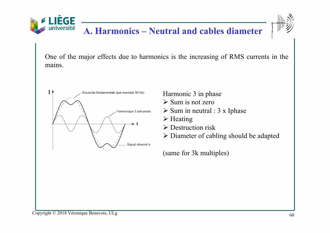
A. Harmonics – Neutral and cables diameter
Harmonic 3 in phase Ø Sum is not zero Ø Sum in neutral : 3 x Iphase Ø Heating Ø Destruction risk Ø Diameter of cabling should be adapted (same for 3k multiples)
One of the major effects due to harmonics is the increasing of RMS currents in the mains.

Copyright © 2018 Véronique Beauvois, ULg 61
Distorsion rate I1 225A I3 183A 81.3 % I5 152A 67.6 % I7 118A 52.4 % Iph = 348A (1.55 x I1) (RMS of harmonics) In = 3 x 183A = 549A (2.44 x I1) Phases: 225A > 70mm² with Hn 150mm² (385A) Neutral > 35mm² with Hn 300mm² (615A) Based on R.G.I.E.
A. Harmonics – Neutral and cables diameter

Copyright © 2018 Véronique Beauvois, ULg 62
B. Eco light

Copyright © 2018 Véronique Beauvois, ULg 63
B. Eco light

Copyright © 2018 Véronique Beauvois, ULg 64
C. LED

Copyright © 2018 Véronique Beauvois, ULg 65
D. Generators – Renewable Energy