vpn-1 power vsx - check point software
TRANSCRIPT

VPN-1 Power VSX Administration Guide
NGX R65
701171 January 24, 2008

© 2003-2007 Check Point Software Technologies Ltd.
All rights reserved. This product and related documentation are protected by copyright and distributed under licensing restricting their use, copying, distribution, and decompilation. No part of this product or related documentation may be reproduced in any form or by any means without prior written authorization of Check Point. While every precaution has been taken in the preparation of this book, Check Point assumes no responsibility for errors or omissions. This publication and features described herein are subject to change without notice.
RESTRICTED RIGHTS LEGEND:
Use, duplication, or disclosure by the government is subject to restrictions as set forth in subparagraph (c)(1)(ii) of the Rights in Technical Data and Computer Software clause at DFARS 252.227-7013 and FAR 52.227-19.
TRADEMARKS:
©2003-2008 Check Point Software Technologies Ltd. All rights reserved. Check Point, AlertAdvisor, Application Intelligence, Check Point Endpoint Security, Check Point Express, Check Point Express CI, the Check Point logo, ClusterXL, Confidence Indexing, ConnectControl, Connectra, Connectra Accelerator Card, Cooperative Enforcement, Cooperative Security Alliance, CoreXL, CoSa, DefenseNet, Dynamic Shielding Architecture, Eventia, Eventia Analyzer, Eventia Reporter, Eventia Suite, FireWall-1, FireWall-1 GX, FireWall-1 SecureServer, FloodGate-1, Hacker ID, Hybrid Detection Engine, IMsecure, INSPECT, INSPECT XL, Integrity, Integrity Clientless Security, Integrity SecureClient, InterSpect, IPS-1, IQ Engine, MailSafe, NG, NGX, Open Security Extension, OPSEC, OSFirewall, Pointsec, Pointsec Mobile, Pointsec PC, Pointsec Protector, Policy Lifecycle Management, Provider-1, PureAdvantage, PURE Security, the puresecurity logo, Safe@Home, Safe@Office, SecureClient, SecureClient Mobile, SecureKnowledge, SecurePlatform, SecurePlatform Pro, SecuRemote, SecureServer, SecureUpdate, SecureXL, SecureXL Turbocard, Security Management Portal, Sentivist, SiteManager-1, SmartCenter, SmartCenter Express, SmartCenter Power, SmartCenter Pro, SmartCenter UTM, SmartConsole, SmartDashboard, SmartDefense, SmartDefense Advisor, Smarter Security, SmartLSM, SmartMap, SmartPortal, SmartUpdate, SmartView, SmartView Monitor, SmartView Reporter, SmartView Status, SmartViewTracker, SMP, SMP On-Demand, SofaWare, SSL Network Extender, Stateful Clustering, TrueVector, Turbocard, UAM, UserAuthority, User-to-Address Mapping, UTM-1, UTM-1 Edge, UTM-1 Edge Industrial, UTM-1 Total Security, VPN-1, VPN-1 Accelerator Card, VPN-1 Edge, VPN-1 Express, VPN-1 Express CI, VPN-1 Power, VPN-1 Power Multi-core, VPN-1 Power VSX, VPN-1 Pro, VPN-1 SecureClient, VPN-1 SecuRemote, VPN-1 SecureServer, VPN-1 UTM, VPN-1 UTM Edge, VPN-1 VSX, Web Intelligence, ZoneAlarm, ZoneAlarm Anti-Spyware, ZoneAlarm Antivirus, ZoneAlarm ForceField, ZoneAlarm Internet Security Suite, ZoneAlarm Pro, ZoneAlarm Secure Wireless Router, Zone Labs, and the Zone Labs logo are trademarks or registered trademarks of Check Point Software Technologies Ltd. or its affiliates. ZoneAlarm is a Check Point Software Technologies, Inc. Company. All other product names mentioned herein are trademarks or registered trademarks of their respective owners. The products described in this document are protected by U.S. Patent No. 5,606,668, 5,835,726, 5,987,611, 6,496,935, 6,873,988, 6,850,943, and 7,165,076 and may be protected by other U.S. Patents, foreign patents, or pending applications
.For third party notices, see: THIRD PARTY TRADEMARKS AND COPYRIGHTS.


Table of Contents 5
Contents
Preface Who Should Use This Guide.............................................................................. 12VSX Environment Assumptions.......................................................................... 12Product Names................................................................................................ 13Summary of Contents ....................................................................................... 14Related Documentation .................................................................................... 15More Information ............................................................................................. 16Documentation Feedback ................................................................................. 16
Chapter 1 Introduction to VSX Overview ......................................................................................................... 18How VSX Works ............................................................................................... 19
Physical Network Topology........................................................................... 19VSX Virtual Network Topology....................................................................... 20
Key Features and Benefits ................................................................................ 21Scalable Virtual Environment ....................................................................... 21High Performance Security .......................................................................... 21Non-Stop Security....................................................................................... 21Active/Standby Bridge Mode ........................................................................ 22
Typical VSX Environments ................................................................................ 22
Chapter 2 VSX - Architecture and Concepts Overview ......................................................................................................... 24The VSX Gateway............................................................................................. 25
Management Server Connections .................................................................. 25Management Interface................................................................................. 28
Virtual Devices ................................................................................................ 29Virtual System ............................................................................................ 29Virtual System in Bridge Mode ..................................................................... 30Virtual Routers .......................................................................................... 31Virtual Switches.......................................................................................... 32Interfaces................................................................................................... 33
VSX Management Overview ............................................................................... 37Introduction ............................................................................................... 37SmartCenter Management Model.................................................................. 38Provider-1 Management Model..................................................................... 39Management Model Comparison................................................................... 40Management Server Communication - SIC..................................................... 40
VSX Traffic Flow .............................................................................................. 41Overview .................................................................................................... 41Context Determination................................................................................. 41Security Enforcement.................................................................................. 44Forwarding to Destination ............................................................................ 44
6
VSX Routing Concepts...................................................................................... 45Routing Overview ........................................................................................ 45Routing Between Virtual Systems ................................................................. 46Source-Based Routing................................................................................. 49NAT .......................................................................................................... 50Dynamic Routing ........................................................................................ 51
VSX Clusters ................................................................................................... 52High Availability ......................................................................................... 52Virtual System Load Sharing (VSLS) ............................................................. 53
Chapter 3 Configuring VSX Overview ......................................................................................................... 56
Rules & Security Policies............................................................................. 56Working with VSX Gateways .............................................................................. 57
Creating a New VSX Gateway ....................................................................... 57Modifying VSX Gateway Definitions............................................................... 65Deleting a VSX Gateway............................................................................... 72VSX Gateway Recovery ................................................................................ 72
Working with Virtual Systems ............................................................................ 73Creating a New Virtual System ..................................................................... 75Modifying a Virtual System Definition ........................................................... 83Deleting a Virtual System............................................................................. 89
Working with Virtual Routers ............................................................................. 90Creating a New Virtual Router ...................................................................... 92Modifying a Virtual Router Definition ............................................................ 94Deleting a Virtual Router ............................................................................. 98Working with Source-Based Routing ............................................................. 99Working with Dynamic Routing................................................................... 101
Working with Virtual Switches ......................................................................... 102Adding Virtual Switches............................................................................. 103Modifying Virtual Switches......................................................................... 104Deleting a Virtual Switch ........................................................................... 106
Working with Interface Definitions ................................................................... 107Adding a New Interface ............................................................................. 107Modifying an Interface Definition ............................................................... 113Deleting an Interface................................................................................. 113
Authentication............................................................................................... 114Supported Authentication Schemes ............................................................ 114Configuring RADIUS or TACACS/TACACS+ .................................................. 116Configuring SecurID ACE/Server ................................................................. 118Client/Session Authentication .................................................................... 120
Working with Network Address Translation ....................................................... 121Configuring NAT ....................................................................................... 121
Tracking Activity with SmartView Monitor......................................................... 123
Table of Contents 7
Chapter 4 Using VSX With Provider-1 Overview ....................................................................................................... 126Licensing VSX with Provider-1......................................................................... 127
Provider-1 Licenses................................................................................... 127VSX Gateway/Cluster Member Licenses ....................................................... 128VSX/CMA Bundle Licenses......................................................................... 129Upgrading Licenses................................................................................... 131The Trial Period ........................................................................................ 131License Violations ..................................................................................... 132For More Information ................................................................................ 132
VSX Provisioning Overview .............................................................................. 133Defining Multi-Domain Servers (MDSs) ............................................................ 134
Installing a New MDS................................................................................ 134Defining an Additional MDS in the MDG ..................................................... 135
Defining Provider-1 Customers and CMAs ........................................................ 137Creating a New Customer Object ............................................................... 137Modifying Existing Customers and CMAs ..................................................... 144
Working with Virtual Devices ........................................................................... 145
Chapter 5 Introduction to VSX Clusters VSX Clustering Overview ................................................................................. 148
Physical Clusters ...................................................................................... 148VSX Clusters............................................................................................. 150Supported Cluster Environments ................................................................ 151
Planning a Cluster Deployment ....................................................................... 152VSX High Availability ..................................................................................... 154
VSX Gateway High Availability.................................................................... 154Per Virtual System High Availability ............................................................ 155
Virtual System Load Sharing (VSLS) ................................................................ 156Requirements........................................................................................... 156Conceptual Overview ................................................................................. 157Failure Recovery ....................................................................................... 162Distributing Virtual Systems Amongst Members ........................................... 163
Bridge Mode.................................................................................................. 164Failover in the Bridge Mode ....................................................................... 164Spanning Tree Protocol (STP) Bridge Mode ................................................. 165Active/Standby Bridge Mode ...................................................................... 167
Using Virtual Switches in a Cluster .................................................................. 170
8
Chapter 6 Managing VSX Clusters Configuration Overview................................................................................... 172Creating a New Cluster ................................................................................... 172
Defining Cluster General Properties ............................................................ 173Selecting Creation Templates..................................................................... 174Adding Members....................................................................................... 175Defining Physical Interfaces....................................................................... 177Cluster Management ................................................................................. 178Virtual Network Device Configuration .......................................................... 179Completing the Wizard .............................................................................. 180
Modifying a Cluster Definition......................................................................... 181Modifying Cluster Properties ...................................................................... 182
Working with Cluster Members ........................................................................ 193Adding a New Member .............................................................................. 193Deleting a Member.................................................................................... 195Upgrading Cluster Members....................................................................... 196
Changing the Cluster Type .............................................................................. 199Converting from VSLS to High Availability ................................................... 199Converting from High Availability to VSLS ................................................... 199Sample Command Output.......................................................................... 200
Configuring VSX High Availability .................................................................... 201Enabling VSX Gateway High Availability ...................................................... 201Enabling Per Virtual System High Availability .............................................. 202
Configuring Virtual System Load Sharing.......................................................... 204Introduction ............................................................................................. 204Enable Per Virtual System State Mode ........................................................ 204Configuring Virtual System Load Sharing (VSLS) .......................................... 205Distributing Virtual Systems Amongst Members ........................................... 206
Configuring Virtual Systems in Bridge Mode ..................................................... 209Overview .................................................................................................. 209STP Bridge Mode...................................................................................... 210Active/Standby Bridge Mode ...................................................................... 212
Advanced Clustering Configuration .................................................................. 215Clusters on the Same Layer-2 Segment....................................................... 215Monitoring all VLANs with ClusterXL........................................................... 217Enabling Dynamic Routing Protocols .......................................................... 218

Table of Contents 9
Chapter 7 Optimizing VSX VSX Resource Control..................................................................................... 222
Overview .................................................................................................. 222Resource Control System Components ........................................................ 223Virtual System Priorities ............................................................................ 224Working with VSX Resource Control ............................................................ 225
QoS Enforcement........................................................................................... 228Overview .................................................................................................. 228Architecture ............................................................................................. 229QoS Features............................................................................................ 230QoS Management ..................................................................................... 231QoS Configuration..................................................................................... 233
Chapter 8 Deploying VSX Introduction .................................................................................................. 241Internal Network Deployment Strategies........................................................... 242
VPN-1 Gateway Deployment on a Physical Network ...................................... 242VSX Virtual System Deployment Strategies .................................................. 243Physical Internal Interface for Each Virtual System ...................................... 243Virtual Systems with Internal VLAN Interfaces ............................................. 244Internal Virtual Router with Source-Based Routing ....................................... 245Virtual Systems in the Bridge Mode ............................................................ 246Cluster Deployments ................................................................................. 247
Organizational Deployment Strategies .............................................................. 252Enterprise Deployments............................................................................. 253Managed Service Providers Using Provider-1 ............................................... 256Data Centers ............................................................................................ 258
Chapter 9 VSX Diagnostics and Troubleshooting Introduction .................................................................................................. 262General Troubleshooting Steps ........................................................................ 262Per Virtual System Debugging ......................................................................... 264
Filtering Debug Messages .......................................................................... 264Determining Which Virtual System Generated Debug Messages ..................... 264Limitations............................................................................................... 264
Troubleshooting Specific Problems .................................................................. 266Cannot Establish SIC Trust for Gateway or Cluster........................................ 267SIC Trust Problems with new Virtual Devices ............................................... 268Re-establishing SIC Trust with Virtual Devices ............................................. 268Sync networks don’t match ........................................................................ 269Install Policy Error Using VSX Creation Wizard ............................................. 270Internal Host Cannot Ping Virtual System .................................................... 271
10
Chapter 10 Command Line Reference Firewall (fw) Commands ................................................................................. 274VSX Commands ............................................................................................. 278VSX Resource Control Commands.................................................................... 284The vsx_util Commands.................................................................................. 289The cphaprob Command................................................................................. 298
Index.......................................................................................................... 301

11
Preface PPreface
In This Chapter
Who Should Use This Guide page 12
Product Names page 13
Summary of Contents page 14
Related Documentation page 15
More Information page 16
Documentation Feedback page 16

Who Should Use This Guide
12
Who Should Use This GuideThis guide is intended for administrators and network architects responsible for maintaining network security within an enterprise, including policy management and user support.
This guide assumes that the reader has an in-depth understanding of the following subjects:
• Network administration
• Operating systems used in network environments (Linux, Unix, Windows, etc.)
• Communication protocols (IP, TCP, UDP etc.)
• Check Point FireWall and VPN-1 concepts and procedures
VSX Environment AssumptionsConceptual and procedural information contained in this guide is presented using the following assumptions regarding the VSX environment:
• VSX Gateways: Explanations and Procedures referring to VSX gateways apply to both stand-alone VSX gateways and VSX Clusters unless otherwise indicated.
• VSX Clusters: Features and procedures that relate specifically to VSX in a cluster environment are normally presented in separate chapters or sections. Information relating to VSX clusters appearing in the general discussion is clearly indicated.
• SmartCenter Management: Users can manage their VSX environment using a SmartCenter server management model or with Provider-1. Unless otherwise indicated, explanations and procedures in this guide assume a SmartCenter management model.
• SmartDashboard: Procedures for configuring and managing VSX gateways, Virtual Systems and other Virtual Devices are assumed to be performed using SmartDashboard unless specifically indicated otherwise. Users can access SmartDashboard directly from a Management workstation or via the Provider-1 Multi-Domain GUI (MDG).
• Provider-1: Procedures that are specific to Provider-1 or SiteManger-1 environments are normally presented separately in their own chapters or sections. Information relating to Provider-1 appearing in the general discussion is clearly indicated.

Product Names
Preface 13
Product NamesThe explanations and procedures contained in this guide may be applicable to several brand names representing editions or variations of Check Point products. In order to enhance clarity, this document contains generic product names that may refer to several variations of similar Check Point products.
The generic product name is used when the discussion applies to any or all of the product variations or editions. The full product brand name is used only when the discussion applies to that specific edition.
The following table presents the generic product names used in this document and the product editions and variations that it applies to:
Generic Product
Name
Includes the Following Products
VPN-1 VPN-1 PowerVPN-1 UTMVPN-1 UTM EdgeVPN-1 UTM EmbeddedVPN-1 ProVPN-1 ExpressAny other Check Point product with VPN-1 functionality
VSX VPN-1 Power VSXNGX Scalability PackCheck Point VSX
Provider-1 Provider-1SiteManager-1
Secure Platform Secure PlatformSecure Platform Pro

Summary of Contents
14
Summary of ContentsThis table provides a quick reference to the contents of this Administration Guide.
Chapter Description
Chapter 1, “Introduction to VSX”
Provides an general overview of VSX, introducing the concept of network virtualization
Chapter 2, “VSX - Architecture and Concepts”
Presents a conceptual overview of the VSX architecture and virtual devices. This chapter also introduces the two management models and describes various VSX features.
Chapter 3, “Configuring VSX” Describes how to provision and configure VSX gateways and virtual devices using SmartDashboard
Chapter 4, “Security Features”
Presents an overview of the security features incorporated in a VSX environment with references to other relevant Check Point documentation
Chapter 4, “Using VSX With Provider-1”
Describes how to provision and configure VSX virtual devices using the Provider-1 management model
Chapter 5, “Introduction to VSX Clusters”
Presents a conceptual overview of VSX cluster deployments, including high availability and Virtual System Load Sharing (VSLS).
Chapter 6, “Managing VSX Clusters”
Describes how to provision and configure VSX cluster deployments
Chapter 7, “Optimizing VSX” Describes the VSX Resource Allocation and QoS features, including configuration procedures
Chapter 8, “Deploying VSX” Presents a conceptual overview and examples of typical VSX deployments in the real world.
Chapter 9, “VSX Diagnostics and Troubleshooting”
Provides diagnostic tools and typical examples of issues that may arise during installation and configuration of the VSX gateway/cluster
Chapter 10, “Command Line Reference”
Provides a comprehensive reference to the VSX command line interface.

Related Documentation
Preface 15
Related DocumentationThe R61 release includes the following documentation
TABLE P-1 Related Product Documentation
Title Description
High End Security Product Suite Getting Started Guide
Provides a brief introduction to Provider-1 and VSX together with installation procedures for both products. This guide also provides information regarding licensing, hardware and software requirements.
Provider-1 Administration Guide
Explains the Provider-1 security management solution. This guide provides details about a three-tier, multi-policy management architecture and a host of Network Operating Center oriented features that automate time-consuming repetitive tasks common in Network Operating Center environments.
Firewall & SmartDefense Administration Guide
Describes how to control and secure network access; establish network connectivity; use SmartDefense to protect against network and application level attacks; use Web Intelligence to protect web servers and applications; the integrated web security capabilities; use Content Vectoring Protocol (CVP) applications for anti-virus protection, and URL Filtering (UFP) applications for limiting access to web sites; secure VoIP traffic
SecurePlatform Administration Guide
Explains how to install and configure SecurePlatform. This guide also explains how to manage SecurePlatform and explains the Dynamic Routing (Unicast and Multicast) protocols.
SmartView Tracker Administration Guide
Explains how to use SmartView Tracker to collect comprehensive historical information about your network activity. Learn how to use SmartView Tracker to audit network activity logs, to analyze traffic patterns and troubleshoot networking and security issues.
ClusterXLAdministration Guide
Provides comprehensive documentation of the ClusterXL clustering solution, which forms the basis for VSX clustering.

More Information
16
More Information• For additional technical information about Check Point products, consult the
Check Point knowledge base at http://support.checkpoint.com/.
• See the latest version of this document in the User Center at http://www.checkpoint.com/support/technical/documents/
Documentation FeedbackCheck Point is engaged in a continuous effort to improve its documentation. Please help us by sending your comments to:
17
Chapter 1Introduction to VSX
In This Chapter
Overview page 18
How VSX Works page 19
Key Features and Benefits page 21
Typical VSX Environments page 22

Overview
18
OverviewVSX (Virtual System Extension) is a security and VPN solution, designed to meet the demands of large-scale environments. Based on the proven security of VPN-1 Power, VSX provides comprehensive protection for multiple networks or VLANs within complex infrastructures. It securely connects them to shared resources such as the Internet and DMZs, and allows them to safely interact with each other. VSX is supported by SmartDefense™ Services, which provide up-to-date preemptive security.
VSX incorporates the same patented Stateful Inspection and Application Intelligence technologies used in the Check Point VPN-1 product line. It runs on high speed platforms (known as VSX gateways) to deliver superior performance in high-bandwidth environments. Administrators manage VSX via a SmartCenter server or a Provider-1 Multi-Domain Server (MDS), delivering a unified management architecture that supports enterprises and service providers.
A VSX gateway contains a complete set of virtual devices that function as physical network components, such as VPN-1 gateways (firewalls), routers, switches, interfaces, and even network cables. Centrally managed, and incorporating key network resources internally, VSX allows businesses to deploy comprehensive firewall and VPN functionality, while reducing hardware investment and improving efficiency.
How VSX Works
Chapter 1 Introduction to VSX 19
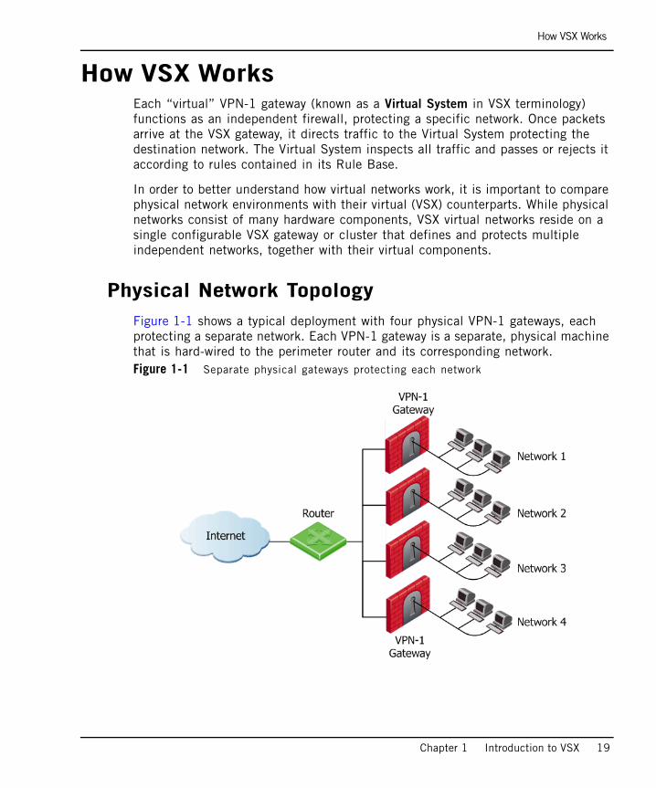
How VSX WorksEach “virtual” VPN-1 gateway (known as a Virtual System in VSX terminology) functions as an independent firewall, protecting a specific network. Once packets arrive at the VSX gateway, it directs traffic to the Virtual System protecting the destination network. The Virtual System inspects all traffic and passes or rejects it according to rules contained in its Rule Base.
In order to better understand how virtual networks work, it is important to compare physical network environments with their virtual (VSX) counterparts. While physical networks consist of many hardware components, VSX virtual networks reside on a single configurable VSX gateway or cluster that defines and protects multiple independent networks, together with their virtual components.
Physical Network TopologyFigure 1-1 shows a typical deployment with four physical VPN-1 gateways, each protecting a separate network. Each VPN-1 gateway is a separate, physical machine that is hard-wired to the perimeter router and its corresponding network.Figure 1-1 Separate physical gateways protecting each network
VSX Virtual Network Topology
20
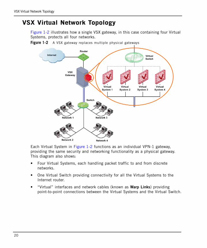
VSX Virtual Network TopologyFigure 1-2 illustrates how a single VSX gateway, in this case containing four Virtual Systems, protects all four networks.Figure 1-2 A VSX gateway replaces multiple physical gateways
Each Virtual System in Figure 1-2 functions as an individual VPN-1 gateway, providing the same security and networking functionality as a physical gateway. This diagram also shows:
• Four Virtual Systems, each handling packet traffic to and from discrete networks.
• One Virtual Switch providing connectivity for all the Virtual Systems to the Internet router.
• “Virtual” interfaces and network cables (known as Warp Links) providing point-to-point connections between the Virtual Systems and the Virtual Switch.
Key Features and Benefits
Chapter 1 Introduction to VSX 21
Key Features and Benefits
Scalable Virtual EnvironmentUp to 250 virtual devices can be deployed on a single VSX gateway or VSX cluster, providing a highly scalable virtual platform while reducing hardware investment, space requirements, and maintenance costs.
High Performance SecurityHigh-bandwidth networks require high-performance gateways in order to support thousands of applications and users. To provide security at wire speed, VSX can be deployed on multiple carrier-class platforms using Check Point’s SecureXL™ performance technology, ensuring secure, multi-gigabit throughput.
Virtual System Load Sharing (VSLS) provides the ability to distribute Virtual Systems across cluster members, effectively distributing Virtual System traffic load within a cluster.
VSX Resource Control allows administrators to manage the processing load by guaranteeing that each Virtual System will receive its minimum CPU allocation. Resources not needed by one Virtual System are automatically made available to other Virtual Systems.
VSX QoS Enforcement provides the ability to control network quality of service in the VSX network environment by supporting the Differentiated Services (DiffServe) protocol and assigning different transmission characteristics to different classes of service.
Non-Stop SecurityVSX supports the Check Point ClusterXL® technology as well as third-party cluster solutions, such as Crossbeam and Nokia, to guarantee nonstop security. Seamless connection failover promotes high availability and resiliency, ensuring, nonstop, secure business operations at both the application and network levels.

Active/Standby Bridge Mode
22
Active/Standby Bridge ModeThe Active/Standby Bridge Mode enhances network resiliency by enabling instantaneous failover and by providing full support for VSLS in the Bridge Mode. This feature also provides full control over bridge failover.
Typical VSX EnvironmentsVSX virtual networking provides an ideal solution for:
• Enterprises enforcing distinct security policies per department
• Internet service providers offering secure environments
• College campuses with many discrete networks for students, faculty and administration
• Any other large organization requiring multiple firewalls
In each case, VSX provides access control, NAT, VPN, remote access, logging, and SmartDefense services. For more detailed information regarding VSX deployments, see: Chapter 8, “Deploying VSX”.

23
Chapter 2VSX - Architecture and Concepts
In This Chapter
Overview page 24
The VSX Gateway page 25
Virtual Devices page 29
VSX Management Overview page 37
VSX Traffic Flow page 41
VSX Routing Concepts page 45
VSX Clusters page 52
Overview
24
OverviewThis chapter presents an overview of core VSX concepts and describes the architecture and building blocks that comprise a VSX virtual environment. This information is essential in order to plan, provision, configure, and operate a VSX virtual network deployment. VSX includes a robust set of virtual components that emulate the functionality of physical network devices. By using these virtual components, you can create network topologies that are functionally equivalent to physical networks.
The term “Virtual Devices” refers to Virtual Systems, Virtual Switches, and Virtual Routers.
This chapter also introduces the two principal management models with which you manage the VSX environment. Finally, this chapter describes several routing and traffic management features that are applicable to VSX environments.

The VSX Gateway
Chapter 2 VSX - Architecture and Concepts 25
The VSX GatewayA VSX gateway is a physical machine that hosts virtual “networks”, consisting of virtual devices that provide the functionality of their physical network counterparts such as: VPN-1 gateways, routers and switches.
A VSX gateway performs the following tasks:
• Communicates with the management server to handle provisioning and configuration for all virtual devices
• Manages state synchronization to for high availability and for load sharing in cluster deployments.
Management Server ConnectionsA management server (SmartCenter Server or Provider-1 MDS) connects to the VSX gateway and provides provisioning and configuration services for virtual devices located on the VSX gateway. You can connect the management server to the VSX gateway using one of the following scenarios.
• Local Connection: The management server connects directly to the VSX gateway via a dedicated management interface.
• Remote Connection: The management server connects remotely from an external or internal network by means of a router connected to a management interface. This method ensures segregation of management traffic from all other traffic.
Management Server Connections
26
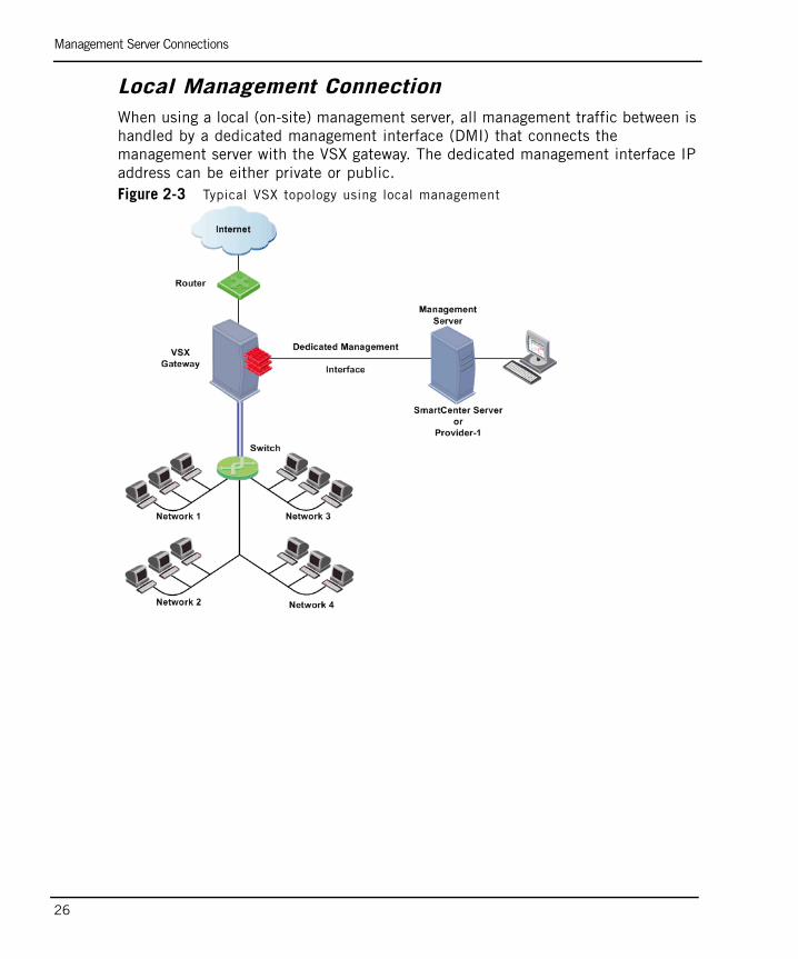
Local Management ConnectionWhen using a local (on-site) management server, all management traffic between is handled by a dedicated management interface (DMI) that connects the management server with the VSX gateway. The dedicated management interface IP address can be either private or public. Figure 2-3 Typical VSX topology using local management

Management Server Connections
Chapter 2 VSX - Architecture and Concepts 27
Remote Management connectionWhen using a remote management server (SmartCenter server or Provider-1), management traffic travels via an internal or external network to a VSX gateway to the management interface. This architecture segregates management traffic from all other traffic passing through the VSX gateway.
Check Point recommends that remote management connections use a dedicated management interface (DMI) that connects directly to a router or switch that leads to the external network or the Internet. The following diagram illustrates this scenario.Figure 2-4 Typical VSX deployment with DMI remote management
You can choose to use a non-dedicated management interface by connecting a Virtual Router or Virtual Switch to the management interface. This, however, is not recommended.
When management traffic passes through a Virtual Router or Switch, you must ensure that the associated Warp Link IP address originates from the remote network. Furthermore, if the remote management connection arrives via the Internet, you must assign a routable, public IP address.

Management Interface
28
Management InterfaceA VSX deployment can be managed using one of the following interface schemes:
• Dedicated Management Interface (DMI): Uses a separate interface that is restricted to management traffic, such as provisioning, logging and monitoring
• Non-Dedicated Management Interface: Uses a shared internal or external interface that also carries routine user traffic
Dedicated Management Interface (DMI)Check Points recommends that you use a DMI for management for the following reasons:
• Segregation of management traffic from routine “production” traffic enhance performance, especially for end users
• Enables several advanced VSX features
Non-Dedicated Management InterfaceVSX supports non-DMI deployments primarily to provide backward compatibility with legacy deployments. When configuring a non-DMI deployment, you can define remote management connections only via a Virtual Switch or Virtual Router. Remote management connects via a Virtual System are not supported.
Check Point does not recommend using non-DMI for the following reasons:
• Provisioning and logging may degrade user performance
• Does not support several new VSX features
• Non-DMI is irreversible - you cannot change a non-DMI gateway to DMI

Virtual Devices
Chapter 2 VSX - Architecture and Concepts 29
Virtual DevicesIn This Section
This section describes virtual network components and their characteristics.
Virtual SystemA Virtual System is a virtual security and routing domain that provides the functionality of a VPN-1 gateway with full firewall and VPN facilities. Multiple Virtual Systems can run concurrently on a single VSX gateway.
Virtual System AutonomyEach virtual system functions as a stand-alone, independent entity, much in the same way as each VPN-1 gateway is independent from other gateways. Each Virtual System maintains its own interfaces, IP addresses, routing table, ARP table and dynamic routing configuration. In addition, each Virtual System maintains its own:
• State Tables: Each Virtual System contains its own kernel tables containing configuration and runtime data, such as, active connections, IPSec tunnel information, etc.
• Security and VPN policies: Each Virtual System enforces its own security and VPN Policies (including INSPECT code). Policies are retrieved from the management server and stored separately on the local disk and in the kernel. In a Provider-1 environment, each customer database is maintained separately on the management server as well as on the VSX gateway.
• Configuration Parameters: Each Virtual System maintains its own configuration, such as SmartDefense settings, TCP/UDP time-outs, etc.
• Logging Configuration: Each Virtual System maintains its own logs and performs logging according to its own rules and configuration.
Virtual System page 29
Virtual System in Bridge Mode page 30
Virtual Routers page 31
Virtual Switches page 32
Interfaces page 33
Virtual System in Bridge Mode
30
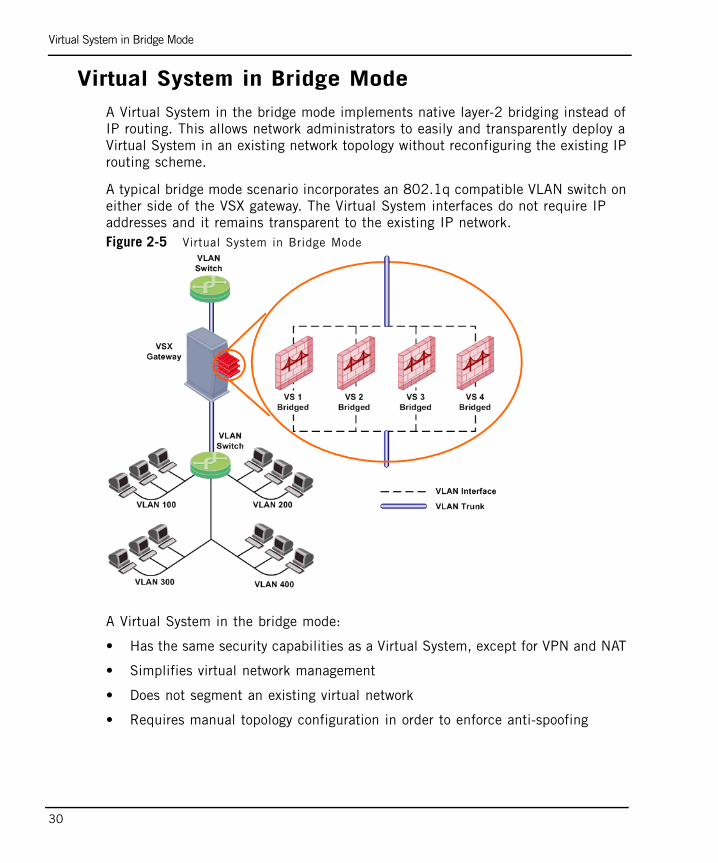
Virtual System in Bridge ModeA Virtual System in the bridge mode implements native layer-2 bridging instead of IP routing. This allows network administrators to easily and transparently deploy a Virtual System in an existing network topology without reconfiguring the existing IP routing scheme.
A typical bridge mode scenario incorporates an 802.1q compatible VLAN switch on either side of the VSX gateway. The Virtual System interfaces do not require IP addresses and it remains transparent to the existing IP network.Figure 2-5 Virtual System in Bridge Mode
A Virtual System in the bridge mode:
• Has the same security capabilities as a Virtual System, except for VPN and NAT
• Simplifies virtual network management
• Does not segment an existing virtual network
• Requires manual topology configuration in order to enforce anti-spoofing

Virtual Routers
Chapter 2 VSX - Architecture and Concepts 31
Virtual Routers A Virtual Router is an independent routing domain within a VSX gateway that performs the functionality of physical routers. Virtual Routers are useful for connecting multiple Virtual Systems to a shared interface, such as the interface leading to the Internet, and for routing traffic from one Virtual System to another. Virtual Routers support dynamic routing.
Virtual Routers perform the following routing functions:
• Packets arriving at the VSX gateway through a shared interface to the designated Virtual System based on the source or destination IP address.
• Traffic arriving from Virtual Systems directed to a shared interface or to other Virtual Systems.
• Traffic to and from shared network resources such as DMZs.
As with physical routers, each Virtual Router maintains a routing table with a list of route entries describing known networks and directions on how to reach them. Depending on the deployment requirements multiple Virtual Routers can be configured.
To protect themselves, Virtual Routers inspect all traffic destined to, or emanating from themselves (for example, an ICMP ping to the Virtual Router IP address) based on the security policy. Traffic that is not destined to, or emanating from the Virtual Router is not inspected by the Virtual Router policy and is forwarded to its destination.

Virtual Switches
32
Virtual SwitchesBy providing layer-2 connectivity, a Virtual Switch connects Virtual Systems and facilitates sharing a common physical interface without segmenting the existing IP network. As with a physical switch, each Virtual Switch maintains a forwarding table with a list of MAC addresses and their associated ports.
In contrast to a Virtual Router, when sharing a physical interface via a Virtual Switch there is no need:
• To allocate an additional subnet for IP addresses of Virtual Systems connected to the switch.
• To manually configure the routing on the routers adjacent to the shared interface.
You can create multiple Virtual Switches in a virtual network topology.
Note - When sharing a physical interface via a Virtual Switch, the IP addresses for Virtual Systems connected to a Virtual Switch should be allocated from the same subnet as the shared interface.
If the only function the Virtual Switch performs is to connect Virtual Systems, then the Virtual Switch can be defined without interfaces (unless Virtual System load sharing is enabled).
Interfaces
Chapter 2 VSX - Architecture and Concepts 33
Interfaces
In This Section
This section describes the various types of interfaces and how they are used in a VSX configuration. The principal interface types are:
• Physical Interface
• VLAN interface
• Warp Link (including unnumbered interfaces)
Physical Interfaces page 35
VLAN Interfaces page 35
Warp Links page 35
Unnumbered Interfaces page 36

Interfaces
34
The following figure presents a simple example that illustrates how the various interface types are used in a VSX environment.
Figure 2-6 VSX interface types
In Figure 2-6:
• Warp Links connect the Virtual Switch to each Virtual System.
• A Physical Interface connects the Virtual Switch to an external router leading to the Internet.
• VLAN Interfaces connect the Virtual Systems to the VLAN Switch, via A VLAN trunk.
• The VLAN switch connects to the protected networks.

Interfaces
Chapter 2 VSX - Architecture and Concepts 35
Physical InterfacesPhysical interfaces connect a VSX gateway to internal and external networks, as well as to the management server.There are three types of physical interfaces (four types for a VSX Cluster) used in a VSX gateway:
• Dedicated Management Interface: Connects the VSX gateway to the management server when it is locally managed. If the VSX gateway is remotely managed, then the management connection arrives via the external or internal interface.
• External interface: Connects the VSX gateway to the Internet or other untrusted networks.
• Internal Interface: Connects the VSX gateway to a protected network.
• Synchronization Interface: Connects one VSX gateway member to other members for state synchronization in a VSX clustering deployment.
Additional physical interfaces can be installed and attached to any virtual device as required. A VSX gateway can theoretically contain as many physical interfaces as permitted by gateway hardware and memory constraints.
VLAN InterfacesVirtual Systems typically connect to protected VLAN networks using IEEE 802.1q compliant VLAN Interfaces. The networks are connected to ports on an 802.1q-compliant switch that trunks all traffic via a single physical interface to the VSX gateway.
VSX uses VLAN tags to direct the Ethernet frames to the specific Virtual System handling each network. VSX assigns a virtual VLAN interface to each VLAN tag on a specific physical interface. For Example: VLAN tag 100 on eth3 will be assigned a virtual interface named eth3.100.
Warp LinksA Warp Link is a virtual point-to-point connection between a Virtual System and a Virtual Router or Virtual Switch. Each side of a Warp Link represents is a virtual interface with the appropriate virtual device.
VSX automatically assigns a name to each virtual interface when the administrators creates the link. Warp Interfaces on the Virtual System side are assigned the prefix wrp and those on the Virtual Router/Switch side are assigned the prefix wrpj. In both cases, VSX appends a unique number to the prefix to form the interface name.
When connected to a Virtual Switch, VSX also assigns a unique MAC address to each Warp Link.

Interfaces
36
Unnumbered Interfaces VSX NGX R65 allows you reduce the number of IP addresses required for a VSX network deployment when using one or more Virtual Routers. A Warp link connected to a Virtual Router can “borrow” an existing IP address from another interface, instead of assigning a dedicated address to the interface leading to a Virtual Router. This capability is known as an Unnumbered Interface. Figure 2-7 Unnumbered interfaces
The above figure illustrates a topology using unnumbered interfaces. In this example, the external interfaces for each Virtual System are unnumbered and borrow the IP address of the internal interfaces. Unnumbered interfaces act as the next hop from the Virtual Router.
Unnumbered Interface Limitations
The following limitations apply to Unnumbered Interfaces:
• Unnumbered interfaces must connect to a Virtual Router.
• You can only “borrow” an individual interface IP address once.
• In order to use VPN or Hide NAT, the borrowed address must be routable.
For configuration information, see: “Configuring Connections Leading to Virtual Routers” on page 109.

VSX Management Overview
Chapter 2 VSX - Architecture and Concepts 37
VSX Management OverviewIn This Section
IntroductionVSX supports two Check Point management models: SmartCenter and Provider-1. Both models provide central configuration, management and monitoring for multiple VSX gateways and Virtual Systems. The choice of management model depends on several factors, including:
• The scale of the current deployment and anticipated expansion
• Administrative requirements
• Physical and operational requirements
• Licensing restrictions
You can use either management model to manage “physical” VPN-1 gateways together with VSX gateways and Virtual Systems. You can also manage VPN communities and remote connections with either model.
Introduction page 37
SmartCenter Management Model page 38
Provider-1 Management Model page 39
Management Model Comparison page 40
Management Server Communication - SIC page 40
Note - According to the Check Point EULA (End User License Agreement), a SmartCenter server can only manage security policies for Virtual Systems belonging to a single legal entity. In order to manage Virtual Systems belonging to multiple legal entities, you need to deploy a Provider-1 management solution with a separate CMA for each legal entity. For more information regarding Licensing, refer to your Check Point Reseller.
SmartCenter Management Model
38
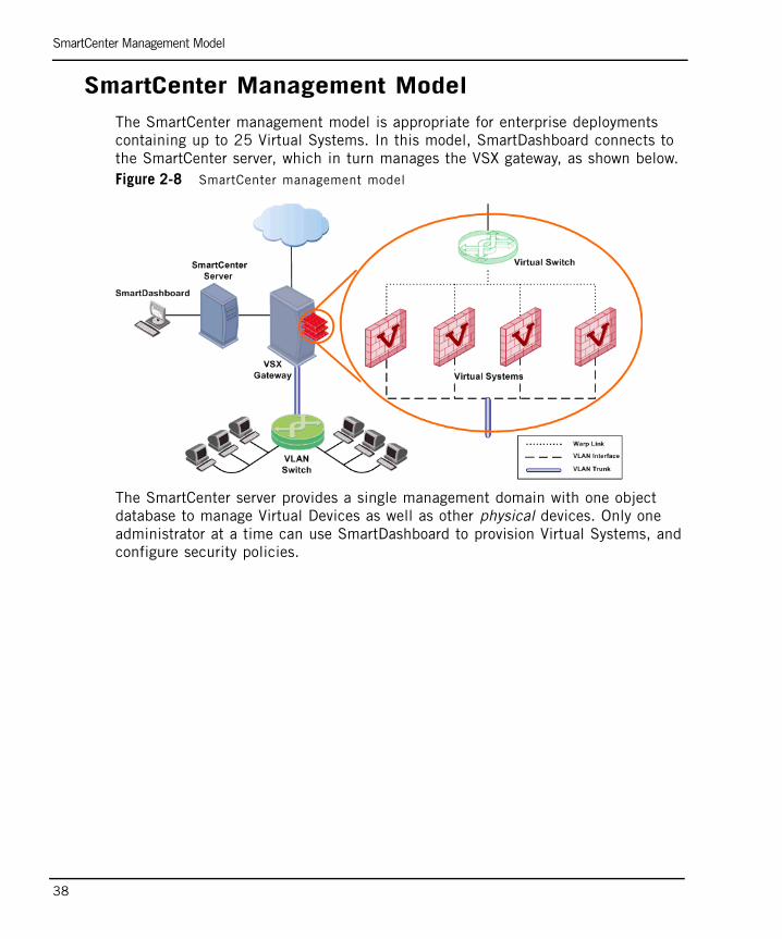
SmartCenter Management ModelThe SmartCenter management model is appropriate for enterprise deployments containing up to 25 Virtual Systems. In this model, SmartDashboard connects to the SmartCenter server, which in turn manages the VSX gateway, as shown below.Figure 2-8 SmartCenter management model
The SmartCenter server provides a single management domain with one object database to manage Virtual Devices as well as other physical devices. Only one administrator at a time can use SmartDashboard to provision Virtual Systems, and configure security policies.

Provider-1 Management Model
Chapter 2 VSX - Architecture and Concepts 39
Provider-1 Management ModelUsing the Provider-1 model, administrators centrally manage multiple independent networks, typically belonging to different customers, divisions or branches. The Multi-Domain Server (MDS) is the central management node that controls the network and security policy databases for each of these networks.
Each customer network is managed by a Customer Management Add-On (CMA), which provides the full functionality of a SmartCenter server and can host multiple Virtual Systems, virtual devices and physical devices. The CMA that manages the VSX gateway itself is known as the Main CMA.
Check Point recommends that each VSX gateway in a Provider-1 deployment be managed by its own, separate, Main CMA. A VSX gateway can host Virtual Systems that are managed by different CMAs, as shown in Figure 2-9.Figure 2-9 Provider-1 management model
Using the Multi-Domain GUI (MDG), you provision and configure customers and CMAs. Each CMA uses its own SmartDashboard instance to provision its Virtual Systems and other virtual devices as well as to configure their security policies.

Management Model Comparison
40
Management Model ComparisonThe following table summarizes the capabilities and differences between the two management models. The capacity figures shown for Provider-1 represent estimated, practical limits that will sustain acceptable performance levels under normal conditions. Actual capacities and performance are a dependent on many factors, including deployed hardware, network topology, traffic load and security requirements.
Management Server Communication - SICAll communication between the management server and the VSX gateway is accomplished by means of Secure Internal Communication (SIC), a certificate based channel that authenticates communication between Check Point components. The management server uses SIC for provisioning virtual devices, policy installation, logging, and status monitoring.
SIC trust is initially established using a one-time password during configuration of the VSX gateway or cluster members. For Provider-1 deployments, SIC trust is established between the CMA associated with the VSX gateway or cluster (Main CMA).
Virtual devices establish trust in a different manner than their physical counterparts. When creating a virtual device, VSX automatically establishes SIC trust using the secure communication channel defined between the management server and the VSX gateway. The VSX gateway uses its management interface for Secure Internal Communication between the management server and all virtual devices.
Figure 2-10 VSX Management Model Comparison
SmartCenter Server Provider-1 (Practical Limit)
Management Domains 1 250
Concurrent Administrators 1 250
Object Databases 1 250
Policies 250 250
Certificate Authorities 1 250
Virtual Systems 25 (recommended) 250

VSX Traffic Flow
Chapter 2 VSX - Architecture and Concepts 41
VSX Traffic Flow
OverviewThe VSX gateway processes traffic according to the following steps:
• Context determination
• Security enforcement
• Forwarding to destination
Context DeterminationVSX NGX R65 incorporates VRF (Virtual Routing and Forwarding) technology that allows creation of multiple, independent routing domains on a single VSX gateway or cluster. The independence of these routing domains makes possible the use of virtual devices with overlapping IP addresses. Each routing domain is known as a context.
When traffic arrives at a VSX gateway, a process known as Context Determination directs traffic to the appropriate Virtual System, Virtual Router or Virtual Switch. The context determination process depends on the virtual network topology and the connectivity of the virtual devices.
The three basic Virtual System connection scenarios are:
• Virtual System directly connected to a physical or VLAN interface
• Virtual System connected via a Virtual Switch
• Virtual System connected via a Virtual Router

Context Determination
42
Direct Connection to a Physical InterfaceWhen traffic arrives at an interface (either physical or VLAN) that directly connects to a Virtual System, the connection itself determines the context and traffic passes directly to the appropriate Virtual System via that interface. In the following example, VSX automatically directs traffic arriving via VLAN Interface eth1.200 to Virtual System 2 according to the context defined by the VLAN ID.Figure 2-11 Directly connected interface example
Context Determination
Chapter 2 VSX - Architecture and Concepts 43
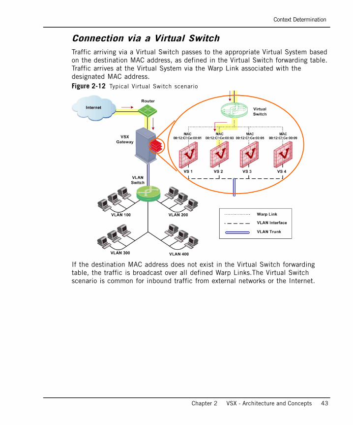
Connection via a Virtual SwitchTraffic arriving via a Virtual Switch passes to the appropriate Virtual System based on the destination MAC address, as defined in the Virtual Switch forwarding table. Traffic arrives at the Virtual System via the Warp Link associated with the designated MAC address. Figure 2-12 Typical Virtual Switch scenario
If the destination MAC address does not exist in the Virtual Switch forwarding table, the traffic is broadcast over all defined Warp Links.The Virtual Switch scenario is common for inbound traffic from external networks or the Internet.
Security Enforcement
44
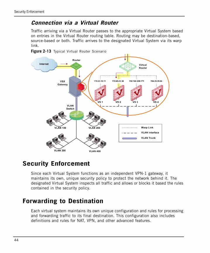
Connection via a Virtual RouterTraffic arriving via a Virtual Router passes to the appropriate Virtual System based on entries in the Virtual Router routing table. Routing may be destination-based, source-based or both. Traffic arrives to the designated Virtual System via its warp link.Figure 2-13 Typical Virtual Router Scenario
Security EnforcementSince each Virtual System functions as an independent VPN-1 gateway, it maintains its own, unique security policy to protect the network behind it. The designated Virtual System inspects all traffic and allows or blocks it based the rules contained in the security policy.
Forwarding to DestinationEach virtual system maintains its own unique configuration and rules for processing and forwarding traffic to its final destination. This configuration also includes definitions and rules for NAT, VPN, and other advanced features.

VSX Routing Concepts
Chapter 2 VSX - Architecture and Concepts 45
VSX Routing ConceptsIn This Section
Routing OverviewThe traffic routing features in VSX network topologies are analogous to those available for physical networks. This section discusses several routing features and strategies as they apply to a VSX environment.
Routing Overview page 45
Routing Between Virtual Systems page 46
Overlapping IP Address Space page 48
Source-Based Routing page 49
NAT page 50
Dynamic Routing page 51

Routing Between Virtual Systems
46
Routing Between Virtual SystemsVirtual Routers and Switches can be used to forward traffic between networks located behind virtual systems, much in the same manner as their physical counterparts.
Figure 2-14 presents an example of how Virtual Systems connected to a Virtual Switch and a physical VLAN switch communicate with each other. In this example, a host in VLAN 100 sends data to a server located in VLAN 200. Figure 2-14 Routing of virtual traffic between Virtual Systems
1. Traffic from the VLAN 100 host arrives at the VLAN switch, which inserts a VLAN tag and passes it to the VSX gateway via a VLAN trunk.
2. Based on its VLAN tag, the VSX gateway assigns the traffic to the Virtual System named VS1. VS1 inspects the traffic according to its security policy and forwards the traffic on to the Virtual Switch.
3. VS1 “knows” to forward the traffic to VS2 via the Virtual Switch based on its routing configuration.
4. VS2 inspects the traffic according to its security policy, inserts a VLAN tag, and passes it to back the VLAN switch.
5. The VLAN switch forwards the traffic to the server located on VLAN 200.

Routing Between Virtual Systems
Chapter 2 VSX - Architecture and Concepts 47
Route PropagationWhen a Virtual System is connected to a Virtual Router or to a Virtual Switch, you can choose to propagate its routing information to adjacent Virtual Devices. This feature enables network nodes located behind neighboring Virtual Systems to communicate without the need for manual configuration.
Route propagation works by automatically updating virtual device routing tables with routes leading to the appropriate Virtual Systems.
Route Propagation using a Virtual Router
When Virtual Systems are connected to a Virtual Router, VSX propagates routes by automatically adding entries to the routing table contained in the Virtual Router. Each entry contains a route pointing to the destination subnet using the Virtual System router-side Warp Interface (wrpj) as the next hop.
Route Propagation using a Virtual Switch
When Virtual Systems are connected to a Virtual Switch, VSX propagates routes by automatically adding entries to the routing table in each Virtual System. Each entry contains a route pointing to the destination subnet using the Virtual System Warp Interface (wrp) IP address.
Additional Considerations for Virtual Switch Route Propagation
To update the topology map for each Virtual System, you still need to edit and save each Virtual System object that is connected to the Virtual Switch after enabling route propagation. You do not, however, need to manually define the topology, as this is done automatically.
Following the topology update, you must then re-install the security policy for the affected Virtual Systems. This procedure is necessary in order to ensure that the Anti-Spoofing and VPN features work properly.

Routing Between Virtual Systems
48
Overlapping IP Address SpaceVSX facilitates connectivity when multiple network segments share the same IP address range (IP address space). This scenario occurs when a single VSX gateway protects several independent networks that assign IP addresses to endpoints from the same pool of IP addresses. Thus, it is feasible that more than one endpoint in a VSX environment will have the identical IP address, provided that each is located behind different Virtual System.
Overlapping IP address space in VSX environments is possible because each Virtual Systems maintains its own unique state and routing tables. These tables can contain identical entries, but within different, segregated contexts. Virtual Systems use NAT to facilitate mapping internal IP addresses to one or more external IP addresses.
Figure 2-15 demonstrates how traffic passes from the Internet to an internal network with overlapping IP address ranges, using NAT at each Virtual System.

Source-Based Routing
Chapter 2 VSX - Architecture and Concepts 49
Figure 2-15 Forwarding traffic with overlapping IP addresses
In this case, Network 1, Network 2 Network 3, and Network 4 all share the same network address pool, which might result in identical overlapping IP addresses. However, packets originating from or targeted to these networks are processed by their respective Virtual System using NAT to translate the original/overlapping addresses to unique routable addresses.
Source-Based RoutingSource-based routing allows you to define routing definitions that take precedence over ordinary, destination-based, routing decisions. This allows you to route packets according to their source IP address or a combination of their source IP address and destination IP address.
Source-based routing is useful in deployments where a single physical interface without VLAN tagging connects several protected customer networks. Each Virtual System is connected to an internal Virtual Router. The Virtual Router routes traffic to the appropriate Virtual System based on the source IP address, as defined in source-based routing rules.
NAT
50
Limitations• Source-based routing does not support overlapping IP addresses.
• Anti-spoofing protection is not effective for packets origination form a shared internal interface because there is no physical or logical segregation of traffic. In this case, it is recommended that you deploy anti-spoofing protection on the router itself.
Refer to “Defining Source-Based Routing Rules” on page 100 for details regarding
NATVirtual Systems support Network Address Translation (NAT), much in the same manner as a physical firewall. When a Virtual System, using either Static or Hide NAT, connects to a Virtual Router, you must propagate the affected routes to the virtual router. To do so, you need to first define the NAT addresses in the Virtual System topology.
For information regarding NAT configuration for a Virtual System, refer to “Virtual System - NAT” on page 87.

Dynamic Routing
Chapter 2 VSX - Architecture and Concepts 51
Dynamic RoutingVirtual Devices can communicate and distribute routes amongst themselves using dynamic routing. VSX NGX R65 provides full layer-3 dynamic routing for Virtual Systems and Virtual Routers. The following unicast and multicast dynamic routing protocols are supported:
• OSPF
• RIP-v2
• BGP-v4
• IGMP
• PIM-SM
• PIM-DM
Dynamic routing is configured and stored separately for each Virtual Device. Each Virtual Devices has its own dynamic routing daemon.

VSX Clusters
52
VSX ClustersA VSX cluster consists of two or more identical, interconnected VSX gateways that ensure continuous data synchronization and transparent failover. Furthermore, Virtual System Load Sharing (VSLS) enhances throughput by distributing Virtual Systems, together with their traffic load, amongst multiple, redundant machines.
VSX supports the following cluster environments:
• Check Point ClusterXL
• Crossbeam X-Series Chassis
• Nokia VRRP Appliances
VSX NGX R65 supports the following Bridge Mode solutions for ClusterXL deployments:
• STP Bridge Mode: Provides path redundancy while preventing undesirable loops between redundant switches.
• Active/Standby Bridge Mode: Provides full path redundancy and loop prevention, while offering seamless support for Virtual System Load Sharing and overcomes many STP limitations.
For more details regarding VSX clustering scenarios and features, refer to Chapter 5, “Introduction to VSX Clusters”.
High AvailabilityVSX NGX R65 provides for high system availability by ensuring transparent failover for VSX gateways and/or for individual Virtual Systems. If the active VSX gateway member fails, all sessions continue to run, securely and without interruption, on a standby cluster member. If an individual Virtual System fails, you can configure that Virtual System to fail over to a standby member while all other Virtual Systems continue to function on the active VSX gateway member.
Users need not reconnect and re-authenticate, nor do they notice that an alternate machine has taken over. The Selective Sync features allows you to selectively activate, delay or disable cluster member synchronization.

Virtual System Load Sharing (VSLS)
Chapter 2 VSX - Architecture and Concepts 53
Virtual System Load Sharing (VSLS)Load Sharing offers significant performance advantages while providing failover for individual Virtual Systems. Using multiple gateways instead of a single gateway significantly increases linear performance for CPU intensive applications such as VPNs, Security servers, Policy servers, and SmartDirectory (LDAP).
By distributing Virtual System instances between different cluster members, the performance load is efficiently spread amongst the members. For example, active Virtual System 1 runs on member A, while active Virtual System 2 runs on member B. Standby and backup Virtual system instances are likewise distributed amongst members to maximize throughput, even in a failover scenario.
VSLS provides an excellent scalability solution, allowing administrators to add additional physical members to an existing VSLS cluster as traffic loads and performance requirements increase.
VSLS is available only in a Check Point ClusterXL environment.

Virtual System Load Sharing (VSLS)
54
55
Chapter 3Configuring VSX
In This Chapter
Overview page 56
Working with VSX Gateways page 57
Working with Virtual Systems page 73
Working with Virtual Routers page 90
Working with Virtual Switches page 102
Working with Interface Definitions page 107
Working with Network Address Translation page 121
Authentication page 114
Tracking Activity with SmartView Monitor page 123
Tracking Activity with SmartView Monitor page 123

Overview
56
OverviewThis chapter presents procedures for configuring and managing a VSX virtual network environment. All procedures for provisioning and configuring Virtual systems and other virtual devices are performed using SmartDashboard.
When defining or configuring VSX objects in a Provider-1 deployment, open the SmartDashboard associated with the specific CMA containing the Virtual System or other virtual devices. Procedures that are specific to Provider-1 deployments are presented in Chapter 4, “Using VSX With Provider-1”.
In order to perform any of the procedures presented in this chapter, both the VSX gateway and the management servers (Provider-1 MDS and/or SmartCenter server) must be running. You should already have installed the appropriate GUI clients (SmartDashboard and Provider-1 MDG if required) on the appropriate machines.
This chapter covers the following areas:
• Creating and configuring a VXS Gateway
• Creating and configuring Virtual Systems
• Creating and configuring Routers and Switches
• Working with interfaces
• Logging and tracking VSX network activity
This chapter assumes that the user familiar with SmartDashboard, its GUI elements and the procedures for defining standard VPN-1 objects. Refer to the SmartCenter Administration Guide for details.
Many virtual device definitions are identical to those for their physical, VPN-1 counterparts. Detailed procedures for defining such objects and properties are not replicated in this guide. Please refer to the Firewall and SmartDefense Administration Guide for details.
Rules & Security PoliciesThe procedures for defining and installing security policies on a VSX gateways and Virtual Systems are identical to those for physical VPN-1 gateway. Accordingly, these procedures and not presented in this Administration Guide. For detailed information regarding security policies and standard object definitions, refer to the Firewall and SmartDefense Administration Guide and the SmartCenter Administration Guide.

Working with VSX Gateways
Chapter 3 Configuring VSX 57
Working with VSX GatewaysIn This Section.
A VSX gateway is a physical machine that serves as a container hosting Virtual Systems and other virtual network components. This section presents step-by-step procedures for creating and configuring stand alone VSX gateways. Procedures for defining VSX clusters appear in Chapter 6, “Managing VSX Clusters”.
Creating a New VSX GatewayThis section describes how to create a new VSX gateway using the VSX Gateway Wizard. The VSX gateway Wizard guides you through the following steps to configure a VSX gateway.
After completing the VSX Gateway Wizard, you can modify the VSX gateway definition directly from SmartDashboard. For example, you can add or delete interfaces, or configure existing interfaces to support VLANs.
To use the VSX Gateway wizard, perform the following steps:
1. Open SmartDashboard. If you are using Provider-1, open SmartDashboard from the CMA in which you are creating the VSX gateway.
2. In the Network Objects tab in the Objects Tree, right-click Check Point and select New Check Point > VPN-1 Power VSX > Gateway. The VSX Gateway wizard opens displaying the General Properties page.
Creating a New VSX Gateway page 57
Modifying VSX Gateway Definitions page 65
Deleting a VSX Gateway page 72
VSX Gateway Recovery page 72
Defining VSX Gateway General Properties page 58
Selecting Creation Templates page 59
Establishing SIC Trust page 60
Defining Physical Interfaces page 61
VSX Gateway Wizard - Management page 62
Virtual Network Device Configuration page 63
Completing the VSX Wizard page 64
Creating a New VSX Gateway
58
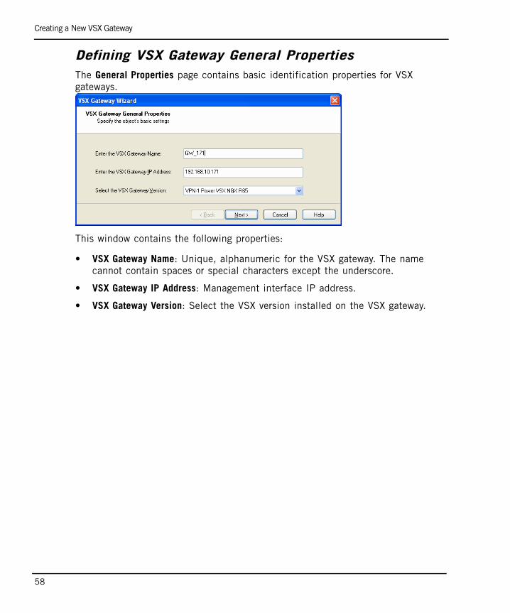
Defining VSX Gateway General PropertiesThe General Properties page contains basic identification properties for VSX gateways.
This window contains the following properties:
• VSX Gateway Name: Unique, alphanumeric for the VSX gateway. The name cannot contain spaces or special characters except the underscore.
• VSX Gateway IP Address: Management interface IP address.
• VSX Gateway Version: Select the VSX version installed on the VSX gateway.
Creating a New VSX Gateway
Chapter 3 Configuring VSX 59
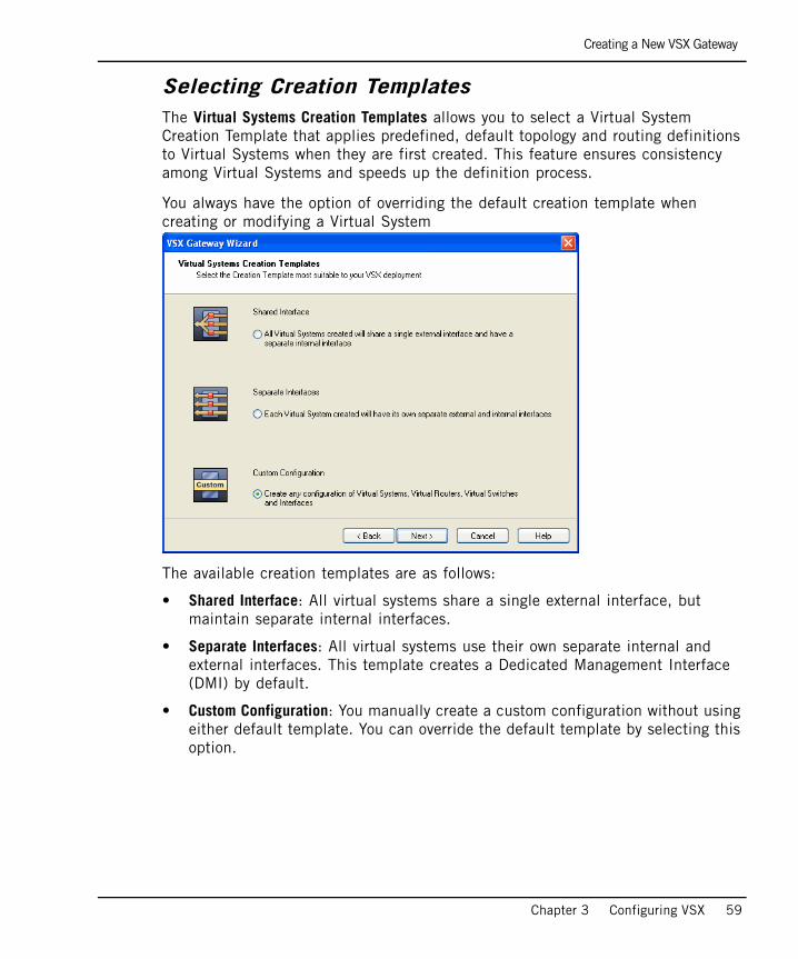
Selecting Creation TemplatesThe Virtual Systems Creation Templates allows you to select a Virtual System Creation Template that applies predefined, default topology and routing definitions to Virtual Systems when they are first created. This feature ensures consistency among Virtual Systems and speeds up the definition process.
You always have the option of overriding the default creation template when creating or modifying a Virtual System
The available creation templates are as follows:
• Shared Interface: All virtual systems share a single external interface, but maintain separate internal interfaces.
• Separate Interfaces: All virtual systems use their own separate internal and external interfaces. This template creates a Dedicated Management Interface (DMI) by default.
• Custom Configuration: You manually create a custom configuration without using either default template. You can override the default template by selecting this option.
Creating a New VSX Gateway
60
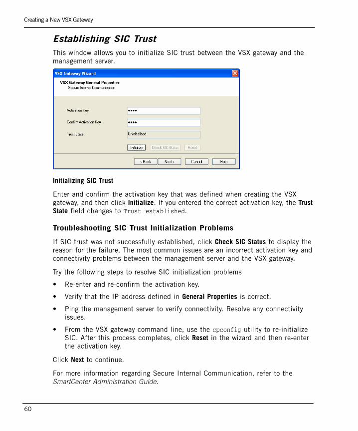
Establishing SIC Trust This window allows you to initialize SIC trust between the VSX gateway and the management server.
Initializing SIC Trust
Enter and confirm the activation key that was defined when creating the VSX gateway, and then click Initialize. If you entered the correct activation key, the Trust State field changes to Trust established.
Troubleshooting SIC Trust Initialization Problems
If SIC trust was not successfully established, click Check SIC Status to display the reason for the failure. The most common issues are an incorrect activation key and connectivity problems between the management server and the VSX gateway.
Try the following steps to resolve SIC initialization problems
• Re-enter and re-confirm the activation key.
• Verify that the IP address defined in General Properties is correct.
• Ping the management server to verify connectivity. Resolve any connectivity issues.
• From the VSX gateway command line, use the cpconfig utility to re-initialize SIC. After this process completes, click Reset in the wizard and then re-enter the activation key.
Click Next to continue.
For more information regarding Secure Internal Communication, refer to the SmartCenter Administration Guide.

Creating a New VSX Gateway
Chapter 3 Configuring VSX 61
Defining Physical InterfacesThe VSX Gateway Interfaces window allows you define physical interfaces as VLAN trunks. The list displayed contains all interfaces currently defined on the gateway machine.
.
Enable an interface to define it as a VLAN trunk. Clear an interface to remove the VLAN trunk assignment.

Creating a New VSX Gateway
62
VSX Gateway Wizard - ManagementThe VSX Gateway Management page allows you to define several security policy rules that protect the VSX gateway itself. This policy is installed automatically on the new VSX gateway.
The security policy consists of predefined rules covering the following services:
• UDP: snmp requests
• TCP: ssh traffic
• ICMP: echo-request (ping)
• TCP: https traffic
Configuring the Gateway Security Policy
1. Allow: Enable a rule to allow traffic for those services for which you wish to allow traffic. Clear a rule to block traffic. By default, all services are blocked.
For example, you may wish to allow ICMP echo-request traffic in order to be able to ping the gateway from the management server.
2. Source: Click the arrow and select a Source Object from the list. The default value is *Any. Click New Source Object to define a new source. Refer to the online help and the SmartCenter Administration Guide for further details.
Note - This policy applies only to traffic destined for the VSX gateway. Traffic destined for Virtual Systems, other Virtual Devices, external networks, and internal networks is not affected by this policy.

Creating a New VSX Gateway
Chapter 3 Configuring VSX 63
Virtual Network Device ConfigurationIf you chose the custom configuration option, the Virtual Network Device Configuration window appears. This window allows you to define a Virtual Device with a shared interface with the VSX gateway. If you do not wish to define a Virtual Device at this time, click Next to continue.
To define a virtual device with a shared interface, perform the following steps:
1. Enable the Create a Virtual Device option.
2. Select the virtual device type from the list (router or switch).
3. Select the shared interface from the list. Do not select the management interface if you wish to define a dedicated management interface (DMI) gateway. Select the management interface only if you wish to define a non-DMI gateway..
4. Define the IP address and net mask for a Virtual Router in the appropriate fields. These options are not available for a Virtual Switch.
5. Optionally, define a a default gateway for a Virtual Router. (DMI only)
Warning - This setting is irreversible once you complete the VSX Gateway wizard. This means that when you define a non-DMI gateway, you cannot change it to a DMI gateway later. If do not define a shared Virtual Device, a DMI gateway is created by default.
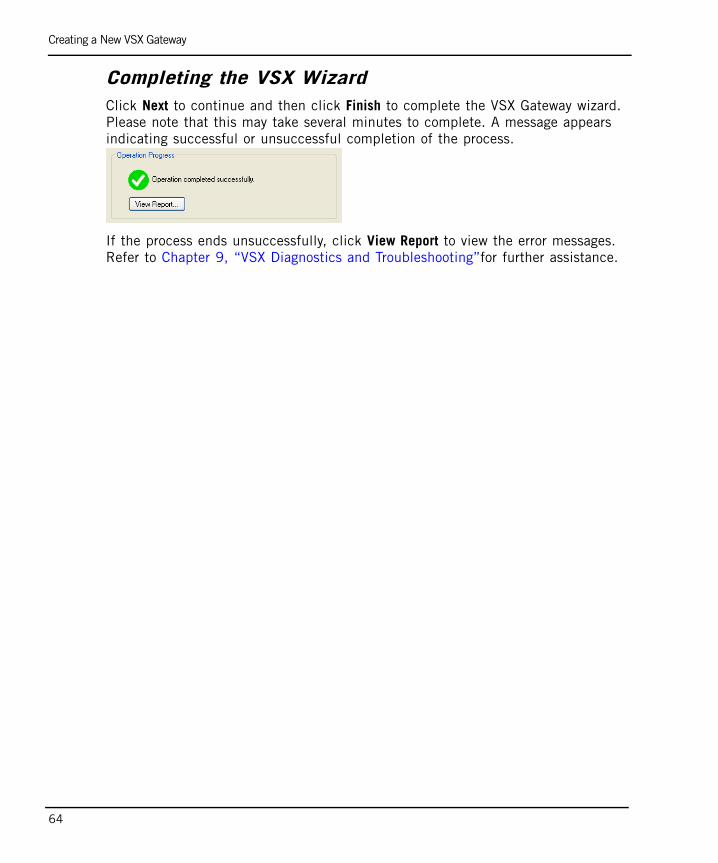
Creating a New VSX Gateway
64
Completing the VSX WizardClick Next to continue and then click Finish to complete the VSX Gateway wizard. Please note that this may take several minutes to complete. A message appears indicating successful or unsuccessful completion of the process.
If the process ends unsuccessfully, click View Report to view the error messages. Refer to Chapter 9, “VSX Diagnostics and Troubleshooting”for further assistance.

Modifying VSX Gateway Definitions
Chapter 3 Configuring VSX 65
Modifying VSX Gateway DefinitionsOnce you create a VSX gateway using the VSX Wizard, you can modify the topology and other parameters using the VSX Gateway Properties window. This window also allows you to configure many advanced features not available with the wizard.
To work with a VSX gateway definition, double-click on the VSX gateway object in the SmartDashboard Object Tree. The VSX Gateway Properties window opens, showing the General Properties page.
A brief explanation of each of the definition pages follows. More detailed explanations are available in the online help or in SmartCenter Administration Guide.
In This Section
VSX Gateway - General Properties page 66
VSX Gateway - Creation Templates page 68
VSX Gateway - Physical Interfaces page 68
VSX Gateway - Topology page 69
VSX Gateway - NAT page 71
VSX Gateway - SmartDefense page 71
VSX Gateway - VPN page 71
VSX Gateway - Remote Access page 71
VSX Gateway - Authentication page 71
VSX Gateway - Logs and Masters page 71
VSX Gateway - Capacity Optimization page 72
VSX Gateway - Advanced Pages page 72

Modifying VSX Gateway Definitions
66
VSX Gateway - General PropertiesUse the General Properties page to check and re-establish SIC trust as well as to activate Check Point products for use with this VSX gateway.
You can modify the following properties:
• Comment: Free text comment that appears in the Object List and elsewhere
• Color: Color of the object icon as it appears in the Object Tree
• Secure Internal Communication: Check and re-establish SIC trust as required
• Check Point Products: Select Check Point products active on this gateway
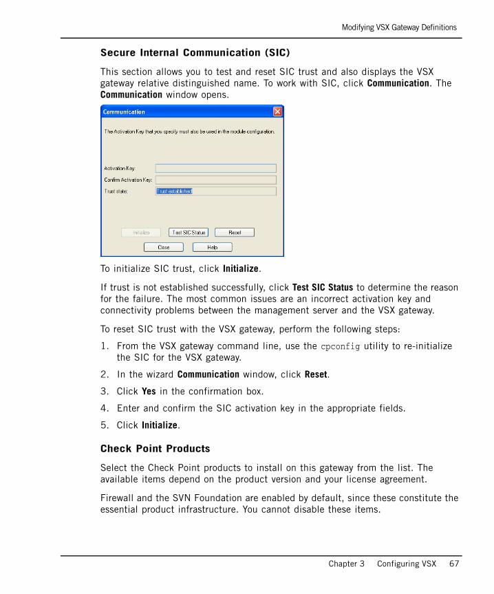
Modifying VSX Gateway Definitions
Chapter 3 Configuring VSX 67
Secure Internal Communication (SIC)
This section allows you to test and reset SIC trust and also displays the VSX gateway relative distinguished name. To work with SIC, click Communication. The Communication window opens.
To initialize SIC trust, click Initialize.
If trust is not established successfully, click Test SIC Status to determine the reason for the failure. The most common issues are an incorrect activation key and connectivity problems between the management server and the VSX gateway.
To reset SIC trust with the VSX gateway, perform the following steps:
1. From the VSX gateway command line, use the cpconfig utility to re-initialize the SIC for the VSX gateway.
2. In the wizard Communication window, click Reset.
3. Click Yes in the confirmation box.
4. Enter and confirm the SIC activation key in the appropriate fields.
5. Click Initialize.
Check Point Products
Select the Check Point products to install on this gateway from the list. The available items depend on the product version and your license agreement.
Firewall and the SVN Foundation are enabled by default, since these constitute the essential product infrastructure. You cannot disable these items.

Modifying VSX Gateway Definitions
68
VSX Gateway - Creation TemplatesThe Creation Templates page displays the creation template used to create the virtual systems for this gateway. You can change from the current creation template to the Custom Configuration template and change the shared physical interface if the Shared Interface template is active.
• Select the Custom Configuration option to change from the Shared Interfaces or Separate Interfaces templates. This effectively overrides the default template.
You cannot change back from the Custom Configuration template once you have completed the definition and saved it to the configuration to gateway.
• To change the shared interface, click Settings and select an interface from the list that appears.
VSX Gateway - Physical InterfacesThe Physical Interfaces page allows you to add or delete a physical interface on the VSX gateway, and to define interfaces to be used as VLAN trunks.
• To add a new physical interface, click Add and enter the interface name in the appropriate field.
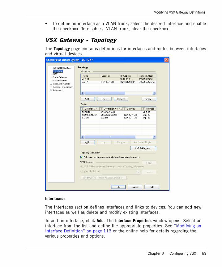
Modifying VSX Gateway Definitions
Chapter 3 Configuring VSX 69
• To define an interface as a VLAN trunk, select the desired interface and enable the checkbox. To disable a VLAN trunk, clear the checkbox.
VSX Gateway - TopologyThe Topology page contains definitions for interfaces and routes between interfaces and virtual devices.
Interfaces:
The Interfaces section defines interfaces and links to devices. You can add new interfaces as well as delete and modify existing interfaces.
To add an interface, click Add. The Interface Properties window opens. Select an interface from the list and define the appropriate properties. See “Modifying an Interface Definition” on page 113 or the online help for details regarding the various properties and options.
Modifying VSX Gateway Definitions
70
Routes
The Routes section defines routes between network devices, network addresses, and virtual devices. Some routes are defined automatically based on the interface definitions. You can add new routes as well as delete and modify existing routes.
To add a default route to the routing table, click Add Default Routes and either enter the default route IP address or select the default Virtual Router. The Route Configuration windows opens. Click Help for details regarding the various properties and options.
Calculating topology automatically based on routing information
Enable this option to allow VSX NGX R65 to automatically calculate the network topology based on interface and routing definitions (enabled by default). VSX NGX R65 creates a automatic links, or connectivity cloud objects linked to existing internal or external networks.
• This option is not available in the Bridge Mode.
• When employing dynamic routing, it is recommended to disable this option.
Note - If you wish to enable anti-spoofing protection when there are no routes pointing to internal networks, disable the Calculating topology option and modify the appropriate interface definitions to enable anti-spoofing.
Modifying VSX Gateway Definitions
Chapter 3 Configuring VSX 71
VSX Gateway - NATThis page contains various NAT options that are not relevant for VSX gateways.
VSX Gateway - SmartDefenseSince VSX gateways only use the default protection profile, the SmartDefense page is not relevant.
VSX Gateway - VPNThe VPN page contains a variety of configuration properties for VSX gateways in site-to-site VPN deployments. This window is only available if the Check Point VPN product is enabled on the General Properties page.
Please refer to the online help and the VPN Administration Guide for further details regarding VPN concepts and configuration.
VSX Gateway - Remote AccessThe Remote Access page contains properties that govern establishing VPN connections with Remote Access clients. This window is only available if the Check Point VPN product is enabled on the General Properties page.
Please refer to the online help and the VPN Administration Guide for further details regarding VPN with Remote Access clients.
VSX Gateway - AuthenticationThe Authentication page allows you to enable several different authentication options for a VSX gateway. Please refer to Authentication on page 114 for further details.
VSX Gateway - Logs and MastersThe Logs and Masters page allows you define logging options for a VSX gateway. Please refer to Tracking Activity with SmartView Monitor on page 123 for further details.

Deleting a VSX Gateway
72
VSX Gateway - Capacity OptimizationThe Capacity Optimization page allows you to maximize VSX gateway and VPN throughput by limiting the number of concurrent connections to the VSX gateway, the number of concurrent IKE negotiations, and the number of concurrent VPN tunnels.
To raise or lower the maximum, use the arrows in the appropriate field to set the desired value.
VSX Gateway - Advanced PagesThis page contains a variety of configuration options for SNMP, connection persistence and permissions to install policies. For further information regarding these options, please refer to the online help and the Firewall and SmartDefense Administration Guide.
Deleting a VSX GatewayDeleting a VSX gateway object automatically deletes all Virtual Systems and other virtual objects associated with that gateway. To delete a VSX gateway, right click the VSX gateway object on the Object Tree and click Delete. Select Yes in the confirmation box.
VSX Gateway RecoveryIn the event of a catastrophic VSX gateway failure, you can use the vsx_util command to restore the VSX gateway configuration as well as its virtual device configuration.
1. Reinstall the gateway and configure IP, net mask and default gateway.
2. Verify that all management interfaces have the same IP addresses as before.
3. From a command line interface on the management server, run vsx_util reconfigure to restore the previous configuration.

Working with Virtual Systems
Chapter 3 Configuring VSX 73
Working with Virtual SystemsIn This Section
This section presents procedures for creating and configuring Virtual Systems. The Virtual System definition process varies somewhat according to the template selected when creating the VSX gateway.
A typical Virtual System contains two interfaces:
• External interface leading to external networks, a DMZ, or the Internet
• Internal interface leading to internal networks or servers, often by means of a VLAN trunk
VSX NGX R65 supports up to 64 interfaces per virtual device and a total of up to 4096 interfaces per gateway or cluster.
You can add as many interfaces to a Virtual System as required by your environment, subject to system resource limitations.
Creating a New Virtual System page 75
Modifying a Virtual System Definition page 83
Deleting a Virtual System page 89
Authentication page 114

Working with Virtual Systems
74
The following illustration illustrates an example of a typical VSX gateway deployment with four Virtual Systems, each containing two interfaces. Figure 3-1 Typical VSX gateway configuration
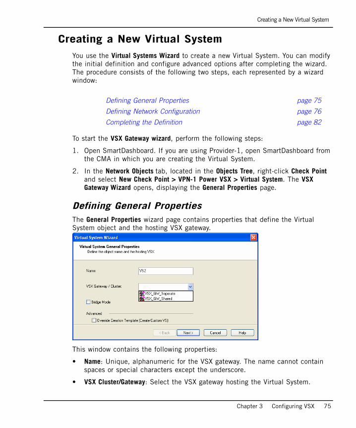
Creating a New Virtual System
Chapter 3 Configuring VSX 75
Creating a New Virtual SystemYou use the Virtual Systems Wizard to create a new Virtual System. You can modify the initial definition and configure advanced options after completing the wizard. The procedure consists of the following two steps, each represented by a wizard window:
To start the VSX Gateway wizard, perform the following steps:
1. Open SmartDashboard. If you are using Provider-1, open SmartDashboard from the CMA in which you are creating the Virtual System.
2. In the Network Objects tab, located in the Objects Tree, right-click Check Point and select New Check Point > VPN-1 Power VSX > Virtual System. The VSX Gateway Wizard opens, displaying the General Properties page.
Defining General PropertiesThe General Properties wizard page contains properties that define the Virtual System object and the hosting VSX gateway.
This window contains the following properties:
• Name: Unique, alphanumeric for the VSX gateway. The name cannot contain spaces or special characters except the underscore.
• VSX Cluster/Gateway: Select the VSX gateway hosting the Virtual System.
Defining General Properties page 75
Defining Network Configuration page 76
Completing the Definition page 82
Creating a New Virtual System
76
• Bridge Mode: Enable this option to create a Virtual System in the Bridge Mode.
• Override Creation Template: You can optionally override the creation template selected during the initial configuration of the VSX gateway. This allows you to add additional interfaces and to modify the topology and other properties.
Defining Network Configuration The Virtual System Network Configuration page allows you to define internal and external interfaces as well as the IP address topology located behind the internal interface. The process for Virtual System defining network properties varies according to the several factors:
• The VSX Gateway Creation template used to define the gateway containing the virtual system.
• Whether or not you choose to override the default VSX Gateway Creation template. This has the effect of using the Custom Configuration template.
• Whether or not you create the Virtual System in the Bridge Mode.
Use one of the following network configuration scenarios, according to your environment:
Note - The Bridge mode is not available for a Virtual System created with the Shared Interface template.
Shared Interface or Separate Interfaces page 77
Separate Interfaces in Bridge Mode page 78
Custom Configuration or Override page 79
Custom Configuration or Override in Bridge Mode page 81
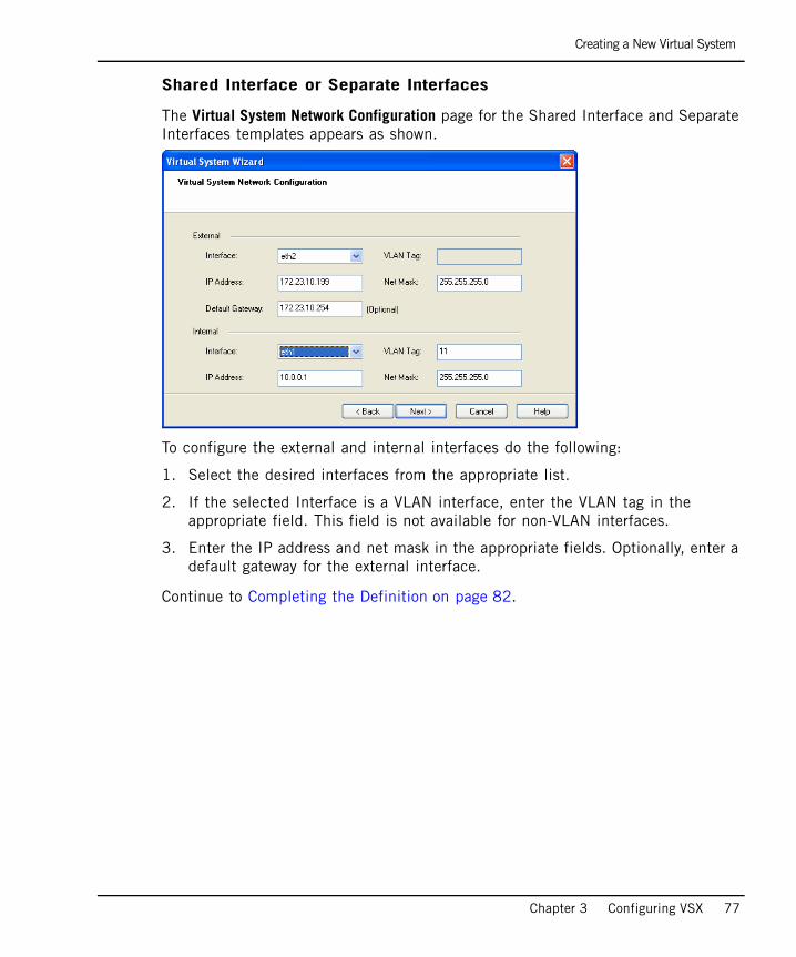
Creating a New Virtual System
Chapter 3 Configuring VSX 77
Shared Interface or Separate Interfaces
The Virtual System Network Configuration page for the Shared Interface and Separate Interfaces templates appears as shown.
To configure the external and internal interfaces do the following:
1. Select the desired interfaces from the appropriate list.
2. If the selected Interface is a VLAN interface, enter the VLAN tag in the appropriate field. This field is not available for non-VLAN interfaces.
3. Enter the IP address and net mask in the appropriate fields. Optionally, enter a default gateway for the external interface.
Continue to Completing the Definition on page 82.

Creating a New Virtual System
78
Separate Interfaces in Bridge Mode
The Virtual System Network Configuration page for the Separate Interfaces template in the Bridge Mode appears as shown.
To configure the external and internal interfaces perform the following steps:
1. Select the desired interfaces for the internal and external networks from the appropriate list.
If the selected Interface is a VLAN interface, enter the same VLAN tag in both the external and internal VLAN Tag fields. This field is not available for non-VLAN interfaces.
2. Define the topology for the internal interface as follows:
- Select Not Defined if you do not wish to define an IP address.
- Select Specific and then select a IP address definition from the list. IP address definitions can be based on object groups or predefined networks that define the topology.

Creating a New Virtual System
Chapter 3 Configuring VSX 79
3. If you wish to create a new IP address definition perform the following steps:
a. Select Specific and click New.
b. Select Group to define an object group or Network to define network properties. The appropriate window appears. Refer to the online help for details regarding either of these options.
4. If you wish to enable Layer-3 bridge interface monitoring, enable the appropriate option and enter an IP address and net mask to monitor.
Continue to Completing the Definition on page 82.
Custom Configuration or Override
If you used the Custom Configuration template when creating the VSX gateway, or if you selected the Override Creation Template option, it is necessary to manually define the network interfaces and connections. The Virtual System Network Configuration page for Custom Configuration appears as shown:
Creating a New Virtual System
80
To configure the external and internal interfaces, do the following:
1. In the interface table, define interfaces. You can add new interfaces as well as delete and modify existing interfaces.
To add an interface, click Add. The Interface Properties window opens. Select an interface from the list and define the appropriate properties. Click Help for details regarding the various properties and options.
2. Select the Main IP Address from the list. This IP address, typically that of the external interface, specifies the “real” Virtual System address used when working with NAT or VPN connections.
To make your external IP address routable, select the external interface IP address as the main IP address.
3. Define network routing as appropriate for your deployment. Some routes are automatically defined automatically based on the interface definitions.
For example, you would generally define a default gateway route leading to an external Virtual Router or to the Virtual System external interface.
To add a default route to the Routes table, click Add Default Routes and either enter the default route IP address or select the default Virtual Router. The Route Configuration windows opens. Click Help for details regarding the various properties and options.
Continue to Completing the Definition on page 82.

Creating a New Virtual System
Chapter 3 Configuring VSX 81
Custom Configuration or Override in Bridge Mode
If you used the Custom Configuration template when creating the VSX gateway, or if you selected the Override Creation Template option, and are creating a Virtual System in the Bridge Mode, you will need to manually define the network interfaces. The Virtual System Network Configuration page appears as shown.
To configure the external and internal interfaces, define interfaces and links to devices in the Interfaces table. You can add new interfaces as well as delete and modify existing interfaces.
• To add an interface, click Add. The Interface Properties window opens. Select an interface from the list and define is properties. Click Help for details regarding the various properties and options.

Creating a New Virtual System
82
Completing the DefinitionClick Next and then Finish to create the Virtual System. Please note that this may take several minutes to complete. A message appears indicating successful or unsuccessful completion of the process.
If the process ends unsuccessfully, click View Report to view the error messages. Refer to Chapter 9, “VSX Diagnostics and Troubleshooting” for further assistance.
Once you create a VSX gateway using the VSX Wizard, you can modify the topology and all other parameters using the VSX Gateway Properties window. This window also allows you to access many advanced features and options that are not available via the wizard.
Modifying a Virtual System Definition
Chapter 3 Configuring VSX 83
Modifying a Virtual System DefinitionOnce you create a Virtual System using the wizard, you can modify the topology and other properties using the Check Point Virtual System window. This window also allows you to configure many advanced features and options that are not available in the wizard.
To work with a Virtual System definition, double-click on the Virtual System object in the Object tree. The Check Point Virtual System window opens, displaying the General Properties page.
The following sections describe the various pages and properties that constitute a Virtual System definition.
In This Section
Virtual System - General Properties page 84
Virtual System - Topology page 85
Virtual System - NAT page 87
Virtual System - SmartDefense page 88
Virtual System - VPN page 88
Virtual System - Remote Access page 88
Virtual System - Authentication page 88
Virtual System - Logs and Masters page 88
Virtual System - Capacity Optimization page 89
Virtual System - Advanced page 89

Modifying a Virtual System Definition
84
Virtual System - General PropertiesThe General Properties page allows you specify the main IP address and to select the Check Point products enabled for a Virtual System.

Modifying a Virtual System Definition
Chapter 3 Configuring VSX 85
Virtual System - Topology The Topology page contains definitions for Virtual System interfaces, routes and Warp links. Based on these interface settings, VSX automatically creates routes to Virtual Devices and the VSX gateway.
Note - If you modify the topology for a specific Virtual System in a cluster environment, the cluster topology is not updated until you install a policy on that Virtual System.

Modifying a Virtual System Definition
86
• Routes:
- To add a default route to the Routes table, click Add Default Routes and either enter an IP address or select a Virtual Router. The Route Configuration windows opens. Click Help for details regarding the various properties and options.
• Interfaces: The Interfaces table defines interfaces and links to devices. You can add new interfaces as well as delete and modify existing interfaces.
- To add an interface, click Add. The Interface Properties window opens. Select the interface from the list and define the appropriate properties. Refer to “Modifying an Interface Definition” on page 113 or the online help for details regarding the various properties and options.
• Calculate topology automatically based on routing information: Enable this option to allow VSX NGX R65 to automatically calculate the network topology based on interface and routing definitions (enabled by default). VSX NGX R65 creates automatic links, or connectivity cloud objects linked to existing internal or external networks.
- This option is not available in the Bridge Mode.
- When employing dynamic routing, it is recommended to disable this option.
• VPN Domain: The VPN Domain defines the set of hosts located behind a given Virtual System that communicate via a VPN tunnel with peer Virtual Systems. These options are only available if you selected VPN in the Check Point Products section on the General Properties page.
When including a virtual device as part of a VPN connection, you must specify a VPN Domain. The domain definition specifies Virtual System interfaces that are included in the VPN. You can define a VPN Domain in one of two ways by enabling the appropriate option:
- All IP Addresses behind gateway based on topology information: Includes all hosts not located behind an external gateway cluster interface.
- Manually Defined: Includes all hosts in the selected network or group.

Modifying a Virtual System Definition
Chapter 3 Configuring VSX 87
Virtual System - NATThe NAT page allows you to configure NAT rules for packets originating from a Virtual System.
To enable and configure NAT for a Virtual System, perform the following steps:
1. Enable the Add Automatic Address Translation option.
2. Select a translation method from the list.
- Hide NAT: Hide NAT only allows connections originating from the internal network. Internal hosts can access internal destinations, the Internet and other external networks. External sources cannot initiate a connection to internal network addresses.
- Static NAT: Static NAT translates each private address to a corresponding public address.
3. If you select Hide NAT, select one of the following options:
- Hide behind Gateway hides the real address behind the VSX gateway external interface address, or
- Hide behind IP Address hides the real address behind a virtual IP address, which is a routable, public IP address that does not belongs to any real machine.
4. If you selected Static NAT, enter the static IP address in the appropriate field.
5. Select the desired VSX gateway from the Install on Gateway list.

Modifying a Virtual System Definition
88
Virtual System - SmartDefense Since VSX NGX R65 Virtual System on supports the default protection profile, this page has no configurable properties.
Virtual System - VPNThe VPN page contains a variety of configuration properties for Virtual Systems in site-to-site VPN deployments. This window is only available if the Check Point VPN product is enabled on the General Properties page.
Please refer to the online help and the VPN Administration Guide for further details regarding VPN concepts and configuration.
Virtual System - Remote AccessThe Remote Access page contains properties that govern establishing VPN connections with Remote Access clients. This window is only available if the Check Point VPN product is enabled on the General Properties page.
Please refer to the online help and the VPN Administration Guide for further details regarding VPN with Remote Access clients.
Virtual System - Authentication
The Authentication page allows you to enable several different authentication options for a VSX gateway. Please refer to Authentication on page 114 for further details.
Virtual System - Logs and Masters The Logs and Masters page allows you define logging options for a VSX gateway. Please refer to Tracking Activity with SmartView Monitor on page 123 for further details.

Deleting a Virtual System
Chapter 3 Configuring VSX 89
Virtual System - Capacity Optimization The Capacity Optimization page allows you to maximize Virtual System and VPN throughput by limiting the following connection parameters:
• Concurrent connections (Default = 15,000)
• Number of concurrent IKE negotiations (Default = 200)
• Number of concurrent VPN tunnels (Default = 200).
To raise or lower the maximum, use the arrows in the appropriate field to set the desired value. If you change the Maximum concurrent connections option, you must install a policy to the Virtual System.
Virtual System - AdvancedThese pages contain a variety of configuration options for SNMP, connection persistence and permissions to install policies. For further information regarding these options, please refer to the online help and the Firewall and SmartDefense Administration Guide.
Deleting a Virtual SystemTo delete a Virtual System, right click the appropriate Virtual System object on the Object Tree and select Delete. Click Yes in the confirmation box.
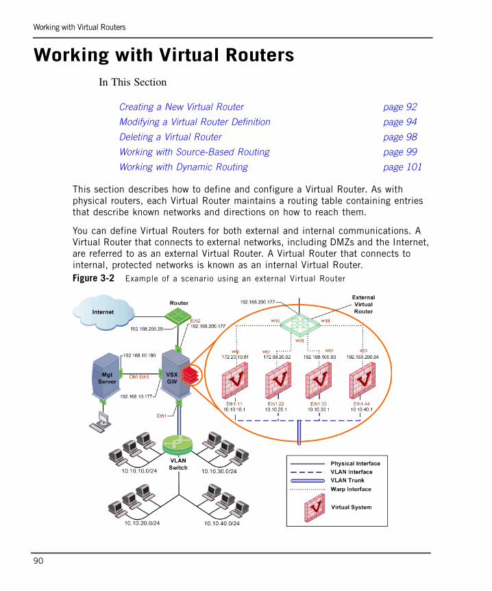
Working with Virtual Routers
90
Working with Virtual RoutersIn This Section
This section describes how to define and configure a Virtual Router. As with physical routers, each Virtual Router maintains a routing table containing entries that describe known networks and directions on how to reach them.
You can define Virtual Routers for both external and internal communications. A Virtual Router that connects to external networks, including DMZs and the Internet, are referred to as an external Virtual Router. A Virtual Router that connects to internal, protected networks is known as an internal Virtual Router.Figure 3-2 Example of a scenario using an external Virtual Router
Creating a New Virtual Router page 92
Modifying a Virtual Router Definition page 94
Deleting a Virtual Router page 98
Working with Source-Based Routing page 99
Working with Dynamic Routing page 101

Working with Virtual Routers
Chapter 3 Configuring VSX 91
Figure 3-2 presents an example of a scenario using an external Virtual Router and a internal VLAN trunk.
An external Virtual Router functions as the external gateway for Virtual Systems, allowing them to share a single secure physical interface leading to external networks and the Internet. Figure 3-3 Example of a scenario with external and internal Virtual Routers
Figure 3-3 presents an example of a scenario using both external and internal Virtual Routers. In this scenario, VSX creates Warp interfaces between the Virtual Systems and both Virtual Routers. Note that the external Virtual System interfaces are defined as unnumbered interfaces.
An internal Virtual Router typically connects with one interface leading to internal networks through a switch with additional Warp Links leading to other Virtual Systems located in the VSX gateway.
The following sections describe how to create and configure Virtual Routers. The example screen shots refer to the topology illustrated in Figure 3-3. After creating a new Virtual Router you then add new interfaces to the Virtual Systems that connect to the newly created Virtual Router.
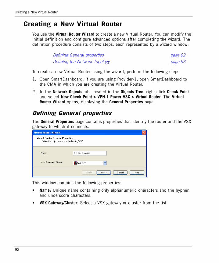
Creating a New Virtual Router
92
Creating a New Virtual RouterYou use the Virtual Router Wizard to create a new Virtual Router. You can modify the initial definition and configure advanced options after completing the wizard. The definition procedure consists of two steps, each represented by a wizard window:
To create a new Virtual Router using the wizard, perform the following steps:
1. Open SmartDashboard. If you are using Provider-1, open SmartDashboard to the CMA in which you are creating the Virtual Router.
2. In the Network Objects tab, located in the Objects Tree, right-click Check Point and select New Check Point > VPN-1 Power VSX > Virtual Router. The Virtual Router Wizard opens, displaying the General Properties page.
Defining General propertiesThe General Properties page contains properties that identify the router and the VSX gateway to which it connects.
This window contains the following properties:
• Name: Unique name containing only alphanumeric characters and the hyphen and underscore characters.
• VSX Gateway/Cluster: Select a VSX gateway or cluster from the list.
Defining General properties page 92
Defining the Network Topology page 93
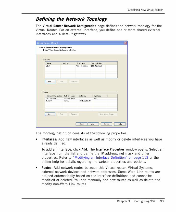
Creating a New Virtual Router
Chapter 3 Configuring VSX 93
Defining the Network TopologyThe Virtual Router Network Configuration page defines the network topology for the Virtual Router. For an external interface, you define one or more shared external interfaces and a default gateway.
The topology definition consists of the following properties:
• Interfaces: Add new interfaces as well as modify or delete interfaces you have already defined.
To add an interface, click Add. The Interface Properties window opens. Select an interface from the list and define the IP address, net mask and other properties. Refer to “Modifying an Interface Definition” on page 113 or the online help for details regarding the various properties and options.
• Routes: Add network routes between this Virtual router, Virtual Systems, external network devices and network addresses. Some Warp Link routes are defined automatically based on the interface definitions and cannot be modified or deleted. You can manually add new routes as well as delete and modify non-Warp Link routes.

Modifying a Virtual Router Definition
94
• Add Default Route: Define the default gateway as an IP address or Virtual System.
• Advanced Routing: Configure source-based routing rules. Refer to “Working with Source-Based Routing” on page 99 for details.
Modifying a Virtual Router DefinitionOnce you create a Virtual Router using the wizard, you can modify the topology and other properties using the Check Point Virtual Router window. This window also allows you to configure many advanced features and options that are not available in the wizard.
To work with a Virtual Router definition, double-click on the Virtual Router object in the Object tree. The Check Point Virtual Router window opens, displaying the General Properties page.
The following sections describe the various pages and properties that constitute a Virtual Router definition
Virtual Router - General Properties page 95
Virtual Router - Topology page 96
Virtual Router - SmartDefense page 97
Virtual Router - Logs and Masters page 97
Virtual Router - Capacity Optimization page 97
Virtual Router - Advanced page 97
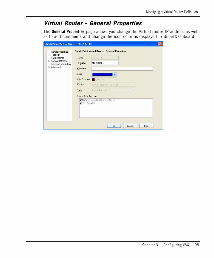
Modifying a Virtual Router Definition
Chapter 3 Configuring VSX 95
Virtual Router - General PropertiesThe General Properties page allows you change the Virtual router IP address as well as to add comments and change the icon color as displayed in SmartDashboard.
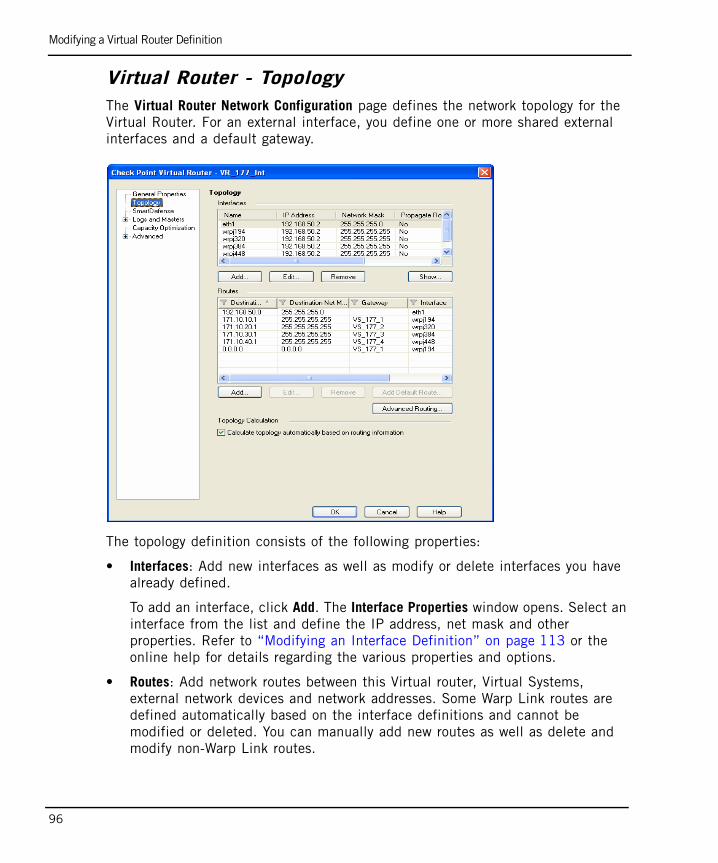
Modifying a Virtual Router Definition
96
Virtual Router - TopologyThe Virtual Router Network Configuration page defines the network topology for the Virtual Router. For an external interface, you define one or more shared external interfaces and a default gateway.
The topology definition consists of the following properties:
• Interfaces: Add new interfaces as well as modify or delete interfaces you have already defined.
To add an interface, click Add. The Interface Properties window opens. Select an interface from the list and define the IP address, net mask and other properties. Refer to “Modifying an Interface Definition” on page 113 or the online help for details regarding the various properties and options.
• Routes: Add network routes between this Virtual router, Virtual Systems, external network devices and network addresses. Some Warp Link routes are defined automatically based on the interface definitions and cannot be modified or deleted. You can manually add new routes as well as delete and modify non-Warp Link routes.
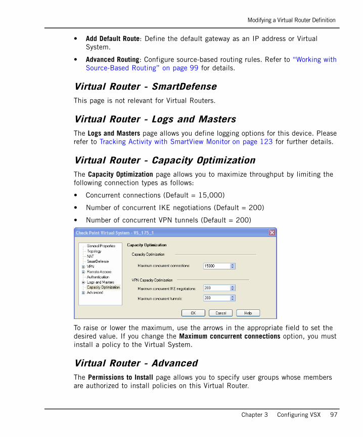
Modifying a Virtual Router Definition
Chapter 3 Configuring VSX 97
• Add Default Route: Define the default gateway as an IP address or Virtual System.
• Advanced Routing: Configure source-based routing rules. Refer to “Working with Source-Based Routing” on page 99 for details.
Virtual Router - SmartDefense This page is not relevant for Virtual Routers.
Virtual Router - Logs and Masters The Logs and Masters page allows you define logging options for this device. Please refer to Tracking Activity with SmartView Monitor on page 123 for further details.
Virtual Router - Capacity Optimization The Capacity Optimization page allows you to maximize throughput by limiting the following connection types as follows:
• Concurrent connections (Default = 15,000)
• Number of concurrent IKE negotiations (Default = 200)
• Number of concurrent VPN tunnels (Default = 200).
To raise or lower the maximum, use the arrows in the appropriate field to set the desired value. If you change the Maximum concurrent connections option, you must install a policy to the Virtual System.
Virtual Router - AdvancedThe Permissions to Install page allows you to specify user groups whose members are authorized to install policies on this Virtual Router.

Deleting a Virtual Router
98
Deleting a Virtual RouterYou cannot delete a Virtual Router if it is still connected to a Virtual System. Remove all Virtual Router connections before deleting.
To delete a Virtual Router, right click the appropriate Virtual Router object on the Object Tree and select Delete. Click Yes in the confirmation box.

Working with Source-Based Routing
Chapter 3 Configuring VSX 99
Working with Source-Based RoutingSource-based routing directs traffic to a specific destination based on the source IP address or a combination of the source and destination IP addresses. Rules defining Source-based routing take precedence over ordinary destination-based routing rules.
This section describes how to configure sourced-based routing rules when working in a VSX environment. The procedures for defining source-based rules are the same for Virtual Routers in both VSX gateways and VSX clusters. Figure 3-4 Routing scenario incorporating source-based routing

Working with Source-Based Routing
100
Defining Source-Based Routing RulesYou define Source-based Routing rules from the Topology page in the Virtual Router definition window.
To define source-based routing rules, perform the following steps:
1. Open the appropriate internal Virtual Router definition in SmartDashboard and select the Topology page. The Advanced Routing Rules window opens.
Note that the highlighted rule is based on both a source and destination address, as compared to the preceding rules, which are based on a source address only.
2. Click Add to define a new rule or Edit to modify an existing rule. The Add/Edit Route Rule window appears.
Define the following properties as required:
- Source IP Address and Net Mask
- Destination IP Address and Net Mask (optional)
- Next Hop Gateway: Select a Virtual System from the list.

Working with Dynamic Routing
Chapter 3 Configuring VSX 101
Working with Dynamic RoutingThis section presents procedures for configuring dynamic routing for Virtual Systems and Virtual Routers. Virtual Devices can communicate and distribute routes amongst themselves using dynamic routing protocols.
You configure dynamic routing separately for each Virtual System and/or Virtual Router, each of which has its own dynamic routing daemon and configuration file. You also configure dynamic routing separately on each cluster member.
Enabling Dynamic RoutingTo enable dynamic routing, perform the following steps:
1. Enable dynamic routing for the appropriate Virtual System or Virtual Router by executing the following commands from the VSX gateway in the expert mode:
a. vsx set <vs_id>, where <vs_id> is the device context ID
b. drouter enable <vs_id> (enables dynamic routing)
c. drouter start <vs_id> (starts the dynamic routing daemon)
Configuring Dynamic RoutingTo configure dynamic routing, perform the following steps:
1. Execute the router command.
2. Configure dynamic routing according to your requirements. Refer to the SecurePlatform Pro & Advanced Routing Command Line Interface Administration Guide for details.
Disabling Dynamic RoutingTo enable dynamic routing, perform the following steps:
1. Execute the following commands from the VSX gateway command line:
a. drouter stop <vs_id> (stops the dynamic routing daemon)
b. drouter disable <vs_id> (disables dynamic routing)
Checking Dynamic Routing StatusTo check whether dynamic routing is active, execute the drouter stat <vs_id> command from the VSX gateway command line. A message appears indicating whether or not dynamic is enabled.

Working with Virtual Switches
102
Working with Virtual Switches
Virtual Switches provide level-2 connectivity between Virtual Systems and internal or external networks. This section describes how to define and configure a Virtual Switch. As with physical switches, each Virtual Switch maintains a forwarding table containing entries that describe known networks and directions for reaching them.
You can define Virtual Switches for external and internal communications. Figure 3-5 Example of a scenario using Virtual Switches
Figure 3-5 shows a typical deployment using a Virtual Switch for external connections and a VLAN trunk leading to the internal, protected network.
Adding Virtual Switches page 103
Modifying Virtual Switches page 104
Deleting a Virtual Switch page 106

Adding Virtual Switches
Chapter 3 Configuring VSX 103
Adding Virtual SwitchesYou use the Virtual Switch Wizard to create a new Virtual Switch. You can modify the initial definition and configure advanced options after completing the wizard. The definition procedure consists of two steps, each represented by a separate wizard window:
To create a new Virtual Switch using the wizard, perform the following steps:
1. Open SmartDashboard. If you are using Provider-1, open SmartDashboard from the CMA in which you are creating the Virtual Switch.
2. In the Network Objects tab, located in the Objects Tree, right-click Check Point and select New Check Point > VPN-1 Power VSX > Virtual Switch. The Virtual Router Wizard opens, displaying the General Properties page. The Virtual Switch Wizard opens.
Defining the General PropertiesThe General Properties page contains properties that identify the Virtual Switch and the VSX gateway or cluster to which it connects.
This window contains the following properties:
• Name: Unique name containing only alphanumeric characters, the hyphen and underscore characters.
• VSX Gateway/Cluster: Select a VSX gateway or cluster from the list.

Modifying Virtual Switches
104
Defining the Network ConfigurationThe Network Configuration page defines the Virtual Switch interface.
A Virtual Switch has one interface. Click Add and select the interface from the list. If applicable, enter a VLAN tag in the appropriate field.
Modifying Virtual SwitchesOnce you create a Virtual Switch using the wizard, you can modify the topology and other properties using the Check Point Virtual Switch window. This window also allows you to configure advanced features and options that are not available in the wizard.
To work with a Virtual Switch definition, double-click the Virtual Switch object in the Object tree. The Check Point Virtual Switch window opens, displaying the General Properties page.
The following sections describe the various pages and properties that constitute a Virtual Switch definition.
Note - You can define a Virtual Switch with no interfaces for the sole purpose of communication between Virtual Systems.

Modifying Virtual Switches
Chapter 3 Configuring VSX 105
General PropertiesThe General Properties page allows you to add comments and change the icon color as displayed in SmartDashboard.
TopologyThe Topology page defines Virtual Switch interfaces. You can only modify the single defined interface. Warp interfaces cannot be modified from this window.
To add an interface, click Add. The Interface Properties window opens. Select an interface from the list and define the IP address, net mask and other properties as required. Refer to “Modifying an Interface Definition” on page 113 or the online help for details regarding the various properties and options.
Deleting a Virtual Switch
106
Deleting a Virtual SwitchYou must remove all Virtual System connections before attempting to delete a Virtual Switch.
To delete a Virtual Switch, right click the appropriate Virtual Switch object in the Object Tree and select Delete. Click Yes in the confirmation box.

Working with Interface Definitions
Chapter 3 Configuring VSX 107
Working with Interface DefinitionsAll VSX gateways and virtual objects contain at least one interface definition. Typically, you define the interfaces during the process of configuring the topology for a given object. Warp interfaces, however, are created automatically based on virtual object definitions and their topology. You cannot modify or delete a Warp interface.
Adding a New InterfaceThe procedure and options for defining an interface vary according to the object and the network topology. Please note that some properties and pages are not available for certain interface definitions.
To add a new interface, perform the following steps:
1. On the Topology page, click Add.
2. If a connection options list appears as shown below, choose the desired connection for this interface.
3. The Interface Properties window opens. Configure the appropriate properties as described in the following sections.

Adding a New Interface
108
Configuring Connection Properties - GeneralThe General tab defines the network connections associated with an interface.
One or more of the following properties may appear.
• Interface: Select a physical interface from the list (physical interfaces only).
• Leads to: Select a Virtual Router or Virtual Switch from the list (Warp links to Virtual Routers and Virtual Switches).
• VLAN Tag: VLAN tag associated with the defined interface.
• IP Address and Net Mask: IP address and net mask of the device associated with the interface.
• Propagate route to adjacent Virtual Devices: Enable to “advertise” the associated device to neighboring devices, thereby enabling connectivity between them. See“Route Propagation” on page 47 for details.
• MTU: Maximum transmission unit size in bytes (default = 1,500)
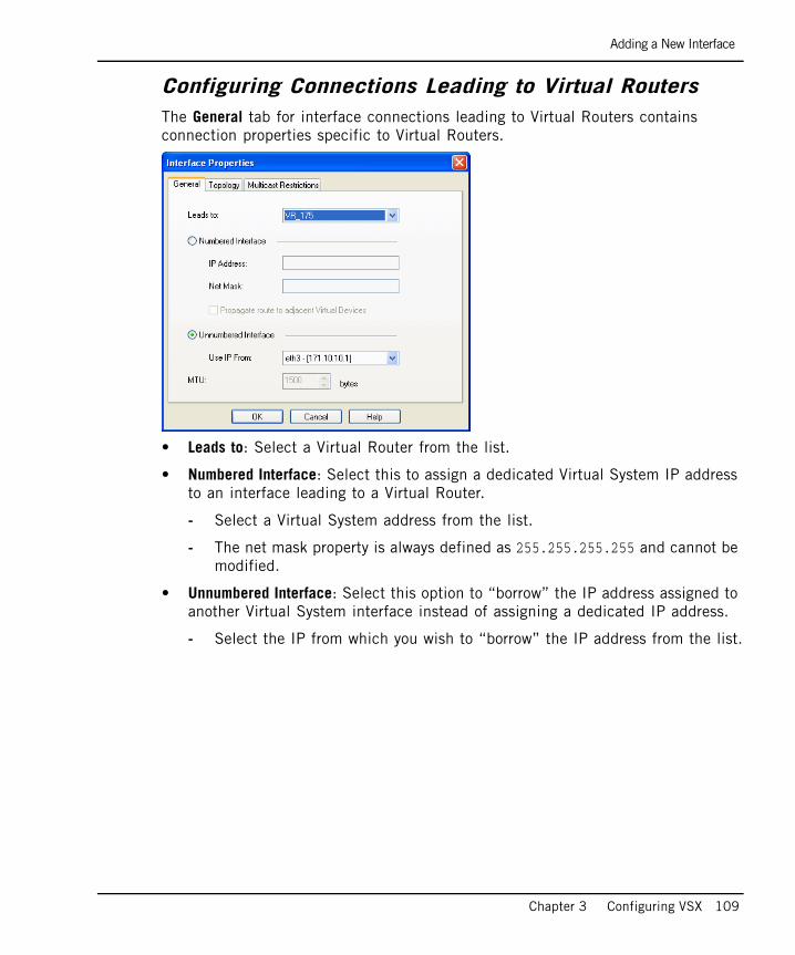
Adding a New Interface
Chapter 3 Configuring VSX 109
Configuring Connections Leading to Virtual RoutersThe General tab for interface connections leading to Virtual Routers contains connection properties specific to Virtual Routers.
• Leads to: Select a Virtual Router from the list.
• Numbered Interface: Select this to assign a dedicated Virtual System IP address to an interface leading to a Virtual Router.
- Select a Virtual System address from the list.
- The net mask property is always defined as 255.255.255.255 and cannot be modified.
• Unnumbered Interface: Select this option to “borrow” the IP address assigned to another Virtual System interface instead of assigning a dedicated IP address.
- Select the IP from which you wish to “borrow” the IP address from the list.

Adding a New Interface
110
Configuring Interface TopologyFor some interface types, you can directly modify some or all of the following topology properties:
• External: The interface leads to external networks or to the Internet
• Internal: The interface leads to internal networks and/or a DMZ and includes the following properties:
- Not Defined: IP routing is not defined for this device.
- Network: Routing is defined by the IP and net mask defined in General Properties.
- Specific: Routing is defined by a specific network or network group.
- Interface leads to DMZ: Defines an interface as leading to a DMZ, which Isolates a vulnerable, externally accessible resource from the rest of an protected, internal network

Adding a New Interface
Chapter 3 Configuring VSX 111
Configuring Anti-SpoofingAttackers can gain access to protected networks by falsifying or “spoofing” a trusted source IP address with high access privileges. It is important to configure anti-spoofing protection for VSX gateways and Virtual Systems, including internal interfaces. You can configure anti-spoofing for an interface, provided that the topology for the interface is properly defined.
If you are using dynamic routing, disable the Calculate topology automatically based on routing information option, and manually configure the topology of the Virtual System.
To enable anti-spoofing for an interface, enable the Perform Anti-Spoofing based on interface topology option on the Topology tab in the Interface Properties window. Select a tracking option as appropriate.
Configuring Multicast RestrictionsIP multicasting applications send one copy of each datagram (IP packet) and address it to a group of computers that wish to receive it. Multicast restrictions allow you to define rules that block outbound datagrams from specific multicast groups (IP address ranges). You can define multicast access restrictions for physical and Warp interfaces in a VSX environment.
To enable multicast restrictions, perform the following steps:
1. Enable the Drop multicast packets by the following conditions option on the Multicast Restrictions tab in the Interface Properties window.

Adding a New Interface
112
2. Select one of the following restriction types:
- Drop multicast packets whose destination is in the list
- Drop all multicast packets except those whose destination is in the list
3. Click Add to add a multicast address range. The Multicast Address Range Properties window opens.
4. Define an IP address Range or a Single IP Address in the 224.0.0.0 to 239.255.255.255 range.
5. Select a tracking option.
6. Close the window and save the definition.
7. Add a rule to the Rule Base that allows traffic for the specified multicast groups and install the policy.
Modifying an Interface Definition
Chapter 3 Configuring VSX 113
Modifying an Interface DefinitionThis sections presents procedures for modifying existing interface definitions and related features.
Selecting and Opening an Existing InterfaceInterfaces definitions are always associated with a Virtual Gateway or a Virtual System definition. To work with an existing interface definition, double click the desired interface in the Interfaces section. The Interface Properties window opens. Define interface properties as described in “Adding a New Interface” on page 107.
Deleting an InterfaceTo delete an interface, click Remove on the object Topology page.
Authentication
114
AuthenticationIn This Section
Supported Authentication SchemesAuthentication schemes employ user names and passwords to identify valid users. Some schemes are maintained locally, storing user names and passwords on the VSX gateway, while others store authentication information on an external authentication server. Some schemes, such as SecurID, are based on providing a one-time password.
All of the schemes can be used with users defined on an LDAP server. For additional information on configuring VPN-1 to integrate with an LDAP server, refer to the SmartDirectory (LDAP) and User Management section in the SmartCenter Administration Guide.
Check Point Password VSX stores a static password for each user in the management server database. No additional software is required.
Operating System PasswordVSX can authenticate users by means of a user name and password defined on the management server operating system. You can also use passwords stored in a Windows domain. No additional software is required.
RadiusRemote Authentication Dial In User Service (RADIUS) is an external, server-based authentication protocol that provides authentication services using the UDP protocol.
Supported Authentication Schemes page 114
Client/Session Authentication page 120

Supported Authentication Schemes
Chapter 3 Configuring VSX 115
TACACS, TACACS+Terminal Access Controller Access Control System (TACACS) is an external, server-based authentication protocol that provides verification services using the TCP protocol. TACACS+ is an enhanced version of the TACACS that supports additional types or authentication requests and response codes.
SecurIDSecurID requires users to possess a token authenticator and to supply a password. Token authenticators generate one-time passwords that are synchronized to an RSA ACE/server. Hardware tokens are key-ring or credit card-sized devices, while software tokens reside on the PC or device from which the user wants to authenticate. All tokens generate a random, one-time use access code that changes approximately every minute. When a user attempts to authenticate to a protected resource, the one-time use code must be validated by the ACE/server.
Configuring RADIUS or TACACS/TACACS+
116
Configuring RADIUS or TACACS/TACACS+Two options are available for enabling connectivity between Virtual Systems and external authentication servers:
• Shared: Servers are accessible from VSX gateways and clusters
• Private: Servers are accessible from Virtual Systems
Shared
When the shared option is configured, all authentication servers are accessible by all Virtual Systems through the VSX gateway. This is the default option.
• To configure the shared option, use the database tool GuiDBedit to set the shared_external_server property to TRUE (default setting).
• The Virtual Systems use the IP address of the VSX gateway. Therefore, connections to external servers have the VSX machine’s IP address as their source address, a unique IP address for each cluster member. Virtual Systems on the same cluster member have identical source addresses when accessing the external management server.
• Verify that the Authentication Server is located on the same network segment as the VSX gateway.
• Members of the cluster must not perform hide NAT on the external server service. To prevent Hide NAT:
1. On the management server, open the /opt/CPvsxngxcmp-R65/lib/table.def file for editing.
2. To the no_hide_services_ports table, add the service of the authentication scheme you wish to use. For example UDP 5500 for SecurID. The line should read:
3. Reinstall the policy on the Virtual System.
Private
When the private option is configured, authentication servers are accessed directly by the Virtual System.
• The Virtual system and the authentication server are located on the same network segment.
no_hide_services_ports = { <500, 17>, <259, 17>, <1701, 17>, <123, 17>, <5500,17> };

Configuring RADIUS or TACACS/TACACS+
Chapter 3 Configuring VSX 117
• Connections to the external authentication server use the Virtual System’s cluster IP address as the source address.
• To configure the private option, use the database tool GUIDBedit to set the shared_external_server property to FALSE.
• Once the private option has been configured, it is not possible for the Virtual System to connect to other authentication servers in the VSX management network unless an explicit path is created through a Virtual Router or Virtual Switch.
• There is no need to edit the table.def file.
Configuring SecurID ACE/Server
118
Configuring SecurID ACE/ServerThere are two options available for enabling connectivity between Virtual Systems and a SecurID ACE/Server:
• Shared: Servers are accessible from VSX gateways and clusters
• Private: Servers are accessible from Virtual Systems
In both instances, the SecurID ACE/Server sends a shared key (called a “node secret”) to its peer ACE/Clients. This key is unique per IP address, and is sent once for each IP address.
Shared
• To configure the shared option, use the database tool GUIDBedit to set the shared_external_server property to TRUE.
• Members of the cluster must not perform Hide NAT on the external server service. To prevent Hide NAT, perform the following steps:
1. On the management server, open the /opt/CPvsxngxcmp-R65/lib/table.def file for editing.
2. Add the UDP 5500 service to the no_hide_services_ports table. The line should read as follows:
3. Reinstall the policy on the Virtual Systems.
• To generate an sdconf.rec file, perform the following procedure on the ACE/Server.
1. Generate the sdconf.rec file with the IP address of the VSX gateway: VS(0).
2. Copy the sdconf.rec file to the appropriate cluster member.
A. When a Virtual System connects to a VSX gateway at VS(0), place the sdconf.rec in the /ace/var directory. Create this directory if it does not exist.
B. In all other cases, place sdconf.rec in $FWDIR/CTX/CTX000X/conf.
Note - Users cannot authenticate to a Virtual System using SecurID when SNX and SecureClient are active.
no_hide_services_ports = { <500, 17>, <259, 17>, <1701, 17>, <123, 17>, <5500,17> };
Configuring SecurID ACE/Server
Chapter 3 Configuring VSX 119
Private
When using the private option for accessing external servers, all the members use the same cluster IP address as the source address for connections to the ACE/Server.
• To configure the private option, use the database tool GUIDBedit to set the shared_external_server property to FALSE.
• After the first connection that uses SecurID authentication, the ACE Server creates a shared key called securid. This “node secret” key is created only once, and sent to the $FWDIR/CTX/CTX000X/conf directory of the active cluster member.
• To make this shared key available to the other member gateways, manually copy the “node secret” key from the first gateway. (The ACE/Server will not recreate the key.)
• To generate an sdconf.rec file, perform the following procedure on the ACE/Server.
1. Generate the sdconf.rec file with the cluster IP of the Virtual System.
2. Copy the sdconf.rec file to the relevant cluster member.
A. When a Virtual System connects to a VSX gateway at VS(0), place the sdconf.rec in the /ace/var directory. Create this directory if it does not exist.
B. In all other cases, place sdconf.rec in $FWDIR/CTX/CTX000X/conf.

Client/Session Authentication
120
For Both Shared and Private Options on SecureID Connections
• In order that the active cluster member uses the cluster IP address as part of the hash performed on securID traffic, perform the following steps on all cluster members:
1. Create a file named /$FWDIR/CTX/CTX<VSID>/conf/sdopts.rec
2. Enter the client IP address:
3. Perform cpstop/cpstart.
• Perform the following procedure on all cluster members:
1. Open the /etc/services file for editing.
2. Add the following lines:
The Effect of Upgrading on Authentication Processes• An existing Virtual System that has been upgraded to the current version,
receives the default settings for authentication with external servers.
• If the Virtual System was originally created on a management server located on the same network segment as the external authentication server, connectivity may be lost until the “private” option is enabled.
Client/Session AuthenticationVSX NGX R65 offers the following client/session authentication options:
• Client authentication over TELNET (on port 259)
• Client authentication over HTTP/HTTPS (on port 900)
For a complete description of these features please refer to the Firewall and SmartDefense Administration Guide -> Network Access -> Authentication and the Firewall and SmartDefense Administration Guide.
CLIENT_IP=<Virtual System cluster IP>
securid 5500/udpsecuridprop 5510/tcp

Working with Network Address Translation
Chapter 3 Configuring VSX 121
Working with Network Address TranslationThis section describes the process for using Network Address Translation (NAT) in a VSX deployment. The procedures described in this section assume that the reader is familiar with NAT concepts and their implementation in Check Point products. For more detailed information, refer to the online help or the Network Address Translation chapter in the Firewall and SmartDefense Administration Guide.
VSX NGX R65 supports NAT for Virtual Systems much in the same manner as a physical firewall. When a NAT enabled (Static or Hide) Virtual System connects to a Virtual Router, the translated routes are automatically forwarded to the appropriate Virtual Router.
Configuring NATYou configure NAT using the NAT page in the Virtual System window. Hide or Static NAT addresses configured in this manner are automatically forwarded to the Virtual Router to which the Virtual System is connected. Alternatively, you can manually add NAT routes on the Topology page in the Virtual Router window.
Configuring NAT
122
To enable and configure NAT for a Virtual System, perform the following steps:
1. Enable the Add Automatic Address Translation option.
2. Select a translation method from the list.
- Hide NAT: Hide NAT only allows connections originating from the internal network. Internal hosts can access internal destinations, the Internet and other external networks. External sources cannot initiate a connection to internal network addresses.
- Static NAT: Static NAT translates each private address to a corresponding public address.
3. If you select Hide NAT, select one of the following options:
- Hide behind Gateway hides the real address behind the VSX gateway external interface address. This is equivalent to hiding behind the address 0.0.0.0, or
- Hide behind IP Address hides the real address behind a virtual IP address, which is a routable, public IP address that does not belongs to any real machine.
4. If you selected Static NAT, enter the static IP address in the appropriate field.
5. Select the desired VSX gateway from the Install on Gateway list.
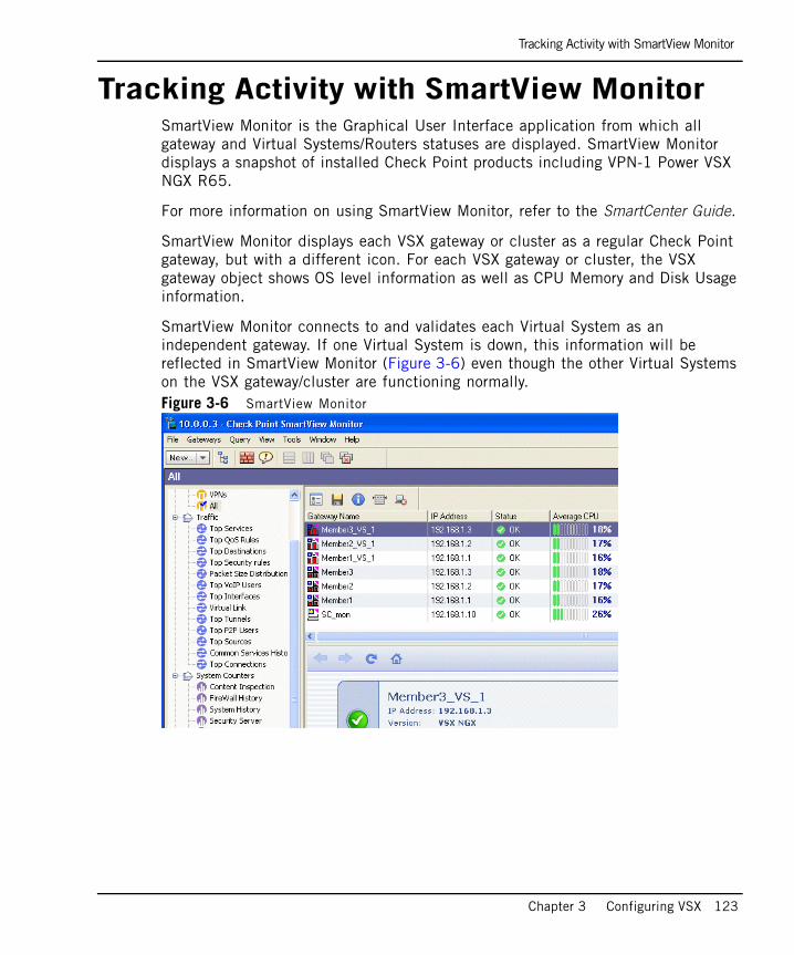
Tracking Activity with SmartView Monitor
Chapter 3 Configuring VSX 123
Tracking Activity with SmartView MonitorSmartView Monitor is the Graphical User Interface application from which all gateway and Virtual Systems/Routers statuses are displayed. SmartView Monitor displays a snapshot of installed Check Point products including VPN-1 Power VSX NGX R65.
For more information on using SmartView Monitor, refer to the SmartCenter Guide.
SmartView Monitor displays each VSX gateway or cluster as a regular Check Point gateway, but with a different icon. For each VSX gateway or cluster, the VSX gateway object shows OS level information as well as CPU Memory and Disk Usage information.
SmartView Monitor connects to and validates each Virtual System as an independent gateway. If one Virtual System is down, this information will be reflected in SmartView Monitor (Figure 3-6) even though the other Virtual Systems on the VSX gateway/cluster are functioning normally.Figure 3-6 SmartView Monitor

Tracking Activity with SmartView Monitor
124
125
Chapter 4Using VSX With Provider-1
In This Chapter
This chapter presents concepts and procedures for managing a VSX deployment using Provider-1 or SiteManager-1. This chapter also discusses the VSX and Provider-1 license bundles and associated subjects.
This chapter assumes that the reader is familiar with the Provider-1 product, its conceptual framework, procedures, and user interface. Accordingly, only those procedures that are specific to VSX deployments are discussed. For further information regarding Provider-1, please refer to the Provider-1/SiteManager-1 Administration Guide and the online help.
For the purposes of the discussion in this chapter, all procedures and references to Provider-1 are applicable to both Provider-1 and SiteManager-1, unless otherwise indicated.
Overview page 126
Licensing VSX with Provider-1 page 127
VSX Provisioning Overview page 133
Defining Multi-Domain Servers (MDSs) page 134
Defining Provider-1 Customers and CMAs page 137
Working with Virtual Devices page 145

Overview
126
OverviewCheck Point Provider-1 is a centralized security management solution that addresses the unique requirements of service providers and large enterprises. By using Provider-1, administrators can centrally manage multiple independent networks, often belonging to different customers, divisions, or branches.
The Multi-Domain Server (MDS) is a central management server that hosts the network management and security policy databases for these networks. Each independent domain is represented by a Customer Management Add-On (CMA), which provides the full functionality of a SmartCenter server. Each CMA can host Virtual Systems, Virtual Routers and Virtual Switches as well as physical Check Point gateways. We recommend that you manage each VSX gateway with its own CMA. Figure 4-1 Provider-1 management model
The CMA that manages a VSX gateway or cluster is known as a Main CMA. You can host multiple gateways and/or clusters on one MDS. We recommend, however, that you manage each gateway and cluster with its own main CMA. Virtual Systems belonging to a given customer can be distributed amongst multiple VSX gateways and clusters.
The Multi-Domain GUI (MDG) is a centralized management solution that allows administrators to manage customers, CMAs and the Provider-1 environment. Each CMA uses its own instance of SmartDashboard, which is accessible only via the MDG, to provision its virtual devices and physical gateways, as well as to manage their security policies.
Licensing VSX with Provider-1
Chapter 4 Using VSX With Provider-1 127
Licensing VSX with Provider-1In This Section
Check Point software is activated with a license key. To obtain a license key, register the certificate key (that appears on the back of the software media pack) with the Check Point User Center. The certificate key is used to generate a license key for the products that you are either evaluating or purchasing.
To purchase the required Check Point products, contact your reseller. Check Point software that has not yet been purchased functions for 15 days only.
Provider-1 LicensesProvider-1 licenses are associated with the IP address of the licensed entity. Multi-Domain Server (MDS) licenses are based on the MDS type.
• MDS Manager License: This license covers the administrator access point to the Provider-1 environment and is bound to the MDS manager IP address. The Multi-Domain GUI (MDG) can only connect to MDS machines having a valid manager license.
• MDS Container License: This license covers the container hosting CMAs running on an MDS machine. A container license is bound to the MDS container IP address and covers a specified maximum number of CMAs. Multiple container licenses can be combined on a given MDS container to cover up to a maximum of 250 CMAs.
• MDS Combined Manager and Container License: This license covers an MDS machine that functions both as a container and manager. A combined manager and container license is bound to the IP address of the MDS. SiteManager-1 licenses are available only for a combined manager and container MDS.
Provider-1 Licenses page 127
VSX Gateway/Cluster Member Licenses page 128
VSX/CMA Bundle Licenses page 129
Upgrading Licenses page 131
The Trial Period page 131
License Violations page 132
For More Information page 132

VSX Gateway/Cluster Member Licenses
128
• CMA License: Each individual CMA requires its own license, bound to its IP address. CMA licenses cover a predefined number of enforcement points (Virtual Systems and/or physical Check Point gateways). CMA licenses are available for quantities of one, two or four enforcement points as well as an unlimited license covering an unlimited number of enforcement points.
Individual CMA licenses are recommended for mixed networks consisting of both Virtual Systems and physical Check Point gateways. V
• CMA Pro: CMA Pro Add-on licenses, which enable additional management features at the CMA level, can be purchased in bulk and are called Pro Add-ons for MDS.
• Multi-Domain Log Manager (MLM): This is a comprehensive license that enables real-time logging, tracking and log management for a predefined number of Customer Log Modules (CLMs) hosted on a dedicated MLM server. MLM licences are available in packs of 10, 25, 50, 100 and 250. This license is bound to the MLM server IP address.
• Customer Log Module License: This license is intended for a single customer with log files hosted on the container MDS only. The license is bound to the CLM IP address. Individual CLM licenses are not required for CLMs hosted on an MLM server.
You can import Provider-1 licenses can using the Check Point command line licensing tool or the MDG. For additional information, refer to the R65 Provider-1/SiteManager-1 Administration Guide.
VSX Gateway/Cluster Member LicensesLike physical gateways, each individual VSX gateway or cluster member requires its own license, bound to the gateway or cluster member IP address. Each gateway/cluster license covers a predefined number of Virtual Systems (10, 25, 50, 100 and 250) and these licenses are cumulative. Gateway licenses are required in addition to Provider-1 licenses.

VSX/CMA Bundle Licenses
Chapter 4 Using VSX With Provider-1 129
VSX/CMA Bundle LicensesVSX/CMA bundle licenses are a cost-effective solution for purchasing Provider-1 CMA licenses that allow you to manage a combination of multiple CMAs and multiple Virtual Systems. Bundle licenses cover a predefined number of CMAs and Virtual Systems and are available in packs of 10, 25, 50, 100 and 250.
Each license bundle allows you to manage the following items, according to its limit:
• One Main CMA
• Up to (10, 25, 50, 100 or 250) customer CMAs
• Up to (10, 25, 50, 100 or 250) Virtual Systems
A bundle license allows you to manage any combination of CMAs and Virtual Systems, providing that the total does not exceed the license limit. Each CMA can host any number of Virtual Systems up to the license limit. For example, you can define any of the following combinations with one 10 pack bundle license:
• One main CMA and 10 customer CMAs containing one Virtual System each
• One main CMA and one customer CMA containing 10 Virtual systems
• One main CMA, one CMA containing four Virtual Systems and three CMAs, each containing two Virtual Systems
In addition to the VSX/CMA bundle license, you must purchase and install MDS licenses for each MDS and VSX gateway/cluster licenses for the required number of Virtual Systems. Furthermore, if you are using customer logging, you must purchase the appropriate MLM or CLM licenses.
Bundle License Packs are CumulativeThe maximum number of CMAs and Virtual Systems covered by your license is equal to the sum of all bundle license packs installed. For example, if you purchase two 10 license packs and one 50 license pack, you can define up to three main CMAs, 70 customer CMAs and 70 Virtual Systems. As with individual license packs, you can distribute the Virtual Systems amongst CMAs so long as the cumulative total of CMAs and Virtual Systems does not exceed the maximum.
Note - Virtual Routers and Virtual Switches do not require licenses. There is no limit to the number that you can define.

VSX/CMA Bundle Licenses
130
Limitations of VSX/CMA Bundle Licenses• Bundle licenses only cover Virtual Systems. If you wish to mix physical devices
(VPN-1 gateways, etc.) and Virtual Systems on one CMA, you must also add the appropriate regular CMA licenses.
- Virtual Systems installed on a mixed CMA do not use any license “slots” from a regular license. Similarly, physical devices do not use Virtual System license “slots”.
• Bundle licenses cannot be installed on a system using Provider-1 Enterprise Edition CMAs.
High Availability LicensesProvider-1 supports management high availability. By installing a High Availability VSX-CMA bundle license on a second MDS machine, the specified number of Virtual Systems can be hosted by secondary CMAs. The capabilities and limitations of this license are similar to those of the regular VSX/CMA bundle.
Upgrading Licenses
Chapter 4 Using VSX With Provider-1 131
Upgrading LicensesThe license upgrade procedure can be performed if you have purchased any of the Enterprise Software Subscription services.
License upgrade fails for products and accounts for which you do not have software subscriptions. To manage your accounts, licenses, and Enterprise Support Programs coverage (under Support Programs), log in to: http://usercenter.checkpoint.com. License upgrade is performed by means of a tool that automatically upgrades both locally and centrally managed licenses.
Using the tool, you can upgrade all licenses in the entire managed system. License upgrade can also be performed manually, per license, in the User Center. For instructions, refer to the guide in the User Center at: https://usercenter.checkpoint.com/pub/usercenter/faq_us.html.
For the latest information and downloads regarding NGX license upgrades, refer to:
http://www.checkpoint.com/downloads/quicklinks/utilities/ngx/license_upgrade.html
And CheckPoint_R65_Provider1_License_Upgrade_Document.pdf on CD2 of the High-End Media Pack.
The Trial PeriodWhen installing a Check Point product for the first time, users receive a 15 day trial period, during which the product is fully functional. Once the trial period expires, you must purchase and install the appropriate permanent product licenses. During the trial period, you can define up to 200 CMAs and up to five Virtual Systems per CMA.
To install a VSX bundle license before the trial license expires, you must first disable the trial license. To do so, execute the following command: cpprod_util CPPROD_SetPnPDisable 1.

License Violations
132
License ViolationsIn the event of a license violation, the following may occur:
• Syslog messages are sent
• Depending on the type of license violation, you may not be able to connect to the MDS using the MDG
• Alerts appear in the MDG. (An indication regarding the nature of the license violation also appears on the MDG status bar)
• Audit entries are generated in SmartView Tracker stating the nature of the violation
• If an MDS is in a license violation state, you cannot define new CMAs, VSX gateways, clusters, or virtual devices
For More InformationFor more information regarding licensing, refer to the User Center at: http://usercenter.checkpoint.com.
VSX Provisioning Overview
Chapter 4 Using VSX With Provider-1 133
VSX Provisioning OverviewThis section presents an overview of the Provider-1 provisioning process as it applies to VSX deployments. This discussion assumes that the reader is familiar with Provider-1 concepts, procedures and the MDG interface. For further information, refer to the Provider-1/SiteManager-1 Administration Guide and the online help.
The procedures for provisioning and configuring VSX gateways, clusters and virtual devices using the Provider-1 management model are essentially the same as described for the SmartCenter server management model. The principle difference is that you must first create and configure each customer and its associated CMA objects using the Provider-1 MDG.
Each individual CMA is functionally equivalent to one SmartCenter server. It has its own SmartDashboard instance that you use to provision, configure and manage network objects and security policies.
The steps for provisioning a VSX environment in using the Provider-1 management model are as follows:
1. Define and configure MDS machines and log managers as appropriate for your deployment. Refer to “Defining an Additional MDS in the MDG” on page 135.
2. Create and configure a customer and a main CMA for each VSX gateway and/or VSX cluster using the MDG as described in “Creating a New Customer Object” on page 137.
3. Create and configure VSX gateway and/or cluster objects using the main CMA SmartDashboard. Modify the default security policy for these objects if desired. Refer to “Creating a New VSX Gateway” on page 57 or “Creating a New Cluster” on page 172.
4. Define individual customers and CMAs as required for your enterprise using the MDG as described in “Creating a New Customer Object” on page 137.
5. Define and configure Virtual Systems and other virtual devices for each customer using that customer’s SmartDashboard. Refer to Chapter 3, “Configuring VSX” for details.

Defining Multi-Domain Servers (MDSs)
134
Defining Multi-Domain Servers (MDSs)This section briefly presents the procedures for installing and deploying MDS machines in a VSX/Provider-1 environment. For a complete presentation of the MDS installation and definition process, please refer to the High End Security Product Suite Getting Started Guide and the Provider-1/SiteManager-1 Administration Guide.
When working with management high availability, you need to define at least two MDS machines. You can also employ multiple MDS machines to efficiently distribute management traffic (management load sharing) by creating multiple CMAs for individual customers, each residing on a separate MDS.
Installing a New MDSTo install and initially configure a new MDS, perform the procedures as summarized below. For detailed procedures and explanations of the various options, please refer to Chapter 4 of the High End Security Product Suite Getting Started Guide.
1. Install the Provider-1 MDS using the Provider-1 NGX R65 installation CD or installation file downloaded from the Check Point Download Center. Make certain that you have superuser permissions.
a. On SecurePlatform, the installation routine runs automatically.
b. On Solaris and Linux platforms, navigate to the appropriate directory and execute the mds_setup script.
2. Follow the instructions on the screen.
3. After the rebooting computer, enter the sysconfig command to perform the initial configuration. Follow the instructions on the screen.
4. Run the mdsstart command to start the MDS.
5. Install the VPN-1 Power VSX NGX R65 management add-on for SmartCenter/Provider-1 as described in the High End Security Product Suite Getting Started Guide.
6. Run the MDG and log in. The primary MDG and previously defined MDGs appear.
Note - You must always define the first MDS manager as the primary manager. Each additional manager must be defined as a secondary MDS. To define an MDS as a secondary station, respond ‘no’ to the prompt “Are you installing the Primary MDS Manager [yes/no]?” during the initial configuration process. Once you complete the initial configuration, you cannot change this definition.

Defining an Additional MDS in the MDG
Chapter 4 Using VSX With Provider-1 135
Defining an Additional MDS in the MDGTo add another MDS to your deployment, perform the following steps:
1. In MDS Contents view, right click the Provider-1/SiteManager-1 line and select Add New MDS from the option menu. The Multi Domain Server Configuration window appears.
2. Provide the following information on the General tab as required:
- MDS Name: Text string containing only alphanumeric characters and the underscore character
- IP Address: Routable IP address for the MDS management interface
- CMA IP Address Range: Optionally specify the first and last IP addresses in the range from which Provider-1 assigns virtual IP address for newly defined CMAs. These addresses must be routable and unique (i.e. not used on other MDS machines).
- Status Checking Interval: Interval in seconds between MDS/CMA status checks (Default = 300).
- Secure Internal Communication Trust: Click Communication to open the
3. On the Licenses tab, add MDS licenses as required for your deployment. Click Add to add a new license or Fetch From File to import a license from a file.
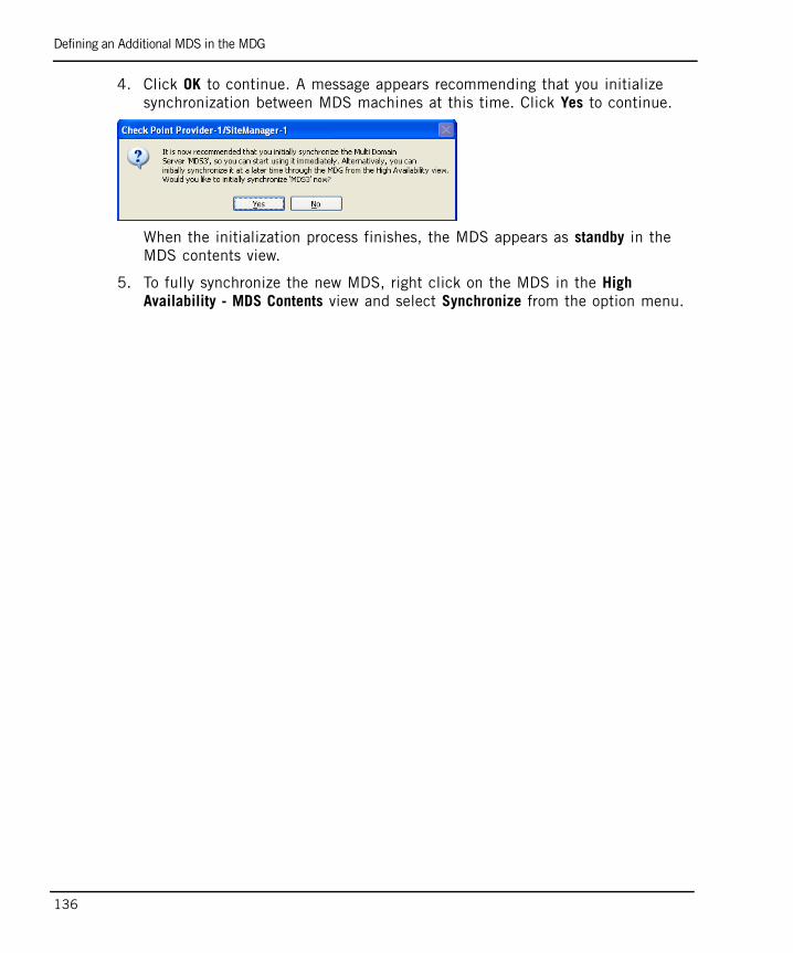
Defining an Additional MDS in the MDG
136
4. Click OK to continue. A message appears recommending that you initialize synchronization between MDS machines at this time. Click Yes to continue.
When the initialization process finishes, the MDS appears as standby in the MDS contents view.
5. To fully synchronize the new MDS, right click on the MDS in the High Availability - MDS Contents view and select Synchronize from the option menu.

Defining Provider-1 Customers and CMAs
Chapter 4 Using VSX With Provider-1 137
Defining Provider-1 Customers and CMAsThis section describes define and manage customers using the Provider-1 MDG. A Customer is a Provider-1 object that represents a discrete business entity whose networks are protected by Check Point security solutions, including VSX. In many Provider-1 deployments, customer objects represent the physical customers of a managed service provider or data center.
The Customer Management Add-on (CMA) is a Provider-1 object that manages a protected network for a specific customer, emulating the functionality of SmartCenter server. The CMA manages all Virtual Systems and other virtual devices, as well as any physical VPN-1 gateways and other Check Point devices protecting the customer network. An individual customer can have multiple CMAs, but they must reside on separate MDSs.
Once you have defined CMAs for a customer, you can begin defining Virtual Systems, other virtual devices and physical devices for your customer. Section “Working with Virtual Devices” on page 145, describes how to define virtual devices for a CMA.
Creating a New Customer Object To create a new Provider-1 customer, perform the following procedures:
Starting the Add Customer Wizard1. In the Customer Contents area of the MDG, right-click on Provider-1 and select
New Customer. The Add Customer wizard opens, displaying the General Definitions page.
2. Enter an object name for the customer in the Customer Name field. Only alphanumeric characters and the underscore character are valid.

Creating a New Customer Object
138
3. If you are defining a CMA that will only manage Virtual Systems, clear the Enable QoS option, as this option is not relevant for VSX environments.
Customer Properties PageEnter the customer or business entity name, contact person name and contact person email in the appropriate fields on the Customer Properties page:

Creating a New Customer Object
Chapter 4 Using VSX With Provider-1 139
Global Policy PageThe Global Policy page defines how global policies are applied to a CMA. Global Policies are collections of rules and global objects that apply by default to the entire Provider-1 environment or to defined groups of customers.
Global Objects
When assigning a global policy to a CMA, you can choose to assign all global objects or to assign only those objects required by the global policy Rule Base. Select the appropriate option for this new customer.
SmartDefense
Enable the Subscribe Customer to SmartDefense Service option to assign the global SmartDefense policy to this customer along with the global policy. Choose one of the following global SmartDefense policy options:
• Override: Replace all SmartDefense configuration settings with the global settings (default)
• Merge: Preserve any manual SmartDefense configuration settings for this customer, but update all other settings using the latest Global settings

Creating a New Customer Object
140
Revision Control
Enable the Create database version option to save a snapshot of current settings whenever a new policy is installed. This allows administrators to roll back to previous configurations.
Customer Assigned Administrators PageThis page allows you to assign and define specific administrators that are authorized to manage this customer and his protected networks. This are in addition to the Provider-1 superusers who are assigned automatically.
To assign an administrator to this customer, select one or more administrators or administrator groups from the Not Assigned column and click Add. The administrator moves to the Assigned column and the Edit Administrator’s Customer-Level Permissions window opens. Assign administrator permissions as described in “Assigning Permissions to Administrators” on page 141.
To remove an administrator, select one or more administrators or administrator groups from the Assigned column and click Remove. The administrator moves to the Not Assigned column.
To create a new administrator, click New Admin and configure the appropriate properties. For more information on assigning/unassigning or adding new administrators, refer to the Provider-1/SiteManager-1 Administration Guide.

Creating a New Customer Object
Chapter 4 Using VSX With Provider-1 141
Assigning Permissions to Administrators
You can define custom permissions for individual administrators and administrator groups that allow or deny access to specific administrative tasks. Of particular interest to VSX users, is the option to restrict an administrator’s permission to provision VSX objects.
To assign permissions, select an administrator in the Not Assigned column and click Add or select an administrator in the Assigned window and click Permissions. The Edit Administrator’s Customer-Level Permissions window opens.
Select the Customized option to customize administrator permissions, and enable or disable individual task permissions as appropriate. Refer to the online help for details regarding individual options and task permissions.
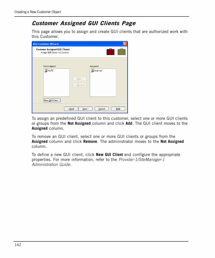
Creating a New Customer Object
142
Customer Assigned GUI Clients PageThis page allows you to assign and create GUI clients that are authorized work with this Customer.
To assign an predefined GUI client to this customer, select one or more GUI clients or groups from the Not Assigned column and click Add. The GUI client moves to the Assigned column.
To remove an GUI client, select one or more GUI clients or groups from the Assigned column and click Remove. The administrator moves to the Not Assigned column.
To define a new GUI client, click New GUI Client and configure the appropriate properties. For more information, refer to the Provider-1/SiteManager-1 Administration Guide.

Creating a New Customer Object
Chapter 4 Using VSX With Provider-1 143
Management Plug-ins PageThis page allows you to activate plug-in features for this customer. You must activate the VSX plugin (Plvsx) for all customers managing VSX NGX R65 virtual systems.To
To activate the VSX plugin, select Plvsx from the Not Activated column and click Add. The plug-in moves to the Activated column. You can also use the vsx_util activate_plugin command to automatically activate the VSX plug-in for all customers managing virtual devices on a specific VSX gateway or cluster. Refer to “activate_plugin” on page 290 for further details.
Adding a CMAThe Customer Management Add-ons page allows you to define a CMA to manage this customer’s network. Select Yes to continue with the CMA definition or No to define the CMA later. If you select Yes, you can define up to two CMAs for this customer at this point. You can add additional CMAs later.
To add a CMA after you complete a customer definition, simply right click on the customer in the Customer Contents view and select Add Customer Management Add-on from the option menu.
Note - You can only add one CMA for per customer on each MDS defined in your system. For example, you can must have at least three MDSs if you wish to define three CMAs for a customer. Additional CMAs can be used as high availability standbys or to spread management traffic over several MDS machines.
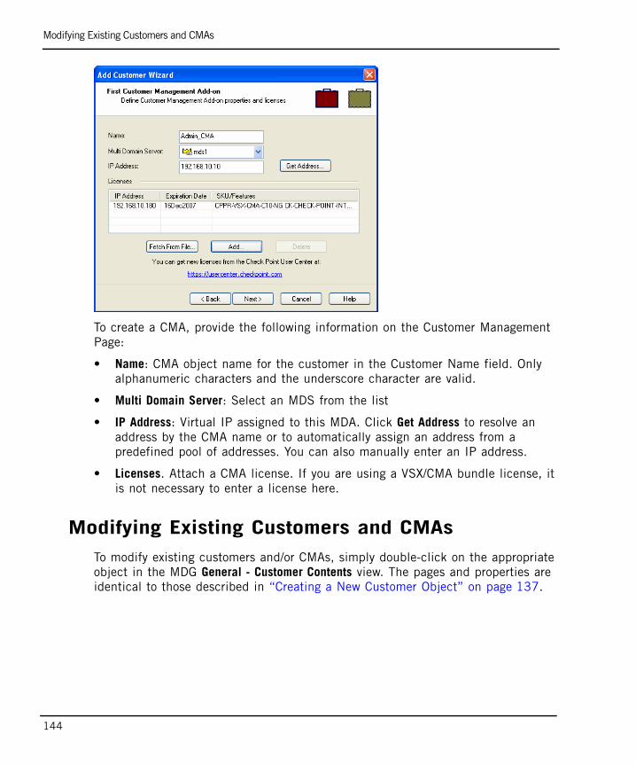
Modifying Existing Customers and CMAs
144
To create a CMA, provide the following information on the Customer Management Page:
• Name: CMA object name for the customer in the Customer Name field. Only alphanumeric characters and the underscore character are valid.
• Multi Domain Server: Select an MDS from the list
• IP Address: Virtual IP assigned to this MDA. Click Get Address to resolve an address by the CMA name or to automatically assign an address from a predefined pool of addresses. You can also manually enter an IP address.
• Licenses. Attach a CMA license. If you are using a VSX/CMA bundle license, it is not necessary to enter a license here.
Modifying Existing Customers and CMAsTo modify existing customers and/or CMAs, simply double-click on the appropriate object in the MDG General - Customer Contents view. The pages and properties are identical to those described in “Creating a New Customer Object” on page 137.

Working with Virtual Devices
Chapter 4 Using VSX With Provider-1 145
Working with Virtual DevicesWhen defining and managing virtual devices in Provider-1, you must use the SmartDashboard associated with a specific CMA. Otherwise, the configuration procedures are identical to those for a SmartCenter server management model. Provider-1 treats virtual devices much in the same manner as physical devices.
You can add as many Virtual Systems to CMAs as your license permits. Virtual Systems added to a CMA do not have to reside on the same VSX gateway or cluster. For more information regarding CMAs, refer to the Provider-1/SiteManager-1 Administration Guide.
Adding Virtual System to a CMATo add a new Virtual System to a CMA, perform the following steps:
1. In the MDG, launch SmartDashboard from the appropriate CMA.
2. Create and configure the Virtual System as described in “Creating a New Virtual System” on page 75.
3. Define and install a security policy.
Adding Virtual Routers and Switches to a CMATo add Virtual Routers and Switches to a CMA, perform the following steps:
1. In the MDG, launch SmartDashboard from the appropriate CMA.
2. Create and configure the Virtual System as described in “Creating a New Virtual Router” on page 92 or “Adding Virtual Switches” on page 103.

Working with Virtual Devices
146

147
Chapter 5Introduction to VSX Clusters
This chapter presents a conceptual overview of VSX cluster deployments, with
emphasis on clustering features and their application. This discussion assumes that the reader is familiar with network cluster applications and environments, particularly Check Point ClusterXL.
For details regarding cluster management and configuration, including instructions for enabling and using VSX clustering features, please refer to Chapter 6, “Managing VSX Clusters”. For additional information regarding Check Point clustering concepts and their application, please refer to the ClusterXL Administration Guide.
VSX Clustering Overview page 148
VSX High Availability page 154
Virtual System Load Sharing (VSLS) page 156
Bridge Mode page 164
VSX Clustering Overview
148
VSX Clustering OverviewIn This Section
VSX clusters provide redundancy and load sharing features for Virtual Systems and other virtual devices. A VSX cluster consists of two or more, interconnected VSX gateways that ensure continuous data synchronization. Cluster member do not need to be 100% identical, however they all must have the minimum number of interfaces necessary to support the deployment, and those interfaces must have the same names on each member (e.g. eth0, eth1).
VSX high availability ensures continuous data flow by ensuring transparent gateway failover of VSX gateways and Virtual System. Virtual System Load Sharing (VSLS) enhances system performance by distributing active Virtual Systems amongst cluster members.
The advantages of using clusters in a VSX environment include:
• Transparent failover in case of gateway or Virtual System failure
• State synchronization ensures zero downtime for mission-critical environments
• Load sharing ensures optimal system throughput during peak traffic periods
• Provides for superior scalability, because it allows you to greatly increase system capacity with minimal hardware investment.
Physical ClustersVSX clustering is based on VPN-1 clustering concepts. This section reviews those VPN-1 clustering concepts, and then demonstrates how these principles apply to VSX virtualization.
In a typical VPN-1 deployment, clusters consist of two or more interconnected physical VPN-1 gateways to provide redundancy and/or load sharing. This cluster behaves as a single gateway and is assigned its own IP address, which is known as its cluster IP or virtual IP. This cluster IP address is distinct from the physical IP addresses of its members, which are hidden from the protected networks.
Physical Clusters page 148
VSX Clusters page 150
Supported Cluster Environments page 151

Physical Clusters
Chapter 5 Introduction to VSX Clusters 149
Traffic from external networks or the Internet directed to internal networks arrives to the external cluster IP address. Depending on the clustering model (high availability or load sharing), a designated cluster member receives the traffic and performs the required inspection. Following inspection, traffic is either sent to its destination on the internal network, or is dropped.
Internal networks send traffic destined for the Internet or external networks via the cluster IP address as a next hop gateway. The traffic is then processed by the designated cluster member, inspected, and, if allowed, forwarded to its external destination.
Each member interface has a unique, physical IP addresses. These IP addresses, which are invisible to physical networks, are assigned to virtual device and VSX gateway interfaces. They are used for internal communication between members and the VSX gateway. Management interfaces handle communication between members and the management server for such tasks as downloading policies, sending logs and checking the status of individual cluster members.

VSX Clusters
150
VSX ClustersVSX clusters, like their physical counterparts, connect two or more synchronized gateway members in such a way that if one fails, another immediately takes its place. VSX clusters are defined at two levels:
VSX ensures that virtual devices and their interfaces are provisioned and configured identically on each cluster member. Figure 5-1 shows that each cluster member contains identical instances of each virtual device. These identical instances are referred to as peers.Figure 5-1 Typical VSX cluster deployment
VSX performs the following cluster management functions:
• Assigning virtual IP addresses: Each virtual device interface requires its own IP address.
• State synchronization: Virtual device state tables are synchronized to peers on other cluster members.
Supported Cluster Environments
Chapter 5 Introduction to VSX Clusters 151
Supported Cluster EnvironmentsVPN-1 Power VSX NGX R65 supports the following proprietary clustering environments.
• Check Point ClusterXL High Availability
• Check Point ClusterXL Virtual System Load Sharing
• Crossbeam Systems XOS
• Nokia VRRP
The procedures presented in this Administration Guide focus on Check Point Cluster XL environments. If you are using one of the other supported environments, please refer to their documentation for assistance in implementing VSX cluster deployments.

Planning a Cluster Deployment
152
Planning a Cluster DeploymentAs with physical network deployments, advance planning is the key to successfully implementing a virtual network. This section discusses basic of IP address allocation in a VSX environment. Your VSX configuration choices affect the number of IP addresses required, both public and private.
VSX Cluster ArchitectureIP address allocation in a VSX cluster network is similar to IP address allocation for physical networks. During the provisioning process, administrators assign private IP addresses to cluster member internal and external interfaces, the management interface and the state synchronization network interface, as well as a public, virtual IP address to the cluster object itself. Virtual IP addresses should also be assigned to VLAN interfaces.
VSX simplifies the IP address management task by automatically assigning virtual IP addresses to Warp Links between virtual devices. For example, Warp Links between a Virtual Router and its associated Virtual Systems are created automatically and assigned IP addresses without user intervention.
A VSX cluster contains the following components:
• Synchronization Network
• Internal Communications Network
• Cluster IP address
Synchronization NetworkThe synchronization network is a physical network that carries state synchronization data between cluster members. You define the synchronization network and assign its IP addresses during the initial VSX cluster definition process (VSX Cluster Wizard) and you can modify the definition as necessary afterwards.
State synchronization can be used for Check Point ClusterXL deployments as well as for other OPSEC-certified VSX solutions. The synchronization network must be configured using unique IP addresses that are not used anywhere else in the enterprise network.
Planning a Cluster Deployment
Chapter 5 Introduction to VSX Clusters 153
Internal Communication NetworkThe internal communication network is a “virtual” network that enables cluster members to communicate with each other in Check Point ClusterXL environments. it is separate from the synchronization network and is invisible to external networks.
VSX automatically an IP addresses to the internal communication network during the cluster definition process. The default IP address range is as follows:
IP address: 192.168.196.0/22
The IP addresses used assigned to the internal communication network must be unique and not used in any internal networks. You can modify the default IP address range, but only before creating Virtual Systems. Once Virtual Systems have been created, you cannot change IP address range.
Cluster AddressesThe cluster IP address is public, and visible to internal and external networks. It must be a member of a directly-connected subnet and routable as a valid next hop address. These IP addresses are similar to virtual addresses configured across traditional cluster setups.

VSX High Availability
154
VSX High Availability This section describes VSX high availability features. In a VSX environment, you can work with one of two high availability scenarios:
VSX Gateway High Availability: VSX gateway high availability ensures continuity of service by initiating failover of all virtual devices on the primary member to a designated standby member. Failover occurs if the member itself fails or any one of its virtual devices fails.
Per Virtual System High Availability: In the event that a problem is detected with an individual Virtual System, that Virtual System fails over to another member while all other Virtual Systems continue to function on the original member.
In either scenario, all members and virtual systems function in an active/standby mode and are continuously synchronized.
VSX Gateway High AvailabilityEach cluster member functions as a VSX gateway and is synchronized with the other members. If one member goes down, it immediately fails over to another member. Likewise, if a problem is detected with an individual virtual device, the entire member fails over to another member.
VSX gateway high availability is the default cluster configuration. If neither Per Virtual System nor Virtual System Load Sharing (VSLS) is active, a cluster functions in the VSX Gateway high availability mode. All members of a cluster must be configured to use the same clustering mode.Figure 5-2 VSX Gateway high availability
In the above example, member M1 experiences a failure that affects VS1, causing all Virtual Systems to immediately fail over to member M2.

Per Virtual System High Availability
Chapter 5 Introduction to VSX Clusters 155
Per Virtual System High AvailabilityWith per Virtual System high availability, each Virtual System monitors its own interfaces for failure, as illustrated in Figure 5-3:Figure 5-3 Per Virtual System high availability
In this example, each cluster member contains three identical, synchronized Virtual Systems. The member designated as M1 currently process traffic for all Virtual Systems. If VS2 fails on M1, it fails over to its peer in M2. VS1 and VS3 continue to function normally on M1.
When using Virtual System high availability, you must enable the Per Virtual System State option. You must connect each Virtual System directly to a physical interface, or to a VLAN. You cannot connect to a Virtual Router or Virtual Switch.

Virtual System Load Sharing (VSLS)
156
Virtual System Load Sharing (VSLS)VSX clusters can efficiently balance network traffic load by distributing active virtual systems amongst cluster members. This capability is known as Virtual System Load Sharing (VSLS), which provides the following benefits:
• Capacity: VSLS leverages the cluster machines to handle greater network volume by efficiently distributing the load.
• Redundancy: VSLS provides redundancy by maintaining connectivity for all Virtual Systems even when individual members fail.
• Scalability: VSLS provides scalability for throughput and session rate.
• Cost Effectiveness: A VSLS cluster uses standard network switches to achieve cost effective load sharing.
• Ease of Configuration: Virtual Systems are automatically distributed among all the cluster members - no special configuration is required.
• Priority Designation: Mission-critical Virtual Systems can be separated from the other Virtual Systems, providing advantages in terms of bandwidth and resources.
• System Scalability: Every cluster member added to the cluster increases the overall system capacity and redundancy.
Requirements• VSLS is supported only when using Check Point ClusterXL.
• You must enable the Per Virtual System State option.
• Since VSLS requires the Per Virtual System State option, you must connect each Virtual System directly to a physical interface, or to a VLAN. You cannot connect to a Virtual Router.
Conceptual Overview
Chapter 5 Introduction to VSX Clusters 157
Conceptual OverviewThis section presents a detailed conceptual overview of ClusterXL Virtual System Load Sharing.
In This Section
IntroductionVirtual System Load Sharing (VSLS) for VSX differs from ClusterXL load sharing for VPN-1 gateways, in that it is not connection-based. It works by distributing active Virtual Systems amongst different cluster members, thereby balancing the traffic load. Likewise, standby and backup Virtual Systems are distributed amongst different members.
VSLS allows administrators to manually assign specific Virtual Systems to specific cluster members, or to allow the system to determine the dispersal configuration automatically. See “Configuring Virtual System Load Sharing (VSLS)” on page 205 for configuration information.
Introduction page 157
Virtual System Priority page 158
Virtual System Weight page 158
Virtual System States page 159
Normalized VSLS Deployment Scenario page 160
Member Failure Scenario page 161
Virtual System Failure Scenario page 162
Failure Recovery page 162
Note - A VSX cluster cannot use VSLS if it contains Virtual Routers.

Conceptual Overview
158
Virtual System PriorityVirtual System priority refers to a preference regarding which member hosts a Virtual System’s active, standby, and backup states. This preference is expressed as an integer value, as shown in the following table.
You can change the priority designation using the vsx_util redistribute_vsls command. See “Distributing Virtual Systems Amongst Members” on page 206.
Virtual System WeightSince all Virtual Systems are not equal in terms of traffic and load, VSLS allows you to assign “weights” to individual Virtual Systems. The weight of a Virtual System affects the dispersal pattern of other Virtual Systems across cluster members. Assigning a heavier weight to a Virtual System gives it a larger share of a particular member’s resources, and accordingly, disperses the other Virtual Systems to other cluster members.
By default, all virtual systems are assigned an equal weight factor of 10. You can change the weight factor using the vsx_util redistribute_vsls command. See “Distributing Virtual Systems Amongst Members” on page 206.
Priority Definition
0 Highest priority, indicating the cluster designated to host the Virtual System’s active state.
1 Second highest priority, indicating the member designated to host the Virtual System’s standby state.
> 1 Lower priorities, indicating the members designated to host a Virtual System’s backup state. The cluster member assigned priority 2 will be the first to switch the Virtual System to the Standby state in the event of a failure of either the Active or Standby Virtual System. A cluster member assigned priority 3 would be the next in line to come online in the event of another failure.

Conceptual Overview
Chapter 5 Introduction to VSX Clusters 159
Virtual System StatesVSLS introduces a backup state in addition to the existing active and standby states. Virtual Systems in the backup state contain the latest configuration settings, but do not receive state table synchronization. VSLS facilitates unicast synchronization between Virtual Systems, which reduces the load on the synchronization network. The relationship between Virtual System states is illustrated in Figure 5-4.Figure 5-4 Load sharing Virtual System states
Each Virtual System peer in a VSLS cluster is replicated on all cluster members, and each copy exists in a different state. The active and standby state are synchronized so that the standby peer can immediately become active in the event of a failure of the active Virtual System or member. When this happens, one of the backup peers becomes the standby, and immediately synchronizes with the new active Virtual System.
VSLS reduces the load on the synchronization network by not synchronizing the backup Virtual System state tables with the active Virtual System until a failover occurs.
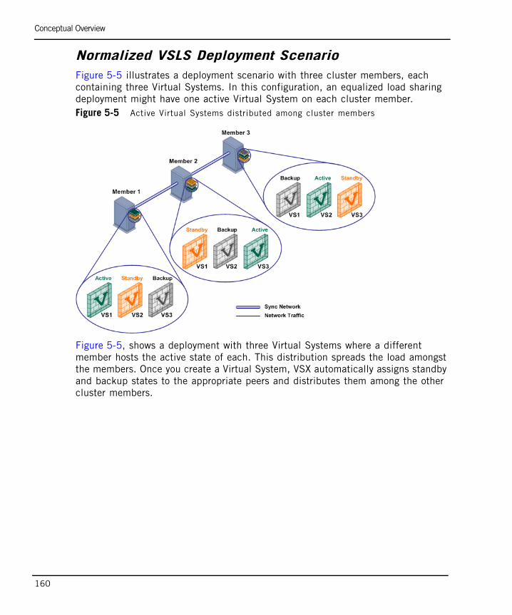
Conceptual Overview
160
Normalized VSLS Deployment ScenarioFigure 5-5 illustrates a deployment scenario with three cluster members, each containing three Virtual Systems. In this configuration, an equalized load sharing deployment might have one active Virtual System on each cluster member. Figure 5-5 Active Virtual Systems distributed among cluster members
Figure 5-5, shows a deployment with three Virtual Systems where a different member hosts the active state of each. This distribution spreads the load amongst the members. Once you create a Virtual System, VSX automatically assigns standby and backup states to the appropriate peers and distributes them among the other cluster members.

Conceptual Overview
Chapter 5 Introduction to VSX Clusters 161
Member Failure ScenarioIn the event that a member fails or experiences a connectivity problem, VSLS detects the problem and directs traffic destined to the affected Virtual Systems to their respective standby peers. Standby Virtual Systems, which are fully synchronized with their active peers, switch immediately to the active state and preserve active connections. At the same time, the backup Virtual System switches to standby, and fully synchronizes with the newly active Virtual Systems.
In a deployment where there is more than one backup peer for a given Virtual System, only one of the backup peers switches to standby, while any others remain as backup peers.
To see the effect of this failover, compare Figure 5-5 with Figure 5-6 below.Figure 5-6 Cluster member failure scenario
In this scenario, Member 1 fails and its active and standby Virtual Systems fail over to Members 2 and 3. The active Virtual System (VS1) moves to Member 2 and directs all VS 1 traffic itself. Its backup peer on Member 3 synchronizes with the new active Virtual System and becomes the standby.
VS2 on Member 2 becomes the standby and synchronizes with the active peer on Member 3. For VS3, the active and standby peers remain the same.
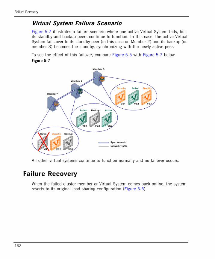
Failure Recovery
162
Virtual System Failure ScenarioFigure 5-7 illustrates a failure scenario where one active Virtual System fails, but its standby and backup peers continue to function. In this case, the active Virtual System fails over to its standby peer (in this case on Member 2) and its backup (on member 3) becomes the standby, synchronizing with the newly active peer.
To see the effect of this failover, compare Figure 5-5 with Figure 5-7 below.Figure 5-7
All other virtual systems continue to function normally and no failover occurs.
Failure RecoveryWhen the failed cluster member or Virtual System comes back online, the system reverts to its original load sharing configuration (Figure 5-5).
Distributing Virtual Systems Amongst Members
Chapter 5 Introduction to VSX Clusters 163
Distributing Virtual Systems Amongst MembersThe primary advantage of VSLS is the ability to distribute active, standby and backup Virtual Systems amongst cluster members in order to maximize throughput and user response time. You can choose to distribute Virtual Systems in one of the following manners:
• Automatically distribute active Virtual Systems amongst cluster members so that each member is equally loaded
• Automatically place all active Virtual Systems on the same member
• Manually configure priorities and weights for each Virtual System.

Bridge Mode
164
Bridge ModeIn This Section
By implementing native layer-2 bridging instead of IP routing, you can add Virtual Systems without adversely affecting the existing topology.
VSX NGX R65 supports the following Bridge mode models:
• STP Bridge Mode: Provides redundancy while preventing undesirable loops between redundant switches.
• Active/Standby Bridge Mode: Provides path redundancy and loop prevention, while offering seamless support for Virtual System Load Sharing and overcoming many STP Bridge mode limitations.
Failover in the Bridge ModeThis section describes how failover occurs in clusters with Virtual Systems in the Bridge Mode. Switches forward traffic according to MAC addresses stored in the switch forwarding table. When an active member or Virtual System fails, the switch forwarding table must be updated in order to forward traffic to the correct member.
ClusterXL accomplishes this by “teaching” the switch about the new cluster member. The newly active member achieves this by sending dummy packets with source MAC addresses of hosts located behind the firewall to the switch. This updates the switch forwarding table with the new member MAC address because the hosts are now protected by a Virtual System on that member.
Failover in the Bridge Mode page 164
Spanning Tree Protocol (STP) Bridge Mode page 165
Active/Standby Bridge Mode page 167
Spanning Tree Protocol (STP) Bridge Mode
Chapter 5 Introduction to VSX Clusters 165
Spanning Tree Protocol (STP) Bridge Mode
The Spanning Tree Protocol is an industry standard technology designed to prevent loops in high-speed switched networks. The STP Bridge mode is a good choice for internal network deployments.
To use the STP Bridge mode, you must have STP deployed and properly configured on your network. VSX NGX R65 supports the following STP layer-2 protocols:
• 802.1q
• 802.1D
• 802.1s
• 802.1w
• PVST+
Deploying and configuring STP on your network hardware is beyond the scope of this document. Please refer to your hardware documentation for assistance.
Limitations of the STP Bridge ModeThe STP Bridge mode presents several limitations that inhibit its usability in some applications.
• Slow failover (1 minute in standard STP and 5 seconds in RSTP)
• Does not support VSLS
• Distribution of activity/standby Virtual System peers amongst members is determined by the STP process and cannot be altered using VSX. Both the active and standby members may handle some packets.
• Does not support the following scenarios
- Active Streaming
- VPN
- Authentication
- Security servers
- NAT

Spanning Tree Protocol (STP) Bridge Mode
166
PVST+ Load SharingPer VLAN Spanning Tree Plus (PVST+) provides PVST functionality using standard 802.1Q VLAN trunking technology instead of ISL. You can use PVST+ with VSX NGX R65 to create a limited, per-Virtual System load sharing solution that maintains compatibility with the STP protocol.
PVST+ implements load sharing by creating a separate spanning tree for each VLAN. You can configure PVST+ in such a way that a the spanning tree for given VLAN connected to a Virtual System assigns a higher priority to one member than its peer in another member, thereby distributing the load amongst members.
For example, in Figure 5-8, PVST+ is configured so that VLANs 02 and 04 in member M1 receive higher priority than their peers member M2. VLAN 03 in member 2 receives the higher priority.Figure 5-8 Load sharing between Virtual Systems
-
Note - Virtual Systems in the Bridge mode must be connected directly to a physical or VLAN interface to accept decisions made by the STP algorithm.
Active/Standby Bridge Mode
Chapter 5 Introduction to VSX Clusters 167
Active/Standby Bridge ModeThe Active/Standby Bridge Mode provides path redundancy and loop prevention, while offering seamless support for Virtual System Load Sharing and overcoming many STP Bridge mode limitations. It also provides wider functionality and improved performance for VSX cluster environments.
When working in the Active/Standby Bridge mode, Virtual System interfaces do not require IP addresses. You may optionally assign an IP address to the Virtual System itself (not the interfaces) to enable layer-3 monitoring. This feature enhances network fault detection, but has no impact on network connectivity.
Active/Standby Bridge mode offers the following advantages:
- Instantaneous failover
- Enhanced administrator control over bridge failover.
- Works with VSLS
- Supports a mixed mode environment with bridges connect to routers.
- Supports bridge interface monitoring
The principal limitation of the Active/Standby bridge mode is that it breaks the STP tree structure.
Deployment ScenariosThis section presents illustrative Active/Standby Bridge mode deployments, which cannot function using a standard STP Bridge mode configuration.
Note - When configuring a VSX Cluster in the Active/Standby Bridge Mode, disable the spanning tree for all VLANS defined in switches. This action prevents delays due to trunk interface failback. This note also applies to non-bridge mode deployments.

Active/Standby Bridge Mode
168
VLAN Shared Interface Deployment with VSLS
In this deployment, each individual member connects to pair of redundant switches via a VLAN trunk. All Virtual Systems in a given member share the same VLAN trunk. The following figure illustrates example of such a deployment with active, standby and backup members.Figure 5-9 VLAN Shared Interface Deployment with VSLS
In VSLS deployments, the system distributes the traffic load amongst members according to predefined preferences. See “Virtual System Load Sharing (VSLS)” on page 156 for further details.
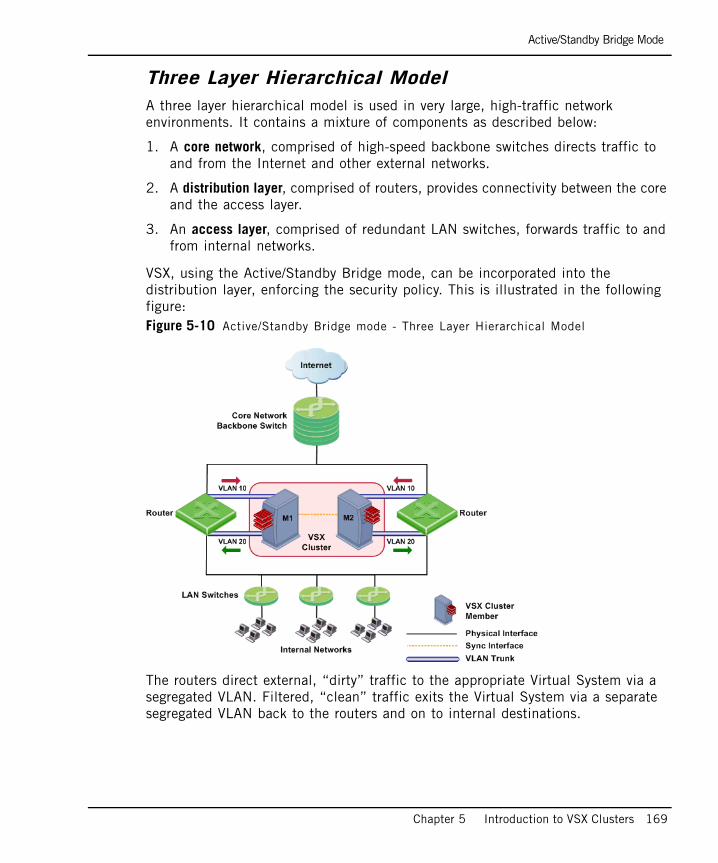
Active/Standby Bridge Mode
Chapter 5 Introduction to VSX Clusters 169
Three Layer Hierarchical Model A three layer hierarchical model is used in very large, high-traffic network environments. It contains a mixture of components as described below:
1. A core network, comprised of high-speed backbone switches directs traffic to and from the Internet and other external networks.
2. A distribution layer, comprised of routers, provides connectivity between the core and the access layer.
3. An access layer, comprised of redundant LAN switches, forwards traffic to and from internal networks.
VSX, using the Active/Standby Bridge mode, can be incorporated into the distribution layer, enforcing the security policy. This is illustrated in the following figure:Figure 5-10 Active/Standby Bridge mode - Three Layer Hierarchical Model
The routers direct external, “dirty” traffic to the appropriate Virtual System via a segregated VLAN. Filtered, “clean” traffic exits the Virtual System via a separate segregated VLAN back to the routers and on to internal destinations.

Using Virtual Switches in a Cluster
170
Using Virtual Switches in a ClusterIn a VSX cluster, Virtual Switches are also clustered for redundancy. Virtual Switches in the cluster are defined as active/active.
You can monitor the physical interface connected to the Virtual Switch by means of the ClusterXL Control Protocol (CCP). In the event of a failover, the standby Virtual System becomes active, and sends gratuitous ARPs from the Warp link between the Virtual System and the Virtual Switch.Figure 5-11 Clustered Virtual Switches
Figure 5-11 shows a simplified VSX high availability cluster deployment (per virtual system state disabled) with two members, one active, the other standby. The Virtual Switches within each cluster are active/active. When the physical interface connected to either Virtual Switch fails to respond, a failover occurs.

171
Chapter 6Managing VSX Clusters
In This Chapter
This chapter presents the procedures for configuring VPN-1 Power VSX NGX R65 in various cluster deployment scenarios. In addition to the basic scenarios, conceptual material and illustrative examples are presented for several advanced features, including the Bridge mode and dynamic routing.
Configuration Overview page 172
Creating a New Cluster page 172
Modifying a Cluster Definition page 181
Working with Cluster Members page 193
Changing the Cluster Type page 199
Configuring VSX High Availability page 201
Configuring Virtual System Load Sharing page 204
Configuring Virtual Systems in Bridge Mode page 209
Advanced Clustering Configuration page 215
Configuration Overview
172
Configuration OverviewThe majority of the basic cluster configuration process is performed using SmartDashboard, both in SmartCenter and Provider-1 management models. However, you will need to use the command line interface to add additional members, remove members and upgrade existing members to VSX clusters. Many advanced cluster management, including load sharing definitions, require the command line.
Creating a New ClusterThis section describes how to create a new VSX cluster using the VSX Cluster Wizard. The wizard guides you through the following steps to configure a VSX cluster.
After completing the VSX Cluster Wizard, you can modify most cluster and member properties directly from SmartDashboard.
To create a new cluster, perform the following steps:
1. Open SmartDashboard. If you are using Provider-1, open SmartDashboard from the CMA in which you are creating the cluster.
2. In the Network Objects tab in the Objects Tree, right-click Check Point and select New Check Point > VPN-1 Power VSX >Cluster . The VSX Cluster Wizard opens displaying the General Properties page.
Defining Cluster General Properties page 173
Selecting Creation Templates page 174
Adding Members page 175
Defining Physical Interfaces page 177
Cluster Management page 178
Virtual Network Device Configuration page 179
Completing the Wizard page 180

Defining Cluster General Properties
Chapter 6 Managing VSX Clusters 173
Defining Cluster General PropertiesThe Cluster General Properties page contains basic identification properties for VSX gateways.
This window contains the following properties:
• VSX Cluster Name: Unique, alphanumeric for the cluster. The name cannot contain spaces or special characters except the underscore.
• VSX Cluster IP Address: Management interface IP address.
• VSX Cluster Version: Select the VSX version to use for this cluster. In most cases this should be VPN-1 Power VSX NGX R65.
• VSX Cluster Platform: Select the platform type hosting the cluster members.
Note - All cluster members must use the type of platform, with the same specifications and configuration.

Selecting Creation Templates
174
Selecting Creation TemplatesThe Virtual Systems Creation Templates allows you to select a Virtual System Creation Template that applies predefined, default topology and routing definitions to Virtual Systems when they are first created. This feature ensures consistency among Virtual Systems and speeds up the provisioning process.
You always have the option of overriding the default creation template when creating or modifying a Virtual System
The available creation templates are as follows:
• Shared Interface: All virtual systems share a single external interface, but maintain separate internal interfaces.
• Separate Interfaces: All virtual systems use their own separate internal and external interfaces. This template creates a Dedicated Management Interface (DMI) by default.
• Custom Configuration: You manually create a custom configuration without any template.

Adding Members
Chapter 6 Managing VSX Clusters 175
Adding MembersThe VSX Cluster Members window defines the members of the new cluster. You must define at least two cluster here, and you can define as many as eight members. You can always add new member at a later time.
To add a new member, click Add. The Member properties window opens.
This window allows you to define the member name and IP address, as well as to initialize SIC trust between the member and the management server.
Enter the a unique member name and its IP address in the appropriate fields.

Adding Members
176
Establishing SIC TrustTo establish SIC trust, enter and confirm the activation key as defined when creating the cluster member, and then click Initialize. If you entered the correct activation key, the Trust State field changes to Trust established.
Troubleshooting SIC Trust Initialization Problems
If SIC trust was not successfully established, click Check SIC Status to display the reason for the failure. The most common issues are an incorrect activation key and connectivity problems between the management server and the cluster.
Try the following steps to resolve SIC initialization problems
• Re-enter and re-confirm the activation key.
• Verify that the IP address defined in General Properties is correct.
• Ping the management server to verify connectivity. Resolve any connectivity issues.
• From the cluster member command line, use the cpconfig utility to re-initialize SIC. After this process completes, click Reset in the wizard and then re-enter the activation key.
For more information regarding Secure Internal Communication, refer to the SmartCenter Administration Guide. Click Next to continue.
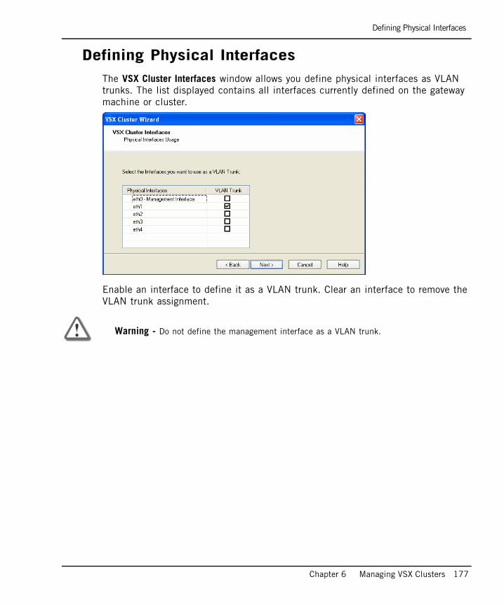
Defining Physical Interfaces
Chapter 6 Managing VSX Clusters 177
Defining Physical InterfacesThe VSX Cluster Interfaces window allows you define physical interfaces as VLAN trunks. The list displayed contains all interfaces currently defined on the gateway machine or cluster.
.
Enable an interface to define it as a VLAN trunk. Clear an interface to remove the VLAN trunk assignment.
Warning - Do not define the management interface as a VLAN trunk.

Cluster Management
178
Cluster ManagementThe VSX Gateway Management page allows you to define several security policy rules that protect the cluster itself. This policy is installed automatically on the new VSX gateway.
The security policy consists of predefined rules covering the following services:
• UDP: snmp requests
• TCP: ssh traffic
• ICMP: echo-request (ping)
• TCP: https traffic
Configuring the Cluster Security Policy
1. Allow: Enable a rule to allow traffic for those services for which you wish to allow traffic. Clear a rule to block traffic. By default, all services are blocked.
For example, you may wish to allow UDP echo-request traffic in order to be able to ping cluster members from the management server.
2. Source: Click the arrow and select a Source Object from the list. The default value is *Any. Click New Source Object to define a new source. Refer to the online help and the SmartCenter Administration Guide for further details.
Note - This policy applies only to traffic destined for the cluster. Traffic destined for Virtual Systems, other Virtual Devices, external networks, and internal networks is not affected by this policy.
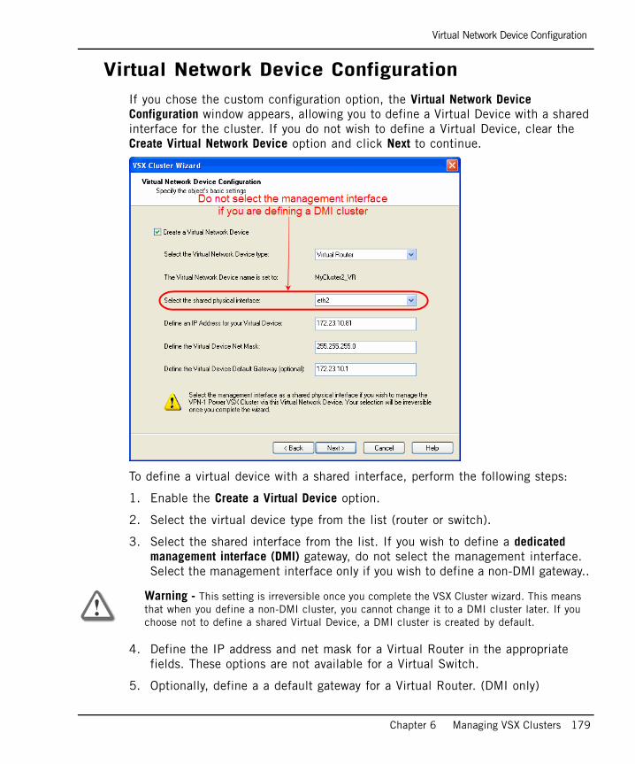
Virtual Network Device Configuration
Chapter 6 Managing VSX Clusters 179
Virtual Network Device ConfigurationIf you chose the custom configuration option, the Virtual Network Device Configuration window appears, allowing you to define a Virtual Device with a shared interface for the cluster. If you do not wish to define a Virtual Device, clear the Create Virtual Network Device option and click Next to continue.
To define a virtual device with a shared interface, perform the following steps:
1. Enable the Create a Virtual Device option.
2. Select the virtual device type from the list (router or switch).
3. Select the shared interface from the list. If you wish to define a dedicated management interface (DMI) gateway, do not select the management interface. Select the management interface only if you wish to define a non-DMI gateway..
4. Define the IP address and net mask for a Virtual Router in the appropriate fields. These options are not available for a Virtual Switch.
5. Optionally, define a a default gateway for a Virtual Router. (DMI only)
Warning - This setting is irreversible once you complete the VSX Cluster wizard. This means that when you define a non-DMI cluster, you cannot change it to a DMI cluster later. If you choose not to define a shared Virtual Device, a DMI cluster is created by default.

Completing the Wizard
180
Completing the WizardClick Next to continue and then click Finish to complete the VSX Cluster wizard. Please note that this may take several minutes to complete. A message appears indicating successful or unsuccessful completion of the process.
If the process ends unsuccessfully, click View Report to view the error messages. Refer to Chapter 9, “VSX Diagnostics and Troubleshooting”for further assistance.

Modifying a Cluster Definition
Chapter 6 Managing VSX Clusters 181
Modifying a Cluster DefinitionOnce you create a cluster using the wizard, you can modify the topology and other parameters using the VSX Cluster Properties window. This window also allows you to configure many advanced features not available with the wizard.
To work with a VSX cluster definition, double-click on the cluster object in the SmartDashboard Object Tree. The VSX Cluster Properties window opens, showing the General Properties page.
In This Section
Most cluster objects and properties can be defined using the SmartDashboard GUI. Several definitions, however, require CLI commands, while others may be performed using either method.
A brief explanation for each of the definition pages follows. More detailed explanations for features that are not specific to VSX (NAT, SmartDefense, VPN, etc.) are available in the online help or in the appropriate product Administration Guide.
General Properties page 182
Cluster Members page 183
ClusterXL page 185
Creation Templates page 185
Physical Interfaces page 186
Synchronization page 186
Topology page 187
NAT page 190
SmartDefense page 191
VPN page 191
Remote Access page 191
Authentication page 191
Logs and Masters page 191
Cooperative Enforcement page 192
Advanced Pages page 192
Changing the Cluster Management IP and/or Subnet page 192
Changing the Internal Communication Network IP page 192

Modifying Cluster Properties
182
Modifying Cluster PropertiesOnce you create a cluster using the Wizard, you can modify its topology and other parameters using the VSX Cluster Properties window. This window also allows you to configure advanced features that are not available with the wizard.
To work with a VSX cluster definition, double-click on the VSX gateway object in the SmartDashboard Object Tree. The VSX Cluster Properties window opens, showing the General Properties page.
General PropertiesUse the General Properties page to view general properties and to activate Check Point products for use with this cluster and its members.
You can modify the following properties:
• Comment: Free text comment that appears in the Object List and elsewhere
• Color: Color of the object icon as it appears in the Object Tree
• Check Point Products: Select Check Point products active on this gateway

Modifying Cluster Properties
Chapter 6 Managing VSX Clusters 183
Cluster MembersThe Cluster Members page enables you to modify several properties for individual cluster members, including IP addresses for members and the internal communication network. You can also view where cluster and member objects in the object database are used.
Gateway Cluster Member List
This tab shows the currently defined cluster members. Double-click on a member or select a member and click Edit to open its Cluster Member Properties window. You can modify the following member properties on various tabs as follows:
• General Tab:
- Comment: Free text comment that appears in the Object List and elsewhere
- Color: Color of the object icon as it appears in the Object Tree
- Secure Internal Communication: Check and reset SIC trust
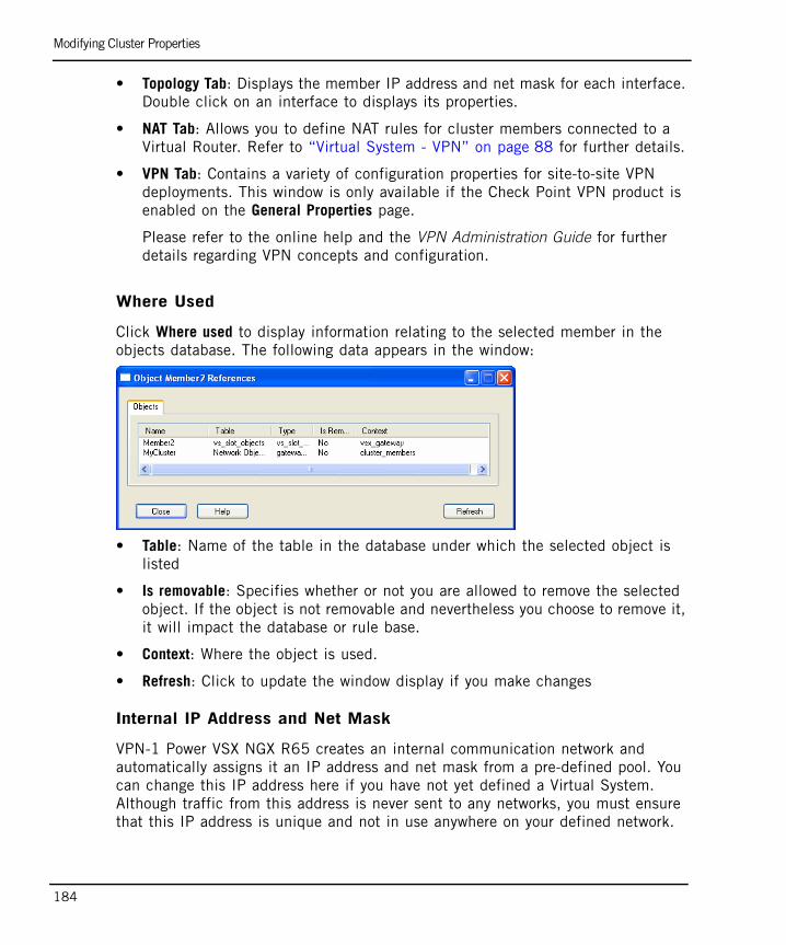
Modifying Cluster Properties
184
• Topology Tab: Displays the member IP address and net mask for each interface. Double click on an interface to displays its properties.
• NAT Tab: Allows you to define NAT rules for cluster members connected to a Virtual Router. Refer to “Virtual System - VPN” on page 88 for further details.
• VPN Tab: Contains a variety of configuration properties for site-to-site VPN deployments. This window is only available if the Check Point VPN product is enabled on the General Properties page.
Please refer to the online help and the VPN Administration Guide for further details regarding VPN concepts and configuration.
Where Used
Click Where used to display information relating to the selected member in the objects database. The following data appears in the window:
• Table: Name of the table in the database under which the selected object is listed
• Is removable: Specifies whether or not you are allowed to remove the selected object. If the object is not removable and nevertheless you choose to remove it, it will impact the database or rule base.
• Context: Where the object is used.
• Refresh: Click to update the window display if you make changes
Internal IP Address and Net Mask
VPN-1 Power VSX NGX R65 creates an internal communication network and automatically assigns it an IP address and net mask from a pre-defined pool. You can change this IP address here if you have not yet defined a Virtual System. Although traffic from this address is never sent to any networks, you must ensure that this IP address is unique and not in use anywhere on your defined network.
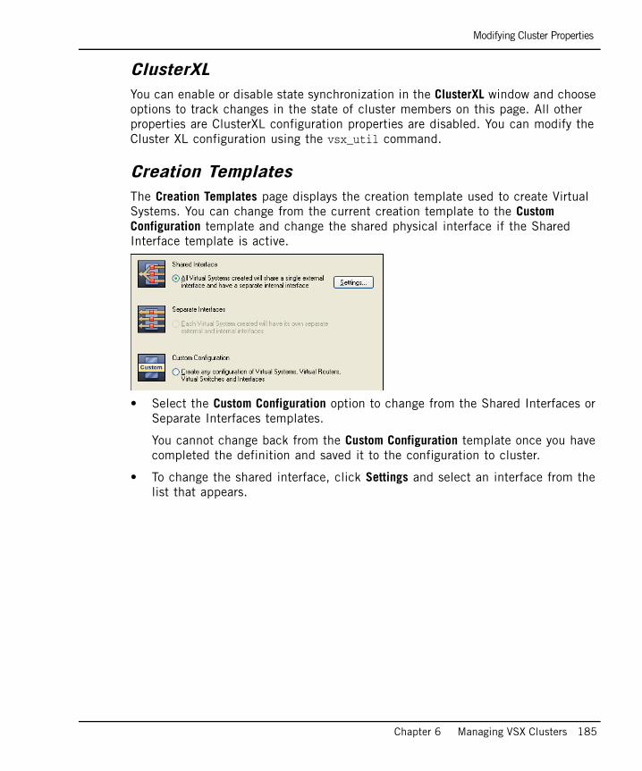
Modifying Cluster Properties
Chapter 6 Managing VSX Clusters 185
ClusterXLYou can enable or disable state synchronization in the ClusterXL window and choose options to track changes in the state of cluster members on this page. All other properties are ClusterXL configuration properties are disabled. You can modify the Cluster XL configuration using the vsx_util command.
Creation TemplatesThe Creation Templates page displays the creation template used to create Virtual Systems. You can change from the current creation template to the Custom Configuration template and change the shared physical interface if the Shared Interface template is active.
• Select the Custom Configuration option to change from the Shared Interfaces or Separate Interfaces templates.
You cannot change back from the Custom Configuration template once you have completed the definition and saved it to the configuration to cluster.
• To change the shared interface, click Settings and select an interface from the list that appears.

Modifying Cluster Properties
186
Physical InterfacesThe Physical Interfaces page allows you to add or delete a physical interface on the VSX gateway, and to define interfaces to be used as VLAN trunks.
• To add a new physical interface, click Add and enter the interface name in the appropriate field.
• To define an interface as a VLAN trunk, select the desired interface and enable the checkbox. To disable a VLAN trunk, clear the checkbox.
SynchronizationThe Synchronization window displays the state synchronization network. There are no editable properties.
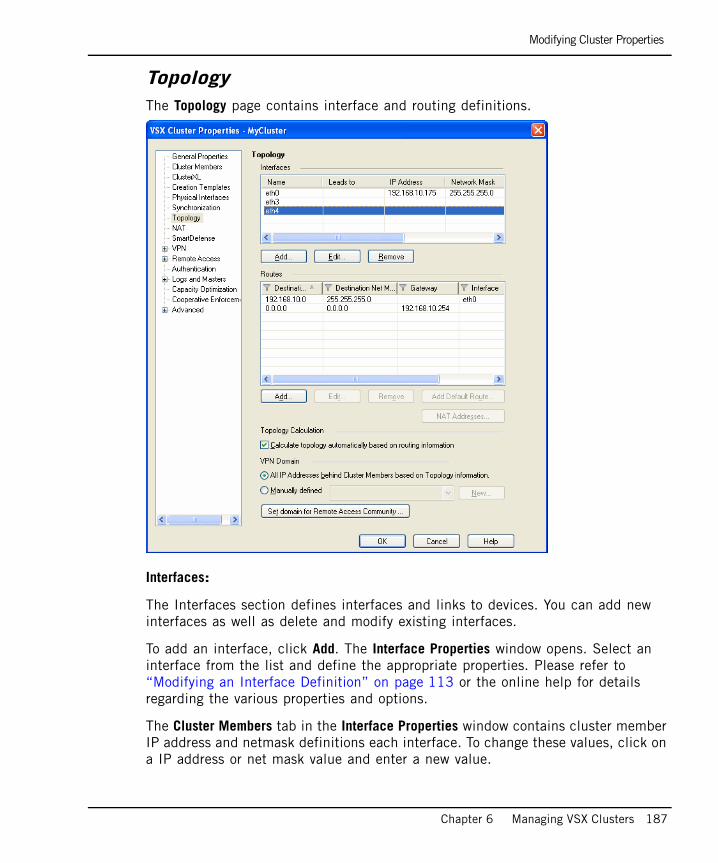
Modifying Cluster Properties
Chapter 6 Managing VSX Clusters 187
TopologyThe Topology page contains interface and routing definitions.
Interfaces:
The Interfaces section defines interfaces and links to devices. You can add new interfaces as well as delete and modify existing interfaces.
To add an interface, click Add. The Interface Properties window opens. Select an interface from the list and define the appropriate properties. Please refer to “Modifying an Interface Definition” on page 113 or the online help for details regarding the various properties and options.
The Cluster Members tab in the Interface Properties window contains cluster member IP address and netmask definitions each interface. To change these values, click on a IP address or net mask value and enter a new value.

Modifying Cluster Properties
188
Routes
The Routes section defines routes between Virtual Systems, external network devices, network addresses, and other virtual devices. Some routes are defined automatically based on the interface table. You can add new interfaces as well as delete and modify existing interfaces.
To add a default route to the routing table, click Add Default Routes and either enter the default route IP address or select the default router. The Route Configuration windows opens. Click Help for details regarding the various properties and options.
Calculating topology automatically based on routing information
Enable this option to allow VSX NGX R65 to automatically calculate the network topology based on interface and routing definitions (enabled by default). VSX NGX R65 creates a automatic links, or connectivity cloud objects linked to existing internal or external networks.
• This option is not available in the Bridge mode.
• When employing dynamic routing, it is recommended to disable this option.
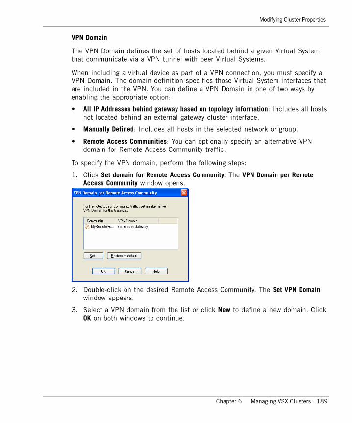
Modifying Cluster Properties
Chapter 6 Managing VSX Clusters 189
VPN Domain
The VPN Domain defines the set of hosts located behind a given Virtual System that communicate via a VPN tunnel with peer Virtual Systems.
When including a virtual device as part of a VPN connection, you must specify a VPN Domain. The domain definition specifies those Virtual System interfaces that are included in the VPN. You can define a VPN Domain in one of two ways by enabling the appropriate option:
• All IP Addresses behind gateway based on topology information: Includes all hosts not located behind an external gateway cluster interface.
• Manually Defined: Includes all hosts in the selected network or group.
• Remote Access Communities: You can optionally specify an alternative VPN domain for Remote Access Community traffic.
To specify the VPN domain, perform the following steps:
1. Click Set domain for Remote Access Community. The VPN Domain per Remote Access Community window opens.
2. Double-click on the desired Remote Access Community. The Set VPN Domain window appears.
3. Select a VPN domain from the list or click New to define a new domain. Click OK on both windows to continue.
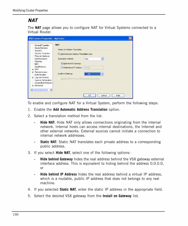
Modifying Cluster Properties
190
NATThe NAT page allows you to configure NAT for Virtual Systems connected to a Virtual Router.
To enable and configure NAT for a Virtual System, perform the following steps:
1. Enable the Add Automatic Address Translation option.
2. Select a translation method from the list.
- Hide NAT: Hide NAT only allows connections originating from the internal network. Internal hosts can access internal destinations, the Internet and other external networks. External sources cannot initiate a connection to internal network addresses.
- Static NAT: Static NAT translates each private address to a corresponding public address.
3. If you select Hide NAT, select one of the following options:
- Hide behind Gateway hides the real address behind the VSX gateway external interface address. This is equivalent to hiding behind the address 0.0.0.0, or
- Hide behind IP Address hides the real address behind a virtual IP address, which is a routable, public IP address that does not belongs to any real machine.
4. If you selected Static NAT, enter the static IP address in the appropriate field.
5. Select the desired VSX gateway from the Install on Gateway list.
Modifying Cluster Properties
Chapter 6 Managing VSX Clusters 191
SmartDefense Since VSX NGX R65 Virtual System on supports the default protection profile, this page has no configurable properties.
VPNThe VPN page contains a variety of configuration properties for clusters in site-to-site VPN deployments. This window is only available if the Check Point VPN product is enabled on the General Properties page.
Please refer to the online help and the VPN Administration Guide for further details regarding VPN concepts and configuration.
Remote AccessThe Remote Access page contains properties that govern establishing VPN connections with Remote Access clients. This window is only available if the Check Point VPN product is enabled on the General Properties page.
Please refer to the online help and the VPN Administration Guide for further details regarding VPN with Remote Access clients.
Authentication The Authentication page allows you to enable several different authentication options for a VSX gateway. Please refer to “Authentication” on page 114 for further details.
Logs and Masters The Logs and Masters page allows you define logging options for a VSX gateway. Please refer to “Tracking Activity with SmartView Monitor” on page 123 for further details.

Modifying Cluster Properties
192
Capacity OptimizationThe Capacity Optimization page allows you to maximize cluster and VPN throughput by limiting the number of concurrent connections, the number of concurrent IKE negotiations, and the number of concurrent VPN tunnels. To raise or lower the maximum, use the arrows in the appropriate field to set the desired value.
Cooperative EnforcementCooperative Enforcement works with Check Point Integrity servers. This feature utilizes the Integrity server compliance capability to verify connections arriving from various hosts across the internal network. The Cooperative Enforcement window contains several configuration properties for defining this feature. For more information, please refer to the online help and the Firewall & SmartDefense Administration Guide.
Advanced PagesThe VSX Bridge Configuration page allows you to specify the loop detection algorithm when working in the Bridge mode.
Enable the Check Point ClusterXL option to enable the Active/Standby Bridge mode loop detection algorithms contained in ClusterXL.
Enable the Standard Layer-2 Loop Detection Protocols to use standard loop detection protocols, such as STP or PVST+.
The rest of the Advanced pages contain a variety of configuration options for SNMP, connection persistence and permissions to install policies. For further information regarding these options, please refer to the online help and the Firewall and SmartDefense Administration Guide.
Changing the Cluster Management IP and/or SubnetYou can change the cluster management IP address and/or subnet by executing the vsx_util change_mgmt_ip and vsx_util change_mgmt_subnet commands. See “change_mgmt_ip” on page 292 and “change_mgmt_subnet” on page 293 for details.
Changing the Internal Communication Network IP You can change the internal communication network IP address by using the vsx_util change_private_net command. See “change_mgmt_private_net” on page 292 for details.
Working with Cluster Members
Chapter 6 Managing VSX Clusters 193
Working with Cluster MembersThis section presents procedures for adding and deleting cluster members, as well as for upgrading existing cluster members to VSX NGX R65.
In This Section
Adding a New MemberThis section presents the procedure for adding a new member to an existing cluster.
Using vsx_util add_memberUse the management server command line to add new members to an existing cluster. There is no wizard or GUI equivalent for this process available in this version. Please note that a VSX NGX R65 cluster is limited to a maximum of 14 members.
To add a new member to an existing cluster, perform the following steps:
1. Install VSX NGX R65 on the new member and perform the initial configuration steps as required.
2. Close SmartDashboard and backup the management database.
3. From the command prompt on the management server, enter the expert mode and run the vsx_util add_member command. Perform the following steps prompted:
a. SmartCenter server or main CMA IP address
b. Administrator Name
c. Administrator Password
d. Name of the VSX cluster
Adding a New Member page 193
Deleting a Member page 195
Upgrading Cluster Members page 196
Warning - Verify that no other administrators are connected to the management server before proceeding. The vsx_util command cannot modify the management database if the database is locked because other administrators are connected.

Adding a New Member
194
e. Name of the new member
f. Management Interface IP address
g. Synchronization IP address
h. Other interface IP addresses as may be required
4. Wait until the add member operation finished successfully message appears, indicating that the database has been successfully updated and saved.
5. Open SmartDashboard and verify that an object representing the new member appears in the specified cluster. Modify its configuration as required.
6. Close SmartDashboard.
7. From a command prompt on the management server, run the vsx_util add_member_reconf command.
Enter the following information when prompted:
a. SmartCenter server or main CMA IP address
b. Administrator name and password
c. New member name
d. SIC activation key for the new member
8. Wait until the Reconfigure module operation completed successfully summary notice appears.
9. Reboot the new member.
10. If the cluster is running in the VSLS mode, run vsx_util redistribute_vsls to redistribute Virtual Systems to the newly added member.
Note - In a Provider-1 environment, the operation will skip any CMAs locked by an administrator. If this should occur, run the operation again for the relevant CMAs once they become available.
Note - In a Provider-1 environment, the operation will skip any CMAs locked by an administrator. If this should occur, run the operation again for the relevant CMAs when they become available.

Deleting a Member
Chapter 6 Managing VSX Clusters 195
Deleting a Member
You perform this operation using the management server command line. It is strongly recommended that you back up the database prior to removing a member.
To remove a member from a cluster perform the following steps
1. Detach the license from the member to be removed. You cannot remove a member if the license is attached.
2. Close SmartDashboard.
3. From the management server command line, run the vsx_util remove_member command. Perform the following tasks as prompted:
a. Enter the SmartCenter server or main CMA IP address.
b. Enter the administrator name and password.
c. Type ‘y’ to confirm that you have detached the license from the member.
d. Enter the cluster name.
e. Enter the cluster member name.
f. Type ‘y’ to confirm that the member to be removed has been disconnected.
4. Wait until the remove member operation finished successfully message appears. The database is now updated and saved. In SmartDashboard, the object for the deleted member no longer appears in the specified cluster.
5. Open SmartDashboard and verify that deleted member no longer appears in the specified cluster.
Warning - Verify that no other administrators are connected to the management server before proceeding. The vsx_util command cannot modify the management database if the database is locked.
Note - In a Provider-1 environment, the operation will skip any CMAs locked by an administrator. If this should occur, run the operation again for the relevant CMAs when they become available.
Upgrading Cluster Members
196
Upgrading Cluster MembersThis section describes the procedures for upgrading cluster members that were initially installed using an earlier version of VSX. You perform the upgrade process using the vsx_util upgrade command. Afterwards, you use the vsx_util reconfigure command to apply settings stored in the management database to the newly upgraded member.
Preliminary StepsPerform the following steps before attempting to upgrade a cluster member:
1. Verify that your management server is version is currently running VSX NGX R65. For detailed information on upgrading your management server, please refer to the VSX NGX R65 Getting Started Guide.
2. If you intend to use a different machine for the upgraded gateway, verify the following:
- The new machine meets the minimum hardware requirements as defined in the VSX NGX R65 Release Notes.
- The new machine contains at least the same number of interfaces as the old machine, and that each interface has the same name and IP address as before.
- If you intend to upgrade a member on the same machine, backup the existing member to a spare machine. For detailed information on backing up a VSX member, see the backup and restore section of the SecurePlatform Administration Guide.

Upgrading Cluster Members
Chapter 6 Managing VSX Clusters 197
Upgrading a Member to VSX NGX R65
Performing the following steps to upgrade the cluster and its members:
1. Close SmartDashboard.
2. Upgrade the cluster object to the current version. To do so, run the vsx_util upgrade command from the management server command line.
Enter the following information when prompted:
a. SmartCenter server or main CMA IP address
b. Administrator name and password
c. Cluster name
3. When prompted, select the version to which you wish to upgrade.
4. Wait until the Finished upgrading/database saved successfully message appears, indicating that the database has been updated and saved.
5. Open SmartDashboard and verify that an object representing the new member now appears in the specified cluster.
6. Perform a fresh installation of VSX NGX R65 on each upgraded member.
7. Perform the initial configuration steps on each member as described in the Getting Started guide, including:
a. Define the IP address, net mask and default gateway.
b. Install a valid license.
c. Set the SIC activation key.
d. Configure the cluster properties as required. These property settings must be the same as defined for the other cluster members.
Warning - Verify that no other administrators are connected to the management server before proceeding. The vsx_util command cannot modify the management database if the database is locked.
Note - In a Provider-1 environment, the operation will skip any CMAs locked by an administrator. If this should occur, run the operation again for the relevant CMAs when they become available.

Upgrading Cluster Members
198
8. Run the vsx_util reconfigure command from the management server command line. Enter the following information when prompted:
a. Management server or main CMA IP address
b. Administrator name and password
c. SIC activation key for the upgraded member
This action installs the existing security policy and configuration on the newly upgraded members.
9. Wait until the Finished upgrading/database saved successfully message appears.
10. Reboot each member.
Notes to the Upgrade Process• You only need to run the vsx_util upgrade command once for each VSX
cluster. You must, however, run the vsx_util reconfigure command for each cluster member.
For example, for a deployment with two clusters, each cluster having three members, run vsx_util upgrade twice, once for each cluster object, and the vsx_util reconfigure six times, once for each cluster member.
• To ensure stability of the VSX deployment, run the vsx_util upgrade and vsx_util reconfigure consecutively. For example, run the vsx_util upgrade command for the cluster object first and then run the vsx_util reconfigure for the first member. Run vsx_util reconfigure for the second and subsequent members immediately thereafter·
• Verify that each upgraded member is fully operational before upgrading the remaining members.
• You cannot install policies until the upgrade process has completed successfully for all members.
Note - In a Provider-1 environment, the operation will skip any CMAs locked by an administrator. If this should occur, run the operation again for the relevant CMAs when they become available.

Changing the Cluster Type
Chapter 6 Managing VSX Clusters 199
Changing the Cluster TypeThis section presents procedures for converting cluster members from one cluster type (High Availability or VSLS) to the other. Changing the cluster mode involves the use of the vsx_util convert_cluster command.
Converting from VSLS to High Availability To convert the cluster type from VSLS to high availability, perform the following steps:
1. Execute the vsx_util redistribute_vsls command to set all Virtual Systems to active on the same member (refer to “redistribute_vsls” on page 294) for further details.
2. Execute the vsx_util convert_cluster command to convert the cluster type to ClusterXL High Availability.
When the convert_cluster command finishes, there should be one active member on which all Virtual Devices are in active mode, and one standby member on which all Virtual Devices are in standby mode. The rest of the members should be in standby mode and their Virtual Devices in the down state.
3. Re-initialize the members using the cpstop and cpstart commands.
Converting from High Availability to VSLSTo convert an existing high availability cluster to VSLS load sharing, perform the following steps:
1. Use the vsx_util convert_cluster command on the management server to change the cluster type, as described in “convert_cluster” on page 293.
2. Use the VSX Create Virtual System wizard to add Virtual Systems.
Note - You cannot convert a VSX cluster to the VSLS mode if it contains Virtual Systems in the STP Bridge mode or Virtual Routers.
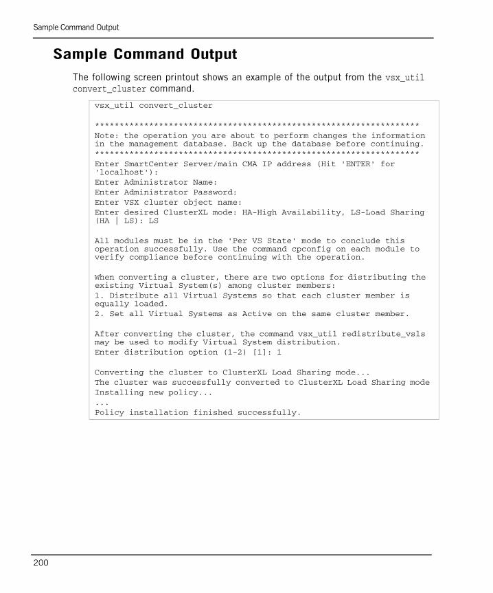
Sample Command Output
200
Sample Command OutputThe following screen printout shows an example of the output from the vsx_util convert_cluster command.
vsx_util convert_cluster
******************************************************************Note: the operation you are about to perform changes the information in the management database. Back up the database before continuing. ******************************************************************Enter SmartCenter Server/main CMA IP address (Hit 'ENTER' for 'localhost'): Enter Administrator Name: Enter Administrator Password: Enter VSX cluster object name: Enter desired ClusterXL mode: HA-High Availability, LS-Load Sharing (HA | LS): LS
All modules must be in the 'Per VS State' mode to conclude this operation successfully. Use the command cpconfig on each module to verify compliance before continuing with the operation.
When converting a cluster, there are two options for distributing the existing Virtual System(s) among cluster members:1. Distribute all Virtual Systems so that each cluster member is equally loaded.2. Set all Virtual Systems as Active on the same cluster member.
After converting the cluster, the command vsx_util redistribute_vsls may be used to modify Virtual System distribution.Enter distribution option (1-2) [1]: 1
Converting the cluster to ClusterXL Load Sharing mode...The cluster was successfully converted to ClusterXL Load Sharing modeInstalling new policy......Policy installation finished successfully.

Configuring VSX High Availability
Chapter 6 Managing VSX Clusters 201
Configuring VSX High AvailabilityThis section presents procedures for configuring VSX high availability features. In a VSX environment, you can work with one of two high availability modes:
VSX Gateway High Availability: Each cluster member functions as a VSX gateway and is synchronized with the other members. If a member goes down, it immediately fails over to another member. Likewise if an individual Virtual System, Virtual Router or Virtual Switch goes down, the entire member fails over to another member.
Per Virtual System High Availability: In the event that an individual Virtual System goes down, that Virtual System fails over to another member while all other Virtual Systems, together with other virtual devices, continue to function on the original member.
Enabling VSX Gateway High AvailabilityVSX gateway high availability is the default cluster configuration. If neither Per Virtual System nor Virtual System Load Sharing (VSLS) is active, a cluster functions in the VSX Gateway high availability mode. All members of a cluster must be configured to use the same clustering mode.
Configuring New Cluster MembersTo configure members for VSX gateway high availability, perform the following actions during the initial configuration phase (configsys):
1. Enter ‘y’ in response to the “Would you like to install a Check Point clustering product?” question to enable VSX clustering.
2. Enter ‘n’ when prompted to enable the Per Virtual System State.
3. Select the “ClusterXL
Configure all other properties according to your requirements.

Enabling Per Virtual System High Availability
202
Converting Existing Members to VSX Gateway HATo convert existing cluster members to the VSX gateway high availability mode, perform the following actions:
1. Execute the cpconfig command for each member and do the following:
a. Disable the Per Virtual System State for each member.
b. Disable ClusterXL for Bridge Active/Standby for each member.
2. Execute the vsx_util reconfigure command from the management server command line.
3. Re-initialize the members using the cpstop and cpstart commands.
Enabling Per Virtual System High AvailabilityThis section describes the procedures for enabling the Per Virtual System Failover in a high availability cluster.
Configuring New Cluster MembersTo configure members for Per Virtual System high availability, perform the following actions during the initial configuration phase:
1. Enter ‘y’ in response to the “Would you like to install a Check Point clustering product?” question to enable VSX clustering.
2. Enter ‘y’ when prompted to enable the Per Virtual System State.
3. Enter ‘n’ when prompted to enable Virtual System Load Sharing.
Configure all other properties according to your requirements.
Note - The following virtual devices are not supported when the Per Virtual System state is enabled:
- Virtual Routers
- Virtual Switches without physical or VLAN interfaces

Enabling Per Virtual System High Availability
Chapter 6 Managing VSX Clusters 203
Converting Existing Members to Per Virtual System HATo convert existing cluster members to the per Virtual System high availability mode, perform the following actions:
1. Execute the cpconfig command for each member and do the following:
a. Enable the Per Virtual System State for each member.
b. Disable ClusterXL for Bridge Active/Standby for each member.
2. Execute the vsx_util reconfigure command from the management server command line.
3. Re-initialize the members using the cpstop and cpstart commands.

Configuring Virtual System Load Sharing
204
Configuring Virtual System Load SharingThis section presents the various procedure for configuring VSLS deployments.
In This Section
Introduction Setting up VSLS for VSX requires first enabling Per Virtual System State mode on each cluster member. A Load Sharing cluster can then be created, either by creating a new cluster object, or converting an existing High Availability cluster to Load Sharing mode. Virtual Systems can then be modified as required.
Enable Per Virtual System State ModeThe Per Virtual System State mode enable active Virtual Systems to be placed on different cluster members, and for Virtual System-specific failover. This setting is mandatory for VSLS. On each cluster member, do the following:
1. Run cpconfig.
2. Select Enable Check Point Per Virtual System State.
3. Answer y to the question: Would you like to enable Per Virtual System state?
4. Reboot the machine.
Introduction page 204
Enable Per Virtual System State Mode page 204
Configuring Virtual System Load Sharing (VSLS) page 205
Distributing Virtual Systems Amongst Members page 206
Note - For existing VSLS clusters, you must upgrade all cluster members to the current version.
Note - The following virtual devices are not supported when the Per Virtual System state is enabled:
- Virtual Routers
- Virtual Switches that do not have physical or VLAN interfaces

Configuring Virtual System Load Sharing (VSLS)
Chapter 6 Managing VSX Clusters 205
Configuring Virtual System Load Sharing (VSLS)You can create VSLS clusters by one of two methods: as a new cluster, or by converting an existing high availability cluster.
Creating a New VSLS ClusterTo create a new cluster using VSLS, do the following:
1. From the Objects Tree in SmartDashboard, right click on Check Point and select New Check Point > VPN-1 Power VSX > Cluster. The VSX Cluster Wizard opens.
2. Configure the new cluster as described in “Creating a New Cluster” on page 172. On the General Properties page, select Check Point ClusterXL Virtual System Load Sharing from the VSX Cluster Platform list.
3. In the ClusterXL branch of the VSX Cluster Properties window, make certain that the Use State Synchronization option is enabled.
Converting a High Availability Cluster to VSLSTo convert existing high availability systems to VSLS, follow the procedures described in “Changing the Cluster Type” on page 199.
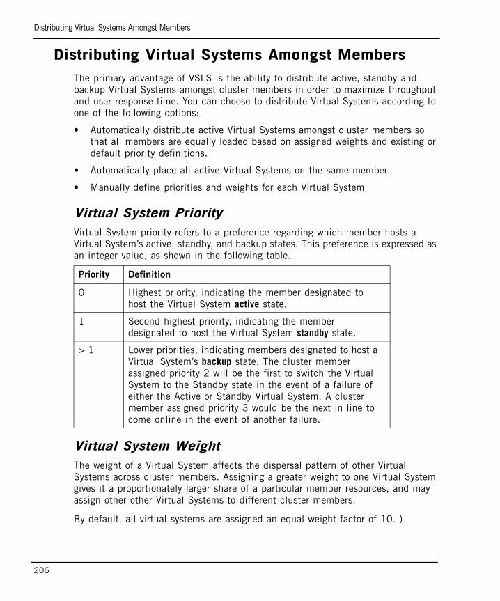
Distributing Virtual Systems Amongst Members
206
Distributing Virtual Systems Amongst MembersThe primary advantage of VSLS is the ability to distribute active, standby and backup Virtual Systems amongst cluster members in order to maximize throughput and user response time. You can choose to distribute Virtual Systems according to one of the following options:
• Automatically distribute active Virtual Systems amongst cluster members so that all members are equally loaded based on assigned weights and existing or default priority definitions.
• Automatically place all active Virtual Systems on the same member
• Manually define priorities and weights for each Virtual System
Virtual System PriorityVirtual System priority refers to a preference regarding which member hosts a Virtual System’s active, standby, and backup states. This preference is expressed as an integer value, as shown in the following table.
Virtual System WeightThe weight of a Virtual System affects the dispersal pattern of other Virtual Systems across cluster members. Assigning a greater weight to one Virtual System gives it a proportionately larger share of a particular member resources, and may assign other other Virtual Systems to different cluster members.
By default, all virtual systems are assigned an equal weight factor of 10. )
Priority Definition
0 Highest priority, indicating the member designated to host the Virtual System active state.
1 Second highest priority, indicating the member designated to host the Virtual System standby state.
> 1 Lower priorities, indicating members designated to host a Virtual System’s backup state. The cluster member assigned priority 2 will be the first to switch the Virtual System to the Standby state in the event of a failure of either the Active or Standby Virtual System. A cluster member assigned priority 3 would be the next in line to come online in the event of another failure.

Distributing Virtual Systems Amongst Members
Chapter 6 Managing VSX Clusters 207
Using the vsx_util redistribute_vsls CommandTo distribute Virtual Systems, perform the following steps:
1. Close SmartDashboard and/or the Provider-1 MDG.
2. Backup the management database.
3. Execute the vsx_util redistribute_vsls command. This is an interactive command script. Follow the instructions on the screen.
4. When the prompt “Enter redistribution option (1-3)appears, select the desired distribution option. Options 1 and 2 perform the Virtual System distribution automatically according to default priorities and weight factors. Option 3 allows you to define the priority and weight factor manually.
The following sections describe the procedures for completing the redistribution according to the selected option.
Distributing Virtual Systems for Equal Member Loading
To distribute Virtual Systems for equal member loading, continue as follows:
1. At the “Would you like to assign weights for the virtual systems?” prompt, enter ‘n’ to use the existing weights or ‘y’ to change the weights assigned to a Virtual System.
If you entered ‘n’ the redistribution process proceeds automatically with no further user intervention. If you entered ‘y’, continue with the next step.
2. At the “Would you like to [m]anually assign weights or use an existing configuration [f]ile?” prompt, enter ‘m’ to assign weights manually or ‘f’ to assign weights based on a saved configuration file.
If you entered ‘f’, enter the fully qualified path to the configuration file. The redistribution process proceeds automatically with no further user intervention. If you entered ‘m’, continue with the next step.
3. At the prompt for each Virtual System, enter an integer between 1 and 100 inclusive representing the Virtual System weight.
4. After you have entered the weight for all Virtual Systems, the redistribution process proceeds automatically with no further user intervention. Use the vsx_util vsls command to view and verify the distribution.
Note - Do not this command while the cluster is under heavy load, since the distribution process is a resource consuming task. Furthermore, in the event of a failover during redistribution, there is zero connectivity down-time, but existing connections may be lost.
Distributing Virtual Systems Amongst Members
208
Placing All Active Systems on the Same Member
The process continues automatically from this point without further user intervention. Priorities and weights are not taken into account for this type of distribution. Use the vsx_util vsls command to view and verify the distribution.
Manually Assigning Priorities and Weights for a Single Virtual System.
You can manually assign priorities and weights for individual Virtual Systems. If you wish to manually define multiple Virtual Systems, it is necessary to run the vsx_util redistribute_vsls command separately for each Virtual System.
To manually assign priorities and weights for individual Virtual Systems, continue as follows:
1. Enter the Virtual System name at the appropriate prompt.
2. At the “Would you like to change the virtual system's priority list?” prompt, enter ‘y’ to designate cluster member priorities for this Virtual System or enter ‘n’ to use the existing or default priority assignments.
If you entered ‘n’ proceed to step 5, otherwise continue with the next step.
3. Enter the number representing the member that you wish to host the active Virtual System (priority = 0).
4. If there are more the two members in the cluster, enter the number representing the member that you wish to host the standby Virtual System (priority =1). Continue assigning priorities to members hosting backup the Virtual Systems in this manner as required (priority >1). This step is only applicable if the cluster contains four or more members.
5. At the “Would you like to change the virtual system's weight?” prompt, enter ‘y’ to designate the weigh for this Virtual System or enter ‘n’ to use the existing weight.
If you entered ‘n’ the redistribution process continues automatically without further user intervention, otherwise continue with the next step.
6. At the prompt for each Virtual System, enter an integer between 1 and 100 inclusive representing the Virtual System weight.
7. After you have entered the weight for all Virtual Systems, the redistribution process proceeds automatically with no further user intervention. Use the vsx_util vsls command to view and verify the distribution.
8. Repeat this process for each Virtual System for which you wish to manually assign priorities and weights.
Configuring Virtual Systems in Bridge Mode
Chapter 6 Managing VSX Clusters 209
Configuring Virtual Systems in Bridge ModeIn This Section
OverviewThis section presents configuration information and procedures for Virtual Systems in the Bridge mode. By implementing native layer-2 bridging instead of IP routing, you can add Virtual Systems without affecting the existing IP structure.
When in the Bridge mode, Virtual System interfaces do not require IP addresses. You may optionally assign an IP address to the Virtual System itself (not the interfaces) to enable layer-3 monitoring. This feature enhances network fault detection.
VSX NGX R65 supports the following Bridge mode models:
• STP Bridge Mode: Provides redundancy while preventing undesirable loops between redundant switches.
• Active/Standby Bridge Mode: Provides path redundancy and loop prevention, while offering seamless support for Virtual System Load Sharing and overcoming many of the limitations of STP.
Overview page 209
STP Bridge Mode page 210
Active/Standby Bridge Mode page 212
STP Bridge Mode
210
STP Bridge Mode
In This Section
This section presents the procedures for enabling and configuring the STP Bridge mode for Virtual Systems and VSX gateways.
Defining the Spanning Tree StructureDefine and configure the Spanning Tree structure according to your network requirements. Please refer to your hardware documentation for the specific procedures for your network deployment.
Enabling STP Bridge Mode when Creating MemberWhen creating a new VSX gateway for use as a cluster member, configure the following cluster options during the initial configuration process (sysconfig or cpconfig):
1. Enter ‘y’ in response to the “Would you like to install a Check Point clustering product? question”.
2. Enter ‘n’, if prompted, to disable the Active/Standby Bridge mode. Continue with the remainder of the initial configuration process.
Enabling the STP Bridge Mode for Existing MembersTo enable the STP Bridge mode for existing cluster members, perform the following steps:
1. Execute the cpconfig command.
2. Enable cluster membership for this member (If a numerical value appears here, cluster membership has already been enabled).
3. Disable ClusterXL for Bridge Active/Standby.
4. Reboot the member.
Defining the Spanning Tree Structure page 210
Enabling STP Bridge Mode when Creating Member page 210
Enabling the STP Bridge Mode for Existing Members page 210
Configuring PVST+ Load Sharing page 211
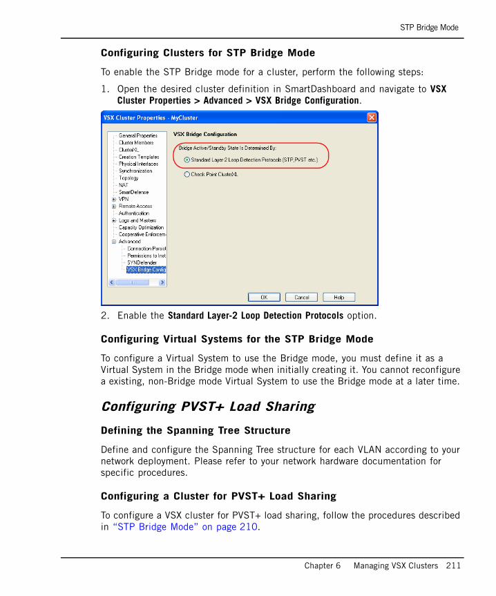
STP Bridge Mode
Chapter 6 Managing VSX Clusters 211
Configuring Clusters for STP Bridge Mode
To enable the STP Bridge mode for a cluster, perform the following steps:
1. Open the desired cluster definition in SmartDashboard and navigate to VSX Cluster Properties > Advanced > VSX Bridge Configuration.
2. Enable the Standard Layer-2 Loop Detection Protocols option.
Configuring Virtual Systems for the STP Bridge Mode
To configure a Virtual System to use the Bridge mode, you must define it as a Virtual System in the Bridge mode when initially creating it. You cannot reconfigure a existing, non-Bridge mode Virtual System to use the Bridge mode at a later time.
Configuring PVST+ Load Sharing
Defining the Spanning Tree Structure
Define and configure the Spanning Tree structure for each VLAN according to your network deployment. Please refer to your network hardware documentation for specific procedures.
Configuring a Cluster for PVST+ Load Sharing
To configure a VSX cluster for PVST+ load sharing, follow the procedures described in “STP Bridge Mode” on page 210.

Active/Standby Bridge Mode
212
Active/Standby Bridge ModeThis section presents the procedures for enabling and configuring the Active/Standby Bridge mode for Virtual Systems and VSX gateways.
Enabling and Configuring Active/Standby Bridge Mode
In This Section
Enabling Active/Standby Bridge Mode for a New Member
When creating a new cluster member, enable the following cluster options during the initial configuration (sysconfig or cpconfig) process:
1. Enter ‘y’ in response to the “Would you like to install a Check Point clustering product? question”.
2. If you enable the Per Virtual System State feature, which is required for VSLS, the Active/Standby Bridge mode is enabled automatically, and no further action is necessary.
3. If you elected not to enable VSLS, an option to enable the Active/Standby Bridge mode feature appears. Enter ‘y’ and continue with the remainder of the gateway initial configuration process.
Enabling Active/Standby Bridge Mode for a New Member page 212
Enabling Active/Standby Bridge Mode for Existing Members page 213
Configuring Clusters for Active/Standby Bridge Mode page 213
Configuring Virtual Systems for Active/Standby Bridge Mode page 214

Active/Standby Bridge Mode
Chapter 6 Managing VSX Clusters 213
Enabling Active/Standby Bridge Mode for Existing Members
To enable the Active/Standby Bridge mode on existing Virtual Systems, perform the following steps:
1. Run the cpconfig command.
2. Enable ClusterXL for Bridge Active/Standby
3. Reboot the member
Configuring Clusters for Active/Standby Bridge Mode
To enable the Active/Standby Bridge mode for a cluster, perform the following steps:
1. Open the cluster definition in SmartDashboard and navigate to VSX Cluster Properties > Advanced > VSX Bridge Configuration.
2. Enable the Check Point ClusterXL option, which enables the Active/Standby Bridge mode loop detection algorithms contained in ClusterXL.

Active/Standby Bridge Mode
214
Configuring Virtual Systems for Active/Standby Bridge Mode
To configure a Virtual System to use the Bridge mode, you must define it as a Virtual System in the Bridge mode when initially creating it. You cannot reconfigure a existing, non-Bridge mode Virtual System to use the Bridge mode at a later time.
Perform the following steps to configure a Virtual System for the Active/Standby Bridge mode:
1. On the Virtual System Wizard - General Properties page, enable the Bridge mode option.
2. On the Network Configuration page, Click Add to open the Add Interface window. Define an internal and external interface as follows:
a. Select an interface from the list.
b. Enter a unique VLAN tag.
c. Select either an internal or external interface.
d. For internal interfaces, optionally select an IP address or Network that connects to the interface.
3. Optionally, enable Layer-3 bridge interface monitoring. This feature assists in detecting network faults for failover. The IP address must be unique and be located on the same subnet as the protected network.

Advanced Clustering Configuration
Chapter 6 Managing VSX Clusters 215
Advanced Clustering ConfigurationThis section presents several advanced cluster scenarios and procedures for their configuration.
Clusters on the Same Layer-2 SegmentThe recommended cluster architecture contains interfaces connect to a Layer-2 segment that is isolated from other clusters. When configuring a cluster with only two members, you should connect the secured interfaces of the sync network using a crossover cable.
However, in a deployment where multiple clusters need to connect to the same Layer-2 segment, the same MAC address may be used by more than one cluster for Cluster Control Protocol (CCP) communication. This may direct traffic to the incorrect cluster. In this case you will need to modify the source MAC address(es) of the clusters.
This section describes how source MAC addresses are assigned, and explains how to change them. This procedure applies to both ClusterXL and OPSEC certified clustering products using the High Availability mode.
Source Cluster MAC AddressesCluster members use CCP to communicate with each other. In order to distinguish CCP packets from ordinary network traffic, CCP packets are given a unique source MAC address.
• The first four bytes of the source MAC address are all zero: 00.00.00.00
• The fifth byte of the source MAC address is a “magic” number, a number that encodes critical information in a way intended to be opaque. Its value indicates its purpose:
• The sixth byte is the ID of the source cluster member
When multiple clusters are connected to the same Layer-2 segment, setting a unique value to the fifth byte of the MAC source address of each cluster allows them to coexist on the same Layer-2 segment.
Default value of fifth byte Purpose
0xfe CCP traffic
0xfd Forwarding layer traffic

Clusters on the Same Layer-2 Segment
216
Changing a Cluster’s MAC Source Address
To change a cluster’s MAC source address, run the following commands on each cluster member:
The default values of the parameters fwha_mac_magic and fwha_mac_forward_magic appear in the following table:
Use any value as long as the two gateway configuration parameters are different. To avoid confusion, do not use the value 0x00.
Making the Change Permanent
You can configure the above configuration parameters to persist following reboot. For SecurePlatform machines, perform the following steps:
1. Use a text editor to open the file fwkern.conf, located at $FWDIR/boot/modules/.
2. Add the line Parameter=<value in hex>. Make sure there are no spaces.
fw ctl set int fwha_mac_magic <value>
fw ctl set int fwha_mac_forward_magic <value>
Parameter Default value
fwha_mac_magic 0xfe
fwha_mac_forward_magic 0xfd

Monitoring all VLANs with ClusterXL
Chapter 6 Managing VSX Clusters 217
Monitoring all VLANs with ClusterXLBy default, ClusterXL only monitors two VLANS for failure detection and failover. These are the highest and lowest VLAN tags defined for a given interface.
For example, if the topology for interface eth1 includes several VLAN tags in the range of eth1.10 to eth1.50, ClusterXL only monitors VLANs eth1.10 and eth1.50 for failure. Failures on any of the other VLANs are not detected in the default configuration.
When both the highest and lowest VLANs fail, all the VLANs are considered down, and a failover occurs. This means that if a VLAN which is not listed as the highest or lowest goes down, the trunk is still considered “up”, and no failover occurs.
There are instances in which it would be advantageous to monitor all the VLANs in the trunk, not just the highest and lowest, and initiate a failover when any one of the VLANs goes down.
To enable monitoring of all VLANs, enable the fwha_monitor_all_vlans property in $FWDIR/boot/modules/fwkern.conf.
Note - The command line option cphaprob -a if displays the highest and lowest VLANs being monitored.
Note - Monitoring all VLANS is enabled automatically when the Per VLAN state option is enabled.
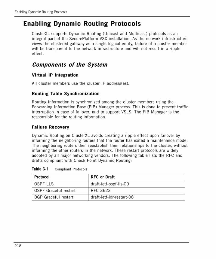
Enabling Dynamic Routing Protocols
218
Enabling Dynamic Routing ProtocolsClusterXL supports Dynamic Routing (Unicast and Multicast) protocols as an integral part of the SecurePlatform VSX installation. As the network infrastructure views the clustered gateway as a single logical entity, failure of a cluster member will be transparent to the network infrastructure and will not result in a ripple effect.
Components of the System
Virtual IP Integration
All cluster members use the cluster IP address(es).
Routing Table Synchronization
Routing information is synchronized among the cluster members using the Forwarding Information Base (FIB) Manager process. This is done to prevent traffic interruption in case of failover, and to support VSLS. The FIB Manager is the responsible for the routing information.
Failure Recovery
Dynamic Routing on ClusterXL avoids creating a ripple effect upon failover by informing the neighboring routers that the router has exited a maintenance mode. The neighboring routers then reestablish their relationships to the cluster, without informing the other routers in the network. These restart protocols are widely adopted by all major networking vendors. The following table lists the RFC and drafts compliant with Check Point Dynamic Routing:
Table 6-1 Compliant Protocols
Protocol RFC or Draft
OSPF LLS draft-ietf-ospf-lls-00
OSPF Graceful restart RFC 3623
BGP Graceful restart draft-ietf-idr-restart-08

Enabling Dynamic Routing Protocols
Chapter 6 Managing VSX Clusters 219
Dynamic Routing in ClusterXLThe components listed above function “behind-the-scenes.” When configuring Dynamic Routing on ClusterXL, the routing protocols automatically relate to the cluster as they would to a single device.
When configuring the routing protocols on each cluster member, each member is defined identically, and uses the cluster IP address(es) (not the member’s physical IP address). In the case of OSPF, the router ID must be defined and identical on each cluster member. When configuring OSPF restart, you must define the restart type as signaled or graceful. For Cisco devices, use type signaled.
Use SecurePlatform’s command line interface to configure each cluster member. Table 6-2 is an example of the proper syntax for cluster member A.
Table 6-2 Enabling OSPF on cluster member A
--------- Launch the Dynamic Routing Modulevsx1:0]# routerER0 999 Unable to connect to host 'localhost'!ER0 999 Dynamic Routing is not supported on VSX gateway/clusterUse 'vrf-connect' to enter specific Virtual System(disconnected)>vrf-connect 1localhost.localdomain- VRF-1>enablelocalhost.localdomain- VRF-1#configure terminal
--------- Enable OSPF and provide an OSPF router IDlocalhost.localdomain- VRF-1(config)#router ospf 1localhost.localdomain- VRF-1(config-router-ospf)#router-id 192.168.116.10localhost.localdomain- VRF-1(config-router-ospf)#restart-type [ graceful | signaled ]localhost.localdomain- VRF-1(config-router-ospf)#redistribute kernel
--------- Define interfaces/IP addresses on which OSPF runs (Use the cluster IPlocalhost.localdomain- VRF-1(config-router-ospf)#network 1.1.10.10 0.0.0.0 area 0.0.0.0localhost.localdomain- VRF-1(config-router-ospf)#network 1.1.10.20 0.0.0.0 area 0.0.0.0
-------- Exit the Dynamic Routing Modulelocalhost.localdomain- VRF-1(config-router-ospf)#exitlocalhost.localdomain- VRF-1(config)#exit -------- Write configuration to disklocalhost.localdomain- VRF-1#write memoryIU0 999 Configuration written to '/etc/gated1.ami'localhost.localdomain- VRF-1#

Enabling Dynamic Routing Protocols
220
The same configuration needs to be applied to each cluster member.
As the FIB Manager uses TCP 2010 for routing information synchronization, the Security Policy must accept TCP 2010 to and from all cluster members. This is enabled as an implied rule.
For detailed information regarding Dynamic Routing, see the Check Point Advanced Routing Suite guide.
221
Chapter 7Optimizing VSX
In This Chapter
VSX Resource Control page 222
QoS Enforcement page 228

VSX Resource Control
222
VSX Resource ControlIn This Section
OverviewVSX Resource Control allows administrators to ensure that critical traffic receives a greater share of the available VSX gateway or cluster member processing power by assigning priorities to each Virtual System. Since individual networks protected by Virtual Systems have differing traffic loads, user demand, and criticality, allocating available CPU resources to individual Virtual Systems according to predetermined priorities is an important consideration in any VSX deployment.
By using VSX Resource Control, administrators can allocate CPU resources to individual Virtual Systems according to specific requirements. Virtual Systems protecting mission critical networks or resource intensive applications are assigned higher priorities and are ensured a greater share of CPU resources. Virtual Systems with lower priorities are guaranteed a lesser CPU share.
In addition, VSX Resource Control performs the following actions:
• Ensures that each Virtual System receives a minimum CPU allocation and that no Virtual System can deny another Virtual System access to the CPU
• Makes CPU resources not required by Virtual Systems to which they are allocated available for use by other Virtual Systems, until they are needed
VSX Resource Control can only manage available CPU resources, meaning those CPU resources that are not required by other processes running on the VSX gateway. If the operating system, check point products and other application processes consume 40% of CPU resources, VSX Resource Control can only manage the remaining 60%.
Overview page 222
Resource Control System Components page 223
Virtual System Priorities page 224

Resource Control System Components
Chapter 7 Optimizing VSX 223
Resource Control System ComponentsResource Control has two principal components:
• The Resource Control Monitor keeps track of the CPU consumption of each Virtual System. It also provides real-time information on the present and average CPU consumption by the Virtual Systems on the VSX machine.
• The Resource Control Enforcer implements the Resource Policy. The Resource Control Enforcer utilizes the data collected by the Resource Control Monitor to implement the Resource Policy.
Note - You must enable the Resource Control Monitor in order to use the Resource Control Enforcer. You can, however, activate the monitor without the enforcer if only wish to monitor CPU utilization.
Virtual System Priorities
224
Virtual System PrioritiesVSX Resource Control uses a weight factor to assign priorities to Virtual Systems. The weight factor is expressed as an integer between one and 100, that indicates a particular Virtual System’s priority in relation to other Virtual Systems. Virtual Routers and Virtual Switches are automatically assigned to priority and their priorities are not modifiable.
The Default Weight FactorEach new or undefined Virtual System receives a default weight to 10 by default. This means that they are entitled to an equal proportion of available CPU Resources. For example, on a VSX gateway containing five Virtual Systems with the default weight factor of 10, each is guaranteed at least 20% of the available CPU resources. Adding five more Virtual Systems with default weights to this same gateway would guarantee each Virtual System a minimum of 10% of the available resources.
User Defined WeightsTo assign different priorities to individual Virtual Systems, you must manually assign a weight factor to each. The percentage of CPU resources guaranteed to a particular Virtual System is determined by dividing its weight by the total weight of all Virtual Systems on the VSX Gateway or cluster.
For example, if Virtual System A is assigned a weight of 40, and the total weight of all Virtual Systems (including Virtual System A) is 80, then Virtual System A is guaranteed a minimum of 50% of the available CPU resources..
Note - As long as the VSX gateway has available CPU resources, each Virtual System receives some resources regardless of its weight. When a system is under stress, however, Virtual Systems with the lower weights will be the first to be affected by the lack of CPU resources.

Working with VSX Resource Control
Chapter 7 Optimizing VSX 225
Working with VSX Resource ControlThis section presents procedures for enabling and disabling VSX Resource Control, for assigning Virtual System priorities and for monitoring CPU resource utilization. VSX Resource Control is disabled by default. You can
Enabling VSX Resource Control ComponentsTo enable VSX Resource Control enforcement, execute the vsx resctrl enforce enable command. This command starts both the Resource Control Enforcer and the Resource Control Monitor.
To enable the Resource Control Monitor without enforcement, execute the vsx resctrl monitor enable command.
Disabling VSX Resource Control ComponentsTo enable VSX Resource Control enforcement, execute the vsx resctrl enforce command. This command starts both the Resource Control Enforcer and the Resource Control Monitor.
To disable the Resource Control Enforcer, execute the vsx resctrl enforce disable command.
To disable the Resource Control Monitor, execute the vsx resctrl monitor disable command.
You execute each command separately.
Note - The vsx resctrl enforce and vsx resctrl monitor commands work for the current session only. Upon reboot, Resource Control is automatically enabled or disabled according to settings in the Resource Control configuration file.

Working with VSX Resource Control
226
Assigning Priorities to Virtual SystemsAssigning Virtual System priorities requires editing the Resource Control configuration file $FWDIR/conf/resctrl on the VSX gateway or on each cluster member. The following information appears in the configuration file:
• Resource Control Monitor default setting (enabled/disabled). This if
• Resource Control Enforcer default setting (enabled/disabled)
• Manually assigned Virtual System weight factors. Virtual Systems using the default weight factor (10) do not appear in the configuration file.
A sample configuration file appears below:
To manually assign Virtual System priorities, perform the following steps:
1. Open the $FWDIR/conf/resctrl file using a text editor.
2. Change the monitoring and enforcement default setting to enabled. This ensures that the Resource Control enforcer is active by default whenever the VSX Gateway or cluster member is rebooted.
3. For each Virtual System, enter its Virtual System ID (vsid) followed by a space and its weight factor (an integer between 1 and 100 inclusive). Each Virtual System must appear on a separate line, as illustrated in the above example.
4. Save and close the configuration file.
5. Execute the vsx resctrl start command.
6. Execute the vsx resctrl stat command to verify the configuration.
#file format:#first line must be "monitoring enabled" or "monitoring disabled"#second line must be "enforcement enabled" or "enforcement disabled"#rest of the lines should contain weights for the virtual systems where#weight varies between 1 and 100#<vsid> <weight>#For example:#8 40
monitoring enabledenforcement enabled2 253 404 15
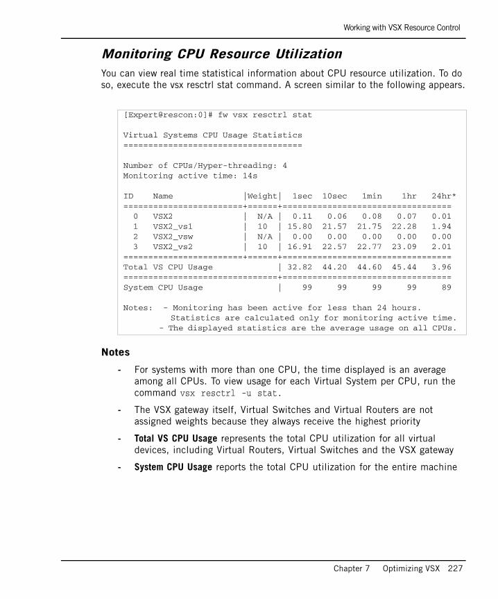
Working with VSX Resource Control
Chapter 7 Optimizing VSX 227
Monitoring CPU Resource UtilizationYou can view real time statistical information about CPU resource utilization. To do so, execute the vsx resctrl stat command. A screen similar to the following appears.
Notes
- For systems with more than one CPU, the time displayed is an average among all CPUs. To view usage for each Virtual System per CPU, run the command vsx resctrl -u stat.
- The VSX gateway itself, Virtual Switches and Virtual Routers are not assigned weights because they always receive the highest priority
- Total VS CPU Usage represents the total CPU utilization for all virtual devices, including Virtual Routers, Virtual Switches and the VSX gateway
- System CPU Usage reports the total CPU utilization for the entire machine
[Expert@rescon:0]# fw vsx resctrl stat
Virtual Systems CPU Usage Statistics====================================
Number of CPUs/Hyper-threading: 4Monitoring active time: 14s
ID Name |Weight| 1sec 10sec 1min 1hr 24hr*========================+======+================================== 0 VSX2 | N/A | 0.11 0.06 0.08 0.07 0.01 1 VSX2_vs1 | 10 | 15.80 21.57 21.75 22.28 1.94 2 VSX2_vsw | N/A | 0.00 0.00 0.00 0.00 0.00 3 VSX2_vs2 | 10 | 16.91 22.57 22.77 23.09 2.01========================+======+==================================Total VS CPU Usage | 32.82 44.20 44.60 45.44 3.96===============================+==================================System CPU Usage | 99 99 99 99 89
Notes: - Monitoring has been active for less than 24 hours. Statistics are calculated only for monitoring active time. - The displayed statistics are the average usage on all CPUs.

QoS Enforcement
228
QoS Enforcement
OverviewQoS Enforcement for VSX provides the ability to control the network quality of service in the VSX network environment. QoS is based on the Differentiated Services architecture and allows assigning different transmission characteristics to different classes of service.
Differentiated Services is a computer networking architecture that specifies a simple, scalable and coarse-grained mechanism for classifying, managing network traffic and providing quality of service (QoS) guarantees on modern IP networks. Differential services can, for example, be used to provide low-latency, guaranteed service (GS) to critical network traffic such as voice or video while providing simple best-effort traffic guarantees to non-critical services such as web traffic or file transfers.
The major characteristics that are controllable by QoS are latency and bandwidth allocation. QoS is designed to provide QoS functionality with minimal impact on performance. QoS works seamlessly with Check Point Performance Pack.
The VSX network usually includes various types of traffic such as:
• Real-time traffic (e.g. VoIP) which requires low bandwidth, and is sensitive to latency (delays) and drops
• Traffic which is sensitive to latency but not to occasional drops
• High-volume, low-priority traffic which has a low sensitivity to latency and drops
• Other traffic which requires its own share of the bandwidth
Without QoS Enforcement, all these different traffic types are given equal priority on the VSX gateway and are handled in a simple FIFO (first in-first out) manner. When the VSX gateway is congested, all traffic types suffer the same degree of latency and drops. Also, high-volume traffic may starve other types of low-volume traffic.
With QoS, the special requirements of each traffic type can be met. For example:
• Latency-sensitive traffic will be given preference over other types of traffic
• Traffic which is sensitive to drops will suffer fewer drops than other types of traffic.

Architecture
Chapter 7 Optimizing VSX 229
• High-volume traffic that consumes bandwidth will be limited during times of congestion.
ArchitectureThree major aspects of the QoS architecture are:
• Differentiated Services support
• Inbound prioritization
• Policy with a global scope
Differentiated Services SupportQoS provides basic support for Differentiated Services, an architecture for specifying and controlling network traffic by class so that certain types of traffic receive priority over others. The differentiated services architecture PHB's (per-hop behaviors).
When marked packets arrive to the VSX machine, they are classified and prioritized according to their DSCP (differential services code-point) values. To enhance performance, QoS does not mark packets with DSCP and does not change their Type of Service (ToS) values. QoS instead relies on peripheral devices (namely routers) to mark packets with the appropriate ToS value.
Inbound PrioritizationWhile Differentiated Services support in routers is usually performed on outbound traffic, QoS for VSX prioritizes traffic on the inbound side because, in VSX deployments, QoS is primarily governed by system resources, namely the CPU, and not by network bandwidth.
To prevent the VSX machine from becoming a bottleneck in the network, prioritization is enforced when packets arrive at the VSX machine, and before CPU processing is assigned.
Inbound prioritization allows an earlier control on the loss and delay rate.
Note - QoS requires the use of DiffServ-enabled routers to mark preferred traffic types with a special tag. The tag is the DSCP (DiffServ Code Point), which represents the six most significant bits of the IP header's TOS field, as described in RFC 2474. The VSX gateway should then be configured to give traffic with this tag the required priority.
QoS Features
230
Policy with Global ScopeTo minimize the impact of QoS functionality on performance, QoS is not performed on a per interface basis, but for the entire system. This means that a certain class of service will apply to all traffic entering the VSX gateway or cluster, regardless of the specific interface from which the traffic originates.
QoS FeaturesTwo main features of QoS are:
• Resource allocation
• Latency control
Resource AllocationSystem resources are allocated by assigning different weights to different classes of service. A weight is the relative portion of the available resources allocated to a class. Allocating resources according to weights ensures full utilization of the line even if a specific class is not using all of its resources. In such a case, the remaining resources are divided among the remaining classes in accordance with their relative weights.
LatencyFor some types of traffic, such as voice and video, it is necessary to minimize the latency (delay) of packets. Latency is controlled by defining special LLQ (low-latency queueing) classes. These classes are handled in a strict priority manner. LLQ packets are handled immediately upon arrival, and before packets that do not belong to LLQ classes.
QoS supports multiple LLQ classes. In some cases, it may be necessary to define more than one Low Latency class, for example when different types of traffic have a different sensitivity to delays. In such cases, a class with the higher sensitivity to delay receives a higher priority than a class with the lower sensitivity.
Note - On multiple-CPU machines, enforcement is not performed system-wide, but executed per-CPU. This means that global enforcement is done separately on traffic processed by each CPU.
Note - When LLQ classes are used, it is assumed that the expected traffic will not exceed a relatively small amount of the available resources. Although QoS does not allow LLQ traffic to starve non-LLQ traffic, too much LLQ traffic reduces overall network quality of service and prevents efficient management of weighted resources.

QoS Management
Chapter 7 Optimizing VSX 231
WREDRED (Random Early Drop) is a congestion avoidance mechanism for detecting and preventing congestions. It takes advantage of TCP's congestion control mechanism by randomly dropping packets during periods of congestion. This causes TCP senders to slow down their transmission, thus preventing high congestion.
QoS implements WRED (Weighted RED) in which packets are dropped according to their priority. WRED mostly affects traffic which is of low priority and which exceeds its weight.
QoS ManagementTo manage the network quality of service it is necessary to create and install a QoS policy. The QoS policy consists of a list of up to 15 classes of service. Each class is assigned certain traffic characteristics and DSCP values.
The QoS policy is managed with the cpqos command. For cpqos command usage, see: See “QoS Configuration” on page 233.
Class of Service DefinitionsThe definition of a class of service includes the following:
• Name. The class name is a unique identifier which identifies the class during configuration and when presenting statistics
• Type. There are two types of classes, LLQ and regular classes. Regular classes are non-LLQ classes which can be assigned a weight value.
• Priority. Each class is assigned a unique priority value between 1 and 15. The priority value is effective in prioritizing LLQ classes and during congestion, when drops occur.
• Weight value. Each class is assigned a specific weight value
• One or more DSCP values. The Differentiated Services code point
Priority and LLQsIf there are multiple LLQ classes, packets are handled in a strict priority-based manner. Packets from a class with a higher priority are handled before packets with a lower priority class.

QoS Management
232
Priority and Drop PrecedencePriority also determines the probability of drops. A class with a lower priority has a higher drop precedence during times of congestion.
The class priority is not the only factor that determines if drops occur. Other factors affect drops, for example if the class is LLQ or if the class exceeds its assigned resource allocation.
LLQ's are not immune to drops. Although LLQ's are processed as soon as they arrive (and thus have a lower drop rate), drops may occur if there are many LLQ classes or if a large portion of the incoming traffic is LLQ.
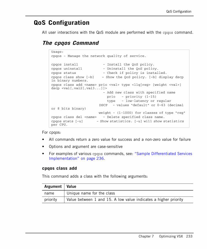
QoS Configuration
Chapter 7 Optimizing VSX 233
QoS ConfigurationAll user interactions with the QoS module are performed with the cpqos command.
The cpqos Command
For cpqos:
• All commands return a zero value for success and a non-zero value for failure
• Options and argument are case-sensitive
• For examples of various cpqos commands, see: “Sample Differentiated Services Implementation” on page 236.
cpqos class add
This command adds a class with the following arguments:
Usage:cpqos - Manage the network quality of service.
cpqos install - Install the QoS policy.cpqos uninstall - Uninstall the QoS policy.cpqos status - Check if policy is installed.cpqos class show [-b] - Show the QoS policy. [-b] display dscp in binary numbers.cpqos class add <name> prio <val> type <llq|reg> [weight <val>] dscp <val[,val2[,val3...]]> - Add new class with specified name prio - priority (1-15) type - low-latency or regular DSCP - values "default" or 0-63 (decimal or 8 bits binary) weight - (1-1000) for classes of type "reg"cpqos class del <name> - Delete specified class name.cpqos stats [-u] - Show statistics. [-u] will show statistics per CPU.
Argument Value
name Unique name for the class
priority Value between 1 and 15. A low value indicates a higher priority

QoS Configuration
234
cpqos class del
This command deletes the class of the specified name. Changes to the policy with cpqos class del are enforced only after the policy is installed.
cpqos class show
This command shows the classes defined in the QoS policy.
cpqos install
This command installs the previously created QoS policy. It also validates the overall integrity of the policy. Once installed, the policy remains installed even if the machine reboots.
cpqos uninstall
This command un-installs the previously installed QoS policy. If un-installed, the policy will not be installed again when the machine boots.
type “llq” for low-latency classes or “reg” for regular, weighted classes
weight This value is used only for classes of type “reg”. It determines the relative portion of the resources that the class will receive in relation to other weighted classes. Valid values are between 0 and 1000.
dscp The DiffServ code-points assigned to the class. Multiple DSCP's can be specified, separated by commas, with no spaces between values. Values are in decimal (not binary format) with values from 0 to 63 or “default”. There can be only one class with a “default” DSCP.
The default class is used for traffic without DiffServ marking (e.g. tos=0) or traffic with DSCP values that are not assigned to any other class. If no class is used as “default”, all 64 DSCP values must be assigned to the classes. A DSCP value cannot be assigned to more than one class.
Argument Value
Note - Changes to the policy with cpqos class add are enforced only after the policy is installed.

QoS Configuration
Chapter 7 Optimizing VSX 235
cpqos stats
This command shows QoS statistics. cpqos stats prints a line of statistics for each of the defined classes. Each line includes the following data columns:
Note:
• [-c] option shows statistics separately for each CPU
• Statistics values are byte-counts, not packet counts
• Statistics values are reset after each query.
• Statistics should be presented periodically with intervals less than 1 minute.
• It is recommended to use the watch command to periodically present the statistics.
QoS Policy FileThe QoS policy file is qos_policy.C, located in the $FWDIR/database directory. The QoS policy file is created when the cpqos command is run for the first time. The QoS policy file should not be edited manually. Use cpqos class add/del to create entries. To maintain multiple QoS policies, rename qos_policy.C or copy it to another directory, and copy it back to $FWDIR/database/qos_policy.C when the policy needs to be enforced.
QoS Default ConfigurationDefault QoS configuration is set to “uninstall” (e.g. not enforced). Calling cpqos install or cpqos uninstall sets the default configuration after boot
Column Value
rx Number of bytes that arrived to this class since the last time statistics were presented
tx Number of bytes that were transmitted from this class since the last time statistics were presented
drops Number of bytes that were dropped from this class since the last time statistics were presented
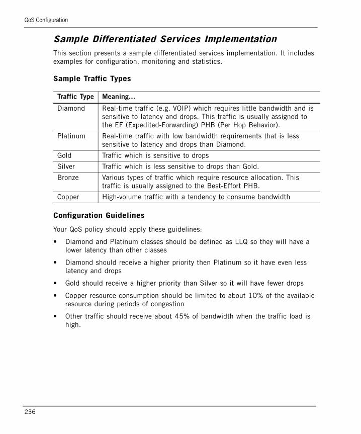
QoS Configuration
236
Sample Differentiated Services ImplementationThis section presents a sample differentiated services implementation. It includes examples for configuration, monitoring and statistics.
Sample Traffic Types
Configuration Guidelines
Your QoS policy should apply these guidelines:
• Diamond and Platinum classes should be defined as LLQ so they will have a lower latency than other classes
• Diamond should receive a higher priority then Platinum so it have even less latency and drops
• Gold should receive a higher priority than Silver so it will have fewer drops
• Copper resource consumption should be limited to about 10% of the available resource during periods of congestion
• Other traffic should receive about 45% of bandwidth when the traffic load is high.
Traffic Type Meaning...
Diamond Real-time traffic (e.g. VOIP) which requires little bandwidth and is sensitive to latency and drops. This traffic is usually assigned to the EF (Expedited-Forwarding) PHB (Per Hop Behavior).
Platinum Real-time traffic with low bandwidth requirements that is less sensitive to latency and drops than Diamond.
Gold Traffic which is sensitive to drops
Silver Traffic which is less sensitive to drops than Gold.
Bronze Various types of traffic which require resource allocation. This traffic is usually assigned to the Best-Effort PHB.
Copper High-volume traffic with a tendency to consume bandwidth
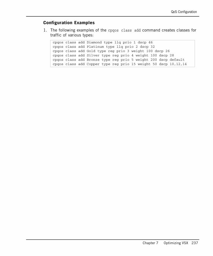
QoS Configuration
Chapter 7 Optimizing VSX 237
Configuration Examples
1. The following examples of the cpqos class add command creates classes for traffic of various types:
cpqos class add Diamond type llq prio 1 dscp 46cpqos class add Platinum type llq prio 2 dscp 32cpqos class add Gold type reg prio 3 weight 100 dscp 26cpqos class add Silver type reg prio 4 weight 100 dscp 28cpqos class add Bronze type reg prio 5 weight 200 dscp defaultcpqos class add Copper type reg prio 15 weight 50 dscp 10,12,14

QoS Configuration
238
2. Monitoring example. The following command lists the previously defined classes:
[Expert@cpmodule:0]# cpqos class show
class: Diamond priority: 1 type: llq weight: 0 DSCPs: 46
class: Platinum priority: 2 type: llq weight: 0 DSCPs: 32
class: Gold priority: 3 type: reg weight: 100 DSCPs: 26
class: Silver priority: 4 type: llq weight: 100 DSCPs: 28
class: Bronze priority: 5 type: llq weight: 200 DSCPs: default
class: Copper priority: 15 type: reg weight: 50 DSCPs: 10,12,14

QoS Configuration
Chapter 7 Optimizing VSX 239
3. Statistics example. The following command lists statistics for the previously defined classes:
From this statistical output, it is apparent that:
• In the Diamond class there were no drops.
• In the Platinum class there were a few drops, even though less traffic arrived classed as Platinum than did as Diamond.
• In the Gold class there were fewer drops than from the Silver class.
• In the Bronze class there were twice as many bytes transmitted than in the Silver and Gold classes, and four times as many bytes than there were in the Copper class.
• Most packets in the Copper class were dropped.
[Expert@cpmodule:0]# cpqos stats
class prio type weight rx tx dropsDiamond 1 llq 0 2775 2650 0Platinum 2 llq 0 1024 1020 105Gold 3 reg 100 1775015 1773805 205Silver 4 reg 100 1862437 1862336 550Bronze 5 reg 200 3370033 2955120 3147Copper 15 reg 50 1862437 762336 100689
QoS Configuration
240
241
Chapter 8Deploying VSX
In This Chapter
IntroductionThis chapter presents deployment concepts and strategies for exploiting VSX virtualization and its unique feature set. This presentation is divided into two sections as follows:
• Internal Network Protection Strategies: Presents concepts and examples for protecting internal network resources, including a comparison between physical deployments and VSX virtualization.
• Organizational Deployment Strategies: Presents VSX deployment strategies and features for several different types of large organizations.
Introduction page 241
Internal Network Deployment Strategies page 242
Organizational Deployment Strategies page 252
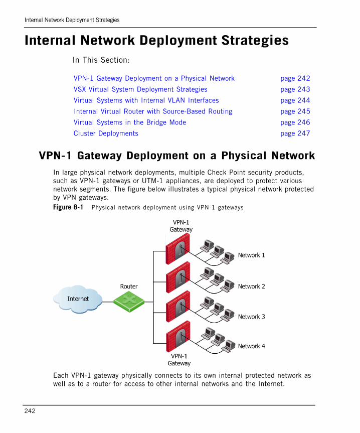
Internal Network Deployment Strategies
242
Internal Network Deployment StrategiesIn This Section:
VPN-1 Gateway Deployment on a Physical NetworkIn large physical network deployments, multiple Check Point security products, such as VPN-1 gateways or UTM-1 appliances, are deployed to protect various network segments. The figure below illustrates a typical physical network protected by VPN gateways. Figure 8-1 Physical network deployment using VPN-1 gateways
Each VPN-1 gateway physically connects to its own internal protected network as well as to a router for access to other internal networks and the Internet.
VPN-1 Gateway Deployment on a Physical Network page 242
VSX Virtual System Deployment Strategies page 243
Virtual Systems with Internal VLAN Interfaces page 244
Internal Virtual Router with Source-Based Routing page 245
Virtual Systems in the Bridge Mode page 246
Cluster Deployments page 247
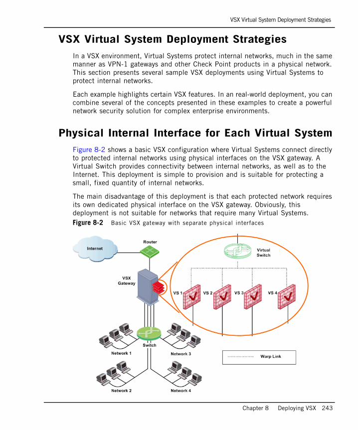
VSX Virtual System Deployment Strategies
Chapter 8 Deploying VSX 243
VSX Virtual System Deployment StrategiesIn a VSX environment, Virtual Systems protect internal networks, much in the same manner as VPN-1 gateways and other Check Point products in a physical network. This section presents several sample VSX deployments using Virtual Systems to protect internal networks.
Each example highlights certain VSX features. In an real-world deployment, you can combine several of the concepts presented in these examples to create a powerful network security solution for complex enterprise environments.
Physical Internal Interface for Each Virtual SystemFigure 8-2 shows a basic VSX configuration where Virtual Systems connect directly to protected internal networks using physical interfaces on the VSX gateway. A Virtual Switch provides connectivity between internal networks, as well as to the Internet. This deployment is simple to provision and is suitable for protecting a small, fixed quantity of internal networks.
The main disadvantage of this deployment is that each protected network requires its own dedicated physical interface on the VSX gateway. Obviously, this deployment is not suitable for networks that require many Virtual Systems.Figure 8-2 Basic VSX gateway with separate physical interfaces
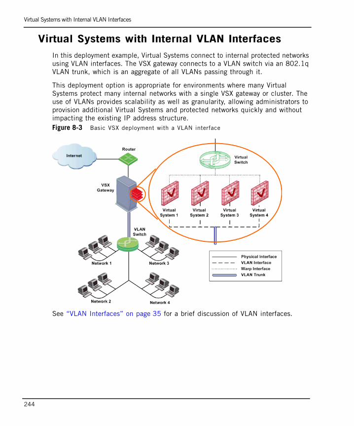
Virtual Systems with Internal VLAN Interfaces
244
Virtual Systems with Internal VLAN InterfacesIn this deployment example, Virtual Systems connect to internal protected networks using VLAN interfaces. The VSX gateway connects to a VLAN switch via an 802.1q VLAN trunk, which is an aggregate of all VLANs passing through it.
This deployment option is appropriate for environments where many Virtual Systems protect many internal networks with a single VSX gateway or cluster. The use of VLANs provides scalability as well as granularity, allowing administrators to provision additional Virtual Systems and protected networks quickly and without impacting the existing IP address structure.Figure 8-3 Basic VSX deployment with a VLAN interface
See “VLAN Interfaces” on page 35 for a brief discussion of VLAN interfaces.
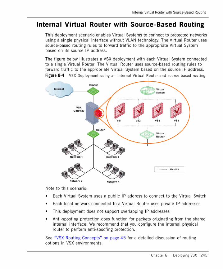
Internal Virtual Router with Source-Based Routing
Chapter 8 Deploying VSX 245
Internal Virtual Router with Source-Based RoutingThis deployment scenario enables Virtual Systems to connect to protected networks using a single physical interface without VLAN technology. The Virtual Router uses source-based routing rules to forward traffic to the appropriate Virtual System based on its source IP address.
The figure below illustrates a VSX deployment with each Virtual System connected to a single Virtual Router. The Virtual Router uses source-based routing rules to forward traffic to the appropriate Virtual System based on the source IP address. Figure 8-4 VSX Deployment using an internal Virtual Router and source-based routing
Note to this scenario:
• Each Virtual System uses a public IP address to connect to the Virtual Switch
• Each local network connected to a Virtual Router uses private IP addresses
• This deployment does not support overlapping IP addresses
• Anti-spoofing protection does function for packets originating from the shared internal interface. We recommend that you configure the internal physical router to perform anti-spoofing protection.
See “VSX Routing Concepts” on page 45 for a detailed discussion of routing options in VSX environments.
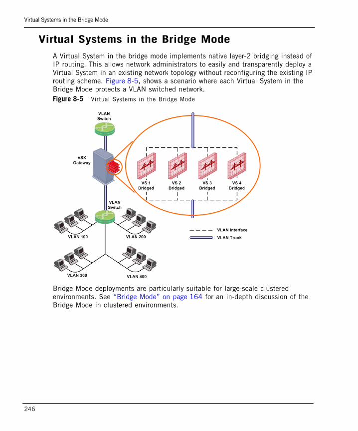
Virtual Systems in the Bridge Mode
246
Virtual Systems in the Bridge ModeA Virtual System in the bridge mode implements native layer-2 bridging instead of IP routing. This allows network administrators to easily and transparently deploy a Virtual System in an existing network topology without reconfiguring the existing IP routing scheme. Figure 8-5, shows a scenario where each Virtual System in the Bridge Mode protects a VLAN switched network.Figure 8-5 Virtual Systems in the Bridge Mode
Bridge Mode deployments are particularly suitable for large-scale clustered environments. See “Bridge Mode” on page 164 for an in-depth discussion of the Bridge Mode in clustered environments.

Cluster Deployments
Chapter 8 Deploying VSX 247
Cluster Deployments
In This Section
This section presents several examples of cluster deployments that highlight important VSX features. The discussion is intended to introduce these features as they relate to deployment strategy. For an in-depth, conceptual discussion of cluster deployments, refer to chapter 5, “Introduction to VSX Clusters” on page 147.
Active/Standby Bridge ModeThe Active/Standby Bridge Mode provides path redundancy and loop prevention, while offering seamless support for Virtual System Load Sharing and overcoming many Spanning Tree Protocol (STP) Bridge mode limitations.
The following sections describe two cluster deployment scenarios using the Active/Standby Bridge Mode.
Active/Standby Bridge Mode page 247
VSX Gateway High Availability page 250
Per Virtual System High Availability page 250
Virtual System Load Sharing (VSLS) page 251

Cluster Deployments
248
VLAN Shared Interface Deployment - Active Standby Bridge Mode
In this scenario, each individual member connects to pair of redundant switches via a VLAN trunk. All Virtual Systems in a given member share the same VLAN trunk. The following figure illustrates an example of such a deployment with active, standby and backup members.Figure 8-6 Active/Standby Bridge mode - VLAN Shared Interface Deployment
When using the Active/Standby Bridge mode in a high availability deployment, VSX directs traffic to members according to predefined priorities and member status. In VSLS deployments, VSX distributes the traffic load amongst members according to a set of predefined preferences.
This deployment scenario is appropriate for very large enterprises, as described in “Enterprise Deployments” on page 253.

Cluster Deployments
Chapter 8 Deploying VSX 249
Three Layer Hierarchical Deployment
A three layer hierarchical model is appropriate for large, high-traffic network environments. It contains a mixture of components as described below:
1. A core network, comprised of high-speed backbone switches directs traffic to and from the Internet and other external networks.
2. A distribution layer, comprised of routers, provides connectivity between the core and the access layer.
3. An access layer, comprised of redundant LAN switches, forwards traffic to and from internal networks.
VSX, using the Active/Standby Bridge mode, can be incorporated into the distribution layer, enforcing the security policy. This is illustrated in the following figure:Figure 8-7 Active/Standby Bridge mode - Three Layer Hierarchical Model
The routers direct external, “dirty” traffic (typically from the Internet) to the appropriate Virtual System via a segregated VLAN. Filtered, “clean” traffic exits the Virtual System via a separate segregated VLAN back to the routers and on to internal destinations.
This deployment scenario is appropriate for very large enterprises, as described in “Enterprise Deployments” on page 253.

Cluster Deployments
250
VSX Gateway High AvailabilityVSX gateway high availability ensures continuity of service by initiating failover of all virtual devices on the primary member to a designated standby member. Failover occurs if the member itself fails or any one of its virtual devices fails.Figure 8-8 VSX Gateway High Availability
In the above example, member M1 experiences a failure that affects VS1, causing all Virtual Systems to immediately fail over to member M2.
Per Virtual System High AvailabilityWith per Virtual System high availability, each Virtual System monitors its own interfaces for failure.Figure 8-9 Per Virtual System High Availability
In this example, each cluster member contains three identical, synchronized Virtual Systems. The member designated as M1 currently process traffic for all Virtual Systems. If VS2 fails on M1, it fails over to its peer in M2. VS1 and VS3 continue to function normally on M1.
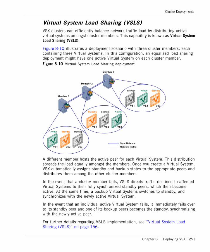
Cluster Deployments
Chapter 8 Deploying VSX 251
Virtual System Load Sharing (VSLS)VSX clusters can efficiently balance network traffic load by distributing active virtual systems amongst cluster members. This capability is known as Virtual System Load Sharing (VSLS).
Figure 8-10 illustrates a deployment scenario with three cluster members, each containing three Virtual Systems. In this configuration, an equalized load sharing deployment might have one active Virtual System on each cluster member. Figure 8-10 Virtual System Load Sharing deployment
A different member hosts the active peer for each Virtual System. This distribution spreads the load equally amongst the members. Once you create a Virtual System, VSX automatically assigns standby and backup states to the appropriate peers and distributes them among the other cluster members.
In the event that a cluster member fails, VSLS directs traffic destined to affected Virtual Systems to their fully synchronized standby peers, which then become active. At the same time, a backup Virtual Systems switches to standby, and synchronizes with the newly active Virtual System.
In the event that an individual active Virtual System fails, it immediately fails over to its standby peer and one of its backup peers becomes the standby, synchronizing with the newly active peer.
For further details regarding VSLS implementation, see “Virtual System Load Sharing (VSLS)” on page 156.

Organizational Deployment Strategies
252
Organizational Deployment StrategiesIn This Section
This section presents deployment scenarios for different types of large organizations and illustrates how VSX provides security both internally and at the perimeter. The discussion covers the following types of organizations:
• Large Enterprises
• Managed Service Providers
• Data Centers
Enterprise Deployments page 253
Managed Service Providers Using Provider-1 page 256
Data Centers page 258

Enterprise Deployments
Chapter 8 Deploying VSX 253
Enterprise DeploymentsLarge enterprise network environments typically contain a wide variety of diverse networks, distributed over multiple locations around the world. These networks often have differing security and access requirements for various departments and branches. The ability to centrally manage network security while maintaining throughput is a critical requirement.
Core Network SecurityMany Enterprise environments are based on core networks. Situated adjacent to core network backbone switches, VSX protects the internal network by providing security at layer-2, layer-3 or both. VSX communicates with the core network using the existing infrastructure. With Virtual Systems in the Bridge Mode, VSX can protect departmental networks, while simultaneously preventing network segmentation. In this case, switches are located at the entrance to each department’s network.Figure 8-11 Core network deployment
VSX ensures connectivity between the core network and the Internet or external networks, while providing perimeter security. Security can be configured on a per VLAN basis.
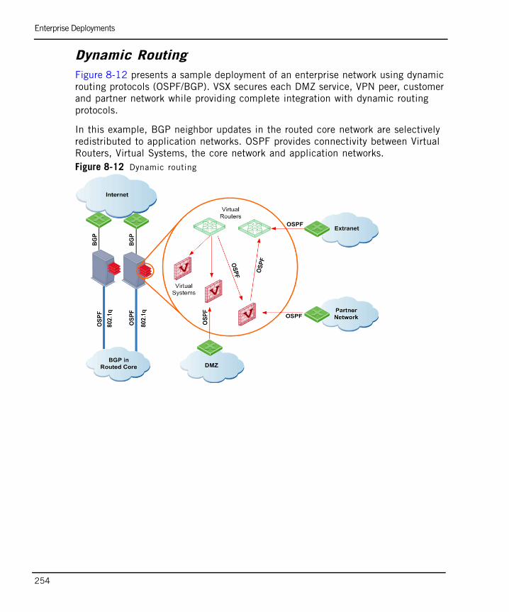
Enterprise Deployments
254
Dynamic RoutingFigure 8-12 presents a sample deployment of an enterprise network using dynamic routing protocols (OSPF/BGP). VSX secures each DMZ service, VPN peer, customer and partner network while providing complete integration with dynamic routing protocols.
In this example, BGP neighbor updates in the routed core network are selectively redistributed to application networks. OSPF provides connectivity between Virtual Routers, Virtual Systems, the core network and application networks. Figure 8-12 Dynamic routing

Enterprise Deployments
Chapter 8 Deploying VSX 255
Perimeter SecurityIn Figure 8-13, security is enforced on a per-VLAN basis. The OSPF and BGP Dynamic routing protocols provide connectivity to multiple security zones along the perimeter.Figure 8-13 Perimeter security in an enterprise deployment
Notes to this scenario:
• Partners access network resources remotely via Virtual Systems
• Each Virtual System has its own security policy based on its requirements
• Logs and audit information for each partner is collected separately, and saved to a private database
• Applications and services are segregated by private Virtual Systems
• Multiple Virtual Routers/Switches are used to control the access paths

Managed Service Providers Using Provider-1
256
Managed Service Providers Using Provider-1Managed service providers supply connectivity and security services for customer networks. Some of these customers require remote access capabilities. In this service oriented environment, VSX and Provider-1 provide central management while facilitating connectivity and security without affecting the existing IP topology.
In the example shown in Figure 8-14, a VSX cluster resides in a Point of Presence (POP) deployment for a service provider. VSX consolidates hardware for the service provider while ensuring privacy and secure connectivity solutions (VPN) for customers. Figure 8-14 Service Provider deployment using Provider-1

Managed Service Providers Using Provider-1
Chapter 8 Deploying VSX 257
Notes to this scenario:
• POP is monitored by the network operation center
• This scenario is appropriate for both high availability and Virtual System Load Sharing cluster modes
• VSX and Provider-1 provide a centralized, granular provisioning system, where each customer manages its own security without the ability to define Virtual Systems and other network components
• Customers have secure VPN connectivity
• Each customer’s forensic information is collected separately, and logged to a private database on a centralized Provider-1 Multi-domain Logging Module (MLM).
• Applications and services are segregated by discrete Virtual Systems. Access to these services and applications is based on need.
• Multiple Virtual Routers/Switches are used to control access paths.

Data Centers
258
Data CentersData center providers supply external hosting services for customer servers and databases. The service typically includes infrastructure, connectivity, and security for multiple customers. The example scenario presented in Figure 8-15 shows multiple customer networks sharing a common physical infrastructure and MPLS backbone that provide connectivity between each customer and the data center.
Customer A connects to its web hosting servers. Customer B connects to its mail servers, and Customer C connects to its database servers. To provide network security and management, the data center provider deploys a VSX gateway with one Virtual System for each customer.Figure 8-15 VSX protecting a data center
This scenario offers a cost effective scalability solution for network expansion by means of remote connectivity. In this example, a VPN connection between a customer Virtual System and a VPN-1 UTM Edge device protecting a remote network, integrates that network into the MPLS core. Similarly, a Virtual System can provide access for individual remote users who connect intermittently.

Data Centers
Chapter 8 Deploying VSX 259
Data Centers Within an EnterpriseThis example scenario illustrates how VSX provides security management for enterprise data centers. By assigning layer-2 connections to Virtual Systems, VSX reduces the number of physically managed devices within a data center while providing the same high level of security.
In Figure 8-16, a VSX gateway allows authorized users to access data center resources. The objective here is to protect shared resources with differing access permissions and security requirements, while implementing network granularity.Figure 8-16 Data centers within an enterprise
For example, one Virtual System protects databases against SQL vulnerabilities. Another Virtual System protects Web Servers using SmartDefense and/or Web Intelligence. When new applications and services are added to the enterprise data center, new Virtual Systems are easily created to secure them according to their specific requirements.

Data Centers
260

261
Chapter 9VSX Diagnostics and Troubleshooting
In This Chapter
Introduction page 262
General Troubleshooting Steps page 262
Per Virtual System Debugging page 264
Troubleshooting Specific Problems page 266
Introduction
262
IntroductionThis chapter presents basic diagnostic and troubleshooting procedures that should be followed in the event you encountering a problem while working with VSX. This diagnostic routine will assist you in determining the source of the problem. This chapter presents several known issues and their solutions.
Most problems are caused by configuration errors occurring during the process of defining VSX gateway, clusters and/or virtual devices. Another common source of problems involves networking and connectivity issues affecting VSX behavior. Theses problems are listed according to the order in which you will likely encounter them. Before reading and following a certain workaround, make sure you've read all the previous workarounds, and that those steps in the configuration were successful.
In some of the cases, one initial problem can cause problems in later stages of the configuration. For that reason, it is important to find the root of the problem when you are trying to understand what went wrong.
General Troubleshooting StepsIf you suspect that there is a problem with your VSX configuration, there are several diagnostic procedures that you can follow to determine the source. These procedures utilize various commands that are explained in “Command Line Reference” on page 273.
1. Perform a basic configuration check for each gateway or cluster member by running the fw vsx stat -v command. The output will allow you to:
a. Account for all Virtual Systems and verify that none are missing from the configuration.
b. Verify that all Virtual devices are active
c. Verify that the correct security policy is installed for each Virtual System
d. Verify the SIC trust has been established with the management server
2. Run the cplic print command on each VSX gateway, cluster member and management server to verify that you have the appropriate licenses installed.
3. Run the cphaprob stat command on each cluster member to verify its status. If a member is listed with a status other than Active, Standby, or Backup, refer to the “Troubleshooting” chapter in the ClusterXL Administration Guide for additional troubleshooting assistance.
General Troubleshooting Steps
Chapter 9 VSX Diagnostics and Troubleshooting 263
4. If you suspect that a Virtual System is experiencing connectivity problems, perform the following steps:
a. Run: vsx set to set the context to the appropriate Virtual System.
b. Run fw [-v vsname | vsid] getifs to display the interface list for the Virtual System.
c. Examine connectivity status using standard operating system commands and tools such as: ping, traceroute, tcpdump, ip route, ftp, etc. Some of these run according to context (i.e. routing, source and destination IP addresses). .
For SecurePlatform and Crossbeam platforms, execute the ip route and ip link commands.
If these tests indicate that all interfaces and routers have connectivity, and appear to be functioning correctly, you should monitor the passage of packets through the system.
5. Execute the fw monitor -v [vsname or vsid] commands to capture details of packets at multiple points. This may return multiple reports on the same packet as it passes various capture points. This command does not report on Virtual Routers, except for packets destined to an external Virtual Router.
6. Execute the tcpdump command to display transmitted or received packets for specific interfaces, including Warp interfaces. This often provides valuable clues for resolving connectivity issues.
Note - The Performance Pack may have an adverse effect on the capabilities of thefw monitor command.

Per Virtual System Debugging
264
Per Virtual System DebuggingYou can now filter debug message by the Virtual System responsible for generating them. By default, debug generates messages for all Virtual Systems.
Filtering Debug MessagesTo display only those debug messages generated by one or more specific Virtual Systems or other virtual devices, append the -v argument to the fw ctl debug command followed by the VSID (Virtual System ID) of those Virtual Systems that you wish to view.
To display messages for a specific Virtual System, execute the command fw ctl debug -v <vsid>, on the VSX gateway or member where <vsid> is the ID of the Virtual System that you wish to examine.
You can combine the -v argument with other setting flags.
For example, the fw ctl debug -v 1,2,3 command displays only those messages generated by Virtual Systems 1, 2 and 3.
Determining Which Virtual System Generated Debug Messages
The VSID appears between the <> characters preceding each debug message. No data appears between the <> characters for those messages not associated with a Virtual System. To display debug messages with the VSID, run the fw ctl kdebug -p vsid command.
Limitations• The current version only supports debug messages generated by the fw kernel.
• Some messages may be preceded by empty <> characters even though a specific Virtual System generated the message. This limitation is especially noticeable when running load and issue debugs.
• When running the fwkdebug_limit_retrieve command with VSID 0, the incorrect VSID may appear between the <> characters in certain rare instances.
Limitations
Chapter 9 VSX Diagnostics and Troubleshooting 265
- To ensure that the displayed VSID is accurate, run the following command:fw ctl set int fwkdebug_limit_retrieve_vsid 1. You may receive more empty <> characters, but those containing VSIDs will be accurate.
Troubleshooting Specific Problems
266
Troubleshooting Specific ProblemsIn This Section
Cannot Establish SIC Trust for Gateway or Cluster page 267
SIC Trust Problems with new Virtual Devices page 268
Re-establishing SIC Trust with Virtual Devices page 268
Sync networks don’t match page 269
Install Policy Error Using VSX Creation Wizard page 270
Internal Host Cannot Ping Virtual System page 271
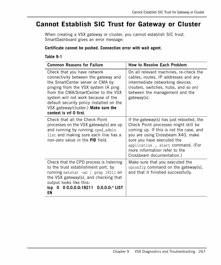
Cannot Establish SIC Trust for Gateway or Cluster
Chapter 9 VSX Diagnostics and Troubleshooting 267
Cannot Establish SIC Trust for Gateway or ClusterWhen creating a VSX gateway or cluster, you cannot establish SIC trust. SmartDashboard gives an error message:
Certificate cannot be pushed. Connection error with wait agent.
Table 9-1
Common Reasons for Failure How to Resolve Each Problem
Check that you have network connectivity between the gateway and the SmartCenter server or CMA by pinging from the VSX system (A ping from the CMA/SmartCenter to the VSX system will not work because of the default security policy installed on the VSX gateway/cluster.) Make sure the context is vrf 0 first.
On all relevant machines, re-check the cables, routes, IP addresses and any intermediate networking devices (routers, switches, hubs, and so on) between the management and the gateway(s).
Check that all the Check Point processes on the VSX gateway(s) are up and running by running cpwd_admin list and making sure each line has a non-zero value in the PID field.
If the gateway(s) has just rebooted, the Check Point processes might still be coming up. If this is not the case, and you are using Crossbeam X40, make sure you have executed the application … start command. (For more information refer to the Crossbeam documentation.)
Check that the CPD process is listening to the trust establishment port, by running netstat -an | grep 18211 on the VSX gateway(s), and checking that output looks like this:tcp 0 0 0.0.0.0:18211 0.0.0.0:* LISTEN
Make sure that you executed the cpconfig command on the gateway(s), and that it finished successfully.

SIC Trust Problems with new Virtual Devices
268
SIC Trust Problems with new Virtual DevicesWhen creating a new Virtual System, Virtual Router or Virtual Switch, you cannot establish SIC trust.
Re-establishing SIC Trust with Virtual DevicesIn the event that you encounter connectivity problems due to the loss of SIC trust for a specific virtual device, you can use the following procedure to manually re-establish trust:
1. Execute the following command from the VSX Gateway command line (In the expert mode): vsx sic reset <vsid>.
vsid: Identification number of the virtual device
2. Execute the following command(s) on the management server:
a. # mdsenv <target_cma_name> (Provider-1 only)
b. # cpca_client revoke_cert -n <vs_sic_name>
vs_sic_name: Virtual device SIC name. To determine the SIC name, run guidbedit.exe and search for the sic_name attribute on the virtual device network object.
3. In SmartDashboard, open the virtual device object and click OK. This action creates a new SIC certificate for the virtual device and saves it on the VSX gateway.
Table 9-2
Common Reasons for Failure How to Resolve Each Problem
Time or time zone mismatch between the management and the gateway. For proper SIC operation, the time, date and time zone must be synchronized between the management server and gateways/ cluster members.
Execute the /bin/date -u command on all machines, to obtain the correct UTC/GMT time. The machines can be in different time zones, as long as their UTC/GMT times match.
Change the time, date and time zone on the management and/or the gateway(s) so that their UTC/GMT times match. Refer to you operating system documentation for the exact commands needed to accomplish this.
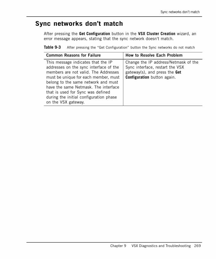
Sync networks don’t match
Chapter 9 VSX Diagnostics and Troubleshooting 269
Sync networks don’t matchAfter pressing the Get Configuration button in the VSX Cluster Creation wizard, an error message appears, stating that the sync network doesn't match.
Table 9-3 After pressing the “Get Configuration” button the Sync networks do not match
Common Reasons for Failure How to Resolve Each Problem
This message indicates that the IP addresses on the sync interface of the members are not valid. The Addresses must be unique for each member, must belong to the same network and must have the same Netmask. The interface that is used for Sync was defined during the initial configuration phase on the VSX gateway.
Change the IP address/Netmask of the Sync interface, restart the VSX gateway(s), and press the Get Configuration button again.
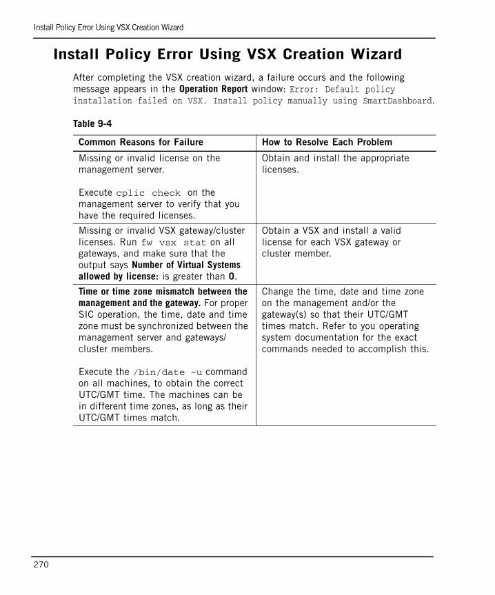
Install Policy Error Using VSX Creation Wizard
270
Install Policy Error Using VSX Creation WizardAfter completing the VSX creation wizard, a failure occurs and the following message appears in the Operation Report window: Error: Default policy installation failed on VSX. Install policy manually using SmartDashboard.
Table 9-4
Common Reasons for Failure How to Resolve Each Problem
Missing or invalid license on the management server.
Execute cplic check on the management server to verify that you have the required licenses.
Obtain and install the appropriate licenses.
Missing or invalid VSX gateway/cluster licenses. Run fw vsx stat on all gateways, and make sure that the output says Number of Virtual Systems allowed by license: is greater than 0.
Obtain a VSX and install a valid license for each VSX gateway or cluster member.
Time or time zone mismatch between the management and the gateway. For proper SIC operation, the time, date and time zone must be synchronized between the management server and gateways/ cluster members.
Execute the /bin/date -u command on all machines, to obtain the correct UTC/GMT time. The machines can be in different time zones, as long as their UTC/GMT times match.
Change the time, date and time zone on the management and/or the gateway(s) so that their UTC/GMT times match. Refer to you operating system documentation for the exact commands needed to accomplish this.

Internal Host Cannot Ping Virtual System
Chapter 9 VSX Diagnostics and Troubleshooting 271
Internal Host Cannot Ping Virtual System After defining a Virtual System with an internal VLAN interface, an internal host on that VLAN cannot ping the Virtual System internal or external IP address.
Table 9-5
Common Reasons for Failure How to Resolve Each Problem
A policy allowing the communication was not installed on the Virtual System. Note that after creating a Virtual System, it has a default policy that blocks all traffic.
Install a policy on the Virtual System that enables the traffic. Check with the SmartView Tracker that the Virtual System is allowing the traffic.
There is the VLAN configuration problem on a switch, or physical cable problem.
Check the switch configuration. Make sure that VLAN tag configured on the switch is the same as used for the Virtual System VLAN interface.
Check the cables, and make sure that you have plugged the cable from the switch to the correct port on the VSX gateway or cluster members.
Incorrect routing on adjacent routers or hosts.
Check the routing tables on intermediate routers and hosts. You can use tcpdump on the relevant VLAN interface on the VSX gateway or cluster member to verify that the traffic is arriving to and leaving the VSX machine.
Incorrect IP address or net mask defined on the Virtual System VLAN interface.
Check the IP address and the net mask assigned to the Virtual System internal VLAN interface.
Internal Host Cannot Ping Virtual System
272

273
Chapter 10Command Line Reference
In This Chapter
Firewall (fw) Commands page 274
VSX Commands page 278
VSX Resource Control Commands page 284
The vsx_util Commands page 289
The cphaprob Command page 298

Firewall (fw) Commands
274
Firewall (fw) CommandsThis section presents the usage of standard firewall (fw) commands as applicable to VSX gateways and Virtual Systems.
In This Section
fw getifs page 275
fw monitor page 276
fw tab page 277

Firewall (fw) Commands
Chapter 10 Command Line Reference 275
fw getifsDescription Gets firewall driver interface list for designated Virtual System. The
default gives the VSX gateway.
Usage fw [-vs vsid | vsname] getifs
Syntax
Return Value 0 (zero) indicates successfully executed, any other response indicates failure.
Example The fw getifs command shows all interfaces to which the Firewall is attached, their IP address, and network mask.
Output
Argument Description
[-vs vsid | vsname] Gets Firewall driver interface list for a specific
Virtual System.
You can specify a Virtual System by name or by ID. If you omit the -vs argument, the command returns only those interfaces associated with the current context.The default gives the VSX gateway.
fw getifslocalhost vnd0 0.0.0.0 0.0.0.0localhost eth0 4.4.6.101 255.255.0.0localhost eth1 0.0.0.0 0.0.0.0localhost sdp0 0.0.0.0 0.0.0.0localhost int 0.0.0.0 0.0.0.0localhost mgmt 10.18.83.171 255.255.255.0localhost sync 7.7.7.171 255.255.255.0localhost wrpj50001 0.0.0.0 0.0.0.0localhost wrpj50003 0.0.0.0 0.0.0.0
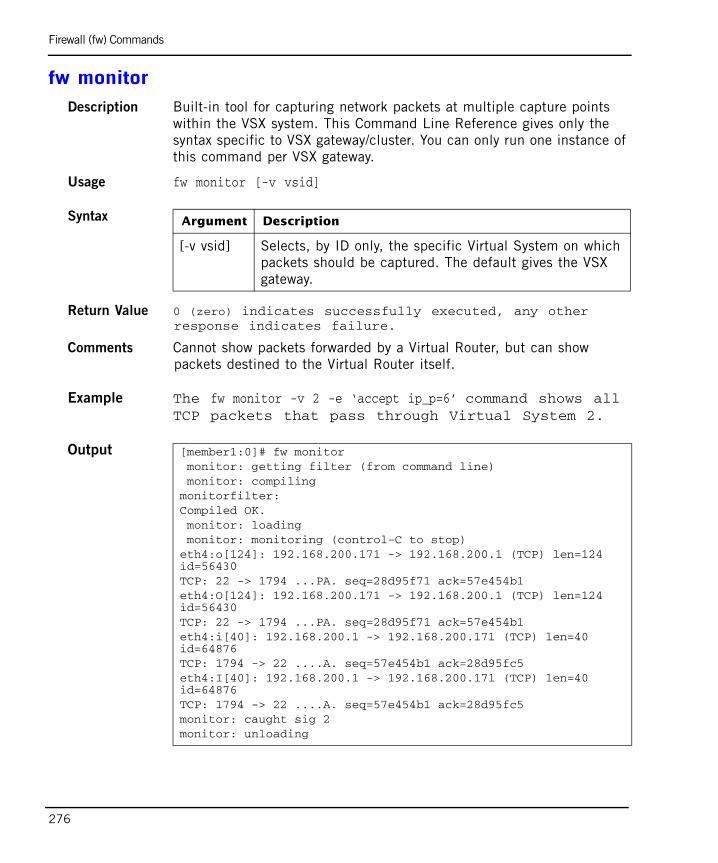
Firewall (fw) Commands
276
fw monitor Description Built-in tool for capturing network packets at multiple capture points
within the VSX system. This Command Line Reference gives only the syntax specific to VSX gateway/cluster. You can only run one instance of this command per VSX gateway.
Usage fw monitor [-v vsid]
Syntax
Return Value 0 (zero) indicates successfully executed, any other response indicates failure.
Comments Cannot show packets forwarded by a Virtual Router, but can show packets destined to the Virtual Router itself.
Example The fw monitor -v 2 -e ‘accept ip_p=6’ command shows all TCP packets that pass through Virtual System 2.
Output
Argument Description
[-v vsid] Selects, by ID only, the specific Virtual System on which packets should be captured. The default gives the VSX gateway.
[member1:0]# fw monitor monitor: getting filter (from command line) monitor: compilingmonitorfilter:Compiled OK. monitor: loading monitor: monitoring (control-C to stop)eth4:o[124]: 192.168.200.171 -> 192.168.200.1 (TCP) len=124 id=56430TCP: 22 -> 1794 ...PA. seq=28d95f71 ack=57e454b1eth4:O[124]: 192.168.200.171 -> 192.168.200.1 (TCP) len=124 id=56430TCP: 22 -> 1794 ...PA. seq=28d95f71 ack=57e454b1eth4:i[40]: 192.168.200.1 -> 192.168.200.171 (TCP) len=40 id=64876TCP: 1794 -> 22 ....A. seq=57e454b1 ack=28d95fc5eth4:I[40]: 192.168.200.1 -> 192.168.200.171 (TCP) len=40 id=64876TCP: 1794 -> 22 ....A. seq=57e454b1 ack=28d95fc5monitor: caught sig 2monitor: unloading

Firewall (fw) Commands
Chapter 10 Command Line Reference 277
fw tabDescription Shows state tables for a specific Virtual System. State tables are used to
keep state information which the Virtual System needs in order to correctly inspect packets.
Usage fw [-vs vsid | vsname] tab [-t table name] [...]
Syntax
Example fw -vs 1 tab -t connections
Output
Argument Description
[-vs vsid | vsname] Shows state tables for a specific Virtual
System.
Using this option you can specify a Virtual System by name or by ID.The default gives the VSX gateway.
-t table name Shows table for the specified Virtual System.
[...] Arguments as defined for non-VSX machines.
fw -vs 1 tab -t connectionslocalhost:-------- connections --------dynamic, id 8158, attributes: keep, sync, expires 25, refresh, limit 15000, hashsize 32768, kbuf 16 17 18 19 20 21 22 23 24 25 26 27 28 29 30, free function 90adc508 000000000, 0a125364, 00008a69, 0a12ae0a, 00004710, 00000006; 0001c001, 00804000, 08000000, 00000e10, 00000000, 3f7c2df6, 00000001, 66010202, 000007b6, ffffffff, ffffffff, ffffffff, ffffffff, 00000000, 00000000, 00000000, 00000000, 00000000, 3bcd7000, 00000000, 00000000, 00000000; 3596/3600>00000001, 0a12ae0a, 00004710, 0a125364, 00008a69, 00000006> -> 00000000, 0a125364, 00008a69, 0a12ae0a, 00004710, 00000006> (00000005)00000000, 0a125364, 00008a6c, 0a12ab0a, 00004710, 00000006; 0001c001, 00804000, 08000000, 00000e10, 00000000, 3f7c2e4b, 00000001, 65060404, 000007b6, 0000000b, 0000000b, ffffffff, ffffffff, 00000000, 00000000, 00000000, 00000000, 00000000, 1fce4000, 00000000, 00000000, 00000000, 00000000, 00000000; 3581/3600>00000001, 0a12ac0a, 00004710, 0a125364, 00008a6b, 00000006> -> 00000000, 0a125364, 00008a6b, 0a12ac0a, 00004710, 00000006> (00000005)600>
VSX Commands
278
VSX CommandsThis section describes a selection of the VSX commands.
In This Section
vsx fetch page 279
vsx fetchvs page 280
vsx get page 281
vsx set page 281
vsx stat page 282
vsx start_dr page 283
vsx sic reset page 283

VSX Commands
Chapter 10 Command Line Reference 279
vsx fetch Description Fetches and executes configuration files.
Usage vsx fetch [-v | -q| -s] [-f conf_file] [local]vsx fetch [-v | -q] -C “command”vsx fetch [-v | -q| -c| -n| -s] [management] [local]
Syntax
Return Value 0 (zero) indicates successfully executed, any other response indicates failure.
Example The fw vsx fetch command fetches the most current configuration files from the Main CMA, and applies it to the VSX gateway.
Argument Description
-c Cluster mode.
-n Does not run local.vsall if VSX configuration, fetched from management, is up-to-date.
-s Concurrent fetches for multi-processor environment.
-q Quiet output. Nothing is displayed except the summary lines at the time of command startup and finish.
-v Gives verbose (detailed) information.
-f conf_file Fetches NCS commands configuration file instead of the default local.vsall.
local Reads local.vsall configuration file from $FWDIR/state/local/vsx and executes the NCS script.
management Fetches local.vsall from management, replace and run it.
-C “command” Runs specific selected NCS command.

VSX Commands
280
Output
vsx fetchvs Description Retrieves a specific Virtual System configuration file based on the
information stored locally on the gateway.
Usage fw vsx fetchvs [-v | -q] [VS name | vsid]
Syntax
Comments 0 (zero) indicates successfully executed, any other response indicates failure.
Example The fw vsx fetchvs California command recreates Virtual System - California
Output
fw vsx fetch
Fetching VSX Configuration From: 10.18.99.101
Local VSX Configuration is Up-To-Date. Cleaning un-used Virtual Systems entries (local.vskeep).
Purge operation succeeded. Fetching Virtual Systems configuration file (local.vsall).
SecureXL device has been enabled for vsid 1SecureXL device has been enabled for vsid 2SecureXL device has been enabled for vsid 3 Virtual Systems configuration file installed successfully
Argument Description
-q Quiet output. Nothing is displayed except the summary lines at the time of command startup and finish.
-v Gives verbose (detailed) information.
VS name|vsid Selects specific Virtual System by name or by ID.
fw vsx fetchvs 2SecureXL device has been enabled for vsid 2
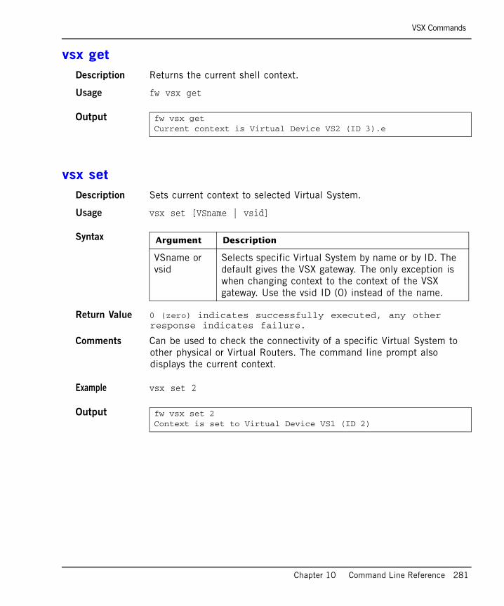
VSX Commands
Chapter 10 Command Line Reference 281
vsx getDescription Returns the current shell context.
Usage fw vsx get
Output
vsx setDescription Sets current context to selected Virtual System.
Usage vsx set [VSname | vsid]
Syntax
Return Value 0 (zero) indicates successfully executed, any other response indicates failure.
Comments Can be used to check the connectivity of a specific Virtual System to other physical or Virtual Routers. The command line prompt also displays the current context.
Example vsx set 2
Output
fw vsx get Current context is Virtual Device VS2 (ID 3).e
Argument Description
VSname or vsid
Selects specific Virtual System by name or by ID. The default gives the VSX gateway. The only exception is when changing context to the context of the VSX gateway. Use the vsid ID (0) instead of the name.
fw vsx set 2Context is set to Virtual Device VS1 (ID 2)

VSX Commands
282
vsx statDescription Displays VSX status information.
Usage fw vsx stat [-v] [-l]
Syntax
Output
Argument Description
-v Gives verbose (detailed) information - shows the status table in full.
-l Gives a detailed list of all the virtual devices.
VSX Gateway Status==================Name: MyGatewaySecurity Policy: MyGateway_VSXInstalled at: 10Dec2007 10:31:25SIC Status: Trust
Number of Virtual Systems allowed by license: 100Virtual Systems [active / configured]: 2/2 Virtual Routers and Switches [active / configured]: 1/1 Total connections [current/limit} 4/46000
Virtual Devices Status======================
ID | Type & Name | Security Policy | Installed at | SIC Stat-----+-------------+-----------------+----------------+-------- 1 | W VSW_1 |<Not Applicable> | | Trust 2 | S VS1 |Standard | 10Apr2005 10:31| Trust
3 | S VSs2 |Standard | 10Apr2005 10:31| Trust
Type: S - Virtual System, B - Virtual System in Bridge mode, R - Virtual Router, W - Virtual Switch, ? - Information unavailable.
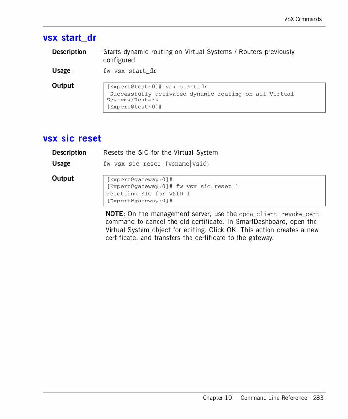
VSX Commands
Chapter 10 Command Line Reference 283
vsx start_drDescription Starts dynamic routing on Virtual Systems / Routers previously
configured
Usage fw vsx start_dr
Output
vsx sic resetDescription Resets the SIC for the Virtual System
Usage fw vsx sic reset {vsname|vsid}
Output
NOTE: On the management server, use the cpca_client revoke_cert command to cancel the old certificate. In SmartDashboard, open the Virtual System object for editing. Click OK. This action creates a new certificate, and transfers the certificate to the gateway.
[Expert@test:0]# vsx start_dr Successfully activated dynamic routing on all Virtual Systems/Routers[Expert@test:0]#
[Expert@gateway:0]#[Expert@gateway:0]# fw vsx sic reset 1resetting SIC for VSID 1[Expert@gateway:0]#
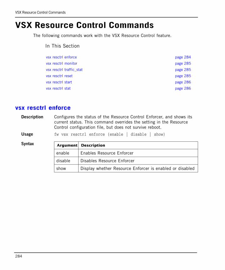
VSX Resource Control Commands
284
VSX Resource Control CommandsThe following commands work with the VSX Resource Control feature.
In This Section
vsx resctrl enforceDescription Configures the status of the Resource Control Enforcer, and shows its
current status. This command overrides the setting in the Resource Control configuration file, but does not survive reboot.
Usage fw vsx resctrl enforce {enable | disable | show}
Syntax
vsx resctrl enforce page 284
vsx resctrl monitor page 285
vsx resctrl traffic_stat page 285
vsx resctrl reset page 285
vsx resctrl start page 286
vsx resctrl stat page 286
Argument Description
enable Enables Resource Enforcer
disable Disables Resource Enforcer
show Display whether Resource Enforcer is enabled or disabled

VSX Resource Control Commands
Chapter 10 Command Line Reference 285
vsx resctrl monitorDescription Configures the status of the Resource Control Monitor, and shows its
current status. This command overrides the setting in the Resource Control configuration file, but does not survive reboot.
Usage fw vsx resctrl monitor {enable | disable | show]
Syntax
vsx resctrl traffic_statDescription Displays the number of received and dropped packets for a Virtual
System. The counter can be reset via the command “vsx resctrl reset”.
Usage fw vsx resctrl -w {vsid} traffic_stat
Syntax
Output
vsx resctrl resetDescription Resets the monitoring statistics of Resource Control.
Usage fw vsx resctrl reset
Argument Description
enable Enables Resource Monitor
disable Disables Resource Monitor
show Display whether Resource Monitor is enabled or disabled
Argument Description
-w {vsid} Displays the statistics for the Virtual System specified in {vsid}. The default vsid is 0.
[Expert@rescon:0]# vsx resctrl -w 0 traffic_stat Packets processed by virtual system 0: 8582 Packets dropped by virtual system 0: 0
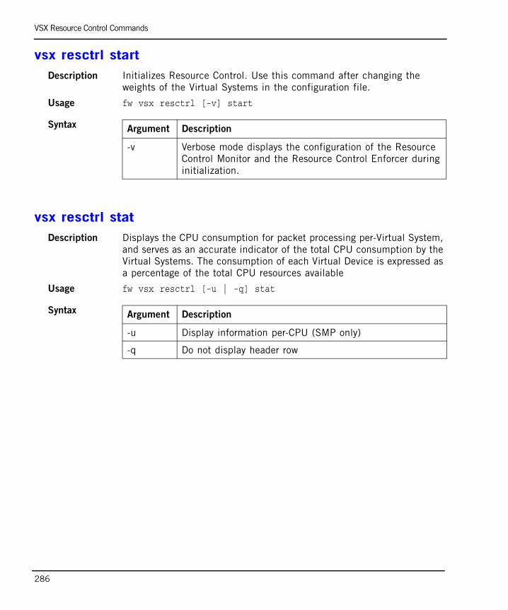
VSX Resource Control Commands
286
vsx resctrl startDescription Initializes Resource Control. Use this command after changing the
weights of the Virtual Systems in the configuration file.
Usage fw vsx resctrl [-v] start
Syntax
vsx resctrl statDescription Displays the CPU consumption for packet processing per-Virtual System,
and serves as an accurate indicator of the total CPU consumption by the Virtual Systems. The consumption of each Virtual Device is expressed as a percentage of the total CPU resources available
Usage fw vsx resctrl [-u | -q] stat
Syntax
Argument Description
-v Verbose mode displays the configuration of the Resource Control Monitor and the Resource Control Enforcer during initialization.
Argument Description
-u Display information per-CPU (SMP only)
-q Do not display header row

VSX Resource Control Commands
Chapter 10 Command Line Reference 287
Output
Notes
- For systems with more than one CPU, the time displayed is an average among all CPUs. To see the usage for each Virtual System per CPU, run the command vsx resctrl -u stat
- The VSX gateway itself, Virtual Switches and Virtual Routers are not assigned weights because they always receive the highest priority
- Total VS CPU Usage represents the total CPU utilization for all virtual devices, including Virtual Routers, Virtual Switches and the VSX gateway
- System CPU Usage reports the total CPU utilization for the entire machine
Without Argumentsfw vsx resctrl stat
Virtual Systems CPU Usage Statistics====================================
Number of CPUs/Hyper-threading: 4Monitoring active time: 14s
ID Name |Weight| 1sec 10sec 1min 1hr 24hr*========================+======+================================== 0 VSX2 | N/A | 0.11 0.06 0.08 0.07 0.01 1 VSX2_vs1 | 10 | 15.80 21.57 21.75 22.28 1.94 2 VSX2_vsw | N/A | 0.00 0.00 0.00 0.00 0.00 3 VSX2_vs2 | 10 | 16.91 22.57 22.77 23.09 2.01========================+======+==================================Total VS CPU Usage | 32.82 44.20 44.60 45.44 3.96===============================+==================================System CPU Usage | 99 99 99 99 89
Notes: - Monitoring has been active for less than 24 hours. Statistics are calculated only for monitoring active time. - The displayed statistics are the average usage on all CPUs.
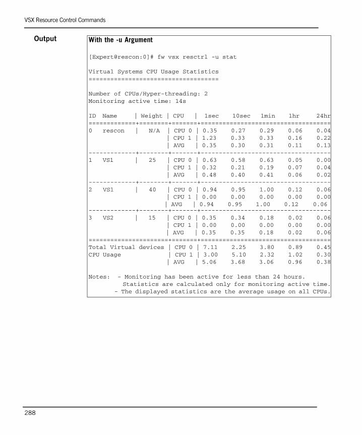
VSX Resource Control Commands
288
Output With the -u Argument
[Expert@rescon:0]# fw vsx resctrl -u stat
Virtual Systems CPU Usage Statistics====================================
Number of CPUs/Hyper-threading: 2Monitoring active time: 14s
ID Name | Weight | CPU | 1sec 10sec 1min 1hr 24hr=============+========+=======+====================================0 rescon | N/A | CPU 0 | 0.35 0.27 0.29 0.06 0.04 | CPU 1 | 1.23 0.33 0.33 0.16 0.22 | AVG | 0.35 0.30 0.31 0.11 0.13-------------+--------+-------+------------------------------------1 VS1 | 25 | CPU 0 | 0.63 0.58 0.63 0.05 0.00 | CPU 1 | 0.32 0.21 0.19 0.07 0.04 | AVG | 0.48 0.40 0.41 0.06 0.02-------------+--------+-------+------------------------------------2 VS1 | 40 | CPU 0 | 0.94 0.95 1.00 0.12 0.06 | CPU 1 | 0.00 0.00 0.00 0.00 0.00 | AVG | 0.94 0.95 1.00 0.12 0.06 -------------+--------+-------+------------------------------------3 VS2 | 15 | CPU 0 | 0.35 0.34 0.18 0.02 0.06 | CPU 1 | 0.00 0.00 0.00 0.00 0.00 | AVG | 0.35 0.35 0.18 0.02 0.06======================+=======+====================================Total Virtual devices | CPU 0 | 7.11 2.25 3.80 0.89 0.45CPU Usage | CPU 1 | 3.00 5.10 2.32 1.02 0.30 | AVG | 5.06 3.68 3.06 0.96 0.38
Notes: - Monitoring has been active for less than 24 hours. Statistics are calculated only for monitoring active time. - The displayed statistics are the average usage on all CPUs.

The vsx_util Commands
Chapter 10 Command Line Reference 289
The vsx_util Commandsvsx_util
Description The vsx_util command is a command line tool for performing various VSX maintenance tasks. You execute this command from the expert mode on the management server (SmartCenter server or a Main CMA in a Provider-1 environment).
Usage vsx_util [sub-command]
Syntax The following table summarizes the various vsx_util sub-commands and their usage:
Note - You must close SmartDashboard and/or the Provider-1 MDG before executing the vsx_util command. Failure to do so may result in a database locked error.
Argument Description
activate_plugin Activates the VSX plug-in for all CMAs containing virtual devices for a particular VSX gateway or cluster.
add_member Adds a new member to an existing cluster.
add_member_reconf Restores VSX configuration after adding a cluster member
change_mgmt_ip Change gateway or member management IP address
change_mgmt_private_net Change cluster internal communication network IP address
change_mgmt_subnet Change gateway or member management subnet
convert_cluster Switches cluster type between high availability and VSLS
reconfigure Restores VSX configuration on a new or freshly installed gateway or cluster member

The vsx_util Commands
290
Comments The vsx_util commands typically require you to enter the following information before executing the command:
• Management server name or IP address• User name and password• Object name: The command may ask for the name of one or more
VSX objects upon which the command operates • Most vsx_util sub-commands are interactive and require additional
user input. Brief descriptions of additional input requirements appear in the Input section for the various sub-commands. The instructions on the screen typically provide helpful information regarding required information.
activate_pluginDescription Activates the VSX plug-in for all customers managing virtual devices
in a Provider-1 deployment. This command eliminates the necessity of activating the VSX plug-in individually for each customer in a deployment containing many customers.
Usage vsx_util activate_plugin
Further Info. Getting Started Guide
redistribute_vsls Distributes Virtual Systems amongst members in a VSLS cluster
remove_member Remove cluster member
upgrade Upgrade VSX gateway or cluster member database to newer versions
view_vs_conf View Virtual Device configuration/status
vsls Display VSLS load sharing configuration and status
Argument Description
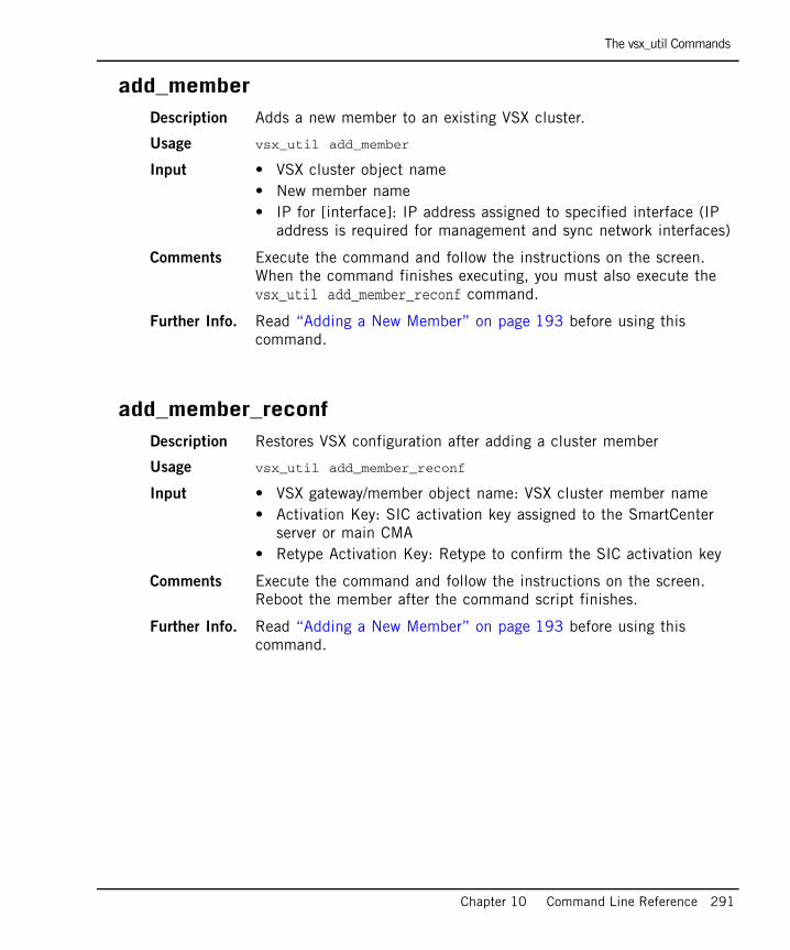
The vsx_util Commands
Chapter 10 Command Line Reference 291
add_memberDescription Adds a new member to an existing VSX cluster.
Usage vsx_util add_member
Input • VSX cluster object name• New member name• IP for [interface]: IP address assigned to specified interface (IP
address is required for management and sync network interfaces)
Comments Execute the command and follow the instructions on the screen. When the command finishes executing, you must also execute the vsx_util add_member_reconf command.
Further Info. Read “Adding a New Member” on page 193 before using this command.
add_member_reconfDescription Restores VSX configuration after adding a cluster member
Usage vsx_util add_member_reconf
Input • VSX gateway/member object name: VSX cluster member name• Activation Key: SIC activation key assigned to the SmartCenter
server or main CMA• Retype Activation Key: Retype to confirm the SIC activation key
Comments Execute the command and follow the instructions on the screen. Reboot the member after the command script finishes.
Further Info. Read “Adding a New Member” on page 193 before using this command.

The vsx_util Commands
292
change_mgmt_ipDescription Changes gateway or cluster member management IP address
Usage vsx_util change_mgmt_ip
Input • VSX gateway/member object name• New management IP address
Comments • We recommend that you back up the management database before using this command
• Execute the command and follow the instructions on the screen
change_mgmt_private_netDescription Changes the cluster internal communication network IP address
Usage vsx_util change_private_net
Input • VSX cluster object name• New cluster private network: New IP address for the cluster private
network
Comments • We recommend that you back up the management database before using this command.
• The private network IP address must be unique and not used anywhere behind the VSX gateway, cluster or Virtual Systems
• The new cluster private network must conform to the net mask 255.255.252.0
• Execute the command and follow the instructions on the screen
Further Info. “Internal Communication Network” on page 153

The vsx_util Commands
Chapter 10 Command Line Reference 293
change_mgmt_subnetDescription Change the gateway or member management subnet
Usage vsx_util change_mgmt_subnet
Input • VSX gateway/member object name• New subnet mask
Comments • Backup the management database before using this command• Only automatically generated routes are changed by the command
script. You must remove and/or change all manually created routes using the previous management subnet.
• To perform this action, execute the command and follow the instructions on the screen. Reboot the computer once the command script finishes.
convert_clusterDescription Converts the cluster type from high availability to VSLS or from VSLS
to high availability
Usage vsx_util convert_cluster
Input • VSX cluster object name• Desired ClusterXL mode: Enter HA for high availability or LS for
VSLS
Comments • Backup the management database before using this command.• To perform this action, execute the command and follow the
instructions on the screen.• When switching to high availability, all Virtual Systems are active
on the same member by default. Peer Virtual Systems are standby on other members.
• When converting to VSLS, all members must be in the Per Virtual System state.
• When switching to VSLS, active, standby and backup Virtual Systems are distributed amongst the members in order to balance the traffic load efficiently.
Further Info. See “Changing the Cluster Type” on page 199 for details.

The vsx_util Commands
294
reconfigureDescription Deploys or restores a VSX configuration to a newly installed gateway
or cluster member
Usage vsx_util reconfigure
Input • VSX gateway/member object name: Enter VSX cluster member name
• Activation Key: SIC activation key assigned to the SmartCenter server or CMA
• Retype Activation Key: Retype to confirm the SIC activation key
Comments • This command is also useful for restoring a gateway or member after a system failure.
• Execute the command and follow the instructions on the screen.• A new gateway or member must have the same hardware
specifications and configuration as its replacement and other cluster members. Most importantly, it must have the same number of interfaces (or more) and the same management IP address.
• The new or replacement machine must be a new installation. You cannot use a machine with a previous VSX configuration.
Further Info. See “Adding a New Member” on page 193 for further details.
redistribute_vslsDescription Distributes Virtual Systems amongst members in a VSLS cluster
Usage vsx_util redistribute_vsls
Input • VSX cluster object name• Redistribution option: Enter 1,2 or 3 representing the following
options:1 = Each cluster member is equally loaded with Virtual Systems2 = Set all Virtual Systems as active on the same cluster member3 = Manually assigned priority and weight for each Virtual System
Further Info. See “Distributing Virtual Systems Amongst Members” on page 206 for detailed instructions and procedures for using this command.

The vsx_util Commands
Chapter 10 Command Line Reference 295
remove_memberDescription Remove a member from an existing cluster
Usage vsx_util remove_member
Input • VSX cluster object name• Member name: Name of member to be removed
Comments • Backup the management database before using this command• Make certain that you remove member license before executing
this command• Execute the command and follow the instructions on the screen
Further Info. “Deleting a Member” on page 195
upgradeDescription Upgrade gateways and/or cluster members to newer versions
Usage vsx_util upgrade
Comments • This command updates all VSX objects in the management database to the designated newer version
• Execute the command and follow the instructions on the screen • After the command script finishes, execute the
vsx_util reconfigure command
view_vs_confDescription View virtual device configuration and status, including
troubleshooting information. This command also compares the management server database with the actual VSX gateways and cluster member configurations.
Usage vsx_util view_vs_conf
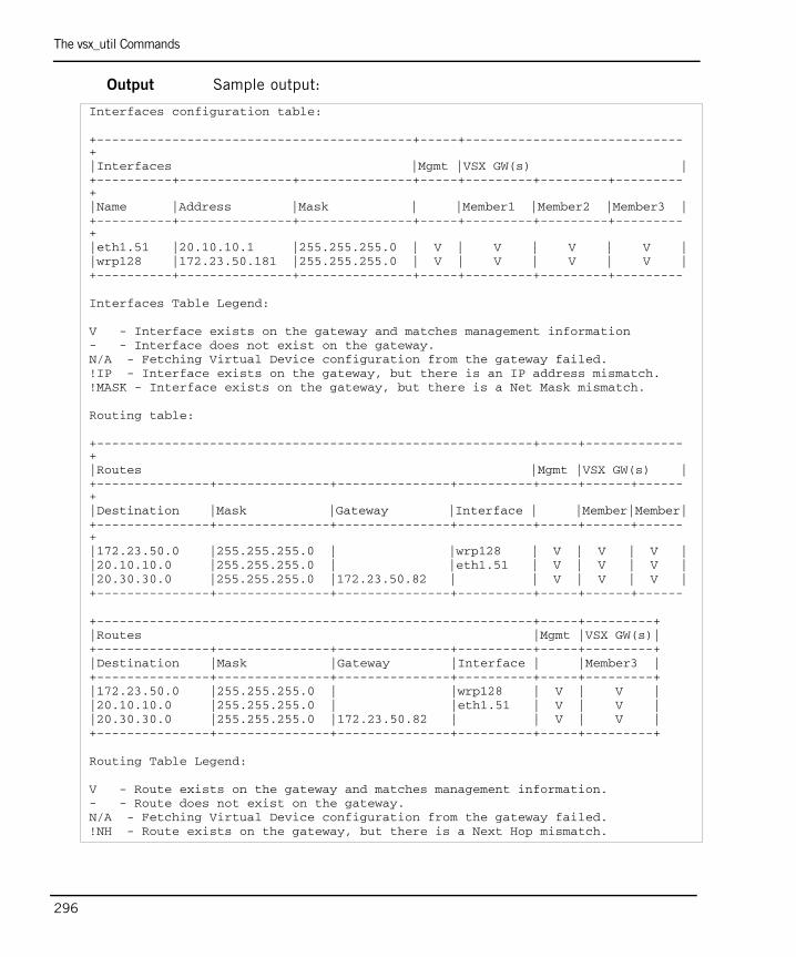
The vsx_util Commands
296
Output Sample output:
Interfaces configuration table:
+------------------------------------------+-----+-----------------------------+|Interfaces |Mgmt |VSX GW(s) |+----------+---------------+---------------+-----+---------+---------+---------+|Name |Address |Mask | |Member1 |Member2 |Member3 |+----------+---------------+---------------+-----+---------+---------+---------+|eth1.51 |20.10.10.1 |255.255.255.0 | V | V | V | V ||wrp128 |172.23.50.181 |255.255.255.0 | V | V | V | V |+----------+---------------+---------------+-----+---------+---------+---------
Interfaces Table Legend:
V - Interface exists on the gateway and matches management information - - Interface does not exist on the gateway.N/A - Fetching Virtual Device configuration from the gateway failed.!IP - Interface exists on the gateway, but there is an IP address mismatch.!MASK - Interface exists on the gateway, but there is a Net Mask mismatch.
Routing table:
+----------------------------------------------------------+-----+-------------+|Routes |Mgmt |VSX GW(s) |+---------------+---------------+---------------+----------+-----+------+------+|Destination |Mask |Gateway |Interface | |Member|Member|+---------------+---------------+---------------+----------+-----+------+------+|172.23.50.0 |255.255.255.0 | |wrp128 | V | V | V ||20.10.10.0 |255.255.255.0 | |eth1.51 | V | V | V ||20.30.30.0 |255.255.255.0 |172.23.50.82 | | V | V | V |+---------------+---------------+---------------+----------+-----+------+------
+----------------------------------------------------------+-----+---------+|Routes |Mgmt |VSX GW(s)|+---------------+---------------+---------------+----------+-----+---------+|Destination |Mask |Gateway |Interface | |Member3 |+---------------+---------------+---------------+----------+-----+---------+|172.23.50.0 |255.255.255.0 | |wrp128 | V | V ||20.10.10.0 |255.255.255.0 | |eth1.51 | V | V ||20.30.30.0 |255.255.255.0 |172.23.50.82 | | V | V |+---------------+---------------+---------------+----------+-----+---------+
Routing Table Legend:
V - Route exists on the gateway and matches management information.- - Route does not exist on the gateway.N/A - Fetching Virtual Device configuration from the gateway failed.!NH - Route exists on the gateway, but there is a Next Hop mismatch.

The vsx_util Commands
Chapter 10 Command Line Reference 297
vslsDescription Display VSLS load sharing configuration and status
Usage vsx_util vsls
Output Sample output:
Further Info. See “Per Virtual System High Availability” on page 155 for details.
vsx_util vslsEnter SmartCenter Server/main CMA IP address (Hit 'ENTER' for 'localhost'):Enter Administrator Name: Enter Administrator Password: Enter ClusterXL Load Sharing cluster object name:
VSID| VS name | m5 | m6 | m7 | Weight |----+---------+-----------+-----------+-----------+--------+ 10 | vs1 | 0 | 1 | 2 | 10 | 11 | vs2 | 2 | 0 | 1 | 10 | 12 | vs3 | 1 | 2 | 0 | 10 | 13 | vs4 | 0 | 2 | 1 | 10 | 15 | vs5 | 1 | 0 | 2 | 10 | 20 | vs6 | 2 | 1 | 0 | 10 |----+---------+-----------+-----------+-----------+--------+ Total weight | 20 | 20 | 20 | 60 |----+---------+-----------+-----------+-----------+--------+
Legend:0 - Highest priority1 - Next priority2 - Lowest priority
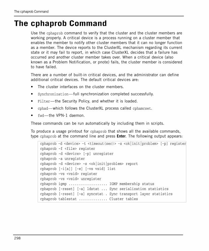
The cphaprob Command
298
The cphaprob CommandUse the cphaprob command to verify that the cluster and the cluster members are working properly. A critical device is a process running on a cluster member that enables the member to notify other cluster members that it can no longer function as a member. The device reports to the ClusterXL mechanism regarding its current state or it may fail to report, in which case ClusterXL decides that a failure has occurred and another cluster member takes over. When a critical device (also known as a Problem Notification, or pnote) fails, the cluster member is considered to have failed.
There are a number of built-in critical devices, and the administrator can define additional critical devices. The default critical devices are:
• The cluster interfaces on the cluster members.
• Synchronization—full synchronization completed successfully.
• Filter—the Security Policy, and whether it is loaded.
• cphad—which follows the ClusterXL process called cphamcset.
• fwd—the VPN-1 daemon.
These commands can be run automatically by including them in scripts.
To produce a usage printout for cphaprob that shows all the available commands, type cphaprob at the command line and press Enter. The following output appears:
cphaprob -d <device> -t <timeout(sec)> -s <ok|init|problem> [-p] registercphaprob -f <file> registercphaprob -d <device> [-p] unregistercphaprob -a unregistercphaprob -d <device> -s <ok|init|problem> reportcphaprob [-i[a]] [-e] [-vs vsid] listcphaprob -vs <vsid> registercphaprob -vs <vsid> unregistercphaprob igmp ................... IGMP membership statuscphaprob [-reset] [-a] ldstat ... Sync serialization statisticscphaprob [-reset] [-a] syncstat . Sync transport layer statisticscphaprob tablestat .............. Cluster tables

The cphaprob Command
Chapter 10 Command Line Reference 299
The following table describes the various command options:
Argument Description
[-vs vsid] stat View the status all cluster members or for a specific Virtual System.
[-a] [-vs vsid] if View the state of the cluster member interfaces and the virtual cluster interfaces.
[-i[a]] [-e] list View the list of critical devices on a cluster member, and of all the other machines in the cluster.
-d <device> -t <timeout (sec) > -s <ok | init | problem> [-p] register
Register <device> as a critical process, and add it to the list of devices that must be running for the cluster member to be considered active.
-f <file> register Register all the user defined critical devices listed in <file>.
-d <device> [-p] unregister Unregister a user defined <device> as a critical process. This means that this device is no longer considered critical.
-a unregister Unregister all user defined devices
-d <device> -s <ok | init | problem > report
Report the status of a user defined critical device to ClusterXL.
[-reset] ldstat View sync serialization statistics
[-reset] syncstat View sync transport layer statistics
savepnotes Saves problem notifications
tablestat Displays interfaces and IP addresses for each cluster member

The cphaprob Command
300

January 2008 301
Index
Symbols$FWDIR/conf/resctrl 226
AACE/Server 118Active/Standby Bridge
Mode 167, 212Administrator 140
Permissions 141Anti-spoofing 111Authentication 71, 88, 114, 191
Client/Session 120Radius 114SecurID 115TACAS 115
BBridge Mode
Active/Standby 167, 212Cluster configuration 209Clusters 164Spanning Tree Protocol 165Virtual Systems 30
Bundle license 129
CCapacity optimization 72, 89,
97, 192Client/Session
Authentication 120Cluster Type 199Clusters 52, 147
Active/Standby Bridge Mode 167, 212
Bridge Mode 164, 209
Changing Management IP or subnet 192
Changing type 199Configuring 172, 181Creating new 172Dedicated management
interface 179Delete member 195Dynamic routing 218High availability 52, 154,
201Interfaces 177, 186Internal communication
network 153, 192IP address 153Layer-2 segment 215Members 175, 183, 193Modifying 181Monitoring VLANS 217NAT 190Overview 148Planning 152Remote access 191SIC trust 176Spanning Tree Bridge
Mode 165Supported
environments 151Synchronization
network 152Topology 187Type 148Upgrade member 196Virtual Switch 170Virtual System Load
Sharing 53, 156, 204Virtual System states 159VPN 191Wizard 172
Clusters in VSX 147CMA, see Customer Management
Add-onContext 41Core network 169, 253cphaprob 298cpqoc
class del 234cpqos 233
class add 233install 234stats 235uninstall 234
Creation Templates 59Customer 137
Administrator 140Configuring 137Global policy 139GUI Client 142Permissions 141Wizard 137
Customer Management Add-on 126, 137
Configuring 143
DData center 258Debug 264
Per Virtual System 264Dedicated management
interface 28, 63Differentiated services 229, 236diffserve, see Differentiated
services 229Dynamic routing 51, 101, 254
Clusters 218
EEnterprise deployment 253External interface 73
Ffw 274
302
getifs 275monitor 276tab 277
fw resctrlenforce 284monitor 285traffic_stat 285
GGlobal objects 139
HHigh Availability
Per Virtual System 202, 204High availability 154
Per Virtual System 155VSX gateway 154
IInterface 107
Configuring 107Define 61Delete 113Separate 59Shared 59Topology 110
Interfaces 33Physical 35Unnumbered 36VLAN 35Warp 35
Internal communication network 153
Internal interface 73
LLicense 127Logs 71, 88, 97, 191
MMain CMA 126Management plug-ins 143MDG, see Multi-Domain GUIMDS, see Multi-Domain ServerMonitoring Cluster VLANS 217Multicast restrictions 111Multi-Domain GUI 126Multi-Domain Server 39, 126,
134Additional 135Installing 134
NNAT 50, 87, 121, 190
OOverlapping IP address 48
PPer Virtual System High
Availability 202, 204Per Virtual System high
availability 155Plug-ins 143Provider-1 39, 125, 256
Administrator 140License 127Permissions 141Virtual Router 145Virtual Switch 145Virtual System 145
PVST+ Load Sharing 166, 211
QQoS 228
Configuring 233Latency 230
Management 231Prioritization 229RED 231Wred 231
QosGlobal Scope 230
Quality of Service, see QOS
RRadius 116Remote Access 71, 88Resource Control 222
CPU resource 227Enable/Disable 225Enforcer 223Monitor 223Priorities 224, 226Weight 224
Route propagation 47Routing 45
Between Virtual Systems 46Dynamic routing 51Overlapping IP 48Propagation 47Source-based routing 49
SSecure Internal
Communication 40SecurID 118Separate interfaces 59Shared interface 59SIC trust 40, 60, 67SIC, see Secure Internal
CommunicationSiteManager-1 39, 125SmartCenter server 38SmartDefense 139SmartView Monitor 123Source-based routing 49, 99Spanning Tree Protocol
Limitations 165Spanning Tree Protocol Bridge
Mode 165Configuration 210

303
STP Bridge Mode, see Spanning Tree Bridge Mode
STP, see Spanning Tree Bridge Mode
Synchronization network 152
TTACAS 116Topology 69Troubleshooting 261
General steps 262
UUnnumbered interfaces 36
VVirtual Devices 29Virtual Router 31, 90
Configuring 94Delete 98Topology 96Wizard 92
Virtual Switch 32, 102Configuring 104Delete 106Topology 105Wizard 103
Virtual System 29, 73Bridge Mode 30, 78, 81Configuring 75, 83Creation templates 59Custom 79, 81Delete 89NAT 87Separate interface 77, 78Shared interface 77Topology 85, 93Wizard 75
Virtual System Load Sharing 53, 156, 204
Conceptual overview 157Distribute Virtual
Systems 206
Priority 158Requirements 156States 159Weight 158
VLAN 168VPN 71, 88VRF 41VSLS, see Virtual System Load
SharingVSX
Clusters 147, 149Configuring 56Dedicated management
interface 28Features & benefits 21License 127Management 37Management interface 28Overview 18Provisioning 133Routing 45Typical environments 22
vsxfetch 279fetchvs 280get 281set 281sic reset 283start_dr 283stat 282
VSX Gateway 25Configuring 57Management connections 25Recovery 72Topology 69Wizard 57
VSX gateway High availability 154
VSX high availability 154, 201vsx resctrl
monitor 225reset 285start 286stat 227, 286
VSX Resource Control 222VSX/CMA bundle license 129vsx_util 289
activate_plugin 290add_member 193, 291add_member_reconf 291change_mgmt_ip 292
change_mgmt_private_net 292
change_mgmt_subnet 293convert_cluster 293reconfigure 198, 294redistribute_vsls 207, 294remove_member 195, 295upgrade 197, 295view_vs_conf 295vsls 297
WWarp interfaces 35

304

305
THIRD PARTY TRADEMARKS AND COPYRIGHTS
Entrust is a registered trademark of Entrust Technologies, Inc. in the United States and other countries. Entrust’s logos and Entrust product and service names are also trademarks of Entrust Technologies, Inc. Entrust Technologies Limited is a wholly owned subsidiary of Entrust Technologies, Inc. FireWall-1 and SecuRemote incorporate certificate management technology from Entrust.
Verisign is a trademark of Verisign Inc.
The following statements refer to those portions of the software copyrighted by University of Michigan. Portions of the software copyright © 1992-1996 Regents of the University of Michigan. All rights reserved. Redistribution and use in source and binary forms are permitted provided that this notice is preserved and that due credit is given to the University of Michigan at Ann Arbor. The name of the University may not be used to endorse or promote products derived from this software without specific prior written permission. This software is provided “as is” without express or implied warranty. Copyright © Sax Software (terminal emulation only).
The following statements refer to those portions of the software copyrighted by Carnegie Mellon University.
Copyright 1997 by Carnegie Mellon University. All Rights Reserved.
Permission to use, copy, modify, and distribute this software and its documentation for any purpose and without fee is hereby granted, provided that the above copyright notice appear in all copies and that both that copyright notice and this permission notice appear in supporting documentation, and that the name of CMU not be used in advertising or publicity pertaining to distribution of the software without specific, written prior permission.CMU DISCLAIMS ALL WARRANTIES WITH REGARD TO THIS SOFTWARE, INCLUDING ALL IMPLIED WARRANTIES OF MERCHANTABILITY AND FITNESS, IN NO EVENT SHALL CMU BE LIABLE FOR ANY SPECIAL, INDIRECT OR CONSEQUENTIAL DAMAGES OR ANY DAMAGES WHATSOEVER RESULTING FROM LOSS OF USE, DATA OR PROFITS, WHETHER IN AN ACTION OF CONTRACT, NEGLIGENCE OR OTHER TORTIOUS ACTION, ARISING OUT OF OR IN CONNECTION WITH THE USE OR PERFORMANCE OF THIS SOFTWARE.
The following statements refer to those portions of the software copyrighted by The Open Group.
THE SOFTWARE IS PROVIDED "AS IS", WITHOUT WARRANTY OF ANY KIND, EXPRESS OR IMPLIED, INCLUDING BUT NOT LIMITED TO THE WARRANTIES OF MERCHANTABILITY, FITNESS FOR A PARTICULAR PURPOSE AND NONINFRINGEMENT. IN NO EVENT SHALL THE OPEN GROUP BE LIABLE FOR ANY CLAIM, DAMAGES OR OTHER LIABILITY, WHETHER IN AN ACTION OF CONTRACT, TORT OR OTHERWISE, ARISING FROM, OUT OF OR IN CONNECTION WITH THE SOFTWARE OR THE USE OR OTHER DEALINGS IN THE SOFTWARE.
The following statements refer to those portions of the software copyrighted by The OpenSSL Project. This product includes software developed by the OpenSSL Project for use in the OpenSSL Toolkit (http://www.openssl.org/).
THIS SOFTWARE IS PROVIDED BY THE OpenSSL PROJECT ``AS IS'' AND ANY * EXPRESSED OR IMPLIED WARRANTIES, INCLUDING, BUT NOT LIMITED TO, THE IMPLIED WARRANTIES OF MERCHANTABILITY AND FITNESS FOR A PARTICULAR PURPOSE ARE DISCLAIMED. IN NO EVENT SHALL THE OpenSSL PROJECT OR ITS CONTRIBUTORS BE LIABLE FOR ANY DIRECT, INDIRECT, INCIDENTAL, SPECIAL, EXEMPLARY, OR CONSEQUENTIAL DAMAGES (INCLUDING, BUT NOT LIMITED TO, PROCUREMENT OF SUBSTITUTE GOODS OR SERVICES; LOSS OF USE, DATA, OR PROFITS; OR BUSINESS INTERRUPTION) HOWEVER CAUSED AND ON ANY THEORY OF LIABILITY, WHETHER IN CONTRACT, STRICT LIABILITY, OR TORT (INCLUDING NEGLIGENCE OR OTHERWISE) ARISING IN ANY WAY OUT OF THE USE OF THIS SOFTWARE, EVEN IF ADVISED OF THE POSSIBILITY OF SUCH DAMAGE.
The following statements refer to those portions of the software copyrighted by Eric Young. THIS SOFTWARE IS PROVIDED BY ERIC YOUNG ``AS IS'' AND ANY EXPRESS OR IMPLIED WARRANTIES, INCLUDING, BUT NOT LIMITED TO, THE IMPLIED WARRANTIES OF MERCHANTABILITY AND FITNESS FOR A PARTICULAR PURPOSE ARE DISCLAIMED. IN NO EVENT SHALL THE AUTHOR OR CONTRIBUTORS BE LIABLE FOR ANY DIRECT, INDIRECT, INCIDENTAL, SPECIAL, EXEMPLARY, OR CONSEQUENTIAL DAMAGES (INCLUDING, BUT NOT LIMITED TO, PROCUREMENT OF SUBSTITUTE GOODS OR SERVICES; LOSS OF USE, DATA, OR PROFITS; OR BUSINESS INTERRUPTION) HOWEVER CAUSED AND ON ANY THEORY OF LIABILITY, WHETHER IN CONTRACT, STRICT LIABILITY, OR TORT (INCLUDING NEGLIGENCE OR OTHERWISE) ARISING IN ANY WAY OUT OF THE USE OF THIS SOFTWARE, EVEN IF ADVISED OF THE POSSIBILITY OF SUCH DAMAGE. Copyright © 1998 The Open Group.
306
The following statements refer to those portions of the software copyrighted by Jean-loup Gailly and Mark Adler Copyright (C) 1995-2002 Jean-loup Gailly and Mark Adler. This software is provided 'as-is', without any express or implied warranty. In no event will the authors be held liable for any damages arising from the use of this software. Permission is granted to anyone to use this software for any purpose, including commercial applications, and to alter it and redistribute it freely, subject to the following restrictions:
1. The origin of this software must not be misrepresented; you must not claim that you wrote the original software. If you use this software in a product, an acknowledgment in the product documentation would be appreciated but is not required.
2. Altered source versions must be plainly marked as such, and must not be misrepresented as being the original software.
3. This notice may not be removed or altered from any source distribution.
The following statements refer to those portions of the software copyrighted by the Gnu Public License. This program is free software; you can redistribute it and/or modify it under the terms of the GNU General Public License as published by the Free Software Foundation; either version 2 of the License, or (at your option) any later version. This program is distributed in the hope that it will be useful, but WITHOUT ANY WARRANTY; without even the implied warranty of MERCHANTABILITY or FITNESS FOR A PARTICULAR PURPOSE. See the GNU General Public License for more details.You should have received a copy of the GNU General Public License along with this program; if not, write to the Free Software Foundation, Inc., 675 Mass Ave, Cambridge, MA 02139, USA.
The following statements refer to those portions of the software copyrighted by Thai Open Source Software Center Ltd and Clark Cooper Copyright (c) 2001, 2002 Expat maintainers. Permission is hereby granted, free of charge, to any person obtaining a copy of this software and associated documentation files (the "Software"), to deal in the Software without restriction, including without limitation the rights to use, copy, modify, merge, publish, distribute, sublicense, and/or sell copies of the Software, and to permit persons to whom the Software is furnished to do so, subject to the following conditions: The above copyright notice and this permission notice shall be included in all copies or substantial portions of the Software. THE SOFTWARE IS PROVIDED "AS IS", WITHOUT WARRANTY OF ANY KIND, EXPRESS OR IMPLIED, INCLUDING BUT NOT LIMITED TO THE WARRANTIES OF MERCHANTABILITY, FITNESS FOR A PARTICULAR PURPOSE AND NONINFRINGEMENT. IN NO EVENT SHALL THE AUTHORS OR COPYRIGHT HOLDERS BE LIABLE FOR ANY CLAIM, DAMAGES OR OTHER LIABILITY, WHETHER IN AN ACTION OF CONTRACT, TORT OR OTHERWISE, ARISING FROM, OUT OF OR IN CONNECTION WITH THE SOFTWARE OR THE USE OR OTHER DEALINGS IN THE SOFTWARE.GDChart is free for use in your applications and for chart generation. YOU MAY NOT re-distribute or represent the code as your own. Any re-distributions of the code MUST reference the author, and include any and all original documentation. Copyright. Bruce Verderaime. 1998, 1999, 2000, 2001. Portions copyright 1994, 1995, 1996, 1997, 1998, 1999, 2000, 2001, 2002 by Cold Spring Harbor Laboratory. Funded under Grant P41-RR02188 by the National Institutes of Health. Portions copyright 1996, 1997, 1998, 1999, 2000, 2001, 2002 by Boutell.Com, Inc. Portions relating to GD2 format copyright 1999, 2000, 2001, 2002 Philip Warner. Portions relating to PNG copyright 1999, 2000, 2001, 2002 Greg Roelofs. Portions relating to gdttf.c copyright 1999, 2000, 2001, 2002 John Ellson ([email protected]). Portions relating to gdft.c copyright 2001, 2002 John Ellson ([email protected]). Portions relating to JPEG and to color quantization copyright 2000, 2001, 2002, Doug Becker and copyright (C) 1994, 1995, 1996, 1997, 1998, 1999, 2000, 2001, 2002, Thomas G. Lane. This software is based in part on the work of the Independent JPEG Group. See the file README-JPEG.TXT for more information. Portions relating to WBMP copyright 2000, 2001, 2002 Maurice Szmurlo and Johan Van den Brande. Permission has been granted to copy, distribute and modify gd in any context without fee, including a commercial application, provided that this notice is present in user-accessible supporting documentation. This does not affect your ownership of the derived work itself, and the intent is to assure proper credit for the authors of gd, not to interfere with your productive use of gd. If you have questions, ask. "Derived works" includes all programs that utilize the library. Credit must be given in user-accessible documentation. This software is provided "AS IS." The copyright holders disclaim all warranties, either express or implied, including but not limited to implied warranties of merchantability and fitness for a particular purpose, with respect to this code and accompanying documentation. Although their code does not appear in gd 2.0.4, the authors wish to thank David Koblas, David Rowley, and Hutchison Avenue Software Corporation for their prior contributions.
Licensed under the Apache License, Version 2.0 (the "License"); you may not use this file except in compliance with the License. You may obtain a copy of the License at http://www.apache.org/licenses/LICENSE-2.0
The curl license
COPYRIGHT AND PERMISSION NOTICE
Copyright (c) 1996 - 2004, Daniel Stenberg, <[email protected]>.All rights reserved.
Permission to use, copy, modify, and distribute this software for any purpose
with or without fee is hereby granted, provided that the above copyright
notice and this permission notice appear in all copies.

307
THE SOFTWARE IS PROVIDED "AS IS", WITHOUT WARRANTY OF ANY KIND, EXPRESS OR IMPLIED, INCLUDING BUT NOT LIMITED TO THE WARRANTIES OF MERCHANTABILITY, FITNESS FOR A PARTICULAR PURPOSE AND NONINFRINGEMENT OF THIRD PARTY RIGHTS. IN NO EVENT SHALL THE AUTHORS OR COPYRIGHT HOLDERS BE LIABLE FOR ANY CLAIM, DAMAGES OR OTHER LIABILITY, WHETHER IN AN ACTION OF CONTRACT, TORT OR OTHERWISE, ARISING FROM, OUT OF OR IN CONNECTION WITH THE SOFTWARE OR THE USE OR OTHER DEALINGS IN THE SOFTWARE.
Except as contained in this notice, the name of a copyright holder shall not be used in advertising or otherwise to promote the sale, use or other dealings in this Software without prior written authorization of the copyright holder.
The PHP License, version 3.0
Copyright (c) 1999 - 2004 The PHP Group. All rights reserved.
Redistribution and use in source and binary forms, with or without modification, is permitted provided that the following conditions are met:
1. Redistributions of source code must retain the above copyright notice, this list of conditions and the following disclaimer.
2. Redistributions in binary form must reproduce the above copyright notice, this list of conditions and the following disclaimer in the documentation and/or other materials provided with the distribution.
3. The name "PHP" must not be used to endorse or promote products derived from this software without prior written permission. For written permission, please contact [email protected].
4. Products derived from this software may not be called "PHP", nor may "PHP" appear in their name, without prior written permission from [email protected]. You may indicate that your software works in conjunction with PHP by saying "Foo for PHP" instead of calling it "PHP Foo" or "phpfoo"
5. The PHP Group may publish revised and/or new versions of the license from time to time. Each version will be given a distinguishing version number. Once covered code has been published under a particular version of the license, you may always continue to use it under the terms of that version. You may also choose to use such covered code under the terms of any subsequent version of the license published by the PHP Group. No one other than the PHP Group has the right to modify the terms applicable to covered code created under this License.
6. Redistributions of any form whatsoever must retain the following acknowledgment:
"This product includes PHP, freely available from <http://www.php.net/>".
THIS SOFTWARE IS PROVIDED BY THE PHP DEVELOPMENT TEAM ``AS IS'' AND ANY EXPRESSED OR IMPLIED WARRANTIES, INCLUDING, BUT NOT LIMITED TO, THE IMPLIED WARRANTIES OF MERCHANTABILITY AND FITNESS FOR A PARTICULAR PURPOSE ARE DISCLAIMED. IN NO EVENT SHALL THE PHP DEVELOPMENT TEAM OR ITS CONTRIBUTORS BE LIABLE FOR ANY DIRECT, INDIRECT, INCIDENTAL, SPECIAL, EXEMPLARY, OR CONSEQUENTIAL DAMAGES (INCLUDING, BUT NOT LIMITED TO, PROCUREMENT OF SUBSTITUTE GOODS OR SERVICES; LOSS OF USE, DATA, OR PROFITS; OR BUSINESS INTERRUPTION) HOWEVER CAUSED AND ON ANY THEORY OF LIABILITY, WHETHER IN CONTRACT, STRICT LIABILITY, OR TORT (INCLUDING NEGLIGENCE OR OTHERWISE) ARISING IN ANY WAY OUT OF THE USE OF THIS SOFTWARE, EVEN IF ADVISED OF THE POSSIBILITY OF SUCH DAMAGE.
This software consists of voluntary contributions made by many individuals on behalf of the PHP Group. The PHP Group can be contacted via Email at [email protected].
For more information on the PHP Group and the PHP project, please see <http://www.php.net>. This product includes the Zend Engine, freely available at <http://www.zend.com>.
This product includes software written by Tim Hudson ([email protected]).
THIS SOFTWARE IS PROVIDED BY THE COPYRIGHT HOLDERS AND CONTRIBUTORS "AS IS" AND ANY EXPRESS OR IMPLIED WARRANTIES, INCLUDING, BUT NOT LIMITED TO, THE IMPLIED WARRANTIES OF MERCHANTABILITY AND FITNESS FOR A PARTICULAR PURPOSE ARE DISCLAIMED. IN NO EVENT SHALL THE COPYRIGHT OWNER OR CONTRIBUTORS BE LIABLE FOR ANY DIRECT, INDIRECT, INCIDENTAL, SPECIAL, EXEMPLARY, OR CONSEQUENTIAL DAMAGES (INCLUDING, BUT NOT LIMITED TO, PROCUREMENT OF SUBSTITUTE GOODS OR SERVICES; LOSS OF USE, DATA, OR PROFITS; OR BUSINESS
INTERRUPTION) HOWEVER CAUSED AND ON ANY THEORY OF LIABILITY, WHETHER IN CONTRACT, STRICT LIABILITY, OR TORT (INCLUDING NEGLIGENCE OR OTHERWISE) ARISING IN ANY WAY OUT OF THE USE OF THIS SOFTWARE, EVEN IF ADVISED OF THE POSSIBILITY OF SUCH DAMAGE.
Copyright (c) 1998, 1999, 2000 Thai Open Source Software Center Ltd

308
Permission is hereby granted, free of charge, to any person obtaining a copy of this software and associated documentation files (the "Software"), to deal in the Software without restriction, including without limitation the rights to use, copy, modify, merge, publish, distribute, sublicense, and/or sell copies of the Software, and to permit persons to whom the Software is furnished to do so, subject to the following conditions: The above copyright notice and this permission notice shall be included in all copies or substantial portions of the Software.
THE SOFTWARE IS PROVIDED "AS IS", WITHOUT WARRANTY OF ANY KIND, EXPRESS OR IMPLIED, INCLUDING BUT NOT LIMITED TO THE WARRANTIES OF MERCHANTABILITY, FITNESS FOR A PARTICULAR PURPOSE AND NONINFRINGEMENT. IN NO EVENT SHALL THE AUTHORS OR COPYRIGHT HOLDERS BE LIABLE FOR ANY CLAIM, DAMAGES OR OTHER LIABILITY, WHETHER IN AN ACTION OF CONTRACT, TORT OR OTHERWISE, ARISING FROM, OUT OF OR IN CONNECTION WITH THE SOFTWARE OR THE USE OR OTHER DEALINGS IN THE SOFTWARE.
Copyright © 2003, 2004 NextHop Technologies, Inc. All rights reserved.
Confidential Copyright Notice
Except as stated herein, none of the material provided as a part of this document may be copied, reproduced, distrib-uted, republished, downloaded, displayed, posted or transmitted in any form or by any means, including, but not lim-ited to, electronic, mechanical, photocopying, recording, or otherwise, without the prior written permission of NextHop Technologies, Inc. Permission is granted to display, copy, distribute and download the materials in this doc-ument for personal, non-commercial use only, provided you do not modify the materials and that you retain all copy-right and other proprietary notices contained in the materials unless otherwise stated. No material contained in this document may be "mirrored" on any server without written permission of NextHop. Any unauthorized use of any material contained in this document may violate copyright laws, trademark laws, the laws of privacy and publicity, and communications regulations and statutes. Permission terminates automatically if any of these terms or condi-tions are breached. Upon termination, any downloaded and printed materials must be immediately destroyed.
Trademark Notice
The trademarks, service marks, and logos (the "Trademarks") used and displayed in this document are registered and unregistered Trademarks of NextHop in the US and/or other countries. The names of actual companies and products mentioned herein may be Trademarks of their respective owners. Nothing in this document should be construed as granting, by implication, estoppel, or otherwise, any license or right to use any Trademark displayed in the document. The owners aggressively enforce their intellectual property rights to the fullest extent of the law. The Trademarks may not be used in any way, including in advertising or publicity pertaining to distribution of, or access to, materials in
this document, including use, without prior, written permission. Use of Trademarks as a "hot" link to any website is prohibited unless establishment of such a link is approved in advance in writing. Any questions concerning the use of these Trademarks should be referred to NextHop at U.S. +1 734 222 1600.
U.S. Government Restricted Rights
The material in document is provided with "RESTRICTED RIGHTS." Software and accompanying documentation are provided to the U.S. government ("Government") in a transaction subject to the Federal Acquisition Regulations with Restricted Rights. The Government's rights to use, modify, reproduce, release, perform, display or disclose are
restricted by paragraph (b)(3) of the Rights in Noncommercial Computer Software and Noncommercial Computer Soft-ware Documentation clause at DFAR 252.227-7014 (Jun 1995), and the other restrictions and terms in paragraph (g)(3)(i) of Rights in Data-General clause at FAR 52.227-14, Alternative III (Jun 87) and paragraph (c)(2) of the Commer-cial
Computer Software-Restricted Rights clause at FAR 52.227-19 (Jun 1987).
Use of the material in this document by the Government constitutes acknowledgment of NextHop's proprietary rights in them, or that of the original creator. The Contractor/Licensor is NextHop located at 1911 Landings Drive, Mountain View, California 94043. Use, duplication, or disclosure by the Government is subject to restrictions as set forth in applicable laws and regulations.
Disclaimer Warranty Disclaimer Warranty Disclaimer Warranty Disclaimer Warranty
THE MATERIAL IN THIS DOCUMENT IS PROVIDED "AS IS" WITHOUT WARRANTIES OF ANY KIND EITHER EXPRESS OR IMPLIED. TO THE FULLEST EXTENT POSSIBLE PURSUANT TO THE APPLICABLE LAW, NEXTHOP DISCLAIMS ALL WARRANTIES,
EXPRESSED OR IMPLIED, INCLUDING, BUT NOT LIMITED TO, IMPLIED WARRANTIES OF MERCHANTABILITY, FITNESS FOR A PARTICULAR PURPOSE, NON INFRINGEMENT OR OTHER VIOLATION OF RIGHTS. NEITHER NEXTHOP NOR ANY OTHER PROVIDER OR DEVELOPER OF MATERIAL CONTAINED IN THIS DOCUMENT WARRANTS OR MAKES ANY REPRESEN-TATIONS REGARDING THE USE, VALIDITY, ACCURACY, OR RELIABILITY OF, OR THE RESULTS OF THE USE OF, OR OTHERWISE RESPECTING, THE MATERIAL IN THIS DOCUMENT.
Limitation of Liability

309
UNDER NO CIRCUMSTANCES SHALL NEXTHOP BE LIABLE FOR ANY DIRECT, INDIRECT, SPECIAL, INCIDENTAL OR CONSEQUENTIAL DAMAGES, INCLUDING, BUT NOT LIMITED TO, LOSS OF DATA OR PROFIT, ARISING OUT OF THE USE, OR THE INABILITY TO USE, THE MATERIAL IN THIS DOCUMENT, EVEN IF NEXTHOP OR A NEXTHOP AUTHORIZED REPRESENTATIVE HAS ADVISED OF THE POSSIBILITY OF SUCH DAMAGES. IF YOUR USE OF MATERIAL FROM THIS DOCUMENT RESULTS IN THE NEED FOR SERVICING, REPAIR OR CORRECTION OF EQUIPMENT OR DATA, YOU ASSUME ANY COSTS THEREOF. SOME STATES DO NOT ALLOW THE EXCLUSION OR LIMITATION OF INCIDENTAL OR CONSEQUENTIAL DAMAGES, SO THE ABOVE LIMITATION OR EXCLUSION MAY NOT FULLY APPLY TO YOU.
Copyright © ComponentOne, LLC 1991-2002. All Rights Reserved.
BIND: ISC Bind (Copyright (c) 2004 by Internet Systems Consortium, Inc. ("ISC"))
Copyright 1997-2001, Theo de Raadt: the OpenBSD 2.9 Release
PCRE LICENCE
PCRE is a library of functions to support regular expressions whose syntax and semantics are as close as possible to those of the Perl 5 language. Release 5 of PCRE is distributed under the terms of the "BSD" licence, as specified below. The documentation for PCRE, supplied in the "doc" directory, is distributed under the same terms as the software itself.
Written by: Philip Hazel <[email protected]>
University of Cambridge Computing Service, Cambridge, England. Phone:
+44 1223 334714.
Copyright (c) 1997-2004 University of Cambridge All rights reserved.
Redistribution and use in source and binary forms, with or without modification, are permitted provided that the following conditions are met:
* Redistributions of source code must retain the above copyright notice, this list of conditions and the following disclaimer.
* Redistributions in binary form must reproduce the above copyright notice, this list of conditions and the following disclaimer in the documentation and/or other materials provided with the distribution.
* Neither the name of the University of Cambridge nor the names of its contributors may be used to endorse or promote products derived from this software without specific prior written permission.
THIS SOFTWARE IS PROVIDED BY THE COPYRIGHT HOLDERS AND CONTRIBUTORS "AS IS" AND ANY EXPRESS OR IMPLIED WARRANTIES, INCLUDING, BUT NOT LIMITED TO, THE IMPLIED WARRANTIES OF MERCHANTABILITY AND FITNESS FOR A PARTICULAR PURPOSE ARE DISCLAIMED. IN NO EVENT SHALL THE COPYRIGHT OWNER OR CONTRIBUTORS BE LIABLE FOR ANY DIRECT, INDIRECT, INCIDENTAL, SPECIAL, EXEMPLARY, OR CONSEQUENTIAL DAMAGES (INCLUDING, BUT NOT LIMITED TO, PROCUREMENT OF SUBSTITUTE GOODS OR SERVICES; LOSS OF USE, DATA, OR PROFITS; OR BUSINESS INTERRUPTION) HOWEVER CAUSED AND ON ANY THEORY OF LIABILITY, WHETHER IN CONTRACT, STRICT LIABILITY, OR TORT (INCLUDING NEGLIGENCE OR OTHERWISE) ARISING IN ANY WAY OUT OF THE USE OF THIS SOFTWARE, EVEN IF ADVISED OF THE POSSIBILITY OF SUCH DAMAGE.
Eventia Reporter includes software whose copyright is owned by, or licensed from, MySQL AB.

310