vortex oem modbus specification
TRANSCRIPT

Approvals A. Beasley
1:
Date:
A. Summerfield 2:
Date:
© Crowcon 2008 file : \\crowconserver\departments\servicerepair\users\simon.neale\my documents\cd rom\manuals and datasheets\crowcon\fixed systems
manuals\vortex modbus.doc
Engineering Report
Doc No : GC012 Issue No : 2
Date : 29/01/2001 Page 1 of 44
Author : L J Mattsson & A Summerfield
Product Family : Fixed Systems Part No : Vortex Security Classification :
Report Title :
Vortex OEM MODBUS Specification

Engineering Report
Doc No:
GC012 Issue No: 2 Date: 5/10/2000 Page 2 of 44
© Crowcon 2008File : \\crowconserver\departments\servicerepair\users\simon.neale\my documents\cd rom\manuals and datasheets\crowcon\fixed systems manuals\vortex modbus.doc
Change History
Issue Change Author Date
1 First release taken from SIG07 issue 1.1 A.C.Beasley 6/03/2000
2 Simplified version for ease of customers incorporating changes
for node controller software version GCNCT1_1i1
L J Mattsson &
A Summerfield
29/01/2001

Engineering Report
Doc No:
GC012 Issue No: 2 Date: 5/10/2000 Page 3 of 44
© Crowcon 2008File : \\crowconserver\departments\servicerepair\users\simon.neale\my documents\cd rom\manuals and datasheets\crowcon\fixed systems manuals\vortex modbus.doc
Contents
1. INTRODUCTION..............................................................................................................................................5
1.1 SCOPE OF DOCUMENT ...................................................................................................................................5
1.2 ABBREVIATIONS AND DEFINITIONS ................................................................................................................5
2. ELECTRICAL & GENERAL DATA FORMAT SPECIFICATION ..............................................................6
2.1 ELECTRICAL .................................................................................................................................................6
2.2 PACKET FORMAT ..........................................................................................................................................6
2.3 PACKET DELIMITERS .....................................................................................................................................6
2.4 PACKET TYPES .............................................................................................................................................7
2.4.1 Query Packet ........................................................................................................................................7
2.4.2 Acknowledge Packet .............................................................................................................................7
2.4.3 Exception Packet ..................................................................................................................................7
3. SUPPORTED FUNCTION CODES ..................................................................................................................9
3.1 READ HOLDING REGISTERS (FUNCTION CODE 0X03). .....................................................................................9
3.2 PRESET MULTIPLE REGISTERS (FUNCTION CODE 0X10) ................................................................................ 10
3.3 MAXIMUM SIZE OF PACKETS ....................................................................................................................... 10
4. REGISTER DEFINITIONS ............................................................................................................................ 11
4.1 REGISTER GROUPS ...................................................................................................................................... 11
4.2 KEY FOR ACCESS RIGHTS ............................................................................................................................ 11
4.3 KEY FOR FUNDAMENTAL DATA TYPES ........................................................................................................ 11
4.4 BOOLEAN SETTINGS .................................................................................................................................... 12
4.5 MODBUS REGISTER MAP .......................................................................................................................... 13
4.5.1 System ................................................................................................................................................ 13
4.5.2 Detector 1 Configuration Map ............................................................................................................ 14
4.5.3 Detector 2 Configuration Map ............................................................................................................ 16
4.5.4 Detector 3 Configuration Map ............................................................................................................ 18
4.5.5 Detector 4 Configuration Map ............................................................................................................ 20
4.5.6 Detector 5 Configuration Map ............................................................................................................ 22 4.5.7 Detector 6 Configuration Map ............................................................................................................ 24
4.5.8 Detector 7 Configuration Map ............................................................................................................ 26
4.5.9 Detector 8 Configuration Map ............................................................................................................ 28
4.5.10 Detector 9 Configuration Map ............................................................................................................ 30
4.5.11 Detector 10 Configuration Map .......................................................................................................... 32
4.5.12 Detector 11 Configuration Map .......................................................................................................... 34
4.5.13 Detector 12 Configuration Map .......................................................................................................... 36
4.5.14 Detector 1 Normal Map ...................................................................................................................... 38
4.5.15 Detector 2 Normal Map ...................................................................................................................... 38
4.5.16 Detector 3 Normal Map ...................................................................................................................... 38
4.5.17 Detector 4 Normal Map ...................................................................................................................... 39 4.5.18 Detector 5 Normal Map ...................................................................................................................... 39
4.5.19 Detector 6 Normal Map ...................................................................................................................... 39
4.5.20 Detector 7 Normal Map ...................................................................................................................... 40
4.5.21 Detector 8 Normal Map ...................................................................................................................... 40
4.5.22 Detector 9 Normal Map ...................................................................................................................... 40
4.5.23 Detector 10 Normal Map .................................................................................................................... 41
4.5.24 Detector 11 Normal Map .................................................................................................................... 41
4.5.25 Detector 12 Normal Map .................................................................................................................... 41
5. SUPPLEMENTARY DEFINITIONS SUPPORTING MODBUS REGISTER MAP .................................... 42
5.1 SYSTEM REGISTERS .................................................................................................................................... 42
5.1.1 SYSTEM_STATUS Type ...................................................................................................................... 42
5.1.2 System Inhibits .................................................................................................................................... 42

Engineering Report
Doc No:
GC012 Issue No: 2 Date: 5/10/2000 Page 4 of 44
© Crowcon 2008File : \\crowconserver\departments\servicerepair\users\simon.neale\my documents\cd rom\manuals and datasheets\crowcon\fixed systems manuals\vortex modbus.doc
5.1.3 DETECTOR_ENABLE Type ............................................................................................................... 43
5.1.4 DETECTOR_TYPE ............................................................................................................................. 43 5.1.5 Detector Alarm Settings ...................................................................................................................... 43
5.1.6 DETECTOR_LEVEL Type .................................................................................................................. 43
5.1.7 DETECTOR_STATUS Type ................................................................................................................ 43
5.1.8 DETECTOR INHIBIT Type ................................................................................................................. 44

Engineering Report
Doc No:
GC012 Issue No: 2 Date: 5/10/2000 Page 5 of 44
© Crowcon 2008File : \\crowconserver\departments\servicerepair\users\simon.neale\my documents\cd rom\manuals and datasheets\crowcon\fixed systems manuals\vortex modbus.doc
1. Introduction
1.1 Scope of Document
This document specifies the MODBUS interface for use with Vortex products.
The MODBUS protocol defined in this interface document shall be used for both RS485 and RS232 hardware
interfaces.
1.2 Abbreviations and Definitions
Abbreviation Definition
CRC Cyclic Redundancy Check – this value is calculated from a string of data values and is used by the
recipient of the data string to check the string integrity.
DCS Distributed Control System
LSB Least significant byte/bit
ModBus
Register
Number
This term refers to the ModBus registers as defined in ref.2. A ModBus register can be any physical
size measured in words.
MSB Most significant byte/bit
PLC Programmable Logic Controller
RTU Remote Terminal Unit – In the ModBus protocol this refers to 8 bit bytes composed of 2 x 4 bit hex
characters.
Word A measure of data size associated with a particular ModBus register number. A word is equivalent to
2 bytes or 16 bits.

Engineering Report
Doc No:
GC012 Issue No: 2 Date: 5/10/2000 Page 6 of 44
© Crowcon 2008File : \\crowconserver\departments\servicerepair\users\simon.neale\my documents\cd rom\manuals and datasheets\crowcon\fixed systems manuals\vortex modbus.doc
2. Electrical & General Data Format Specification
2.1 Electrical
Communications with Vortex is via a 2 wire, half duplex RS485 link using the MODBUS protocol. The format of
each data byte transferred is 1 start bit, 8 data bits, 2 stop bits, no parity. Binary RTU (sometimes called ModBus-B)
format is used for each byte of data, rather than two ASCII characters. The speed of both transmission and reception is 9600 baud.
The MODBUS protocol defined in this specification is standard MODBUS, thus demands a fixed master / slave
relationship between communicating devices. MODBUS PLUS, which allows multiple master configurations is NOT
part of this specification.
The master / slave relationship is defined for each device in the table below.
Application Master / Slave Role
of Device
Communicating
Partner
Master / Slave role
of Partner
Vortex Slave VortexPC Windows set
up software OR DCS
Master
The following rules govern the master / slave relationship.
Slave devices shall only send any data when requested by a master, with a query packet specifically addressed to
the slave.
There shall be only one master device for each physical bus. This shall be the only device capable of initiating
communications.
Devices, which share the same physical bus, are identified by a unique digital address. The address can be set up at
configuration time using VortexPC.
2.2 Packet Format
All MODBUS packets are composed of data bytes and have the following format:
Byte Contents Range
1 Address of slave 1-247
2 Function code
3
.
.
N
Variable length data field
N+ 1 CRC low byte
N+ 2 CRC high byte
2.3 Packet Delimiters
The beginning of a packet, and end of a packet are determined by delimiters. The only delimiters in the ModBus
protocol are quiet intervals that are defined as follows: -

Engineering Report
Doc No:
GC012 Issue No: 2 Date: 5/10/2000 Page 7 of 44
© Crowcon 2008File : \\crowconserver\departments\servicerepair\users\simon.neale\my documents\cd rom\manuals and datasheets\crowcon\fixed systems manuals\vortex modbus.doc
Quiet Interval
Time (character
times) as per ref.2
Meaning
3.5 Start of packet
3.5 End of packet and potentially start of next packet.
< 3.5 at the end of
packet
Assume the data following on from the
shortened quiet interval is a continuation
of the message. If this is the wrong
assumption then the CRC check will
catch it.
MODBUS also defines a 1.5 character time quiet interval, where the incoming message should be flushed from the
receiver buffer and assume that the next data byte received after quiet period is the address of a new packet. This 1.5
character interval is NOT part of this Vortex MODBUS specification.
At 9600 baud a character interval is 1.146 mS.
After the “end of packet quiet interval” the next packet can start immediately but in practice this is not common
because of the time taken to “turn around” the RS 485 transceiver devices. In Vortex devices the interval between the end of a query packet and the start of an acknowledge packet from the Vortex device shall be in the range 50 to 400
mS.
Some packet types have a “number of bytes of data” field, which can be used as a cross check of packet validity but
should NOT be used as the delimiters because of the possibility of corruption.
2.4 Packet Types
2.4.1 Query Packet
A query packet is a packet generated by the bus master and addressed to a slave unit.
2.4.2 Acknowledge Packet
If the bus master generates a query packet addressed to a device, the device will generate an acknowledge packet,
which contains a response to the query.
The acknowledge packet‟s contents is specific to each function code and each is defined later.
If the packet from the master is incorrect in some way then the acknowledge packet is replaced by an exception packet
see below.
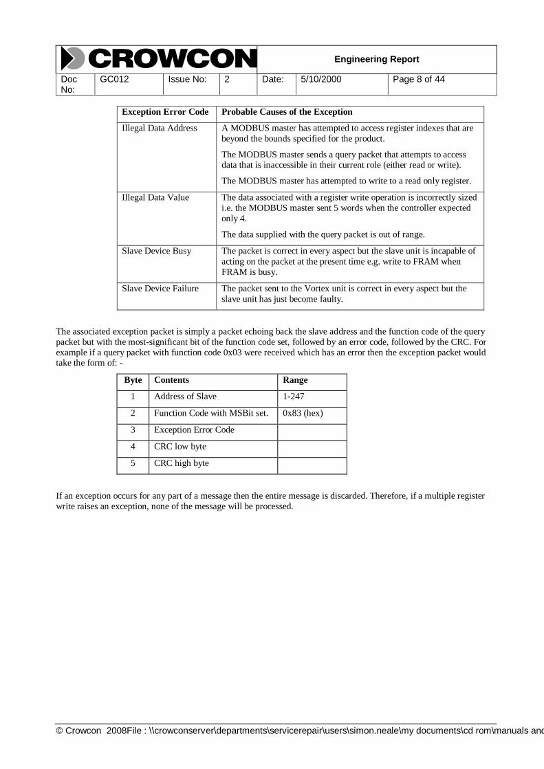
2.4.3 Exception Packet
The following circumstances will cause an exception packet to be generated in response to a query packet. The
exception packet contains the exception error code shown in the table.
Exception Error Code Probable Causes of the Exception
No response The MODBUS master has sent a data packet with an incorrect
MODBUS address to the Vortex unit.
The MODBUS master has sent a data packet with an incorrect CRC
to the Vortex unit.
Illegal Function The MODBUS master has sent a data packet to the Vortex unit that
contains a function code, which the Vortex unit is not programmed to respond to i.e. anything other than codes 0x03 or 0x10.
Engineering Report
Doc No:
GC012 Issue No: 2 Date: 5/10/2000 Page 8 of 44
© Crowcon 2008File : \\crowconserver\departments\servicerepair\users\simon.neale\my documents\cd rom\manuals and datasheets\crowcon\fixed systems manuals\vortex modbus.doc
Exception Error Code Probable Causes of the Exception
Illegal Data Address A MODBUS master has attempted to access register indexes that are
beyond the bounds specified for the product.
The MODBUS master sends a query packet that attempts to access data that is inaccessible in their current role (either read or write).
The MODBUS master has attempted to write to a read only register.
Illegal Data Value The data associated with a register write operation is incorrectly sized
i.e. the MODBUS master sent 5 words when the controller expected
only 4.
The data supplied with the query packet is out of range.
Slave Device Busy The packet is correct in every aspect but the slave unit is incapable of
acting on the packet at the present time e.g. write to FRAM when
FRAM is busy.
Slave Device Failure The packet sent to the Vortex unit is correct in every aspect but the
slave unit has just become faulty.
The associated exception packet is simply a packet echoing back the slave address and the function code of the query
packet but with the most-significant bit of the function code set, followed by an error code, followed by the CRC. For
example if a query packet with function code 0x03 were received which has an error then the exception packet would take the form of: -
Byte Contents Range
1 Address of Slave 1-247
2 Function Code with MSBit set. 0x83 (hex)
3 Exception Error Code
4 CRC low byte
5 CRC high byte
If an exception occurs for any part of a message then the entire message is discarded. Therefore, if a multiple register
write raises an exception, none of the message will be processed.

Engineering Report
Doc No:
GC012 Issue No: 2 Date: 5/10/2000 Page 9 of 44
© Crowcon 2008File : \\crowconserver\departments\servicerepair\users\simon.neale\my documents\cd rom\manuals and datasheets\crowcon\fixed systems manuals\vortex modbus.doc
3. Supported Function Codes
In Vortex systems only two function codes are implemented-
Function Code 03 (03 hex)- Read Holding Registers (single or multiple)
Function Code 16 (10 hex)- Preset (Write) Multiple Registers (single or multiple)
The data read from or written to a Vortex system can be any number of MODBUS registers in length (within the constraints of the maximum packet size). A MODBUS register is defined as being 16 bits wide. Register values are
sent in the order high byte followed by low byte.
The specific packet formats used in Vortex systems are as follows:
3.1 Read Holding Registers (Function Code 0x03).
Data format from MODBUS Master:
Byte Contents Range
1 Address of slave 1-247
2 Function code 3
3 Starting register high byte
4 Starting register low byte
5 Number of registers (N) high byte
6 Number of registers (N) low byte
7 CRC low byte
8 CRC high byte
Response from Vortex Unit:
Byte Contents Range
1 Address of slave 1-247
2 Function code 3
3 Byte count (n) of data that follows* (excluding
CRC).
4 First register data high byte
5 First register data low byte
Repeats for number of registers read
4 + n CRC low byte
5 + n CRC high byte
* See section 3.3 for notes on maximum size of packets

Engineering Report
Doc No:
GC012 Issue No: 2 Date: 5/10/2000 Page 10 of 44
© Crowcon 2008File : \\crowconserver\departments\servicerepair\users\simon.neale\my documents\cd rom\manuals and datasheets\crowcon\fixed systems manuals\vortex modbus.doc
3.2 Preset Multiple Registers (Function Code 0x10)
Data format from MODBUS Master:
Byte Contents Range
1 Address of Slave 1-247
2 Function Code 16 (decimal)
3 Starting Register High Byte
4 Starting Register Low Byte
5 Number of Registers High Byte
6 Number of Registers Low Byte
7 Byte Count of Data (n) excluding CRC
8 First Register data High Byte
9 First Register data Low Byte
..
..
8 + n CRC Low Byte
9 + n CRC High Byte
* See section 3.3 for notes on maximum size of packets
Response from Vortex Unit:
Byte Contents Range
1 Address of Slave 1-247
2 Function Code 16
3 Starting Register High Byte
4 Starting Register Low Byte
5 Number of Registers Preset
High Byte
6 Number of Registers Preset Low
Byte
7 CRC Low Byte
8 CRC High Byte
3.3 Maximum Size of Packets
In order to maintain compatibility with the maximum number of PLCs the maximum number of words that can be
transferred in a single ModBus transaction is limited to 100.

Engineering Report
Doc No:
GC012 Issue No: 2 Date: 5/10/2000 Page 11 of 44
© Crowcon 2008File : \\crowconserver\departments\servicerepair\users\simon.neale\my documents\cd rom\manuals and datasheets\crowcon\fixed systems manuals\vortex modbus.doc
4. Register Definitions
4.1 Register Groups
The data presented in the register address table is arranged in groups, according to the object to which the data relates
and its storage medium. The groups are as follows:-
System
Detector – Normal
Detector – Configuration
4.2 Key for Access Rights
The following access rights are defined for each register and are stated in the last column of the MODBUS register
map table:
Key: User Access Rights:
R R ead only access
B B oth read and write access
W W rite only access (zero when read)
4.3 Key for Fundamental Data Types
The storage size of a register location for simple, i.e. non-structured data types, is indicated as follows in the register
maps:
Key: Location Storage Size: Variable Format on MODBUS:
BOOL 8 bit integer, 0 = false, any other value = true Sign extended to 16 bits
INT8 Signed 8-bit integer Sign extended to 16 bits
INT16 Signed 16-bit integer No change
INT32 Signed 32-bit integer Occupies register pair, least significant 16 bits
in the 2nd word.
UINT8 Unsigned 8-bit integer Extended with leading 0s to 16 bits
UINT16 Unsigned 16-bit integer No change
UINT32 Unsigned integer () Occupies register pair, least significant 16 bits
in the 2nd word.
STRING xx Text string of fixed length xx bytes. There is no null terminator; null padded to fit
defined length.

Engineering Report
Doc No:
GC012 Issue No: 2 Date: 5/10/2000 Page 12 of 44
© Crowcon 2008File : \\crowconserver\departments\servicerepair\users\simon.neale\my documents\cd rom\manuals and datasheets\crowcon\fixed systems manuals\vortex modbus.doc
4.4 Boolean Settings
Booleans – flags which can take only values of TRUE and FALSE
Are defined to have the following numeric value; FALSE = 0000 Hex, TRUE = FFFF Hex.

Engineering Report
Doc No:
GC012 Issue No: 2 Date: 5/10/2000 Page 13 of 44
© Crowcon 2008File : \\crowconserver\departments\servicerepair\users\simon.neale\my documents\cd rom\manuals and datasheets\crowcon\fixed systems manuals\vortex modbus.doc
4.5 MODBUS Register Map
The following table defines the register address, the data type for that register and the access rights.
4.5.1 System
MODBUS Register:
Number. Identity
Typical
Setting:
Valid Range: Units: Number of
Registers:
Location Storage Size:
Access
1. Unit Type “Vortex” N/A N/A 8 String 16 R
9. Accept / Reset N/A N/A N/A 1 A dummy MODBUS word has to be supplied but is scrapped by the
MODBUS slave.
W
12. System Status N/A N/A N/A 1 UINT16 see SYSTEM_STATUS (5.1) R
13. Power Status OK OK = 0
| Main supply OK, battery low = 1
| Main supply fail, battery good = 2
| Main supply OK, battery
disconnected = 3
| Main supply fail, battery low = 4
| No Comms to Power Card = 5
N/A 1 UINT8 R
17. System Fault Inhibit False True = Inhibited
| False = Not Inhibited
N/A 1 BOOL see system inhibits (5.1.2) B
18. System Sounder Inhibit False True = Inhibited
| False = Not Inhibited
N/A 1 BOOL see system inhibits (5.1.2) B
33. Serial Number ”012345” N/A N/A 8 String 16 R
34. System Name “Didcot B
V1”
N/A N/A 8 String 16 R
39. Number of installed Detector
Inputs
12 1..12 N/A 1 UINT8 R
40. Number of installed Digital
Outputs
16 1..32 N/A 1 UNIT8 R

Engineering Report
Doc No:
GC012 Issue No: 2 Date: 5/10/2000 Page 14 of 44
© Crowcon 2008File : \\crowconserver\departments\servicerepair\users\simon.neale\my documents\cd rom\manuals and datasheets\crowcon\fixed systems manuals\vortex modbus.doc
4.5.2 Detector 1 Configuration Map
MODBUS Register:
Number. Identity
Typical
Setting:
Valid Range: Units: Number of
Registers:
Location Storage Size:
Access
110. Enable True True
| False
N/A 1 BOOL see DETECTOR_ENABLE (5.1.3) R
111. Type Gas Not Configured = 0
| Gas = 6
| Fire = 8
N/A 1 UINT8 see DETECTOR_TYPE (5.1.4) R
114. Alarm 1 Level 450 0 to 1000 where 1000 represents full
scale.
FS/1000 1 INT16 DETECTOR_LEVEL (5.1.6) and see section 5.1.5 R
115. Alarm 1 Transition Rising Rising = True
| Falling = False
N/A 1 BOOL and see section 5.1.5 R
116. Alarm 2 Level 550 0 to 1000 where 1000 represents full
scale.
FS/1000 1 INT16 DETECTOR_LEVEL (5.1.6) and see section 5.1.5 R
117. Alarm 2 Transition Rising Rising = True
| Falling = False
N/A 1 BOOL and see section 5.1.5 R
118. Alarm 3 Level 650 0 to 1000 where 1000 represents full
scale.
FS/1000 1 INT16 DETECTOR_LEVEL (5.1.6) and see section 5.1.5 R
119. Alarm 3 Transition Rising Rising = True
| Falling = False
N/A 1 BOOL and see section 5.1.5 R
122. Units %VOL | %LEL = 0
| %VOL = 1
| PPM = 2
| Fire = 3
N/A 1 UINT8 R

Engineering Report
Doc No:
GC012 Issue No: 2 Date: 5/10/2000 Page 15 of 44
© Crowcon 2008File : \\crowconserver\departments\servicerepair\users\simon.neale\my documents\cd rom\manuals and datasheets\crowcon\fixed systems manuals\vortex modbus.doc
MODBUS Register:
Number. Identity
Typical
Setting:
Valid Range: Units: Number of
Registers:
Location Storage Size:
Access
123. Range 0 to 10 | 0 to 1 = 9
| 0 to 2 = 10
| 0 to 2.5 = 11
| 0 to 5 = 12
| 0 to 10 = 13
| 0 to 20 = 14
| 0 to 25 = 15
| 0 to 50 = 16
| 0 to 100 = 17
| 0 to 200 = 18
| 0 to 250 = 19
| 0 to 500 = 20
| 0 to 1,000 = 21
| 0 to 2,000 = 22
| 0 to 2,500 = 23
| 0 to 5,000 = 24
| 0 to 10,000 = 25
N/A 1 UINT8 R
126. Identity “T 1BYP-
DCT”
ASCII characters N/A 4 String 8 R
Engineering Report
Doc No:
GC012 Issue No: 2 Date: 5/10/2000 Page 16 of 44
© Crowcon 2008File : \\crowconserver\departments\servicerepair\users\simon.neale\my documents\cd rom\manuals and datasheets\crowcon\fixed systems manuals\vortex modbus.doc
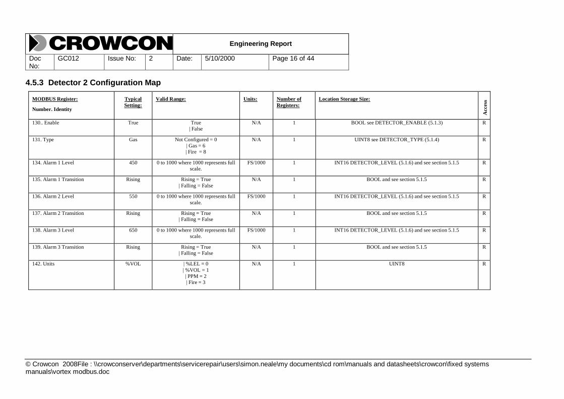
4.5.3 Detector 2 Configuration Map
MODBUS Register:
Number. Identity
Typical
Setting:
Valid Range: Units: Number of
Registers:
Location Storage Size:
Access
130.. Enable True True
| False
N/A 1 BOOL see DETECTOR_ENABLE (5.1.3) R
131. Type Gas Not Configured = 0
| Gas = 6
| Fire = 8
N/A 1 UINT8 see DETECTOR_TYPE (5.1.4) R
134. Alarm 1 Level 450 0 to 1000 where 1000 represents full
scale.
FS/1000 1 INT16 DETECTOR_LEVEL (5.1.6) and see section 5.1.5 R
135. Alarm 1 Transition Rising Rising = True
| Falling = False
N/A 1 BOOL and see section 5.1.5 R
136. Alarm 2 Level 550 0 to 1000 where 1000 represents full
scale.
FS/1000 1 INT16 DETECTOR_LEVEL (5.1.6) and see section 5.1.5 R
137. Alarm 2 Transition Rising Rising = True
| Falling = False
N/A 1 BOOL and see section 5.1.5 R
138. Alarm 3 Level 650 0 to 1000 where 1000 represents full
scale.
FS/1000 1 INT16 DETECTOR_LEVEL (5.1.6) and see section 5.1.5 R
139. Alarm 3 Transition Rising Rising = True
| Falling = False
N/A 1 BOOL and see section 5.1.5 R
142. Units %VOL | %LEL = 0
| %VOL = 1
| PPM = 2
| Fire = 3
N/A 1 UINT8 R

Engineering Report
Doc No:
GC012 Issue No: 2 Date: 5/10/2000 Page 17 of 44
© Crowcon 2008File : \\crowconserver\departments\servicerepair\users\simon.neale\my documents\cd rom\manuals and datasheets\crowcon\fixed systems manuals\vortex modbus.doc
MODBUS Register:
Number. Identity
Typical
Setting:
Valid Range: Units: Number of
Registers:
Location Storage Size:
Access
143. Range 0 to 10 | 0 to 1 = 9
| 0 to 2 = 10
| 0 to 2.5 = 11
| 0 to 5 = 12
| 0 to 10 = 13
| 0 to 20 = 14
| 0 to 25 = 15
| 0 to 50 = 16
| 0 to 100 = 17
| 0 to 200 = 18
| 0 to 250 = 19
| 0 to 500 = 20
| 0 to 1,000 = 21
| 0 to 2,000 = 22
| 0 to 2,500 = 23
| 0 to 5,000 = 24
| 0 to 10,000 = 25
N/A 1 UINT8 R
146. Identity “T 1BYP-
DCT”
ASCII characters N/A 4 String 8 R

Engineering Report
Doc No:
GC012 Issue No: 2 Date: 5/10/2000 Page 18 of 44
© Crowcon 2008File : \\crowconserver\departments\servicerepair\users\simon.neale\my documents\cd rom\manuals and datasheets\crowcon\fixed systems manuals\vortex modbus.doc
4.5.4 Detector 3 Configuration Map
MODBUS Register:
Number. Identity
Typical
Setting:
Valid Range: Units: Number of
Registers:
Location Storage Size:
Access
150.. Enable True True
| False
N/A 1 BOOL see DETECTOR_ENABLE (5.1.3) R
151. Type Gas Not Configured = 0
| Gas = 6
| Fire = 8
N/A 1 UINT8 see DETECTOR_TYPE (5.1.4) R
154. Alarm 1 Level 450 0 to 1000 where 1000 represents full
scale.
FS/1000 1 INT16 DETECTOR_LEVEL (5.1.6)
and see section 5.1.5
R
155. Alarm 1 Transition Rising Rising = True
| Falling = False
N/A 1 BOOL
and see section 5.1.5
R
156. Alarm 2 Level 550 0 to 1000 where 1000 represents full
scale.
FS/1000 1 INT16 DETECTOR_LEVEL (5.1.6)
and see section 5.1.5
R
157. Alarm 2 Transition Rising Rising = True
| Falling = False
N/A 1 BOOL
and see section 5.1.5
R
158. Alarm 3 Level 650 0 to 1000 where 1000 represents full
scale.
FS/1000 1 INT16 DETECTOR_LEVEL (5.1.6)
and see section 5.1.5
R
159. Alarm 3 Transition Rising Rising = True
| Falling = False
N/A 1 BOOL
and see section 5.1.5
R
162. Units %VOL | %LEL = 0
| %VOL = 1
| PPM = 2
| Fire = 3
N/A 1 UINT8 R

Engineering Report
Doc No:
GC012 Issue No: 2 Date: 5/10/2000 Page 19 of 44
© Crowcon 2008File : \\crowconserver\departments\servicerepair\users\simon.neale\my documents\cd rom\manuals and datasheets\crowcon\fixed systems manuals\vortex modbus.doc
MODBUS Register:
Number. Identity
Typical
Setting:
Valid Range: Units: Number of
Registers:
Location Storage Size:
Access
163. Range 0 to 10 | 0 to 1 = 9
| 0 to 2 = 10
| 0 to 2.5 = 11
| 0 to 5 = 12
| 0 to 10 = 13
| 0 to 20 = 14
| 0 to 25 = 15
| 0 to 50 = 16
| 0 to 100 = 17
| 0 to 200 = 18
| 0 to 250 = 19
| 0 to 500 = 20
| 0 to 1,000 = 21
| 0 to 2,000 = 22
| 0 to 2,500 = 23
| 0 to 5,000 = 24
| 0 to 10,000 = 25
N/A 1 UINT8 R
166. Identity “T 1BYP-
DCT”
ASCII characters N/A 4 String 8 R

Engineering Report
Doc No:
GC012 Issue No: 2 Date: 5/10/2000 Page 20 of 44
© Crowcon 2008File : \\crowconserver\departments\servicerepair\users\simon.neale\my documents\cd rom\manuals and datasheets\crowcon\fixed systems manuals\vortex modbus.doc
4.5.5 Detector 4 Configuration Map
MODBUS Register:
Number. Identity
Typical
Setting:
Valid Range: Units: Number of
Registers:
Location Storage Size:
Access
170.. Enable True True
| False
N/A 1 BOOL see DETECTOR_ENABLE (5.1.3) R
171. Type Gas Not Configured = 0
| Gas = 6
| Fire = 8
N/A 1 UINT8 see DETECTOR_TYPE (5.1.4) R
174. Alarm 1 Level 450 0 to 1000 where 1000 represents full
scale.
FS/1000 1 INT16 DETECTOR_LEVEL (5.1.6)and see section 5.1.5 R
175. Alarm 1 Transition Rising Rising = True
| Falling = False
N/A 1 BOOL and see section 5.1.5 R
176. Alarm 2 Level 550 0 to 1000 where 1000 represents full
scale.
FS/1000 1 INT16 DETECTOR_LEVEL (5.1.6) and see section 5.1.5 R
177. Alarm 2 Transition Rising Rising = True
| Falling = False
N/A 1 BOOL and see section 5.1.5 R
178. Alarm 3 Level 650 0 to 1000 where 1000 represents full
scale.
FS/1000 1 INT16 DETECTOR_LEVEL (5.1.6) and see section 5.1.5 R
179. Alarm 3 Transition Rising Rising = True
| Falling = False
N/A 1 BOOL and see section 5.1.5 R
182. Units %VOL | %LEL = 0
| %VOL = 1
| PPM = 2
| Fire = 3
N/A 1 UINT8 R

Engineering Report
Doc No:
GC012 Issue No: 2 Date: 5/10/2000 Page 21 of 44
© Crowcon 2008File : \\crowconserver\departments\servicerepair\users\simon.neale\my documents\cd rom\manuals and datasheets\crowcon\fixed systems manuals\vortex modbus.doc
MODBUS Register:
Number. Identity
Typical
Setting:
Valid Range: Units: Number of
Registers:
Location Storage Size:
Access
183. Range 0 to 10 | 0 to 1 = 9
| 0 to 2 = 10
| 0 to 2.5 = 11
| 0 to 5 = 12
| 0 to 10 = 13
| 0 to 20 = 14
| 0 to 25 = 15
| 0 to 50 = 16
| 0 to 100 = 17
| 0 to 200 = 18
| 0 to 250 = 19
| 0 to 500 = 20
| 0 to 1,000 = 21
| 0 to 2,000 = 22
| 0 to 2,500 = 23
| 0 to 5,000 = 24
| 0 to 10,000 = 25
N/A 1 UINT8 R
186. Identity “T 1BYP-
DCT”
ASCII characters N/A 4 String 8 R
Engineering Report
Doc No:
GC012 Issue No: 2 Date: 5/10/2000 Page 22 of 44
© Crowcon 2008File : \\crowconserver\departments\servicerepair\users\simon.neale\my documents\cd rom\manuals and datasheets\crowcon\fixed systems manuals\vortex modbus.doc
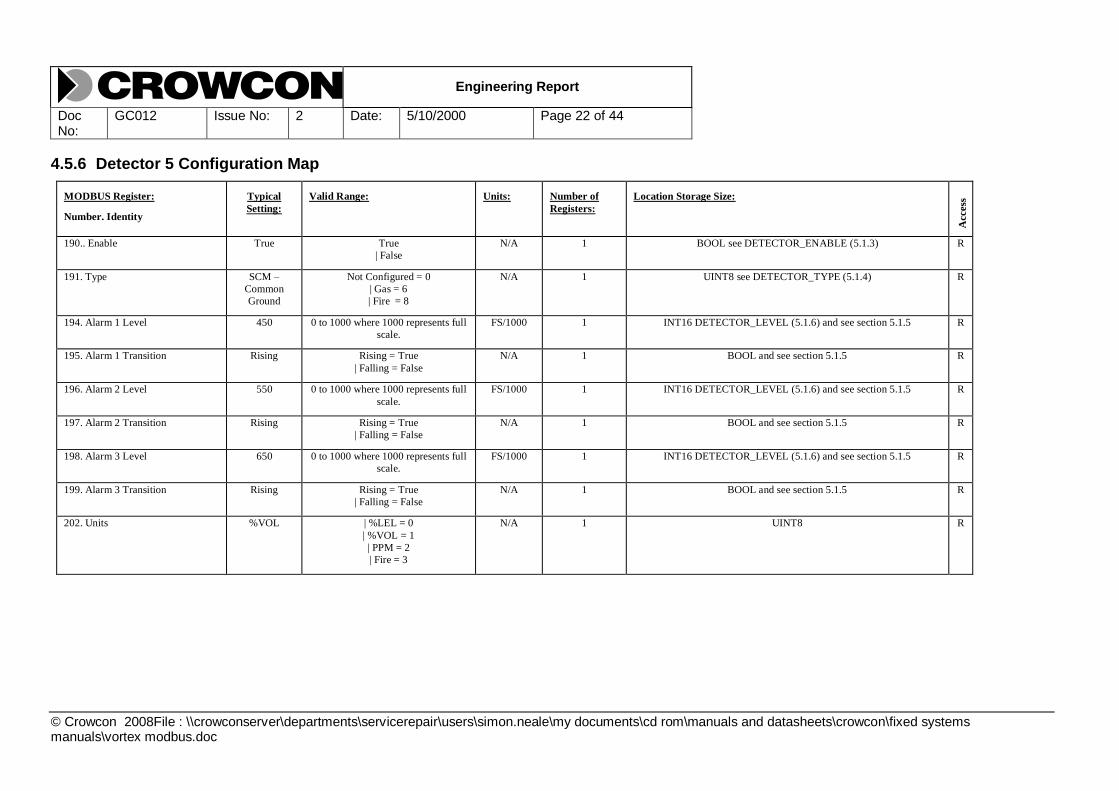
4.5.6 Detector 5 Configuration Map
MODBUS Register:
Number. Identity
Typical
Setting:
Valid Range: Units: Number of
Registers:
Location Storage Size:
Access
190.. Enable True True
| False
N/A 1 BOOL see DETECTOR_ENABLE (5.1.3) R
191. Type SCM –
Common
Ground
Not Configured = 0
| Gas = 6
| Fire = 8
N/A 1 UINT8 see DETECTOR_TYPE (5.1.4) R
194. Alarm 1 Level 450 0 to 1000 where 1000 represents full
scale.
FS/1000 1 INT16 DETECTOR_LEVEL (5.1.6) and see section 5.1.5 R
195. Alarm 1 Transition Rising Rising = True
| Falling = False
N/A 1 BOOL and see section 5.1.5 R
196. Alarm 2 Level 550 0 to 1000 where 1000 represents full
scale.
FS/1000 1 INT16 DETECTOR_LEVEL (5.1.6) and see section 5.1.5 R
197. Alarm 2 Transition Rising Rising = True
| Falling = False
N/A 1 BOOL and see section 5.1.5 R
198. Alarm 3 Level 650 0 to 1000 where 1000 represents full
scale.
FS/1000 1 INT16 DETECTOR_LEVEL (5.1.6) and see section 5.1.5 R
199. Alarm 3 Transition Rising Rising = True
| Falling = False
N/A 1 BOOL and see section 5.1.5 R
202. Units %VOL | %LEL = 0
| %VOL = 1
| PPM = 2
| Fire = 3
N/A 1 UINT8 R

Engineering Report
Doc No:
GC012 Issue No: 2 Date: 5/10/2000 Page 23 of 44
© Crowcon 2008File : \\crowconserver\departments\servicerepair\users\simon.neale\my documents\cd rom\manuals and datasheets\crowcon\fixed systems manuals\vortex modbus.doc
MODBUS Register:
Number. Identity
Typical
Setting:
Valid Range: Units: Number of
Registers:
Location Storage Size:
Access
203. Range 0 to 10 | 0 to 1 = 9
| 0 to 2 = 10
| 0 to 2.5 = 11
| 0 to 5 = 12
| 0 to 10 = 13
| 0 to 20 = 14
| 0 to 25 = 15
| 0 to 50 = 16
| 0 to 100 = 17
| 0 to 200 = 18
| 0 to 250 = 19
| 0 to 500 = 20
| 0 to 1,000 = 21
| 0 to 2,000 = 22
| 0 to 2,500 = 23
| 0 to 5,000 = 24
| 0 to 10,000 = 25
N/A 1 UINT8 R
206. Identity “T 1BYP-
DCT”
ASCII characters N/A 4 String 8 R
Engineering Report
Doc No:
GC012 Issue No: 2 Date: 5/10/2000 Page 24 of 44
© Crowcon 2008File : \\crowconserver\departments\servicerepair\users\simon.neale\my documents\cd rom\manuals and datasheets\crowcon\fixed systems manuals\vortex modbus.doc
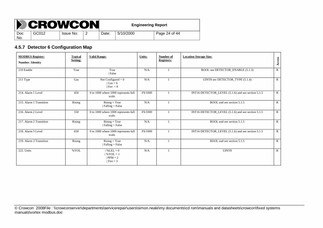
4.5.7 Detector 6 Configuration Map
MODBUS Register:
Number. Identity
Typical
Setting:
Valid Range: Units: Number of
Registers:
Location Storage Size:
Access
210 Enable True True
| False
N/A 1 BOOL see DETECTOR_ENABLE (5.1.3) R
211 Type Gas Not Configured = 0
| Gas = 6
| Fire = 8
N/A 1 UINT8 see DETECTOR_TYPE (5.1.4) R
214. Alarm 1 Level 450 0 to 1000 where 1000 represents full
scale.
FS/1000 1 INT16 DETECTOR_LEVEL (5.1.6) and see section 5.1.5 R
215. Alarm 1 Transition Rising Rising = True
| Falling = False
N/A 1 BOOL and see section 5.1.5 R
216. Alarm 2 Level 550 0 to 1000 where 1000 represents full
scale.
FS/1000 1 INT16 DETECTOR_LEVEL (5.1.6) and see section 5.1.5 R
217. Alarm 2 Transition Rising Rising = True
| Falling = False
N/A 1 BOOL and see section 5.1.5 R
218. Alarm 3 Level 650 0 to 1000 where 1000 represents full
scale.
FS/1000 1 INT16 DETECTOR_LEVEL (5.1.6) and see section 5.1.5 R
219. Alarm 3 Transition Rising Rising = True
| Falling = False
N/A 1 BOOL and see section 5.1.5 R
222. Units %VOL | %LEL = 0
| %VOL = 1
| PPM = 2
| Fire = 3
N/A 1 UINT8 R

Engineering Report
Doc No:
GC012 Issue No: 2 Date: 5/10/2000 Page 25 of 44
© Crowcon 2008File : \\crowconserver\departments\servicerepair\users\simon.neale\my documents\cd rom\manuals and datasheets\crowcon\fixed systems manuals\vortex modbus.doc
MODBUS Register:
Number. Identity
Typical
Setting:
Valid Range: Units: Number of
Registers:
Location Storage Size:
Access
223. Range 0 to 10 | 0 to 1 = 9
| 0 to 2 = 10
| 0 to 2.5 = 11
| 0 to 5 = 12
| 0 to 10 = 13
| 0 to 20 = 14
| 0 to 25 = 15
| 0 to 50 = 16
| 0 to 100 = 17
| 0 to 200 = 18
| 0 to 250 = 19
| 0 to 500 = 20
| 0 to 1,000 = 21
| 0 to 2,000 = 22
| 0 to 2,500 = 23
| 0 to 5,000 = 24
| 0 to 10,000 = 25
N/A 1 UINT8 R
226. Identity “T 1BYP-
DCT”
ASCII characters N/A 4 String 8 R

Engineering Report
Doc No:
GC012 Issue No: 2 Date: 5/10/2000 Page 26 of 44
© Crowcon 2008File : \\crowconserver\departments\servicerepair\users\simon.neale\my documents\cd rom\manuals and datasheets\crowcon\fixed systems manuals\vortex modbus.doc
4.5.8 Detector 7 Configuration Map
MODBUS Register:
Number. Identity
Typical
Setting:
Valid Range: Units: Number of
Registers:
Location Storage Size:
Access
230.. Enable True True
| False
N/A 1 BOOL see DETECTOR_ENABLE (5.1.3) R
231. Type Gas Not Configured = 0
| Gas = 6
| Fire = 8
N/A 1 UINT8 see DETECTOR_TYPE (5.1.4) R
234. Alarm 1 Level 450 0 to 1000 where 1000 represents full
scale.
FS/1000 1 INT16 DETECTOR_LEVEL (5.1.6) and see section 5.1.5 R
235. Alarm 1 Transition Rising Rising = True
| Falling = False
N/A 1 BOOL and see section 5.1.5 R
236. Alarm 2 Level 550 0 to 1000 where 1000 represents full
scale.
FS/1000 1 INT16 DETECTOR_LEVEL (5.1.6) and see section 5.1.5 R
237. Alarm 2 Transition Rising Rising = True
| Falling = False
N/A 1 BOOL and see section 5.1.5 R
238. Alarm 3 Level 650 0 to 1000 where 1000 represents full
scale.
FS/1000 1 INT16 DETECTOR_LEVEL (5.1.6) and see section 5.1.5 R
239. Alarm 3 Transition Rising Rising = True
| Falling = False
N/A 1 BOOL and see section 5.1.5 R
242. Units %VOL | %LEL = 0
| %VOL = 1
| PPM = 2
| Fire = 3
N/A 1 UINT8 R

Engineering Report
Doc No:
GC012 Issue No: 2 Date: 5/10/2000 Page 27 of 44
© Crowcon 2008File : \\crowconserver\departments\servicerepair\users\simon.neale\my documents\cd rom\manuals and datasheets\crowcon\fixed systems manuals\vortex modbus.doc
MODBUS Register:
Number. Identity
Typical
Setting:
Valid Range: Units: Number of
Registers:
Location Storage Size:
Access
243. Range 0 to 10 | 0 to 1 = 9
| 0 to 2 = 10
| 0 to 2.5 = 11
| 0 to 5 = 12
| 0 to 10 = 13
| 0 to 20 = 14
| 0 to 25 = 15
| 0 to 50 = 16
| 0 to 100 = 17
| 0 to 200 = 18
| 0 to 250 = 19
| 0 to 500 = 20
| 0 to 1,000 = 21
| 0 to 2,000 = 22
| 0 to 2,500 = 23
| 0 to 5,000 = 24
| 0 to 10,000 = 25
N/A 1 UINT8 R
246. Identity “T 1BYP-
DCT”
ASCII characters N/A 4 String 8 R

Engineering Report
Doc No:
GC012 Issue No: 2 Date: 5/10/2000 Page 28 of 44
© Crowcon 2008File : \\crowconserver\departments\servicerepair\users\simon.neale\my documents\cd rom\manuals and datasheets\crowcon\fixed systems manuals\vortex modbus.doc
4.5.9 Detector 8 Configuration Map
MODBUS Register:
Number. Identity
Typical
Setting:
Valid Range: Units: Number of
Registers:
Location Storage Size:
Access
250.. Enable True True
| False
N/A 1 BOOL see DETECTOR_ENABLE (5.1.3) R
251. Type Gas Not Configured = 0
| Gas = 6
| Fire = 8
N/A 1 UINT8 see DETECTOR_TYPE (5.1.4) R
254. Alarm 1 Level 450 0 to 1000 where 1000 represents full
scale.
FS/1000 1 INT16 DETECTOR_LEVEL (5.1.6)
and see section 5.1.5
R
255. Alarm 1 Transition Rising Rising = True
| Falling = False
N/A 1 BOOL
and see section 5.1.5
R
256. Alarm 2 Level 550 0 to 1000 where 1000 represents full
scale.
FS/1000 1 INT16 DETECTOR_LEVEL (5.1.6)
and see section 5.1.5
R
257. Alarm 2 Transition Rising Rising = True
| Falling = False
N/A 1 BOOL
and see section 5.1.5
R
258. Alarm 3 Level 650 0 to 1000 where 1000 represents full
scale.
FS/1000 1 INT16 DETECTOR_LEVEL (5.1.6)
and see section 5.1.5
R
259. Alarm 3 Transition Rising Rising = True
| Falling = False
N/A 1 BOOL
and see section 5.1.5
R
262. Units %VOL | %LEL = 0
| %VOL = 1
| PPM = 2
| Fire = 3
N/A 1 UINT8 R

Engineering Report
Doc No:
GC012 Issue No: 2 Date: 5/10/2000 Page 29 of 44
© Crowcon 2008File : \\crowconserver\departments\servicerepair\users\simon.neale\my documents\cd rom\manuals and datasheets\crowcon\fixed systems manuals\vortex modbus.doc
MODBUS Register:
Number. Identity
Typical
Setting:
Valid Range: Units: Number of
Registers:
Location Storage Size:
Access
263. Range 0 to 10 | 0 to 1 = 9
| 0 to 2 = 10
| 0 to 2.5 = 11
| 0 to 5 = 12
| 0 to 10 = 13
| 0 to 20 = 14
| 0 to 25 = 15
| 0 to 50 = 16
| 0 to 100 = 17
| 0 to 200 = 18
| 0 to 250 = 19
| 0 to 500 = 20
| 0 to 1,000 = 21
| 0 to 2,000 = 22
| 0 to 2,500 = 23
| 0 to 5,000 = 24
| 0 to 10,000 = 25
N/A 1 UINT8 R
266. Identity “T 1BYP-
DCT”
ASCII characters N/A 4 String 8 R

Engineering Report
Doc No:
GC012 Issue No: 2 Date: 5/10/2000 Page 30 of 44
© Crowcon 2008File : \\crowconserver\departments\servicerepair\users\simon.neale\my documents\cd rom\manuals and datasheets\crowcon\fixed systems manuals\vortex modbus.doc
4.5.10 Detector 9 Configuration Map
MODBUS Register:
Number. Identity
Typical
Setting:
Valid Range: Units: Number of
Registers:
Location Storage Size:
Access
270.. Enable True True
| False
N/A 1 BOOL see DETECTOR_ENABLE (5.1.3) R
271. Type Gas Not Configured = 0
| Gas = 6
| Fire = 8
N/A 1 UINT8 see DETECTOR_TYPE (5.1.4) R
274. Alarm 1 Level 450 0 to 1000 where 1000 represents full
scale.
FS/1000 1 INT16 DETECTOR_LEVEL (5.1.6) and see section 5.1.5 R
275. Alarm 1 Transition Rising Rising = True
| Falling = False
N/A 1 BOOL and see section 5.1.5 R
276. Alarm 2 Level 550 0 to 1000 where 1000 represents full
scale.
FS/1000 1 INT16 DETECTOR_LEVEL (5.1.6) and see section 5.1.5 R
277. Alarm 2 Transition Rising Rising = True
| Falling = False
N/A 1 BOOL and see section 5.1.5 R
278. Alarm 3 Level 650 0 to 1000 where 1000 represents full
scale.
FS/1000 1 INT16 DETECTOR_LEVEL (5.1.6) and see section 5.1.5 R
279. Alarm 3 Transition Rising Rising = True
| Falling = False
N/A 1 BOOL and see section 5.1.5 R
282. Units %VOL | %LEL = 0
| %VOL = 1
| PPM = 2
| Fire = 3
N/A 1 UINT8 R

Engineering Report
Doc No:
GC012 Issue No: 2 Date: 5/10/2000 Page 31 of 44
© Crowcon 2008File : \\crowconserver\departments\servicerepair\users\simon.neale\my documents\cd rom\manuals and datasheets\crowcon\fixed systems manuals\vortex modbus.doc
MODBUS Register:
Number. Identity
Typical
Setting:
Valid Range: Units: Number of
Registers:
Location Storage Size:
Access
283. Range 0 to 10 | 0 to 1 = 9
| 0 to 2 = 10
| 0 to 2.5 = 11
| 0 to 5 = 12
| 0 to 10 = 13
| 0 to 20 = 14
| 0 to 25 = 15
| 0 to 50 = 16
| 0 to 100 = 17
| 0 to 200 = 18
| 0 to 250 = 19
| 0 to 500 = 20
| 0 to 1,000 = 21
| 0 to 2,000 = 22
| 0 to 2,500 = 23
| 0 to 5,000 = 24
| 0 to 10,000 = 25
N/A 1 UINT8 R
286. Identity “T 1BYP-
DCT”
ASCII characters N/A 4 String 8 R
Engineering Report
Doc No:
GC012 Issue No: 2 Date: 5/10/2000 Page 32 of 44
© Crowcon 2008File : \\crowconserver\departments\servicerepair\users\simon.neale\my documents\cd rom\manuals and datasheets\crowcon\fixed systems manuals\vortex modbus.doc
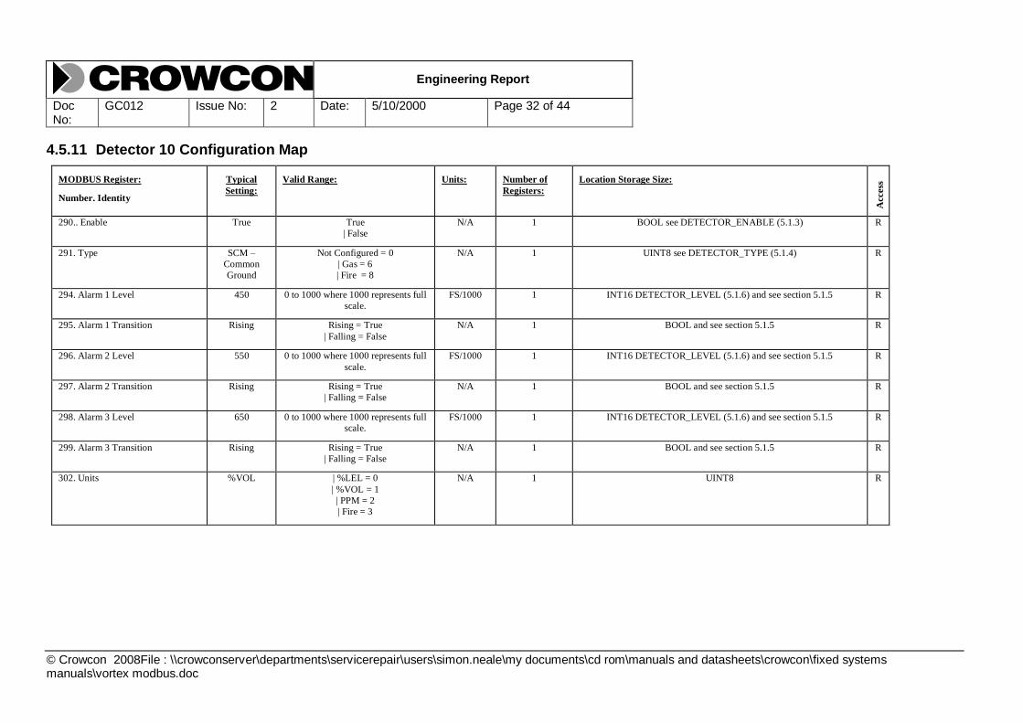
4.5.11 Detector 10 Configuration Map
MODBUS Register:
Number. Identity
Typical
Setting:
Valid Range: Units: Number of
Registers:
Location Storage Size:
Access
290.. Enable True True
| False
N/A 1 BOOL see DETECTOR_ENABLE (5.1.3) R
291. Type SCM –
Common
Ground
Not Configured = 0
| Gas = 6
| Fire = 8
N/A 1 UINT8 see DETECTOR_TYPE (5.1.4) R
294. Alarm 1 Level 450 0 to 1000 where 1000 represents full
scale.
FS/1000 1 INT16 DETECTOR_LEVEL (5.1.6) and see section 5.1.5 R
295. Alarm 1 Transition Rising Rising = True
| Falling = False
N/A 1 BOOL and see section 5.1.5 R
296. Alarm 2 Level 550 0 to 1000 where 1000 represents full
scale.
FS/1000 1 INT16 DETECTOR_LEVEL (5.1.6) and see section 5.1.5 R
297. Alarm 2 Transition Rising Rising = True
| Falling = False
N/A 1 BOOL and see section 5.1.5 R
298. Alarm 3 Level 650 0 to 1000 where 1000 represents full
scale.
FS/1000 1 INT16 DETECTOR_LEVEL (5.1.6) and see section 5.1.5 R
299. Alarm 3 Transition Rising Rising = True
| Falling = False
N/A 1 BOOL and see section 5.1.5 R
302. Units %VOL | %LEL = 0
| %VOL = 1
| PPM = 2
| Fire = 3
N/A 1 UINT8 R

Engineering Report
Doc No:
GC012 Issue No: 2 Date: 5/10/2000 Page 33 of 44
© Crowcon 2008File : \\crowconserver\departments\servicerepair\users\simon.neale\my documents\cd rom\manuals and datasheets\crowcon\fixed systems manuals\vortex modbus.doc
MODBUS Register:
Number. Identity
Typical
Setting:
Valid Range: Units: Number of
Registers:
Location Storage Size:
Access
303. Range 0 to 10 | 0 to 1 = 9
| 0 to 2 = 10
| 0 to 2.5 = 11
| 0 to 5 = 12
| 0 to 10 = 13
| 0 to 20 = 14
| 0 to 25 = 15
| 0 to 50 = 16
| 0 to 100 = 17
| 0 to 200 = 18
| 0 to 250 = 19
| 0 to 500 = 20
| 0 to 1,000 = 21
| 0 to 2,000 = 22
| 0 to 2,500 = 23
| 0 to 5,000 = 24
| 0 to 10,000 = 25
N/A 1 UINT8 R
306. Identity “T 1BYP-
DCT”
ASCII characters N/A 4 String 8 R

Engineering Report
Doc No:
GC012 Issue No: 2 Date: 5/10/2000 Page 34 of 44
© Crowcon 2008File : \\crowconserver\departments\servicerepair\users\simon.neale\my documents\cd rom\manuals and datasheets\crowcon\fixed systems manuals\vortex modbus.doc
4.5.12 Detector 11 Configuration Map
MODBUS Register:
Number. Identity
Typical
Setting:
Valid Range: Units: Number of
Registers:
Location Storage Size:
Access
310. Enable True True
| False
N/A 1 BOOL see DETECTOR_ENABLE (5.1.3) R
311. Type SCM –
Common
Ground
Not Configured = 0
| Gas = 6
| Fire = 8
N/A 1 UINT8 see DETECTOR_TYPE (5.1.4) R
314. Alarm 1 Level 450 0 to 1000 where 1000 represents full
scale.
FS/1000 1 INT16 DETECTOR_LEVEL (5.1.6)
and see section 5.1.5
R
315. Alarm 1 Transition Rising Rising = True
| Falling = False
N/A 1 BOOL
and see section 5.1.5
R
316. Alarm 2 Level 550 0 to 1000 where 1000 represents full
scale.
FS/1000 1 INT16 DETECTOR_LEVEL (5.1.6)
and see section 5.1.5
R
317. Alarm 2 Transition Rising Rising = True
| Falling = False
N/A 1 BOOL
and see section 5.1.5
R
318. Alarm 3 Level 650 0 to 1000 where 1000 represents full
scale.
FS/1000 1 INT16 DETECTOR_LEVEL (5.1.6)
and see section 5.1.5
R
319. Alarm 3 Transition Rising Rising = True
| Falling = False
N/A 1 BOOL
and see section 5.1.5
R
322. Units %VOL | %LEL = 0
| %VOL = 1
| PPM = 2
| Fire = 3
N/A 1 UINT8 R

Engineering Report
Doc No:
GC012 Issue No: 2 Date: 5/10/2000 Page 35 of 44
© Crowcon 2008File : \\crowconserver\departments\servicerepair\users\simon.neale\my documents\cd rom\manuals and datasheets\crowcon\fixed systems manuals\vortex modbus.doc
MODBUS Register:
Number. Identity
Typical
Setting:
Valid Range: Units: Number of
Registers:
Location Storage Size:
Access
323. Range 0 to 10 | 0 to 1 = 9
| 0 to 2 = 10
| 0 to 2.5 = 11
| 0 to 5 = 12
| 0 to 10 = 13
| 0 to 20 = 14
| 0 to 25 = 15
| 0 to 50 = 16
| 0 to 100 = 17
| 0 to 200 = 18
| 0 to 250 = 19
| 0 to 500 = 20
| 0 to 1,000 = 21
| 0 to 2,000 = 22
| 0 to 2,500 = 23
| 0 to 5,000 = 24
| 0 to 10,000 = 25
N/A 1 UINT8 R
326. Identity “T 1BYP-
DCT”
ASCII characters N/A 4 String 8 R

Engineering Report
Doc No:
GC012 Issue No: 2 Date: 5/10/2000 Page 36 of 44
© Crowcon 2008File : \\crowconserver\departments\servicerepair\users\simon.neale\my documents\cd rom\manuals and datasheets\crowcon\fixed systems manuals\vortex modbus.doc
4.5.13 Detector 12 Configuration Map
MODBUS Register:
Number. Identity
Typical
Setting:
Valid Range: Units: Number of
Registers:
Location Storage Size:
Access
330. Enable True True
| False
N/A 1 BOOL see DETECTOR_ENABLE (5.1.3) R
331. Type Gas Not Configured = 0
| Gas = 6
| Fire = 8
N/A 1 UINT8 see DETECTOR_TYPE (5.1.4) R
334. Alarm 1 Level 450 0 to 1000 where 1000 represents full
scale.
FS/1000 1 INT16 DETECTOR_LEVEL (5.1.6) and see section 5.1.5 R
335. Alarm 1 Transition Rising Rising = True
| Falling = False
N/A 1 BOOL and see section 5.1.5 R
336. Alarm 2 Level 550 0 to 1000 where 1000 represents full
scale.
FS/1000 1 INT16 DETECTOR_LEVEL (5.1.6) and see section 5.1.5 R
337. Alarm 2 Transition Rising Rising = True
| Falling = False
N/A 1 BOOL and see section 5.1.5 R
338. Alarm 3 Level 650 0 to 1000 where 1000 represents full
scale.
FS/1000 1 INT16 DETECTOR_LEVEL (5.1.6) and see section 5.1.5 R
339. Alarm 3 Transition Rising Rising = True
| Falling = False
N/A 1 BOOL and see section 5.1.5 R
342. Units %VOL | %LEL = 0
| %VOL = 1
| PPM = 2
| Fire = 3
N/A 1 UINT8 R
Engineering Report
Doc No:
GC012 Issue No: 2 Date: 5/10/2000 Page 37 of 44
© Crowcon 2008File : \\crowconserver\departments\servicerepair\users\simon.neale\my documents\cd rom\manuals and datasheets\crowcon\fixed systems manuals\vortex modbus.doc
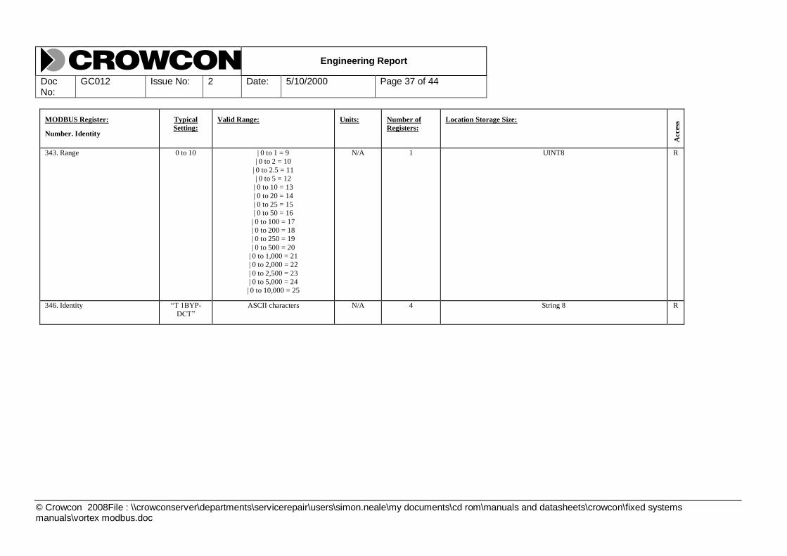
MODBUS Register:
Number. Identity
Typical
Setting:
Valid Range: Units: Number of
Registers:
Location Storage Size:
Access
343. Range 0 to 10 | 0 to 1 = 9
| 0 to 2 = 10
| 0 to 2.5 = 11
| 0 to 5 = 12
| 0 to 10 = 13
| 0 to 20 = 14
| 0 to 25 = 15
| 0 to 50 = 16
| 0 to 100 = 17
| 0 to 200 = 18
| 0 to 250 = 19
| 0 to 500 = 20
| 0 to 1,000 = 21
| 0 to 2,000 = 22
| 0 to 2,500 = 23
| 0 to 5,000 = 24
| 0 to 10,000 = 25
N/A 1 UINT8 R
346. Identity “T 1BYP-
DCT”
ASCII characters N/A 4 String 8 R

Engineering Report
Doc No:
GC012 Issue No: 2 Date: 5/10/2000 Page 38 of 44
© Crowcon 2008File : \\crowconserver\departments\servicerepair\users\simon.neale\my documents\cd rom\manuals and datasheets\crowcon\fixed systems manuals\vortex modbus.doc
4.5.14 Detector 1 Normal Map
MODBUS Register:
Number. Identity
Typical
Setting:
Valid Range: Units: Number of
Registers:
Location Storage Size:
Access
3000. Detector Level 450 0 to 1000 FS/1000 1 INT16 DETECTOR_LEVEL (5.1.6) R
3001. Detector Status N/A N/A N/A 1 UINT16 DETECTOR_STATUS(5.1.7) R
3004. Inhibit True Inhibited = True
|Not Inhibited = False
N/A 1 BOOL DETECTOR INHIBIT (5.1.8) W
4.5.15 Detector 2 Normal Map
MODBUS Register:
Number. Identity
Typical
Setting:
Valid Range: Units: Number of
Registers:
Location Storage Size:
Access
3010. Detector Level 450 0 to 1000 FS/1000 1 INT16 DETECTOR_LEVEL (5.1.6) R
3011. Detector Status N/A N/A N/A 1 UINT16 DETECTOR_STATUS(5.1.7) R
3014. Inhibit True Inhibited = True
|Not Inhibited = False
N/A 1 BOOL DETECTOR INHIBIT (5.1.8) W
4.5.16 Detector 3 Normal Map
MODBUS Register:
Number. Identity
Typical
Setting:
Valid Range: Units: Number of
Registers:
Location Storage Size:
Access
Rig
hts
3020. Detector Level 450 0 to 1000 FS/1000 1 INT16 DETECTOR_LEVEL (5.1.6) R
3021. Detector Status N/A N/A N/A 1 UINT16 DETECTOR_STATUS(5.1.7) R
3024. Inhibit True Inhibited = True
|Not Inhibited = False
N/A 1 BOOL DETECTOR INHIBIT (5.1.8) W

Engineering Report
Doc No:
GC012 Issue No: 2 Date: 5/10/2000 Page 39 of 44
© Crowcon 2008File : \\crowconserver\departments\servicerepair\users\simon.neale\my documents\cd rom\manuals and datasheets\crowcon\fixed systems manuals\vortex modbus.doc
4.5.17 Detector 4 Normal Map
MODBUS Register:
Number. Identity
Typical
Setting:
Valid Range: Units: Number of
Registers:
Location Storage Size:
Access
3030. Detector Level 450 0 to 1000 FS/1000 1 INT16 DETECTOR_LEVEL (5.1.6) R
3031. Detector Status N/A N/A N/A 1 UINT16 DETECTOR_STATUS(5.1.7) R
3034. Inhibit True Inhibited = True
|Not Inhibited = False
N/A 1 BOOL DETECTOR INHIBIT (5.1.8) W
4.5.18 Detector 5 Normal Map
MODBUS Register:
Number. Identity
Typical
Setting:
Valid Range: Units: Number of
Registers:
Location Storage Size:
Access
3040. Detector Level 450 0 to 1000 FS/1000 1 INT16 DETECTOR_LEVEL (5.1.6) R
3041. Detector Status N/A N/A N/A 1 UINT16 DETECTOR_STATUS(5.1.7) R
3044. Inhibit True Inhibited = True
|Not Inhibited = False
N/A 1 BOOL DETECTOR INHIBIT (5.1.8) W
4.5.19 Detector 6 Normal Map
MODBUS Register:
Number. Identity
Typical
Setting:
Valid Range: Units: Number of
Registers:
Location Storage Size:
Access
3050. Detector Level 450 0 to 1000 FS/1000 1 INT16 DETECTOR_LEVEL (5.1.6) R
3051. Detector Status N/A N/A N/A 1 UINT16 DETECTOR_STATUS(5.1.7) R
3054. Inhibit True Inhibited = True
|Not Inhibited = False
N/A 1 BOOL DETECTOR INHIBIT (5.1.8) W

Engineering Report
Doc No:
GC012 Issue No: 2 Date: 5/10/2000 Page 40 of 44
© Crowcon 2008File : \\crowconserver\departments\servicerepair\users\simon.neale\my documents\cd rom\manuals and datasheets\crowcon\fixed systems manuals\vortex modbus.doc
4.5.20 Detector 7 Normal Map
MODBUS Register:
Number. Identity
Typical
Setting:
Valid Range: Units: Number of
Registers:
Location Storage Size:
Access
3060. Detector Level 450 0 to 1000 FS/1000 1 INT16 DETECTOR_LEVEL (5.1.6) R
3061. Detector Status N/A N/A N/A 1 UINT16 DETECTOR_STATUS(5.1.7) R
3064. Inhibit True Inhibited = True
|Not Inhibited = False
N/A 1 BOOL DETECTOR INHIBIT (5.1.8) W
4.5.21 Detector 8 Normal Map
MODBUS Register:
Number. Identity
Typical
Setting:
Valid Range: Units: Number of
Registers:
Location Storage Size:
Access
3070. Detector Level 450 0 to 1000 FS/1000 1 INT16 DETECTOR_LEVEL (5.1.6) R
3071. Detector Status N/A N/A N/A 1 UINT16 DETECTOR_STATUS(5.1.7) R
3074. Inhibit True Inhibited = True
|Not Inhibited = False
N/A 1 BOOL DETECTOR INHIBIT (5.1.8) W
4.5.22 Detector 9 Normal Map
MODBUS Register:
Number. Identity
Typical
Setting:
Valid Range: Units: Number of
Registers:
Location Storage Size:
Access
3080. Detector Level 450 0 to 1000 FS/1000 1 INT16 DETECTOR_LEVEL (5.1.6) R
3081. Detector Status N/A N/A N/A 1 UINT16 DETECTOR_STATUS(5.1.7) R
3084. Inhibit True Inhibited = True
|Not Inhibited = False
N/A 1 BOOL DETECTOR INHIBIT (5.1.8) W
Engineering Report
Doc No:
GC012 Issue No: 2 Date: 5/10/2000 Page 41 of 44
© Crowcon 2008File : \\crowconserver\departments\servicerepair\users\simon.neale\my documents\cd rom\manuals and datasheets\crowcon\fixed systems manuals\vortex modbus.doc
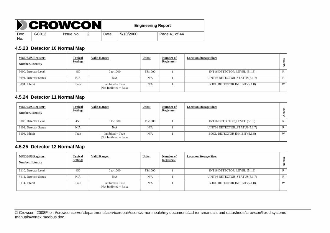
4.5.23 Detector 10 Normal Map
MODBUS Register:
Number. Identity
Typical
Setting:
Valid Range: Units: Number of
Registers:
Location Storage Size:
Access
3090. Detector Level 450 0 to 1000 FS/1000 1 INT16 DETECTOR_LEVEL (5.1.6) R
3091. Detector Status N/A N/A N/A 1 UINT16 DETECTOR_STATUS(5.1.7) R
3094. Inhibit True Inhibited = True
|Not Inhibited = False
N/A 1 BOOL DETECTOR INHIBIT (5.1.8) W
4.5.24 Detector 11 Normal Map
MODBUS Register:
Number. Identity
Typical
Setting:
Valid Range: Units: Number of
Registers:
Location Storage Size:
Access
3100. Detector Level 450 0 to 1000 FS/1000 1 INT16 DETECTOR_LEVEL (5.1.6) R
3101. Detector Status N/A N/A N/A 1 UINT16 DETECTOR_STATUS(5.1.7) R
3104. Inhibit True Inhibited = True
|Not Inhibited = False
N/A 1 BOOL DETECTOR INHIBIT (5.1.8) W
4.5.25 Detector 12 Normal Map
MODBUS Register:
Number. Identity
Typical
Setting:
Valid Range: Units: Number of
Registers:
Location Storage Size:
Access
3110. Detector Level 450 0 to 1000 FS/1000 1 INT16 DETECTOR_LEVEL (5.1.6) R
3111. Detector Status N/A N/A N/A 1 UINT16 DETECTOR_STATUS(5.1.7) R
3114. Inhibit True Inhibited = True
|Not Inhibited = False
N/A 1 BOOL DETECTOR INHIBIT (5.1.8) W

Engineering Report
Doc No:
GC012 Issue No: 2 Date: 5/10/2000 Page 42 of 44
© Crowcon 2008File : \\crowconserver\departments\servicerepair\users\simon.neale\my documents\cd rom\manuals and datasheets\crowcon\fixed systems manuals\vortex modbus.doc
5. Supplementary Definitions Supporting MODBUS Register Map
5.1 System Registers
5.1.1 SYSTEM_STATUS Type
This is a bit packed status word, which allows the MODBUS master to access to determine the state of the Vortex
system. The register is formatted as follows:-
BIT MEANING
0 Set to one if Vortex system is in channel test
1 Set to one if Vortex system is in jump hold
2 Set to one if Vortex system has a system fault.
3 Set to one if system fault is a battery fault.
4 Set to one if system fault is a FRAM data integrity
fault
5 Set to one if system fault is an internal I2C bus fault.
6 Set to one if system fault is a display access fault.
7 Set to one if system fault is a power monitor access
fault.
8 Set to one if system fault is an external I2C bus fault.
9 Set to one if system fault is a relay board fault.
10 to 15 Undefined – set to zero.
5.1.2 System Inhibits
System Fault Inhibit and System Sounder Inhibit prevent system faults or system sounder events from reaching the
relay outputs. This is used when the system is being maintained to prevent the triggering of external alarm equipment.
NOTE when using these inhibit registers there is no warning on the front panel so care must be exercised not to leave
an inhibit flag set unintentionally.

Engineering Report
Doc No:
GC012 Issue No: 2 Date: 5/10/2000 Page 43 of 44
© Crowcon 2008File : \\crowconserver\departments\servicerepair\users\simon.neale\my documents\cd rom\manuals and datasheets\crowcon\fixed systems manuals\vortex modbus.doc
Detector Registers
5.1.3 DETECTOR_ENABLE Type
Enabled detectors are scanned for alarm and fault levels on their inputs and participate in the setting of relays.
On the transition from enabled to disabled all the alarm and fault flags associated with a detector are cleared.
Disabled detectors are not scanned and do not generate faults or alarms, also they are not displayed on the front panel.
5.1.4 DETECTOR_TYPE
For Vortex the detector types are Gas and Fire or Not Configured. Not Configured types do not participate in the
system and all configuration data is considered invalid.
5.1.5 Detector Alarm Settings
NOTE : For gas detectors, each alarm may be individually set rising or falling.
NOTE : For fire detectors, all alarms will be set to „rising‟ and scaled such that a value of 1000 implies a current reading of 60 mA. Also for fire detectors, the meaning of each alarm level will be as follows
Alarm Level 1 Open Circuit Detection Level
Alarm Level 2 Alarm Level (i.e. „Fire‟)
Alarm Level 3 Short Circuit Detection Level
5.1.6 DETECTOR_LEVEL Type
Bit(s) Purpose
15-0 2‟s complement Detector Level
The nominal range, for gas level readings, is -100 to 1000, which
corresponds to –10% to 100% of Full Scale (set in the gas detector‟s configuration data).
The range, for fire detector readings, is -100 to 1000, where 1000
corresponds to 60mA.
The range for alarm thresholds which use the same data format is limited to
0 to 1000 (i.e. 0 to 100% Full Scale).
5.1.7 DETECTOR_STATUS Type
This shows the current status of the detector channel. A bit set to logic 1 indicates that the defined condition is present.
Bit(s) Purpose
15-10 Unused
9 Detector Inhibit from controller (inhibit button pushed or inhibited from comms link).
8 Detector I2C fault
7 High End Fault
6 Low End Fault
5 Detector level interpreted as High Info
4 Detector level interpreted as Low Info
3 Detector level interpreted as Inhibit

Engineering Report
Doc No:
GC012 Issue No: 2 Date: 5/10/2000 Page 44 of 44
© Crowcon 2008File : \\crowconserver\departments\servicerepair\users\simon.neale\my documents\cd rom\manuals and datasheets\crowcon\fixed systems manuals\vortex modbus.doc
2 Alarm level 3 present
1 Alarm level 2 present
0 Alarm level 1 present
5.1.8 DETECTOR INHIBIT Type
“Detector Inhibit” can be set using these registers.
The “inhibit” lamp on the front panel will be lit if any of the 4 inputs are inhibited. Pressing the front panel button with
any input inhibited will remove the “inhibit”. Pressing the “inhibit” button with no inhibits present will inhibit all 4
channels (subject to them being configured and enabled).
The inhibit status of any input can be read from the detector status word see section 5.1.7.
NOTE that input inhibit states are NOT stored in NVM, thus are volatile.