volume 2 civil engineer disaster and attack preparations · by order of the secretary of the air...
TRANSCRIPT
BY ORDER OF THESECRETARY OF THE AIR FORCE
AIR FORCE PAMPHLET 10-219, VOLUME 2
9 JUNE 2008
Operations
CIVIL ENGINEER DISASTER ANDATTACK PREPARATIONS
ACCESSIBILITY: Publications and forms are available on the e-Publishing web site at http://www.e-publishing.af.mil for downloading or ordering.
RELEASABILITY: There are no releasability restrictions on this publication.
OPR: HQ AFCESA/CEXX Certified by: HQ USAF/A7CX(Colonel Donald L. Gleason)
Supersedes AFPAM10-219V2, 1 November 1996 Pages: 160
This volume provides information to help Air Force civil engineers prepare their installations and unitsfor disasters and attacks. It outlines standard civil engineer preparations and focuses on methods to protectlife and support and sustain installation and unit operations. This volume is not intended to providedetailed construction or other “how to” procedures, rather its purpose is to provide civil engineers with thebackground and actions necessary to save lives and reduce facility damage resulting from accidents,disasters, terrorism, and war. This publication applies to all Air Force active, Air National Guard (ANG),and Air Force Reserve Command Civil Engineer units. The pamphlet supports Air Force Instruction(AFI) 10-210, Prime Base Engineer Emergency Force (BEEF) Program, AFI 10-211, Civil EngineerContingency Response Planning, and AFI 10-2501, Air Force Emergency Management (EM) ProgramPlanning and Operation. Refer recommended changes and questions about this publication to the Officeof Primary Responsibility (OPR) using the AF IMT 847, Recommendation for Change of Publication;route AF IMTs 847 from the field through Major Command (MAJCOM) publications/forms managers.Ensure that all records created as a result of processes prescribed in this publication are maintained inaccordance with Air Force Manual (AFMAN) 33-363, Management of Records, and disposed of in accor-dance with Air Force Records Information Management System (AFRIMS) Records Disposition Sched-ule (RDS) located at https://afrims.amc.af.mil/rds_series.cfm. The use of the name or mark of anyspecific manufacturer, commercial product, commodity, or service in this publication does not implyendorsement by the Air Force. See Attachment 1 for a glossary of references and supporting information.
SUMMARY OF CHANGES
This document has been substantially revised and must be completely reviewed. Major changes include anew publication title, the addition of spill response considerations, base denial preparations, and new AFincident management terms. The following topic areas were deleted and are addressed in other publica-tions. Expedient erection and construction methods for soil berms and dikes are discussed in AFPAM10-219, Volume 7, Expedient Methods. Erection and construction methods for defensive fighting posi-tions and bunkers; camouflage and concealment techniques, and expedient hardening methods (such as

2 AFPAM10-219V2 9 JUNE 2008
revetments and obstacles) are addressed in Air Force Handbook (AFH) 10-222, Volume 14, Guide toFighting Positions, Obstacles, and Revetments.
Chapter 1— INTRODUCTION 8
1.1. General Information. .................................................................................................. 8
Figure 1.1. Installation Agencies Train Together on Emergency Preparations. ......................... 8
1.2. Overview. ................................................................................................................... 8
Chapter 2— STANDARD INSTALLATION PREPARATIONS 10
2.1. Introduction. ............................................................................................................... 10
2.2. Preparation Considerations. ....................................................................................... 10
Figure 2.1. Services Squadron Personnel Erect Modular Tent in Iraq. ....................................... 11
2.3. Choosing Solutions and Determining Priorities. ....................................................... 11
Table 2.1. Factors to Consider When Choosing Solutions and Determining Priorities. ........... 11
2.4. An Approach to Preparing Your Installation. ............................................................ 12
Figure 2.2. Keep Response Teams’ Skills Sharp Through Realistic Practice. ............................ 13
2.5. Standard Preparation Actions. ................................................................................... 14
Table 2.2. Vulnerability Reduction/Resource Protection Preparations. .................................... 14
Table 2.3. Communications-Computer Systems Preparations. ................................................. 16
Table 2.4. Emergency and Backup Utilities Preparations. ........................................................ 16
Table 2.5. Environmental Hazard Reduction Preparations. ....................................................... 16
Table 2.6. Utility System Isolation Preparations. ...................................................................... 17
Table 2.7. CE Support To Others. .............................................................................................. 17
Table 2.8. Base Denial Preparations (Overseas Theater Task Only). ........................................ 18
Chapter 3— VULNERABILITY REDUCTION AND RESOURCE PROTECTION 19
3.1. Introduction. ............................................................................................................... 19
3.2. Shelters. ...................................................................................................................... 19
Figure 3.1. Temporary Shelters May Be Used for Extended Periods When Necessary. ............ 20
Table 3.1. Space Allocation Conditions. ................................................................................... 21
Figure 3.2. Required Ventilation to Control Temperature (Cubic Ft. Per Min. Per Person). ..... 23
Figure 3.3. Minimum Water Required. ....................................................................................... 23
Figure 3.4. Sheltered Vehicles and Equipment. .......................................................................... 26

AFPAM10-219V2 9 JUNE 2008 3
Figure 3.5. Engineers Build Aircraft Shelters from B-1 Steel Revetment Kits. ......................... 27
Figure 3.6. HESCO Barriers Provide Limited Shelter for Aircraft. ............................................ 27
Figure 3.7. Airmen Push Aircraft Into Hardened Aircraft Shelter. ............................................. 27
Figure 3.8. TAB VEE Permanent Aircraft Shelters Still in Widespread Use. ............................ 28
Figure 3.9. UAV Sits in a Bunker at a Forward Operating Location. ......................................... 28
3.3. Redundancy. .............................................................................................................. 28
3.4. Hardening. .................................................................................................................. 28
Table 3.2. Factors to Consider for Expedient Hardening. ......................................................... 29
Table 3.3. Design, Construction, and Special Considerations Matrix. ...................................... 32
Figure 3.10. Freestanding Berm. ................................................................................................... 34
Figure 3.11. Bermed Wall. ............................................................................................................ 35
Figure 3.12. Bermed Retaining Wall. ........................................................................................... 35
Figure 3.13. Fortifying Shelter with Sandbags. ............................................................................ 37
Figure 3.14. Configuration for Protecting a Building With Concrete Modular Revetments. ....... 38
Figure 3.15. Concrete Modular Revetment Protects Key Equipment. .......................................... 38
Figure 3.16. Double Wall Bin Revetment. .................................................................................... 39
Figure 3.17. Engineers Erecting Steel Bin Revetment Kits. ......................................................... 40
Figure 3.18. Engineers Fill HESCO Barrier Revetment With Soil. .............................................. 40
Figure 3.19. Sand Grid Form. ....................................................................................................... 41
Figure 3.20. Gravel-Filled Sand Grid. ........................................................................................... 42
Figure 3.21. Predetonation Screen. ............................................................................................... 42
Table 3.4. Hardening References. .............................................................................................. 43
3.5. Dispersal. ................................................................................................................... 43
Figure 3.22. Dispersal Planning and Preparation Flowchart. ........................................................ 44
Figure 3.23. Dispersed Base Layout. ............................................................................................ 46
Figure 3.24. Dispersing Key Equipment Behind Buildings. ......................................................... 47
Figure 3.25. Airmen Use Sandbags to Enhance Shelter Survivability. ......................................... 51
Table 3.5. Dispersal References. ................................................................................................ 54
3.6. Antiterrorism Measures. ............................................................................................ 54
Table 3.6. Antiterrorism References. ......................................................................................... 54

4 AFPAM10-219V2 9 JUNE 2008
3.7. CBRN Passive Defensive Measures. ......................................................................... 54
Figure 3.26. Effective Decontamination Prevents Casualties. ...................................................... 56
Table 3.7. Typical Installation CBRN Passive Defensive Measures. ........................................ 57
3.8. Base Evacuation. ........................................................................................................ 58
Chapter 4— COMMUNICATIONS SYSTEMS 60
4.1. Introduction. ............................................................................................................... 60
4.2. Communications Systems. ......................................................................................... 60
4.3. Installation Notification and Warning System (INWS). ............................................ 61
Table 4.1. INWS Features. ......................................................................................................... 62
Figure 4.1. Engineers Install Giant Voice System at Deployed Location. .................................. 63
4.4. Other Command and Control Preparations. ............................................................... 63
Figure 4.2. Typical ESF Work Station Arrangement. ................................................................. 64
Table 4.2. Map Types and Scale. ............................................................................................... 64
Table 4.3. Incident Status Displays. ........................................................................................... 65
Figure 4.3. Civil Engineer DCC Facility. .................................................................................... 65
Table 4.4. Support Plans and Their Purpose. ............................................................................. 66
Table 4.5. DCC Status Charts. ................................................................................................... 67
Table 4.6. DCC Communication Methods. ............................................................................... 68
Table 4.7. Force Protection Conditions (FPCONs). .................................................................. 69
4.5. Summary. ................................................................................................................... 70
Table 4.8. C2 and Communications Preparations References. .................................................. 70
Chapter 5— ISOLATION, BACKUP, AND PROTECTION OF UTILITIES 71
5.1. Introduction. ............................................................................................................... 71
5.2. Learning the Systems. ................................................................................................ 71
Figure 5.1. Typical Demand (or Discharge). .............................................................................. 72
5.3. Assessing Vulnerabilities. .......................................................................................... 72
5.4. Determining Critical Requirements. .......................................................................... 73
5.5. Electrical System Preparations. ................................................................................. 74
Figure 5.2. Power Plant Generator. ............................................................................................. 75
Figure 5.3. Example of Distribution System Parts. ..................................................................... 77

AFPAM10-219V2 9 JUNE 2008 5
5.6. Water System Preparations. ....................................................................................... 78
Figure 5.4. Deep Well Water Supply. ......................................................................................... 80
Figure 5.5. Water Supply Sources. .............................................................................................. 80
Figure 5.6. Typical Water Distribution System Pattern. ............................................................. 81
Table 5.1. Elements of Water Distribution System. .................................................................. 81
5.7. Central Heating System Preparations. ....................................................................... 84
Figure 5.7. Central Heating System. ........................................................................................... 84
5.8. Gas System Preparations. .......................................................................................... 86
Table 5.2. Gas Pressure Ranges. ................................................................................................ 86
5.9. Liquid Fuel System Preparations. .............................................................................. 88
Figure 5.8. Typical POL System. ................................................................................................ 89
5.10. Sanitary Sewage Collection and Disposal System Preparations. .............................. 90
Figure 5.9. Sewage Treatment System. ....................................................................................... 90
5.11. Airfield Lighting System. .......................................................................................... 92
Figure 5.10. Lighted Runway. ....................................................................................................... 92
Figure 5.11. Bean Bag Light. ........................................................................................................ 93
5.12. Demand Reduction. ................................................................................................... 93
5.13. Summary. ................................................................................................................... 94
Table 5.3. Utility Isolation, Backup, and Physical Protection References. ............................... 94
Chapter 6— BEDDOWN OPERATIONS 95
6.1. Introduction. ............................................................................................................... 95
Figure 6.1. Beddown of FEMA Personnel in New Orleans During Hurricane Katrina. ............. 95
6.2. Beddown Concepts. ................................................................................................... 95
Figure 6.2. Air and Space Expeditionary Task Force (AETF) Force Modules. ......................... 97
Figure 6.3. Sandbagging Overhead Cover of a Bare Base Shelter. ............................................ 97
Table 6.1. Standards of Construction. ........................................................................................ 99
6.3. Beddown Facilities and Utilities. ............................................................................... 100
Figure 6.4. Engineers Lay Out Power Cables at Forward Operating Location. ......................... 106
Figure 6.5. Sheltered Generators. ................................................................................................ 107
Figure 6.6. 600-GPH Reverse Osmosis Water Purification Unit (ROWPU). ............................. 108
6 AFPAM10-219V2 9 JUNE 2008
Figure 6.7. 1500-GPH Reverse Osmosis Water Purification Unit (ROWPU). ........................... 108
Figure 6.8. Water Distribution Point. .......................................................................................... 109
Table 6.2. Planning Factors for Showers and Lavatories. ......................................................... 110
Table 6.3. Expedient Waste Disposal Methods. ........................................................................ 111
6.4. Summary. ................................................................................................................... 113
Table 6.4. Beddown References. ............................................................................................... 113
Chapter 7— ENVIRONMENTAL HAZARDS 114
7.1. Introduction. ............................................................................................................... 114
7.2. HAZMAT Response Planning. .................................................................................. 114
Table 7.1. Hazards Analysis Process. ........................................................................................ 114
7.3. HAZMAT Capability Assessment. ............................................................................ 115
7.4. HAZMAT Spill Response Considerations. ............................................................... 115
Figure 7.1. Firefighters Douse Fire Caused by Accidental Fuel Spill. ....................................... 116
Table 7.2. Spill Team Members. ................................................................................................ 116
7.5. Summary. ................................................................................................................... 117
Table 7.3. HAZMAT Planning and Preparation References. .................................................... 117
Chapter 8— SUPPORT TO AND FROM OTHERS 118
8.1. Introduction. ............................................................................................................... 118
8.2. Support to Civil Engineers. ........................................................................................ 118
Table 8.1. Support to Civil Engineers. ....................................................................................... 118
8.3. Civil Engineer Support to Others. .............................................................................. 119
Figure 8.1. Preparations Include Procedures for Recording and Reporting Casualties. ............. 119
Figure 8.2. Command Centers, Specialized Teams, and Individuals Utilize Maps. ................... 120
8.4. Summary. ................................................................................................................... 120
Table 8.2. CE Support References. ............................................................................................ 121
Chapter 9— BASE DENIAL 122
9.1. Introduction. ............................................................................................................... 122
9.2. Base Denial Considerations. ...................................................................................... 122
Figure 9.1. Total Facility Denial. ................................................................................................ 123
9.3. Conventional Base Denial Methods. ......................................................................... 123

AFPAM10-219V2 9 JUNE 2008 7
Figure 9.2. Asset Evacuation. ...................................................................................................... 124
Figure 9.3. Remove Like Components to Prevent Cannibalization. ........................................... 125
Figure 9.4. Using Water to Ruin Bags of Cement. ..................................................................... 126
Figure 9.5. Caustic Fluid Destruction. ........................................................................................ 127
Figure 9.6. Typical Obstacles. ..................................................................................................... 127
Figure 9.7. Barbed Wire Entanglement. ...................................................................................... 128
9.4. Base Denial Responsibilities and Techniques. .......................................................... 128
9.5. Withdrawal and Evacuation. ...................................................................................... 131
9.6. Summary. ................................................................................................................... 132
Chapter 10— INFORMATION COLLECTION, RECORDS, AND FORMS. 133
10.1. Information Collections. ............................................................................................ 133
10.2. Records. ..................................................................................................................... 133
10.3. Forms (Adopted and Prescribed). .............................................................................. 133
Attachment 1— GLOSSARY OF REFERENCES AND SUPPORTING INFORMATION 134
Attachment 2— SAMPLE STATUS CHARTS 147
Attachment 3— HISTORICAL ENERGY DISRUPTIONS EXPERIENCE 151
Attachment 4— BASE COMPREHENSIVE PLAN MAP (AFI 32-7062) 154
Attachment 5— SAMPLE UTILITY SYSTEM APPENDIX—CE CONTINGENCY RESPONSE PLAN 157
8 AFPAM10-219V2 9 JUNE 2008
Chapter 1 INTRODUCTION
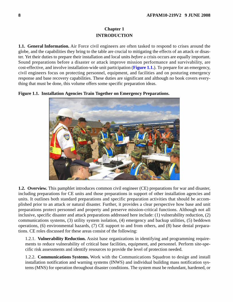
1.1. General Information. Air Force civil engineers are often tasked to respond to crises around theglobe, and the capabilities they bring to the table are crucial to mitigating the effects of an attack or disas-ter. Yet their duties to prepare their installation and local units before a crisis occurs are equally important.Sound preparations before a disaster or attack improve mission performance and survivability, arecost-effective, and involve installation-wide unit participation (Figure 1.1.). To prepare for an emergency,civil engineers focus on protecting personnel, equipment, and facilities and on posturing emergencyresponse and base recovery capabilities. These duties are significant and although no book covers every-thing that must be done, this volume offers some specific preparation ideas.
Figure 1.1. Installation Agencies Train Together on Emergency Preparations.
1.2. Overview. This pamphlet introduces common civil engineer (CE) preparations for war and disaster,including preparations for CE units and those preparations in support of other installation agencies andunits. It outlines both standard preparations and specific preparation activities that should be accom-plished prior to an attack or natural disaster. Further, it provides a clear perspective how base and unitpreparations protect personnel and property and preserve mission-critical functions. Although not allinclusive, specific disaster and attack preparations addressed here include: (1) vulnerability reduction, (2)communications systems, (3) utility system isolation, (4) emergency and backup utilities, (5) beddownoperations, (6) environmental hazards, (7) CE support to and from others, and (8) base denial prepara-tions. CE roles discussed for these areas consist of the following:
1.2.1. Vulnerability Reduction. Assist base organizations in identifying and programming require-ments to reduce vulnerability of critical base facilities, equipment, and personnel. Perform site-spe-cific risk assessments and identify resources to provide the level of protection needed.
1.2.2. Communications Systems. Work with the Communications Squadron to design and installinstallation notification and warning systems (INWS) and individual building mass notification sys-tems (MNS) for operation throughout disaster conditions. The system must be redundant, hardened, or

AFPAM10-219V2 9 JUNE 2008 9
splinter-protected and operate using both commercial and emergency power. Ensure the CE DamageControl Center (DCC), Fire Alarm Communications Center (FACC), and Mobile Emergency Opera-tions Center (MEOC) have survivable and interoperable communications among the primary andalternate Emergency Communications Center (ECC), Installation Control Center (ICC), EmergencyOperations Center (EOC), Security Forces (SF) desk, and Medical dispatch (if applicable). Also,establish manual communication procedures to collect damage assessment information during disrup-tions to installation communication and computer systems.
1.2.3. Utility System Isolation. Maintain accurate utility distribution system drawings within the CEDCC and FACC, showing the locations of all cutoff valves and switches. Periodically have the appro-priate personnel locate and operate these valves and switches to ensure they are operational and con-trol the desired systems. When possible, implement the GeoBase Mapping System to aid inidentifying and locating critical equipment or resources.
1.2.4. Emergency and Backup Utilities. Develop plans and identify resources required to promptlyreestablish utilities or provide backup systems for critical facilities before or immediately after anattack or disaster.
1.2.5. Beddown Operations. Provide expedient beddown support for incoming forces or disastervictims. Civil engineers erect, modify, or construct many of the facilities, including utilities that AirForce units need for military deployment and disaster relief. CE also provides on-site guidance andexpertise to other units to erect their own portable shelters and defensive measures.
1.2.6. Environmental Hazard Reduction. Provide trained personnel and available equipment andmaterials to help the Base Spill Response Team with containment, cleanup, and site restoration forhazardous substance spills.
1.2.7. CE Support To and From Others. Provide training, guidance, labor, equipment, maps, andexpertise as necessary. CE receives assistance with vehicles, fuels, and other logistics from supportagencies and units.
1.2.8. Base Denial. Plan appropriate denial methods, including item evacuation, selective componentremoval, destruction, and use of obstacles. Also prepare in advance a candidate list of select base sys-tems, equipment, and supplies for potential destruction should the commander direct base evacuationand denial action.

10 AFPAM10-219V2 9 JUNE 2008
Chapter 2
STANDARD INSTALLATION PREPARATIONS
2.1. Introduction. Smart disaster or attack preparations can be made at every installation—whether mainbases, collocated operating bases, bare bases, or remote sites. Many preparations can be completed in theluxury of peacetime, but some can only be done at the last minute when a disaster or war threatens. Thereis no “one correct way” to prepare all installations, because the threat, mission, and location of each instal-lation differs; however, each installation, following MAJCOM guidance, takes appropriate action to pre-pare for contingencies. CE planners must understand their installation’s mission and threats to effectivelyplan for contingencies, and they should continually seek answers to specific questions that impact theiremergency planning.
2.2. Preparation Considerations.
2.2.1. Protect functions versus individual resources. Certainly this translates into protecting person-nel, equipment, facilities, and utility service, but always find out specifically what must be protectedto preserve a mission-critical function. For some key units, all assets must be protected. For others,only personnel and their tools must be preserved—not facilities. If you lose sight of this, you canexpend effort and resources protecting assets which are not critical to the protected function. Con-versely, you can fail to protect assets in “low priority” units which provide key support to critical func-tions.
2.2.2. Focus on both cost and effectiveness when deciding what to do. Cheap solutions are quicklyembraced, but make sure the cheap fixes really work. Even valid preparations can be ineffective whendone poorly. Ineffective efforts waste time and resources and may draw an enemy's unwanted atten-tion. In that case, doing nothing may be preferable to doing something poorly. Preparations can beexpensive and elaborate, but not all have to be. Less effective, lower cost options may be “goodenough.” Maintaining this focus usually minimizes the total time and resources spent on preparations.
2.2.3. To avoid making insufficient preparations, units need to be part of the installation-wide plan-ning effort, to determine what must be done, to what quality, and why. Many preparations can bemutually supportive. Look for opportunities to integrate efforts.
2.2.4. Keep a long-range perspective at permanent installations. Develop protective measures overtime— a little each year pays off. When possible, choose actions which have multiple benefits.Improving installation appearance is always a winning “secondary” benefit. Multiple benefitsimprove the likelihood that permanent preparations will be approved.
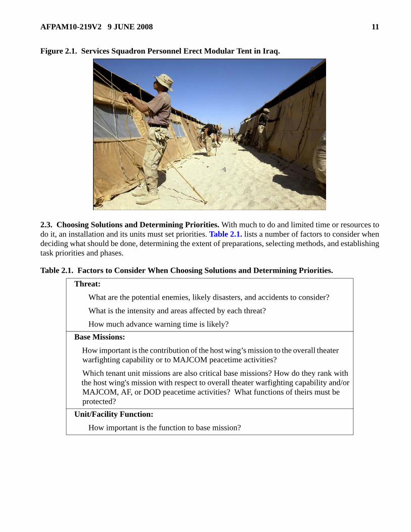
2.2.5. Every unit needs to prepare its personnel, equipment, and facilities, but not all facility prepara-tions must be done by civil engineers. With prior instruction or on-the-spot CE guidance, units can domany non-technical tasks such as sandbagging and erecting tents (Figure 2.1.). If an installation reliesentirely on its civil engineers for preparations, especially the last minute ones, the entire effort isslowed.
2.2.6. Have an occasional reality check. Make sure efforts don't conflict with those of other units.This requires more than a review of plans. It also means looking at what is being done in the field.
AFPAM10-219V2 9 JUNE 2008 11
Figure 2.1. Services Squadron Personnel Erect Modular Tent in Iraq.
2.3. Choosing Solutions and Determining Priorities. With much to do and limited time or resources todo it, an installation and its units must set priorities. Table 2.1. lists a number of factors to consider whendeciding what should be done, determining the extent of preparations, selecting methods, and establishingtask priorities and phases.
Table 2.1. Factors to Consider When Choosing Solutions and Determining Priorities.
Threat:
What are the potential enemies, likely disasters, and accidents to consider?
What is the intensity and areas affected by each threat?
How much advance warning time is likely? Base Missions:
How important is the contribution of the host wing’s mission to the overall theater warfighting capability or to MAJCOM peacetime activities?
Which tenant unit missions are also critical base missions? How do they rank with the host wing's mission with respect to overall theater warfighting capability and/or MAJCOM, AF, or DOD peacetime activities? What functions of theirs must be protected? Unit/Facility Function:
How important is the function to base mission?

12 AFPAM10-219V2 9 JUNE 2008
2.4. An Approach to Preparing Your Installation. Preparations usually focus on protecting the mostimportant base functions, protecting personnel and key assets, and getting units ready to quickly respond.Timely preparations should include a “whole base” look at the base's important functions. Integrate allhost and tenant unit functions into a prioritized list for further planning actions. One method of prioritiz-ing is to look at the function's level (national level strategic, theater level strategic, theater level tactical,or strictly tactical) when considering it's importance. An installation and its units should have game plansfor accomplishing short-notice and long-term preparations. Both are important and can be developed con-currently. Short-notice preparations focus on expedient measures and response team preparations.
2.4.1. Short-Notice Preparations. For each likely threat, decide what last-minute preparations aremost important to make when given little advance warning. Consider dividing short-notice actionsinto phases, and include the most important tasks and the long-lead-time tasks in the early phases.When logical, tie each phase to a specific threat or defense condition. Then, in theory, the tasks in aphase are started when the corresponding threat/defense condition is declared. Plans for short-noticepreparations should specify what is to be done, by whom, with what resources, and when.
2.4.1.1. First-phase efforts often involve rounding up resources (personnel, equipment, vehicles,and supplies) to be used in subsequent phases if an increase in the threat/defense condition isdeclared.
2.4.1.2. Early preparations need not provide the final solution. They can be added to or modifiedin later phases. For example, to protect an unhardened installation command and control node,civil engineers push up a 6-foot high earth berm around it in phase one. In phase two, with one CE
Vulnerability of the Function:
How vulnerable are the assets of the critical functions?
What is the location of assets for key functions versus other high-priority targets?
Are those assets concentrated or dispersed? Do they need to be located in the threat zone or likely target areas? (Because they must be close to critical activities which cannot be relocated, or the function is tied to a facility or equipment in that facility.)
Can the function be quickly and easily relocated on or off base? How long would it take to get a function partially and fully operational following relocation? Alternatives:
What options are available for protecting assets?
Are the resources available for employing those options? Effectiveness of a Preparation:
How effective is an option?
Can it be combined with one or more other options to further improve the effectiveness of the preparations? Cost:
What can the base afford?

AFPAM10-219V2 9 JUNE 2008 13
person to train them, operational support squadron personnel place sandbags on the berm andextend its height to 8 feet. This phased approach may be necessary to ensure the work which ismost important to the installation gets done first. However, phasing work can be inefficientbecause of the time required to relocate CE personnel, equipment, and materials to a previouswork site. This inefficiency is reduced when other units do some or most of their own prepara-tions.
2.4.1.3. When executing short-notice preparations, set up a work control function in the CE con-trol center (or Damage Control Center) to keep track of what CE is supposed to do and what it isactually doing. Follow the plan unless you get modifying guidance from the commander. In yourshort-notice preparation checklists, be sure to include actions targeted just for your unit as well asthose which support other installation units.
2.4.1.4. Keep short-notice preparation plans and checklists current. Add and delete actions asevents trigger the need for changes. Such events include threat changes, mission changes, and unitmoves to different or new facilities. Threats can change quickly; e.g., when a nation chooses tobecome antagonistic or an adversary chooses peace. More often threats change slowly, such aswhen a threatening nation gradually improves the number and quality of its weapons.
2.4.1.5. Keep emergency response and base recovery skills sharp. Preparations can mitigate theeffects of an enemy attack or of a natural disaster or peacetime accident, but no amount of prepa-ration can eliminate the need to respond to those crises. Preparations should enable teams torespond well and quickly. Unlike many preparations which can be done once, practicing emer-gency response and base recovery procedures must be an ongoing effort. Response teams shouldpractice often and realistically with the vehicles, equipment, tools, and materials they are expectedto use (Figure 2.2.).
Figure 2.2. Keep Response Teams’ Skills Sharp Through Realistic Practice.
2.4.1.6. Teach a core of personnel in other units how to prepare their facilities and protect theirpersonnel and key resources. Examples include laying sandbags and erecting tents. This makesthose units more self-reliant and less dependent on limited CE resources. This also makes yourpersonnel better, because they have to learn the tasks well enough to teach others. You may haveto advertise and push this service, because other units are not likely to call you. They tend to thinkmany preparations are your job. The lessons give you a chance to educate them.

14 AFPAM10-219V2 9 JUNE 2008
2.4.2. Long-Term Preparations. Make long-term preparations for each likely threat—decide whatpermanent preparations make sense. An installation needs a multi-year improvement plan for prepara-tions that are extensive, expensive, or require major construction. A plan provides focus and continu-ity since base personnel will likely change many times during the life of the plan. It should beself-explanatory, because new personnel must understand what was intended and what they must do.
2.5. Standard Preparation Actions. Table 2.2. through Table 2.7. are common disaster and attack prep-aration actions that civil engineers might make on their installation, and each will be discussed in depth insubsequent chapters. In many cases, these preparations apply to both disaster and attack activities; how-ever, some preparations may be unnecessary or impractical to do at every installation. In other cases, thepreparations may only apply to overseas installations and then only when there is a credible enemy threat.The lists are offered to stimulate ideas when developing unit plans; they are not comprehensive. Look atthe wing's Emergency Action Procedures and support plans for specific tasks. Understand that prepara-tions will never be complete. There is always something more which can be done. To keep preparations inperspective, bases and units need to have preparation plans and continue to build on those plans as cir-cumstances change.
Table 2.2. Vulnerability Reduction/Resource Protection Preparations.
FUNCTION/ ACTIVITY APPLICATION PREPARATION
Attack Disaster
Shelters
X X
Identify all facilities on the installation that could be used as shelters to protect personnel, equipment, aircraft, and armament from the effects of chemical, biological, radiological, nuclear and high-yield explosives (CBRNE) weapons, accidents involving hazardous materials, and the consequences of natural disasters where shelter in place concerns apply. (see AFI 10-2501, AFMAN 10-2602 (until rescinded), and AFMAN 10-2502 Series publications (when published).
X X Determine the capacity for each shelter and list in the CE contingency response plan and Comprehensive Emergency Management Plan 10-2.
Beddown Facilities and
Utilities X X
Identify existing facilities or potential cantonment areas, potable water sources, electricity, latrines, showers, refuse collection and disposal, and contaminated waste collection and disposal points that can be used for expedient beddown of deploying forces, federal assistance teams, pre-bundled medical supplies, and disaster victims.
Redundancy X X
Consider redundancy when designing/redesigning critical utility systems or permitting reconfiguration for continued operations, and identify facilities that can be used as substitutes if prime facilities are destroyed.

AFPAM10-219V2 9 JUNE 2008 15
Hardening
X
Consider hardening command and control nodes, access and perimeter gates, utility generating plants, and mission-essential shelters during initial construction or renovation of existing facilities. Hardening requirements for facilities located in CBRNE medium- and high-threat areas can be found in AFMAN 10-2602 until rescinded by AFMAN 10-2502 Series publications.
X
Provide design, labor, equipment, and materials to help base organizations install and repair bunkers and revetments in threat areas to protect personnel, equipment, and weapon systems from the effects of CBRNE attacks; see AFMAN 10-2602 until rescinded by AFMAN 10-2502 Series publications, and Unified Facilities Criteria (UFC) 3-340-01, Design and Analysis of Hardened Structures to Conventional Weapons Effects.
Dispersal X X
Survey and identify dispersal and evacuation sites on and off base that meet security, access, and service requirements for storing essential resources and decreasing vulnerability from a single-point attack or natural disaster. Include background data on both dispersal and evacuation sites as part of the CE contingency response plan.
Antiterrorism X
Implement actions to increase a facility’s physical and passive protection against terrorist activities; see AFI 10-245, Air Force Antiterrorism (AT) Standards, UFC 4-010-01, Design: DOD Minimum Antiterrorism Standards for Buildings, and UFC 4-021-01, Design and O&M: Mass Notification Systems. The installation Force Protection Working Group or security forces should identify the appropriate requirements.
CBRN Passive Defensive Measures
X Implement CBRN defense actions that focus on attack detection and warning, protection, and mitigation of specific threats and threat weapons.
Base Evacuation X X
Coordinate on-base evacuation plans.
Develop unit evacuation plans and procedures.
Implement base evacuation preparations according to local Comprehensive Emergency Management Plan (CEMP) 10-2 and CE Contingency Response Plan (CRP).
FUNCTION/ ACTIVITY APPLICATION PREPARATION
Attack Disaster
16 AFPAM10-219V2 9 JUNE 2008
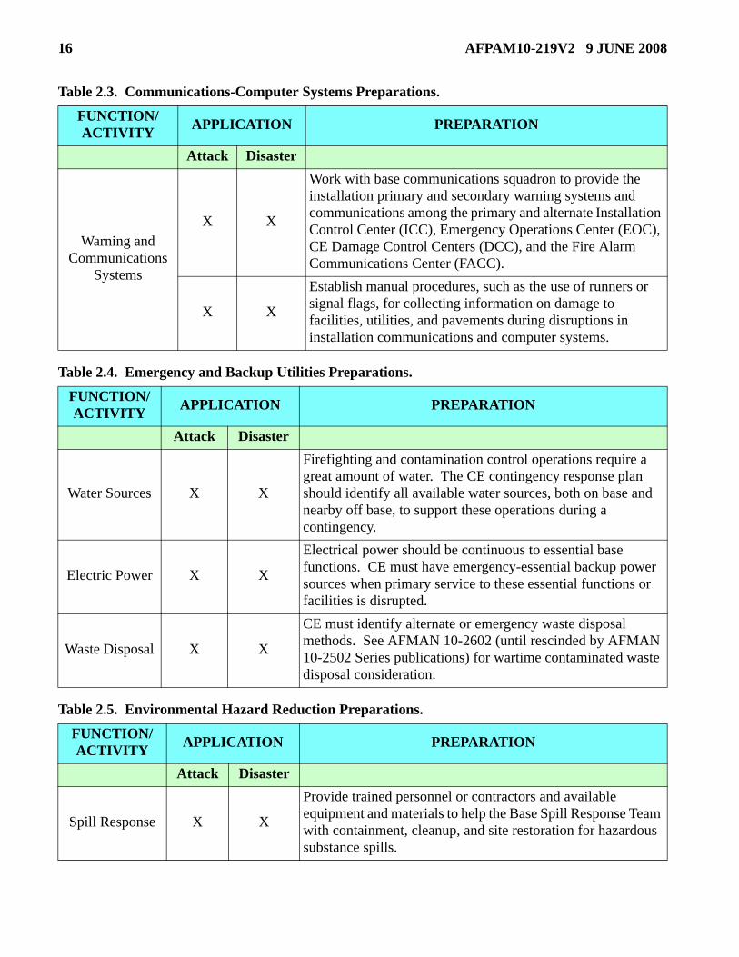
Table 2.3. Communications-Computer Systems Preparations.
Table 2.4. Emergency and Backup Utilities Preparations.
Table 2.5. Environmental Hazard Reduction Preparations.
FUNCTION/ ACTIVITY APPLICATION PREPARATION
Attack Disaster
Warning and Communications
Systems
X X
Work with base communications squadron to provide the installation primary and secondary warning systems and communications among the primary and alternate Installation Control Center (ICC), Emergency Operations Center (EOC), CE Damage Control Centers (DCC), and the Fire Alarm Communications Center (FACC).
X X
Establish manual procedures, such as the use of runners or signal flags, for collecting information on damage to facilities, utilities, and pavements during disruptions in installation communications and computer systems.
FUNCTION/ ACTIVITY APPLICATION PREPARATION
Attack Disaster
Water Sources X X
Firefighting and contamination control operations require a great amount of water. The CE contingency response plan should identify all available water sources, both on base and nearby off base, to support these operations during a contingency.
Electric Power X X
Electrical power should be continuous to essential base functions. CE must have emergency-essential backup power sources when primary service to these essential functions or facilities is disrupted.
Waste Disposal X X
CE must identify alternate or emergency waste disposal methods. See AFMAN 10-2602 (until rescinded by AFMAN 10-2502 Series publications) for wartime contaminated waste disposal consideration.
FUNCTION/ ACTIVITY APPLICATION PREPARATION
Attack Disaster
Spill Response X X
Provide trained personnel or contractors and available equipment and materials to help the Base Spill Response Team with containment, cleanup, and site restoration for hazardous substance spills.

AFPAM10-219V2 9 JUNE 2008 17
Table 2.6. Utility System Isolation Preparations.
Table 2.7. CE Support To Others.
FUNCTION/ ACTIVITY APPLICATION PREPARATION
Attack Disaster
Utility Distribution
System
X X Civil Engineer DCC and FACC maintain accurate utility distribution system drawings, showing the locations of all cutoff valves and switches.
X X Periodically, appropriate personnel should locate and operate cutoff valves and switches to ensure they are operational and control the desired systems.
X X When possible, implement GeoBase Mapping System to aid in identifying and locating critical equipment or resources.
FUNCTION/ ACTIVITY APPLICATION PREPARATION
Attack Disaster
Individual Unit Assistance X X
Provide prior instruction in shelter management, CBRN defense,contamination control, specialized teams, and other wartime andemergency management activities.
Offer units on-the-spot guidance for shelter siting and erectingtents, sandbagging, and defensive fighting positions.
Construct berms, revetments, and ditches to support unit passivedefensive measures.
Mortuary Officer X X
Provide labor and equipment to assist the mortuary officer in preparing temporary cemeteries and mass burial sites for contaminated and non-contaminated remains.
Casualty and Damage Reports
X X Assist the base in developing unit casualty and damage reporting procedures.
Maps
X X Prepare a master standard grid map or maps for installation command and control, disaster response forces, damage assessment teams, and CBRN Control Center.
X X Prepare airfield surface maps for minimum operating strip (MOS) selection teams.
X X Put copies of all maps in primary and alternate EOCs and DCCs; see AFI 10-2501, para A2.3.
Hazardous Chemicals X X Assist in the installation’s annual assessment of the hazardous
chemicals it regularly uses, stores, or ships.

18 AFPAM10-219V2 9 JUNE 2008
Table 2.8. Base Denial Preparations (Overseas Theater Task Only).
FUNCTION/ ACTIVITY APPLICATION PREPARATION
Attack Disaster
Base Denial
X CE prepares in advance a candidate list of select base systems, equipment, and supplies for potential destruction should the commander direct base evacuation and denial action.
X
Plan appropriate denial methods:
Item Evacuation.
Selective Component Removal.
Destruction.
Use of Obstacles.

AFPAM10-219V2 9 JUNE 2008 19
Chapter 3
VULNERABILITY REDUCTION AND RESOURCE PROTECTION
3.1. Introduction. Reducing the vulnerability of personnel and key resources to attacks and naturaldisasters is an important installation preparation action. Civil engineers assist in this endeavor by helpinginstallation organizations identify and program requirements to reduce the vulnerability of critical facili-ties, equipment, and personnel. Specific actions include identifying and determining the capacity of allfacilities that could be used as shelters; identifying facilities, utilities, and waste collection and disposalpoints for expedient beddown operations; identifying facilities that can be reconfigured or substituted fordestroyed facilities; considering hardening command and control facilities, access and perimeter gates,utility generating plants, and mission-essential shelters; and determining other facility hardening require-ments; surveying and identifying dispersal and evacuation sites; assisting organizations with the construc-tion and repair of bunkers and revetments; and implementing actions to increase a facility’s physical andpassive protection against terrorist activities.
3.2. Shelters. Identifying and determining the capacity of existing and potential shelters on an installa-tion can be a daunting task. It can certainly be overwhelming during the midst of a crisis. Knowing thetype and duration (long or short term) of protection needed is critical when identifying prospective shel-ters. Keep in mind that shelters used to protect personnel, equipment, aircraft, and armament from theeffects of CBRNE may vary greatly from shelters used to protect personnel from accidents involvingHAZMAT or the consequences of natural disasters. If protection against CBRNE is a primary criterion forshelter selection, review AFH 10-222 Volume 3, Guide to Civil Engineer Force Protection, and UFC3-340-01, Design and Analysis of Hardened Structures to Conventional Weapons Effects, for detailedinformation on blast effects, blast standoff distances, and other planning factors. The following para-graphs offer some factors to consider when identifying potential shelters.
3.2.1. Personnel Shelters. Depending on construction, these shelters can provide personnel protec-tion for short or long periods. Shelters intended for short-term use are generally employed for imme-diate disaster protection or to shelter personnel from the effects of weapon attacks. Short-term sheltersgenerally offer expedient protection and are normally occupied just before and during a disaster orattack and may not provide protection and utilities for extended living. In contrast, long-term shelters(often used for disaster relief and incoming personnel) may be occupied for extended periods, offerprotection from the elements, and when appropriately hardened, may provide limited protection fromsmall arms weapons fire, shell fragments, and the effects of chemical, biological, radiological, andnuclear (CBRN) weapons.
3.2.1.1. Short-Term Shelters. Such shelters may be existing permanent facilities (Shelter inPlace) or temporary structures constructed from locally available materials. They may also be con-structed using prefabricated concrete modular forms, commercial off-the-shelf (COTS) items, orbuilt by local contractors. These shelters may be the only alternative when there are not enoughpermanently hardened facilities in the right locations. This is especially true in bare base or dis-persed operations. The best short-term shelter is usually one that provides the most protection butrequires the least amount of effort to construct. Shelters should have as much overhead cover aspossible. They should be limited to about 25 personnel and dispersed. When possible, sheltersshould be hidden next to buildings, on the back sides of hills, in woods, or in natural depressionsin the terrain; but out of drainage paths. Below-ground shelters require the most construction

20 AFPAM10-219V2 9 JUNE 2008
effort but generally provide the highest level of protection from conventional and chemical weap-ons. Aboveground shelters provide the best observation and are easier to enter and exit thanbelow-ground shelters. They provide the least amount of protection from conventional weapons;however, they do provide protection against liquid droplets of chemical agents. Abovegroundshelters are used when water levels are close to the ground surface or when the ground is so hardthat digging a below-ground shelter is impractical. Defensive bunkers and fighting positions forbase defense and antiterrorism measures are also short-term shelters and are addressed in AFH10-222, Volume 14, Guide to Fighting Positions, Obstacles, and Revetments.
3.2.1.2. Long-Term Shelters. Air bases often identify and use existing permanent facilities forshelters that will be occupied for periods longer than a few hours. However, temporary shelters(Figure 3.1.) such as TEMPER tents, Alaska Small Shelter Systems, COTS products, and othersmay be used when permanent facilities are not available. In some cases, temporary facilities aremodified to support extended living and may even be hardened to protect against attack. Specificfactors to consider for extended shelter occupation include space, structure, ventilation, water sup-ply, health and sanitation, electrical power, and food. Each factor is discussed below. These factorsare also vital to long-term shelters and facilities used during expedient beddown operationsaddressed in Chapter 6.
Figure 3.1. Temporary Shelters May Be Used for Extended Periods When Necessary.
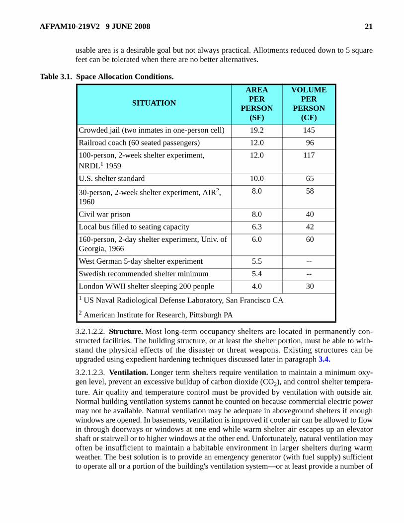
3.2.1.2.1. Space. Physical space for human occupancy is the first shelter requirement. Theapproximate volume required for an adult is 2.3 cubic feet. While history has recorded cases ofcrowding for extended periods to this level, personnel will not voluntarily stay in these condi-tions. Many studies have been conducted to determine the minimum shelter space allocationstandard. The US uses an area of 10 square feet (about the space an adult occupies when lyingdown) and 65 cubic feet of volume per person. Table 3.1. shows how this standard relates toother situations where personnel are or were confined. The US standard is spacious comparedto other experiences; particularly wartime. Some experienced European nations recommendone-half meter (about 5.4 square feet) as a minimum. The recommended 10 square feet of
AFPAM10-219V2 9 JUNE 2008 21
usable area is a desirable goal but not always practical. Allotments reduced down to 5 squarefeet can be tolerated when there are no better alternatives.
Table 3.1. Space Allocation Conditions.
3.2.1.2.2. Structure. Most long-term occupancy shelters are located in permanently con-structed facilities. The building structure, or at least the shelter portion, must be able to with-stand the physical effects of the disaster or threat weapons. Existing structures can beupgraded using expedient hardening techniques discussed later in paragraph 3.4.
3.2.1.2.3. Ventilation. Longer term shelters require ventilation to maintain a minimum oxy-gen level, prevent an excessive buildup of carbon dioxide (CO2), and control shelter tempera-ture. Air quality and temperature control must be provided by ventilation with outside air.Normal building ventilation systems cannot be counted on because commercial electric powermay not be available. Natural ventilation may be adequate in aboveground shelters if enoughwindows are opened. In basements, ventilation is improved if cooler air can be allowed to flowin through doorways or windows at one end while warm shelter air escapes up an elevatorshaft or stairwell or to higher windows at the other end. Unfortunately, natural ventilation mayoften be insufficient to maintain a habitable environment in larger shelters during warmweather. The best solution is to provide an emergency generator (with fuel supply) sufficientto operate all or a portion of the building's ventilation system—or at least provide a number of
SITUATION
AREA PER
PERSON (SF)
VOLUME PER
PERSON (CF)
Crowded jail (two inmates in one-person cell) 19.2 145 Railroad coach (60 seated passengers) 12.0 96 100-person, 2-week shelter experiment, NRDL1 1959
12.0 117
U.S. shelter standard 10.0 65
30-person, 2-week shelter experiment, AIR2, 1960
8.0 58
Civil war prison 8.0 40 Local bus filled to seating capacity 6.3 42 160-person, 2-day shelter experiment, Univ. of Georgia, 1966
6.0 60
West German 5-day shelter experiment 5.5 -- Swedish recommended shelter minimum 5.4 -- London WWII shelter sleeping 200 people 4.0 30 1 US Naval Radiological Defense Laboratory, San Francisco CA 2 American Institute for Research, Pittsburgh PA

22 AFPAM10-219V2 9 JUNE 2008
pedestal fans for this purpose. Other options include using aerospace ground equipment(AGE) ground air conditioning units from the flightline or spare environmental control units(ECU). Both types of units can be ducted directly into the shelter or tied into the shelter's airdistribution ducts. If entry of CBRN contamination is an issue, CBRN filters must be installedin the ventilation system.
3.2.1.2.3.1. Fresh air contains about 21 percent oxygen; when the oxygen content dropsbetween 19.5 and 17.5 percent, the Occupational Safety and Health Administration(OSHA) considers a confined space to be oxygen depleted. Below 17.5 percent, workersare required to be on supplied air. Studies have shown that healthy young adults can sur-vive without long-term effects at an oxygen level as low as 14 percent, but they cannot per-form sustained vigorous activities. Fortunately, it takes only 0.4 cubic feet of fresh air perminute per person to maintain the oxygen level at 17.5 percent.
3.2.1.2.3.2. CO2 concentration is a bigger problem. The results of prolonged exposure tohigher levels of CO2 have shown the desirability of keeping the level below 1 percent. TheFederal Emergency Management Agency (FEMA) has established a goal of not more than0.5 percent. This limit requires 3 cubic feet of fresh air per minute per person, which morethan satisfies the oxygen requirement as well.
3.2.1.2.3.3. In addition to consuming oxygen and generating CO2, shelter occupants pro-duce an average of 500 British Thermal Units (BTU) per hour. Part of that heat is given offas “sensible” heat that can be measured by a thermometer. The other part is given off inwater vapor as “latent” heat. During winter months, this may be very welcome heat. How-ever, during summertime, proper ventilation is needed to rid a shelter of excess heat andmoisture to prevent body temperatures from rising to dangerous levels. As long as the airtemperature is well below skin temperature, the body can radiate heat to maintain normaltemperature. At higher temperatures, the body must rely on evaporative cooling by perspi-ration. If the air is humid and air movement low, evaporative cooling loses its effective-ness, and body temperature will rise.
3.2.1.2.3.4. The most widely used measure of heat and moisture effects on the humanbody is “effective temperature” (ET). It combines the effects of air temperature, air mois-ture, and air movement to yield equal sensations of warmth or cold and approximatelyequal amounts of heat strain. The numerical value of ET is the reading on an ordinary ther-mometer when the air is completely saturated (100 percent relative humidity). At less than100 percent, the thermometer reading would be higher than the equivalent effective tem-perature. For a relative humidity of more than 50 percent, a common summertime level, aneffective temperature of 82 degrees would correspond to air temperatures in the mid-90s.
3.2.1.2.3.5. Using 82 degrees as the minimum effective temperature, the map in Figure3.2. defines the required ventilation (in cubic feet per minute per person) in the differentzones in the US. The ventilation provides 90 percent reliability of maintaining the effectivetemperature in the shelter at 82 degrees or less. As you can see, the required ventilationrates are all greater than the 3 cubic feet per minute per person needed to control the CO2buildup. Therefore, adequate ventilation to maintain effective temperature also providessufficient oxygen and control of CO2 buildup.

AFPAM10-219V2 9 JUNE 2008 23
Figure 3.2. Required Ventilation to Control Temperature (Cubic Ft. Per Min. Per Person).
3.2.1.2.4. Water Supply. An assured water supply is important if the shelter is to be occupiedfor an extended period. During wintertime, or in an uncrowded shelter, 3.5 gallons per personwill last for approximately 2 weeks; this may last only 3 days in hot weather. Figure 3.3. illus-trates the relationship of required water versus shelter air temperature. Given an abundance ofwater, people can drink extra water to help compensate for deficiencies in temperature control,but do not count on normal water sources. Having sufficient quantities of water often creates astorage problem (as does disposal of liquid wastes). Plastic and metal trash cans, with plasticbags as liners, are suitable and readily available as are 1-gallon plastic jugs and 5-gallon plas-tic cans.
Figure 3.3. Minimum Water Required.

24 AFPAM10-219V2 9 JUNE 2008
3.2.1.2.4.1. When water intake is restricted or negligible, the bodies of healthy peoplecompensate by reducing the amount of urine excretion by about half, from about 3 pounds(pints) in adults to about 1-1/2 pounds. Unless people are required to perspire to lose bodyheat, about 1 quart of water suffices to maintain the water balance. If the shelter tempera-ture is warm, however, the amount of water needed to avoid dehydration increases rapidly.This is another reason to be concerned about temperature control in shelters.
3.2.1.2.4.2. The consequences of dehydration vary widely among individuals, with thevery young, very old, and ill being especially vulnerable. Pregnant women require morewater than usual and must avoid dehydration to prevent injury to the unborn child. Gener-ally there is nothing to be gained by stretching out inadequate water supplies to cover apresumed shelter stay. Health is best maintained by delaying any dehydration as long aspossible. Water management should be aimed at ensuring adequate intake and preventingwaste rather than at rationing the available supply, particularly since there is no way todetermine a “fair share” for each person except by satisfying thirst.
3.2.1.2.4.3. Water for washing is an amenity and not a necessity for an extended shelterstay.
3.2.1.2.5. Health and Sanitation. Minimizing the spread of disease or infection requires con-stant attention to sanitation measures, cleanliness of toilet areas, careful handling of water andfood, and establishment of an isolation area for personnel who are ill. The disposal of humanwaste is the highest priority sanitation need. The emergency standard is one commode per 50people. Shelter areas will have few conventional commodes, if any, and flushing water mustbe limited. Toilet facilities can still be used, however. The contents of chemical toilets can bedisposed of by dumping into the conventional toilets. If water is available, those toilets can beflushed occasionally. Otherwise, emptied water containers, plastic bags, or other containersmust be used to store wastes. As a rough rule of thumb, waste storage capacity must be able tohandle about 1/2 gallon of sewage per person per day.
3.2.1.2.5.1. Portable chemical toilets are the best substitute for the lack of conventionaltoilets. Makeshift commodes can be made by lining large cans with heavy-duty plasticbags and improvising a seat with a pair of boards or cutting a hole in plywood. Disinfectant(chlorine, bleach, etc.) should be poured in periodically to fight germs and odors. If humanwaste must be stored, plastic bags from chemical commodes can be tied off when nearlyfull and placed in large covered garbage cans. Double bag the waste to prevent spills if abag tears.
3.2.1.2.5.2. Keeping toilet areas and toilets clean is a big part of preventive medicine.Unless the shelter space is part of a facility occupied in peacetime, janitorial and cleaningsupplies, such as trash cans, brooms, and mops, are not usually available. Additional sup-plies of heavy-duty plastic bags are invaluable.
3.2.1.2.5.3. Bathing is not a necessity, but some water is needed to allow food handlers towash their hands; this reduces the transmission of disease.
3.2.1.2.5.4. Perform good housekeeping practices as much as possible. Substantialamounts of litter and trash accumulate in a crowded shelter. This ranks high on a shelter“discomfort index.”
AFPAM10-219V2 9 JUNE 2008 25
3.2.1.2.6. Electrical Power. As eluded to earlier, emergency power is important for ventila-tion, but it is also needed to provide limited lighting in the shelter. Lighting levels need only besufficient for personnel to navigate within the shelter and find exits, although sufficient light-ing for reading helps morale. Excess lighting adds to the heat load, which is unwelcome in hotconditions.
3.2.1.2.7. Food. Providing food is not a CE responsibility, but the packaging and types offood consumed can affect water consumption, shelter heat load, and waste generation. CEplanners should coordinate with shelter planners to address requirements affected by shelterfood stocks. Food is near the end of the list of essential shelter needs. Healthy adults can sur-vive without food for several weeks given adequate water and temperature conditions. Thisdoes not consider the emotional impact. People consider food a basic and will likely leave theshelter if it is not available. If shelter occupants are expected to participate in base recoveryoperations, they must eat. Foods high in protein or fat greatly increase the amount of drinkingwater required to eliminate wastes. A diet composed entirely of carbohydrates is also undesir-able. Heating or cooking foods adversely affects temperature control, requires an assured heatsource, and can constitute a hazard in a crowded shelter. Foods that require cooking or eatingutensils or that produce garbage or trash offer sanitation problems. Perishable foods are notrecommended and, if brought in, should be consumed first. The “best” foods are crackers andcanned goods which are easy to transport, store, and prepare, as are whole-grain cereal prod-ucts and dried fruits. Augmentation with food products that are mostly liquid is desirable.Glass containers present a problem and should be handled with care if they cannot be avoided.Shelter occupants should bring ready-to-eat food to supplement any shelter stocks.
3.2.1.3. Collective Protection. Collective protection is an important factor when determiningpersonnel shelter requirements. Ideally, it provides a temperature-controlled, contamination-freeenvironment to allow personnel relief from continuous wear of individual protective equipment(IPE). The basic concept for most facility collective protection solutions is to provide overpres-sure, filtration, and controlled entry and exit. Maintaining a higher internal air pressure than exter-nal pressure and filtering incoming air prevent contaminated external air from infiltrating theshelter. Other types of collective protection rely on the facility structure to provide short-term pro-tection. They are not equipped with positive pressure air filtration systems or airlocks and useshelter-in-place techniques to limit or delay the entry of contamination. Collective protection sup-ports two mission sustainment areas that quickly erode in a CBRN environment: personnel restand relief (breaks and sleeping) and work relief (command and control, medical treatment, mis-sion-oriented protective posture (MOPP) recovery time after maximum work effort). Each instal-lation must assess collective protection requirements based upon the likely threats and missionrequirements. Specific collective protection solutions may include a mixture of permanent, mobileor transportable, or expedient or temporary collective protection systems. Refer to AFMAN10-2602 (until rescinded by AFMAN 10-2502, Series publication) for more detailed informationon shelters with collective protection systems.
3.2.1.4. Nuclear Protection. The design and construction of shelters to resist the direct effects(versus a direct hit) of nuclear weapons are complex, costly, and beyond the scope of this publica-tion. Considerable information is available on the construction, preparation, and operation of shel-ters to protect personnel from the direct effects of a nuclear blast and from radioactive fallout.Refer to AFMAN 10-2602 (until rescinded by AFMAN 10-2502 Series publications), AFTTP (I)
26 AFPAM10-219V2 9 JUNE 2008
3-2.46, Multiservice Tactics, Techniques, and Procedures for Nuclear, Biological, and Chemical(NBC) Protection, and UFC 3-340 series publications.
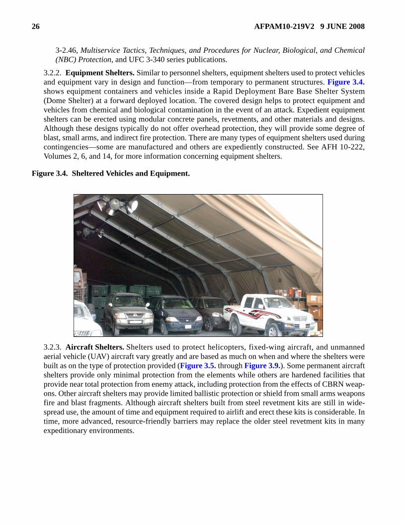
3.2.2. Equipment Shelters. Similar to personnel shelters, equipment shelters used to protect vehiclesand equipment vary in design and function—from temporary to permanent structures. Figure 3.4.shows equipment containers and vehicles inside a Rapid Deployment Bare Base Shelter System(Dome Shelter) at a forward deployed location. The covered design helps to protect equipment andvehicles from chemical and biological contamination in the event of an attack. Expedient equipmentshelters can be erected using modular concrete panels, revetments, and other materials and designs.Although these designs typically do not offer overhead protection, they will provide some degree ofblast, small arms, and indirect fire protection. There are many types of equipment shelters used duringcontingencies—some are manufactured and others are expediently constructed. See AFH 10-222,Volumes 2, 6, and 14, for more information concerning equipment shelters.
Figure 3.4. Sheltered Vehicles and Equipment.
3.2.3. Aircraft Shelters. Shelters used to protect helicopters, fixed-wing aircraft, and unmannedaerial vehicle (UAV) aircraft vary greatly and are based as much on when and where the shelters werebuilt as on the type of protection provided (Figure 3.5. through Figure 3.9.). Some permanent aircraftshelters provide only minimal protection from the elements while others are hardened facilities thatprovide near total protection from enemy attack, including protection from the effects of CBRN weap-ons. Other aircraft shelters may provide limited ballistic protection or shield from small arms weaponsfire and blast fragments. Although aircraft shelters built from steel revetment kits are still in wide-spread use, the amount of time and equipment required to airlift and erect these kits is considerable. Intime, more advanced, resource-friendly barriers may replace the older steel revetment kits in manyexpeditionary environments.

AFPAM10-219V2 9 JUNE 2008 27
Figure 3.5. Engineers Build Aircraft Shelters from B-1 Steel Revetment Kits.
Figure 3.6. HESCO Barriers Provide Limited Shelter for Aircraft.
Figure 3.7. Airmen Push Aircraft Into Hardened Aircraft Shelter.
28 AFPAM10-219V2 9 JUNE 2008
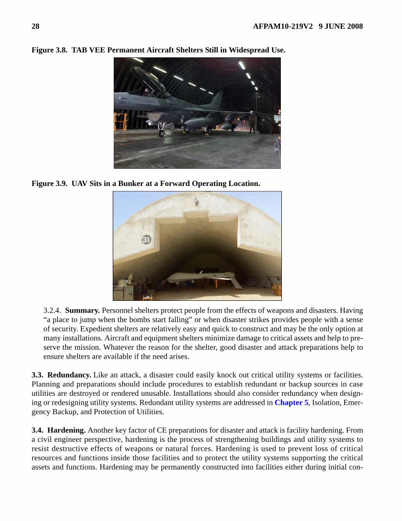
Figure 3.8. TAB VEE Permanent Aircraft Shelters Still in Widespread Use.
Figure 3.9. UAV Sits in a Bunker at a Forward Operating Location.
3.2.4. Summary. Personnel shelters protect people from the effects of weapons and disasters. Having“a place to jump when the bombs start falling” or when disaster strikes provides people with a senseof security. Expedient shelters are relatively easy and quick to construct and may be the only option atmany installations. Aircraft and equipment shelters minimize damage to critical assets and help to pre-serve the mission. Whatever the reason for the shelter, good disaster and attack preparations help toensure shelters are available if the need arises.
3.3. Redundancy. Like an attack, a disaster could easily knock out critical utility systems or facilities.Planning and preparations should include procedures to establish redundant or backup sources in caseutilities are destroyed or rendered unusable. Installations should also consider redundancy when design-ing or redesigning utility systems. Redundant utility systems are addressed in Chapter 5, Isolation, Emer-gency Backup, and Protection of Utilities.
3.4. Hardening. Another key factor of CE preparations for disaster and attack is facility hardening. Froma civil engineer perspective, hardening is the process of strengthening buildings and utility systems toresist destructive effects of weapons or natural forces. Hardening is used to prevent loss of criticalresources and functions inside those facilities and to protect the utility systems supporting the criticalassets and functions. Hardening may be permanently constructed into facilities either during initial con-

AFPAM10-219V2 9 JUNE 2008 29
struction or added later as supplemental hardening. Permanent hardening is accomplished during peace-time, because there is not enough time for detailed engineering designs or elaborate construction when anenemy or disaster threatens. More often, engineers are called on in an expeditionary environment to pro-vide expedient hardening, such as rapidly erecting a sandbag wall or building protective barriers and soilberms. Preparations for hardening are addressed in the following paragraphs.
3.4.1. Selection of Candidates for Hardening. The responsibility for the selection of facilities andequipment that must be protected by hardening does not rest with the base civil engineer (BCE). TheBCE is, however, responsible for ensuring that the hardening process is accomplished. Normally,items which are most essential to continuing the base mission receive priority for protection. Aircraft,command and control centers, personnel shelters, and communications centers are typical high-prior-ity facilities that are good candidates for hardening.
3.4.2. Hardening Design. For permanent hardening, an engineer must perform a structural analysisto determine the hardening method. To perform this analysis, the threat, in terms of type of weapon(munitions), fuzing, size, angle of impact, etc., must be known. The engineer must also understand thefunction of the facility. For supplemental hardening or facility retrofits, this involves evaluating eachstructural component versus the expected weapon type and size. Because this analysis is very detailed,it is only conducted for permanent construction or peacetime retrofit of existing structures.
3.4.3. Expedient Hardening Considerations and Factors. There are many ways to upgrade thehardness of existing non-hardened facilities and to protect critical resources from the effects of con-ventional weapons. This section outlines basic factors to consider and techniques for expedient hard-ening of facilities (see Table 3.2.).
Table 3.2. Factors to Consider for Expedient Hardening.
3.4.3.1. Threat. Understanding threat weapons and their effects on facilities is the first step inselecting and designing hardening measures. The variety of weapons available for attacking Air
Expedient Hardening Considerations Threat (in terms of weapon effects). Number of resources and facilities to be protected and the characteristics of each. Type and dimensions of aircraft to be protected. Layout of aircraft parking areas. Time available for design and construction. Materials available. Expected duration of use. Equipment and labor needed for construction. Soil conditions (type, moisture, pH, etc). Drainage (both surface and off roofs). Terrain. Weather.

30 AFPAM10-219V2 9 JUNE 2008
Force facilities is almost unlimited, ranging from small arms to heavy weapons delivered aerially.Weapon effects often occur in combination for greater lethality. The detonation of a general- pur-pose bomb is a good example of a one-two punch. The impact of high velocity fragments from thebomb casing can weaken a structure, making the blast wave immediately following detonationmore effective in destroying the structure. Fragment and projectile penetration typically controlsthe design of the hardening method used. Additional information on weapons and their effects canbe found in AFMAN 10-2602 (until rescinded by AFMAN 10-2502 Series publications), and UFC3-340-01.
3.4.3.2. Resources and Facilities to Be Protected. Civil engineers should prepare a hardeninganalysis for each resource and facility to be upgraded. Each structural component should be eval-uated against the effects of the probable threat weapons and the expected duration of use to deter-mine design features. If aircraft are to be protected, consider the length, wingspan, and height ofthe aircraft. Also consider the layout of aircraft parking areas. If conducted in peacetime, thesehardening analyses provide the basis for the installation's permanent and expedient hardeningplans. Exhaustive field investigations and elaborate plans are not necessary, but adequate siteinvestigations are important and help reduce the number of problems caused by immediate deci-sions based on a sense of urgency.
3.4.3.3. Time. Normally, the nearer an air base is to the potential battle area, the more vital thetime element becomes. Time is saved by efficient use of manpower, heavy equipment, hand tools,materials, and other facilities available. Good planning, scheduling, and supervision are neededduring construction. Develop task priorities and assign crews and equipment to specific workareas to minimize travel. Sequence operations so all equipment is kept busy.
3.4.3.4. Materials. Hardening materials act as either shielding (for protecting personnel or criti-cal resources), serve as structural components (to hold the shielding in place), or perform bothfunctions at the same time. Shielding provides protection against penetration of projectiles andfragments, nuclear and thermal radiation, and the effects of fire and chemical agents. When time islimited, materials must be conserved, particularly those shipped from the continental UnitedStates (CONUS). Local materials should be used whenever practicable. Some possible hardeningmaterials are discussed in the following paragraphs.
3.4.3.4.1. Soil. Soil is generally the primary fill material for revetments and soil berms. Pro-jectile and fragment penetration in soil is based on three considerations: for materials of thesame density, the finer the grain the greater the penetration; penetration decreases withincrease in density; and penetration increases with greater water content.
3.4.3.4.2. Soil Cement. Soil cement is used mostly for revetments which use sandbags intheir construction. Soil cement can also be used in the construction of caps for earth revet-ments and to stabilize soil foundations under revetments. The standard ratios are one partcement to ten parts soil by weight or one part cement to six parts sand or gravel.
3.4.3.4.3. Steel. Many expedient types of steel may be available for shielding. Sheet piling,steel landing mats, and culvert sections can be used in a protective structure as one of severalcomposite materials. The thickness of these materials is a key factor in determining the overallpenetration resistance of the revetment. Steel plate, only 1/6 the thickness of concrete, affordsequal protection against small and intermediate caliber projectiles. Steel is also more likely todeform a projectile as it penetrates and is much less likely to spall than concrete. Steel sheets

AFPAM10-219V2 9 JUNE 2008 31
can be used to confine soil in a soil revetment. However, material with perforations larger than1/2 inch do not properly confine the soil material.
3.4.3.4.4. Concrete. Concrete provides a very permanent revetment medium. If used withreinforcing bars or mesh, concrete is quite resistant to fragmentation shells. Reinforcing helpsthe concrete stay intact even after excessive cracking caused by penetration. When a shell orbomb explodes, its fragments travel faster than the blast wave. If these fragments strike theexposed concrete surfaces of a protective position, they can weaken the concrete to such anextent that the blast wave destroys it. Fragment strikes on exposed concrete surfaces may alsocause spalls or pop-offs, on the inside surface of the concrete wall. Traveling at high speeds,the pop-offs create a hazard to personnel and materials on the inside. When possible, at leastone layer of sandbags, placed on their short ends, or 15 inches of soil should cover all exposedconcrete surfaces. Concrete construction requires skilled personnel and specialized equipment.Unfortunately, Portland cement may not be readily available after a conflict begins.
3.4.3.4.5. Rock. In areas where rock is readily available, it can be an excellent hardeningmaterial. Fragment penetration into rock depends on the rock's physical properties and thenumber of joints, fractures, and other irregularities contained in the rock. Several layers ofirregularly-shaped rock can change the angle of penetration. Hard rock can cause a projectileor fragment to flatten out or break up and stop penetration. Brick and masonry have the sameprotection characteristics and limitations as rock. Large rock is often used as a burster layer.
3.4.3.4.6. Snow and Ice. Although snow and ice have only limited applications, they mayoccasionally be the only readily available materials in some areas. They should be used forshielding only. Weather changes can cause protective structures made of snow and ice to wearaway or even collapse.
3.4.3.4.7. Dimensioned Wood Timbers. Because of its low density and relatively low com-pressive strength, wood should generally be used only as structural support for survivabilitypositions. Much greater thicknesses of wood than of soil are needed for protection from pene-tration. Timber is better used to construct retaining walls for earth or sandbag revetments orused to construct stand-offs. The timber may be hard or soft wood but should be free of knotsor other imperfections that would affect its strength and resistance to penetration. Timberwhich is used against earth should be treated with tar or creosote to prevent decay.
3.4.3.4.8. Plywood. Multiple layers of plywood can be used as a very effective field expedi-ent protective wall. The wall must be designed and constructed with sufficient braces andanchors to provide stability against blast. Most often plywood is used as a barrier to containsoil in a retaining wall or revetment.
3.4.3.4.9. Logs. In heavily forested areas, timbers may be cut from existing woodlands andused to make log revetments. Logs can be better used as the walls in a soil bin revetment.
3.4.3.4.10. Corrugated Metal. This material can be used to assemble revetment retainingwalls and bulkheads. Since corrugated metal is not as rigid as landing mat and other steelmaterial, it requires additional vertical and horizontal support to withstand the pressure of theearth fill.
3.4.3.4.11. Boxes. Many types of boxes available on a typical installation can be filled withearth and used to construct a revetment. Ammunition boxes filled with earth provide someprotection as retaining walls and bulkheads if they are adequately reinforced with vertical sup-

32 AFPAM10-219V2 9 JUNE 2008
ports. CONEX or similar type containers filled with dry earth make formidable protectivewalls.
3.4.3.4.12. Combined Materials. In most contingency situations, the availability of con-struction materials and skilled workers will likely be limited and will vary by installation. Thismight require a combination of expedient methods to insure that effective protection is sup-plied. In fact, if the materials are available, the combined use of materials normally results in amore effective revetment.
3.4.3.5. Equipment and Labor. Selection of the hardening method should be based on resourcesrequired, resources available, and other subjective factors. As in any design situation, more thanone solution may be possible or close to optimal. Adequate protection may also require the use ofmore than one method. For example, bin revetments may be selected to protect the structure wallswhile sandbags and loose soil are used to cover the roof. A number of innovative concepts are pos-sible for expedient hardening. Table 3.3. shows the equipment, labor, materials, and spacerequired for the various methods. A quick screening of each of the methods can be performedusing this table. For example, if space is very limited, soil berms are not usually an option. Alsosome methods such as sand grid forms require special materials.
Table 3.3. Design, Construction, and Special Considerations Matrix.
METHOD EQUIPMENT LABOR MATERIALS SPACE (TYPICAL)
Soil Berm Backhoe/Loader Hand Shovel1
Truck/Trailer5 Unskilled2,3 Soil4 >6 ft
Sandbags Hand Shovel Truck/Trailer5 Unskilled3
Soil/Gravel Bags or other expedient container6
1-4 ft
Sand Grids Backhoe/Loader Hand/Shovel1
Truck/Trailer5 Unskilled2,3 Soil/Gravel Grid Forms ~3 ft
Modular Concrete
Revetments Crane/Forklift Unskilled Skilled2
Precast Modular Units Straps and bolts for connections Sandbags7
4-8 ft
Bin Revetments
Backhoe/Loader Hand Shovel1
Crane/Forklift Truck/Trailer5
Unskilled Skilled2
Soil/Gravel/Rock Rubble Container Straps & bolts for connections Sandbags7
2-10 ft

AFPAM10-219V2 9 JUNE 2008 33
3.4.3.6. Topography. The topography of the area near the deployment site should be consideredwhen determining the protective requirements for parked aircraft, other vital assets, and key facil-ities. High ground within a range of 3,500 meters (11,483 feet) that offers good observation foreffective mortar or direct fire may destroy the effectiveness of revetments unless the air basedefense force plans for effective counter-fire. Similarly, wooded areas, villages, or other sites per-mitting concealment close to parked aircraft give opportunities for guerrillas and terrorists toassemble. These factors indicate a need for active defense measures in addition to passive fortifi-cation.
3.4.3.7. Terrain. Slopes, drainage, vegetation, character of soil, likelihood of floods, and otherconditions that may affect construction and layout should be studied.
3.4.3.8. Effects of Soil Moisture. Wet soil may be used for revetments if dry material cannot beobtained, but it is uneconomical since larger quantities are required to resist penetration. Wet soilmust be approximately one-half again as thick as dry soil to resist penetration by a given type ofammunition. Thus, selecting dry soil for earth revetments and providing a waterproof cover forthem conserves manpower and materials. Of the various soils, wet clay can be penetrated mosteasily and is the least effective revetment material. Dry sand has the most resistance to penetrationand therefore is the most desirable soil for revetment purposes. Soils with high moisture content,if not well protected from the elements, give way to erosion in a relatively short period.
3.4.3.9. Impact of Weather. The local weather is an important factor in the development of hard-ened structures. Areas with high amounts of rainfall cause earth-filled revetments and sandbagstructures to lose some of their effectiveness. Dampness also has an adverse effect on the durabil-
Sacrificial Panels Crane/Forklift
Unskilled Skilled2
Engineering8
Varies9
Hardware for connections <1 ft
1 Hand construction/shovel filling possible if heavy equipment unavailable. 2 Skilled labor required for operation of heavy equipment. 3 Engineering required for determination of allowable loads when placed overhead or against nonhardened walls (berms only). 4 Requires facing to control erosion and blowing dust problems. 5 For transport of fill material if not available at site. 6 Acrylic fabric bags recommended for durability. 7 Sandbags should be used to protect corners of revetment array. 8 Engineering design required for thickness of panel, sizing of air space, and design of structural attachment. 9 A variety of materials may be used, from plywood to asphalt to concrete to modern composites.
METHOD EQUIPMENT LABOR MATERIALS SPACE (TYPICAL)
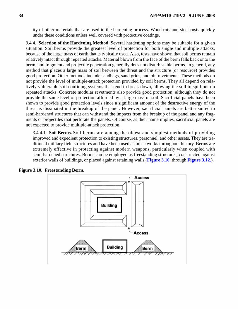
34 AFPAM10-219V2 9 JUNE 2008
ity of other materials that are used in the hardening process. Wood rots and steel rusts quicklyunder these conditions unless well covered with protective coatings.
3.4.4. Selection of the Hardening Method. Several hardening options may be suitable for a givensituation. Soil berms provide the greatest level of protection for both single and multiple attacks,because of the large mass of earth that is typically used. Also, tests have shown that soil berms remainrelatively intact through repeated attacks. Material blown from the face of the berm falls back onto theberm, and fragment and projectile penetration generally does not disturb stable berms. In general, anymethod that places a large mass of soil between the threat and the structure (or resource) providesgood protection. Other methods include sandbags, sand grids, and bin revetments. These methods donot provide the level of multiple-attack protection provided by soil berms. They all depend on rela-tively vulnerable soil confining systems that tend to break down, allowing the soil to spill out onrepeated attacks. Concrete modular revetments also provide good protection, although they do notprovide the same level of protection afforded by a large mass of soil. Sacrificial panels have beenshown to provide good protection levels since a significant amount of the destructive energy of thethreat is dissipated in the breakup of the panel. However, sacrificial panels are better suited tosemi-hardened structures that can withstand the impacts from the breakup of the panel and any frag-ments or projectiles that perforate the panels. Of course, as their name implies, sacrificial panels arenot expected to provide multiple-attack protection.
3.4.4.1. Soil Berms. Soil berms are among the oldest and simplest methods of providingimproved and expedient protection to existing structures, personnel, and other assets. They are tra-ditional military field structures and have been used as breastworks throughout history. Berms areextremely effective in protecting against modern weapons, particularly when coupled withsemi-hardened structures. Berms can be employed as freestanding structures, constructed againstexterior walls of buildings, or placed against retaining walls (Figure 3.10. through Figure 3.12.).
Figure 3.10. Freestanding Berm.
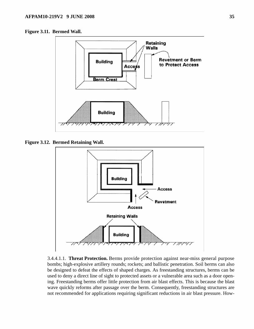
AFPAM10-219V2 9 JUNE 2008 35
Figure 3.11. Bermed Wall.
Figure 3.12. Bermed Retaining Wall.
3.4.4.1.1. Threat Protection. Berms provide protection against near-miss general purposebombs; high-explosive artillery rounds; rockets; and ballistic penetration. Soil berms can alsobe designed to defeat the effects of shaped charges. As freestanding structures, berms can beused to deny a direct line of sight to protected assets or a vulnerable area such as a door open-ing. Freestanding berms offer little protection from air blast effects. This is because the blastwave quickly reforms after passage over the berm. Consequently, freestanding structures arenot recommended for applications requiring significant reductions in air blast pressure. How-
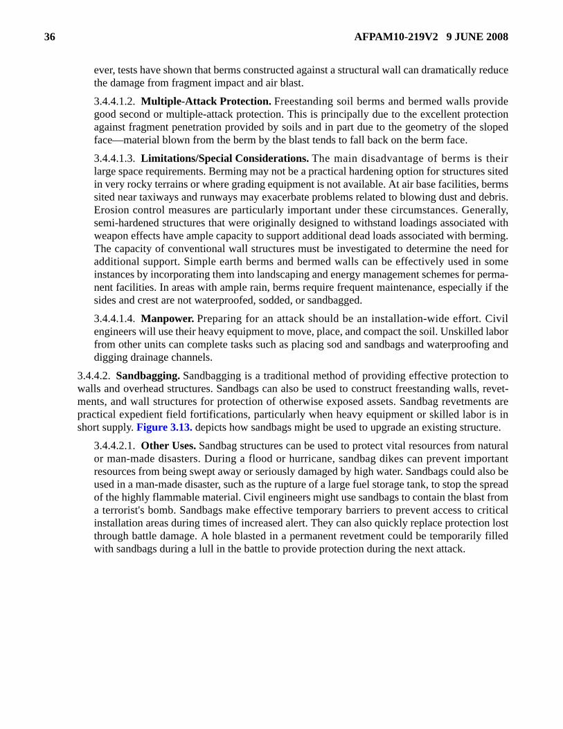
36 AFPAM10-219V2 9 JUNE 2008
ever, tests have shown that berms constructed against a structural wall can dramatically reducethe damage from fragment impact and air blast.
3.4.4.1.2. Multiple-Attack Protection. Freestanding soil berms and bermed walls providegood second or multiple-attack protection. This is principally due to the excellent protectionagainst fragment penetration provided by soils and in part due to the geometry of the slopedface—material blown from the berm by the blast tends to fall back on the berm face.
3.4.4.1.3. Limitations/Special Considerations. The main disadvantage of berms is theirlarge space requirements. Berming may not be a practical hardening option for structures sitedin very rocky terrains or where grading equipment is not available. At air base facilities, bermssited near taxiways and runways may exacerbate problems related to blowing dust and debris.Erosion control measures are particularly important under these circumstances. Generally,semi-hardened structures that were originally designed to withstand loadings associated withweapon effects have ample capacity to support additional dead loads associated with berming.The capacity of conventional wall structures must be investigated to determine the need foradditional support. Simple earth berms and bermed walls can be effectively used in someinstances by incorporating them into landscaping and energy management schemes for perma-nent facilities. In areas with ample rain, berms require frequent maintenance, especially if thesides and crest are not waterproofed, sodded, or sandbagged.
3.4.4.1.4. Manpower. Preparing for an attack should be an installation-wide effort. Civilengineers will use their heavy equipment to move, place, and compact the soil. Unskilled laborfrom other units can complete tasks such as placing sod and sandbags and waterproofing anddigging drainage channels.
3.4.4.2. Sandbagging. Sandbagging is a traditional method of providing effective protection towalls and overhead structures. Sandbags can also be used to construct freestanding walls, revet-ments, and wall structures for protection of otherwise exposed assets. Sandbag revetments arepractical expedient field fortifications, particularly when heavy equipment or skilled labor is inshort supply. Figure 3.13. depicts how sandbags might be used to upgrade an existing structure.
3.4.4.2.1. Other Uses. Sandbag structures can be used to protect vital resources from naturalor man-made disasters. During a flood or hurricane, sandbag dikes can prevent importantresources from being swept away or seriously damaged by high water. Sandbags could also beused in a man-made disaster, such as the rupture of a large fuel storage tank, to stop the spreadof the highly flammable material. Civil engineers might use sandbags to contain the blast froma terrorist's bomb. Sandbags make effective temporary barriers to prevent access to criticalinstallation areas during times of increased alert. They can also quickly replace protection lostthrough battle damage. A hole blasted in a permanent revetment could be temporarily filledwith sandbags during a lull in the battle to provide protection during the next attack.

AFPAM10-219V2 9 JUNE 2008 37
Figure 3.13. Fortifying Shelter with Sandbags.
3.4.4.2.2. Threat Protection. Sandbags placed against walls and over roofs are successful inprotecting against near-miss and direct-hit high-explosive artillery rounds and direct ballisticimpacts. Placed against walls, sandbags provide protection similar to that obtained from berm-ing with soil. A 16-inch layer of sandbags stacked against a 6-inch precast concrete wall pro-vides good protection against a 155 mm high-explosive artillery round detonated at a standoffof 5 feet.
3.4.4.2.3. Multiple-Attack Protection. Sandbag berms, walls, and roof coverings providemultiple-attack protection to near-miss high-explosive threats similar to soil berms or soil cov-ers. However, the sandbag material tends to deteriorate, spilling the soil contents. Protectedwalls or roofs become vulnerable to a second attack unless repairs are made.
3.4.4.2.4. Limitations/Special Considerations. The main limitation of sandbags, as com-pared with soil berms, is the time required to fill and place the bags. Older sandbags were sus-ceptible to rot, but newer bags with acrylic fabric remain serviceable for over two years withno signs of deterioration under all climatic conditions.
3.4.4.3. Concrete Modular Revetments. Permanent revetments with integral foundations areusually associated with hardness upgrades and new facilities. Prefabricated concrete modularrevetment units provide an expedient method for hardening structures and protecting exposedassets. Figure 3.14. shows a typical configuration for placing modular revetments to protect abuilding or key resource. The major distinguishing feature of modular revetments, when com-pared to other hardening measures, is their portability. Revetments can be bermed with soil toimprove protection.

38 AFPAM10-219V2 9 JUNE 2008
Figure 3.14. Configuration for Protecting a Building With Concrete Modular Revetments.
3.4.4.3.1. Uses. Concrete modular revetments provide versatile, low-cost, relocatable, main-tenance-free and long-lasting protection for critical equipment and facilities (Figure 3.15.).They can be placed in aircraft parking areas, around buildings and equipment, and on and offpaved surfaces. They can protect assets such as AGE, liquid oxygen storage tanks, WRMassets, and generators. They can be used to deny line-of-sight to doors and other vulnerableopenings.
Figure 3.15. Concrete Modular Revetment Protects Key Equipment.
3.4.4.3.2. Threat Protection. Concrete revetments can provide protection against fragmentsand air blast from near-miss general-purpose bombs and other lesser threats such ashigh-explosive artillery rounds, rockets, mortars, and small arms. An unbermed revetmentprovides good first strike protection but can suffer significant front face cratering and backfacespall from fragment impacts. Bermed revetments improve protection for the revetment againstfragment damage. Portable concrete revetment panels (6 inches thick) resist small arms firebut will not protect against a direct hit by a 122 mm rocket or larger weapon.
3.4.4.3.3. Multiple-Attack Protection. Unbermed concrete revetments in practical wallthicknesses of 0.2 to 0.3 meters (approximately 7.9 inches to 11.8 inches), provide limited to

AFPAM10-219V2 9 JUNE 2008 39
moderate second attack protection from near-miss general-purpose bombs due to their suscep-tibility to fragment damage and movement. Bermed revetments provide excellent secondattack protection. Panel displacements that create gaps between revetment units reduce theeffectiveness of the revetment against second attack. This deficiency can be minimized by pro-viding connectors between the panels.
3.4.4.3.4. Limitations/Special Considerations. Concrete revetments are limited by theresources necessary to fabricate and deploy them. Because it takes a lot of time to make them,their use as an expedient measure requires that they be prefabricated in peacetime before adisaster threatens or during an extended buildup phase before hostilities begin. Cranes andforklifts are required to position them. Modular, prefabricated revetments must be placed on arelatively smooth base (graded and compacted). Bermed concrete revetments have fairly largespace requirements and other limitations associated with soil berms or bermed walls. Thegeometry of the aircraft revetment does not allow for turns and corners in the layout of anarray of revetments. The base of Bitburg revetments has corners mitered at 45 degrees thatallow for such turns and corners, but these corners are vulnerable to fragment penetrationbecause the wall thicknesses of the two revetments just meet and do not lap. These cornersshould be protected with sandbags when time permits. The Bitburg revetment can be used toprotect assets less than 6 feet in height.
3.4.4.4. Bin Revetments. Bin revetments refer to hardening methods used to create vertical wallsof soil, gravel, or rock rubble. Figure 3.16. shows the features of a generic bin revetment. Suchsystems are employed in the same way as soil berms, but combine the protective qualities of soilstructures with efficient use of space. The thickness of the geologic medium is the primary meansof providing protection. The wall structure consists of panels to confine the soil or rock plus astructure to hold the panels in place. Spacers hold the walls apart at specified distances while tieskeep the walls from separating under the soil load. In some bins, these functions are performed bythe structure itself. A weather cover keeps the soil fill dry.
Figure 3.16. Double Wall Bin Revetment.
3.4.4.4.1. Types of Bin Revetments. There are many variations and life spans to soil bins.Some are permanent while others have only a limited life. Two types of soil bins are B-1 steelbins and HESCO barrier revetments (Figure 3.17. and Figure 3.18.).

40 AFPAM10-219V2 9 JUNE 2008
3.4.4.4.2. Threat Protection. Bin revetments provide essentially the same protection as otherearth walls. They can also be used to deny line-of-sight to doors and other vulnerable open-ings. Two of the more important factors in determining the total effectiveness of a revetmentsystem are the height of the revetment compared to the resource it is protecting and the config-uration of the revetment around the resource.
Figure 3.17. Engineers Erecting Steel Bin Revetment Kits.
Figure 3.18. Engineers Fill HESCO Barrier Revetment With Soil.
3.4.4.4.3. Multiple-Attack Protection. Multiple-attack protection is tied to the durabilityand resistance of the structural system containing the geologic material. Once fragment dam-age destroys the confining system, little second attack protection is provided since the binrevetment is reduced to rubble and acts only as a small breastwork. Bin revetments using steelor reinforced concrete confining systems provide good second attack protection.

AFPAM10-219V2 9 JUNE 2008 41
3.4.4.4.4. Limitation/Special Considerations. Soil bin revetments generally require signifi-cant construction resources. If built of expedient materials, they tend to be temporary mea-sures. Constructed of reinforced concrete or masonry, they are usually part of permanentupgrades or new facility construction.
3.4.4.5. Sand Grids. Sand grids were originally developed as a soil-confining system for use inroadway construction over loose soils. Testing has demonstrated that sand grids are also an effec-tive and versatile method of providing expedient hardening. Sand grids are essentially soil struc-tures and are similar to soil berms and sandbags in their use. The principal advantages of usingsand grids over soil berms are ease of construction, reduced space requirements, and fewer erosionproblems. Sand grids are prefabricated plastic forms shaped like cells of a honeycomb (Figure3.19.) and filled with granular material such as sand, gravel, or other soil (Figure 3.20.). The sandgrid form is available in a standard configuration or a newer, notched configuration. The notchedconfiguration allows for development of a lapped joint between layers that prevents leakage of thefill material. Currently available sand grids are 38 inches wide in place. Sand grids are durable andwill not rot.
3.4.4.5.1. Threat Protection. Sand grids can provide efficient and effective protectionagainst near-miss general-purpose bombs, high-explosive artillery rounds, shoulder-launchedrockets, and machine gun fire. Sand grids are very effective in protecting semi-hardened wallsfrom near-miss general-purpose bomb fragments and air blast.
Figure 3.19. Sand Grid Form.

42 AFPAM10-219V2 9 JUNE 2008
Figure 3.20. Gravel-Filled Sand Grid.
3.4.4.5.2. Multiple-Attack Protection. Sand grid revetments provide limited second attackprotection from near-miss general-purpose bombs. In other applications against less severethreats, such as near-miss high-explosive artillery rounds, sand grid revetments provide excel-lent second attack protection. As overhead protection, sand grids provide limited second attackprotection against direct-hit mortar and high-explosive artillery but can be repaired with loosesoil or sand bags.
3.4.4.5.3. Limitations/Special Considerations. Perforations in the face of the sand gridcause spilling of fill material from damaged cells. The fill material used in unnotched sandgrids is susceptible to washing by rains unless a sheet material (fabric or plastic) is placedbetween layers. The notched grid is not susceptible to rain damage. The maximum free-stand-ing height for use as a protective structure against conventional weapons is about 8 feet. Thegrid also requires significant amounts of fill.
3.4.4.6. Predetonation Screens. Predetonation screens are erected in front of a facility or fight-ing position to detonate an incoming antitank weapon at a standoff distance (Figure 3.21.). Indoing so, screens may supplement the protection inherent in the protected structure or position andreduce structure damage. The screen can be constructed of wood, fencing, etc. It is usually con-structed between 10 to 40 feet from the structures it is intended to protect. Although pre-detona-tion screens may could damage the fuse on the weapon, causing it to dud, structures beingprotected must still be capable of defeating the kinetic energy of the fired round. For additionalinformation on constructing and siting pre-detonation screens, refer to UFC 4-020-03FA, SecurityEngineering: Final Design.
Figure 3.21. Predetonation Screen.
AFPAM10-219V2 9 JUNE 2008 43
3.4.4.7. Unconventional Hardening. In extreme, time-critical situations, none of the previouslydiscussed hardening methods may be suitable, and hardening by unconventional means may beconsidered. For example, under threat of a terrorist attack or similar emergency, pseudo revet-ments can be set up using dump trucks, buses, bulldozers, or other heavy equipment to act as ashield for high-value or mission-critical base assets. Obviously, one must weigh the risk involvedversus the possible destruction of the equipment used as a shield. The point is: do not overlook anytechnique simply because it is not one of the “standard” hardening methods.
3.4.5. Summary. As you can see, expedient hardening includes standard and non-standard hardeningtechniques. Improvisation is often required to compensate for the lack of traditional constructionmaterials or specialized equipment. Use expedient methods to take advantage of available local mate-rials and terrain features. AFH 10-222, Volume 14, and the Joint Forward Operations Base (JFOB)Force Protection Handbook, provide methods to select and construct expedient hardening measures.These methods are suitable for expeditionary operations and are effective against a wide range of airbase threats. Most methods require only a simple analysis and plan. Unit personnel with minimaltraining can accomplish expedient hardening. Recognize that the most effective hardening measuresmay not be best to employ under every situation. Consider factors such as the estimated constructiontime, manpower and equipment availability, life-span requirement, and availability of materials.Implement specific actions based on these considerations and the decision of the senior Air Forcecommander. For more information on specific hardening criteria and procedures, refer to the refer-ences in Table 3.4.
Table 3.4. Hardening References.
3.5. Dispersal. Dispersal is the separation or relocation of resources, preferably away from a threat orpending disaster, for the purpose of increasing survivability. Dispersal has a role at CONUS, overseas,permanent, and bare bases. Dispersal can be incorporated into everyday installation operations throughintelligent facility siting. Usually, however, dispersal is viewed as an expedient measure to protect impor-tant installation resources from a pending disaster or wartime threat by temporarily relocating them.Include dispersal plans in the CEMP 10-2, In-Garrison Expeditionary Site Plans (IGESP), and Expedi-tionary Site Plans (ESP).
3.5.1. Planning and Preparing for Dispersal. Effective temporary dispersal depends upon the cir-cumstance dictating dispersal and the location where resources are dispersed. For example, dispersingpersonnel and equipment into a wooded area prior to a hurricane could cause greater injury and dam-age from falling branches and trees than if the resources remained in the open. However, the sameaction prior to a hostile attack could save lives and protect equipment by removing them from likely
Other Facility Hardening References AFH 10-222, Volume 3, Guide to Civil Engineer Force Protection. AFH 10-222, Volume 14, Guide to Fighting Positions, Obstacles, and Revetments. AFMAN 10-2602, Nuclear, Biological, Chemical, and Conventional (NBCC) Defense Operations and Standards. UFC 4-010-01, DOD Minimum Antiterrorism Standards for Buildings. Joint Forward Operations Base (JFOB) Force Protection Handbook (to be replaced by UFC 4-027-01, Design of Deployed Operational Bases to Mitigate Terrorist Attacks).

44 AFPAM10-219V2 9 JUNE 2008
target areas and providing concealment from enemy forces. As discussed in this volume, seven stepsare involved in planning and preparing for resource dispersal. Those steps are outlined in Figure 3.22.and discussed below. Because dispersal is an installation-wide effort, all units should provide inputs toeach step.
Figure 3.22. Dispersal Planning and Preparation Flowchart.
3.5.1.1. Determine the Threats and Identify Vulnerable Resources. As used here, a threat canbe a man-made or natural disaster as well as an enemy attack. Each installation must decide whatthreats it faces and which resources are vulnerable for each threat.
3.5.1.2. Identify What Resources and Functions Should Be Dispersed. Usually, these are thehigh-value or critical mission and support assets that are not protected by other measures. Eachunit should identify key resources to disperse for each threat and outline the priority in which theyshould be dispersed. The major consideration is usually how important a resource is towards con-tinuing or reestablishing the base mission or recovery effort. Personnel should be high on the listif there are not shelters for everyone. No two bases have exactly the same requirements; therefore,each base should carefully evaluate needs and assign dispersal priorities.
3.5.1.3. Select Candidate Dispersal Sites. Dispersal sites that are to be used during hostileattacks should be located away from the high-threat areas of the installation and provide conceal-ment and protection from attacking forces. Look for multiple dispersal sites to increase resource

AFPAM10-219V2 9 JUNE 2008 45
survivability. Select sites on base, or convenient to it, with at least two access routes. Choose sitesthat provide good natural cover and concealment, and avoid open areas. Pick sites which need theleast amount of advance preparation. Sites with in-place facilities, utilities, and communicationsare ideal if they are not easily identified as targets in their own right. Avoid recommending siteswhere radio contact with the base cannot be established. Ideally, each site should have pavementfor parking vehicles or the soil should be capable of supporting fully loaded, wheeled vehiclesduring wet weather. Adequate security is needed for sites with mission-critical or high-valueitems. Some examples of areas to consider as possible dispersal locations are discussed in the fol-lowing paragraphs
3.5.1.3.1. Aircraft Hangars. Under certain conditions, such as a hurricane evacuation or fly-ing unit deployment, base aircraft are relocated to other installations. At such times, you maybe able to use these facilities for dispersal and protection of some equipment. If hangar doorsare opened electrically, be sure there are alternative procedures to open them during poweroutages. Keep in mind that hangars may be a target during wartime.
3.5.1.3.2. Munitions Storage Areas. Some installations have abandoned or unused muni-tions storage facilities that are ideal dispersal points for resources. These structures are usuallyhardened and provide substantial protection from the destructive effects of a major disaster.Special arrangements may have to be made if hardened structures interfere with radio commu-nications. In peacetime, munitions bunkers can shield vehicles and equipment from the effectsof high winds if the vehicles and equipment are placed close enough.
3.5.1.3.3. Base Housing. When hostilities are expected in overseas areas, military dependentswill be relocated stateside, time permitting. Vacant base housing units can then be used as dis-persal areas for personnel as well as beddown facilities for incoming forces.
3.5.1.3.4. Off-Base Warehouses and Storage Facilities. Depending on the location, civilianwarehouses or other storage facilities near the installation may be rented as temporary dis-persal locations during an emergency. Railheads and port facilities in the vicinity of the instal-lation make good dispersal facilities, but they may also be targets.
3.5.1.3.5. Recreation Halls/Gymnasiums. Large base structures such as recreation halls andgymnasiums could be used during emergencies as temporary dispersal points or emergencyshelters for personnel. Facilities of this type should be evaluated carefully to ensure that theyprovide adequate protection from the anticipated threat.
3.5.1.4. Dispersed Base Layout and Pattern. Figure 3.23. shows a conceptual base layout anddispersal pattern. Base planners should consider these concepts when siting facilities or selectingdispersal sites.
3.5.1.4.1. Aircraft. When aircraft are not sheltered or revetted, random dispersal of parkedaircraft increases their survivability during an attack. When attacked by aircraft dropping gen-eral purpose bombs, the survivability rate increases from two to four times when aircraft usu-ally parked at 50-foot separations are dispersed to irregular parking with minimum separationsof 300 feet. An aircraft dispersal plan should consider operational requirements, maintenance,installation security, existing parking areas, and the availability of real estate for additional air-craft parking.

46 AFPAM10-219V2 9 JUNE 2008
Figure 3.23. Dispersed Base Layout.
3.5.1.4.2. Generators. Base power generating plants should be located in a minimum of twoseparate areas. Where there are several individual generators at each location, they should bepositioned with adequate separation or revetting between each unit to provide maximum sur-vivability.
3.5.1.4.3. Munitions. Accidental or deliberate detonation of stored munitions is reduced bymaximum separation between explosives and other resources. Explosives should be dispersedinto small compatible groups. Ammunition should not be located near an installation perimeterwhere exposed ammunition could easily be damaged by small arms fire. Consider splitting keystorage or other munitions operations into sub-operations.
3.5.1.4.4. Petroleum, Oils, Lubricants (POL). Fuel should not be stored on the perimeter ofan area where it could easily be damaged by small arms.
3.5.1.4.5. Vehicles and Heavy Equipment. Motor vehicles should not be pooled. Parkingmotor vehicles under or beside trees, next to earthen embankments, or behind buildings (Fig-ure 3.24.) provides partial concealment as well as dispersal. The “harder” the structure—thebetter, but not if that structure is likely to be targeted by the enemy.

AFPAM10-219V2 9 JUNE 2008 47
Figure 3.24. Dispersing Key Equipment Behind Buildings.
3.5.1.5. Decide Who and What Goes to Each Dispersal Site. When deciding where to dispersespecific assets or functions, consider factors such as resource priority, distance to dispersal sites,how hard a resource is to move, and how much advance warning time is likely. Split capabilitiesand do not cluster vital assets. Do not concentrate personnel with the same specialty in one spot.Likewise, do not put all equipment, vehicles, and response teams of the same type in one place. Ifpossible, keep dispersed personnel within easy walking distance of their equipment; this improvesthe success of the dispersal. Airfield damage repair (ADR) equipment and materials should be dis-persed to at least three separate sites. When selecting dispersed shelters for damage assessmentresponse teams (DARTs), ensure each team is able to maintain communications with the DCCeither by land line or radio. Maintain team integrity of DARTs; however, do not place more thanone team in the same dispersed location. This action provides a degree of redundancy in the eventone or more of the shelters is hit. If there is a choice of shelters for the DARTs, choose shelters thatare closest to the DCC. This eases the reassembly of the teams and subsequent flow of informationto the teams from the DCC. Try not to overload a dispersal site.
3.5.1.6. Arrange for Support Needed at Each Site. Selected services, facilities, utilities, andcommunications may be required at dispersal sites under certain circumstances. However, plan-ners should attempt to minimize the amount of centralized support required at each site; none isthe ideal. Units and individuals should provide their own support whenever possible. Each personcan carry his or her own sleeping bag, food, water, and cold weather gear. Work details can beformed from each dispersed unit to provide services such as obtaining water, digging latrines,erecting tents, removing refuse, and operating the contamination control area (CCA). Identify andconsider resources normally available at the site or in the nearby area. Provide only limited sup-port in the short term—enough for survival. Increase support as the duration of the dispersalincreases. Each installation must determine its own priorities for providing this support. As a min-imum, consider the following items and provide for them in dispersal plans.
3.5.1.6.1. Shelters or Tents. Personnel can sleep in or under vehicles for a day or two ifrequired. Facilities may be required to shelter personnel from the elements, especially if per-sonnel must disperse frequently or for extended periods. Units may transport and erect theirown tents, if available.

48 AFPAM10-219V2 9 JUNE 2008
3.5.1.6.2. Sleeping Bags, Blankets, and Cots. Individuals should carry their own sleepingbags; blankets can substitute for sleeping bags. If not already issued when the dispersal orderis given, make arrangements to have these items pulled from unit mobility gear storage area,or base supply, and delivered to the dispersal site. This especially applies when dispersing dur-ing cold weather or for long durations. Cots are a nice-to-have item for frequent or long-termdispersals.
3.5.1.6.3. Food. Individuals should carry enough Meals, Ready to Eat (MREs) to last a coupleof days; if necessary, units can carry more MREs for longer periods. Explore food serviceoptions with the services squadron if dispersing for more than seven days.
3.5.1.6.4. Water. Individuals should disperse with full canteens or bottled water. Water mustbe available at the dispersal sites or arrangements made to deliver it after two days. Treating anearby water source is an option if equipment is available.
3.5.1.6.5. Electrical Power. Arrange for generator power and limited distribution for the fewdispersed functions that may need power.
3.5.1.6.6. Fuel Storage and Dispensing (Vehicle and Heating Fuels). If the dispersal site isnot near the installation, some capability to refuel vehicles and provide heating fuels may benecessary. A small refueling truck from base supply is one option. That same truck could alsobe used to provide fuel to expedient storage and dispensing points at more than one dispersalsite. Bladders, and even 55-gallon drums, can be used to store or transport fuel. Even at dis-persal sites, fuels must be stored away from shelters and other resources to minimize theexplosive hazard.
3.5.1.6.7. Sanitation (Latrines and Refuse Collection). Each site must provide a way tocollect and dispose of human and solid waste to prevent a public health problem. Expedientlatrines are sufficient for human waste. Generally, a refuse pit periodically covered with alayer of soil is sufficient for solid waste.
3.5.1.6.8. Vehicle Maintenance. If necessary, request that the transportation squadron pro-vide a maintenance capability at the dispersal site, or place a mobile maintenance truck onstandby. Do not forget to make spare parts available for key equipment. If maintenance andrepair procedures are unique, consider taking maintenance technical orders for special equip-ment.
3.5.1.6.9. Communications With Dispersed Forces. Skilled personnel, critical equipment,and valuable materials are not normally dispersed to an area and left to operate on their own.To effectively use these forces, command personnel must maintain communications with dis-persal sites. Dispersed forces must be kept informed of conditions at the base and kept ready torespond. If a dispersal site is permanently established, consider installing a land line telephoneor making cellular phones available to stay in contact with the base. At sites where a telephoneconnection is not feasible or when telephones are inoperative, a radio network can be used.Other communications measures that may be employed include runners, signal flags, and sig-nal lights. Any communication method used is appropriate so long as the message received isthe same as the one sent. If signals are used, their meanings must be prearranged and simple.If necessary, use intermediate locations to relay messages; another dispersal site that is closerto the main base could serve this function. When making plans, the base must decide whomaintains contact with the dispersed forces: the installation control center (ICC), the emer-

AFPAM10-219V2 9 JUNE 2008 49
gency operations center (EOC), or unit control centers (UCC) for their own personnel. Formultiple on-base sites, UCCs can generally perform a better job. At off-base sites with multi-ple organizations, the ICC or the EOC may elect to maintain communications and providedirection.
3.5.1.6.10. Transportation. Decisions must be made as to how personnel, vehicles, andequipment will be moved. This can be a unit responsibility, a consolidated base effort, or acombination. For extended dispersals prior to hostilities, units may use their own vehicles totransport personnel and equipment as required. Base shuttles may be set up to run scheduledroutes for long-term dispersals.
3.5.1.6.11. Contamination Control Area (CCA) Operations. In a CBRN environment, dis-persal sites should be in toxic-free areas if possible. To process personnel, vehicles, and equip-ment into and out of the dispersal site, a contamination control area and a vehicle/equipmentdecontamination station must be set up, manned, and operated. The responsibility for thesetasks can be assigned to one unit permanently, to all units on a rotation, or to CCA teamsformed by detailing individuals from the different units at the site. For around-the-clock oper-ations, at least two—preferably three—CCA teams are required. Decide who will set up theCCA and who will supervise the CCA teams. See AFMAN 32-4005, Personnel Protectionand Attack Actions, (until rescinded by AFMAN 10-2502 Series publications) for tips on CCAset up. Plans should specify who will obtain, store, and maintain CCA equipment and materi-als.
3.5.1.6.12. Security. At on-base sites, units should expect to provide security for their ownassets. This does not mean the assets have to be guarded on a full-time basis; each installationand situation is different. Civil engineers should work out details with the security forces.When off base at overseas locations, additional security is required. Depending upon the loca-tion, the civilian countryside surrounding an overseas air base may be relatively peaceful orextremely hostile. Even during peacetime dispersals, security remains an important consider-ation. Resources available from base security forces, US Army units, or host nation securityforces determine the level of protection available to dispersed assets. Civil engineers and otherunits at the dispersal site may be called upon to assist the security forces.
3.5.1.7. Develop the Base and Unit Dispersal Plans. The base plan provides the big picture,such as what units disperse and where. The unit dispersal plans identify what specific resourcesand which personnel disperse and how dispersal is accomplished.
3.5.1.7.1. Base Dispersal. The base dispersal plan should detail which units disperse, whereeach goes, under what conditions dispersal will be necessary, the priority of the resources, whoprovides what support, and the command and control structure. When more than one unit isdispersed to the same location, the plan may outline which part of the site each unit occupies.However, do not expect this level of detail very often. The plan should clearly outline the com-mand and control structure, especially for off-base sites, to control the initial chaos and todirect site operations during extended stays. It is reasonable to expect that the senior rankingperson will be in charge. The plan could also designate a lead unit and the senior person of thatunit to be in charge. Civil engineers should be prepared to offer recommendations to the seniorleader with regard to “facility” siting, utilities, sanitation, hardening, and CCA operations. Donot discuss locations of off-base wartime dispersal sites. Keeping them a secret may be impos-sible, but do not draw attention to them. Have enough alternate sites established so you can
50 AFPAM10-219V2 9 JUNE 2008
keep an enemy guessing where the actual dispersal site is located. When dispersal plans areexercised, alternate deployments between each site to avoid tipping off which site is favoredamong all locations. If dispersal plans are to another installation or location far from the homebase, convoys or other mass transportation efforts will have to be planned.
3.5.1.7.2. Unit Dispersal. The unit plan provides the specifics. It should identify personnel,equipment, and vehicles to disperse, in what priority order, and to what location. Specify whomoves which vehicles and equipment items, and designate where repair materials will belocated. The methods of dispersal are generally determined by the distance to the dispersalsite. Powered equipment may be driven to dispersal sites on base; other equipment may betransported by truck or similar vehicle, or personnel may physically carry smaller pieces ofequipment and materials. To the greatest extent possible, disperse resources by teams.
3.5.1.7.2.1. Create dispersal checklists and load plans. The checklists should include itemssuch as obtaining food, water, sleeping bags, chemical warfare ensembles, tents, camou-flage netting, hand tools, shovels, picks, sandbags, and extra consumables (oil, grease,hydraulic fluid, air filters, etc.) and servicing vehicles (fuel, engine oil, air in tires, jacks,spare tires, etc.). The load plans should identify what items are to be loaded on each vehi-cle. Load plans minimize confusion and ensure the most important assets are moved first.
3.5.1.7.2.2. If possible, inspect designated dispersal sites in advance. Determine what siteimprovements are required before and after dispersal. Decide what support items should betaken and estimate how much.
3.5.1.7.2.3. Perform operational checks and service equipment before dispersal. To savetime later, load vehicles with repair materials likely needed early on during base recovery.
3.5.1.7.2.4. When preparing for enemy attack, disperse at night, if possible. This conceal-ment is especially important in the desert where dust from moving vehicles can revealactivity and your position. Be sure to cover vehicle tracks to and from a dispersal area.
3.5.1.7.2.5. When dispersed, use natural and man-made features to hide assets. Park vehi-cles close to buildings and in shadows. Do not position assets in open areas or in straightlines where a single bomb or strafing run can destroy many assets. Attempt to position pri-ority vehicles where they are easily accessible to avoid moving other assets to get to them.Position assets to allow the observation of personnel and equipment on either side of them.
3.5.1.8. Enhancing Dispersal Sites. This is the last step. With proper site selection and limitedsite support, advance preparations can be eliminated or minimized. However, units can make gooduse of their time after dispersal by improving such things as shelters, facility hardening, and fight-ing positions at their dispersal sites (Figure 3.25.).
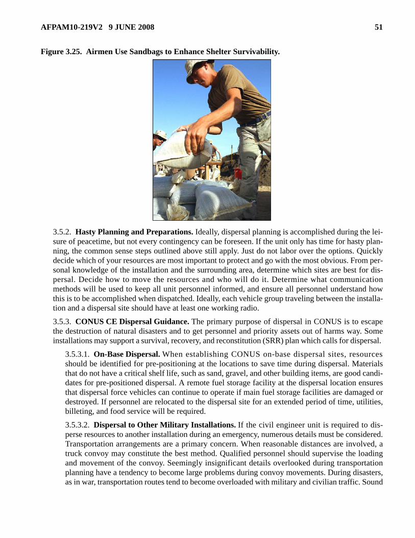
AFPAM10-219V2 9 JUNE 2008 51
Figure 3.25. Airmen Use Sandbags to Enhance Shelter Survivability.
3.5.2. Hasty Planning and Preparations. Ideally, dispersal planning is accomplished during the lei-sure of peacetime, but not every contingency can be foreseen. If the unit only has time for hasty plan-ning, the common sense steps outlined above still apply. Just do not labor over the options. Quicklydecide which of your resources are most important to protect and go with the most obvious. From per-sonal knowledge of the installation and the surrounding area, determine which sites are best for dis-persal. Decide how to move the resources and who will do it. Determine what communicationmethods will be used to keep all unit personnel informed, and ensure all personnel understand howthis is to be accomplished when dispatched. Ideally, each vehicle group traveling between the installa-tion and a dispersal site should have at least one working radio.
3.5.3. CONUS CE Dispersal Guidance. The primary purpose of dispersal in CONUS is to escapethe destruction of natural disasters and to get personnel and priority assets out of harms way. Someinstallations may support a survival, recovery, and reconstitution (SRR) plan which calls for dispersal.
3.5.3.1. On-Base Dispersal. When establishing CONUS on-base dispersal sites, resourcesshould be identified for pre-positioning at the locations to save time during dispersal. Materialsthat do not have a critical shelf life, such as sand, gravel, and other building items, are good candi-dates for pre-positioned dispersal. A remote fuel storage facility at the dispersal location ensuresthat dispersal force vehicles can continue to operate if main fuel storage facilities are damaged ordestroyed. If personnel are relocated to the dispersal site for an extended period of time, utilities,billeting, and food service will be required.
3.5.3.2. Dispersal to Other Military Installations. If the civil engineer unit is required to dis-perse resources to another installation during an emergency, numerous details must be considered.Transportation arrangements are a primary concern. When reasonable distances are involved, atruck convoy may constitute the best method. Qualified personnel should supervise the loadingand movement of the convoy. Seemingly insignificant details overlooked during transportationplanning have a tendency to become large problems during convoy movements. During disasters,as in war, transportation routes tend to become overloaded with military and civilian traffic. Sound

52 AFPAM10-219V2 9 JUNE 2008
convoy procedures should be followed. Close coordination with the receiving installation is essen-tial. The BCE should appoint an experienced person to coordinate billeting and food service sup-port upon arrival at the receiving installation. Communications capabilities should also beassessed to ensure that contact can be maintained with the dispersing force throughout the move-ment and subsequent stay at the dispersal site.
3.5.3.3. Dispersal to Civilian Locations. If a situation arises where this type of dispersalbecomes necessary under peacetime conditions, the BCE must ensure that close coordination isestablished with local property owners and civilian government officials. Approval of the propertyowner must be obtained, and civil engineer personnel must carefully document any property dam-age that occurs as a result of the dispersal. This documentation greatly facilitates the handling ofany claims for reimbursement following the dispersal. If civilian dispersal locations are a reason-able alternative for a CONUS BCE during a peacetime emergency, consider negotiating prior useor rental agreements with civilian property owners or local community officials. Dispersal to civil-ian locations should only be done after careful consideration of on-base and other military basealternatives.
3.5.3.4. Dispersal During Survival, Recovery, and Reconstitution (SRR) Plan Implementa-tion. The SRR plan is intended to improve survival and enhance recovery and reconstitution oper-ations for CONUS air force installations under threat of nuclear attack. Not all CONUS civil engi-neer units have responsibilities under an SRR plan. For those installations that do, the BCE andstaff should carefully review the local SRR plan to determine specific actions required duringimplementation. The general SRR concept of operations during various attack phases follows.
3.5.3.4.1. Attack Preparation Period. If responsibilities have been previously identified,civil engineer forces may be deployed to dispersal installations to support beddown of otherdispersed forces. Additionally, the BCE should send key personnel and equipment to safelocations away from likely target areas so that they are available for recovery operations attheir home installation or at a regroup installation following the attack.
3.5.3.4.2. Attack Response Period. Assuming they are not under direct attack, the activitiesof the dispersed force during this time are concentrated on keeping critical facilities and utili-ties in operation, supporting the deployed force, and maintaining the capability to support theattack recovery mission. Civil engineer personnel may be required to operate emergency elec-trical generators, isolate utilities, and provide other emergency engineer services.
3.5.3.4.3. Attack Recovery Period. During this phase, dispersed civil engineer resources canbe most valuable. These assets may be the only military resources capable of restoring remain-ing installations to an operational status. Reconstitution bases will be designated, and the dis-persed forces will likely be called upon to make any expedient repairs required to accept andbeddown forces deployed or recovering to those installations. The type of work expected fromdispersed forces at this time could range from debris clearance and airfield damage repairs toconstruction of a tent city.
3.5.3.4.4. Civil Resource Requirements. Emergency contractual support and materials willbe required from local sources for rehabilitation of damaged installations or conversion ofcivilian airstrips for military use. For installations with an SRR responsibility, civil engineerresource requirements should be identified and local sources listed for each dispersal or recon-

AFPAM10-219V2 9 JUNE 2008 53
stitution base contemplated for SRR operations. It should be assumed that during wartime con-ditions these resources would be available through emergency requisition.
3.5.4. Overseas CE Dispersal Guidance. An overseas civil engineer uses dispersal as a means ofresource protection for many of the same reasons as a CONUS BCE. In addition, the overseas civilengineer should consider dispersal as a means of protecting resources from CBRNE attacks. Forces atan overseas air base might be dispersed to a remote location on base, to a collocated operating base(COB), or to a civilian location.
3.5.4.1. On-Base Dispersal Locations. Overseas civil engineers, like their CONUS counter-parts, should select locations on the main base which provide optimum protection against anyforeseeable disaster. An area of difference is protection against CBRNE attacks. The overseas airbase is more vulnerable to a CBRNE attack than a CONUS location; therefore, emphasis shouldbe given to selecting multiple dispersal sites removed from the likely target areas of the installa-tion. Dispersal locations removed from prime air base target areas (such as runways, commandand control centers, POL facilities, and munitions storage areas) contribute to the preservation ofresources during an attack. Once these sites have been identified, develop physical protectionmethods for each location as further resource protection. Fire Emergency Services (FES) shouldbe located in close proximity to the operational infrastructure and should be given special consid-eration for dispersal locations, concealment, and physical protection.
3.5.4.2. COB Dispersal Locations. A COB is an allied installation that can be used to beddownaugmenting forces. Close coordination with the host installation agencies is a primary requirementduring any dispersal to a COB. An important aspect of dispersal to a COB is the cultural, proce-dural, and language differences that civil engineer personnel must overcome.
3.5.4.3. Dispersal to Civilian Locations. Dispersal to a civilian location in an overseas environ-ment is much more complicated than it would be in a CONUS area. The laws of each country dif-fer, and there may be no existing status-of-forces agreements for obtaining rights to use localproperty as a dispersal site. Again, the base must evaluate needs and determine if off-base dis-persal sites would serve a useful purpose. If these sites are determined to be necessary, discuss thepossibility of negotiated agreements with the base legal staff, your MAJCOM, and representativesof the host government. Negotiations with foreign property owners are best left to members of thehost government.
3.5.5. Summary. Temporary dispersal is a relatively inexpensive and expedient method to protectimportant installation assets from the effects of disasters and enemy attack, but some advance warningis required to mobilize personnel and assets. The value of wartime dispersal can be improved byemploying supplemental protection and hardening measures. For information on specific dispersalcriteria and procedures, refer to the reference documents in Table 3.5.
54 AFPAM10-219V2 9 JUNE 2008
Table 3.5. Dispersal References.
3.6. Antiterrorism Measures. Antiterrorism measures help ensure adequate protection of personnel andassets critical to air base operations. Although, the installation Force Protection Working Group (FPWG)or Antiterrorism Officer (ATO) identifies appropriate force protection and antiterrorism requirements,civil engineers also play an important role in the planning, design, and development of antiterrorism andforce protection measures. For more specific actions to increase a facility’s physical and passive protec-tion against terrorist activities, see AFI 10-245, Air Force Antiterrorism (AT) Standards, and the referencedocuments listed in Table 3.6.
Table 3.6. Antiterrorism References.
3.7. CBRN Passive Defensive Measures. If an adversary succeeds in launching a CBRN attack andactive defense measures fail to eliminate the delivery vehicle and/or weapons, passive defense will beessential. Civil engineers play a prominent role in CBRN passive defense. Passive defensive measures aredesigned to improve the capability of personnel to survive and sustain operations in CBRN environmentsand are organized into four capability areas: sense, shape, shield, and sustain.
Other Dispersal References AFPAM 10-219, Volume 3, Postattack and Postdisaster Procedures. AFPAM 10-219, Volume 5, Bare Base Conceptual Planning Guide. AFH 10-222, Volume 1, Guide to Bare Base Development. AFH 10-222, Volume 3, Guide to Civil Engineer Force Protection. AFMAN 10-2602, Nuclear, Biological, Chemical, and Conventional (NBCC) Defense Operations and Standards. UFC 3-260-01, Airfield and Heliport Planning and Design. UFC 3-340-01, Design and Analysis of Hardened Structures to Conventional Weapons Effects. UFC 4-010-01, DOD Minimum Antiterrorism Standards for Buildings. Joint Forward Operations Base (JFOB) Force Protection Handbook (to be replaced by UFC 4-027-01, Design of Deployed Operational Bases to Mitigate Terrorist Attacks).
Other Antiterrorism References AFPAM 10-219, Volume 3, Postattack and Postdisaster Procedures. AFH 10-222, Volume 3, Guide to Civil Engineer Force Protection. AFH 10-222, Volume 14, Guide to Fighting Positions, Obstacles, and Revetments. UFC 4-010-01, DOD Minimum Antiterrorism Standards for Buildings. UFC 4-021-01, Design and O&M: Mass Notification Systems. UFC 4-022-01, Entry Control Facilities/Access Control Points. Joint Forward Operations Base (JFOB) Force Protection Handbook (1 May 2008) (to be replaced by UFC 4-027-01, Design of Deployed Operational Bases to Mitigate Terrorist Attacks).
AFPAM10-219V2 9 JUNE 2008 55
3.7.1. Sense. Sense activities provide commanders with up-to-date information on CBRN threats bydetecting, identifying, and qualifying/quantifying hazards. Obtaining this information requires accu-rate assessments in a number of areas to include sampling, detection, and identification. CBRN detec-tion, sampling, and identification are multifaceted and multifunctional operations and include CBRNpoint and standoff detection systems; medical, food, and water surveillance; and attack preparationand Post Attack Reconnaissance (PAR) for unexploded explosive ordnance by unit and installationPAR teams. Point detection systems continue to improve and incorporate rapid identification capabil-ities. Epidemiological surveillance conducted by public health and medical personnel also contributesto detecting biological weapons exposure, low-level chemical agent exposure (below current instru-ment detection levels), and radiation exposure. Airmen also serve as a key component of the sensingarchitecture. They should be trained to sense indications of impending or actual CBRN attacks, reportthose indications, and take the immediate and prudent actions necessary to protect themselves andmission resources.
3.7.2. Shape. Shaping is the characterization of CBRN hazards to accurately describe the current andfuture operational picture to the commander. Passive defense activities that allow a commander toshape the operational environment include CBRN effects predictions, meteorological conditionassessments, gaining situational awareness and predicting future events, establishing protected bed-down locations to mitigate CBRN effects, and identifying health risks to ensure a fit and healthy fight-ing force. Intelligence, civil engineering, and weather experts provide predictions on the nature of thethreat. For meteorological condition assessments, weather experts supply information on terrain,weather conditions, and other meteorological data, while CE readiness CBRN experts provide accu-rate predictions about the type of agent, release point, and the plume (footprint of the contaminatedarea).
3.7.3. Shield. Shielding includes protecting forces from harmful effects and hazards of CBRNthreats. Shielding may be accomplished through activities to prevent, mitigate, and minimize CBRNexposure effects (including the administration of vaccines and prophylaxis) or through contaminationavoidance to prevent or reduce exposures. Passive defense activities which allow a commander toshield warfighting forces include disease and casualty prevention, contamination avoidance, contami-nation control, and protective countermeasures. Disease and casualty prevention includes steps takento prevent casualties before attack and to minimize casualties after a CBRN attack. Contaminationavoidance includes actions taken to minimize the impact of CBRN attacks by eliminating exposure tocontamination. While operating in a CBRN environment, contamination control prevents secondarytransfer of disease and chemical, biological or radiological material and/or re-aerosolization of anagent. Contamination control includes avoiding, reducing, removing, or rendering harmless the haz-ards from CBRN contamination.
3.7.4. Sustain. Sustainment activities enable the commander to sustain operations or facilitate thereturn to operational capability as soon as possible. These activities include identifying hazardousareas through PAR, notifying personnel, and decontaminating and managing casualties, as needed.Decontamination and health risk assessments are important first steps toward a return to operationalcapability. Effective decontamination operations help sustain or enhance the flow of operations bypreventing or minimizing performance degradation, casualties, or loss of material (Figure 3.26.).

56 AFPAM10-219V2 9 JUNE 2008
Figure 3.26. Effective Decontamination Prevents Casualties.
3.7.5. Other Passive Defensive Measures. Installation CBRN defense actions should focus onattack detection and warning, protection, and mitigation of specific threats and threat weapon systems.Although not all inclusive, Table 3.7. list a few examples of passive defensive measures that installa-tions may take. See Air Force Doctrine Document (AFDD) 2-1.8, Counter-Chemical, Biological,Radiological, and Nuclear Operations, and AFMAN 10-2602 (until rescinded by AFMAN 10-2502Series publications) for more information on CBRN passive defensive measures.

AFPAM10-219V2 9 JUNE 2008 57
Table 3.7. Typical Installation CBRN Passive Defensive Measures.
CBRN Passive Defensive Measures and Specific Actions Review threat levels, warning signals, and alarm conditions: Provide visual aids and current information to each unit control centers, the base population, and all assigned, attached, coalition, and host-nation forces.
Develop multilingual visual aids and public address systems announcements.
Include warning procedures for geographically separated units, non-combatants, and enemy prisoners of war. Verify the operation and coverage of the installation warning system: Verify the actual times required to notify the air base population under each warning method (base siren, public address system, radio net, and telephone).
Verify the warning system is able to provide warning and notification to 100 percent of the air base population within 10 minutes. Implement the air base zones or sector plan to support the movement of contaminated assets (people and equipment) between zones or sectors: Identify critical attack recovery teams (explosive ordinance disposal (EOD), airfield and building damage assessment, CBRN reconnaissance, and firefighter) and sector or zone crossing procedures to facilitate quick movement in support of recovery operations.
UCCs must ensure that personnel moving from contaminated zones or sectors to uncontaminated zones or sectors do not inadvertently reduce MOPP when split-MOPP operations are executed. Review the status of planned and in-progress medical pretreatments. Develop and implement an air base Ground Sector and CBRN zone plan: Practice likely attack recovery scenarios with command and control elements.
Ensure unit control centers understand their responsibility to maintain control of their personnel when they enter or exit contaminated areas.
Provide zone or sector information or maps to each unit control center and all assigned, attached, coalition, and host-nation command and control centers. If the previous alarm condition was Alarm Red or Black, re-evaluate the status of protective actions:

58 AFPAM10-219V2 9 JUNE 2008
3.8. Base Evacuation. Evacuation of personnel and key resources is often accomplished to preventinjury and minimize damage and destruction. Limited area evacuations are usually conducted for reasonssuch as accidents, criminal activity, terrorist attacks, and other localized incidents. However, base evacu-
Replenish material expended during contamination control or decontamination operations.
Redistribute material, such as IPE and nerve agent antidotes, to support priority missions or units with high usage rates.
Take action to replace casualties.
Review previously reported damage. Verify damage, contamination, and UXO reports were received and action is complete or under way to resolve the situation.
Initiate action to collect and dispose of contaminated waste, unclaimed weapons and ammunition, and UXO that is declared safe for movement to holding areas.
Prepare a written record that identifies the location of previously contaminated areas, unrecovered human remains, contaminated waste burial sites, missile and bomb craters, and unrecovered UXO. Review the probable CBRN attack threat scenarios and actions with Security Forces, CE Readiness and Emergency Management, and intelligence personnel at each shift change. Activate CBRN specialized teams: Assign personnel where needed to bring teams up to 100 percent of required manning for 24-hour operations.
Direct responsible units to verify team material is serviceable and operators are proficient.
Conduct team drills and training to meet local proficiency standards. Maintain watch for clandestine attack indications Periodically remind personnel to remain observant for signs of a clandestine or suspicious activity. Provide specific information on threats, if available.
Increase protection for food and water supplies.
Direct units to store a 24-hour supply of Meals, Ready to Eat (MREs) in their unit area. If attacks have occurred, consider the need to use uncontaminated MREs or packaged foods and bottled water until food service supplies are checked for contamination. Develop or implement the air base CCA plan: Identify primary and alternate CCA on-base locations.
CCA must be able to process the required percentage of the air base population over a 24-hour period.
CBRN Passive Defensive Measures and Specific Actions

AFPAM10-219V2 9 JUNE 2008 59
ations are large-scale relocations typically implemented for natural disasters and non-combatant evacua-tion operations (NEO) prior to an enemy attack. Since specific CE execution tasks for base evacuationsare different for each installation, mission, situation, and location, follow instructions in the base CEMP10-2 and CE CRP. In addition to coordinating on-base evacuation plans, general CE preparations for baseevacuations include the following:
3.8.1. Natural Disasters. Develop unit procedures to disseminate and execute base evacuationorders and information. Also develop unit evacuation plans to include vehicle load plans.
3.8.2. Non-Combatant Evacuation (NEO) Prior to Enemy Attack. Develop facility use and siteplans to beddown incoming non-combatant evacuees.

60 AFPAM10-219V2 9 JUNE 2008
Chapter 4
COMMUNICATIONS SYSTEMS
4.1. Introduction. Managing and controlling information effectively are paramount in any coordinatedactivity—this is especially true during military and disaster response operations. Command and controlcenters are virtually worthless without good communications. A key part of civil engineer preparationsfor disaster and attack includes working with the communications squadron to ensure key communicationnodes are in place and operational. These nodes include: primary and secondary installation warning sys-tems (e.g., Giant Voice and Telephone Alerting Systems); primary and secondary crash networks; andcommunications nodes for the primary and alternate Installation Control Center (ICC), Emergency Oper-ations Center (EOC), CE Damage Control Center (DCC), Base Defense Operations Center (BDOC), FireAlarm Communications Center (FACC), and the Emergency Communications Center (consolidated dis-patch) when implemented. Civil engineers also accomplish other command and control preparations suchas setting up the DCC and EOC facilities and establishing manual procedures for collecting informationon damage to facilities, utilities, and pavements when disruptions in installation communications andcomputer systems occur.
4.2. Communications Systems. Communications systems are a primary means of command and con-trol. They are used in every aspect of C2, including planning, directing, coordinating, and controllingforces and operations in the accomplishment of the mission. Although the discussion in this sectionfocuses on communications systems that are used in the EOC and DCC, several of the communicationsmethods addressed here could apply to any unit control center (UCC).
4.2.1. Emergency Operations Center (EOC). The EOC is the C2 support element that directs,monitors, and supports the installation’s actions before, during, and after an incident, attack, or disas-ter. The EOC updates the ICC with ongoing incident status and seeks support through the ICC whenon-scene requirements surpass the installation’s inherent capability. Each method of communicationlisted below fulfills a unique requirement, and each has its own limitations. There is no specific stan-dard, but a well-equipped EOC will have the following:
4.2.1.1. Telephones. Preferably one multi-line unit is provided at each work station. Prepare a listwith phone numbers of key personnel and frequently called organizations. Include counterpartsfor joint operations and local communities (i.e., local EOC). Remember that non-secure tele-phones can be monitored, and lines can be easily cut.
4.2.1.2. Intra-Base Radios. Radios should be capable of communicating on all frequencies asso-ciated with disaster and wartime response. These frequencies include emergency management,FES, EOD, CE, security forces, vehicle operations/dispatch, etc. Equip the radios with speakersand headsets. The headsets help reduce the noise level in the EOC while the speakers permiteveryone to listen when required. Older radio systems may have only one frequency. Those radiosare easily jammed and monitored. When a lot of personnel need to use one frequency, your ownpersonnel tend to jam each other. These problems can be reduced by using the secure, multi-fre-quency Scope Shield II radios.
4.2.1.3. Tactical Radios. These radios are required to communicate with the mobile emergencyoperations center.

AFPAM10-219V2 9 JUNE 2008 61
4.2.1.4. Hot Lines. These provide a direct line to the ICC and UCC. Hot lines are useful betweenfunctional representatives in the EOC and their UCCs. While a little slower and subject to busysignals, telephones can do this job.
4.2.1.5. Installation Public Address System. Access to a public address system, such as GiantVoice, gives the EOC a method to pass time-sensitive threat warning conditions to the base popu-lation, but it is one-way communication only.
4.2.1.6. FAX Capability. FAX machines are an increasingly useful method of quickly transmit-ting information. While one machine in a control center is sufficient, identify a backup machine orone that can be relocated to the EOC.
4.2.1.7. Cellular Phones. These phones significantly expand the communication options in theUS. This area continues to improve, both in the US and overseas. They are especially useful indisaster situations.
4.2.1.8. Field Telephones. When nothing else is available, field phones can be a blessing. How-ever, you must run wires between the phones, and that takes time. You will also need to protect thewires from accidental breaks especially near vehicle traffic routes. Not many installations havethese phones on-hand, because other communication methods are convenient and readily avail-able.
4.2.1.9. Computers. Computers facilitate the quick transfer of data and other informationbetween the EOC, ICC, and unit control centers, significantly reducing the time and errorsinvolved versus passing information by telephone or radio. Computers typically replace visiblestatus charts, store additional status and damage assessment information, and eliminate the needfor paper copies of damage assessment reports. Computers should be pre-loaded with installationmaps, status charts, plans, checklists, etc. Maps can be loaded so the user can zoom into any loca-tion for additional detail, which is especially useful with accurately mapped utility systems. TheGuardian Installation Protection Program is introducing linked computers which connect the IC tothe EOC wirelessly, allowing digital photos and other real-time data from the scene to be providedto the EOC. However, wireless communications and some other uses can present firewall prob-lems which must be worked out in advance with your local communications squadron.
4.2.1.9.1. Four conditions should be satisfied before you rely on computers in or between con-trol centers: each key person in any control center should have easy access to a computer, thecomputers should be networked so the status information can be shared, the server should beprotected from damage, and the computers must have secure power. You cannot afford to losethe information or lose access to it.
4.2.1.9.2. Be sure to safeguard classified checklists, plans, and other materials stored in indi-vidual computers or transferred over a network.
4.2.2. CE Damage Control Center (DCC). Normally manned by CE specialists from infrastructuresupport, heavy repair, facility maintenance, and other engineering fields, the DCC controls and com-municates CE response activities, coordinates those activities with other base organizations, andarranges support from others as needed. Communications equipment within the DCC facility nor-mally includes telephones, hot lines, radios, and other communication devices.
4.3. Installation Notification and Warning System (INWS). The INWS is a combination of methodsusing audible and visual signals, verbal messages, and electronic communication. Communication modes

62 AFPAM10-219V2 9 JUNE 2008
include sirens, horns, radio tone alerting, mass notification systems, unaided voice systems, public andbroadcast address systems, local area network messaging, telephone alert conferencing, pagers, televi-sion, radio, flags, signs, and other electronic or mechanical methods. The design of these warning systemsis usually a collaboration between CE and communications squadrons, and the systems are required to beredundant, hardened, or splinter-protected and operate using both commercial and emergency power.Existing networks should also be incorporated into this system. Other features of the INWS are listed inTable 4.1.
Table 4.1. INWS Features.
4.3.1. Mass Notification System (MNS). Implementation of an effective mass notification systemrequires the coordinated efforts of engineering, communications, and security personnel. Coordina-tion with communications personnel is needed because every mass notification system will require theuse of base communication systems. Each installation should prepare an implementation plan thatestablishes a comprehensive approach to mass notification that is acceptable to security, communica-tions, and engineering personnel. Elements of an implementation plan include a needs assessment,requirements definition, alternatives evaluation, system selection, and implementation schedule. Massnotification systems include individual building systems, giant voice system, and telephone alertingsystem.
4.3.1.1. Individual Building Systems. These systems consist of the Autonomous Control Unitand Notification Appliance Network.
4.3.1.1.1. Autonomous Control Unit. The autonomous control unit is used to monitor andcontrol the notification appliance network and provide consoles for local operation. Using aconsole, personnel can initiate, in a building, the delivery of pre-recorded voice messages, pro-vide live voice messages and instructions, and initiate visual strobe and (optional) textual mes-sage notification. The autonomous control unit will temporarily deactivate audible fire alarmappliances while delivering voice messages to ensure the messages are intelligible. If an instal-lation-wide control system for mass notification is provided on the installation, the autono-mous control unit also communicates with the central control unit of the installation-widesystem to provide status information and receive commands and messages.
4.3.1.1.2. Notification Appliance Network. The notification appliance network consists ofaudio speakers located to provide intelligible instructions in and around the building. Strobesmay also be provided to alert hearing-impaired occupants.
Installation Notification and Warning System Provide installation-wide coverage of outdoor areas, indoor facilities, housing, and separated sites. Reach off-base facilities that are controlled or owned by the installation to ensure coverage for personnel working or billeted in those areas. Incorporate DOD-required Mass Notification System (MNS) into the indoor coverage. Incorporate systematic and coordinated standard to support the Air Force Incident Management System(AFIMS). Provide mechanisms for vertical and horizontal coordination, communications, and information sharing in response to threats or incidents.

AFPAM10-219V2 9 JUNE 2008 63
4.3.1.2. Giant Voice System. The Giant Voice System (Figure 4.1.), also known as Big Voice, istypically installed as an installation-wide system to provide a siren signal and pre-recorded andlive voice messages. It is most useful for providing mass notification for personnel in outdoorareas, expeditionary structures, and temporary buildings. It is generally not suitable for mass noti-fication to personnel in permanent structures because the voice messages are generally unintelligi-ble. If an installation-wide control system for mass notification is provided on the installation, aninterface to the Giant Voice system may improve the functionality of both systems.
Figure 4.1. Engineers Install Giant Voice System at Deployed Location.
4.3.1.3. Telephone Alerting System. Telephone alerting systems are independent systems thatmay be used to provide mass notification to buildings and facilities. These systems are useful forbuildings in which notification to all building occupants may not be appropriate (e.g., child devel-opment centers, hospital patient areas, brigs). They also might be appropriate for small facilitiesand military family housing where mass notification is not required by UFC 4-010-01. Use of tele-phone alerting systems, however, should be considered carefully before installing in most build-ings and facilities requiring mass notification because there are many limitations in deliveringnotification messages by telephone.
4.3.2. INWS Summary. Every Air Force installation is required to have a rapid and effective systemto disseminate emergency information quickly, but every installation does not have an installationnotification and warning system with all the elements and methods described in this section. Never-theless, any system, procedures, or combination thereof that provides required mass notification capa-bility may be acceptable. Refer to AFI 10-2501 and UFC 4-021-01 for details on notification andwarning standards.
4.4. Other Command and Control Preparations. In addition to helping with EOC communicationsand the installation’s mass notification and warning system, civil engineers have the added tasks of settingup and managing the installation primary EOC, mobile emergency operations center (MEOC), and CEunit control center and completing other C2 preparations. These other command and control preparations

64 AFPAM10-219V2 9 JUNE 2008
involve setting up facilities, organizing control center teams; putting communications equipment and pro-cedures in place; publishing base alert conditions and alarm signals; establishing control center operatingprocedures; developing unit procedures for recall, authentication codes, and passwords; and making pro-visions for continuity of operations. The composition of the EOC and the functional relationships with theinstallation control center and unit control centers are addressed in AFI 10-2501.
4.4.1. EOC Facility. Ideally the EOC should be located adjacent to or collocated with the installationcontrol center; however, some EOCs are located in separate facilities and still operate effectively. In ahigh-threat area, the EOC should be semi-hardened or at least splinter protected to improve its surviv-ability. Be sure to provide backup electrical power or a connection for quick hookup of an emergencygenerator. On the inside, arrange work stations so emergency support function (ESF) personnel haveeasy access to view maps, situation status information, and the Common Operating Picture and cancommunicate easily with each other and the EOC director (Figure 4.2.).
Figure 4.2. Typical ESF Work Station Arrangement.
4.4.1.1. Maps. Typical maps that should be provided are listed in Table 4.2. The airfield pave-ments map is most often used in wartime to plot damage and repairs to the airfield pavements.
Table 4.2. Map Types and Scale.
4.4.1.2. Incident Status Displays. In addition to maps, readily visible status displays (usuallyelectronic or status boards) help the EOC staff keep track of the condition of the installation, unitstatus, and the recovery efforts. Suggested incident status displays include those listed in Table4.3.
Map Type Scale On-Base Crash Grid Map 1:4800 or 1:2400 (suggested) Off-Base Grid Map 1:250,000 (approximately) Area CBRN Map 1:250,000 (approximately) Base CBRN Map 1:50,000 (or smaller) Airfield Pavements Map 1:1200 (suggested)

AFPAM10-219V2 9 JUNE 2008 65
Table 4.3. Incident Status Displays.
4.4.2. CE Damage Control Center. The best place for the CE Damage Control Center (DCC) iswithin walking distance of the CE shops. This makes communications easier when phones or radiosare not available. Install a backup power source. As with the EOC, appropriate maps of the facility andairfield should be readily available for coordinating and plotting response activities (Figure 4.3.). SeeAFPAM 10-219, Volume 1, for staffing recommendations.
Figure 4.3. Civil Engineer DCC Facility.
4.4.2.1. OPLANs and Support Plans. Keep at least one copy in the DCC of every operationsplan (OPLAN), support plan, or base plan that CE supports. There should be multiple copies of theCE Contingency Response Plan. Table 4.4. lists three examples of plans that should be maintainedin the DCC when needed.
Incident Status Information/Data Alert Condition/Defense Condition/Air Raid Status NUDET (Nuclear Detonation) Board MOPP Analysis Chemical Downwind Message Status Shelter Status Unit Status, Including Manpower Facility/Utility System Damage Status Casualty Status Generator Status Aircraft Arresting Systems Status

66 AFPAM10-219V2 9 JUNE 2008
Table 4.4. Support Plans and Their Purpose.
4.4.2.2. Maps. Nothing is as useful as a good map to help maintain a “picture” of the crisis andyour response. Place maps in frames and cover with Plexiglas so the maps can be easily marked upand cleaned off. Light the maps, but do it so glare is not a problem. Use these maps:
4.4.2.2.1. On-base crash grid map (1:4800 scale - 1” = 400′)
4.4.2.2.2. Off-base crash grid map.
4.4.2.2.3. Airfield pavements or takeoff and landing (TOL) surfaces map (1:1200 scale - 1” =100′) with runway/taxiway station marking systems annotated.
4.4.2.2.4. Master plan tabs (G-tabs) - utility systems. The suggested scale is 1” = 400′. If nec-essary at big bases, use 1” = 600′ or 1” = 800′. (If they exist, keep a set of the smaller scale(1:1200 - 1” = 100′ or 1:600 - 1” = 50′) tabs for each utility. These are usually too large tomount on the wall.)
4.4.2.2.5. Use geospatial site-mapping information, services, and overlays, when available.
4.4.2.3. Status Charts. Maintain visible status charts (Table 4.5.) to help control the CEresponses to a crisis. Display these charts and any others that you may find helpful. Attachment 2contains some ideas for status chart formats.
Plan Type Purpose Comprehensive Emergency Management Plan (CEMP) 10-2
Provides comprehensive guidance for emergency response to physical threats resulting from major accidents, natural disasters, conventional attacks, terrorist attacks, and CBRN attacks.
CE Contingency Response Plan (CRP) with all annexes and checklists.
This plan is the civil engineer's detailed guide for using and controlling the engineer forces in a disaster or contingency at an installation. This plan should provide CE-specific guidance for supporting implementation of CEMP 10-2 and other base-level plans.
HAZMAT Emergency Planning and Response Plan
Outlines how the base responds to a spill of hazardous materialsother than nuclear and explosives. Base Civil Engineer isresponsible for the HAZMAT Plan; however, it requires the activesupport of many base organizations.

AFPAM10-219V2 9 JUNE 2008 67
Table 4.5. DCC Status Charts.
4.4.2.4. Communications. Provide good communications equipment for the DCC staff. As withthe EOC, install telephones, intra-base radios, and FAX capability. Use cellular phones when pos-sible, and consider field telephones. Radios in the DCC should be equipped with both speakersand headsets. The DCC should be connected with the functions, units, and teams listed in Table4.6. Try to establish two independent methods. Practical connections are offered, but any methodyou choose is okay.
4.4.2.4.1. Call Signs. Set up call signs for CE shops or teams. At home station, use codes younormally use in peacetime. This reduces confusion. At deployment locations, find out the localCE frequencies and call signs. When starting from scratch, consider functional call signs, suchas Electrical-1, 2, 3; Structures-1, 2, 3; Pavements-1, 2, 3, or with humorous but descriptivenames such as Sparky-1, 2, 3; Hammer-1, 2, 3; Dirtboy-1, 2, 3.
4.4.2.4.2. Unit Recall. Develop procedures to recall members of the CE unit to duty stationsduring non-duty periods. The most common method is the telephone pyramid recall, but run-ners can be used. Keep recall and assembly instructions simple, and train unit personnel inadvance on where to report and with what. Have procedures to recall the entire unit and justthe military. Review those procedures for possible adjustment when a Prime BEEF teamdeploys. When normal telephone communications are not available, preplanned and testedalternate procedures must be ready for use.
Sample Status Charts Personnel status—key personnel/team and shift assignments/accountability by Air Force Specialty (AFS)/casualty status.
Alert condition/defense condition/air raid warning condition/threat condition/natural disaster threat condition/MOPP condition.
Aircraft arresting system status. Utility systems status. Generator status. ADR status. Vehicle status. CE radio call signs and frequencies. Special purpose equipment status. Priority facility damage/recovery status. Critical supplies and spares status. Critical infrastructure status.

68 AFPAM10-219V2 9 JUNE 2008
Table 4.6. DCC Communication Methods.
4.4.2.5. Other Items to Have On Hand. There are a number of other items which are useful tohave on hand in the DCC. Some of them are:
4.4.2.5.1. AFPAM 10-219 series publications.
4.4.2.5.2. AFH 10-222 series handbooks.
4.4.2.5.3. MOS (minimum operating strip) selection templates (at bases subject to an enemyattack).
4.4.2.5.4. T.O. 35E2-4-1, Repair Quality Criteria System for Rapid Runway Repair (at basessubject to an enemy attack).
4.4.2.5.5. Local area telephone directory with yellow pages.
4.4.2.6. Computers. Computers can also be put to good use in the DCC. The thoughts on usingcomputers in the EOC also apply to the DCC.
4.4.3. Alternate Communications Procedures. Plan and practice Comm-out/radio silence proce-dures. In a crisis, count on losing communications with someone or some organization. Also, theremay be situations where you want to impose radio silence. In either case, develop alternate methods topass information. If you lose a base station, a vehicle with a radio can be positioned nearby or just theradio with a battery can be used. Most likely you must use other radios in between your destination torelay the messages. Runners are also effective, but slower.
4.4.3.1. Arrange for runners. Runners are a reliable way to pass lengthy, detailed data, but they arealso the slowest form of communication. While not an absolute rule, it is a good idea to identifythese personnel in advance. Show runners where they must go and how to get there, because somewill have a poor knowledge of the installation and a poor sense of direction.
4.4.3.2. Arrange for visual signals such as flags and flares. These methods can quickly send sim-ple alert signals to personnel within visual range when radios are not available.
Function Sample Communication Methods Installation Control Center Telephone / FAX / Runners EOC and alternate EOC Hot line / Telephone / Radio / FAX / Cellular Phone /
Runners / Field Phone Alternate DCC (if there is one) Hotline / Telephone / Radio / FAX / Cellular Phone /
Runners / Field Phone CE Response and Repair Teams Radio / Cellular Phone / Runners CE Shelters Telephone / Radio / Cellular Phone / Field Phone /
Runners Fire Alarm Control Center (FACC) Telephone / Radio / Hot Line Base Defense Operations Center (BDOC) and Alternate BDOC
Telephone / Radio
Hospital Telephone Other Installation units Telephone
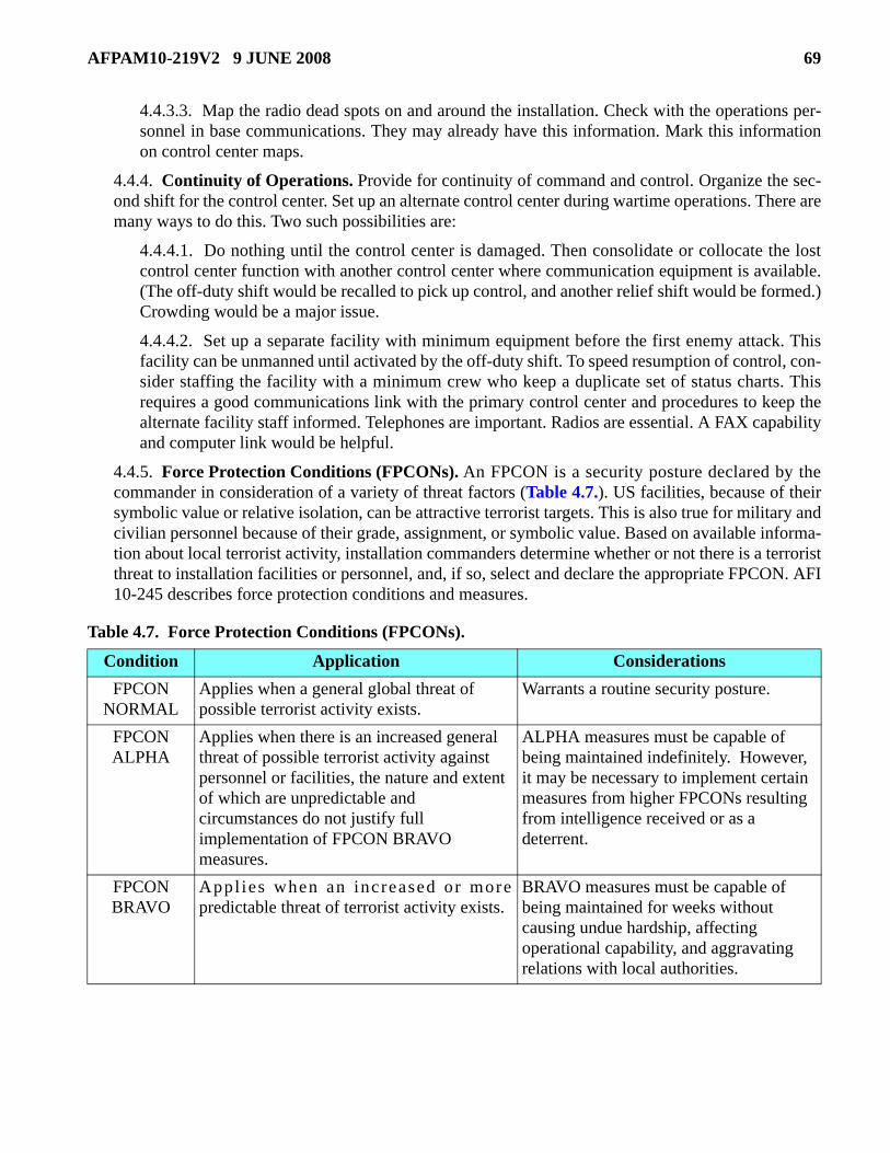
AFPAM10-219V2 9 JUNE 2008 69
4.4.3.3. Map the radio dead spots on and around the installation. Check with the operations per-sonnel in base communications. They may already have this information. Mark this informationon control center maps.
4.4.4. Continuity of Operations. Provide for continuity of command and control. Organize the sec-ond shift for the control center. Set up an alternate control center during wartime operations. There aremany ways to do this. Two such possibilities are:
4.4.4.1. Do nothing until the control center is damaged. Then consolidate or collocate the lostcontrol center function with another control center where communication equipment is available.(The off-duty shift would be recalled to pick up control, and another relief shift would be formed.)Crowding would be a major issue.
4.4.4.2. Set up a separate facility with minimum equipment before the first enemy attack. Thisfacility can be unmanned until activated by the off-duty shift. To speed resumption of control, con-sider staffing the facility with a minimum crew who keep a duplicate set of status charts. Thisrequires a good communications link with the primary control center and procedures to keep thealternate facility staff informed. Telephones are important. Radios are essential. A FAX capabilityand computer link would be helpful.
4.4.5. Force Protection Conditions (FPCONs). An FPCON is a security posture declared by thecommander in consideration of a variety of threat factors (Table 4.7.). US facilities, because of theirsymbolic value or relative isolation, can be attractive terrorist targets. This is also true for military andcivilian personnel because of their grade, assignment, or symbolic value. Based on available informa-tion about local terrorist activity, installation commanders determine whether or not there is a terroristthreat to installation facilities or personnel, and, if so, select and declare the appropriate FPCON. AFI10-245 describes force protection conditions and measures.
Table 4.7. Force Protection Conditions (FPCONs).
Condition Application Considerations FPCON
NORMAL Applies when a general global threat of possible terrorist activity exists.
Warrants a routine security posture.
FPCON ALPHA
Applies when there is an increased general threat of possible terrorist activity against personnel or facilities, the nature and extent of which are unpredictable and circumstances do not justify full implementation of FPCON BRAVO measures.
ALPHA measures must be capable of being maintained indefinitely. However, it may be necessary to implement certain measures from higher FPCONs resulting from intelligence received or as a deterrent.
FPCON BRAVO
Appl ies when an increased or morepredictable threat of terrorist activity exists.
BRAVO measures must be capable of being maintained for weeks without causing undue hardship, affecting operational capability, and aggravating relations with local authorities.

70 AFPAM10-219V2 9 JUNE 2008
4.4.6. Emergency Notification and Alarm Signals. Emergency notification and alarm signals warnbase personnel and units of an attack or impending disaster. The more advance warning given, thegreater the probability that advance actions can reduce damage and injury. Everyone on base shouldknow the meaning of each signal. Signals may be passed by sirens, horns, flags, telephone, intra-baseand tactical radios, stationary and mobile public address systems, whistles, person-to-person, televi-sion, radio, etc. The methods used depend on the nature and immediacy of the crisis, location of per-sonnel to be notified, and alerting systems available. Signals may be repeated as often as necessary tomake sure that the entire base population responds. The Air Force has standard emergency notifica-tion and alarm signals which are described in two visual aids: AFVA 10-2510, U.S. Air Force Emer-gency Notification Signals, and AFVA 10-2511, USAF Standardized Attack Warning Signals forNBCC Medium and High Threat Areas, as shown in AFMAN 10-2602 (until rescinded by AFMAN10-2502 Series publications). Additional signals may be used to meet the peculiar needs of any com-mand or installation. Installations in overseas areas use the signals prescribed by the unified theatercommander.
4.5. Summary. Sound command and control preparations facilitate coordination, communications, andcooperation between agencies and personnel during an emergency. They also improve base response,recovery, and mission sustainment. For more specific information on CE preparations related to com-mand, control, and communications, review the references listed in Table 4.8.
Table 4.8. C2 and Communications Preparations References.
FPCON CHARLIE
Applies when an incident occurs or intelligence is received indicating some form of terrorist action or targeting against personnel or facilities is likely.
Implementation of CHARLIE measures for more than a short period probably will create hardship and affect the activities of the unit and its personnel.
FPCON DELTA
Applies in the immediate area where a terrorist attack has occurred or when intelligence has been received that terrorist action against a specific location or person is imminent.
Normally, this FPCON is declared as a localized condition.
C2 and Communications Preparation References AFI 10-245, Air Force Antiterrorism (AT) Standards. AFI 10-2501, Air Force Emergency Management (EM) Program Planning and Operations. AFPAM 10-219, Volume 1, Contingency and Disaster Planning. UFC 4-021-01, Design and O&M: Mass Notification Systems. UFC 4-010-01, DOD Minimum Antiterrorism Standards for Buildings. Joint Forward Operations Base (JFOB) Force Protection Handbook (to be replaced by UFC 4-027-01, Design of Deployed Operational Bases to Mitigate Terrorist Attacks).
Condition Application Considerations

AFPAM10-219V2 9 JUNE 2008 71
Chapter 5
ISOLATION, BACKUP, AND PROTECTION OF UTILITIES
5.1. Introduction. The loss of utility service has immediate impacts on the operations of an air base.Some losses cause only annoyance or inconvenience, but others quickly degrade mission performance.The significance of those impacts varies with the utility that has been disrupted, the nature and extent ofthe disruption, and the importance of the affected activities to the mission. As “owner” of the base utilitysystems, civil engineers can minimize utility service disruption and resulting mission impacts with gooddisaster attack planning and preparations. As a minimum, civil engineers should ensure that proceduresand resources are in place to isolate all or portions of the base utility systems, provide utility backup tomission-critical activities, and protect key components of the utility systems from damage. For situationswhen only limited utility service can be provided, the base must also develop demand reduction proce-dures. Protecting important base utility services is not a CE-only responsibility. Many preparationsrequire installation-wide inputs and preplanned responses. This chapter presents recommendations fordeveloping system isolation; emergency backup; and physical protection measures in each of seven utilitysystems: electrical, water, heating, gas, liquid fuels, sanitary sewage, and airfield lighting. The importanceof installation-wide demand reduction procedures is also highlighted.
5.2. Learning the Systems. The first step in disaster or attack preparation of a utility system is to learnall you can about that system: its sources, configuration, vulnerabilities, operating details, recurring prob-lems, spare parts, and other basic utility data. If possible, use Expeditionary Site Mapping to aid in iden-tifying and locating critical equipment or resources. When searching for utility information, a good datasource is the Base Comprehensive Plan. This plan is a combination of component plans, studies, and mapsthat document a wide range of information that is essential to decision-makers when planning and manag-ing an installation’s physical assets in support of the mission. The Infrastructure Component Plan and tabsE and G are part of the Base Comprehensive Plan and are good sources of information for successful plan-ning of isolation procedures and other utility system preparations. Attachment 4 is a comprehensive planmap that lists the titles of all associated tabs.
5.2.1. Basic Utility Data. This paragraph outlines, in general terms, the information you should col-lect for all utility systems on your installation. You can find suggestions for utility-specific informa-tion in paragraph 5.5. through 5.11. Include systems information in the utilities annex (N) of your CEContingency Response Plan. For most installations, data collection is an easy task because informa-tion should already be available. Good shop foremen have this information on hand, because they useit in their day-to-day activities. Civil engineers need to gather this information and put it in one place,because “the person with the needed information” may not always be available.
5.2.1.1. Source/Treatment Facility. Describe the sources/treatment facilities for each base util-ity. Identify the location and capacity of each source. Explain any operating restrictions. If fur-nished from off base, show the point(s) of receipt or discharge and include the point of contact,normal and emergency telephone numbers, and address.
5.2.1.2. On-Base Production and Storage. If the commodity is consumed and the base has thecapability to produce it, state daily production capacity both in total quantity and as a percentageof average daily base consumption. If the commodity is stored, state the base's storage capacityboth in total units and as a percentage of average daily consumption.

72 AFPAM10-219V2 9 JUNE 2008
5.2.1.3. Layout and Configuration of Distribution System. Describe key system componentssuch as pumps, transformers, and lift stations. Identify items which are interchangeable. Explainthe layout of the distribution systems and the normal configuration of valves or switches.
5.2.1.4. Operation of the System. If not apparent by the preceding information, describe howthe system operates. Explain adjustments needed for pre-identified special situations.
5.2.1.5. Consumption or Discharge. Record maximum, minimum, and average daily consump-tion (or discharge), and show daily variation in demand. This is easily done using graphs such asshown in Figure 5.1.
Figure 5.1. Typical Demand (or Discharge).
5.2.1.6. Recurring Problems. Every utility system will occasionally have problems, but somesystems experience recurring problems with regularity. Identify and document such problems soyour base can prepare for them and minimize their impacts.
5.2.1.7. Backup Capabilities. Describe alternate methods which the base, not just CE, canemploy to deliver full or limited utility service to users.
5.2.1.8. Hazards. Briefly describe any hazards to personnel that would result from damage to thedistribution, production, or storage facilities associated with a utility system.
5.2.2. Repair Considerations. While collecting basic system information, it also makes sense togather information on repair capabilities such as type, location, and quantity of repair materials andreplacement items. Address the issue of what spares should be maintained for critical components andidentify which components within the system (transformers, circuit breakers, and switches) are inter-changeable. Spare equipment lists should be checked against system requirements and a record madeof the condition and location of all spares. This same information is needed for generating plants andmobile generators. An annual review is particularly critical for those items stored as special levels.
5.3. Assessing Vulnerabilities. To determine what preparations deserve priority attention, identifywhich utility system components are most at risk from the likely threats. Obviously underground elementsof utility systems are inherently more survivable. CE shop personnel possess the knowledge and experi-ence to assess system vulnerabilities and to develop additional protective measures. To perform an assess-ment, try the red team-blue team approach. Divide personnel responsible for operating and maintaining aparticular utility into two groups. One group plays the role of aggressor, saboteur, terrorist, natural disas-
AFPAM10-219V2 9 JUNE 2008 73
ter, or accident. The other group develops countermeasures and repairs to defeat or minimize the mea-sures proposed by the former. Have the two groups switch roles during follow-on sessions. Since theutility systems serving an installation are usually complex, time is well spent in this iterative gaming pro-cess. In addition to identifying vulnerable system components, a well conducted exercise can develop fea-sible options for system isolation, backup, additional hardening, as well as spares pre-positioning andrepair procedures. Include the results of the assessment in the utilities annex (N) to your CE ContingencyResponse Plan. Request help from your security forces. They can identify specific enemy ground threatsand avenues of attack.
5.4. Determining Critical Requirements. You need another step to complete the data gathering andassessment phase of disaster and attack preparations. You must determine hard core utility require-ments—for individual users and the base. CE leads this effort, but all installation units and the installationleadership should be players. Three tasks are required: identify the critical users, determine the minimumrequirements for each critical user, and calculate the minimum critical base-wide requirement.
5.4.1. What is a critical utility requirement? Each installation has different answers to that question. Ifyou need a description, try this one: if the loss of utility service to a facility prevents aircraft from fly-ing or being repaired, degrades command and control of the installation's forces, or jeopardizes life-saving activities such as hospital operating rooms or CBRN shelters—that function/facility has acritical requirement. Loss of service that causes only inconvenience is not a mission-critical impact.Neither is a loss that forces work-arounds that are easily performed; for example, going next door fordrinking water or to use the latrine. Air conditioning in quarters or in a dorm is very nice, but it is aconvenience. However, air conditioning for temperature-sensitive air traffic control or communica-tions equipment is probably critical.
5.4.2. An installation can sort critical from non-critical utility requirements in at least two ways or canuse a combination of the two.
5.4.2.1. Start with the facility priority list. If it accurately reflects mission priorities, you can usethat list to identify facilities which contribute most to mission priorities. Either measure consump-tion or have the occupants provide requirements for each building. Taking those inputs at facevalue, calculate the total critical requirements for the installation. This approach involves the leasttime and fewest number of personnel, but it may overstate requirements since the user inputs arenot challenged.
5.4.2.2. A second way is more precise but also more time-consuming. Have installation unitsidentify their mission-critical facilities, list specific utility requirements for each room which con-tains a critical function, and state what function is to be performed. For example, “We need 120/208V, 50 amps of power plus room lighting and air conditioning in room 12 of building 1142, sowe can calibrate the F-15 internal navigation system with our test stand.” Units should also defendtheir requirements in terms of mission impact. They should specify what work-around solutionsthey must implement if they lose a utility. They should state the impact of working in that alterna-tive situation by explaining how the flying mission will be affected and how long it will takebefore loss of service starts to critically affect the mission. This need not be a quantitative defenseas much as a common sense one. To help units do this, civil engineers should make facility draw-ings available so the units can annotate their needs on the drawings. CE should evaluate and chal-lenge potentially unreasonable or excessive requirements. Negotiate questionable requirementswith the users. If you still have problems with their inputs, develop alternatives. Present the user

74 AFPAM10-219V2 9 JUNE 2008
requirements and your alternatives to the installation leadership for approval. Then consolidate allcritical requirements for the installation.
5.4.3. Sorting critical from non-critical requirements can be challenging, because no unit thinks ofthemselves as “non-critical.” Almost every unit can show how they directly support the mission andtherefore are critical, but it is unrealistic to treat every unit—or even every section in the key units—as mission critical. This is where the installation leadership is essential. They can better see the “bigpicture” and can decide what activities really are mission critical. Civil engineers can then work withthe units to refine the detailed requirements and total the installation's critical requirements. If youhave the storage space in CE, keep a copy of every unit's requirements and marked up facility draw-ings. This makes it easier to periodically validate and update requirements.
5.5. Electrical System Preparations. The installation electrical system is one of the most complex util-ity systems serving an installation, and its loss has an immediate impact on the installation mission. Thisdiscussion of the electrical system covers four areas: system information to collect and document in theCE Contingency Response Plan, system isolation preparations, emergency backup preparations, andphysical protective measures.
5.5.1. System Information. Good data collection must precede disaster and attack preparations. Thisparagraph provides guidance on specific data to obtain about the installation electrical system. This isthe minimum information needed. Collect and document any additional information you need to ade-quately describe your system. Tab G-4 of the Base Comprehensive Plan generally contains much ofthe basic data for on-base systems. The infrastructure support element chief should ensure that systeminformation is maintained in at least two separate locations. This includes schematics of substationequipment and layout, name plate data, technical orders, manufacturer’s literature on equipment,switch configurations, and other pertinent information.
5.5.1.1. Government-Owned Substation. With an off-base source, begin at the point ofreceipt—the main substation/switch station. Give a general description that includes the location,number and size of supply feeders, voltages, and transformer capacities; state whether or not thecapacity is limited by the conductors, transformers, or other feature. If there is more than onesource, provide this same information for each receiving point.
5.5.1.2. Non-Government Substation. At many installations, the substation, although physi-cally located on base, belongs to the supplier. Gather the same basic information on substation/switch station capabilities as outlined for a government-owned substation. No matter whether thepower supplier is a commercial source, public utility, or national power corporation, it is importantto know the point of contact and record that information in the CE Contingency Response Plan.
5.5.1.3. Generating Plants. Fixed generating plants (Figure 5.2.), to include mobile, continuousduty plants of 100 kW or greater capacity, should be inventoried and basic data recorded. As aminimum, include the following data:
5.5.1.3.1. Location.
5.5.1.3.2. Total rated plant capacity (in kW).
5.5.1.3.3. Firm plant capacity (in kW).
5.5.1.3.4. Capacity of each generator (in kW).
5.5.1.3.5. Make and model.

AFPAM10-219V2 9 JUNE 2008 75
5.5.1.3.6. Type fuel required and amount stored on site (gallons).
5.5.1.3.7. Daily fuel consumption (in gallons) during continuous use and the time interval (indays or hours) before resupply is required.
5.5.1.4. Distribution System. Record the location, capacity, and type of cable, transformers,switch gear, etc., for each of the primary feeders and secondary (less than 600V) circuits. Identifythe normal position of switches. Explain backfeed capabilities. Be sure to mark line voltages onthe drawings. While not common, some installations have two or more separate primary distribu-tion voltages. This can minimize back feed capabilities.
Figure 5.2. Power Plant Generator.
5.5.1.5. Backup/Emergency Generators. Generator units are accounted for as either Real Prop-erty Installed Equipment (RPIE), Equipment Authorization Inventory Data (EAID), or WarReserve Materiel (WRM). To maximize your capability and flexibility to provide electrical powerduring a contingency, keep a current inventory of all RPIE, EAID, and WRM units. Record, as aminimum, the following data for each generator:
5.5.1.5.1. Type of generator and capacity (in kW).
5.5.1.5.2. Run time when fully fueled (24 hours, 7 days, 14 days).
5.5.1.5.3. Location.
5.5.1.5.4. Facility and activity for which authorized.
5.5.1.5.5. Type of fuel and quantity available on site.
5.5.1.5.6. Whether it is part of an uninterruptible power system (UPS), has an auto start capa-bility, or is manually controlled.
5.5.1.5.7. Connection details (plug, split-bolt, etc.) and load transfer method at the facilitywhere the unit is likely to be used.
5.5.1.6. Vulnerability Assessment. As important as the electrical system is to the installationmission, it can be quite vulnerable, especially an older system. Aboveground components, such astransformer stations, substations, overhead circuits, and off-base transmission lines, are especiallyvulnerable. Identify any elements or portions of the system which have recurring problems. These
76 AFPAM10-219V2 9 JUNE 2008
locations have a greater chance for causing problems. Some installations have prime power gener-ating plants collocated with the main substation which receives power from an off-base source.This arrangement makes an attractive and vulnerable target.
5.5.1.7. Critical Facility Requirements. Make a list of critical facilities and activities. Plot thelocation of these critical facilities on the tab G-4 layout of the Base Comprehensive Plan. Use thislayout to preplan emergency switching and isolation procedures. Identify the specific powerrequirements for each key facility: voltage, load, frequency, quality of power for special equip-ment, etc. Remember, it is unlikely that all requirements within a facility are critical.
5.5.2. System Isolation and Emergency Switching. There are many reasons to isolate portions ofthe electrical system or to reroute power. An installation needs capabilities to rapidly isolate damageto the system and restore power to intact facilities in the area of the damage; create alternate paths tobackfeed critical loads; and shut off power to all or portions of the system to protect it, personnel, andinstallation facilities from damage.
5.5.2.1. Utility system isolation is not an uncommon CE activity. Given warning prior to an attackor disaster, preparations and procedures can often be completed to protect system components andto sustain service to critical activities. Some activities must have power during or immediatelyafter the active phase of an attack or natural disaster. An installation should consider the followingactions:
5.5.2.1.1. Transferring essential loads to emergency/backup generators prior to the onset ofthe hazardous phase.
5.5.2.1.2. Sectionalizing the system (to the maximum extent possible) prior to the impendingthreat.
5.5.2.1.3. Shutting power OFF to minimize damage during the active phase of an attack ordisaster. Generally this action is useful only where you have overhead distribution lines.Besides protecting personnel, this action protects system components from damage due touncontrolled phase-to-phase or phase-to-ground shorts. One problem with cutting off power isthat personnel cannot use their televisions or radios to get emergency instructions. Whether toshut off power and where to do it is an installation leadership decision. Civil engineers shouldoffer recommendations.
5.5.2.2. Civil engineers should develop isolation procedures that specify which circuits to isolate,where to do it, and in what sequence. Always stress safe electrical practices when opening andclosing switches and breakers, even in war—this protects system components and technicians.Document isolation and switching procedures in operating instructions (OI) and include those OIsin the CE Contingency Response Plan. Prepare supporting/execution checklists for shops andDCC. OIs and checklists should outline the sequence of actions and identify individual and coor-dinated tasks. If conditions permit, give users a warning that power is to be cut off. This givesthem time to implement backup procedures.
5.5.2.3. To facilitate communications between repair crews and the DCC, it is helpful to use acode to identify primary feeders and their associated loops. One technique is to use a combinationof colors, letters, and numbers to identify system parts. For example, given an installation that hasthree primary feeders with several loops on each feeder (Figure 5.3.), a branch circuit on one ofthe loops might be identified as Blue Alpha Three. Further, assuming Load 2 is essential, powermay be maintained to that load by opening breakers at T1, thus isolating and protecting all of Loop

AFPAM10-219V2 9 JUNE 2008 77
Alpha, except the segment from T3 to B3. Similarly, Branch 3 can be isolated by opening B3 with-out affecting service to Loop Alpha. Circuit coding on a map is good, but it is even better whencircuit components are marked the same way in the field. Most installations already have a codingsystem and have implemented it by marking poles, transformers, etc. All personnel, not just super-visors, should know the code.
Figure 5.3. Example of Distribution System Parts.
5.5.2.4. System modifications can increase isolation and backfeed flexibility. Possibilities for iso-lating circuits and backfeeding key facilities are limited only by the layout of the system and thefunds available. Analyze the existing electrical system, and identify points where switching capa-bility can be added. If any threat warrants the cost of the modification, do it. Such modificationsshould be planned with system backup capabilities in mind.
5.5.3. Redundant or Backup Electrical Systems. Because electrical service is vulnerable to disrup-tion, installations should have redundant service and backup equipment in place. For electrical sys-tems, that generally means generators and the procedures to keep them operating. Installations shouldbe prepared to operate backup equipment for extended periods after a disaster or attack.
5.5.3.1. Ideally, mission-critical activities should have backup electrical power and automaticswitchgear, but not all such activities get generators—usually due to limited funding. There are afew common-sense steps to getting backup generators in the right places.
5.5.3.1.1. Identify all critical activities requiring backup power and list them in priority order.Logically, this will be the installation facility priority list or a variation of it. This list alsoestablishes the priority for placing mobile/EAID or WRM generators and for replacingnon-operating permanently installed/RPIE generators.
5.5.3.1.2. Determine the generator size required for each critical load. Decide whether to con-solidate loads on a single generator or collocate generators serving critical loads in a geo-graphic area. Decide if load transfer must be done automatically or can be done manually.
5.5.3.1.3. Follow the procedures in AFI 32-1063, Electric Power Systems, to get the genera-tors authorized and delivered.
5.5.3.1.4. Develop an operating agreement with each user that covers generator start-up, loadtransfer, servicing, and equipment maintenance responsibilities. A standard one-page agree-ment is sufficient. Provide written generator start-up and load transfer procedures to the user.This can be added to the back of the operating agreement. Then train the user’s generator oper-ators.
78 AFPAM10-219V2 9 JUNE 2008
5.5.3.1.5. In the operating agreements, include procedures for servicing the generators. Mostimportant is the need to periodically refuel operating generators. The agreements should spec-ify who is to monitor the fuel level, when they are to call for resupply, and who is to deliverfuel. For most power plants, CE handles these responsibilities.
5.5.3.1.6. Add quick connect/disconnect and double throw switchgear to facilities whichhouse critical activities. This enables civil engineers to rapidly connect mobile generators andrestore power to key facilities. This switchgear provides a second backup capability for facili-ties which have permanently installed backup power. For key facilities with a relatively largenon-critical load, consider rewiring the facility to provide dedicated circuits for the criticalloads. Those critical loads can then be supported from the quick connect/disconnect switch-gear. This is important to minimize the sizes and cost of the backup generators.
5.5.3.2. Installations that conduct large-scale tests of mission performance under commercialpower-out conditions commonly report the conditions below as major limiting factors (LIMFAC):
5.5.3.2.1. Limited availability of spare mobile/EAID units. Historically there have not beenenough generators on installations to satisfy all critical requirements. Obtaining authorizationfor a backup generator requires a very strong justification.
5.5.3.2.2. Problems in transporting EAID units. This problem can be minimized by puttingwheels and a towbar on EAID and WRM generators. If that is not possible or cost-effective,develop local procedures to use forklifts and vehicles to move generators.
5.5.3.2.3. Problems with disconnect and reconnect points. This problem is the easiest andcheapest to fix of the factors listed here. As mentioned earlier, add weatherproof junctionboxes with switching devices to key facilities and make certain the junction boxes readilyaccept the cable leads from the generator.
5.5.3.2.4. Failure to refuel backup units when they are operating. Establish local proceduresfor refueling and servicing operating units. The system user should be heavily involved.
5.5.3.2.5. Limited manning in the power production shop. This is a tough problem, and thereare no good solutions. If you can, cross train other CE specialties or vehicle mechanics to help.Attachment 3 contains a historical list of effects on base activities caused by unplanned poweroutages. While some of the effects and terminology listed in the attachment may be dated (i.e.,microfiche readers, word processors, typewriters, JP-4 fuel, teletype, etc.), they can still serveas a source of ideas to plan efficient manpower utilization and counter-measures to offset theeffects of power outages on today’s operations. Consider those factors in your preparations.
5.5.4. Physical Protection. The best physical protection is to build the system underground duringoriginal construction. Second best option is to place it underground as the installation upgrades orreplaces electrical systems or components for other reasons. In lieu of permanent protection, use expe-dient hardening techniques for aboveground elements. Measures such as earth berms and revetmentscan be used to protect power plants, substations, transformers, switch stations, generators, etc.Develop operating instructions which detail what is to be protected, how that will be accomplished,where the resources are located to do the task, and who will do the work.
5.6. Water System Preparations. In the CONUS, Air Force policy is to use public or private local util-ity systems as the primary source of potable water, where such service is available. For this reason, only afew CONUS installations have water treatment plants in operation. Some installations have well fields

AFPAM10-219V2 9 JUNE 2008 79
which supplement purchased water, while some isolated CONUS installations depend on wells as the pri-mary source. At overseas locations, Air Force installations operate treatment plants where commercialsources are unavailable or below acceptable water quantity or quality.
5.6.1. System Information. No matter how an installation gets its water, basic system information isstill required. The installation water system layout with some details can be found in tab G-1 of theBase Comprehensive Plan. Be sure to include the information in Annex N of the CE ContingencyResponse Plan. An example of how basic data for a potable water system can be presented is high-lighted in Attachment 5. As with the electrical system, the infrastructure support element chiefshould have much of this information already available. Maintain the details on system components inat least two locations.
5.6.1.1. Purchased Water. Purchased water is usually introduced into the installation distributionsystem without further treatment. The configuration of receiving points varies at each installation.As a minimum, it consists of a metered receiving valve connected directly to the installation'smain distribution line. Some installations may require pumps to boost the pressure to distributewater. Purchased water may also be fed from the metering point to a storage reservoir. A capabilityis sometimes provided at the point of receipt to introduce additional chlorine or fluorine. For pur-chased water, record at least the following information:
5.6.1.1.1. Capacity and minimum guaranteed quantity from source.
5.6.1.1.2. Pipe sizes and pressures.
5.6.1.1.3. Schematic of receiving point.
5.6.1.1.4. Pump data.
5.6.1.1.5. Description of chemical addition equipment.
5.6.1.1.6. Daily chemical requirements and stocks normally on hand.
5.6.1.1.7. Location, condition, and numbers of spares.
5.6.1.2. Base Wells. Identify and record the following information for on-base wells.
5.6.1.2.1. Location, depth, and capacity of wells plus pipe sizes and materials.
5.6.1.2.2. Well pump, control panel, and well point data.
5.6.1.2.3. Backup electrical power or other backup features.
5.6.1.2.4. Requirement, condition, and location of spares.
5.6.1.3. Other Installation Sources. A few installations have other sources like rivers, lakes, andreservoirs. Collect the information outlined above. Be sure to record the quantity of water avail-able from those sources. That quantity can vary by season and during periods of drought.
5.6.1.4. Water Treatment. Frequently, when raw water is drawn from deep wells (Figure 5.4.),the only treatment required is disinfection. Where shallow well or surface supply sources are used,more extensive treatment is required—such as depicted in Figure 5.5. The physical size and typeof a treatment plant depend on the production requirement and the characteristics of the raw watersource. Capture the information provided below for water treatment plants.
5.6.1.4.1. Plant capacity.

80 AFPAM10-219V2 9 JUNE 2008
5.6.1.4.2. Flow diagram through the plant. Include a process schematic which indicates back-wash and bypass piping.
5.6.1.4.3. Data on motors, pumps, controls, valves, and other components (either indicate onschematic or as insets).
5.6.1.4.4. Main power supply to plant and backup power.
5.6.1.4.5. Daily requirement for chemicals used in the treatment process—requirements varywith raw water characteristics. Also list normal on-hand stock levels. Note: For contingencyplanning, follow MAJCOM stocking guidance. In the absence of such guidance, considerstocking a 15-day supply in CONUS and a 30-45 day supply for overseas. Base the number ofdays on how long it takes to typically get the product in hand. Allow for disrupted supply andtransportation in a contingency. If disinfectant is provided in pressurized cylinders, consider a100 percent backup of dry powder disinfectant for contingency operations
Figure 5.4. Deep Well Water Supply.
Figure 5.5. Water Supply Sources.
5.6.1.5. Distribution System. Once rendered potable, water is introduced into the distributionsystem. Well designed distribution systems are laid out in loops (Figure 5.6.) to provide continu-ous flow to any point in the system from at least two directions. This provides redundancy with a

AFPAM10-219V2 9 JUNE 2008 81
minimum of dead ends. The system normally consists of the elements in Table 5.1. As a mini-mum, record the information below for water distribution system elements.
5.6.1.5.1. Location of water lines, including pipe sizes/materials and normal operating pres-sures.
5.6.1.5.2. Location, capacity, and type of storage reservoirs and tanks.
5.6.1.5.3. Location and data on motors, pumps, controls, valves, and other components.
5.6.1.5.4. Backup electrical power or other backup features for pumps and control circuits.
5.6.1.5.5. Requirement, condition, and location of spares.
Figure 5.6. Typical Water Distribution System Pattern.
Table 5.1. Elements of Water Distribution System.
Water Distribution Elements Element Purpose
Distribution Mains Pipelines that carry water from the source to the users. Arterial Mains Distribution mains of large diameter which are interconnected with
smaller distribution mains to form a complete grid system. Service Connections Piping that provides water to individual facilities. Storage Reservoirs Structures to store water which is used in periods where demand
outstrips supply; also used to maintain pressure in the distribution system.
Booster Pumping Stations As needed within the system to maintain pressure or supply areas of higher elevation.
Valves Used to control flow, regulate pressure, and isolate water lines for repair. Meters Installed as required within the system. Meters gather consumption data
and are also used for billing purposes to reimbursable customers (banks, AAFES, etc.). Meters are not a priority for repairing or replacing in contingencies.
82 AFPAM10-219V2 9 JUNE 2008
5.6.1.6. Backup Sources. Describe any backup sources of water and treatment systems readilyavailable to the installation. Also cover the installation's over-the-road hauling capabilities. Iden-tify the location of equipment and points of contact.
5.6.1.7. Vulnerability Assessment. Water treatment facilities and underground distribution linesare not especially vulnerable to enemy attack or natural disasters, but be sure to annotate systemmaps pinpointing segments which are above grade and consider their vulnerability. As seenrepeatedly in the Great Midwest Flood along the Mississippi River in 1993, water treatment plantslocated in low areas are vulnerable. Many were forced out of service because they could not keepthe flood waters out of the treatment structures. While other targets are more attractive, watertreatment plants and storage tanks can be peacetime or wartime targets for terrorists using chemi-cal or biological contaminants. Water mains are normally carried across ravines and streams ordrainage ditches either on the underside of road bridges or by structures erected only for the pur-pose of carrying the water main. Such features are especially vulnerable during floods, but thatmay not be a big problem if there are no critical users on the other side. At older installations, lookfor long, dead-end runs. These may have once served large complexes which have since beendemolished, but the mains are still in service to supply a single facility. Such segments comprise avulnerable component of the system that must be taken into account in the planning of isolationprocedures.
5.6.1.8. Critical Facility Requirements. Plot the location of facilities or activities which requirewater to perform mission-critical tasks. For each location, list the specific water requirements:volume of water, total quantity, pressure, water quality, when needed, etc. Record fire protectionrequirements in Annex N of the CE Contingency Response Plan. Program for construction ofadditional storage capacity if the fire protection requirements exceed existing potable storagecapacity.
5.6.2. System Isolation. Isolation enables an installation to provide continued service while valvingoff redundant paths to avoid excessive loss of pressure and storage capacity if the system is inter-dicted. Firefighting operations depend on an operational water distribution system. Since the system isnormally buried and not particularly vulnerable, plan to leave the system pressurized for contingen-cies.
5.6.2.1. Develop isolation procedures that specify which distribution lines to isolate, which valvesto open or close, in what preferred sequence, and by whom. As a minimum, identify primary andalternate lines to critical users. Incorporate procedures in OIs and develop checklists from them.Be sure your procedures call for immediate notification to the fire protection chief. If possible,also warn key users. This can be done through the installation control center or emergency opera-tions center (EOC). Don't get too excessive with isolation plans—keep it simple. If necessary, cutoff water near the storage tanks to avoid a major loss of water. Then quickly narrow the affectedarea. With current drawings, basic engineering judgment will suffice to direct on-the-spotresponse.
Backflow Preventers Devices which protect potable water from contamination. Fire Hydrants Firefighting.
Element Purpose

AFPAM10-219V2 9 JUNE 2008 83
5.6.2.2. Set up a coding scheme to distinguish between the many similar features of an installationwater system. As with the electrical system, you can use a scheme of color codes, letters, and num-bers to enable crews to identify and isolate segments of the system rapidly in a variety of circum-stances.
5.6.2.3. Locate and exercise valves periodically to make sure they work and can be easily found.Mark valve locations at the site and annotate system maps. Include detailed descriptions aboutwhere to find each valve in case the in-field markings are lost. This is especially important wherethere are two or more valves located next to each other. The shop chief should ensure new person-nel know where the valves are located.
5.6.3. Redundant or Backup Water Systems. If you cannot distribute potable water through thewater system, the installation must look at hauling water. In Desert Storm, bottled water was used ini-tially. This dropped off as bare base treatment and distribution capabilities picked up. Hauling waterin bulk tanks is also a good solution. With a moderate-size fleet, you may be able to haul enough waterto satisfy more than human consumption needs. For individual consumption, the installation shouldset up water distribution points. While such points do not have to be at fixed locations, it is advisableto pre-identify likely points which can best serve the installation population. Good drainage is a mustat every distribution point. Construct distribution points in advance or expediently if you have to.Hauling water can involve more than just civil engineers. Base transportation can be involved. With-out water tank trucks or trailers, you may need to fabricate tanks which can be placed on the bed ofany vehicle which can handle the load. Examples include dump trucks, low boys, flat bed trailers, and12-ton trucks.
5.6.4. Physical Protection. Where topography permits, water treatment plants should not be locatedin areas subject to flooding. Treatment plants can be protected by constructing permanent dikes inadvance or by expediently building sandbag dikes as a flood threatens. If expedient measures are to betaken, be sure to develop operating instructions which tell what is to be done, where, by whom, andwith what resources. It is also a good idea to create guidelines as to when the preparations should bestarted and completed.
5.6.5. Non-Potable Systems. Non-potable systems are used for firefighting and, on occasion, irriga-tion systems. They may either use the potable system as a source or derive their supply from sourceswhich could be made potable but are not treated. Deluge systems are found along the hangar line andat installations with industrial complexes (aircraft maintenance depots; testing, research and develop-ment facilities). Systems used primarily for irrigation generally support recreational facilities (golfcourses, parks, and sports fields). These systems are mentioned to ensure that these supplies are inven-toried for emergency purposes. In the case of deluge systems, pumping facilities equipped withbackup power are designed into the system. Irrigation sources normally depend on electric power forpumping. In a power-out situation, that water is only available to firefighting equipment which hassuction lift capability. All non-potable systems must be positively separated from potable systems bybackflow prevention devices. This means you cannot easily inject that water into the installation dis-tribution system even if you need it.
5.6.6. Independent Systems. Remotely located facilities, such as ready alert crew quarters andammunition storage facility offices, are sometimes provided with potable water from independent sys-tems. In most cases, only a generator is needed to ensure an uninterrupted supply of potable water. Inextreme cases, potable water must be supplied over-the-road by tankers.

84 AFPAM10-219V2 9 JUNE 2008
5.7. Central Heating System Preparations. A few Air Force installations have central heating plants(Figure 5.7.), and some of those have more than one plant. Steam or hot water is produced at a plant andis circulated throughout the distribution system to points of use. At those points of use, the steam or hotwater gives up heat which is normally used to provide hot water and warm air. As steam gives up energy,its temperature and pressure are reduced until it condenses to water. A majority of this water, called con-densate, is returned to the plant in condensate return lines for reconversion to steam in the boilers. The dif-ference between the amount of water leaving the plant as steam and that returning to the plant ascondensate is made up at the plant from water which is treated before being fed into a boiler. The processis known as industrial water treatment and the product is called make-up water. Hot water systems alsohave return lines.
Figure 5.7. Central Heating System.
5.7.1. System Information. Much information on the base central heating systems can be found onthe G-5 tab of the Base Comprehensive Plan.
5.7.1.1. Heating Plant Data. The G-5 tab should depict the location of heating plants and theirassociated exterior lines. Identify each plant, its lines, manholes, laterals, facilities served, andreturn system separately. When recording data for each plant and its distribution/return lines, usea coding system to distinguish the different elements of the systems. For a plant, record the follow-ing data:
5.7.1.1.1. Identification of each boiler—trade name, year built, year installed, type (water tubeor fire tube), and size in total heat output (MBTU/hr).
5.7.1.1.2. Classification—high pressure (above 15 psig) or high temperature hot water(HTHW) (above 160 psig or 350oF).
5.7.1.1.3. Type fuel and storage quantity.
5.7.1.1.4. Number of operating days possible with amount of fuel typically stored on base dur-ing winter.

AFPAM10-219V2 9 JUNE 2008 85
5.7.1.1.5. Dual fuel capability (if applicable).
5.7.1.1.6. Make-up water data—treatment process description, chemicals required for treat-ment and amount consumed, and normal stock levels.
5.7.1.1.7. The ratio of make-up water production capability to make-up water requirement.
5.7.1.1.8. Location, condition, and number of spares.
5.7.1.2. Distribution System Data. For each system, identify and code loops, laterals, manholes,valves, and traps. Identify points where service may be cut off and system return integrity pre-served. Mark above and below ground portions of the system. Show the sizes and operating pres-sures of the lines. Record identical data for condensate returns or HTHW returns.
5.7.1.3. Redundant or Backup Heating Sources. Identify any backup capabilities you mayhave or can get in the local area. Traditionally, there is very little backup capability on an AirForce installation. If so designed, some incinerators are equipped with heat recovery systems andcan serve as emergency sources for limited hot water when primary systems are out of service.The full utility of such opportunities can be achieved only when such capabilities are pre-identi-fied.
5.7.1.4. Vulnerability Assessment. Central heating systems are closed-loop systems designed tooperate on a minimum of make-up water. Thus, they are vulnerable to attack and sabotage. Fortu-nately, most of the distribution and condensate lines are buried, thereby making them relatively“hard” and not as susceptible to damage from falling or flying debris. The Achilles heels of thesesystems are their dependence on return lines to the plant and the addition of treated hot water.When system losses, either by leakage or interdiction, coupled with normal blow down and blowoff, exceed make-up treatment capability, the operator will be forced to introduce untreated feedwater (which will quickly destroy the boilers) or must shut the boilers down.
5.7.1.5. Critical Facility Requirements. Plot the key facilities served by each plant. Look forand identify means to provide alternative paths to serve priority requirements in the event the pri-mary service path is interrupted. Most steam and HTHW systems contain few alternatives foremergency backfeed.
5.7.2. System Isolation. Develop procedures to isolate service to likely target areas. The objectiveshould be to isolate damage while preserving the capability to continue operations to the maximum atnear-standard pressures and temperatures. Two factors should be considered when deciding to shut asystem down. First, steam and HTHW systems are slow and cumbersome to bring on line from a coldstart. Once taken out of service, either as a deliberate precautionary measure or as a result of hostileaction or accidental occurrence, they cannot be brought back into full service for hours or even days.Second, the potential of either system to contribute to secondary damage when interdicted is minor bycomparison to electricity and gas. Thus the decision to shut down either type of system as a precau-tionary action prior to attack or natural disaster must be weighed against the predictable effects of along-term outage. However, orderly and emergency shutdown procedures should be developed to pro-tect the heating plant boilers if the distribution/return system is damaged.
5.7.3. Physical Protection. Protection should be built in the original construction. Because thesecentral heating plants are usually so large, expedient measures are not likely to be effective. Eachinstallation must decide what protection is warranted and possible. If supplemental protection is notfeasible, installation units should develop procedures to operate without this utility.

86 AFPAM10-219V2 9 JUNE 2008
5.8. Gas System Preparations. The gas system may be important for heating and hot water, but its lossdoes not usually have an immediate mission impact unless there is a fire hazard due to damaged lines.Nevertheless, CE should be prepared to isolate and back up this system.
5.8.1. Engineering Facts. Gas distribution systems are routinely buried. Portions of the system maybe extended above grade to manifold, valve, adjust pressure, and provide service.
5.8.1.1. Gas is supplied in the three pressure ranges listed in Table 5.2.
Table 5.2. Gas Pressure Ranges.
5.8.1.2. The lowest pressures are at the points of service and consumption. Where gas enters abuilding, it is normally regulated to a pressure of about 4 ounces per square inch. Leakage in a sys-tem varies with the operating pressure on a system, not with the amount of gas transported or dis-tributed. The maintenance of a proper operating pressure is a critical feature for gas distribution.All gas appliances (heaters, burners, stoves, pilot lights, etc.) are adjusted for a specific pressurerange. Although this range is fairly broad, the hazards of natural gas operations increase when sys-tem pressures vary significantly from the adjusted pressure. If the pressure drops below 50 percentof its adjusted value, the gas in appliances may not light properly or yield enough heat and maycause flashback. If appliances are adjusted to accommodate a new low pressure, care must betaken when the pressure is again increased to readjust the appliances. At pressures more than 50percent above adjustment, carbon deposits, incomplete combustion, or flames blowing off theburners can result.
5.8.1.3. For natural gas, the lower limit of flammability is approximately 4.6 percent in a mixturewith air, while the upper limit is about 13.9 percent. Neither gas nor air alone is explosive, but themixture of the two is explosive within these upper and lower limits of flammability. The limitsthemselves are approximate because the composition of natural gas is not constant. Its heatingvalue varies between 475 and 1,180 BTU/cubic foot.
5.8.1.4. Because most natural gases are odorless, producers introduce unpleasant odors into thegas so that its presence is readily detected in the atmosphere. In the unlikely event that deliveredgas is odorless, installations should negotiate the inclusion of odor as part of their contract with thesupplier. As a last resort, install a device, usually on the low pressure side of the pressure regulator,to introduce an artificial odor. A variety of approved odors are in use—usually chemically inertmercaptans or sulfides with odors described as rotten, sour, putrid, meaty, metallic, and sulfurous.
5.8.1.5. Only components designed and certified for gas service may be used in gas distributionsystems. Though many are similar in outside appearance to like items used in water and sewer ser-vice, items not designed and certified for use in gas systems may not be used.
Pressure Ranges High Pressure (Greater than 50 psi)
This pressure range is not found in base distribution systems, but it may exist (up to 1200 psi) in transmission pipelines that cross Air Force property.
Medium Pressure (12 to 50 psi)
The maximum distribution design pressure for military installations is 50 psi.
Low Pressure (Less than 12 psi)
Gas is normally distributed at a pressure from 3 to 8 ounces per square inch.

AFPAM10-219V2 9 JUNE 2008 87
5.8.2. System Information. Much of the gas distribution system data can be found on the G-5 tab ofthe Base Comprehensive Plan along with the central heating system information.
5.8.2.1. Sources. Installations with natural gas service may have one or more sources, dependingupon the degree to which the surrounding area has been developed. Each point of receipt has acombination of pipes, pressure regulators, meters, and valves. Gather the information listed below(as a minimum).
5.8.2.1.1. Amount of gas the supplier can provide.
5.8.2.1.2. Name and phone number of supplier's point of contact.
5.8.2.1.3. Location, description, and schematic of the receiving point.
5.8.2.1.4. Pipe sizes/materials and normal operating pressures.
5.8.2.2. Distribution System. Gas system maps must contain as much data as possible on the gassystem and the relationship of the gas system to other buried utilities and fixed reference points.The following information should be recorded on the map and amplified in Annex N of the CEContingency Response Plan.
5.8.2.2.1. Location, size, and kind of each main line and service line, as well as clearance fromadjacent utilities (e.g., steam lines, sewers, ducts, manholes, water mains, etc.).
5.8.2.2.2. Size, type, make and location of each valve in the system, together with the locationof manholes and high- and low-pressure points. Also record the designated code assigned foreach valve and district regulator operation.
5.8.2.2.3. Operating pressures, line sizes, materials, and joint types.
5.8.2.2.4. Amount, location, and condition of the gas distribution spares. (It may not be neces-sary to maintain a high-cost, in-house inventory of spares to support a gas distribution system.Where commercial or public systems are present to provide service to installations, the entityproviding the service can often be depended upon as a ready source of major spare parts. Indi-vidual installations need to pre-stock an inventory of emergency repair and smaller replace-ment parts, such as patches, clamps, and plugs for medium- and low-pressure applications, andfocus the majority of the inventory investment in low-pressure plugs, caps, connectors, valves,regulators, petcocks, sealants, tubing, etc.)
5.8.2.3. Independent Systems. Liquefied petroleum gas (LPG) and liquefied natural gas (LNG)are the two common fuels sold in bulk for individual systems. The distinction between the two liesmainly in their BTU output per unit of measure (normally in BTU/lb). Individual systems nor-mally serve only one facility and are in common use where (1) no gas service to an installation isprovided, or (2) the facility requiring gas service is remotely located from the central system. Ser-vice is provided from a high-pressure tank where the gas is held in the liquid state. The gas leavesthe tank via a valve and pressure regulator where it is piped to the point of use at low pressure. Besure to collect the following information:
5.8.2.3.1. Location of independent systems, type of gas, and size of tank.
5.8.2.3.2. How long a full tank can support the facility.
5.8.2.3.3. Which systems are used to back up critical facility requirements.

88 AFPAM10-219V2 9 JUNE 2008
5.8.2.4. Transmission Pipelines. Transmission pipelines cross some Air Force property. While itdoesn't happen often, such pipelines have ruptured or leaked. Be sure you have a point of contactwho can quickly stop the flow of gas if such problems arise.
5.8.2.5. Critical Facility Requirements. If gas service is needed for a critical function, it is moreprudent to place a backup tank on site than to keep the gas system operating, particularly if thethreat is an enemy attack.
5.8.3. System Isolation. There are a number of scenarios where you need to be able to isolate a por-tion or all of the gas system, especially to contain the risk of fire and secondary explosions inherent toall gas systems. Most often isolation only needs to affect a small area. Develop isolation procedures.Make sure shop personnel know where the valves are. Locate and mark the valves in the field and onthe system maps. Describe where the valves are in case the field markers are lost. As with most utilitysystems, a coding system to identify portions of the gas system can be helpful. The only reasonableisolation procedure for individual gas systems is to turn the supply off at the tank.
5.8.3.1. It is fairly simple to cut off gas service to an entire system or to any portion of the systemwhich is valved separately. In contrast, restoration of service to a segment of the system is bothlabor intensive and time-consuming. For example, each individual facility must be valved off at itsservice point prior to reintroducing pressure to the segment. Once the service main is pressurized,each facility must be brought on line separately by first securing all appliances within the facility.Finally, each appliance within a facility is individually put back into service by relighting andadjusting the pilot or checking electric/electronic pilots for proper operation.
5.8.3.2. Where hostile action is the imminent threat, the correct procedure is to shut off a centralgas distribution system at the main source. Time permitting, all valves in the system should beplaced in the “OFF” position. This is best accomplished by working from the farthest point in thesystem toward the main source, cutting off service at each facility. This procedure isolates all seg-ments of the system, from appliance to main source, and ensures that a residual pressure remainsin the system. It also limits the amount of gas available to form a flammable mixture to the gasremaining between any two closed valves. Consider the man-hours required to restore servicebefore deciding to shut down or completely isolate the system for a threat which is not potentiallyexplosive or incendiary. Those man-hours may be needed for other recovery operations.
5.8.4. Redundant or Backup Gas Service. Where gas service is critical to mission accomplishmentand the central system is not dependable in a contingency, an individual LNG or LPG system is aneffective alternate source. As individual systems are resupplied by container on a full-for-empty basis,storage is invariably aboveground.
5.8.5. Physical Protection. Being buried, the gas system is well protected. There is little else you canreasonably do to protect the system. You can, however, berm tanks positioned at facilities with criticalgas requirements.
5.9. Liquid Fuel System Preparations. This may be the most important utility on the installation—cer-tainly on an installation with a flying mission. It is also unique among utilities in that civil engineers“own” and maintain it, but supply operates it.
5.9.1. System Information. Tab G-7 of the Base Comprehensive Plan lays out the installation liquidfuels systems. Between that tab and the information in the CE Contingency Response Plan, youshould have the following information on storage, distribution, and vulnerability.

AFPAM10-219V2 9 JUNE 2008 89
5.9.1.1. Storage and Distribution. Bulk fuel products are normally provided to an installationeither by rail, barge or pipeline. The fuel is typically stored in a tank farm close to the point ofreceipt (Figure 5.8.). If the tanks are some distance from the flight line, where the majority of thefuel is usually dispensed, an underground pipeline system is often used to transport fuel to smallertanks commonly called ready tanks. From the ready tanks, fuel is pumped to a hydrant system. Itmay also be moved by refueling vehicles to aircraft, motor vehicles, and other users. The hazardpresented by the different fuel products varies significantly. Data concerning tank contents andtransport line contents should be kept current. The base fuels officer must advise the BCE when-ever changes are made. The following liquid fuels system information should be recorded:
5.9.1.1.1. Location, description, and schematic of the receiving points, pump stations, andhydrant systems.
5.9.1.1.2. Pipe sizes/materials and normal operating pressures.
5.9.1.1.3. Capacity and type of storage tanks.
5.9.1.1.4. Requirement, condition, and location of spares.
Figure 5.8. Typical POL System.
5.9.1.2. Vulnerability Assessment. POL systems are a lucrative enemy target; they have a pow-erful potential for originating and sustaining secondary damage from a variety of natural andman-caused disasters. Because of the importance of this system, most of the components areunderground or are hardened at installations in PACAF and USAFE. Power to run the system is apotentially vulnerable element.
5.9.2. System Isolation. Develop procedures so CE liquid fuels maintenance or base supply's fuelsmanagement personnel respond and cut off the flow of product to prevent or contain secondary dam-age should the system be damaged. In this case, a redundant response is okay. As with other systems,valves should be marked in the field and on the system maps, and each shop person should touchevery valve to learn where they are. A system coding is helpful to identify the different parts of thesystem.

90 AFPAM10-219V2 9 JUNE 2008
5.9.3. Redundant or Backup Liquid Fuel Procedures. If damage to the pipelines or pump housesis too great, base supply will use refuelers to move fuel from the bulk storage area. Civil engineersmay need to give priority to maintaining and repairing haul routes.
5.10. Sanitary Sewage Collection and Disposal System Preparations. System failures in the sanitarysewage system create a public health hazard more than a direct mission impact. Even so, there are smartpreparations which civil engineers should make. Sewage collection and treatment systems (Figure 5.9.)are designed for minimum operation and maintenance cost. Therefore, the majority of the system isdesigned to flow by gravity.
Figure 5.9. Sewage Treatment System.
5.10.1. Engineering Data. To permit proper operation of gravity sewers, flow velocities in the pipemust be maintained at greater than 2 feet/second and less than 8 feet/second. The amount to be trans-ported determines the size of pipe. The pipe size, in combination with terrain slope, determines thenumber and location of pumping stations (called lift stations in practice).
5.10.1.1. Lift stations are installed where the collected wastes no longer flow with sufficientvelocity to avoid settling of solids and stagnant conditions. Lift stations may serve only to raise thehydraulic grade line to a high enough elevation where gravity continues the flow, or they mayinject wastewater into pressurized pipelines, called force mains. Force mains are comparativelylarge pipelines (12” or greater) which transport wastewater across relatively long runs where thenatural grade is not steep enough to provide the necessary velocity.
5.10.1.2. Lift stations are conventionally two-stage devices. Incoming wastewater flows to a wetwell where the level is monitored by a float switch. The float switch is set to activate at a predeter-mined level to control a pump in the dry well which then picks up the wastewater and lifts it intothe following stage of the sewer. At the discharge end of the system, a lift station is used to pumpthe wastewater either to a sewage treatment plant or to a regional collection system. All lift sta-tions must be provided with a source of alternate or backup power. Installations with operational

AFPAM10-219V2 9 JUNE 2008 91
Energy Monitoring and Control Systems (EMCS) may have a remote sensing capability installedto monitor continuous performance at lift stations. Keeping lift stations in operation during a con-tingency should be the priority objective. Stoppages and resulting overflow from the systempresent the greatest hazard from a sanitary collection system. Overflows usually occur from twomain causes: (1) power failure or damage at lift stations, or (2) debris being either blown orwashed into the system.
5.10.2. System Information. Data on the sanitary sewage collection and disposal system should berecorded in Annex N of the CE Contingency Response Plan.
5.10.2.1. Collection System. Data to be gathered, in addition to that contained on a properlydrawn tab G-2, is not extensive. Focus on lift and other pumping stations. As with other utility sys-tems, select a coding and identification procedure (adapted to the local situation) which lendsitself to rapid, accurate reporting of damage and dispatch of repair crews. The data elements belowshould be recorded concerning the system.
5.10.2.1.1. Gravity Flow Lines. It is only necessary to ensure that the location of individualbuilding sewers is marked on the map. Note direction of flow and size of lines where greaterthan 4” diameter. Record size, direction of flow, and manhole locations for lateral, branch,trunk, main, and interceptor sewers.
5.10.2.1.2. Force Mains. Record size and direction of flow. Also record type of construction,design pressure, and quantity.
5.10.2.1.3. Lift Stations. Record data on motors, pumps, and power requirement. Record dataon backup power (whether manual or auto start). Estimate minimum elapsed time from loss ofpower to overflow. Estimate times for this condition based on diurnal flow pattern. Record thisdata for each lift station.
5.10.2.2. Treatment Plants. Treatment plants are relatively “hard” structures and are not lucra-tive targets. They are able to withstand the destructive forces common to natural or man-causeddisasters with little effect on their continued operation. In normal practice, a lift station at thereceiving point provides sufficient energy to the hydraulic grade to provide flow through the plantto the receiving body of water or land disposal area. If the process is more complex, in-plantbooster pumping may be required. This pumping and its associated power are the vital points inthe plant for which spares and alternatives may be required in the contingency planning process.As a final resort, when plant holding and equalization tanks are insufficient to contain the flowfrom the system, plants are routinely designed with bypass capability which allows discharge ofuntreated effluent directly into a receiving body of water or land application area. Informationconcerning holding capacity and bypass discharge alternatives for a treatment plant must be sum-marized in Annex N. A decision to exercise one or more of these options can then be made intelli-gently in a contingency.
5.10.2.3. Regional Connections. Where regional connections to sewage collection and treatmentsystems exist, it has been Air Force policy to effect direct connection as an alternative to maintain-ing on-base treatment plants. These connection points consist of a metering device combined witha pumping station capable of injecting installation effluent into the regional system. Along withthe meter, these facilities deserve the same planning considerations as on-base lift stations. Theyare normally located at, or in the vicinity of areas where treatment plants formerly existed. There-
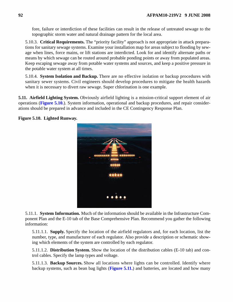
92 AFPAM10-219V2 9 JUNE 2008
fore, failure or interdiction of these facilities can result in the release of untreated sewage to thetopographic storm water and natural drainage pattern for the local area.
5.10.3. Critical Requirements. The “priority facility” approach is not appropriate in attack prepara-tions for sanitary sewage systems. Examine your installation map for areas subject to flooding by sew-age when lines, force mains, or lift stations are interdicted. Look for and identify alternate paths ormeans by which sewage can be routed around probable ponding points or away from populated areas.Keep escaping sewage away from potable water systems and sources, and keep a positive pressure inthe potable water system at all times.
5.10.4. System Isolation and Backup. There are no effective isolation or backup procedures withsanitary sewer systems. Civil engineers should develop procedures to mitigate the health hazardswhen it is necessary to divert raw sewage. Super chlorination is one example.
5.11. Airfield Lighting System. Obviously airfield lighting is a mission-critical support element of airoperations (Figure 5.10.). System information, operational and backup procedures, and repair consider-ations should be prepared in advance and included in the CE Contingency Response Plan.
Figure 5.10. Lighted Runway.
5.11.1. System Information. Much of the information should be available in the Infrastructure Com-ponent Plan and the E-10 tab of the Base Comprehensive Plan. Recommend you gather the followinginformation:
5.11.1.1. Supply. Specify the location of the airfield regulators and, for each location, list thenumber, type, and manufacturer of each regulator. Also provide a description or schematic show-ing which elements of the system are controlled by each regulator.
5.11.1.2. Distribution System. Show the location of the distribution cables (E-10 tab) and con-trol cables. Specify the lamp types and voltage.
5.11.1.3. Backup Sources. Show all locations where lights can be controlled. Identify wherebackup systems, such as bean bag lights (Figure 5.11.) and batteries, are located and how many
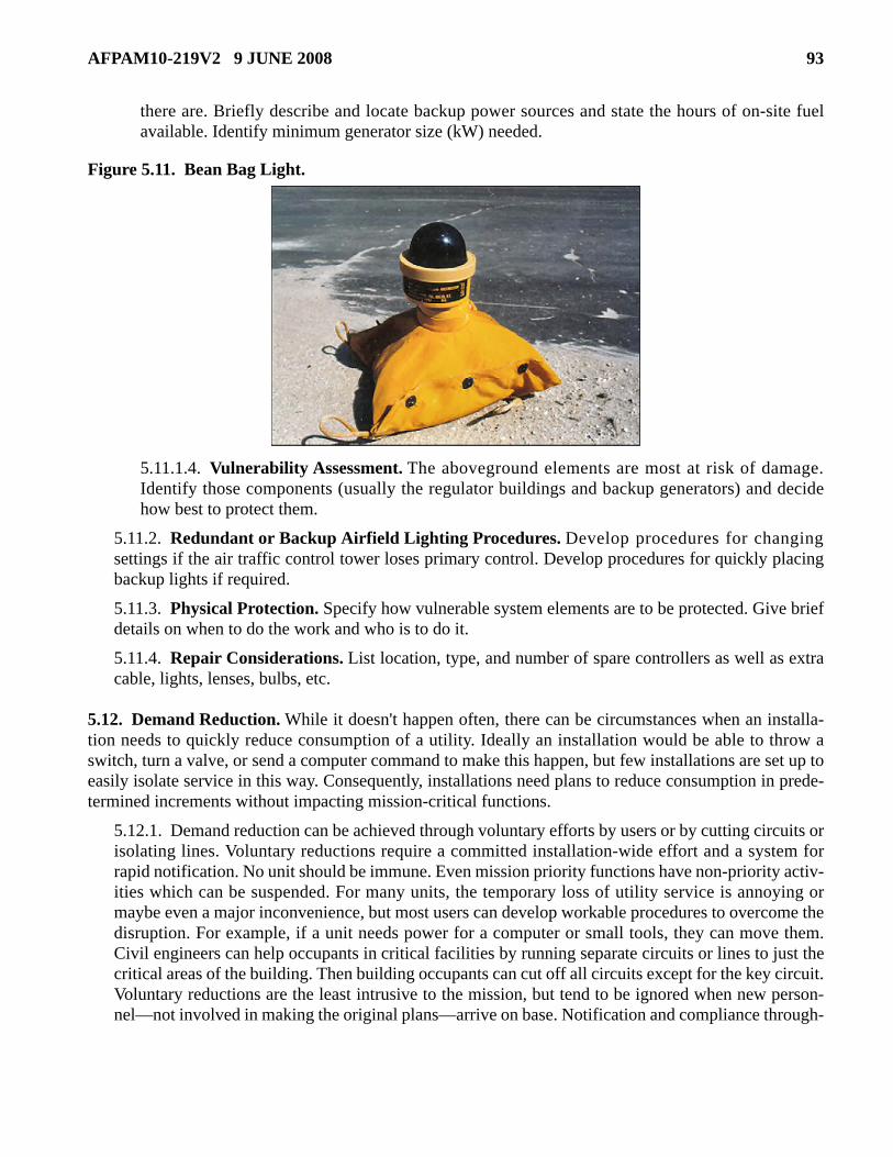
AFPAM10-219V2 9 JUNE 2008 93
there are. Briefly describe and locate backup power sources and state the hours of on-site fuelavailable. Identify minimum generator size (kW) needed.
Figure 5.11. Bean Bag Light.
5.11.1.4. Vulnerability Assessment. The aboveground elements are most at risk of damage.Identify those components (usually the regulator buildings and backup generators) and decidehow best to protect them.
5.11.2. Redundant or Backup Airfield Lighting Procedures. Develop procedures for changingsettings if the air traffic control tower loses primary control. Develop procedures for quickly placingbackup lights if required.
5.11.3. Physical Protection. Specify how vulnerable system elements are to be protected. Give briefdetails on when to do the work and who is to do it.
5.11.4. Repair Considerations. List location, type, and number of spare controllers as well as extracable, lights, lenses, bulbs, etc.
5.12. Demand Reduction. While it doesn't happen often, there can be circumstances when an installa-tion needs to quickly reduce consumption of a utility. Ideally an installation would be able to throw aswitch, turn a valve, or send a computer command to make this happen, but few installations are set up toeasily isolate service in this way. Consequently, installations need plans to reduce consumption in prede-termined increments without impacting mission-critical functions.
5.12.1. Demand reduction can be achieved through voluntary efforts by users or by cutting circuits orisolating lines. Voluntary reductions require a committed installation-wide effort and a system forrapid notification. No unit should be immune. Even mission priority functions have non-priority activ-ities which can be suspended. For many units, the temporary loss of utility service is annoying ormaybe even a major inconvenience, but most users can develop workable procedures to overcome thedisruption. For example, if a unit needs power for a computer or small tools, they can move them.Civil engineers can help occupants in critical facilities by running separate circuits or lines to just thecritical areas of the building. Then building occupants can cut off all circuits except for the key circuit.Voluntary reductions are the least intrusive to the mission, but tend to be ignored when new person-nel—not involved in making the original plans—arrive on base. Notification and compliance through-

94 AFPAM10-219V2 9 JUNE 2008
out base housing presents a special challenge. When notified of a problem, especially water,occupants tend to fill containers and tubs so they don't run out, which only worsens the problem.
5.12.2. When voluntary reductions don't work or time is critical, civil engineers can use system isola-tion to force reductions. To minimize mission impact, users need to identify key functions. Then thecircuits or distribution lines which feed those functions can be the last to be isolated. Some installa-tions have identified key circuits and rerouted lines to tie critical functions into those circuits. Unlesstime does not permit, the installation commander should approve involuntary cuts. Give as much noti-fication to units as possible. Give an after-the-fact explanation and estimated time when service willbe restored, when necessary.
5.12.3. Develop a demand reduction plan in 10 percent increments. Identify specific actions whichusers must take for each increment; for example, turning off lights, lowering the thermostat during theheating seasons and raising it during air conditioning times, minimizing flushing of toilets, curtailingequipment washing, and curtailing functions. The plan should also detail CE actions for each incre-ment: which circuits to cut, valves to turn, in what sequence, etc.
5.13. Summary. The objective of utility isolation, backup, and physical protection is to provide contin-ued utility service to mission-critical users and to minimize damage to the installation's utility systemsthrough proper advance preparations. Prepare your operating instructions and execution checklists. Doc-ument the procedures in the CE Contingency Response Plan so there is always a place to turn should theunit need information on the systems. Finally, use the checklists and practice the procedures periodicallyso each person in his or her respective utility shop can effectively respond to the unexpected. For morespecific information on utility isolation, backup, and physical protection, see reference documents listedin Table 5.3.
Table 5.3. Utility Isolation, Backup, and Physical Protection References.
Utility Isolation, Backup, and Physical Protection References AFI 10-2501, Air Force Emergency Management (EM) Program Planning and Operations. AFI 32-7062, Air Force Comprehensive Planning. AFPAM 10-219, Volume 1, Contingency and Disaster Planning. AFPAM 10-219, Volume 3, Postattack and Postdisaster Procedures. Joint Forward Operations Base (JFOB) Force Protection Handbook (to be replaced by UFC 4-027-01, Design of Deployed Operational Bases to Mitigate Terrorist Attacks).

AFPAM10-219V2 9 JUNE 2008 95
Chapter 6
BEDDOWN OPERATIONS
6.1. Introduction. A significant amount of planning and preparation must take place in order to ade-quately beddown incoming forces or disaster victims. For civil engineers, beddown usually means provid-ing facilities and utility service to military units. An Air Force forces beddown can generally be dividedinto three elements—aircraft, personnel, and infrastructure support. Aircraft support provides for mainte-nance shops, hangars, squadron operations, munitions storage, fuel storage, and other facilities thatdirectly support the flying mission. Personnel support provides for housing, feeding facilities, latrines,showers, administrative offices, and other indirect support facilities. Infrastructure support provides theutility systems, waste disposal, roads, and communications that serve the beddown site. Beddown loca-tions range from main bases with adequate existing facilities to bare bases with no facilities other thanrunways, taxiways, and aircraft parking aprons. Beddown activities are not limited to military deploy-ments. Military engineers have built extensive tent cities to house refugees and relief personnel for manydecades, and will no doubt be called on again to provide shelter for relief workers or personnel left home-less by hurricanes and other disasters (Figure 6.1.).
Figure 6.1. Beddown of FEMA Personnel in New Orleans During Hurricane Katrina.
6.2. Beddown Concepts. The unpredictable nature of Air Force deployments dictates that civil engi-neers be able to provide beddown support for differing situations. Because limited time is usually a factor,advance preparations must be made or expedient methods must be employed—in some instances, bothapproaches can be used.
6.2.1. Engineer's Role. Beddown support may be provided by in-place or deployed engineers or acombination of both. Civil engineers erect, modify, or construct many of the facilities that Air Forceunits need at deployment locations, plus engineers teach other deployed units how to erect their ownportable shelters such as TEMPER tents. Engineers also set up and operate the utility systems thatserve the aircraft and personnel support facilities. Ideally, beddowns that support OPLANs are pre-planned by the gaining major command (MAJCOM) or a subordinate unit and documented in theOPLAN, In-Garrison Expeditionary Support Plan (IGESP), or a joint support plan (JSP). Expect thelevel of detail and quality in those plans to vary. For short-notice deployments and disaster recovery

96 AFPAM10-219V2 9 JUNE 2008
support, there may be no time for advance planning. Civil engineers will be faced with making anexisting plan work or developing a new plan on the spot. Whether a plan exists or not, on-site civilengineers must provide beddown details. They must be able to develop requirements; sort out bed-down priorities to get the critical efforts started quickly—sometimes before all details are known; andthen site, lay out, and erect or modify the facilities and utility systems.
6.2.2. Advanced Echelon (ADVON) Team. Hopefully civil engineers are included in any ADVONteam sent to a non-Air Force installation to prepare for the arrival of the main deployment force.ADVON engineers should start developing beddown details, gain a sense of the commander's priori-ties, and locate vehicles and supplies. They should begin site layout and may even begin erecting shel-ters and providing limited utility support before the main force begins to arrive. Sound beddownplanning requires user input. ADVON civil engineers should solicit requirements and functional rela-tionships from other ADVON members.
6.2.3. Beddown Timing and Responsibilities. Not all beddown facilities need to be ready for occu-pancy before deploying forces start arriving. Because forces flow into an installation over a number ofdays, work can be sequenced to correspond with their arrival. The flow of forces into an installation isdetermined using a force module concept as depicted in Figure 6.2. below. This concept is furtherexplained in AFI 10-401, Air Force Operations Planning and Execution, and AFMAN 10-219, Vol-ume 6, Planning and Design of Expeditionary Airbases. Engineers usually deploy early, but are rarelyamong the first arrivals. Consequently, civil engineers are immediately in a catch-up mode of activity.As other units flow in, they should erect their own portable shelters. Of course, CE must show themwhere shelters should be erected, provide them with technical assistance, and set up utility service. Amajor CE assumption is that users erect their own shelters. This assumption is of great consequence,because there are rarely enough on-site engineers to complete all beddown tasks for the installation tobe operationally ready in the required time frame. Following intermediate beddown efforts for a mili-tary deployment, users should also be active in developing passive defense measures for their func-tions (Figure 6.3.).
6.2.4. Likely Beddown Locations. Some of the more common beddown locations include a mainUS installation, an allied main base, a bare base, and a civilian community (during disaster relief).
6.2.4.1. Main Operating Base (MOB). A MOB has extensive facilities in place for the normalbase mission. Runways, POL facilities, munitions storage areas, and permanent maintenanceshops exist which are often capable of supporting additive forces. However, depending upon localconditions and the size of the deployed force, additional feeding and housing facilities may beneeded as well as supplemental operational structures. The In-Garrison Expeditionary SupportPlan (IGESP) should specify which existing facilities incoming forces will use, what modifica-tions to those facilities will be required, and what additional facilities will have to be provided.Lacking an IGESP, an installation must quickly develop a beddown and reception plan when noti-fied of incoming military forces or civilians. The wing logistics plans office usually has the leadfor this effort, but civil engineers should have a major input on facilities. AFI 10-404 providesguidance for preparing the installation-wide plan. Sound beddown plans must always have inputson facility requirements from operations, aircraft maintenance, security forces, services, and otherfunctional areas.
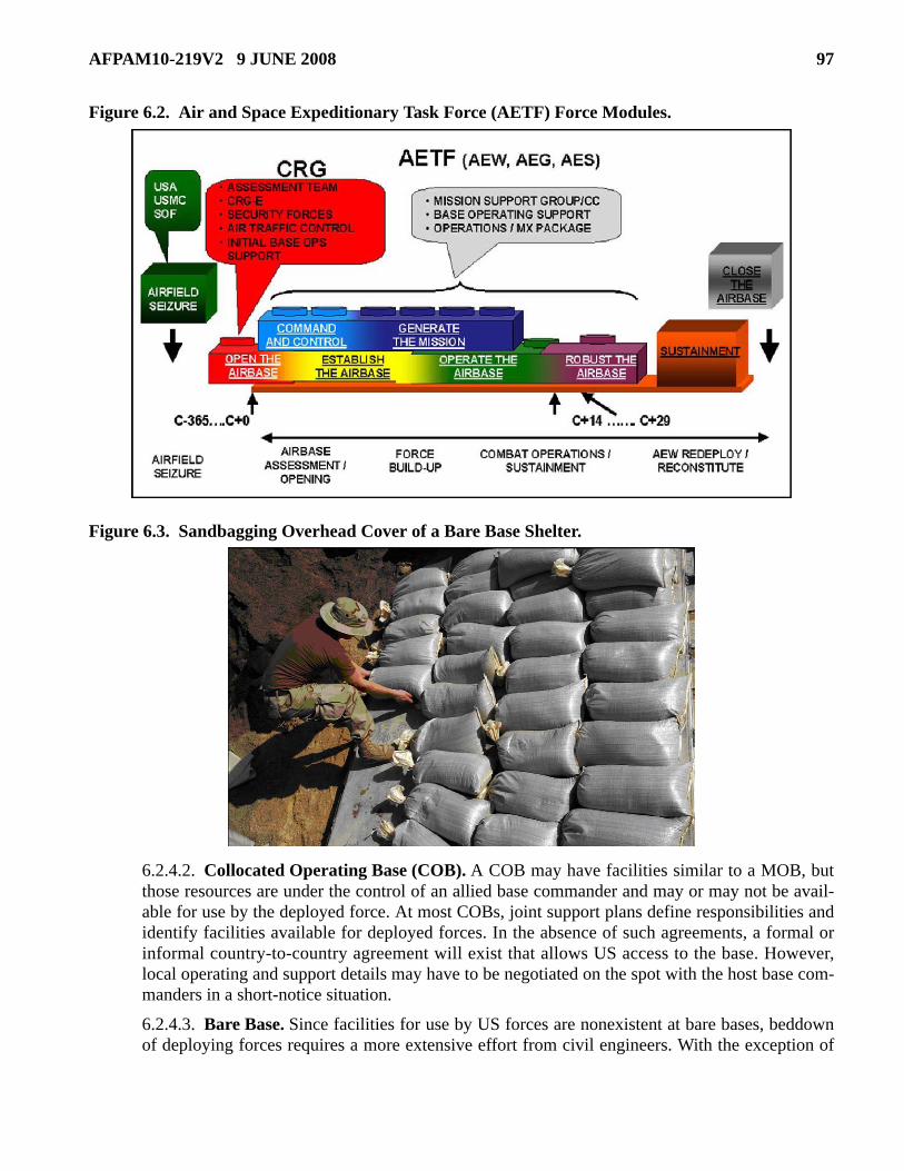
AFPAM10-219V2 9 JUNE 2008 97
Figure 6.2. Air and Space Expeditionary Task Force (AETF) Force Modules.
Figure 6.3. Sandbagging Overhead Cover of a Bare Base Shelter.
6.2.4.2. Collocated Operating Base (COB). A COB may have facilities similar to a MOB, butthose resources are under the control of an allied base commander and may or may not be avail-able for use by the deployed force. At most COBs, joint support plans define responsibilities andidentify facilities available for deployed forces. In the absence of such agreements, a formal orinformal country-to-country agreement will exist that allows US access to the base. However,local operating and support details may have to be negotiated on the spot with the host base com-manders in a short-notice situation.
6.2.4.3. Bare Base. Since facilities for use by US forces are nonexistent at bare bases, beddownof deploying forces requires a more extensive effort from civil engineers. With the exception of

98 AFPAM10-219V2 9 JUNE 2008
the runway, aircraft parking areas, and a nearby source of water, civil engineers may have to startfrom scratch to provide basic services. A tent city, or suitable substitute, must be erected to shelterdeployed forces. Basic utilities (including water, electricity, heat, sanitation) and other servicesmust be established. Aircraft parking areas may need to be expanded, revetments constructed,POL facilities developed, aircraft shelters and maintenance shops erected, and the runway modi-fied or repaired.
6.2.4.4. Civilian Communities. Less often, civil engineers may be tasked to set up tent cities incivilian communities to temporarily house disaster victims and/or deployed disaster relief forces.As with a bare base environment, permanent facilities may be nonexistent or unavailable, espe-cially following a disaster.
6.2.4.5. Other Considerations. The environment that civil engineers encounter at potentialdeployment locations can be altered at the last moment by unforeseen factors. For example, thecontingency situation at the time of deployment can drive a change in the flying mission that maydictate unexpected facility needs to accommodate the adjusted incoming forces. Enemy action ordiplomatic problems may preclude use of a planned location, making it necessary to prepareanother installation. These possibilities make it essential that civil engineers be qualified to bed-down forces in any conceivable environment.
6.2.5. CONUS Versus Theater Beddown. Force beddown will most often occur at overseas loca-tions. During war or times of international crises, combat forces quickly deploy to theater locations tosupport US and allied forces. That scenario drives the need for Air Force civil engineers to have aneffective force beddown capability. However, CONUS beddown requirements cannot be ignored.Besides disaster relief support, some CONUS installations are required to beddown large numbers ofpersonnel during periods of increased national readiness.
6.2.6. Sources of Equipment and Material Support. Quality sources of equipment and materialsupport are essential if a force beddown is to proceed without delay. Although no sources should beignored, most materials will come from WRM assets, installation resources, and local area support.
6.2.7. Manpower. Engineer manpower for force beddown operations is likely to come from PrimeBEEF teams, RED HORSE units, and local contractors. Prime BEEF teams are the cornerstone ofengineer beddown support, especially when OPLANs call for simultaneous deployments to manylocations. Although limited in number and therefore subject to availability, RED HORSE units havethe heavy construction skills and equipment needed for major beddown construction. Even in thoseinstances, Prime BEEF personnel will likely assist in the beddown and will certainly provide the con-tinuing expeditionary combat support (ECS) for the site. In many locations, it is possible to contractsupport from local construction firms to supplement Air Force engineer capabilities.
6.2.8. Construction Standards. The Joint Chiefs of Staff (JCS) established construction standardsthat outline the types of materials and construction techniques to use when constructing facilities insupport of joint operations. According to Joint Publication (JP) 3-34, Joint Engineer Operations, thesestandards minimize the engineer effort and logistics support requirements while providing facilities ofa quality consistent with mission requirements, personnel health and safety, and expected availabilityof construction resources. The standards are the same for all services where mission requirements aresimilar. The two standards used for short-term contingencies are Initial and Temporary.
6.2.8.1. Initial Standard. This standard is characterized by austere facilities with limited liferanging from 1 to 6 months (depending on the specific facility) and, in some cases, requiring

AFPAM10-219V2 9 JUNE 2008 99
replacement by more substantial or durable facilities. These facilities require minimum engineerconstruction effort. This standard is intended for immediate austere operational support of unitsupon arrival in theater. Basic Expeditionary Airfield Resources (BEAR) assets satisfy initial stan-dards. This connotation does not mean, however, that they will be replaced after 6 months but thatthey will be used by Air Forces at the onset of a conflict. It is possible that some of these mobileassets will last several years before needing replacement.
6.2.8.2. Temporary Standard. This standard is characterized by minimum facilities requiringadditional engineering effort above that required for initial standards. Temporary standard airbases provide for sustained operations above the requirements of initial standards at locationswhere a long-term presence is not anticipated. The temporary standards may be used from the startof an operation or as an upgrade from initial standards if directed by the combatant commander formission requirements. Temporary standards should increase the efficiency of operations, safety,durability, morale, and health standards for deployed personnel.
6.2.8.3. Most force beddown operations use the initial standard unless circumstances dictate oth-erwise. Table 6.1. illustrates the types of construction considered under initial and temporary stan-dards. Civil engineers tend to focus on tent and shelter erection activities of a beddown, but thistable shows that a beddown can include many other types of work.
Table 6.1. Standards of Construction.
Type of Work Initial Temporary Earthwork Minimum clearing and grading for
facility site including drainage; revetments for POL and ammo storage, A/C parking, command and control facilities.
More extensive clearing and grading to make the site easier to use during the expected period of operation.
Troop Housing/Feeding/
Administration
Tents. Wood frame structures; relocatable structures.
Electricity Generators; limited low-voltage distribution.
Generators; high and low voltage distribution.
Water Water hauled to distribution points. Limited distribution to hospitals, feeding facilities, latrines, and key users in aircraft maintenance.
Cold Storage Portable refrigerators with freezer units for medical and food services.
Refrigeration installed in prefabricated/portable structures for medical and food services. Portable refrigerators with freezers for unit use.
Sewage Organic equipment/pit or burnout latrines.
Water-borne collection to austere treatment facility. Priority: hospitals, dining halls, latrines, and high-volume users.

100 AFPAM10-219V2 9 JUNE 2008
6.3. Beddown Facilities and Utilities. Identifying existing facilities or potential cantonment areas forbeddown of incoming military forces, federal assistance teams, or disaster victims is an important disasteror attack preparation. However, CE beddown preparations do not end there; potable water sources, elec-tricity, latrines, showers, refuse collection and disposal, and contaminated waste collection and disposalare all areas that must be addressed for expedient beddown operations. This section discusses some gen-eral concepts and elements of beddown operations.
6.3.1. Beddown Facilities. There are many ways to satisfy contingency facility requirements.Always seek the solution that provides needed facilities in the least possible time. The followingoptions are listed ranging in order from most expedient to most time-consuming.
6.3.1.1. Identify Like Facilities to Share. The quickest way to provide a facility is to share orconvert a like facility that performs the same function. Sharing requires no civil engineerresources. It is accomplished by increasing the occupancy during a given time period or maintain-ing a constant occupancy while going to a multiple-shift operation. User input is essential to mak-ing this decision. Some facilities are better suited to support beddown operations than others. OnMOBs and COBs, there are aircraft hangars, maintenance shops, POL facilities, and munitionsstorage structures. If these facilities are not totally used by the host forces, parts of them can bemade available to the deployed forces. For example, a portion of aircraft maintenance shops andhangars could be devoted to the deployed force's maintenance operation. For billeting, existingtemporary quarters may accommodate small numbers of deployed personnel. Doubling or triplingthe peacetime occupancy rate of dormitories is an option.
6.3.1.2. Identify Candidate Facilities to Convert. Converting a facility is not as quick as shar-ing but is still faster than constructing a new structure. In converting a facility, the primary concernis function. Do not devote valuable time to cosmetic work to improve the appearance. Deployedpersonnel expect to live under austere conditions. Amenities can be added later when initial bed-down activities are complete. This caution applies to all beddown work. Gymnasiums, theaters,schools, or chapels are candidates for conversion. If feeding facilities are inadequate, service clubsand snack bars with existing kitchen facilities could be quickly converted to provide food toincoming troops. Several factors should be considered when selecting structures for conversion.
6.3.1.2.1. Facility Size. Certain aircraft and maintenance operations dictate the size of thefacility. For other beddown operations, such as billeting, size is not as critical. For example,one hundred personnel could be billeted in one large structure or several smaller buildings.
Airfield Pavement Expedient surfacing, such as aluminum matting.
Conventional pavement.
Fuel Storage Bladders. Bladders and steel tanks. Roads and Hardstands Stabilized with local materials. All weather with selected base
course materials. NOTE: The type of airfield surfacing to be used under temporary standards should be based on expected numbers of landings and takeoffs (cycles) by aircraft type and on the pavement loading by those aircraft.
Type of Work Initial Temporary

AFPAM10-219V2 9 JUNE 2008 101
However, the construction effort for converting numerous smaller units may be more time-consuming than for converting a single large structure.
6.3.1.2.2. Facility Location. The importance of location is a function of the proposed use ofthe structure. A building used for aircraft maintenance or aircraft operations should logicallybe in proximity to the base flightline. The location of other facilities may not be as critical, butwidely dispersed locations for related functions reduce operational efficiency of the air base.
6.3.1.2.3. Utilities Available at the Facility. Rerouting utilities could be the most time- con-suming task when converting an existing facility. Therefore, first use the structures that do notrequire extensive realignment of utility systems. For example, a gymnasium could be an excel-lent candidate for conversion to a billeting area since hot and cold running water, electricity,heat, latrines, and shower facilities are in place.
6.3.1.2.4. Construction Required. The amount of construction required to make a facilitysuitable for the beddown of forces should be a factor in its selection. Since time is a premiumduring beddown, construction should be limited to the minimum amount possible to make thefacility usable.
6.3.1.2.5. Construction Priority. The degree of importance that a facility has to the overalloperation of the air base determines its construction priority. For example, a parking area orshelter for deployed combat aircraft will have a higher construction priority than a BaseExchange facility for deployed personnel. The wing commander should set the priorities. Beprepared to give him or her recommendations.
6.3.1.2.6. Useful Life of the Converted Facility. Before civil engineers devote extensiveman-hours and materials to the conversion of a facility, determine how long it will be needed.A deployed force needing facility space for only a few weeks probably does not warrant majorremodeling of buildings or realignment of utility systems.
6.3.1.3. Identify Temporary Portable Structures if Required. When existing base facilities arenot adequate to support the beddown, planning for temporary structures will be required (such asBEAR assets, locally purchased/contracted portable facilities, or temporary facilities constructedlocally) to accommodate the overflow. Planning for temporary facilities must include the follow-ing elements:
6.3.1.3.1. Site Selection. Good site selection for the temporary facilities improves missionperformance and minimizes potential land use conflicts, such as siting structures on poorlydrained soil. Always take time to survey the installation and develop a reasonable siting plan,even if it has to be done as war threatens or after a disaster strikes. Do not take a lot of timeduring a crisis, because the plan does not have to be perfect. The degree of siting flexibilitydepends on the beddown location. At a MOB or COB, much of the land area may already bedeveloped. At a bare base or other less developed location, civil engineers usually have morelatitude. Commanders may have strong opinions on facility siting. Get those inputs early in thebeddown effort by presenting a sound siting proposal. Consider the following siting factorswhich are divided into six general categories:
6.3.1.3.1.1. Geographic Features of the Installation. Using maps and visual surveys,determine the physical features of the beddown location. Mark unsuitable areas on thedevelopmental map.

102 AFPAM10-219V2 9 JUNE 2008
6.3.1.3.1.1.1. Topography. The topography of the installation is a major siting factor.Look closely at the natural drainage patterns of the site. Attempt to site all facilities sothat cross drainage occurs, and avoid locations susceptible to ponding or flooding.Also, attempt to use natural contours when installing utility systems—let the force ofgravity help move water and sewage. This cuts down on the number of pumps needed,which decreases the loads on electrical systems. Lastly, look for areas that require theleast amount of site preparation for beddown activities.
6.3.1.3.1.1.2. Hydrological Conditions. Consider hydrological conditions such as theheight of the ground water table and its seasonal variations and the flood characteris-tics of rivers and streams bordering the site.
6.3.1.3.1.1.3. Soil Characteristics. Evaluate the soil and subgrade to determineallowable vehicle and building loads.
6.3.1.3.1.1.4. Ground Cover. Consider the amount of ground cover which must becleared and grubbed. Since time is a limiting factor under most emergency conditions,avoid sites with excessive ground cover unless facilities can be dispersed within thevegetation without excessive clearing.
6.3.1.3.1.2. Weather. The climate and weather at the beddown location may impact sitingdecisions.
6.3.1.3.1.2.1. Wind. Prevailing winds should influence the location of facilities.Locate sewage lagoons downwind of the base complex. Prevailing winds should influ-ence the orientation of buildings; when possible, do not place facility entrances so theyface the wind. This lessens the entry of dust and minimizes adverse effects on heatingand cooling systems.
6.3.1.3.1.2.2. Solar Considerations. Site facilities such that solar effects are properlyaccommodated; that is, maximized or minimized according to the time of year and lat-itudinal location. Sometimes the terrain is so featureless that you have few choices,especially in Southwest Asia (SWA).
6.3.1.3.1.2.3. Rain. The historical amount and frequency of rain or snow will indicatethe likelihood of flooding and reveal how much of a problem an installation can expe-rience with unpaved roads.
6.3.1.3.1.2.4. Tides. Consider tidal variations at coastal locations and likely stormsurges if the area is subject to hurricanes or other ocean storms during the projectedperiod of beddown.
6.3.1.3.1.3. Land Use On- and Off-Base. The activities that must take place on base and,to a lesser extent, off base are important considerations in site planning.
6.3.1.3.1.3.1. Functional Relationships. A key consideration when developing sitelayouts is the functional relationships between base activities. The base layout shouldattempt to enhance interactions between base organizations. For example, many main-tenance facilities must be on the flight line to facilitate on-aircraft maintenance; how-ever, some need not be. The avionics and parachute shops can be removed from theflight line when space is limited since direct access to the aircraft is not necessary. Sup-ply facilities need not be all in one area either. Locate some warehouses near the air-

AFPAM10-219V2 9 JUNE 2008 103
craft maintenance facilities to improve response times to the primary supplycustomers. Place the civil engineer and vehicle maintenance functions near oneanother since a large vehicle fleet is involved. Put the main dining hall near the lodgingarea to better serve the base populace. User inputs are the best way to define these rela-tionships.
6.3.1.3.1.3.2. Space for Expansion. Mission requirements change–add additionalspace in area requirements estimates to allow for expansion. Reserve land for expan-sion, particularly for functions that could require numerous facility increases, such asbilleting and supply warehousing and storage. Consider an additional buffer aroundmunitions storage areas so that increased munitions levels do not expand or shiftexplosive clear zones into areas where personnel live or work, thereby creating a viola-tion of quantity-distance criteria. Allow sufficient space around utility plants so capac-ity can be increased without significant modification. Area requirements for a facilityshould also include space for attendant facilities. For example, aircraft parking rampsshould have enough space to park the aircraft plus sufficient additional area to addrevetments. Expansion flexibility is too often overlooked in the haste to complete ini-tial siting actions. If not considered up front, it can lead to substantial problems later.Specifically, it saves the chore of relocating facilities and utilities that civil engineershave spent a lot of time erecting or constructing. If wing leadership cannot provide youwith information on installation growth, make an educated guess using the informationin this paragraph.
6.3.1.3.1.3.3. Miscellaneous Support. Another consideration, sometimes overlookedduring siting, concerns miscellaneous support facilities. They are usually small struc-tures, sometimes built by the troops themselves. For example, allow adequate spacebetween facility groups to construct protective shelters. On the flight line or in dis-persed aircraft parking areas, provide some form of sun shelters at various locations.Latrines also need to be sited near high-use areas when distant from the lodging com-plex.
6.3.1.3.1.3.4. Obstructions to Base Operations. Avoid sites with large physicalobstructions that interfere with base operations or that delay the completion of expedi-ent facilities. Check with the operations support squadron to clarify obstruction criteriafor aircraft operations.
6.3.1.3.1.3.5. Noise. Siting actions should also take noise conditions into consider-ation. Do not site lodging, dining, medical, or MWR-related facilities where their useis compromised by excessive noise. Keep these functions away from power plants,vehicle maintenance yards, and airfield pavements such as runways, taxiways, andwarm up pads. Unfortunately, it is difficult to site facilities to avoid aircraft noise at abare base. When siting is not an option to minimize noise interference, civil engineersmay resort to construction solutions such as berms or walls.
6.3.1.3.1.3.6. Access Roads and Streets. In beddown situations, transportation assetsand materials handling equipment (fork lifts, etc.) may be very limited. Place facilitiessuch as warehouses near existing roads or streets to improve access and minimize haul-ing distances where goods and materials must be moved by hand. This minimizes theneed for construction of internal roads.
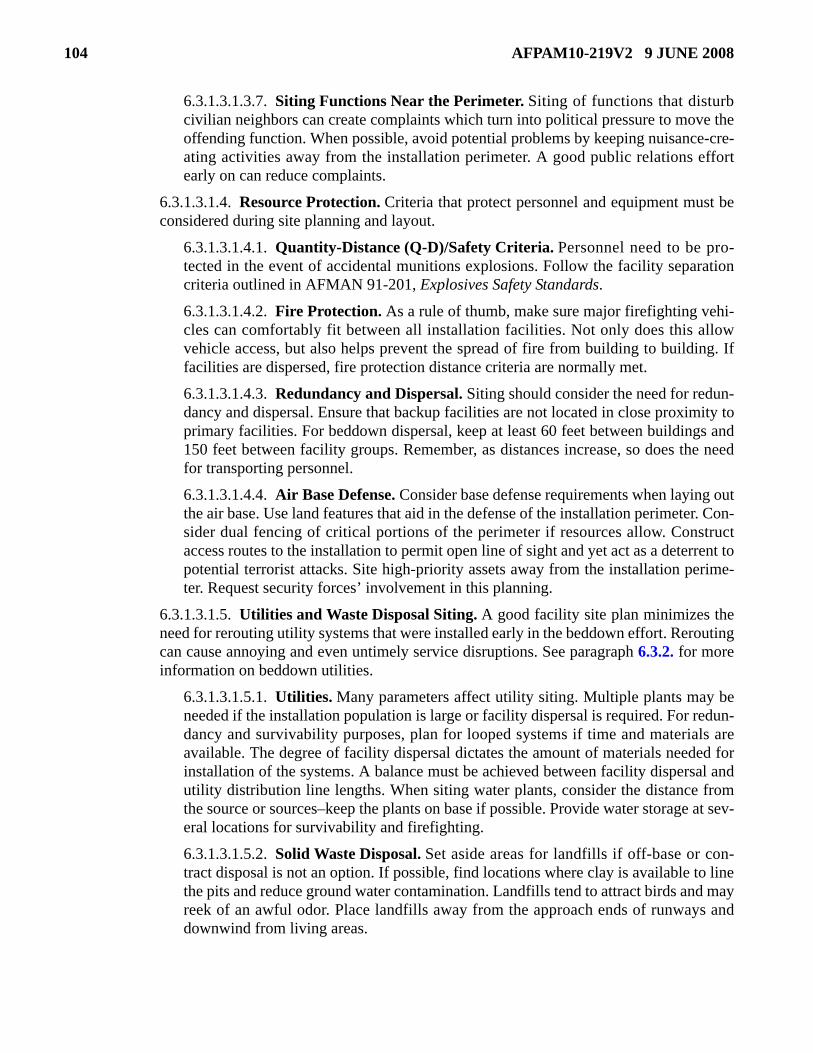
104 AFPAM10-219V2 9 JUNE 2008
6.3.1.3.1.3.7. Siting Functions Near the Perimeter. Siting of functions that disturbcivilian neighbors can create complaints which turn into political pressure to move theoffending function. When possible, avoid potential problems by keeping nuisance-cre-ating activities away from the installation perimeter. A good public relations effortearly on can reduce complaints.
6.3.1.3.1.4. Resource Protection. Criteria that protect personnel and equipment must beconsidered during site planning and layout.
6.3.1.3.1.4.1. Quantity-Distance (Q-D)/Safety Criteria. Personnel need to be pro-tected in the event of accidental munitions explosions. Follow the facility separationcriteria outlined in AFMAN 91-201, Explosives Safety Standards.
6.3.1.3.1.4.2. Fire Protection. As a rule of thumb, make sure major firefighting vehi-cles can comfortably fit between all installation facilities. Not only does this allowvehicle access, but also helps prevent the spread of fire from building to building. Iffacilities are dispersed, fire protection distance criteria are normally met.
6.3.1.3.1.4.3. Redundancy and Dispersal. Siting should consider the need for redun-dancy and dispersal. Ensure that backup facilities are not located in close proximity toprimary facilities. For beddown dispersal, keep at least 60 feet between buildings and150 feet between facility groups. Remember, as distances increase, so does the needfor transporting personnel.
6.3.1.3.1.4.4. Air Base Defense. Consider base defense requirements when laying outthe air base. Use land features that aid in the defense of the installation perimeter. Con-sider dual fencing of critical portions of the perimeter if resources allow. Constructaccess routes to the installation to permit open line of sight and yet act as a deterrent topotential terrorist attacks. Site high-priority assets away from the installation perime-ter. Request security forces’ involvement in this planning.
6.3.1.3.1.5. Utilities and Waste Disposal Siting. A good facility site plan minimizes theneed for rerouting utility systems that were installed early in the beddown effort. Reroutingcan cause annoying and even untimely service disruptions. See paragraph 6.3.2. for moreinformation on beddown utilities.
6.3.1.3.1.5.1. Utilities. Many parameters affect utility siting. Multiple plants may beneeded if the installation population is large or facility dispersal is required. For redun-dancy and survivability purposes, plan for looped systems if time and materials areavailable. The degree of facility dispersal dictates the amount of materials needed forinstallation of the systems. A balance must be achieved between facility dispersal andutility distribution line lengths. When siting water plants, consider the distance fromthe source or sources–keep the plants on base if possible. Provide water storage at sev-eral locations for survivability and firefighting.
6.3.1.3.1.5.2. Solid Waste Disposal. Set aside areas for landfills if off-base or con-tract disposal is not an option. If possible, find locations where clay is available to linethe pits and reduce ground water contamination. Landfills tend to attract birds and mayreek of an awful odor. Place landfills away from the approach ends of runways anddownwind from living areas.

AFPAM10-219V2 9 JUNE 2008 105
6.3.1.3.1.6. Available Resources and Other Logistics Factors. Some logistics issuescan influence facility siting.
6.3.1.3.1.6.1. Transportation. Availability of transportation can be an important siteselection factor. As an illustration, siting lodging for an aircraft maintenance squadronmiles from the flight line presents few problems if adequate vehicles are available totransport personnel. However, the same arrangement at an installation with limitedtransportation would cause excessive delays during shift changes.
6.3.1.3.1.6.2. Availability of Local Materials. If all other considerations are equal,select a site in proximity to local resources. This reduces transportation requirementsand base development time.
6.3.2. Beddown Utilities. Supporting utilities are essential to force beddown (Figure 6.4.). Electric-ity is needed for lighting and to power equipment. An effective sanitation system prevents the out-break of disease that can disable great numbers of the installation populace. An adequate water supplyand distribution system are required for subsistence, hygiene, and construction efforts. Dependingupon the climate, there may be a need to provide heating and air conditioning. The following para-graphs present general concepts for providing utilities during beddown operations.
6.3.2.1. Electrical Systems. For most contingency situations, some electrical support is requiredimmediately. Although the development of initial electrical service often slightly lags the erectionof facilities, it should keep pace.
6.3.2.1.1. Basic Construction Principle. Avoid constructing new systems unless absolutelynecessary. Use existing electrical production and distribution systems to the maximum extentpossible. Delay running power to any facility or function that can do without electricity. Forexample, a warehouse or storage area not used at night may have no immediate need for elec-tricity.
6.3.2.1.2. Power Source. There are two basic sources for satisfying beddown needs—exist-ing commercial power (or base-generated power) and portable generators. While the selectionusually depends on availability, a combination of these methods often offers the best solution.

106 AFPAM10-219V2 9 JUNE 2008
Figure 6.4. Engineers Lay Out Power Cables at Forward Operating Location.
6.3.2.1.3. Commercial or Base Power. If available, commercial or base power is the bestsource. One weakness of this power source is that these sources can be damaged or destroyedduring the contingency that prompted the need for force beddown. Commercial power servicecan often be restored relatively quickly following a disaster. However, the needs of the sur-rounding civilian community may be such that excess power is unavailable for use by theincoming forces. Power from an base plant depends on the damage it incurred during theemergency and its capacity to provide the additional power for the deployed forces or dis-placed victims. The configuration of the existing distribution system influences where andhow much power can be supplied in support of beddown facilities.
6.3.2.1.4. Portable Generators. The likely source of power for most beddown operations isportable generators. To aid base refueling efforts, keep the number of generators to a minimumwhen considering facility layouts and be sure to prepare a generator refueling plan. Weathercan impact generator operations. During extreme cold weather, special lubricants must beused, storage batteries must be checked frequently to prevent freezing, and moisture buildupon equipment must be removed rapidly to prevent problems. When operating in extreme heat,ensure the cooling system is cleaned and flushed at regular intervals and the coolant is main-tained at the proper level. It is also a good idea to shelter (Figure 6.5.) generators from theeffects of solar radiation in hot climates such as in Southwest Asia. Consult AFPAM 10-219,Volumes 5 and 6, and AFH 10-222, Volume 5, for more specific information on bare base elec-trical systems.

AFPAM10-219V2 9 JUNE 2008 107
Figure 6.5. Sheltered Generators.
6.3.2.2. Water System. Water is the most critical need of any beddown population. An adequatesupply of potable water must be available for human use, such as drinking, cooking, and shower-ing. Improperly treated water can spread diseases such as typhoid, dysentery, cholera, and com-mon diarrhea. Non-potable water may be used for firefighting, general decontamination, andconstruction. Water systems generally consist of four elements: source, treatment, storage, anddistribution.
6.3.2.2.1. Water Sources. The first choice for a water source should be the existing watersupply system. Often, the next best option is to haul potable water from nearby locations.Other sources include lakes, rivers, streams, ponds, wells, springs, ice, snow, distilled seawater, and rain collected in catchments. The value of any source depends on many factors:proximity to beddown location; quantity of water available versus the demand; amount oftreatment required; time and effort required to develop the source; ability to pump or transportwater from the source to the point of use, etc. If you have to use one of these alternate sourcesand everything else is equal, pick the one that appears to be the most sanitary. Water takenfrom any source, except an existing water supply system approved by the Air Force medicalteam, should be treated before use.
6.3.2.2.2. Water Treatment. The degree of water treatment depends on the level of contami-nation. Water from some ground sources may only require chlorination, while water from amuddy river requires complete treatment. If contaminated sources must be used and localtreatment is inadequate, civil engineers must set up at least the treatment and storage compo-nents of the water system contained in BEAR assets. The reverse osmosis water purificationunits (ROWPU) in those packages use a process of forcing feed water under high pressurethrough a set of membranes that screen out dissolved solids to make water potable. TheROWPU can also purify salt or brackish water. The Air Force currently uses both the600-GPH unit shown in Figure 6.6. and the 1500-GPH unit shown in Figure 6.7. Until ROW-

108 AFPAM10-219V2 9 JUNE 2008
PUs can be set up, potable water must be hauled in by truck or plane, or individuals must treattheir own water. This can be accomplished most easily by adding iodine purification tablets orcalcium hypochlorite ampules to a canteen of water. When no other method is available, watermay be rendered safe by bringing it to a boil for at least 15 seconds. Disadvantages of boilinginclude the fuel requirement, the time requirement for water to boil and then cool for con-sumption, and lack of residual protection against recontamination.
Figure 6.6. 600-GPH Reverse Osmosis Water Purification Unit (ROWPU).
Figure 6.7. 1500-GPH Reverse Osmosis Water Purification Unit (ROWPU).
6.3.2.2.3. Water Storage. If permanent water storage facilities at the beddown location arenot adequate, temporary storage facilities may be provided by using bladders from BEARassets. Civil engineers can also use tank trucks, water cans, and water bags. Non-potable waterfor firefighting and other uses may be stored in swimming pools, ornamental pools, and aban-doned basements.
6.3.2.2.4. Water Distribution. The existing water distribution system should be used whenpossible. Temporary branch lines can be run from permanent water mains using available pipeor even fire hose. Additionally, if sufficient water booster pumps are available, they may be
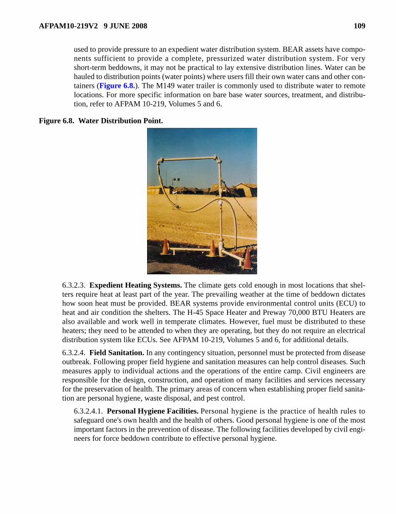
AFPAM10-219V2 9 JUNE 2008 109
used to provide pressure to an expedient water distribution system. BEAR assets have compo-nents sufficient to provide a complete, pressurized water distribution system. For veryshort-term beddowns, it may not be practical to lay extensive distribution lines. Water can behauled to distribution points (water points) where users fill their own water cans and other con-tainers (Figure 6.8.). The M149 water trailer is commonly used to distribute water to remotelocations. For more specific information on bare base water sources, treatment, and distribu-tion, refer to AFPAM 10-219, Volumes 5 and 6.
Figure 6.8. Water Distribution Point.
6.3.2.3. Expedient Heating Systems. The climate gets cold enough in most locations that shel-ters require heat at least part of the year. The prevailing weather at the time of beddown dictateshow soon heat must be provided. BEAR systems provide environmental control units (ECU) toheat and air condition the shelters. The H-45 Space Heater and Preway 70,000 BTU Heaters arealso available and work well in temperate climates. However, fuel must be distributed to theseheaters; they need to be attended to when they are operating, but they do not require an electricaldistribution system like ECUs. See AFPAM 10-219, Volumes 5 and 6, for additional details.
6.3.2.4. Field Sanitation. In any contingency situation, personnel must be protected from diseaseoutbreak. Following proper field hygiene and sanitation measures can help control diseases. Suchmeasures apply to individual actions and the operations of the entire camp. Civil engineers areresponsible for the design, construction, and operation of many facilities and services necessaryfor the preservation of health. The primary areas of concern when establishing proper field sanita-tion are personal hygiene, waste disposal, and pest control.
6.3.2.4.1. Personal Hygiene Facilities. Personal hygiene is the practice of health rules tosafeguard one's own health and the health of others. Good personal hygiene is one of the mostimportant factors in the prevention of disease. The following facilities developed by civil engi-neers for force beddown contribute to effective personal hygiene.

110 AFPAM10-219V2 9 JUNE 2008
6.3.2.4.1.1. Shower and Lavatory. Shower and lavatory areas are essential elements inproviding for effective hygiene. Personnel must have a place to maintain body cleanliness.Consider the factors in Table 6.2. when developing shower and lavatory areas.
Table 6.2. Planning Factors for Showers and Lavatories.
6.3.2.4.1.2. Laundry. A laundry helps maintain personal hygiene and contributes to theoverall comfort level by providing fresh clothing. Laundry facilities may be set up usingcommercial-type washers and dryers, or a complete field laundry may be operated by adeployed Prime RIBS (Readiness in Base Services) team. Primary civil engineer supportto either type of operation will be in the form of electrical power, an adequate water supply,and proper drainage.
6.3.2.4.2. Waste Disposal. Improper waste disposal provides breeding grounds for numerouspathogens, greatly increasing the potential for spread of disease. Therefore, an importantaspect of force beddown is the development of waste disposal systems. Of primary concern aresystems for the disposal of human waste, kitchen and bath liquid waste, garbage, and solidwaste. In some circumstances, engineers must also be concerned with toxic wastes. Whendeveloping disposal methods, bioenvironmental engineers and the units that generate thewaste should be major players. Consult AFH 10-222, Volume 4, Environmental Guide forContingency Operations Overseas, for more information on managing waste and wastewater.
6.3.2.4.2.1. Human Waste. Proper disposal of human waste is one of the most importantelements in the prevention of disease. Water supplies are easily contaminated by improperdisposal, resulting in potentially catastrophic outbreaks of disease ranging from dysentery
Planning Factors Direct drainage away from site; otherwise, water may pool around the shower area, creating a bog and growth area for bacteria and mosquitoes. Do not place the structure on grade and assume water will flow quickly away from site. Shower and lavatory facilities will receive extensive use. If set up in GP medium tents and used more than 30 days, recommend tents be hardbacked. Heat expedient shower and lavatory areas. Provide privacy screens at each entrance and exit (plywood or canvas sheet with 2” x 4” bracing). The TEMPER tent vestibules are sufficient. Provide benches for dressing and undressing. Additionally, a means of hanging clothes and towels improves the usefulness of the facility. This can be done with 1” x 6” or 1” x 4” boards, 8' to 16' long, with nails driven about 1' apart to serve as hooks. Provide individual shut-off valves at each shower head to conserve water. Lavatory area for shaving and brushing teeth should be supported by piped water. Each location should have individual water faucets. Each lavatory location should have a mirror and light. Provide an electrical outlet for every other lavatory location. In very austere conditions, large trash cans with immersion heaters can be positioned inside to provide hot water. Incorporate procedures to keep them filled and ensure temperature does not exceed 140oF.

AFPAM10-219V2 9 JUNE 2008 111
to hepatitis. Preferably deployed teams use existing sewage systems for disposal of humanwastes at MOBs or COBs. At bare bases, BEAR assets will likely be used. When the situ-ation dictates, expedient waste disposal techniques (Table 6.3.) may have to be employed.More information and specific construction techniques for these facilities are provided inAFPAM 10-219, Volumes 5 and 7.
Table 6.3. Expedient Waste Disposal Methods.
6.3.2.4.2.2. Liquid Waste. Proper disposal of liquid wastes from kitchen and bath sourcesprevents breeding grounds for harmful bacteria. On a MOB or COB, force beddown per-sonnel should attempt to connect these facilities to existing sewers. If this is not possible,kitchen liquid waste should be processed through a simply-constructed grease trap toeither a soakage pit or evaporation bed. The grease trap captures most oils and fats thatprevent, or slow down the clogging of the soil. Grease buildup happens surprisinglyquickly in grease traps. Periodically inspect and clean grease traps to ensure they continueto function properly. Details for constructing these expedient facilities are covered inAFPAM 10-219, Volumes 5 and 7.
6.3.2.4.2.3. Kitchen Garbage. Large-scale beddown operations generate tons of garbage.When allowed to accumulate without control, it provides an ideal food source for insects,rodents, and other vermin. Two primary means of garbage disposal are incineration andburial. On MOBs or COBs, large-scale garbage incinerators, sanitary landfills, or garbagecollection contracts will exist. In less developed locations, civil engineers may have todevelop improvised methods to dispose of garbage. In any case, engineers must build gar-bage collection points near food preparation facilities and arrange for periodic pickup.
6.3.2.4.2.3.1. Garbage for short-term beddown operations can be buried in small pitsor trenches. A pit 4 feet square and 4 feet deep can handle one day's garbage for 100personnel. These pits should be filled no closer than 1 foot below ground surface,sprayed with insecticide, and mounded over with compacted earth to 1 foot aboveground surface. Mark each pit with a rectangular sign on top of the mound indicatingthe type of pit and date closed. When larger pits are used, cover the garbage daily.Insecticide is not required if 2 feet of compacted soil are used for cover.
Expedient Methods for Human Waste Disposal
Portable Toilets Straddle Trench Latrines Deep Pit Latrines Burn-out Latrines Mound Latrines Bored Hole Latrines Pail Latrines Urine Soakage Pits

112 AFPAM10-219V2 9 JUNE 2008
6.3.2.4.2.3.2. For longer term operations, garbage can be buried in a continuous trenchor combined with other solid waste in a sanitary landfill. The size of the trench dependsupon the size of the force to be supported and the length of stay. Using this method, dirtexcavated while extending the trench is used to cover and mound the garbage alreadydeposited.
6.3.2.4.2.3.3. Under temporary conditions, relatively small amounts of wet garbagecan be burned in open incinerators. Expedient open incinerators may be improvisedfrom numerous materials readily available at most beddown locations. For example,55-gallon drums can be converted to make excellent barrel incinerators. When using adrum for an incinerator, ensure it is free of toxic, flammable, or combustible contents.
6.3.2.4.2.4. Solid Waste. A significant amount of solid waste is also generated at bed-down sites. Because this waste also provides an excellent breeding ground for insects androdents, it too must be disposed of properly. Dry combustible waste can be burned, butseparating the non-combustible materials is often not worth the effort. Open burning is notwithout problems. Smoke can interfere with local aircraft operations and be a nuisancedownwind. Most often, garbage and solid waste are disposed of in a common sanitarylandfill, and each day's deposit is covered with soil. Build collection points throughout theencampment and especially at locations convenient to the major waste producers. Unitsshould carry their own trash to the pickup points. Encourage units to minimize the amountof garbage they generate or at least reduce the volume they create by flattening boxes andcans. Set up a collection schedule and assign trash collection and disposal tasks to one ormore crews. See details on sanitary landfills in AFPAM 10-219, Volume 5.
6.3.2.4.2.5. Toxic Waste. To minimize ground water contamination and other publichealth problems, civil engineers may have to develop disposal options for toxic wastesgenerated on base. The best option is to eliminate the use of those products. When that isnot possible, set up procedures with installation units that generate toxic materials to min-imize their use, collect the used materials, and temporarily store them. Involve base supplyand base transportation when transporting toxic wastes. In some circumstances, the instal-lation may need to follow Environmental Protection Agency (EPA) and Department ofTransportation (DOT) rules.
6.3.2.4.2.5.1. Establish one or more hazardous waste accumulation points. Do notcommingle incompatible wastes. If possible, construct a holding area to contain anyspilled liquids. As soon as possible, work on a method to permanently and properlydispose of those wastes. Burial is an option, but double seal waste materials when pos-sible or place single-sealed containers in a lined pit. If at all possible, do not commin-gle toxic wastes with regular garbage and solid waste. Mark burial sites and identifythe name and amount of each material.
6.3.2.4.2.5.2. Construct oil-water separators to process drainage from activities suchas aircraft wash racks, aircraft fuel cell operations, engine maintenance shops, andPOL storage and transfer facilities. Be sure to set up responsibilities, procedures, and aschedule to periodically service the oil-water separators.
6.3.2.4.2.6. Medical Waste. Work with the site medical team to develop acceptable dis-posal methods for medical waste.

AFPAM10-219V2 9 JUNE 2008 113
6.3.2.4.3. Pest Control. Control of insects, rodents, and associated vermin is important dur-ing force beddown. These pests carry disease and quickly spread contamination throughout theair base if left uncontrolled. The primary means of pest control has already been discussed,that being proper disposal of waste materials and garbage. However, control of the pest popu-lation may require extermination. If that becomes necessary, consult qualified CE pest control-lers or the medical public health specialists to determine proper procedures. Insects arecontrolled by spraying an insecticide in and around nesting and feeding areas and fogging orspraying throughout the installation. Rodents are controlled with poisons or traps.
6.4. Summary. An effective force beddown capability is essential to support military operations world-wide. Beddowns are required to accommodate forces deploying to counter an actual or threatened enemyattack and to shelter victims of natural disasters and man-caused accidents. A good understanding of howto determine and satisfy beddown requirements is important. To gain a full understanding of the CE bed-down effort, explore the supporting documents listed in Table 6.4. They provide additional details on bed-down planning, scheduling, and execution and bare base equipment.
Table 6.4. Beddown References.
Other Beddown References AFPAM 10-219, Volume 5, Bare Base Conceptual Planning Guide. AFPAM 10-219, Volume 6, Planning and Design of Expeditionary Airbases. AFPAM 10-219, Volume 7, Expedient Methods. AFH 10-222, Volume 1, Guide to Bare Base Development. AFH 10-222, Volume 2, Guide to Bare Base Base Assets. AFH 10-222, Volume 4, Environmental Guide for Contingency Operations Overseas AFH 10-222, Volume 22, Refugee Camp Planning and Construction Handbook. AFI 10-404, Base Support and Expeditionary Site Planning. UFC 3-260-01, Airfield and Heliport Planning and Design.

114 AFPAM10-219V2 9 JUNE 2008
Chapter 7
ENVIRONMENTAL HAZARDS
7.1. Introduction. Planning for environmental hazards is an important step of disaster and attack plan-ning and preparations. Installations must have a plan that outlines how the base will respond to a hazard-ous material release or spill. Although the base civil engineer is responsible for the hazardous materials(HAZMAT) plan, active support by all base organizations is required. Rather than a stand-alone plan,some installations may incorporate the HAZMAT plan as an appendix in the CEMP 10-2. This chapterprovides only a brief discussion of HAZMAT planning, capability assessment, and spill response consid-erations. The primary guidance for establishing and maintaining a HAZMAT program at Air Force instal-lations is AFMAN 32-4013, Hazardous Material Emergency Planning and Response Guide, (untilrescinded by AFMAN 10-2502 Series publications). For contingency operations in foreign countries,consult AFH 10-222, Volume 4 which contains guidance on environmental considerations for Air Forcecivil engineer personnel deployed in support of overseas contingency operations.
7.2. HAZMAT Response Planning. In planning a response to a hazardous materials release or spill, ahazards analysis is an important step in the preparation process. The hazards analysis is a three-step, deci-sion-making process of collecting and analyzing information on potential HAZMAT releases. It is used toobtain a clear understanding of what hazards exist and the risk posed to personnel, property, missions, andthe environment. The information developed in a hazards analysis provides the basis for notification andreporting requirements, establishes subsequent planning priorities, and provides the documentation tosupport HAZMAT planning and response efforts. There are three key components associated with hazardsanalysis: hazard identification, vulnerability analysis, and risk analysis (Table 7.1.). Developing a com-plete hazards analysis that examines all hazards, vulnerabilities, and risks may not be practical. TheHAZMAT emergency planning team should determine the level of thoroughness needed. Resourcesshould be concentrated on those situations which present the greatest potential risk or those situationsmost likely to occur.
Table 7.1. Hazards Analysis Process.
7.2.1. Hazard Identification. Hazard Identification is the primary component in hazards analysiswhich identifies hazardous materials at specific locations or throughout the installation that are at orabove the screening levels and the release prevention measures in effect at each location.
7.2.2. Vulnerability Analysis. This is an assessment of areas potentially affected by the release of ahazardous material. It includes gathering information on the extent of the vulnerable zone, conditionsthat influence the zone, size and type of population within the zone, property that might be damaged,and the environment that might be affected.
Hazard Identification Vulnerability Analysis Risk Analysis Chemical Identity Vulnerability Zone Likelihood of a Release Occurring Location Human Populations Severity of the Consequences Quantity Critical Facilities Nature of Hazard Environment

AFPAM10-219V2 9 JUNE 2008 115
7.2.3. Risk Analysis. Risk analysis is an assessment of the likelihood of an accidental release of ahazardous material and the consequences that might result based on the estimated vulnerable zones.Risk analysis is based on the history of previous incidents at the installation, mathematical modeling,and the best available information.
7.3. HAZMAT Capability Assessment. Following the hazards analysis process, the HAZMAT emer-gency planning team conducts a thorough capability assessment to identify all installation and local com-munity resources available for response to HAZMAT releases and determines whether any additionalresources or requirements are necessary. The goal of the HAZMAT emergency planning team is to imple-ment a risk management program to ensure the resource capability is equal to the installation’s potentialHAZMAT problems. Senior leadership should determine whether or not an unprotected risk exists, and ifone does, modify that risk by either reducing their potential HAZMAT problem, increasing their responsecapability, or a combination of both. The HAZMAT emergency planning team, in conjunction with mem-bers of the emergency operations center and first/emergency responders, should conduct a capabilityassessment that accomplishes the following:
7.3.1. Identifies installation resources available for responding to a HAZMAT release.
7.3.2. Assesses personnel, funding, information sources, command and control, site management,evacuation, personal protective equipment, monitoring, release control and containment, decontami-nation, laboratory support, cleanup, and recovery.
7.3.3. Determines whether the installation needs additional resources to respond effectively.
7.3.4. Identifies available local community resources, including available commercial services, tosupplement installation shortfalls.
7.3.5. Sets up mutual aid agreements, including HAZMAT emergency response provisions, whenusing local community HAZMAT capabilities.
7.3.6. Identifies HAZMAT capability deficiencies and tracks them until it has implemented correctiveactions.
7.4. HAZMAT Spill Response Considerations. Every installation tries to prevent spills from occur-ring. However, in the unlikely event a spill does occur, effective planning and response will help mitigatethe hazard and return the affected area to productive use (Figure 7.1.). Disaster and attack preparationshelp to ensure trained personnel or contractors, equipment, and materials are available to help the basespill response team with containment, cleanup, and site restoration of hazardous substance spills.
7.4.1. Spill Response Team. Spill response teams provide containment and remediation of hazard-ous waste spills. Members vary by installation and type and size of spill response. The spill responseteam may consist of representatives from the offices listed in Table 7.2., as warranted by the magni-tude of the incident.
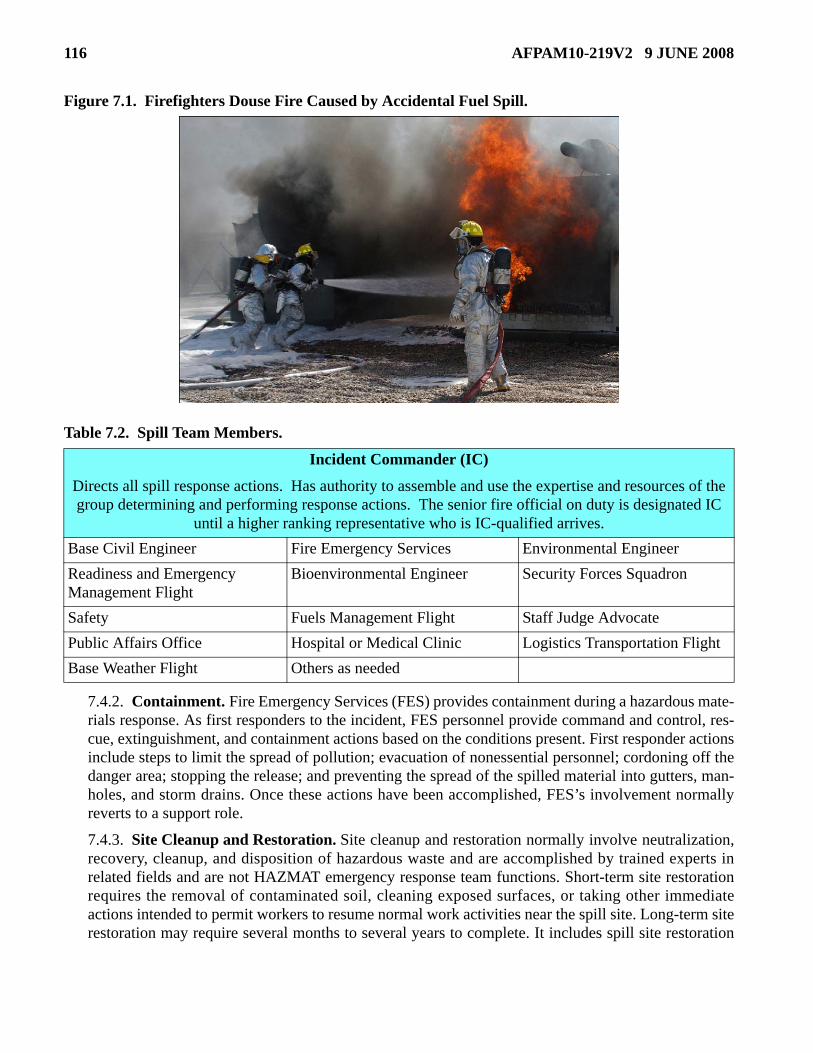
116 AFPAM10-219V2 9 JUNE 2008
Figure 7.1. Firefighters Douse Fire Caused by Accidental Fuel Spill.
Table 7.2. Spill Team Members.
7.4.2. Containment. Fire Emergency Services (FES) provides containment during a hazardous mate-rials response. As first responders to the incident, FES personnel provide command and control, res-cue, extinguishment, and containment actions based on the conditions present. First responder actionsinclude steps to limit the spread of pollution; evacuation of nonessential personnel; cordoning off thedanger area; stopping the release; and preventing the spread of the spilled material into gutters, man-holes, and storm drains. Once these actions have been accomplished, FES’s involvement normallyreverts to a support role.
7.4.3. Site Cleanup and Restoration. Site cleanup and restoration normally involve neutralization,recovery, cleanup, and disposition of hazardous waste and are accomplished by trained experts inrelated fields and are not HAZMAT emergency response team functions. Short-term site restorationrequires the removal of contaminated soil, cleaning exposed surfaces, or taking other immediateactions intended to permit workers to resume normal work activities near the spill site. Long-term siterestoration may require several months to several years to complete. It includes spill site restoration
Incident Commander (IC)
Directs all spill response actions. Has authority to assemble and use the expertise and resources of the group determining and performing response actions. The senior fire official on duty is designated IC
until a higher ranking representative who is IC-qualified arrives. Base Civil Engineer Fire Emergency Services Environmental Engineer Readiness and Emergency Management Flight
Bioenvironmental Engineer Security Forces Squadron
Safety Fuels Management Flight Staff Judge Advocate Public Affairs Office Hospital or Medical Clinic Logistics Transportation Flight Base Weather Flight Others as needed

AFPAM10-219V2 9 JUNE 2008 117
where hazardous chemicals contaminated large quantities of earth. Long-term site restoration alsoprevents further contamination, restores contaminated earth, and permits productive use of the spillsite.
7.5. Summary. War and disasters can create unexpected environmental problems. How installationsrespond can reduce the hazards, leave them unchanged, or increase them. In crises, sometimes there areno environmentally acceptable choices of action, but we must have an understanding of the choices wemake and their consequences. Do not use an emergency as an excuse to ignore environmental consider-ations. That is not smart. Poor choices can affect the installation immediately, such as allowing a toxicchemical spill to get into the installation drinking water. As a minimum, civil engineer disaster responseactions should not make an environmental problem bigger. This brief discussion should provide someinsight into HAZMAT planning and preparations. For more specific information on environmental haz-ards and response planning, see reference documents listed in Table 7.3.
Table 7.3. HAZMAT Planning and Preparation References.
HAZMAT Planning and Preparation References AFH 10-222, Volume 4, Environmental Guide for Contingency Operations Overseas. AFI 10-2501, Air Force Emergency Management (EM) Program Planning and Operations. AFPAM 10-219, Volume 1, Contingency and Disaster Planning. AFI 32-2001, The Fire Protection Operations and Fire Prevention Program. AFI 32-7006, Environmental Program in Foreign Countries. AFMAN 32-4013, Hazardous Material Emergency Planning and Response Guide. USCENTAF Spill Response Plan Template. USCENTCOM Handbook, You Spill You Dig. US Army Handbook, You Spill You Dig II.

118 AFPAM10-219V2 9 JUNE 2008
Chapter 8
SUPPORT TO AND FROM OTHERS
8.1. Introduction. Support between units is a routine activity at most air bases and is necessary to ensuredaily mission accomplishment. Likewise, the support that CE provides to and receives from others duringor after an emergency also helps to ensure mission continuity. Although the examples of support brieflydiscussed in this chapter are not all inclusive, all support provided and received by CE should be coordi-nated with the supporting/supported unit in advance and included in the Comprehensive Emergency Man-agement Plan (CEMP) 10-2. Training and exercises that periodically test and evaluate support betweenunits are also good practices. Paragraph 8.2. addresses a few agencies that may provide support to CE dur-ing emergencies, and paragraph 8.3. briefly discusses support that engineers may typically provide to oth-ers.
8.2. Support to Civil Engineers. Without the support of other agencies, civil engineers would find itextremely difficult to perform their mission during a crisis. The information in Table 8.1. is a sample ofinstallation agencies and the support they could provide to CE after an attack or disaster.
Table 8.1. Support to Civil Engineers.
Who What Support May Be Needed Vehicle Maintenance
Normal in-shop and mobile maintenance and repairs, especially for heavyequipment. Mutual support can be very beneficial—try hard to support them whenthey need help. For example, if base power is lost, set them up with a generator. Notonly will it allow them to support the installation, but it also helps to ensure yourvehicles get fixed.
Base Fuels On-site fueling of heavy construction vehicles in the field is most helpful. Fieldrefueling can save a lot of time and problems. If they cannot help, look into settingup your own refueling operation. This also applies to refueling emergencygenerators.
Supply Support Establish special supply levels for critical, but little used, items for facility /utilitysystem repairs. This helps ensure items are received quickly. A good workingrelationship with supply personnel can make the difference.
Mission Support Coordinates critical manpower support to Readiness and Emergency ManagementFlight for disaster response through Ready Augmentee Program.
Contracting and Finance
Purchase needed supplies and equipment from local sources. Negotiate and fundexpedient contract support for restoration of essential installation capabilities.Advise on best approach to acquire resources.
Aircraft Maintenance
Light carts for nighttime work, air compressors, and portable AC units. Whenrunning short of light carts, aircraft maintenance personnel usually have more ofthem than anyone else on base. They also have air compressors and portable airconditioners that may also be useful.
Services Provides box lunches or equivalent and rest and relief support for emergencyresponse crews; stocks shelters for contingencies.

AFPAM10-219V2 9 JUNE 2008 119
8.3. Civil Engineer Support to Others. Whether preparing to beddown incoming forces, respond to adisaster, or prepare for a possible attack at a forward operating base, civil engineers provide critical sup-port to base personnel and agencies. The following paragraphs provide some examples of the support CEprovides.
8.3.1. Individual Unit Assistance. As mentioned earlier, every unit has the responsibility for prepar-ing their personnel, equipment, and facilities for war, disaster, and other emergencies. One way CEassists individual units is by providing prior instruction in shelter management, CBRN defense, con-tamination control, specialized teams, and other wartime and emergency management activities. CEalso offers units on-the-spot guidance for shelter siting and erecting tents, sandbagging, and defensivefighting positions. Additionally, CE constructs berms, revetments, and ditches to support unit passivedefensive measures.
8.3.2. Mortuary Activities. The likelihood of a major attack on US air bases has diminished over theyears. However, the base mortuary officer still needs to plan for processing and burying humanremains if the number of deaths exceeds the installation’s capability to store or ship the remains homequickly. Civil engineers provide labor and equipment to assist the mortuary officer in preparing tem-porary cemeteries and mass burial sites for contaminated and non-contaminated remains. These activ-ities could involve helping the mortuary officer pre-identify burial locations and making sure theburial sites do not create an environmental problem or interfere with other uses for the proposed sites.If necessary, EOD personnel assist during the processing of remains by removing any explosive haz-ards or residue contained in the remains.
8.3.3. Casualty and Damage Reports. Casualty and damage reports are generally provided to thechain of command after an attack or disaster (Figure 8.1.). All units (primarily through their UCC andspecialized teams) report casualties, facility damage, and other situations to the EOC. However, CEmay also be called upon to assist the installation in developing unit casualty and damage reportingprocedures.
Figure 8.1. Preparations Include Procedures for Recording and Reporting Casualties.
8.3.3.1. Casualty Reports. When assisting with casualty reporting preparations, consider whatinformation needs to be reported and what unit members should do with wounded and deceased

120 AFPAM10-219V2 9 JUNE 2008
casualties if discovered. If known, address the location of casualty collection points and be awarethat these pre-selected collection points may change if affected by the attack or disaster.
8.3.3.2. Damage Reports. As the focal point for facility structure and repair, civil engineers arethe logical choice to help the installation develop damage reporting procedures. As previouslymentioned, all units should report their facility damage up the chain of command. However, do notexpect unit damage reports to be as detailed as comprehensive damage assessment reports submit-ted by CE damage assessment teams. Consider the following when assisting the installation withdamage reporting preparations: ensure procedures to gather damage assessment inputs frominstallation units are in place; set up damage assessment teams, priorities, and preset travel routes;and set up observation posts as needed.
8.3.4. Maps and Charts. Maps and charts are critical to base recovery after an attack or disaster.Although extremely important for decision makers in the ICC, EOC, DCC and other command cen-ters, maps and charts may also be instrumental to unit specialized teams and individuals performingimportant recovery tasks (Figure 8.2.). CE preparations may include preparing a master standard gridmap or maps for installation command and control; disaster response forces, damage assessmentteams, and CBRN Control Center. Airfield surface maps for minimum operating strip (MOS) selec-tion teams may also be required. Response functions need current on-base and off-base maps to per-form their missions. Regardless of who prepares them, copies of all maps should be in the primary andalternate EOC and DCC. A good preparation step is to list installation requirements for maps andcharts to support contingency operations and include instructions and an example showing how toread the installation grid map.
Figure 8.2. Command Centers, Specialized Teams, and Individuals Utilize Maps.
8.4. Summary. The support between CE and other installation agencies could be essential after an attackor disaster. The type of support discussed in this chapter highlights only a few examples of the aid andcoordination that may be necessary. These and other coordinated activities not only assist in the baserecovery, but save lives and protect property. Comprehensive base preparations, including combined

AFPAM10-219V2 9 JUNE 2008 121
training and exercises that test the unit’s ability to respond to disasters and attacks, help to ensure missioncontinuity in an emergency. Refer to the references in Table 8.2. for more information on the support thatCE provides and receives from other agencies.
Table 8.2. CE Support References.
CE Support References AFI 10-2501, Air Force Emergency Management (EM) Program Planning and Operations. AFPAM 10-219, Volume 1, Contingency and Disaster Planning. AFPAM 10-219, Volume 3, Postattack and Postdisaster Procedures.

122 AFPAM10-219V2 9 JUNE 2008
Chapter 9
BASE DENIAL
9.1. Introduction. The Department of Defense defines denial measures as actions that hinder or deny theenemy the use of space, personnel, or facilities. It may include destruction, removal, contamination, orerection of obstructions. In CE contingency response planning, base denial is an overseas theater task. Itcan become a CE task when the theater commander directs base evacuation and the destruction of selectedair base systems, military equipment, and supplies. The BCE must prepare in advance a list of candidatetargets. Denial of air base infrastructure, for the large part, will be the responsibility of the civil engineers.If available, EOD personnel will assist in carrying out some base denial operations using explosives.However, the BCE has numerous options available to effect denial operations without having to rely onthe use of demolition experts. For the main operating base (MOB) civil engineer, a denial responsibilityincludes all militarily significant civil engineer supplies and equipment, base facilities and utilities, andthe airfield pavement system. For BCEs at collocated operating bases (COBs) and bare bases, only USAForganic equipment is normally considered since real property facilities and utility systems are a hostnation responsibility. This chapter provides guidance on conventional denial procedures to be used at adeployed location. Non-explosive destruction methods are suggested for each of the basic civil engineerareas of responsibility. This chapter does not address denial operations at captured locations or speciallyidentified targets—these types of missions are normally RED HORSE tasks and will generally have a nar-rower scope of activity.
9.2. Base Denial Considerations. Because air bases have not normally been highly threatened in previ-ous conflicts, denial of an air base to enemy forces is an undertaking largely unfamiliar to the US military.However, modern warfare and the forward locations of many air bases now make the requirement for basedenial a possibility. Engineer forces will play a major role in such activities since they control significantamounts of equipment and supplies useful to an enemy and are most familiar with the utility and facilityaspects of any installation. Furthermore, the explosive demolition expertise resident within an engineersquadron makes the unit especially capable in base denial activities. Base denial actions are not haphazardevents—they require considerable preplanning and everyone’s support to be carried out effectively.
9.2.1. The theater commander will describe the policy and extent to which denial operations are car-ried out. Denial of key installations and facilities is desirable in most situations. Selected denial targetsare integrated into the overall strategic and tactical concepts of the theater operations plan and are exe-cuted in accordance with war objectives. Actual denial activities will not start until directed by theinstallation commander and only after careful consideration has been given to the possible negativeimpacts of allowing the enemy use of the air base. In addition, consideration must be given to possiblefuture use of the air base by US forces. Taking it with you when you leave (evacuation) is the pre-ferred method of denial and should be used when conditions permit. That which must be abandonedmust be denied to the enemy.
9.2.2. Targets for base denial can come in many forms and one must be selective in choosing whichtargets to address. Base denial carried to the extreme would remove or destroy everything that couldaid the enemy in any way (Figure 9.1.). Attempting to destroy an entire air base would be anextremely time-consuming task and probably beyond the capability of the normal wartime comple-ment of engineer forces at an air base. Besides matching manpower and time constraints against thescope of the overall denial task, the means selected to deny the intended target should be reasonably
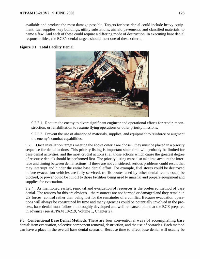
AFPAM10-219V2 9 JUNE 2008 123
available and produce the most damage possible. Targets for base denial could include heavy equip-ment, fuel supplies, key buildings, utility substations, airfield pavements, and classified materials, toname a few. And each of these could require a differing mode of destruction. In executing base denialresponsibilities, the BCE’s denial targets should meet one of these criteria:
Figure 9.1. Total Facility Denial.
9.2.2.1. Require the enemy to divert significant engineer and operational efforts for repair, recon-struction, or rehabilitation to resume flying operations or other priority missions.
9.2.2.2. Prevent the use of abandoned materials, supplies, and equipment to reinforce or augmentthe enemy’s combat capabilities.
9.2.3. Once installation targets meeting the above criteria are chosen, they must be placed in a prioritysequence for denial actions. This priority listing is important since time will probably be limited forbase denial activities, and the most crucial actions (i.e., those actions which cause the greatest degreeof resource denial) should be performed first. The priority listing must also take into account the inter-face and timing between denial actions. If these are not considered, serious problems could result thatmay interrupt and hinder the entire base denial effort. For example, fuel stores could be destroyedbefore evacuation vehicles are fully serviced, traffic routes used by other denial teams could beblocked, or power could be cut off to those facilities being used to marshal and prepare equipment andsupplies for evacuation.
9.2.4. As mentioned earlier, removal and evacuation of resources is the preferred method of basedenial. The reasons for this are obvious—the resources are not harmed or damaged and they remain inUS forces’ control rather than being lost for the remainder of a conflict. Because evacuation opera-tions will always be constrained by time and many agencies could be potentially involved in the pro-cess, base denial must follow a thoroughly developed and well rehearsed plan that the BCE preparedin advance (see AFPAM 10-219, Volume 1, Chapter 2).
9.3. Conventional Base Denial Methods. There are four conventional ways of accomplishing basedenial: item evacuation, selective component removal, destruction, and the use of obstacles. Each methodcan have a place in the overall base denial scenario. Because time to effect base denial will usually be

124 AFPAM10-219V2 9 JUNE 2008
short, attempt to use the procedure or procedures that will give the most rapid results with the leastamount of effort.
9.3.1. Evacuation. Always give serious consideration to removal of assets as a primary means ofdenial. Convoying vehicles and heavy equipment to a safer location not only denies the equipment tothe enemy, but also keeps the resource as part of our inventory (Figure 9.2.). In addition, it providestransportation for personnel and a means of relocating more critical supplies away from the air base.Obviously, because of the logistics involved (fueling, marshalling, loading, etc.), most evacuationefforts should be started early in the scheme of things and follow a preplanned schedule.
Figure 9.2. Asset Evacuation.
9.3.2. Component Removal. If evacuation of a key component is not possible, another excellentdenial option is selective component removal. This involves removing one or more components fromequipment (i.e., engines) that renders the item or equipment totally inoperative. Component removalcan be a fast and easy means of denial; however, one word of caution is in order when using this tech-nique—be sure to remove the same item(s) on all like items of equipment; otherwise, a creative oppo-nent may be able to cannibalize components from various different machines to make some operativeagain (Figure 9.3.). Lastly, do not forget to pick up any similar spares from bench stocks and supplypoints.

AFPAM10-219V2 9 JUNE 2008 125
Figure 9.3. Remove Like Components to Prevent Cannibalization.
9.3.3. Destruction. When using destruction as a means of denial, there are four primary methodsemployed: burning, soaking with water, mechanically damaging, and contaminating. One non-con-ventional method of destruction commonly included in many denial plans entails the use of explo-sives. However, due to the obvious dangers associated with handling this material, its use is normallyrestricted to specific personnel, namely explosive ordnance disposal (EOD) personnel. Although thesepersonnel are part of an installation’s civil engineer complement, they could be heavily tasked to sup-port other installation agencies and may only be able to provide limited help in the civil engineer por-tion of base denial efforts. The use of conventional, non-explosive methods of base denial will stillremain the BCE’s primary means of accomplishing the base denial mission.
9.3.3.1. Fire. Destruction by fire is a good destruction technique for a wide range of materials andequipment. Heat can often be used in a selective fashion to deform or warp items that will notburn, bringing about dysfunction. Relatively thin gauge ferrous metals are often excellent candi-dates for this procedure. Even though fire seems from outward appearances to be an ideal way ofdestroying facilities, this is not always the case. Modern building codes have brought about thedevelopment of a large variety of building materials that are highly fire resistant. Some of theseless combustible materials may need to be thoroughly saturated with fuel in order to ensure igni-tion. As a result, it is always a good approach to consult the fire department when destruction byfire is being considered. A final possible negative point to consider when selecting fire as adestruction method is that the smoke normally generated from large burning activities can serve toannounce withdrawal intentions to an enemy.
9.3.3.2. Water Soaking. Water can also be an effective means to damage many valuable assets.Unlike burning, a great advantage of using water is that it can be done quietly without revealingtelltale signs of withdrawal intentions to an enemy. It is an excellent way of destroying electricalcomponents; however, extreme caution must be used to avoid electrocution when dealing withenergized circuits. Water can also be used to contaminate a number of substances such as petro-leum fuels. In addition, many dry construction materials such as cement can be easily ruined bysimply drenching them with water (Figure 9.4.).

126 AFPAM10-219V2 9 JUNE 2008
Figure 9.4. Using Water to Ruin Bags of Cement.
9.3.3.3. Mechanical Destruction. This is another means which can be used to destroy assetswithout revealing withdrawal intentions to an enemy. Sledge hammers, axes, and wrecking barsare some of the more common tools of choice for this destruction technique.
9.3.3.3.1. More often than not, mechanical destruction is conducted in a very selective mannerrather than on a random basis. Key components of an item of equipment such as controldevices and gauges are usually where the emphasis is placed. A cutting torch can also be a use-ful tool when used judiciously. Properly trained personnel can use a torch to damage main sup-port members of metal structures such as buildings and bridges, eliminating or greatlyhindering their designed use by an enemy. Though less common, large-scale mechanicaldestruction methods can at times prove to be highly effective as well. This is particularly thecase when large quantities of equipment or materials must be destroyed or damaged expedi-ently. In such situations, heavy equipment can be used to crush items on a massive scale. Inaddition, burial can also prove to be an excellent way of denying a resource to an enemy yetstill allow its recovery by friendly forces at a future time.
9.3.3.3.2. On the average MOB, there are normally numerous systems and equipment thatrequire lubricants or coolants for proper operation. Reciprocating engines can be made dys-functional by simply draining these vital fluids and allowing the engines to run until they over-heat and seize-up. Similarly, electrical distribution transformers can be quickly ruined bydraining their cooling oil while the system is still energized. Lastly, the use of caustic sub-stances such as sulfuric and nitric acid may provide yet another useful means of destructiondenial, particularly when applied to electrical motors and electrical components (Figure 9.5.).
9.3.3.3.3. Contaminating or adulterating substances may also be used to make many industrialitems unusable. However, since no one substance is universally applicable, a technical knowl-edge of the denial target is a must. For example, sugar can wreak havoc with most reciprocat-ing engines when placed in the fuel system. And, as was mentioned earlier, water can alsocause similar results when mixed with many petroleum-based fuels.

AFPAM10-219V2 9 JUNE 2008 127
Figure 9.5. Caustic Fluid Destruction.
9.3.4. Obstacles. In addition to evacuation, component removal, and destruction, obstacles may beemployed to deny the use of certain facilities and resources to an enemy. Obstacles may be catego-rized as either natural or artificial. Due to the layout of most air bases, your primary concern will focuson the construction of artificial obstacles such as those shown in Figure 9.6. Barbed wire entangle-ments are also effective personnel obstacles (Figure 9.7.). They may not completely stop enemyground movement but can hinder and greatly slow down their forward progress when coupled with theappropriate antipersonnel devices. Check with security forces on your installation concerning theplacement and installation of antipersonnel devices; it is their responsibility to place these items. Theuse of more substantial obstacles, such as concrete and timber, can temporarily delay roadway accessor even aircraft operations when applied to airfield surfaces. Depending upon your location, there maybe numerous other natural objects that could be employed to delay or even deny an enemy’s access toyour air base—as with many other Prime BEEF functions, creative thinking can be key to the successof your effort.
Figure 9.6. Typical Obstacles.

128 AFPAM10-219V2 9 JUNE 2008
Figure 9.7. Barbed Wire Entanglement.
9.4. Base Denial Responsibilities and Techniques.
9.4.1. General Information. Ensuring that individuals know and understand the methods of basedenial is only the first step in being able to perform this type of mission. Each individual must alsoknow what his or her responsibilities might be and some of the more common techniques that can beused to physically accomplish the base denial task.
9.4.1.1. Normally, not everyone in an organization will play a role in base denial. In fact, the vastmajority of the base population will usually be directed to evacuate before consequential denialactions commence. However, if time permits, base denial activities can be expanded to include alarge percentage of the base population, but such situations would be the exception rather than thenorm. Realistically, only a very limited number of personnel, those assigned and trained as mem-bers of the base denial team, will remain behind to perform this vital role.
9.4.1.2. The actual size and composition of the denial team will be dictated by a number of factorssuch as the amount of resources identified for destruction, types of items to be destroyed, and themethods of destruction to be employed. Many base denial team assignments will be dictated byAir Force Specialties (AFS). For example, it only makes sense to have electrical personnel accom-plish base denial actions on electrical systems since they are, as a matter of course, the ones whoare intimately familiar with what type of action will best incapacitate the system. Likewise, thesame would apply to HVAC personnel, airfield surfaces and pavements and construction equip-ment personnel, fuel systems and liquid fuels systems maintenance personnel, and fire protectionpersonnel. A good rule of thumb to follow when determining denial target responsibilities is to usethe same areas of responsibility that exist under peacetime operations. In other words, if you arerequired to maintain or operate it during peacetime, also expect to be the one responsible for deny-ing it to an enemy during wartime.
9.4.2. Base Denial—Pavement/Equipment Operations.
9.4.2.1. Pavements and construction equipment personnel will be accountable for roadway, rail-way, drainage system, and airfield denial. Airfield pavements denial most often will be brought

AFPAM10-219V2 9 JUNE 2008 129
about through the use of a combination of obstacles and explosives. However, the methodemployed and the extent of damage inflicted will to a large degree be dictated by how soon andeven if we can anticipate regaining physical control of the property. If it is not unreasonable toexpect to lose control of the assets for only a short period and enemy use of the airfield during thattime will be insignificant to the total battle effort, it may be counterproductive to extensively dam-age the airfield surfaces. The final decision to seriously deny use of airfield pavements will bemade at senior command levels, and the BCE must verify the scope of pavement denial require-ments before issuing orders to commence denial operations.
9.4.2.2. Methods for performing denial of pavements, railways, drainage systems, and supportingequipment can take several forms. The following are examples of various techniques that can beapplied, singularly or in combination, to effect denial actions.
9.4.2.2.1. Use destroyed vehicles and aircraft, concrete blocks, or any kind of material that isreadily available to create obstacles on the runway.
9.4.2.2.2. Fill 55-gallon barrels with concrete and place in the aircraft landing area/runway.
9.4.2.2.3. If the airfield has an asphalt overlay, saturate selected areas with fuel to severelydamage the surface area.
9.4.2.2.4. Use heavy equipment such as bulldozers and pavement breakers to scar the surfaceof airfield pavements and damage pavements at intersections and choke points.
9.4.2.2.5. Place destroyed NAVAIDs, distance-to-go markers, and towers on the runway sur-face.
9.4.2.2.6. Block open drainage ditches with rubble, debris, and airfield damage repair (ADR)fill material to cause flooding conditions.
9.4.2.2.7. Use cement to block major drain areas and break primary drainage piping, particu-larly in those locations that would cause major airfield flooding.
9.4.2.2.8. Destroy fiberglass and metal ADR matting by driving over it with a bulldozer untilsevere deformity occurs. Place this damaged ADR matting on the airfield surfaces. Destroyany ADR component kits in the same manner.
9.4.2.2.9. Intertwine barbed tape or concertina wire around any obstacles placed on pavementsurfaces.
9.4.2.2.10. Rip up railroad spurs with heavy equipment, burn crossties, and bend rails. How-ever, be careful with timing, because rail movement could be used as a means of personnel andequipment evacuation.
9.4.2.2.11. Destroy and abandon on airfield surfaces any equipment not being evacuated bydraining the oil and running the equipment.
9.4.3. Base Denial—Electrical.
9.4.3.1. Personnel in the electrical systems AFS will be responsible for destruction of the basepower grid and its associated support complexes. This will normally include primary and second-ary distribution systems, major transformer substations, and airfield lighting systems. In addition,power production individuals will be responsible for denial activities involving prime powerplants, portable generators, and aircraft arresting systems.

130 AFPAM10-219V2 9 JUNE 2008
9.4.3.2. Methods for physically accomplishing denial of electrical systems are relatively straightforward. Use sledge hammers to destroy regulators, transformers, insulators, gauges, and shopequipment. Use chain saws to cut utility poles and barrier tapes. Vehicles and heavy equipmentcan be used to pull over towers (e.g., communications, radar, and approach control) and destroyarresting barrier facilities. Generators and arresting barrier units can be destroyed by drainingengine oil as the units are running. Lastly, key items in bench stocks, special levels, and warreserve materiel can be destroyed using some of the same methods as above.
9.4.4. Base Denial—Mechanical.
9.4.4.1. HVAC personnel will be responsible for disabling all critical base mechanical systems. Atsome theater locations, this may also include cold storage and ice plant facilities. Liquid fuels sys-tem maintenance personnel should take necessary steps to deny the use of both their system andproduct. The actual physical destruction of the pipeline itself may not be the easiest and mosteffective way of denying this crucial asset to an enemy. Instead, efforts should concentrate on con-tamination of bulk storage supplies and the destruction of key distribution system control compo-nents such as automatic valves and pumps.
9.4.4.2. Denial of mechanical systems is most easily done by physically destroying the compo-nents. Use sledge hammers to break coils, motors, condensers, pumps, gauges, heaters, coolingunits, automatic valves, and system control devices. Use cutting torches to destroy boiler units,heavy metal, and spare parts. Contaminate bulk fuel storage facilities by adding water, used oil, orsimilar substances to the fuel supplies. Due to the extreme hazard posed by some liquid fuels,draining the fuel out of the storage tanks is not recommended. However, burning of tank farmsupon evacuation from the installation is a viable denial method.
9.4.5. Base Denial—Structures and Utilities.
9.4.5.1. Structures and utility systems personnel have the primary responsibility of destroyingbuildings and the water and sewage distribution systems. Structures individuals should obtaintechnical assistance from firefighting personnel in burning facilities and any other bulk materialssuch as lumber and paint supplies. They should also use their skills with cutting torches to damagemetal support structures like bridges and aircraft shelter door rail systems. Utility systems person-nel should direct their efforts toward disabling both the potable water and sewage distribution sys-tems. Some of the key areas to concentrate on here include deep well pumps, pumping stations,storage tanks, chlorination equipment, and sewage lift stations.
9.4.5.2. Numerous methods of denying facilities and supporting utility systems are available.Some of the more useful ones include the following:
9.4.5.2.1. Collapse facilities by using vehicles and cables to remove load-bearing members.
9.4.5.2.2. Use cutting torches to cut out supporting beams to buildings such as warehouses,aircraft hangars, and maintenance areas.
9.4.5.2.3. Use sledge hammers and jack hammers to break up bricks, concrete block, and con-crete walls.
9.4.5.2.4. Place debris in major drain areas to cause facility flooding.
9.4.5.2.5. Set fire to facilities that are constructed from easily burned materials.
AFPAM10-219V2 9 JUNE 2008 131
9.4.5.2.6. Flood facilities that have below-ground utility rooms and basements or are entirelyunderground.
9.4.5.2.7. Use sledge hammers to break up pumps, motors, and main water lines within pumphouses and water plants.
9.4.5.2.8. Destroy fire hydrants using heavy construction equipment.
9.4.5.2.9. Drain and puncture water storage facilities.
9.4.5.2.10. Use cutting torches to cut supporting members of elevated water towers.
9.4.5.2.11. Pour cement and debris into main sewage lines and manholes.
9.4.5.2.12. Cut up, burn, or otherwise destroy shop stocks and construction materials.
9.4.6. Base Denial—Fire Protection. Fire protection personnel will be looked upon to provide tech-nical assistance during base denial activities primarily with respect to burning of base facilities andsupplies. They should also expect to assist in flooding of any base facilities, if necessary. Fire protec-tion vehicles should be included as part of the evacuation contingent and should be loaded with asmuch firefighting equipment as possible. Any vehicles left behind should be stripped of parts andcomponents, and any firefighting supplies that will not be taken should normally be destroyed.
9.4.7. Explosive Demolition. Except in extreme cases, traditional engineer crafts personnel will notactively conduct explosive demolition. The task falls within the scope of responsibility of explosiveordnance disposal (EOD) personnel. Some engineer forces, particularly construction equipment oper-ators, can expect to be tasked to support EOD operations if earthwork, excavation, berming, etc., needto be accomplished as part of the demolition process. Major critical facilities and airfield pavementsare the prime candidates for explosive demolition. Procedures governing explosive demolition arecontained in T.O. 11A-1-66, General Instructions, Demolitions.
9.4.8. Base Denial Safety. Regardless of specific responsibilities and techniques, effective imple-mentation of any base denial activity requires a team effort. As has already been brought out, expecttime to be very limited and the workload to be excessive. You must follow the priority listing; there isa distinct possibility that limited time or resources will not allow you to complete all desired tasks.Safety is no less important than during peacetime, even in this hectic environment. Just because hasteis a prime consideration, do not become a casualty of carelessness. Always let common sense andgood judgment prevail. Since accomplishing your mission may be a monumental undertaking, thebottom line is teamwork. Each team member must be totally capable—knowing what to do, how to doit, and when to do it.
9.5. Withdrawal and Evacuation. The final phase of base denial involves withdrawal and evacuation ofbase denial team personnel and equipment. As explained in Volume 1 of AFPAM 10-219 these activitieswere preplanned during the attack preparation phase of the contingency.
9.5.1. At the onset of base denial efforts, several key actions must be taken to ensure all personnel areaware of their responsibilities and requirements with respect to withdrawal and evacuation once phys-ical base denial missions have been completed. As a minimum, all personnel must be informed of thefollowing items:
9.5.1.1. Anticipated time available for base denial actions.
9.5.1.2. Assembly location(s) for departure convoys.

132 AFPAM10-219V2 9 JUNE 2008
9.5.1.3. Convoy method (rail, vehicle, etc.).
9.5.1.4. Personnel accountability procedures.
9.5.1.5. Preplanned withdrawal routes and end point locations.
9.5.1.6. Personal gear requirements.
9.5.2. While physical base denial actions are ongoing, another group of individuals must be desig-nated to prepare the departure convoy for movement. In all likelihood, this group will encompass per-sonnel from several base organizations; however, you can plan on having many engineer personnelinvolved as well due to the unique nature of much of the engineer equipment that will be evacuated(e.g., fire vehicles, heavy equipment, etc.). These individuals are responsible for accomplishing thefollowing tasks:
9.5.2.1. Gathering and loading supplies and materials to be evacuated on transport vehicles.
9.5.2.2. Setting up the convoy order of march.
9.5.2.3. Fueling and servicing of convoy vehicles.
9.5.2.4. Preparing route maps for convoy drivers.
9.5.2.5. Gathering and checking communications equipment.
9.5.2.6. Reconnoitering the route to be taken checking for obstacles, choke points, proper trafficsigns, etc.
9.5.2.7. Coordinating with destination point personnel to ensure support for evacuating personnel.
9.5.2.8. Arranging for en route security forces if necessary.
9.6. Summary. The execution of base denial may be forced by enemy action, or it may be a voluntary,preplanned event. In either case, base denial prevents or hinders enemy occupation and use of the airfieldcomplex, its ancillary facilities, and residual resources. The destructive work associated with the execu-tion of denial measures requires skill and resourcefulness. Employment of explosive demolition methods,a most effective means to ensure destruction of denial targets, may not be possible for a variety of reasons(shortage of EOD personnel or explosives, numerous taskings in too short a time frame, requirements toconceal our intentions, etc.). Highly effective conventional, non-explosive denial methods can be used byeach section within the base civil engineer organization. Once physical base denial actions have beenaccomplished, an orderly withdrawal and evacuation complete the base denial process.

AFPAM10-219V2 9 JUNE 2008 133
Chapter 10
INFORMATION COLLECTION, RECORDS, AND FORMS.
10.1. Information Collections. No information collections are created by this publication.
10.2. Records. The program records created as a result of the processes prescribed in this publication aremaintained in accordance with AFMAN 37-123 (will convert to AFMAN 33-363) and disposed of inaccordance with the AFRIMS RDS located at https://afrims.amc.af.mil/rds_series.cfm.
10.3. Forms (Adopted and Prescribed).
10.3.1. Adopted Forms. AF IMT 847, Recommendation for Change of Publication.
10.3.2. Prescribed Forms. No prescribed forms are implemented in this publication.
KEVIN J. SULLIVAN, Lt General, USAF DCS/Logistics, Installations and Mission Support
134 AFPAM10-219V2 9 JUNE 2008
Attachment 1
GLOSSARY OF REFERENCES AND SUPPORTING INFORMATION
References
AFDD 2-1.8, Counter-Chemical Biological, Radiological, and Nuclear Operations, 26 Jan 2007
AFDD 2-4.4, Bases, Infrastructure, and Facilities, 13 Nov 1999
AFH 10-222, Volume 1, Guide to Bare Base Development, 1 Feb 2006
AFH 10-222, Volume 2, Guide to Bare Base Assets, 1 Apr 2006
AFH 10-222, Volume 3, Guide to Civil Engineer Force Protection, 1 May 2008
AFH 10-222, Volume 4, Environmental Guide for Contingency Operations Overseas,1 Mar 2007
AFH 10-222, Volume 6, Guide to Bare Base Facility Erection, 1 Apr 1999
AFH 10-222, Volume 14, Guide to Fighting Positions, Obstacles, and Revetments, Jun 2008
AFH 10-222, Volume 22, Refugee Camp Planning and Construction Handbook, 15 Jun 2000
AFI 10-210, Prime Base Engineer Emergency Force (BEEF) Program, 24 Jul 2006
AFI 10-211, Civil Engineer Contingency Response Planning, 6 Apr 2006
AFI 10-245, Air Force Antiterrorism (AT) Standards, 21 Jun 2002
AFI 10-401, Air Force Operations Planning and Execution, 07 Dec 2006
AFI 10-404, Base Support and Expeditionary Site Planning, 9 Mar 2004
AFI 10-2501, Air Force Emergency Management (EM) Program Planning and Operations, 24 Jan 2007
AFI 32-1063, Electric Power Systems, 10 Jun 2005
AFI 32-2001, The Fire Protection Operations and Fire Prevention Program, 1 Apr 1999
AFI 32-7006, Environmental Program in Foreign Countries, 29 Apr 1994
AFI 32-7062, Air Force Comprehensive Planning, 1 Oct 1997
AFMAN 10-2602, Nuclear, Biological, Chemical, and Conventional (NBCC) Defense Operations andStandards, 23 May 2003
AFMAN 32-4005, Personnel Protection and Attack Actions, 30 Oct 2001
AFMAN 32-4013, Hazardous Material Emergency Planning and Response Guide, 1 Aug 1997
AFMAN 33-363, Management of Records, 1 Mar 2008
AFMAN 91-201, Explosive Safety Standards, 18 Oct 2001
AFPAM 10-219, Volume 1, Contingency and Disaster Planning, June 2008
AFPAM 10-219, Volume 3, Civil Engineer Disaster and Attack Recovery Procedures, Jun 2008
AFPAM 10-219, Volume 5, Bare Base Conceptual Planning Guide, 1 Jun 1996
AFPAM 10-219, Volume 6, Planning and Design of Expeditionary Airbases, 1 Feb 2006

AFPAM10-219V2 9 JUNE 2008 135
AFPAM 10-219, Volume 7, Expedient Methods, Jun 2008
AFPAM 10-219, Volume 8, Prime Base Engineer Emergency Force (BEEF) Management,
30 Aug 2007
AFPAM 32-1004, Volume 5, Working in the Operations Flight Infrastructure Support, 1 Sep 1998
AFPD, 10-24, Air Force Critical Infrastructure Program (CIP), 28 Apr 2006
AFRIMS RDS, https://afrims.amc.af.mil/rds_series.cfm
AFTTP (I) 3-2.46, Multiservice Tactics, Techniques, and Procedures for Nuclear, Biological, and Chemi-cal (NBC) Protection, 1 June 2003
AFVA 10-2510, U.S. Air Force Emergency Notification Signals, 1 Nov 2003
AFVA 10-2511, USAF Standardized Attack Warning Signals for Medium and High Threat
Areas, 24 Dec 2002
JP 3-34, Joint Engineer Operations, 12 Feb 2007
Joint Forward Operations Base (JFOB) Force Protection Handbook, 1 May 2008 ( to be replaced byUFC 4-027-01, Design of Deployed Operational Bases to Mitigate Terrorist Attacks)
T.O. 11A-1-66, General Instructions, Demolitions, 1 Aug 2003
T.O. 35E2-4-1, Repair Quality Criteria System for Rapid Runway Repair, 31 May 1990
UFC 3-230.03A, Water Supply, 16 January 2004
UFC 3-230-09A, Water Supply: Water Storage, 16 January 2004
UFC 3-260-01, Airfield and Heliport Planning and Design, 1 Nov 2001
UFC 3-340-01, Design and Analysis of Hardened Structures to Conventional Weapons Effects, 30 Jun2002
UFC 4-010-01, DOD Minimum Antiterrorism Standards for Buildings, 8 Oct 2003
UFC 4-021-01, Design and O&M: Mass Notification Systems, 18 Dec 2002
UFC 4-022-01, Entry Control Facilities/Access Control Points, 25 May 2005
USCENTAF Spill Response Plan Template
USCENTCOM Handbook, You Spill You Dig
USAF Civil Engineer Supplement to War and Mobilization Plan (WMP-1)
US Army Handbook, You Spill You Dig II
Abbreviations and Acronyms
ABD—Air Base Defense
ADR—Airfield Damage Repair
ADVON—Advanced Echelon
AETF—Air and Space Expeditionary Task Force
136 AFPAM10-219V2 9 JUNE 2008
AF—Air Force
AFCESA—Air Force Civil Engineer Support Agency
AFDD—Air Force Doctrine Document
AFH—Air Force Handbook
AFI—Air Force Instruction
AFIMS—Air Force Incident Management System
AFMAN—Air Force Manual
AFPAM—Air Force Pamphlet
AFRIMS—Air Force Information Management System
AFS—Air Force Specialty
AFTTP—Air Fore Tactics, Techniques, and Procedures
AFVA—Air Force Visual Aid
AGE—Aerospace Ground Equipment
AIR—American Institute for Research
ANG—Air National Guard
AT—Antiterrorism
ATO—Antiterrorism Officer
BCE—Base Civil Engineer
BDOC—Base Defense Operations Center
BEAR—Basic Expeditionary Airfield Resources
BHP—Boiler Horsepower
BSP—Base Support Plan
BTU—British Thermal Unit
C2—Command and Control
CBRN—Chemical, Biological, Radiological, and Nuclear
CBRNE—Chemical, Biological, Radiological, Nuclear, and High-Yield Explosives
C-CBRN—Counter- Chemical, Biological, Radiological, and Nuclear
CEMP—Comprehensive Emergency Management Plan
CCA—Contamination Control Area
CE—Civil Engineer
CO2—Carbon Dioxide
COB—Collocated Operating Base

AFPAM10-219V2 9 JUNE 2008 137
COMSEC—Communications Security
CONEX—Container Express
CONUS—Continental United States
COTS—Commercial Off-the-Shelf
CRP—Contingency Response Plan
DART—Damage Assessment Response Team
DCC—Damage Control Center
DEFCON—Defense Readiness Conditions
DOD—Department of Defense
DOT—Department of Transportation
EAID—Equipment Authorization Inventory Data
EAP—Emergency Actions Procedures
ECC—Emergency Communications Center
ECS—Expeditionary Combat Support
ECU—Environmental Control Unit
EM—Emergency Management
EMCS—Energy Monitoring and Control Systems
EOC—Emergency Operations Center
EOD—Explosive Ordnance Disposal
EPA—Environmental Protection Agency
ESF—Emergency Support Function
ESP—Expeditionary Site Plans
ET—Effective Temperature
FAX—Facsimile
FACC—Fire Alarm Communications Center
FES—Fire Emergency Services
FEMA—Federal Emergency Management Agency
FPCON—Force Protection Condition
FPWG—Force Protection Working Group
GPM—Gallons per Minute
GPH—Gallons per Hour
HAZMAT—Hazardous Material
138 AFPAM10-219V2 9 JUNE 2008
HE—Harvest Eagle
HF—Harvest Falcon
HTHW—High Temperature Hot Water
HVAC—Heating, Ventilation, and Air Conditioning
IC—Incident Commander
ICC—Installation Control Center
IGESP—In-Garrison Expeditionary Site Plans
INWS—Installation Notification and Warning System
IMT—Information Management Tool
IPE—Individual Protective Equipment
JCS—Joint Chiefs of Staff
JFOB—Joint Forward Operations Base
JP—Joint Publication
JSP—Joint Support Plan
kW—Kilowatt
LIMFAC—Limiting Factor
LNG—Liquified Natural Gas
LPG—Liquified Petroleum Gas
MAJCOM—Major Command
MBTU—One Million British Thermal Units
MEOC—Mobile Emergency Operations Center
MNS—Mass Notification System
MOB—Main Operating Base
MOPP—Mission-Oriented Protective Posture
MOS—Minimum Operating Strip
MRE—Meal, Ready-To-Eat
NATO—North Atlantic Treaty Organization
NAVAIDS—Navigational Aids
NBC—Nuclear, Biological, and Chemical
NEO—Non-Combatant Evacuation Operations
NPDES—National Pollutant Discharge Elimination System
NRDL—Naval Radiological Defense Laboratory

AFPAM10-219V2 9 JUNE 2008 139
NUDET—Nuclear Detonation
OI—Operating Instruction
OPLAN—Operation Plan
OPR—Office of Primary Responsibility
OSHA—Occupational Safety and Health Administration
POL—Petroleum, Oils, and Lubricants
Prime BEEF—Prime Base Engineer Emergency Force
Prime RIBS—Prime Readiness in Base Services
PSI—Pounds per Square Inch
PSIG—Pounds per Square Inch Gauge
RDS—Records Disposition Schedule
RED HORSE—Rapid Engineer Deployable Heavy Operational Repair Squadron, Engineer
ROWPU—Reverse Osmosis Water Purification Unit
RPIE—Real Property Installed Equipment
RPM—Rotations per Minute
SCPS—Survivable Collective Protection Systems
SF—Security Forces
SRR—Survival, Recovery, and Reconstitution
STANAG—Standardization Agreement (used in NATO)
SWA—Southwest Asia
TEMPER—Tent, Extendable Modular Personnel
TOL—Take-Off and Landing
UAV—Unmanned Aerial Vehicle
UCC—Unit Control Center
UFC—Unified Facilities Criteria
UPS—Uninterruptible Power System
US—United States
USAF—United States Air Force
USAFE—United States Air Forces in Europe
UXO—Unexploded Explosive Ordnance
WRM—War Reserve Materiel

140 AFPAM10-219V2 9 JUNE 2008
Terms
Air Base Defense—Those measures taken to nullify or reduce the effectiveness of enemy attacks on, orsabotage of, air bases to ensure that the senior commander retains the capability to accomplish assignedmissions.
Airfield Damage Repair (ADR)—The process of using construction equipment, tools, portableequipment, expendable supplies, and temporary surfacing materials to provide a minimum operatingsurface through expedient repair methods.
Air Force Civil Engineer Support Agency (AFCESA)—A field operating agency (FOA) located atTyndall Air Force Base, Florida. The Directorate of Contingency Support (HQ AFCESA/CEX) acts as theAir Force program manager for Base Civil Engineer (BCE) Contingency Response Planning.
Alert Condition—A level of readiness which military forces are to achieve, usually based on a definedlevel of threat. Predetermined preparation instructions are implemented upon declaration of each alertcondition. Examples of alert conditions include defense conditions (DEFCON) and hurricane conditions(HURCON). Within each condition, there are usually five levels of readiness.
B-1 Revetment—A galvanized metal revetment assembled using metal pins and filled with sand orsimilar material. B-1 revetments are often capped with concrete to prevent water from entering the fillmaterial. They are primarily used to protect parked aircraft, however, they can also be used for facilityhardening.
Bare Base—An installation having minimum essential facilities to house, sustain, and support operationsto include, if required, a stabilized runway, taxiways, and aircraft parking areas. A bare base must have asource of water that can be made potable. Other requirements to operate under bare base conditions forma necessary part of the force package deployed to the bare base.
Base Denial—The destruction or denial of vital air base resources so the enemy cannot use them againstfriendly forces or for his benefit.
Basic Expeditionary Airfield Resources (BEAR)—Facilities, equipment, and basic infrastructure tosupport the beddown of deployed forces and aircraft at austere locations; a critical capability to fieldingexpeditionary aerospace forces. Also known as BEAR, the resources include tents, field kitchens, latrinesystems, shop equipment, electrical and power systems, runway systems, aircraft shelters, and waterdistribution systems needed to sustain operations.
Beddown—The act of providing facilities, utilities, services, construction, operations and maintenancesupport to a deployed force with the overall intent of establishing a basic mission capability.
Bitburg Revetment—A fork lift-moveable revetment made of reinforced concrete usually used forfacility hardening.
CBRN Control Center—A sub-element of the Emergency Operations Center that directs CBRNreconnaissance activities to shape the hazards and advises the commander on hazards, countermeasures,and protective actions.
Civil Engineer Control Center—The primary center for controlling CE forces responding to a crisis,emergency, or other contingency. Synonymous with Damage Control Center.

AFPAM10-219V2 9 JUNE 2008 141
Chemical, Biological, Radiological and Nuclear (CBRN) Defense—The methods, plans, proceduresand training required to establish defense measures against the effects of attack by nuclear weapons orchemical and biological agents.
Chemical Warfare—All aspects of military operations involving the employment of lethal andincapacitating munitions/agents and the warning and protective measures associated with such offensiveoperations. Since riot control agents and herbicides are not considered to be chemical warfare agents,those two items will be referred to separately or under the broader term “chemical,” which will be used toinclude all types of chemical munitions/agents collectively. The term “chemical warfare weapons” maybe used when it is desired to reflect both lethal and incapacitating munitions/agents of either chemical orbiological origin.
Collocated Operating Base (COB)—An active or Reserve allied airfield designated for joint orunilateral use by US Air Force wartime augmentation forces or for wartime relocation of US Air Forcein-theater forces. COBs are not US installations.
Command and Control—The exercise of authority and direction by a properly designated commanderover assigned and attached forces in the accomplishment of the mission. Command and control functionsare performed through an arrangement of personnel, equipment, communications, facilities, andprocedures employed by a commander in planning, directing, coordinating, and controlling forces andoperations in the accomplishment of the mission.
Communications Security (COMSEC)—The protection resulting from all measures designed to denyunauthorized persons information of value which might be derived from the possession and study oftelecommunications, or to mislead unauthorized persons in their interpretation of the results of suchpossession and study. Communications security includes: cryptosecurity, transmission security, emissionsecurity, and physical security of communications security materials and information.
Continental United States (CONUS)—United States territory, including the adjacent territorial waters,located within North America between Canada and Mexico.
Contingency—An emergency involving military forces caused by natural disasters, terrorists,subversives, or by required military operations. Due to the uncertainty of the situation, contingenciesrequire plans, rapid response, and special procedures to ensure the safety and readiness of personnel,installations, and equipment.
Contingency Response Plan—A base civil engineer plan of action developed in anticipation of all typesof contingencies, emergencies, and disasters.
Contingency Support Staff—See emergency operations center.
Conventional Weapon—A weapon which is neither nuclear, biological, nor chemical.
Counterterrorism—Offensive measures taken to prevent, deter, and respond to terrorism.
Damage Control Center—A command and control node for engineer forces at unit level which controlsCE preparations and recovery activities for disasters and attacks.
Decontamination—The process of making any person, object, or area safe by absorbing, destroying,neutralizing, making harmless, or removing chemical or biological agents or by removing radioactivematerial clinging to or around it.

142 AFPAM10-219V2 9 JUNE 2008
Defensive Fighting Positions—Fortifications constructed at various locations around an installation toassist in air base defense operations. These positions can vary from hastily built bunkers to elevated,hardened towers. Usually constructed to support security forces requirements, fighting positions can alsobe built for work party security purposes or specific point defense needs.
Dispersal—Relocation of forces for the purpose of increasing survivability.
Emergency Communications Center (ECC)—A central dispatch capability that includes the minimumfunctions of the Fire Alarm Communications Center (FACC), Security Forces Desk, and Medical dispatch(when applicable).
Emergency Operations Center (EOC)—For the purposes of AFIMS, the EOC is the C2 supportelement that directs, monitors, and supports the installation’s actions before, during, and after an incident.The EOC is activated and recalled as necessary by the Installation Commander. The EOC updates the ICCwith ongoing incident status and seeks support through the ICC when on-scene requirements surpass theinstallation’s inherent capability and the installation’s cumulative capabilities acquired through mutual aidagreements. According to the National Response Plan (NRP), the EOC is defined as “The physicallocation at which the coordination of information and resources to support attack response and incidentmanagement activities normally takes place. An EOC may be a temporary facility or may be located in amore central or permanently established facility, perhaps at a higher level of organization within ajurisdiction. EOCs may be organized by major functional disciplines such as fire, law enforcement, andmedical services; by jurisdiction such as Federal, State, regional, county, city, or tribal; or by somecombination thereof.”
Emergency Support Function (ESF)—ESFs are groupings of capabilities into an organizationalstructure that provides the support, resources, program implementation, and services that are most likelyto be needed during an incident. ESFs also serve as the primary operational-level mechanism thatprovides support during an incident.
Evacuation—1. Removal of a patient by any of a variety of transport means (air, ground, rail, or sea)from a theater of military operation or between health service support capabilities for the purpose ofpreventing further illness or injury, providing additional care, or providing disposition of patients from themilitary health care system. 2. The clearance of personnel, animals, or materiel from a given locality. 3.The controlled process of collecting, classifying, and shipping unserviceable or abandoned materiel, USor foreign, to appropriate reclamation, maintenance, technical intelligence, or disposal facilities. 4. Theordered or authorized departure of non-combatants from a specific area by Department of State,Department of Defense, or appropriate military commander. This refers to the movement from one area toanother in the same or different countries. The evacuation is caused by unusual or emergencycircumstances and applies equally to command or non-command-sponsored family members.
Expeditionary Site Plan (ESP)—ESPs are chiefly associated with locations without a permanent AirForce presence and may contain only the minimum data necessary to make initial beddown decisions.ESPs may be developed in short time frames to meet contingency needs without full staffing orcoordination. It is the installation-level or site plan to support unified and specified command wartimeoperations plans as well as MAJCOM supporting plans. It cuts across all functional support areas in aconsolidated view of installation missions, requirements, capabilities, and limitations to plan for actionsand resources supporting war or contingency operations, including deployment, post-deployment, andemployment activities (as appropriate).

AFPAM10-219V2 9 JUNE 2008 143
Explosive Ordnance Disposal (EOD)—The detection, identification, on-site evaluation, rendering-safe,recovery and final disposal of unexploded explosive ordnance. It may also include explosive ordnancewhich has become hazardous by damage or deterioration.
Facility—A real property entity consisting of one or more of the following: a building, a structure, autility system, pavement, and underlying land. (FEMA uses the term differently. It can be a base, aninstallation, an industrial plant, one building or a collection of buildings which together are used toprovide a product or service.)
Force Beddown—The provision of expedient facilities for troop support to provide a platform for theprojection of force. These facilities may include modular or kit-type substitutes.
General Purpose (GP) Vehicles—Vehicles which have no special capabilities and can be used by anyunit. Such vehicles include pickup trucks, sedans, 1 1/2-ton trucks, vans, etc.
Giant Voice System—An installation-wide public address system used to broadcast changes in alertstatus and provide personnel warning.
Hardening—The process of providing protection against the effects of conventional weapons. It can alsoapply to protection against the side effects of a nuclear attack or against the effects of a chemical orbiological attack.
Harvest Eagle—A nickname for an air transportable package of housekeeping equipment, spare parts,and supplies required for support of US Air Force general-purpose forces and personnel in bare baseconditions. Examples of Harvest Eagle equipment are water purification units, tents, and showers. Eachkit is designed to provide softwall housekeeping support for 1,100 personnel. (Replaced by BasicExpeditionary Airfield Resources.)
Harvest Falcon—Harvest Falcon is a nickname given to a selected package of mobile facility, utility, andequipment assets required to support forces and aircraft under bare base conditions. These WRM assetsare packaged in air transportable sets to include housekeeping, industrial, initial flight line and follow-onflight line. Harvest Falcon sets are designed to support increments of 1,100 personnel and squadron sizeaircraft deployments. (Replaced by Basic Expeditionary Airfield Resources.)
Hazardous Material (HAZMAT)—Materials which harm personnel or their environment when notproperly handled.
High Threat Area—An area which, because of its location or strategic targets, is highly susceptible toenemy attacks.
Host Nation—A nation which receives the forces and/or supplies of allied nations and/or NATOorganizations and permits such forces and supplies to be located on, to operate in, or to transit through itsterritory.
Incident Commander (IC)—The command function is directed by the IC, who is the person in charge atthe incident and who must be fully qualified to manage the response. Major responsibilities for the ICinclude: performing command activities, such as establishing command; protecting life and property;controlling personnel and equipment resources; maintaining accountability for responder and publicsafety and for task accomplishment; and establishing and maintaining an effective liaison with outsideagencies and organizations, including the EOC when it is activated.
In-Garrison Expeditionary Site Plan (IGESP)—Primarily developed for locations with a permanentAir Force presence, and are fully developed by the collaborative planning efforts of many functional

144 AFPAM10-219V2 9 JUNE 2008
experts with a deliberate planning time line. Replaces the former term Base Support Plan (BSP). All plansformerly called BSPs will be redesignated IGESPs. The term IGESP describes all plans developed tomeet deliberate planning requirements, contingency planning requirements, and any other site planningrequirements. While the term BSP is superseded; the requirement for robust, structured, and standardizedsite planning based on AFI 10-404 remain.
Installation Control Center (ICC)—The ICC directs actions supporting the installation's mission. Asthe focal point for installation-wide notification and operation, the ICC receives and sends orders,information, and requests pertinent to the assigned task.
Joint Support Plan (JSP)—A plan for the reception and beddown of forces which is collectivelydeveloped by the host nation, the theater in-place sponsor, and the affected augmentation unit. The planoutlines all facets of operations at a collocated operating base to include personnel, facilities, andequipment.
Level of Threat—The relative likelihood that a specific threat will occur and have an impact on a base oron friendly forces in a theater of operation. As the level of a threat increases, military forces prepare for it,usually based on actions predetermined for each defined level of threat.
Limiting Factor (LIMFAC)—A factor or condition that, either temporarily or permanently, impedesmission accomplishment. Illustrative examples are transportation network deficiencies, lack of in-placefacilities, malpositioned forces or materiel, extreme climatic conditions, distance, transit or overflightrights, political conditions, etc.
Main Operating Base (MOB)—A base on which all essential buildings and facilities are erected. Totalorganizational and intermediate maintenance capability exists for assigned weapon systems. Theintermediate maintenance capability may be expanded to support specific weapon systems deployed tothe MOB.
Minimum Operating Strip (MOS)—As used in this volume, the launch and recovery pavement surface,selected for repair after an attack, which meets the minimum requirements for operating assigned ortransient aircraft at maximum or combat gross weight.
Mobile Emergency Operations Center (MEOC)—The MEOC is an emergency response vehicleassigned to the CE Readiness Flight. It provides the IC with command, control, and communicationssupport for emergency response and recovery operations.
Operations Management Center (OMC)—As one of four elements of the installation control center,provides 24-hour manning of the Emergency Action Cell to handle communications to and from higherheadquarters, emergency actions, and flight following.
Operations Security (OPSEC)—A process of identifying critical information and subsequentlyanalyzing friendly actions attendant to operations and other activities to: (a) identify those actions that canbe observed by adversary intelligence systems, (b) determine indicators hostile intelligence systems mightobtain that could be interpreted or pieced together to derive critical information in time to be useful toadversaries, and (c) select and execute measures that eliminate or reduce to an acceptable level thevulnerabilities of friendly actions to adversary exploitation.
Passive Defense—As used in this volume, measures taken on or around an installation to reduce theprobability of and to minimize the effects of damage caused by hostile action.

AFPAM10-219V2 9 JUNE 2008 145
Petroleum, Oils, and Lubricants (POL)—POL is a generic term for class III supplies. In Air Force use,it often is used to refer to jet fuels.
Planning Factor—A multiplier used in planning to estimate the amount and type of effort involved in acontemplated operation. Planning factors are often expressed as rates, ratios, or lengths of time. From anengineering perspective, planning factors are often expressed as lump sums or on a per aircraft or perperson basis.
Potable Water—Water which is safe for consumption.
Prime BEEF (Base Engineer Emergency Forces)—Worldwide civil engineer forces organized toprovide trained military elements used in direct combat support or emergency recovery from naturaldisasters.
Readiness—The ability of US military forces to fight and meet the demands of the national militarystrategy. Readiness is the synthesis of two distinct but interrelated levels: (a) Unit Readiness—The abilityto provide capabilities required by the combatant commanders to execute their assigned missions. This isderived from the ability of each unit to deliver the outputs for which it was designed. (This includes theability to deploy and employ without unacceptable delays.) and (b) Joint Readiness—The combatantcommander’s ability to integrate and synchronize ready combat and support forces to execute his/herassigned missions. (Readiness is one of four components of military capability. The other three are forcestructure, modernization, and sustainability.)
RED HORSE—Organizations established to provide the Air Force with a highly mobile, self-sufficient,rapidly deployable civil engineer heavy force beddown and facility repair capability in a high-threatenvironment.
Reverse Osmosis Water Purification Unit (ROWPU)—A water purification device which uses a seriesof membranes to eliminate impurities. The ROWPU is capable of removing dissolved minerals.
Sortie Generation—This term refers to all activities needed to get an aircraft ready to fly. It is used mostoften in conjunction with fighter and attack aircraft during periods of intense flying activity when goodcoordination of efforts is needed to prepare the maximum number of aircraft for flight in a short period oftime over a period of days.
Special Purpose Vehicle—A vehicle incorporating a special chassis and designed to meet a specializedrequirement. (Any particular type of special purpose vehicle is generally used by only one or two units onbase.)
Standardization Agreement—The record of an agreement among several or all of the member nations toadopt like or similar military equipment, ammunition, supplies, and stores and operational, logistic, andadministrative procedures. National acceptance of a NATO allied publication issued by the MilitaryAgency for Standardization may be recorded as a Standardization Agreement (STANAG).
Standoff Distance—A distance maintained between a building or portion thereof and the potentiallocation for an explosive detonation.
Survivability—Capability of a system to accomplish its mission in the face of an unnatural (man-made)hostile, scenario-dependent environment. Survivability may be achieved by avoidance, hardness,proliferation, or reconstitution (or a combination).

146 AFPAM10-219V2 9 JUNE 2008
TEMPER Tent—A metal framed, fabric covered facility used primarily for billeting andadministrative-type functions. It is the most common facility in the BEAR packages (formerly HarvestEagle and Harvest Falcon).
Unexploded Explosive Ordnance (UXO)—Ordnance which has been fused or armed and has beenfired, dropped, launched, or placed and remains unexploded either by malfunction or design.
War and Mobilization Plan (WMP)—The Air Force supporting plan to the Joint Strategic CapabilitiesPlan. The six volumes of the WMP extend through the Future Years Defense Program to providecontinuity in short- and mid-range war and mobilization planning. It provides current planning cyclepolicies and planning factors for the conduct and support of wartime operations. It establishesrequirements for development of mobilization and production planning programs to support sustainedcontingency operations of the programmed forces. The WMP encompasses all functions necessary tomatch facilities, manpower, and materiel with planned wartime activity.”
War Reserve Materiel (WRM)—Materiel required in addition to primary operating stocks and mobilityequipment to attain the operational objectives in the scenarios authorized for sustainability planning in theDefense Planning Guidance. Broad categories are: consumables associated with sortie generation (toinclude munitions, aircraft external fuel tanks, racks, adapters, and pylons), vehicles, 463L systems,materiel handling equipment, aircraft engines, bare base assets, individual clothing and equipment;munitions and subsistence.

AFPAM10-219V2 9 JUNE 2008 147
Attachment 2
SAMPLE STATUS CHARTS
A2.1. Charts in General. Displaying up-to-date, key information helps CE leaders control the unit'sresponses. There is no requirement or standard format for status charts in the CE Damage Control Center(DCC). This attachment offers samples for six charts: personnel, generator, vehicle, special equipment,critical supplies and spares, and installation damage status. Develop charts which fit your needs.
A2.2. Personnel Status. A “Key Personnel” chart (Table A2.1.) shows at a glance who is filling whatposition at the moment. This chart can be modified to show who fills each position during the second shiftor a second chart can be used. The personnel status chart (Table A2.2.) shows the strength of the unit at aglance. Unit strength can be accounted for by AFS, shop, or team.
Table A2.1. Key Personnel Chart.
Table A2.2. Personnel Status Chart.
A2.3. Generator Status. Recommend you maintain visible information on the status of fixed and mobilegenerators (Table A2.3.). Suggest you list them in facility priority order and include model and serialnumbers. Start time reveals when the unit was started. Run time tells how long the unit can run at maxi-mum load until it needs to be refueled.
KEY PERSONNEL Position Name Grade AFS Remarks
DART 1 Lead Johnny O. Thespott MSgt 3E071 Call Sign DART-1 Ext. 3-5556
PERSONNEL STATUS AFS
Shop/ Team Number Assigned
TDY/ Leave
Killed Injured Missing Available for Duty
Remarks
Electrical 9 1 0 0 0 8 Utilities 10 0 0 0 0 10

148 AFPAM10-219V2 9 JUNE 2008
Table A2.3. Generator Status Chart.
A2.4. Vehicle Status. Table A2.4. shows a way to track status of general and special purpose vehicles.
Table A2.4. Vehicle Status Chart.
A2.5. Special Equipment Status. Keep track of special equipment items and their status, such as thePOL rapid utility repair kits, mobile air compressors, light carts, mobile aircraft arresting systems, andemergency airfield lighting system. (Table A2.5.).
INSTALLED GENERATOR STATUS Location Facility # Priority #
Size kVA
Manufacturer /Model
Fuel Mogas/ Diesel
Start Time
Run Time
Last Fueled/
Due
Remarks
Bldg. 201 750 KW MC11/ MEP012A Diesel 19 May
0800 14 Days19 May Schedule refuel 1
day prior to date due. 2 June
MOBILE UNITS Dispersal Location
Size kVA
Manufacturer /Model
Fuel Mogas/Diesel
Start Time
Run Time
Last Fueled/
Due
Remarks
Aux 1, # 003 30 KW MEP805A Diesel 19 May
0700 5 Days19 May Schedule refuel 1
day prior to date due. 24 May
GENERAL PURPOSE VEHICLES
Type Registration Number
Radio Installed Yes/No
Shop/Team Assignment
In/Out Service Remarks
Truck, P/U 6 Pak 4X4 B00934 Yes Emergency
Management In EOC
SPECIAL PURPOSE VEHICLES
Type Registration Number
Radio Yes/No
Shop/Team Assignment
In/Out Service Remarks
Bucket Truck C00851 Yes Electrical In

AFPAM10-219V2 9 JUNE 2008 149
Table A2.5. Special Equipment Status.
A2.6. Critical Supplies and Spares Status. Show the status of your critical items. Table A2.6. showshow you can track items such as stockpiled aggregate, ADR supplies, bulk repair materials, electrical wireand supplies, and spare transformers. These items can also be segregated by shop or team.
Table A2.6. Critical Supplies and Spares Status Charts.
A2.7. Installation Damage and Repair Status. Charts which show damage to the installation and therepair status are especially useful (Table A2.7.). Consider dividing the chart into functional areas such asfacility damage, utility system damage, airfield pavement damage, and other pavement damage. If youassign a number to damage assessment reports, tie the visual entry to the paper copy by listing the damageassessment report number. Use the estimated completion and remarks sections to show if repairs will bemade; estimated or actual start time; estimated or actual completion time; repair effort in man-hours; andproblems with equipment, vehicles, supplies, or personnel which are preventing, stopping, or slowingrepairs. Refer to AFPAM 10-219, Volume 3 for more information on damage assessments and repair/workpriorities.
SPECIAL EQUIPMENT
Item Quantity Location Shop/Team Assignment
In/Out Service Remarks
Emergency Light Carts 2 Sets Bldg. 1340 Utilities In MC-17 Air Compressors 2 Ea. Bldg. 1019 Airfield Damage
Repair Team In
EALS 1 Set Bldg. 200 Electrical Systems In
CRITICAL SUPPLIES AND SPARES
Item Quantity Location Shop/Team Assignment Remarks
Electrical Wire, 12/2 Non-Aluminum, 50 ft. Roll
10 ea. Warehouse # 10 Electrical 2 rolls also maintained in Electrical Shop bench stock

150 AFPAM10-219V2 9 JUNE 2008
Table A2.7. Damage and Repair Status Chart.
A2.8. Critical Infrastructure Status. This chart displays the status of facilities, systems, equipment,services, and other assets so vital to the mission that their incapacity or destruction would have a debilitat-ing impact on the installation’s ability to execute its missions (Table A2.8.). Key assets and facilities typ-ically include runways and aircraft taxiways, command, control, and operations centers, fuel systems,munitions handling, airfield control systems, water, electrical power, communications and informationsystems, operational maintenance and repair facilities, hospitals and decontamination facilities, defensivepositions, obstacles, barriers, shelters, lodging and support facilities. Restoration of these facilities andsystems after being damaged or destroyed is usually accomplished according to procedures in the BaseComprehensive Emergency Management Plan (CEMP) 10-2 and CE Contingency Response Plan (CRP);however, specific facility repair priorities are normally determined by the installation commander.
Table A2.8. Critical Infrastructure Status.
INSTALLATION DAMAGE/REPAIR STATUS Damage
Assessment Report #
Repair Priority
Location-- Building #, Coordinates
Function Damage Description Est. Comp. Remarks
FAC 001 I Bldg. 745 Operations Group
Damaged Electrical Service Lines 1015 No power in
facility
FAC 002 IV Bldg. 1520 Logistics Support Heating System Inop. 23 Feb Parts
Ordered
CRITICAL INFRASTRUCTURE STATUS
Asset/Facility Repair Priority Condition Work
Start
Est. Comp. Time
Remarks
Taxiway 2 East I Crater Repair 1400 1800 On schedule.
Navigational Aids/ Runway Lighting I Taxiway Lights
Inop. 1600 1850 Damaged electrical power lines-on schedule.
Command Post IV AC Inop. 1700 1800 Repaired cracked refrigerant line/recharged.
Hangar 2, Aircraft Maintenance Facility II Damaged Hangar
Door 1545 2100 Door being removed with heavy-lift equip.
Fire Station IV AC Inop. 1830 Pending Compressor failed. Parts ordered.

AFPAM10-219V2 9 JUNE 2008 151
Attachment 3
HISTORICAL ENERGY DISRUPTIONS EXPERIENCE
A3.1. Through historical Inspector General tests, unplanned outages, and discussions with various instal-lation personnel, the Air Force has gained experience with the effects of electrical disruptions.
A3.2. Below is a partial list of observed or projected effects was compiled from those sources.
A3.2.1. ECM and avionics shops were severely hampered and could not have performed requiredtests and modifications.
A3.2.2. Doors on hardened aircraft shelters could only be opened by force, after which they could notbe closed.
A3.2.3. Carbon monoxide buildup in enclosed buildings forced rapid rotation of personnel.
A3.2.4. For many of the phones, neither bells nor lights worked, making it difficult to tell if calls werecoming in.
A3.2.5. Lack of power for personnel shelters led to communications, management, and safety prob-lems.
A3.2.6. Engineers were so heavily tasked restoring power and keeping generators operating that theycould not perform other duties such as rapid runway repairs or barrier maintenance and could not par-ticipate in a Prime BEEF deployment.
A3.2.7. Security Police had to use manpower-intensive actions to compensate for lack of backup forpowered surveillance equipment.
A3.2.8. Many loudspeakers and alarms were not functional.
A3.2.9. Some air traffic control functions were lost.
A3.2.10. The supply squadron's ability to meet refueling requirements was impaired by lack ofbackup power at fuel pumping and dispensing locations.
A3.2.11. Secure building doors had to be opened to identify personnel requesting entry because out-door illumination was insufficient.
A3.2.12. Equipment was damaged by connections to inappropriate power supplies.
A3.2.13. Intrabase radio base stations were inoperative.
A3.2.14. Administrative functions were impaired by lack of microfiche readers, word processors, andtypewriters.
A3.2.15. Improvisation was needed to save a pressurized communications cable.
A3.2.16. Attack alarm systems frequently were not operable.
A3.2.17. Meteorological support equipment was inoperable.
A3.2.18. Base microwave failed when backup generator went offline.
A3.2.19. Aircraft shelter winches were inoperable.

152 AFPAM10-219V2 9 JUNE 2008
A3.2.20. Parachute and drogue chute packing could be done only in daytime.
A3.2.21. Pneudraulic shop lost capability.
A3.2.22. Missile check-out was impaired.
A3.2.23. One sector of the installation was without CBRN agent detection capability.
A3.2.24. All communications offbase were lost for 1 hour, 40 minutes.
A3.2.25. An entire missile codes division was inoperable (could not support the coding required togenerate ICBMs to alert).
A3.2.26. Joint Service Interior Intrusion Detection System (JSIIDS) failed.
A3.2.27. Poor lighting degraded crews' responses to alert notification.
A3.2.28. Missile data processing system was not functional.
A3.2.29. Weapon storage area did not have equipment necessary to assemble strategic weapons or toload weapons for movement.
A3.2.30. Cypher locks in selected avionics areas were inoperable.
A3.2.31. Weapon storage area test and inspection capabilities for SRAM were lost.
A3.2.32. Portable automatic test equipment lost calibration.
A3.2.33. Supply suffered loss of timely response to customer demands.
A3.2.34. Processing and receiving of some priority items, including war readiness spare kits, weredelayed for the duration of the outage.
A3.2.35. Rate of fuel flow of JP4 dropped from 1,000 gallons/minute to 200 gallons/minute.
A3.2.36. Voice and commander radio net were lost each time power failed.
A3.2.37. Weather radars were shut down by fluctuating power.
A3.2.38. Control tower radar display was not functional (unstable power).
A3.2.39. Largest cold-storage food facility did not have backup (commercial power to it was not cut).
A3.2.40. SAC automated command control system maintenance had no backup for shop, andmock-up had to be used for spare parts.
A3.2.41. Installation security system failed and printed circuit board from test set mock-up had to beused for spare parts.
A3.2.42. Armory had no backup.
A3.2.43. Decontamination center had no lights.
A3.2.44. Runway supervisory units had no radio contact to warn of unsafe landing configuration.
A3.2.45. AIM missile loading capability was impaired.
A3.2.46. Hot lines failed to work.
A3.2.47. TACAN, ILS, and approach radar performance were degraded.

AFPAM10-219V2 9 JUNE 2008 153
A3.2.48. Computers went down because of inadequate power backup and had no backup for ventila-tion (system/cooling).
A3.2.49. Security Police base station radio failed.
A3.2.50. Military Affiliated Radio System (MARS) failed.
A3.2.51. Microwave control failed.
A3.2.52. UHF and HF ground-to-air communications failed.
A3.2.53. Data display facilities failed.
A3.2.54. Toxic exhaust buildup forced closing of aircraft maintenance repair shop.
A3.2.55. Overhead cranes, conveyor belts, and air compressors became inoperable.
A3.2.56. Failure of teletype limited capability to label hazardous cargo.
A3.2.57. Automatic door levers, door openers, and door closers failed in aircraft shelters.
A3.2.58. Duress alarm system failed.
A3.2.59. Fire deluge had no backup.
A3.2.60. Some water-circulating pumps had no backup.
A3.2.61. Some water wells had no backup power.
A3.2.62. Aircraft shelter doors would have been frozen shut during winter electrical outage.
A3.2.63. Batteries and battery-charging facilities would be inadequate to meet demands.
A3.2.64. Electrical demand reduction plans were inadequate and not readily available at key installa-tions.
A3.2.65. Sufficient spares and fuel for backup generators were not available.
A3.2.66. Electric fork lifts would eventually fail.
A3.2.67. Missile motors could not be maintained in good operating condition.

154 AFPAM10-219V2 9 JUNE 2008
Attachment 4
BASE COMPREHENSIVE PLAN MAP (AFI 32-7062)
Tab A-Natural and Cultural Resources Radon Sources A-1 Areas of Critical Concern Tab C-Layout and Vicinity Maps Historic Preservation and Archeology C-1 Installation Layout Threatened and Endangered Species C-2 Off-base Sites Wetlands & Floodplains C-3 Regional Location Map State Coastal Zones C-4 Vicinity Location Map Lakes, Rivers, Streams, and Water Bodies C-5 Aerial Photographs Soil Borings & Soil Types C-6 Installation Layout-Half Scale A-2 Management Areas Tab D-Land Use Planning Geology, Including Surface Features D-1 Existing Land Use Plan Topography & Physiology D-1.1 Future Land Use Plan Hydrology D-2 Off-base Sites Land Use Vegetation Types D-2.1 Off-base Sites Future Land Use Forest (Commercial Timber) D-3 Vicinity Existing Land Use Agriculture Grazing/Crops D 4 Vicinity Existing Zoning Fish and Wildlife D-5 Real Estate Prime & Unique Soils D-6 Composite Installation Constraints and
Opportunities Grounds Categories D-7 Functional Relationship Climate & Weather D-8 Explosive Safety Quantity-Distance Bird Aircraft Strike Hazard (BASH) D-9 Hazard Analysis Constraints Outdoor Recreation D-10 Area Development Plan (ADP) Pest Management Tab E-Airfield Operations Tab B-Environmental Quality E-1 On base Obstruction to Airfield and
Airspace Criteria B-1 Environmental Regulatory E-2 Approach and Departure - Zone Obstructions to
10,000 Ft Hazardous Waste Generation Points E-3 Approach and Departure Zone Obstructions
Beyond 10,000 Ft Permitted Hazardous Facilities E-4 Airspace Obstruction - Vicinity Solid Waste Generation Points E-5 Terminal Enroute Procedures (TERPS)
Automation Plan Solid Waste Disposal Locations E-6 Airfield and Airspace Clearances

AFPAM10-219V2 9 JUNE 2008 155
Fuel Storage Tanks Waivers Installation Restoration Program (IRP) Clear Zones B-2 Environmental Emissions Primary Surfaces Air Emission Transitional Surface (7:1) Waste Water NPDES Discharge Approach and Departure Surface (50:1) Storm Water NPDES Discharge Approach and Taxiway Clearances Drinking Water Supply Sources E-7 Airfield Pavement Plan Electromagnetic and Radiation Sources E-8 Airfield Pavement Details E-9 Aircraft Parking Plan Tab N-Fire Protection E-9.1 Proposed Aircraft Parking Plan N-1 Systems and Utilities E-10 Airfield Lighting Systems N-2 Composite Fire Protection Planning Data Tab F-Air Installation Compatible Use Zone (AICUZ) *(NOTE: May include in the D-6 as D-6/F)
Tab O-Contingency Planning
F-1 Compatible Use Districts O-1 Surge Capability (Beddown and Support of Deployed Forces)
F-2 On-base Noise Contours Development O-2 Physical Security Tab G-Utilities System Plan O-3 Disaster Preparedness Crash Grid Map G-1 Water Supply System O-4 Air Base Survivability and Theater-
Specific Requirements G-2 Sanitary Sewerage System G-3 Storm Drainage System G-4 Electrical Distribution System (Street & Airfield) G-5 Central Heating and Cooling System G-6 Natural Gas Distribution System G-7 Liquid Fuel System G-8 Cathodic Protection System G-9 Cathodic Protection System Details G-10 Industrial Waste and Drain System G-11 Composite Utility System Constraints G-11.1 Central Aircraft Support System G-12 Other Utility Systems Tab H-Communication and NAVAID Systems H-1 Basewide Communication (Air Force communications units and others) H-2 NAVAIDs and Weather Facilities

156 AFPAM10-219V2 9 JUNE 2008
Tab I-Transportation System I-1 Community Network Access to Base I-2 On-base Network I-2.1 Future Transportation Plan Tab J-Energy Plan Tab K-Architectural Compatibility Architectural Districts Architectural Themes Tab L-Landscape Development Tab M-Future Development Plan M-1 Current Plan M-2 Short-Range Development Plan M-3 Long-Range Development Plan
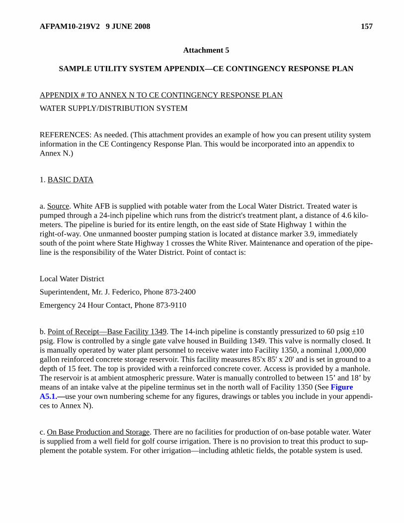
AFPAM10-219V2 9 JUNE 2008 157
Attachment 5
SAMPLE UTILITY SYSTEM APPENDIX—CE CONTINGENCY RESPONSE PLAN
APPENDIX # TO ANNEX N TO CE CONTINGENCY RESPONSE PLAN
WATER SUPPLY/DISTRIBUTION SYSTEM
REFERENCES: As needed. (This attachment provides an example of how you can present utility system information in the CE Contingency Response Plan. This would be incorporated into an appendix to Annex N.)
1. BASIC DATA
a. Source. White AFB is supplied with potable water from the Local Water District. Treated water is pumped through a 24-inch pipeline which runs from the district's treatment plant, a distance of 4.6 kilo-meters. The pipeline is buried for its entire length, on the east side of State Highway 1 within the right-of-way. One unmanned booster pumping station is located at distance marker 3.9, immediately south of the point where State Highway 1 crosses the White River. Maintenance and operation of the pipe-line is the responsibility of the Water District. Point of contact is:
Local Water District
Superintendent, Mr. J. Federico, Phone 873-2400
Emergency 24 Hour Contact, Phone 873-9110
b. Point of Receipt—Base Facility 1349. The 14-inch pipeline is constantly pressurized to 60 psig ±10 psig. Flow is controlled by a single gate valve housed in Building 1349. This valve is normally closed. It is manually operated by water plant personnel to receive water into Facility 1350, a nominal 1,000,000 gallon reinforced concrete storage reservoir. This facility measures 85'x 85' x 20' and is set in ground to a depth of 15 feet. The top is provided with a reinforced concrete cover. Access is provided by a manhole. The reservoir is at ambient atmospheric pressure. Water is manually controlled to between 15’ and 18’ by means of an intake valve at the pipeline terminus set in the north wall of Facility 1350 (See Figure A5.1.—use your own numbering scheme for any figures, drawings or tables you include in your appendi-ces to Annex N).
c. On Base Production and Storage. There are no facilities for production of on-base potable water. Water is supplied from a well field for golf course irrigation. There is no provision to treat this product to sup-plement the potable system. For other irrigation—including athletic fields, the potable system is used.

158 AFPAM10-219V2 9 JUNE 2008
2. CONSUMPTION AND STORAGE DATA
a. Average Daily Consumption: 1,750,000 gal. (See Figure A5.2.—use your own numbering scheme).
b. Storage Capacity: 1,615,000 gal.
(1) Facility 1350—Receiving Reservoir—810,000 gal.
(2) Facility 650—80’ Elevated Tank—700,000 gal.
(3) Facility 2205—75’ Tower—105,000 gal.
c. On Base Storage as a Percent of Daily Requirement:
d. Fire Protection Storage Requirement: 1,990,000 gal. (Refer to UFC 3-230-03A, Water Supply, and UFC 3-230-09A for information on calculating requirements. Calculations not shown.)
e. Fire Protection Storage Deficit: 1,990,000 - 1,615,000 = 375,000 gal.
3. RECEIVING POINT DATA. Facility 1351 is locally referred to as the “Water Point.” It is in fact a pumping station which transfers water from the receiving reservoir to the base distribution system. Facil-ity 1351 is manned on a 24-hour basis by utility operations personnel (two per shift—phone 32482/3/4). These personnel maintain a constant supply of potable product to the system at a pressure of 30 to 35 psi. Disinfection is accomplished prior to discharge into the system. A single-line schematic follows:
a. Pumps. The plant uses six Fairbanks Morse centrifugal pumps (two in suction and four in discharge) rated nominally at 400 gpm. Pumps are individually driven by Westinghouse direct coupled polyphase squirrel cage motors rated as follows (30 bhp @ 1150 rpm). Primary power is from base distribution.
b. Disinfection. Disinfection is provided by two Wallace and Tierivan Series 800 V-notch chlorinator units, serviced by a bank of four 1-ton containers continuously in service. Maximum daily use is 1000 lbs chlorine chemicals. Four 1-ton containers are kept in reserve at the plant. Base Supply maintains nine 1-ton containers on 30-day bench stock.
1,615,000 =92%
1,750,000

AFPAM10-219V2 9 JUNE 2008 159
c. Emergency Power. Emergency power is provided by a 60-kW EAID generator, pad mounted on the north side of Facility 1351 and connected to the plant power panel via an exterior junction box. Start and load transfer are manual. Sufficient fuel (DF-1) for 18 hours of operation is stored in the day tank and underground on side.
d. Spares. Spares are maintained at the plant. Spares listings are maintained at the plant and on file at the Production Control Center.
4. VULNERABILITY SUMMARY. White AFB is located astride a natural drainage divide of the Red and Yellow River basins. Approximately 75% of the 4,400 acre reservation drains naturally to the south-west into the Red River system. The northeast quadrant drains to the east toward the Yellow River basin. Primary hazards related to the potable water system derive from loss of system pressure and are as fol-lows:
a. Contamination. Loss of, or suspicion of loss of pressure in any portion of the system subjects the system to contamination by infiltration.
b. Fire Flow Requirements. In the event of power loss to the pumping equipment or interdiction of the system, fire protection flow requirements cannot be sustained when system pressures fall below 20 psi.
Figure A5.1. Single-Line Schematic.
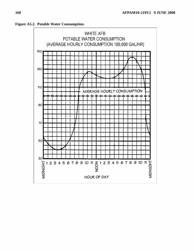
160 AFPAM10-219V2 9 JUNE 2008
Figure A5.2. Potable Water Consumption.