voltage/current-stabilized dc source
TRANSCRIPT

IMPORTANT NOTES:
1) This manual is valid for the following Model and associated serial numbers:
MODEL SERIAL NO. REV. NO.
2) A Change Page may be included at the end of the manual. All applicable changes andrevision number changes are documented with reference to the equipment serial num-bers. Before using this Instruction Manual, check your equipment serial number to identifyyour model. If in doubt, contact your nearest Kepco Representative, or the Kepco Docu-mentation Office in New York, (718) 461-7000, requesting the correct revision for your par-ticular model and serial number.
3) The contents of this manual are protected by copyright. Reproduction of any part can be
made only with the specific written permission of Kepco, Inc. Data subject to change without notice.
KEPCO® THE POWER SUPPLIER™
MODEL
OPERATOR’S MANUAL
KEPCO INC.
ORDER NO. REV. NO.
KEPCO, INC. 131-38 SANFORD AVENUE FLUSHING, NY. 11352 U.S.A. TEL (718) 461-7000 FAX (718) 767-1102email: [email protected] World Wide Web: http://www.kepcopower.com
ABC-DM SERIES
SWITCHING POWER SUPPLY
VOLTAGE/CURRENT-STABILIZED DC SOURCE
ABC-DM SERIESPOWER SUPPLY
©1996, KEPCO, INCP/N 243-0888


GETTING STARTEDSIMPLIFIED OPERATING INSTRUCTIONS
These instructions are a quick reference for getting started with Kepco’s ABC power supply. Formore detailed information you are encouraged to read the accompanying Operator’s Manual.
CONNECT THE LOAD. The Sense terminals must be connected for the powersupply to work. For local sensing use the links supplied on the barrier strip at the rear.For remote sensing, remove the links and make the 4-wire connections at your load. (See the Oper-ator’s manual for more information.)
CONNECT SOURCE POWER. The power supply accepts a wide range of sourcepower: 85-264V a-c, 47-63 Hz or 400Hz. The POWER switch turns the unit on and off. The powersupply is equipped with a grounded North American 2-blade plug. Overseas users may substitutetheir national plug; the chassis end is a standard 15A IEC connector.
LOCAL OPERATIONTHE ALPHANUMERIC DISPLAY (LCD). Operations are done from the keypadand observed on the LCD. Optimize LCD contrast by pressing MENU once, then press numbersuntil viewing is optimum. The LCD displays the actual output voltage and current and the operatingmode: Local or Remote and constant voltage (CV) or current (CC). and a blinking colon (:), or ablinking equal sign (=). Enter a command when you see a blinking colon (:), enter numbers whenyou see a blinking equal sign (=). Six keys have a dual function (command/number): the blinkingcolon (:) or equal sign (=) tells you which key function is effective.
USING THE KEYPAD. Use ENTER to accept numbers entered or execute a command.Use CLEAR if you make a mistake and don’t want to change the status quo. Valid entries areaccompanied by a short beep; invalid entries by a longer buzz. (The speaker can be disabled bypressing MENU three times and entering 0.)
OUTPUT SETTINGS. V SET sets output voltage; I SET sets output current. Dependingon the mode (CV or CC), one setting acts as a limit. (For example, in CC mode, V SET is the volt-age limit and I SET is the output current setting.) The operating mode (CC or CV) is determined bythe load combined with the V SET and I SET settings. The and keys can be used to increaseor decrease output voltage (CV mode) or current (CC mode) by the least amount possible (approxi-mately the maximum rating divided by 4000).
OUTPUT ON/OFF. (ON) enables programmed output settings to appear at the output(OFF) sets output voltage and current to zero and the LCD reads “Output is OFF’”
RESET. Use RESET to restore the power-on defaults (output on, V SET and I SET at zero, OVSET and OC SET at approximately 10% above rated output).
PROTECTION. OV SET and OC SET establish protection for overvoltage and overcurrentconditions. If the output attempts to exceed programmed OV SET or OC SET values, the LCD indi-cates which condition occurred, and the output goes to zero. RESET or cycle the power supply offand on to recover.
CALIBRATION. CALIB leads you through a digital calibration procedure (password pro-tected). The initial password is the voltage rating plus current rating (e.g., 1010 for ABC 10-10DM).You can change it with using the MENU. The previous calibration is saved and can be restored. Theoriginal factory calibration can also be restored. (See Section 4 of the Operator’s Manual.)
ABCCOND012703 A

STORAGE LOCATIONS. Forty locations are available to either save active settings orto establish a local program that can be sequenced (EDIT PROG). STORE lets you save the activeprogrammed settings (V SET, I SET, OV SET and OC SET). Just select a location (from 1 to 40).RECALL applies the V SET and I SET values previously stored.
LOCAL PROGRAMMING. The same forty locations are also available for local pro-gramming. Each location stores values for six parameters: output voltage, output current, overcur-rent protection, overvoltage protection, time duration (between 0.01 and 300 seconds) for theprogrammed parameters, and the address of the next memory location in the program. Local pro-grams are set up using EDIT PROG; a MEMORY LOCATION WORKSHEET table included in theOperator’s Manual helps you to program Kepco’s ABC.
Select the starting location and enter the desired values for each parameter. Use or key toscroll forward or backward to view the next parameter or memory location. Set the last address to 0for the program to run once and stop. If you want the program to cycle indefinitely, set the lastaddress to the starting address. After all parameters have been entered, use CLEAR or ENTER toexit EDIT PROG mode. To run the program one step at a time, press STEP, select a starting loca-tion, then press STEP to execute the next step. To run the program, press RUN and select the start-ing location. If the program is designed to cycle, press CLEAR or RESET to stop it. The TIME keyoffers a quick and easy way to change the time for any memory location without entering EDITPROG mode.
MENU FEATURES. Press MENU to scroll through the MENU functions. Press CLEAR toexit, enter number(s) and press ENTER to change a feature. The following features are included:
• Set LCD contrast: set from 1 to 9 for optimum viewing.• Set GPIB address select: Set from1 to 30• DCL Control: Allows DCL (Device Clear) to either set output to 0V or have no effect on out-
put voltage• Set speaker on/off: 0 to disable beeps and buzzes, 1 to enable.• Change password (required for calibration):. Enter old password, then the new pass-
word.• Restore previous calibration values: (See Section 4 of Operator’s Manual.)• View Model number, Serial number and firmware version (not changeable)• Set maximum values for V SET and I SET: To prevent damage to a sensitive load the
maximum output voltage and current can be reduced from the rated value to a user-selected maximum.
• Delay protection: To allow for large initial transients (e.g., from inductive loads), overvolt-age and overcurrent protection can be delayed about 8 seconds by entering a count (countof 30 is about one second, maximum count is 255). If an overvoltage or overcurrent condi-tion is still present at the end of the delay, protection trips the power supply off.
B ABCSVC012703
Declaration of Conformity
Application of Council directives: 73/23/EEC (LVD)89/336/EEC(EMC)93/68/EEC (CE mark)
Standard to which Conformity is declared:
EN61010-1: 1993 +A2: 1995
EN61326-1:1997
(Safety requirements for electrical equipment for measurement, control and laboratory use)
(Electrical equipment for measurement, control and laboratory use - EMC requirements)
Manufacturer's Name and Address: KEPCO INC.131-38 SANFORD AVENUE FLUSHING, N.Y. 11352 USA
Importer's Name and Address:
Type of Equipment: Power Supply
Model No.: ABC SERIES MODEL NUMBER]
Year of Manufacture:
I, the undersigned, declare that the product specified above, when used in accordance with the product instruction manual, complies with the requirements of the Low Voltage Directive 73/23/EEC and the EMC Directive 89/336/EEC, which forms the basis for application of the CE Mark to this product.
Place: KEPCO Inc.131-38 Sanford Ave.Flushing, N.Y.11352 USA
Date:
Saul Kupferberg(Full Name)
VP OF SALES(position)
REPRESENTATIVE COPY
228-1346 DC-ABC 012703 C/D Blank))


TABLE OF CONTENTS
SECTION PAGE
SECTION 1 - INTRODUCTION1.1 Scope of Manual ..................................................................................................................................... 1-11.2 General Description................................................................................................................................. 1-11.3 Specifications .......................................................................................................................................... 1-11.4 Local Control ........................................................................................................................................... 1-71.5 Remote Control ....................................................................................................................................... 1-71.6 Features .................................................................................................................................................. 1-71.6.1 Digital Calibration............................................................................................................................... 1-71.6.2 Overvoltage/Overcurrent Protection .................................................................................................. 1-71.6.3 Programmable Overvoltage/Overcurrent Delay................................................................................. 1-71.6.4 Non-volatile Storage of Programmed Sequences or Active Settings ................................................ 1-71.6.5 User-defined Voltage/Current Limits.................................................................................................. 1-81.7 Equipment Supplied ................................................................................................................................ 1-81.8 Accessories ............................................................................................................................................. 1-81.9 Safety ...................................................................................................................................................... 1-81.10 Ripple/Noise Measurement ..................................................................................................................... 1-9
SECTION 2 - INSTALLATION2.1 Unpacking and Inspection ....................................................................................................................... 2-12.2 Terminations and Controls ...................................................................................................................... 2-12.3 Source Power Requirements .................................................................................................................. 2-22.4 Cooling .................................................................................................................................................... 2-22.5 Preliminary Operational Check................................................................................................................ 2-22.6 Installation ............................................................................................................................................... 2-32.7 Wiring Instructions................................................................................................................................... 2-32.7.1 Safety Grounding............................................................................................................................... 2-42.7.2 Source Power Connections ............................................................................................................... 2-42.7.3 D-C Output Grounding....................................................................................................................... 2-42.7.4 Power Supply/Load Interface............................................................................................................. 2-52.7.5 Load Connection - General................................................................................................................ 2-52.7.6 Load Connection Using Local Sensing.............................................................................................. 2-62.7.7 Load Connection Using Remote Sensing.......................................................................................... 2-72.8 Operating Configuration .......................................................................................................................... 2-7
SECTION 3 - OPERATION3.1 General.................................................................................................................................................... 3-13.2 Local Mode Operation ............................................................................................................................. 3-13.2.1 Front Panel Keypad and LCD............................................................................................................ 3-13.2.1.1 Command Entry Status................................................................................................................ 3-13.2.1.2 Data Entry Status......................................................................................................................... 3-13.2.1.3 Display (LCD)............................................................................................................................... 3-13.2.1.4 Keypad Functions ........................................................................................................................ 3-23.2.2 Turning the Power Supply On............................................................................................................ 3-43.2.3 Setting Local Mode............................................................................................................................ 3-43.2.4 Adjusting LCD Contrast ..................................................................................................................... 3-53.2.5 Enabling/Disabling Audible Beeps..................................................................................................... 3-53.2.6 Enabling/Disabling DC Output Power................................................................................................ 3-53.2.6.1 Power Up Digital DC Output Control............................................................................................ 3-53.2.7 Reset ................................................................................................................................................. 3-53.2.8 Setting Output Voltage or Current ..................................................................................................... 3-53.2.9 Setting Overvoltage or Overcurrent Protection.................................................................................. 3-63.2.10 Changing Protection Delay................................................................................................................ 3-63.2.11 Changing Maximum Voltage or Current Value .................................................................................. 3-63.2.12 Storing Power Supply Output Settings .............................................................................................. 3-73.2.13 Recalling Stored Output Settings....................................................................................................... 3-73.2.14 Local Mode Programming of the Power Supply. ............................................................................... 3-7
ABC 012703 i

TABLE OF CONTENTS
SECTION PAGE
3.2.14.1 Creating or Modifying a Program (Program Edit Mode).............................................................. 3-73.2.14.1.1 Modifying Programmed Time Interval..................................................................................... 3-83.2.14.1.2 Time Interval Accuracy........................................................................................................... 3-83.2.14.2 Running a Program ..................................................................................................................... 3-83.2.14.3 Stepping Through a Program...................................................................................................... 3-83.2.14.4 Cycling a Program....................................................................................................................... 3-83.2.14.5 Running a Program Once ........................................................................................................... 3-103.2.14.6 Stopping a Program .................................................................................................................... 3-103.2.14.7 Stopping a Running Program...................................................................................................... 3-103.2.14.8 Sample Program ......................................................................................................................... 3-103.2.15 Calibration......................................................................................................................................... 3-103.3 Remote Mode Programming................................................................................................................... 3-113.3.1 IEEE 488 (GPIB) Bus Protocol ......................................................................................................... 3-113.3.2 DCL Control ...................................................................................................................................... 3-123.3.3 Changing the GPIB Address............................................................................................................. 3-133.3.4 ABC VISA Instrument driver ............................................................................................................. 3-133.3.4.1 VISA Instrument Driver Functions............................................................................................... 3-133.3.4.2 VISA Instrument Driver Programming Reference Manual .......................................................... 3-173.3.4.3 Demonstration Program Using the VISA Driver .......................................................................... 3-173.3.5 Programming Techniques to Optimize Power Supply performance ................................................. 3-193.3.5.1 Example of Proper Programming................................................................................................ 3-193.3.5.2 Explanation of Programming Techniques ................................................................................... 3-193.4 SCPI Programming................................................................................................................................. 3-203.4.1 SCPI Messages ................................................................................................................................ 3-203.4.2 Common Commands/Queries .......................................................................................................... 3-203.4.3 SCPI Subsystem Command/Query Structure................................................................................... 3-203.4.3.1 ABORt Subsystem ...................................................................................................................... 3-203.4.3.2 DISPlay Subsystem ................................................................................................................... 3-203.4.3.3 INITiate Subsystem..................................................................................................................... 3-203.4.3.4 LIST Subsystem.......................................................................................................................... 3-213.4.3.5 MEASure Subsystem .................................................................................................................. 3-213.4.3.6 OUTPut Subsystem .................................................................................................................... 3-213.4.3.7 Protection Subsystem ................................................................................................................. 3-213.4.3.8 STATus Subsystem .................................................................................................................... 3-213.4.3.9 TRIGger subsystem .................................................................................................................... 3-213.4.3.10 [SOURce:]VOLTage and [SOURce:]CURRent Subsystems ...................................................... 3-213.4.3.11 CALibrate Subsystem ................................................................................................................. 3-213.4.4 Program Message Structure ............................................................................................................. 3-223.4.4.1 Keyword ...................................................................................................................................... 3-223.4.4.2 Keyword Separator ..................................................................................................................... 3-243.4.4.3 Query Indicator............................................................................................................................ 3-243.4.4.4 Data............................................................................................................................................. 3-243.4.4.5 Data Separator............................................................................................................................ 3-243.4.4.6 Message Unit Separator ............................................................................................................. 3-253.4.4.7 Root Specifier.............................................................................................................................. 3-253.4.4.8 Message Terminator ................................................................................................................... 3-253.4.5 Understanding The Command Structure .......................................................................................... 3-253.4.6 Program Message Syntax Summary ................................................................................................ 3-263.4.7 SCPI Program Examples .................................................................................................................. 3-263.5 Operator Maintenance ............................................................................................................................ 3-27
SECTION 4 - CALIBRATION4.1 General ................................................................................................................................................... 4-14.2 Equipment Required ............................................................................................................................... 4-14.3 Calibration Procedures ........................................................................................................................... 4-14.3.1 Voltage Calibration............................................................................................................................ 4-24.3.2 Current Calibration............................................................................................................................ 4-24.4 Changing the Calibration Password ....................................................................................................... 4-3
ii ABC 012703
TABLE OF CONTENTS
SECTION PAGE
4.5 Restoring Previous Calibration Values.................................................................................................... 4-44.6 Restoring Factory Calibration Values...................................................................................................... 4-44.7 Setting Factory Calibration Values .......................................................................................................... 4-4
APPENDIX A - IEEE 488.2 COMMAND/QUERY DEFINITIONS
A.2 *CLS — Clear Status Command .......................................................................................................... A-1A.3 *ESE — Standard Event Status Enable Command ............................................................................... A-1A.4 *ESE? — Standard Event Status Enable Query .................................................................................... A-2A.5 *ESR? — Event Status Register Query ................................................................................................ A-2A.6 *IDN? — Identification Query ................................................................................................................. A-2A.7 *OPC — Operation Complete Command............................................................................................... A-2A.8 *OPC? — Operation Complete Query.................................................................................................... A-3A.9 *OPT? — Options Query ........................................................................................................................ A-3A.10 *RCL — Recall Command...................................................................................................................... A-3A.11 *RST — Reset Command ...................................................................................................................... A-4A.12 * SAV — Save Command ..................................................................................................................... A-5A.13 *SRE — Service Request Enable Command........................................................................................ A-5A.14 *SRE? — Service Request Enable Query.............................................................................................. A-5A.15 *STB? — Status Byte Register Query ................................................................................................... A-5A.16 *TRG — Trigger Command................................................................................................................... A-6A.17 *TST? — Self Test Query....................................................................................................................... A-6
APPENDIX B - SCPI COMMAND/QUERY DEFINITIONS
B.1 Introduction............................................................................................................................................. B-1B.2 ABORt Command................................................................................................................................... B-1B.3 CALibrate:CURRent:LEVel Command................................................................................................... B-2B.4 CALibrate:CURRent[:DATA] Command................................................................................................. B-3B.5 CALibrate:PASSword Command ........................................................................................................... B-3B.6 CALibrate:SAVE Command ................................................................................................................... B-4B.7 CALibrate:STATus Command................................................................................................................ B-4B.8 CALibrate:STATus? Query..................................................................................................................... B-4B.9 CALibrate:VOLTage:LEVel Command................................................................................................... B-4B.10 CALibrate:VOLTage[:DATA] Command................................................................................................. B-4B.11 CALibrate:ZERO Command................................................................................................................... B-5B.12 DISPlay:CONTrast Command................................................................................................................ B-5B.13 DISPlay:CONTrast? Query .................................................................................................................... B-5B.14 DISPlay:MODE Command ..................................................................................................................... B-5B.15 DISPlay:MODE? Query.......................................................................................................................... B-5B.16 DISPlay:TEXT Command....................................................................................................................... B-6B.17 DISPlay:TEXT? Query ........................................................................................................................... B-6B.18 INITiate[:IMMediate] Command ............................................................................................................. B-6B.19 INITiate:CONTinuous Command ........................................................................................................... B-6B.20 INITiate:CONTinuous Query .................................................................................................................. B-6B.21 INSTrument:STATe Command .............................................................................................................. B-6B.22 LIST:CURRent Command...................................................................................................................... B-7B.23 [SOUR:]LIST:CURRent? Query ............................................................................................................. B-7B.24 [SOUR:]LIST:CURRent:PROTect Command......................................................................................... B-7B.25 [SOUR:]LIST:CURRent:PROTect? Query.............................................................................................. B-8B.26 [SOUR:]LIST:DWELl Command............................................................................................................. B-8B.27 [SOUR:]LIST:DWELl? Query ................................................................................................................. B-8B.28 [SOUR:]LIST:INDex Command.............................................................................................................. B-8B.29 [SOUR:]LIST:INDex? Query................................................................................................................... B-8B.30 [SOUR:]LIST:SEQuence:NEXT Command............................................................................................ B-8B.31 [SOUR:]LIST:SEQuence:NEXT? Query................................................................................................. B-8B.32 [SOUR:]LIST:SEQuence:STARt Command........................................................................................... B-9B.33 [SOUR:]LIST:SEQuence:STARt? Query................................................................................................ B-9
ABC 012703 iii

TABLE OF CONTENTS
SECTION PAGE
B.34 [SOUR:]LIST:VOLTage Command......................................................................................................... B-9B.35 [SOUR:]LIST:VOLTage? Query.............................................................................................................. B-9B.36 [SOUR:]LIST:VOLTage:PROTect Command ......................................................................................... B-9B.37 [SOUR:]LIST:VOLTage:PROTect Query................................................................................................ B-9B.38 MEASure[:SCALar]:CURRent[:DC]? Query ........................................................................................... B-10B.39 MEASure[:VOLTage][:SCALar][:DC]? Query ......................................................................................... B-10B.40 OUTPut[:STATe] Command ................................................................................................................... B-10B.41 OUTPut[:STATe] Query.......................................................................................................................... B-10B.42 OUTPut:PROTection:DELay Command................................................................................................. B-10B.43 OUTPut:PROTection:DELay Query........................................................................................................ B-10B.44 PROGram:SELect:STATe Command..................................................................................................... B-11B.45 PROGram:SELect:STATe? Query ......................................................................................................... B-11B.46 READ[:SCALar]:CURRent[:DC]? Query................................................................................................. B-11B.47 READ[:VOLTage][:SCALar][:DC]? Query............................................................................................... B-11B.48 [SOURce:]CURRent[:LEVel][:IMMediate][:AMPlitude] Command.......................................................... B-11B.49 [SOURce:]CURRent[:LEVel][:IMMediate][:AMPlitude] Query................................................................. B-11B.50 [SOURce:]CURRent:[:LEVel]TRIGgered[:AMPlitude] Command........................................................... B-11B.51 [SOURce:]CURRent:[:LEVel]TRIGgered[:AMPlitude]? Query................................................................ B-12B.52 [SOURce:]CURRent:PROTection[:LEVel] Command ............................................................................ B-12B.53 [SOURce:]CURRent:PROTection[:LEVel]? Query ................................................................................. B-13B.54 [SOURce:]CURRent:PROTection:CLEar Command.............................................................................. B-13B.55 [SOURce:]CURRent:PROTection:TRIPped? Query............................................................................... B-13B.56 [SOURce:]CURRent:LIMit:HIGH Command........................................................................................... B-13B.57 [SOURce:]CURRent:LIMit:HIGH? Query................................................................................................ B-13B.58 [SOURce:]VOLTage[:LEVel][:IMMediate][:AMPlitude] Command.......................................................... B-13B.59 [SOURce:]VOLTage[:LEVel][:IMMediate][:AMPlitude]? Query............................................................... B-14B.60 [SOURce:]VOLTage:[:LEVel]TRIGgered[:AMPlitude] Command........................................................... B-14B.61 [SOURce:]VOLTage:[:LEVel]TRIGgered[:AMPlitude]? Query................................................................ B-14B.62 [SOURce:]VOLTage:LIMit:HIGH Command........................................................................................... B-14B.63 [SOURce:]VOLTage:LIMit:HIGH? Query................................................................................................ B-14B.64 [SOURce:]VOLTage:PROTection[:LEVel] Command ............................................................................ B-14B.65 [SOURce:]VOLTage:PROTection[:LEVel]? Query ................................................................................. B-15B.66 [SOURce:]VOLTage:PROTection:CLEar Command.............................................................................. B-15B.67 [SOURce:]VOLTage:PROTection:TRIPped? Query............................................................................... B-15B.68 [SOURce:]FUNCtion:MODE? Query ...................................................................................................... B-16B.69 STATus:OPERation:CONDition Query................................................................................................... B-16B.70 STATus:OPEReration:ENABle Command ............................................................................................. B-16B.71 STATus:OPEReration:ENABle? Query .................................................................................................. B-16B.72 STATus:OPERation[:EVENt] Query ....................................................................................................... B-16B.73 STATus:PRESet Command ................................................................................................................... B-17B.74 STATus:QUEStionable[:EVENt]? Query ................................................................................................ B-17B.75 STATus:QUEStionable:CONDition? Query ............................................................................................ B-18B.76 STATus::QUEStionable:ENABle Command........................................................................................... B-18B.77 STATus:QUEStionable:ENABle? Query................................................................................................. B-18B.78 SYSTem:ERRor[:NEXT]? Query ............................................................................................................ B-18B.79 SYSTem:ERRor:CODE? Query ............................................................................................................. B-18B.80 SYSTem:ERRor:CODE:ALL? Query ...................................................................................................... B-18B.81 SYSTem:KLOCk Command ................................................................................................................... B-20B.82 SYSTem:KLOCk? Query ........................................................................................................................ B-20B.83 SYSTem:LANGuage? Query.................................................................................................................. B-20B.84 SYSTem:LANGuage COMMAND........................................................................................................... B-20B.85 SYSTem:PASSword:CENable Command .............................................................................................. B-20B.86 SYSTem:PASSword:CDISable Command ............................................................................................. B-20B.87 SYSTem:PASSword:STATe? Query ...................................................................................................... B-20B.88 SYSTem:SECurity:IMMediate Command............................................................................................... B-21B.89 SYSTem:SET Command........................................................................................................................ B-21B.90 SYSTem:VERSion Query ....................................................................................................................... B-21
iv ABC 012703

LIST OF FIGURES
FIGURE TITLE PAGE
1-1 ABC Series Power Supply .......................................................................................................................... viii1-2 ABC Series Power Supply, Mechanical Outline Drawing............................................................................ 1-41-3 ABC Power Supply and RA 71 Rack Adapter, Outline Drawing ................................................................. 1-51-4 Two ABC Power SUpplies and RA 72 Rack Adapter, Outline Drawing ...................................................... 1-61-5 Ripple and Spike Measurement Cables...................................................................................................... 1-92-1 ABC Series Front Panel .............................................................................................................................. 2-12-2 ABC Series Rear Panel .............................................................................................................................. 2-12-3 LCD Power On Defaults.............................................................................................................................. 2-32-4 Grounded Load Connections, Local Sensing ............................................................................................. 2-62-5 Isolated Load Connections, Local Sensing................................................................................................. 2-62-6 Grounded Load Connections, Remote Sensing ......................................................................................... 2-72-7 Isolated Load Connections, Remote Sensing............................................................................................. 2-73-1 LCD Power On Defaults.............................................................................................................................. 3-43-2 ABC VISA Application, Virtual Panel .......................................................................................................... 3-183-3 Tree Diagram of SCPI Commands Used with ABC Power Supply ............................................................. 3-233-4 Message Structure...................................................................................................................................... 3-243-5 Typical Example Of ABC Power Supply Program Using SCPI Commands................................................ 3-27A-1 GPIB Commands ....................................................................................................................................... A-4B-1 Programming the Output............................................................................................................................ B-2B-2 Using Calibration Commands and Queries................................................................................................ B-3B-3 Using Display Commands.......................................................................................................................... B-5B-4 Using LIST Commands and Queries ......................................................................................................... B-7B-5 Programming Current ................................................................................................................................ B-12B-6 Programming Voltage ................................................................................................................................ B-15B-7 Using Status Commands and Queries....................................................................................................... B-17B-8 Using Sytem Commands and Queries....................................................................................................... B-21
ABC 012703 v/(vi Blank)


ABC 012703 vii
LIST OF TABLES
TABLE TITLE PAGE
1-1 Model Parameters .......................................................................................................................................1-11-2 Maximum Overvoltage and Overcurrent Settings .......................................................................................1-11-3 ABC Specifications .....................................................................................................................................1-21-4 Accessories .................................................................................................................................................1-81-5 Safety Symbols ...........................................................................................................................................1-82-1 Input/Output Pin Assignments for Remote Control .....................................................................................2-23-1 Key Functions .............................................................................................................................................3-23-2 Memory Location Worksheet ......................................................................................................................3-93-3 Sample Program (Model ABC 10-10DM) ....................................................................................................3-103-4 IEEE 488 (GPIB) Bus Interface Functions ..................................................................................................3-113-5 IEEE 488 (GPIB) Bus Command Mode Messages .....................................................................................3-123-6 IEEE 488 (GPIB) Bus Data Mode Messages ..............................................................................................3-123-7 ABC VISA Driver Functions ........................................................................................................................3-133-8 Rules Governing Shortform Keywords ........................................................................................................3-224-1 Factory Default Calibration Passwords .......................................................................................................4-3A-1 IEEE 488.2 Command/query Index ........................................................................................................... A-1A-2 Standard Event Status Enable Register and Standard Event Status Register Bits ................................... A-1A-3 Service Request Enable and Status Byte Register Bits ............................................................................. A-5B-1 SCPI Subsystem Command/query Index .................................................................................................. B-1B-2 Operation Condition Register, Operation Enable Register,
and Operation Event Register Bits .......................................................................................................... B-16B-3 Questionable Event Register, Questionable Condition Register
and Questionable Condition Enable Register Bits ..................................................................................B-17B-4 Error Messages .......................................................................................................................................... B-19B-5 Master Passwords ..................................................................................................................................... B-21

viii ABC 012703
FIGURE 1-1. ABC SERIES POWER SUPPLY

FIGURE 0-1.
SECTION 1 - INTRODUCTION
1.1 SCOPE OF MANUAL
This manual contains instructions for the installation and operation of the ABC series of 100Watt bench-top, voltage and current stabilized d-c power supplies manufactured by Kepco, Inc.,Flushing, New York, U.S.A.
1.2 GENERAL DESCRIPTION
The Kepco ABC Power Supply Series (Figure 1-1) consists of six single-output models as listedin Table 1-1. ABC Series Power Supplies can be operated from a wide range of a-c input powersources (85-265V a-c, 47 - 63Hz). Although ABC is a stand-alone, bench top design, rackmounting can also be accommodated by rack adapters available for standard 19-inch wideracks (see Figures 1-3 and 1-4). Load connections may be made either at front panel terminals,or at a barrier terminal strip located at the rear.
ABC Series Power Supplies employ high frequency switch-mode conversion and power factor cor-rection. ABC Power Supplies are full-range, automatic-crossover voltage/current stabilizers with afull rectangular output characteristic. The ABC is controlled digitally over the entire voltage/currentrange. Voltage and current are displayed on a two-line alphanumeric LCD display. Control of theABC can either be local (via the front panel keypad) or remote (via the IEEE 488.2 GPIB communi-cation bus) using SCPI commands.
1.3 SPECIFICATIONS
Table 1-1 below indicates parameters that vary for different ABC models; Table 1-2 lists theOvercurrent and Overvoltage Range for each model. Table 1-3 lists general specifications thatapply to all ABC models.
TABLE 1-1. MODEL PARAMETERS
MODEL NUMBER
d-c OUTPUT RIPPLE AND NOISE (mv) (See PAR. 1.10) EFFICIENCY
RANGE POWER 2x SOURCE FREQUENCY
SWITCHINGFREQUENCY SPIKE (50MHz) 100% LOAD
85-264V a-c
VOLTS AMPS WATTS TYP MAX TYP MAX TYP MAX % MIN
ABC 10-10DM 0-10 0-10 100 2 4 2 5 3 20 65%
ABC 15-7DM 0-15 0-7 105 3 7 3 8 4 20 66%
ABC 25-4DM 0-25 0-4 100 5 10 5 10 5 20 66%
ABC 36-3DM 0-36 0-3 108 7 15 7 15 7 20 67%
ABC 60-2DM 0-60 0-2 120 12 24 12 24 12 24 68%
ABC 125-1DM 0-125 0-1 125 25 50 25 50 25 50 70%
TABLE 1-2. MAXIMUM OVERVOLTAGE AND OVERCURRENT SETTINGS
MODEL NUMBER ABC 10-10DM
ABC 15-7DM
ABC25-4DM
ABC36-3DM
ABC60-2DM
ABC125-1DM
MAXIMUM OVERVOLTAGE SETTING 11V 17 27 39 65 137
MAXIMUM OVERCURRENT SETTING 11 7.7 4.4 3.3 2.2 1.1
ABCOPR012703 1-1

TABLE 1-3. ABC SPECIFICATIONS SPECIFICATION RATING/DESCRIPTION CONDITION
INPUT CHARACTERISTICSa-c Voltage nominal 100/120/220/240V a-c Single phase
range 85-264V a-c Wide range
Frequency nominal 50-60Hz >63Hz Input leakage current exceeds specificationsrange 47-63Hz (400Hz)
Current 85V a-c 1.8A
Maximum at100W output
120V a-c 1.3A
240V a-c 0.65A
264V a-c 0.60A
Initial turn-on surge 5A peak for <150 usec 85-264V a-c, 0-100% load
Power Factor (min) 120V 0.99100% load
240V 0.97
EMC immunity to: Radiated RF EN 61000-4-3 level 3
Magnetic Field EN 61000-4-8 level 4
Electrostatic discharge EN 61000-4-2 level 2: contact, level 3: 8KV air discharge
Conducted RF EN 61000-4-6 level 3
Electrical fast transient EN 61000-4-4 level 3
Surges EN 61000-4-5 level 4
EMC Emissions Conducted EN 55022 Class B 0.15-30 MHz
Radiated EN 55022 Class B 30-1000 MHz
Harmonics Conducted EN 61000-3-2 0-2 KHz
Leakage current 120V a-c <0.25mA Source frequency in47-63Hz range240V a-c <0.5mA
Circuit type PFC Flyback converter
Output Forward converter
Switching Frequency 100KHz
OUTPUT CHARACTERISTICSType of Stabilizer Automatic crossover Voltage/Current
Adjustment range 0 to 100% of rating Voltage/Current
Source effect Voltage <0.01% EO max Nominal ±15% of input voltageCurrent <0.01% IO max
Load effect Voltage <0.01% EO max0 to 100% load change
Current <0.02% IO max
Temperature effect Voltage <0.01% EO max Per degree C(0 to 50° C)Current <0.01% IO max
Time effect Voltage <0.01% EO max0.5-8.5 hours
Current <0.01% IO max
Error sense 0.5V per wire Voltage allowance
Isolation voltage 500V d-c or peak Output to ground
1-2 ABCOPR012703

OUTPUT CHARACTERISTICS (Continued)Programming time 2ms max 0-100%
Programming accuracy
Voltage <0.025% EO max
Current 0.1% IO max ABC 10-10DMABC 15-7DM
0.05% IO max ABC 25-4DM
0.025% IO maxABC 36-3DMABC 60-2DM
ABC 125-1DM
Readback/Displayaccuracy
Voltage <0.05% EO max
Current <0.1% IO max
Transient recovery to load change
Excursion <5% EO max 50-100% load changereturn to 1% EO maxRecovery <200 usec
Overshoot None Turn ON/OFF
Data entry Local 24 keypads Front panel
Remote GPIB SCPI commands
GENERAL (ENVIRONMENTAL) CHARACTERISTICSTemperature Operating 0° to +50° C No derating, 100% PO max
Operating +50° to +70° C Linear derating to 40% PO max
Storage -20° to +70° C
Humidity 0 to 95% RH Non condensingoperating & storage
Shock 20g, 11msec ±50%half sine
3-axes3 shocks each axis
Vibration 5-10Hz 10mm double amplitude
Non operating1 hour each axis
Altitude Sea level to 10,000 feet
Cooling Natural convection
PHYSICAL CHARACTERISTICSDimensions English 7.9” x 4.9” x 14” ±1/32” See Outline Drawing, Figure 1-2.
For rack mounting see Figures 1-3 and 1-4.
Metric 200.8 x 124.6 x 355.6 mm±0.8 mm
Weight English 11 lbs.Unpacked
Metric 5 Kg
A-C input connections
Front Panel ON/OFF switch
Rear Detachable IEC 320 type connector 3 wire fused
Output connections
Front 5 binding posts±Output, ±Sense, Ground
Rear 5 terminal barrier strips
Remote control programming
One standard GPIB connector
Rear,SCPI & IEEE 488.2 Commands
Digital display front panel
Voltage, current, mode, status, menu, program,
etc.
2 x 16 character alphanumeric LCD with LED backlight
TABLE 1-3. ABC SPECIFICATIONS (Continued)SPECIFICATION RATING/DESCRIPTION CONDITION
ABCOPR012703 1-3

FIGURE 1-2. ABC SERIES POWER SUPPLY, MECHANICAL OUTLINE DRAWING
1-4 ABCOPR012703

FIGURE 1-3. ABC POWER SUPPLY AND RA 71 RACK ADAPTER, OUTLINE DRAWING
ABCOPR012703 1-5

FIGURE 1-4. TWO ABC POWER SUPPLIES AND RA 72 RACK ADAPTER, OUTLINE DRAWING
1-6 ABCOPR012703
1.4 LOCAL CONTROL
Front panel keypad entries are utilized for setting and adjusting output voltage and currentunder local control. The keypad's keys are organized to either directly execute commands, or tointroduce a program that can either be run once or cycled. Calibration of the unit is facilitated bya password -protected, menu-driven procedure from the front panel.
1.5 REMOTE CONTROL
The ABC Power Supply can be remotely controlled directly via the IEEE 488.2 (GPIB) bus usingSCPI commands. All features available in local mode can also be accessed remotely. The unit isshipped with a VISA (Virtual Instrumentation Software Architecture) driver to facilitate remoteprogramming of the ABC Power Supply. The VISA translates function calls made in standard Clanguage to SCPI commands.
1.6 FEATURES
1.6.1 DIGITAL CALIBRATION
The ABC Power Supply contains no internal adjustments. Calibration is done entirely via thekeypad using digital entries and a calibrated DVM and precision shunt resistor. Calibrationinstructions appear on the front panel after a password is entered; previous calibration valuesare saved and can be restored if desired. The original factory calibration values can also berestored. (Refer to Section 4.)
1.6.2 OVERVOLTAGE/OVERCURRENT PROTECTION
Overvoltage and Overcurrent protection values can be individually programmed. The maximumvalues are listed in Table 1-2. Refer to PAR. 3.2.9.
1.6.3 PROGRAMMABLE OVERVOLTAGE/OVERCURRENT DELAY
Changing the output settings may cause large output transients (common with reactive loads)that can trip the overvoltage/overcurrent protection. The ABC can be programmed to delay trip-ping of overvoltage/overcurrent protection when output settings are changed to avoid inadvert-ent tripping. After the delay, the programmed overcurrent/overvoltage setting is effective.Protection can be delayed up to approximately 8 seconds after the output settings are changed.Refer to PAR. 3.2.10.
1.6.4 NON-VOLATILE STORAGE OF PROGRAMMED SEQUENCES OR ACTIVE SETTINGS
The ABC Power Supply contains 40 memory locations that can be used either to preprogram asequence of output values or to store the active settings. For programming sequences eachmemory location accommodates six parameters: output voltage, output current, Overvoltage,Overcurrent, Time (how long the parameters are in effect) and the next address in thesequence. Values are stored in the non-volatile memory, and are retained when the unit isturned off. Refer to PAR. 3.2.12.
The same 40 memory locations are also available to save the active programmed settings(V SET, I SET, OV SET and OC SET). The saved setting can be recalled by specifying thememory location.
ABCOPR012703 1-7

1.6.5 USER-DEFINED VOLTAGE/CURRENT LIMITS
The ABC output can be programmed not to exceed user-defined values. For example, the ABC10-10DM, which has a maximum capacity of 10V, 10A, can be limited to 5.5V, 1A for workingwith circuitry that might be damaged by higher levels. Once the limits are set, the power supplybecomes, in effect a 5.5V,1A supply and values exceeding the limit values will not be accepted.Refer to PAR. 3.2.11.
1.7 EQUIPMENT SUPPLIED
The unit is shipped with a standard Power Cord, IEC to 115 VAC (USA),
1.8 ACCESSORIES
Accessories for the ABC Power Supply are listed in Table 1-4.
1.9 SAFETY
There are no operator serviceable parts inside the case. Service must be referred to authorizedpersonnel. Using the power supply in a manner not specified by Kepco. Inc. may impair the pro-tection provided by the power supply. Observe all safety precautions noted throughout this man-ual. Table 1-5 lists symbols used on the power supply or in this manual where applicable.
TABLE 1-4. ACCESSORIES
ITEM FUNCTION PART NUMBER
Rack Adapter Accepts a single ABC power supply for installation in a 19-inch wide rack (see Figure 1-3). RA 71
Rack Adapter Accepts a two ABC power supplies for side by sided installation in a 19-inch wide rack (see Figure 1-4). RA 72
IEEE 488 Cable, (1 meter long) Connects ABC power supply to GPIB bus SNC 488-1
IEEE 488 Cable, (2 meter long) Connects ABC power supply to GPIB bus SNC 488-2
IEEE 488 Cable, (4 meter longs) Connects ABC power supply to GPIB bus SNC 488-4
Fuse Circuit Protection (Replacement of Fuse A2FS1 is authorized by service personnel only.)
IEC TYPE T, 3.15A, 250V a-c
TABLE 1-5. SAFETY SYMBOLS
SYMBOL Meaning
WARNING: RISK OF ELECTRIC SHOCK.
CAUTION: REFER TO REFERENCED PROCEDURE.
WARNING INDICATES THE POSSIBILITY OF BODILY INJURY OR DEATH.
CAUTION INDICATES THE POSSIBILITY OF EQUIPMENT DAMAGE.
!
1-8 ABCOPR012703
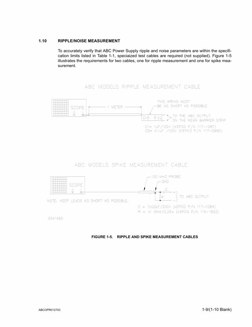
1.10 RIPPLE/NOISE MEASUREMENT
To accurately verify that ABC Power Supply ripple and noise parameters are within the specifi-cation limits listed in Table 1-1, speciaized test cables are required (not supplied). Figure 1-5illustrates the requirements for two cables, one for ripple measurement and one for spike mea-surement.
FIGURE 1-5. RIPPLE AND SPIKE MEASUREMENT CABLES
ABCOPR012703 1-9/(1-10 Blank)


SECTION 2 - INSTALLATION
2.1 UNPACKING AND INSPECTION
This instrument has been thoroughly inspected and tested prior to packing and is ready foroperation. After careful unpacking, inspect for shipping damage before attempting to operate.Perform the preliminary operational check as outlined in PAR. 2.5. If any indication of damage isfound, file an immediate claim with the responsible transport service.
2.2 TERMINATIONS AND CONTROLS
a) Front Panel: Refer to Figure 2-1 and Table 3-1.
b) Rear Panel: Refer to Figure 2-2 and Table 2-1.
FIGURE 2-1. ABC SERIES FRONT PANEL
FIGURE 2-2. ABC SERIES REAR PANEL
ABC 012703 2-1

2.3 SOURCE POWER REQUIREMENTS
This power supply operates from single phase a-c mains power over the specified voltage andfrequency ranges (Table 1-3) without any need for range selection.
2.4 COOLING
The power devices used within the power supply are maintained within their operating tempera-ture range by means of internal heat sink assemblies cooled by convection. Periodic cleaning ofthe power supply interior is recommended. If the power supply is located within a confined space,care must be taken that the ambient temperature, which is the temperature of the air immediatelysurrounding the power supply, does not rise above the specified limits (see Table 1-3).
2.5 PRELIMINARY OPERATIONAL CHECK
A simple operational check after unpacking and before equipment installation is advisable toascertain whether the power supply has suffered damage resulting from shipping.
Refer to Figures 2-1 and 2-3 for location of operating controls and electrical connections. Tables3-1 and 3-2 explain the functions of operating controls/indicators and keypad keys, respectively.
TABLE 2-1. INPUT/OUTPUT PIN ASSIGNMENTS FOR REMOTE CONTROL CONNECTOR PIN SIGNAL NAME FUNCTION
IEEE 488 PORT
J5
1 DI01 I/O Line
2 DI02 I/O Line
3 DI03 I/O Line
4 DI04 I/O Line
5 EOI End or Identify
6 DAV Data Valid
7 NRFD Not Ready for Data
8 NDAC Not Data Accepted
9 IFC Interface Clear
10 SRQ Service Request
11 ATN Attention
12 SHIELD Shield
13 DI05 I/O Line
14 DI06 I/O Line
15 DI07 I/O Line
16 DI08 I/O Line
17 REN Remote Enable
18 GND Ground (signal common)
19 GND Ground (signal common)
20 GND Ground (signal common)
21 GND Ground (signal common)
22 GND Ground (signal common)
23 GND Ground (signal common)
24 LOGIC GND Logic Ground
2-2 ABC 012703

1. With POWER switch set to off position, connect the power supply to source power.
2. With no load connected, set POWER switch to the ON position. Each time the unit is turnedon and an internal self-test is performed. If the test is successful the indications of step 3 arevisible.
3. The alphanumeric display (LCD) indicates the model and GPIB address. After approximately2 seconds, the display changes to the power on default values: Local mode, Constant Volt-age (CV) mode, 0.000V, 0.000A, output enabled, command entry status (see Figure 2-3).Overcurrent and Overvoltage protection are set to the maximum values (Table 1-2), but arenot displayed.
FIGURE 2-3. LCD POWER ON DEFAULTS
NOTE: Six keys with dual functions are labeled with both a command and a number. The com-mand label is referred to when the unit is in command entry status; the number isreferred to when the unit is in data entry status.
4. Press VSET key. Verify bottom line of LCD reads Vset nn (where nn = voltage setting).
5. Connect a digital voltmeter (DVM) to the (+) and (–) terminals at either the front or rear panel.
6. Use number keys to enter rated maximum voltage (e.g. for ABC 25-4DM, 25V is the ratedmaximum voltage) and press ENTER. Output voltage will be displayed at bottom left of LCD.
7. Use and keys as necessary to adjust output precisely to rated maximum voltage. Ver-ify DVM voltage reading agrees with displayed voltage on LCD within 0.01% of rated maxi-mum (see Table 1-3). If the LCD reads VsetMAX= (value), you are entering a value higherthan the maximum voltage setting; see PAR. 3.2.11.
2.6 INSTALLATION
A bail located on the bottom of the unit can be utilized to raise the front of the unit about twoinches for ease of accessing the front panel keypad and LCD display. For rack mounting, referto Figures 1-3 and 1-4.
2.7 WIRING INSTRUCTIONS
Interconnections between an a-c power source and a power supply, and between the powersupply and its load are as critical as the interface between other types of electronic equipment.If optimum performance is expected, certain rules for the interconnection of source, power sup-ply and load must be observed by the user. These rules are described in detail in the followingparagraphs.
Loc CV0.000A0.000V
NOTE: indicates blinking colon (:), Command Entry status indicates blinking equal sign (=), Data Entry status
ABC 012703 2-3

2.7.1 SAFETY GROUNDING
Local, national and international safety rules dictate the grounding of the metal cover and caseof any instrument connected to the a-c power source, when such grounding is an intrinsic part ofthe safety aspect of the instrument. The ground terminal of the source power connector (Figure2-2) is connected to the ABC chassis and the instructions below suggest wiring methods whichcomply with these safety requirements; however, in the event that the specific installation for thepower system is different from the recommended wiring, it is the customer's responsibility toensure that all applicable electric codes for safety grounding requirements are met.
2.7.2 SOURCE POWER CONNECTIONS
Source power is connected to the power supply via the three-wire power input cable supplied.See Table 1-3 for source power specifications.
2.7.3 D-C OUTPUT GROUNDING
Connections between the power supply and the load and sensing connections may, despite allprecautions such as shielding, twisting of wire pairs, etc., be influenced by radiated noise, or“noise pick-up”. To minimize the effects of this radiated noise the user should consider ground-ing one side of the power supply/load circuit. The success of d-c grounding requires carefulanalysis of each specific application, however, this recommendation can only serve as a generalguideline.
One of the most important considerations in establishing a successful grounding scheme is toavoid GROUND LOOPS. Ground loops are created when two or more points are grounded atdifferent physical locations along the output circuit. Due to the interconnection impedancebetween the separated grounding points, a difference voltage and resultant current flow issuperimposed on the load. The effect of this ground loop can be anything from an undesirableincrease in output noise to disruption of power supply and/or load operation. The only way toavoid ground loops is to ensure that the entire output/load circuit is fully isolated from ground,and only then establish a single point along the output/load circuit as the single-wire groundpoint.
The exact location of the “best” d-c ground point is entirely dependent upon the specific applica-tion, and its selection requires a combination of analysis, good judgement and some amount ofempirical testing. If there is a choice in selecting either the positive or negative output of thepower supply for the d-c ground point, both sides should be tried, and preference given to theground point producing the least noise. For single, isolated loads the d-c ground point is oftenbest located directly at one of the output terminals of the power supply; when remote error sens-ing is employed, d-c ground may be established at the point of sense lead attachment. In thespecific case of an internally-grounded load, the d-c ground point is automatically established atthe load.
The output binding posts of ABC Power Supplies are d-c isolated (“floating”) from the chassis inorder to permit the user maximum flexibility in selecting the best single point ground location.Output ripple specifications as measured at the output are equally valid for either side grounded.Care must be taken in measuring the ripple and noise at the power supply: measuring deviceswhich are a-c line operated can often introduce additional ripple and noise into the circuit.
There is, unfortunately, no “best” method for interconnecting the load and power supply. Individ-ual applications, location and nature of the load require careful analysis in each case. Ground-ing a single point in the output circuit can be of great importance. It is hoped that the preceding
2-4 ABC 012703

paragraphs will be of some assistance in most cases. For help in special applications or difficultproblems, consult directly with Kepco's Application Engineering Department.
2.7.4 POWER SUPPLY/LOAD INTERFACE
The general function of a voltage- or current-stabilized power supply is to deliver the rated out-put quantities to the connected load. The load may have any conceivable characteristic: it maybe fixed or variable, it may have predominantly resistive, capacitive or inductive parameters; itmay be located very close to the power supply output terminals or it may be a considerable dis-tance away. The perfect interface between a power supply and its load would mean that thespecified performance at the output terminals would be transferred without impairment to anyload, regardless of electrical characteristics or proximity to each other.
The stabilized d-c power supply is definitely not an ideal voltage or current source, and practicalinterfaces definitely fall short of the ideal. All voltage-stabilized power supplies have a finitesource impedance which increases with frequency, and all current-stabilized power supplieshave a finite shunt impedance which decreases with frequency. The method of interfacebetween the power supply output and the load must, therefore, take into account not only thesize with regard to minimum voltage drop, but the configuration with regard to minimizing theimpedance introduced by practical interconnection techniques (wire, bus bars, etc.). The seriesinductance of the load wire must be as small as possible as compared to the source inductanceof the power supply: although the error sensing connection to the load compensates for the d-cvoltage drop in the power leads, it cannot compensate for the undesirable output effects of thepower lead inductance. These lead impedances (both power and sensing leads) are especiallyimportant if the load: is constantly modulated or step-programmed; has primarily reactive char-acteristics; or where the dynamic output response of the power supply is critical to load perfor-mance.
2.7.5 LOAD CONNECTION - GENERAL
Load connections to the ABC power supply are achieved via the (+) and (–) binding postslocated on the front panel. A barrier strip is provided at the rear panel for connection to the load(system applications).
NOTE REGARDLESS OF OUTPUT CONFIGURATION, OUTPUT SENSE LINES MUST BECONNECTED FOR OPERATION.
1. OBSERVE POLARITIES: The OUTPUT +S sensing wire must be connected to theOUTPUT + load wire, and the OUTPUT –S sensing wire must be connected to theOUTPUT – load wire.
2. IF LOCAL SENSING IS USED, INSTALL LINKS (see Figures 2-4 and 2-5). Linksmay be installed at either the front or rear terminals, but not both (installing links at boththe front and rear will degrade power supply performance).
ABC 012703 2-5

2.7.6 LOAD CONNECTION USING LOCAL SENSING
Figure 2-4 shows a typical configuration using local sensing and a grounded load; Figure 2-5shows a typical configuration using local sensing with an isolated (“floating”) load.
FIGURE 2-4. GROUNDED LOAD CONNECTIONS, LOCAL SENSING
FIGURE 2-5. ISOLATED LOAD CONNECTIONS, LOCAL SENSING
2-6 ABC 012703
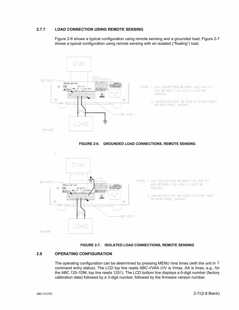
2.7.7 LOAD CONNECTION USING REMOTE SENSING
Figure 2-6 shows a typical configuration using remote sensing and a grounded load; Figure 2-7shows a typical configuration using remote sensing with an isolated (“floating”) load.
FIGURE 2-6. GROUNDED LOAD CONNECTIONS, REMOTE SENSING
.
FIGURE 2-7. ISOLATED LOAD CONNECTIONS, REMOTE SENSING
2.8 OPERATING CONFIGURATION
The operating configuration can be determined by pressing MENU nine times (with the unit in command entry status). The LCD top line reads ABC-VVAA (VV is Vmax, AA is Imax, e.g., forthe ABC 125-1DM, top line reads 1251). The LCD bottom line displays a 6-digit number (factorycalibration date) followed by a 3-digit number, followed by the firmware version number.
ABC 012703 2-7/(2-8 Blank)


SECTION 3 - OPERATION
3.1 GENERAL
This section explains how to operate the ABC Power Supply. The power supply can be operatedeither in Local mode using the front panel keypad and LCD, or in Remote mode using SCPIcommands via the GPIB bus. Operation in remote mode can be simplified by the use of theVISA driver supplied with the power supply.
Local mode operation includes a description of the interaction between the LCD and the frontpanel keypad. Each key of the front panel is described, with a reference to a paragraph detailingthe use of that key.
3.2 LOCAL MODE OPERATION
Local operation of the ABC Power Supply is accomplished via the 24 key keypad on the frontpanel. All indications are provided by the 2-line LCD.
3.2.1 FRONT PANEL KEYPAD AND LCD (SEE FIGURE 2-1)
The front panel keypad is comprised of 24 key, 13 dedicated to command functions, 5 dedicatedto data functions, and 6 keys that have both command and data functions When the power sup-ply is in command entry status the command functions are effective; when the power supply isin data entry status the data functions are effective.
3.2.1.1 COMMAND ENTRY STATUS
Indicated by blinking colon (:) on bottom line of LCD; the power supply is waiting for a commandto be entered; data will not be accepted (accompanied by brief audible buzz). The LCD indi-cates the actual voltage and current at the output terminals. When the output is disabled (LCDbottom line reads Output OFF), the power supply is in Command entry status even though theblinking colon is not visible.
NOTE: The blinking colon is indicated by in this manual.
3.2.1.2 DATA ENTRY STATUS
Indicated by blinking equal sign (=) on bottom line of LCD; the power supply is waiting for datato be entered. A command will not be accepted (accompanied by brief audible buzz). Enter newvalue (the key erases data entered). Press ENTER to accept new setting, or CLEAR to exitwithout changing setting.
NOTE: The blinking equal sign is indicated by in this manual.
3.2.1.3 DISPLAY (LCD)
The LCD is a 2-line display with a capacity of 16 characters per line. The information is gener-ally arranged as follows (information that does not follow this format is self-explanatory).
• Top left: Loc/Rem/Rwl Local/Remote/Keypad locked Status (See PAR. 3.2.3 )
• Top right CV/CC Constant voltage mode/constant currentmode
ABC 012703 3-1

• Bottom left:In command entry n.nnnV Output voltageIn data entry: (parameter) e.g. OVset if OV SET key was pressed.
• Bottom middle: Command entry statusData entry status
• Bottom right:In command entry n.nnnA Output currentIn data entry: n.nnn Present value of parameter, replaced by
data entered
3.2.1.4 KEYPAD FUNCTIONS
Keypad functions are listed in Table 3-1. Six keys have dual functions, depending on whetherthe power supply is in command entry status (waiting for a command to be entered), or dataentry status (waiting for a number to be entered). Command entry status is indicted by a blinkingcolon and data entry status is indicated by a blinking equal sign .
NOTE: Keys with dual functions are labeled with both a command and a number. The com-mand label is referred to when the unit is in command entry status; the number isreferred to when the unit is in data entry status.
TABLE 3-1. KEY FUNCTIONS
KEY POWER SUPPLY STATUS ACTIVE DESCRIPTION REFERENCE
PARAGRAPH
OUTPUTON/OFF Command Entry
If bottom line of LCD reads Output OFF, press to enable the output. If out-put is on (voltage and current measurements displayed on bottom line of LCD), press to disable the output.
3.2.6
V SET Command EntryPress to set output voltage. After V SET is pressed, previous setting is dis-played. Data entry required to enter new value of output voltage; press ENTER to accept displayed value.
3.2.8
I SET Command EntryPress to set output current. After I SET is pressed, previous setting is dis-played. Data entry required to enter new value of output current; press ENTER to accept displayed value.
3.2.8
LOCAL Command EntryIf the power supply is in remote mode, keypad is disabled except for LOCAL key. Press to enable keypad. If LCD reads KEYPAD LOCKED, The LOCAL key is disabled and can only be unlocked by remote operation.
3.2.3
RESET Command Entry
Press to restore the power on default values: CV mode, output voltage = 0, output current = minimum (1-2% of IOmax), output enabled, overvoltage and overcurrent values per Table 1-2. Also resets overvoltage or overcur-rent condition.
3.2.7
MENU Command Entry
Press to enter Menu commands: press repeatedly to scroll through Menu functions: (1) set LCD contrast, (2) GPIB address, (3) DCL Control, (4) Power-Up Digital DC Output on/off, (5) Speaker on/off, (6) Calibration password, (7) previous calibration values, (8) factory calibration values, (9) view firmware serial number, (10) set maximum voltage, (11) set maximum current, (12) protection delay. Press ENTER or RESET to exit Menu.
(1) 3.2.4, (2) 3.3.3,(3) 3.3.2, (4) 3.2.6.1(5) 3.2.5,(6) 4.4, (7) 4.5,(8) 4.6 (9) 2.8,(10, 11) 3.2.11(12) 3.2.10,
OV SET7
Command Entry Press to set overvoltage protection value. Data entry required to enter the overvoltage protection value; press ENTER to accept displayed value.
3.2.9
Data Entry Press to enter number 7. 3.2.1.2
3-2 ABC 012703

OC SET8
Command Entry Press to set overcurrent protection value. Data entry required to enter new overcurrent protection value; press ENTER to accept displayed value.
3.2.9
Data Entry Press to enter number 8. 3.2.1.2
CALIB9
Command Entry Press to enter Calibration status. Requires password entry; instructions appear on LCD.
4.3
Data Entry Press to enter number 9. 3.2.1.2
STORE Command EntryPress to store present values of output voltage and current and overvoltage and overcurrent protection. Data entry required to select memory location where values are to be stored
3.2.12
EDIT PROG Command EntryPress to select the starting memory location to be edited. Then use or
to view or modify the parameters of a specific memory location or to create a new program.
3.2.14.1
STEP4
Command Entry Press to select starting address of program to be executed one step at a time.
3.2.14.3
Data Entry Press to enter number 4. 3.2.1.2
TIME5
Command Entry Press to edit time value for specific memory location. Select memory loca-tion (data entry), then enter time value, 0.01 to 300 seconds (data entry).
3.2.14.1
Data Entry Press to enter number 5. 3.2.1.2
RUN6
Command Entry Press to run a program. Requires data entry to select starting location. Press ENTER to accept displayed value.
3.2.14.2
Data Entry Press to enter number 6. 3.2.1.2
RECALL Command Entry
Press to recall previously stored values of output voltage and current, and overvoltage and overcurrent protection. Data entry required to select mem-ory location containing values to be recalled; press ENTER to accept dis-played value.
3.2.13
CLEAR Data Entry Press to exit Data Entry status; any numbers entered are lost. Restores Command Entry status
3.2.8
1 Data Entry Press to enter number 1. 3.2.1.2
2 Data Entry Press to enter number 2. 3.2.1.2
3 Data Entry Press to enter number 3. 3.2.1.2
ENTER Data Entry Press to accept data entered and return to Command Entry status. 3.2.8
Command Entry
— In CV (constant voltage), press to decrease output voltage by increment equal to voltage resolution (≤.0.025% of EOmax).— In CC (constant current), press to decrease output current by increment equal to current resolution (≤.0.025% of IOmax).— In EDIT PROG status, changes the parameter displayed on LCD for a specific memory location and decrements memory location displayed on LCD.
3.2.8, 3.2.14.1
Data Entry Erases number to left, or decreases value shown (e.g. Display Contrast set-ting).
3.2.8
0 Data Entry Press to enter number 0. 3.2.1.2
( . ) Data Entry Press to enter decimal point 3.2.1.2
TABLE 3-1. KEY FUNCTIONS (CONTINUED)
KEY POWER SUPPLY STATUS ACTIVE DESCRIPTION REFERENCE
PARAGRAPH
ABC 012703 3-3

3.2.2 TURNING THE POWER SUPPLY ON
When the power supply is turned on, it performs a self-test and displays the status in the LCD.After completing the self-test the LCD first shows the power supply type, e.g., Kepco ABC10-10 GPIB addr. = nn, where nn is the GPIB address (factory default GPIB address = 6).TheLCD then shows the power on defaults (see Figure 3-1). The defaults are: output enabled, volt-age mode, output voltage set to zero, output current set to a minimum value (1-2% of IO max).Power on defaults also include setting maximum values for overcurrent and overvoltage protec-tion indicated in Table 1-2.
NOTE: The power supply can be programmed to power up with output set to OFF. See PAR.3.3.2 and Appendix B, PAR. B.89.
FIGURE 3-1. LCD POWER ON DEFAULTS
Depressing any key on the keypad during the power up sequence will cause the power supplyto enter the keypad test. To return to normal operation, follow the prompts, depressing keypadkeys as indicated on the LCD.
3.2.3 SETTING LOCAL MODE
When the power supply is turned on, it is automatically set to Local mode. If remote commandsare accepted over the GPIB bus, the power supply will automatically go into Remote mode (Remat the upper left of the LCD). Pressing the LOCAL key will restore Local mode. When in Remotemode, all keys except LOCAL are disabled.
The ABC incorporates a “keypad lockout” command which allows the LOCAL key to be dis-abled during remote operation, preventing inadvertent setting of the power supply to Localmode. When the keypad is locked, the LCD displays Rwl in place of LOC. If the keypad is
Command Entry
— In CV (constant voltage), press to increase output voltage by increment equal to voltage resolution (≤.0.025% of EOmax).— In CC (constant current), press to increase output current by increment equal to current resolution (≤.0.025% of IOmax).— In EDIT PROG status, changes the parameter displayed on LCD for a specific memory location and increments memory location displayed on LCD
3.2.8, 3.2.14.1
Data Entry Not used. —
TABLE 3-1. KEY FUNCTIONS (CONTINUED)
KEY POWER SUPPLY STATUS ACTIVE DESCRIPTION REFERENCE
PARAGRAPH
Loc CV0.000A0.000V
NOTE: indicates blinking colon (:), Command Entry status indicates blinking equal sign (=), Data Entry status
3-4 ABC 012703
locked, it must be unlocked either by a remote command (see Appendix B, PAR. B.81), orcycling the power supply off then on.
3.2.4 ADJUSTING LCD CONTRAST
With the power supply in command entry status , press MENU key. Press or key toincrease or decrease contrast for optimum viewing. The contrast can also be set directly byentering a number from 1 to 9. Press ENTER or CLEAR to exit menu.
3.2.5 ENABLING/DISABLING AUDIBLE BEEPS
With the power supply in command entry status , press MENU key five times. The top line indi-cates if the speaker is on or off (the factory default setting is speaker on). Enter 1 to enable thespeaker, or 0 to disable the speaker. Press ENTER or CLEAR to exit menu.
3.2.6 ENABLING/DISABLING DC OUTPUT POWER
When the power supply is turned on, the output is automatically enabled, and the bottom line ofthe LCD gives voltage and current measurements at the output. To disable the output, press thered OUTPUT ON/OFF key; the lower line of the LCD reads: Output OFF. When the output isdisabled, voltage and current are programmed to zero; the power supply remains in CommandEntry status. Pressing the OUTPUT ON/OFF key again enables the output: the previously pro-grammed values of voltage and current are restored and the LCD displays the mode (CV or CC)and actual values of output voltage and current.
3.2.6.1 POWER UP DIGITAL DC OUTPUT CONTROL
The output of the power supply can be programmed to be either enabled or disabled uponpower-up. With the power supply in command entry status (:_:_:), press the MENU key fourtimes. The top line indicates whether the Digital DC Output will be on (enabled) or off (disabled)upon power-up. Press 1 to enable the Digital DC Output upon power up. This sets the output tozero volt and current to the Power-up value. Press 0 to disable the output upon power up. PressCLEAR or RESET to exit menu and return to command entry status.
3.2.7 RESET
RESET overrides all other local commands to reset the power supply to the power on defaults:output enabled, voltage mode, output voltage set to zero, output current set to a minimum value(1-2% of IO max), overcurrent and overvoltage protection set to the maximum values per Table1-2. The power supply remains in command entry status.
3.2.8 SETTING OUTPUT VOLTAGE OR CURRENT
V SET and I SET set output voltage and current limit, respectively, when the unit is in constantvoltage (CV) mode and set voltage limit and output current, respectively, when the unit is in con-stant current (CC) mode. The mode (CV or CC) is determined by the load together with the pro-grammed settings. As long as the voltage across the load produces a current that is less than orequal to the I SET value, the unit operates in CV mode (voltage programmed to V SET value,current limited by I SET value). If the load changes to the point that current through the loadreaches the I SET value, the unit automatically enters CC mode (current programmed to I SETvalue, voltage limited by V SET value).
With the power supply in command entry status , press V SET (voltage) or I SET (current) keyto put the power supply in data entry status . The lower right side of the LCD shows the pro-grammed setting in effect when the key is pressed. Press ENTER or CLEAR to exit without
ABC 012703 3-5

changing setting. Enter new value (the key erases data just entered) and press ENTER toaccept new setting or CLEAR to exit witrhout changing setting.
With the power supply in command entry status , an alternative is to use (increase) or key (decrease) to change the output by the minimum increment (≤.0.025% of EOmax for volt-age, ≤.0.025% of IOmax for current). In CC mode, these keys control output current; in CV modethey control output voltage. The and keys have no effect after the maximum (or pro-grammed limit) has been reached.
If the value entered exceeds the maximum setting, the LCD bottom line flashes VsetMAX=nn Vor IsetMAX=n.n A where n.n is the maximum setting (see PAR.3.2.11). The unit returns to waiting for a value that does not exceed the maximum.
3.2.9 SETTING OVERVOLTAGE OR OVERCURRENT PROTECTION
With the power supply in command entry status , press OV SET (overvoltage) or OC SET(overcurrent) to put the power supply in data entry status . The lower right side of the LCDshows the programmed setting in effect when the key is pressed. Press ENTER or CLEAR toexit without changing setting. Enter new value and press ENTER to accept new setting (the key erases data just entered), or CLEAR to exit without changing setting. To recover from over-voltage or overcurrent condition, press RESET; this restores the power on defaults (see PAR.3.2.7).
3.2.10 CHANGING PROTECTION DELAY
The overvoltage and overcurrent protection normally trips immediately upon detection of anovervoltage/overcurrent condition. However, changing output settings (particularly with reactiveloads) large transients can cause inadvertent tripping of the protection. For this reason, trippingof the overvoltager/overcurrent protection can be delayed approximately 8 seconds after theoutput is changed.
With the power supply in command entry status , press MENU key twelve times. LCD readsProt. Delay Count nn where nn is the active setting. A count of 0 means no delay, acount of 255 (highest value) means approximately 8 seconds delay (a count of 30 provides adelay of 1 second).
3.2.11 CHANGING MAXIMUM VOLTAGE OR CURRENT VALUE
The maximum values of voltage and current are determined by the model, e.g., 25V and 4A forthe ABC 25-4DM. These values can be lowered by the user, e.g., to prevent inadvertent dam-age to a specific circuit under test. Changing the maximum values of the ABC 25-4DM to 10Vand 1A, effectively makes the unit a 10V 1A power supply.
With the power supply in command entry status , press MENU key ten (voltage) or eleven (cur-rent) times. The LCD reads New MAXIMUM Vset (or Iset) nn where nn is the maximumvalue setting to be changed. Press ENTER or CLEAR to exit menu without changing setting.Press number keys to enter new value and press ENTER. Press ENTER again to exit the menuand return to command status .
If a value is entered that is higher than the rated maximum for the power supply, the bottom lineof the LCD flashes Vset or Iset MAX = nn where nn is the rated maximum of the power sup-ply. The unit remains in data entry status waiting for a value equal to or less than the ratedmaximum. Press CLEAR to exit without changing the value.
3-6 ABC 012703
Once the maximum value has been changed, if a value higher than the new maximum isattempted to be programmed, the LCD flashes Vset (or Iset) MAX = nn where nn is the pro-grammed maximum.
NOTE: If the programmed output value is higher than the new maximum value establishedwith the MENU key, the output will be limited to the new maximum value.
3.2.12 STORING POWER SUPPLY OUTPUT SETTINGS
The programmed settings of voltage, current, overvoltage protection and overcurrent protectioncan be stored in one of the 40 memory locations available for local programming (see PAR.3.2.14).
With the power supply in command entry status , press STORE key. The LCD reads STOREmem nn where nn is the memory location where the settings are to be stored. Press ENTERor CLEAR to exit without changing setting. Enter memory location (from 1 to 40) and pressENTER. The programmed voltage, current, overvoltage protection and overcurrent protectionsettings in effect when ENTER is pressed are stored in the selected memory location. To recallstored settings, see PAR. 3.2.13
3.2.13 RECALLING STORED OUTPUT SETTINGS
With the power supply in command entry status , press RECALL. The LCD reads RECALLmem nn where nn is the memory location holding the settings to be retrieved. Press ENTERor CLEAR to exit without changing setting. Enter memory location (from 1 to 40) and pressENTER. The stored settings for voltage, current, overvoltage protection and overcurrent protec-tion replace the current values, and the unit returns to command entry status.
3.2.14 LOCAL MODE PROGRAMMING OF THE POWER SUPPLY.
Local mode programming offers the user 40 memory locations that can be used to program thepower supply. Each location defines values for output voltage, output current, overcurrent pro-tection, overvoltage protection, time duration (between 0.1 and 300 seconds) for the pro-grammed settings, and the address of the next memory location in the program.
3.2.14.1 CREATING OR MODIFYING A PROGRAM (PROGRAM EDIT MODE)
Creating a program and modifying an existing program are identical except that a program mod-ification requires only selected parameters to be changed rather than all new parameter values.With the power supply in command entry status , press EDIT PROG key. The top line indicatesthe STARTaddr. nn, where nn is one of 40 memory location. To select a different address,enter new value and press ENTER.
The top line of the LCD indicates the active memory location, e.g. ViewVAL Mem <n> where nis the memory location previously chosen. The bottom line of the LCD indicates the parameteron the left (Iset, Vset, OVset, OCset, TIMEval, NEXT STEP), the parameter’s value on theright, and data entry status in the middle. To modify time values see PAR.3.2.14.1.1.
Press ENTER to accept displayed value, or enter new value and press ENTER to accept newsetting (the LCD displays the next parameter). Press CLEAR to exit Program Edit mode withoutchanging value. Use or key to scroll forward (or backward) to view next (or previous)parameter or memory location. For a program to run once, then stop, see PAR. 3.2.14.6; tocycle a program continuously, see 3.2.14.4. After all program values have been set, pressCLEAR or ENTER to exit Program Edit mode. Setting up a program can be made easier by
ABC 012703 3-7

copying the Memory Location Worksheet (Table 3-2) and filling in the values before program-ming the power supply.
3.2.14.1.1 MODIFYING PROGRAMMED TIME INTERVAL
The TIME key offers a quick and easy way to change the time for any memory location. With thepower supply in command entry status , press TIME key. The unit displays TIME @ mem =01 indicating the current step to be changed. To change a different step, enter the step numberusing the numeric keys. To proceed, depress ENTER. The LCD displays TIMEval = nn wherenn is the time value set for the selected location. Press ENTER to accept displayed value, orenter new value (between 0.01 and 300 seconds) and press ENTER to accept new value orpress CLEAR to exit without changing value. The unit returns to command entry status . Referto PAR. 3.2.14.1.2 if accuracy of time values is important.
3.2.14.1.2 TIME INTERVAL ACCURACY
The accuracy of the time interval is +5% (specified time interval may be exceeded by a maxi-mum of 5%).
3.2.14.2 RUNNING A PROGRAM
With the power supply in command entry status , press RUN key. The LCD bottom line indi-cates the start address of the program. Press ENTER key to run the program starting with thataddress. To change the starting address, enter new value and press ENTER to run the program.Press CLEAR to exit without running the program
3.2.14.3 STEPPING THROUGH A PROGRAM
The STEP function is useful for examining a program that has just been created or edited beforerunning in real-time. With the power supply in command entry status , press STEP key. TheLCD bottom line indicates the start address of the program; press ENTER to begin stepping atthat address. To change the starting address, enter new value and press ENTER to begin step-ping at the new address, press CLEAR to exit without stepping through the program.
The LCD top line shows LOC to indicate local mode, aa bb where aa is the memory locationjust executed, bb is the NEXT STEP location, and shows CV (constant voltage) or CC (constantcurrent) to indicate the actual operating mode. The LCD bottom line shows the output voltageand current measurements for the location just executed, and indicates command status.Press STEP to execute location bb. The LCD will again display the location just executed, volt-age and current measurements, and the NEXT STEP location. Continue to press STEP to exe-cute the program one step at a time, or press CLEAR to exit Step function.
3.2.14.4 CYCLING A PROGRAM
To cycle a program, modify the program (see PAR. 3.2.14.1) and go to the last memory locationto be executed and set the NEXT STEP address to the Starting address, causing the program toloop and repeat indefinitely. For example, if the last location is 14, and the starting location is 05,press EDIT PROG, enter 14, then press ENTER. Press until LCD reads ViewVAL Mem14NEXT STEP . Enter 5 and press ENTER. When the program runs, it will start at location 05,continue to 14, then loop back to the location 05, and repeat indefinitely.
3-8 ABC 012703

TABLE 3-2. MEMORY LOCATION WORKSHEET
MEMORYLOCATION
I SET(Current)
(A)
V SET(Voltage)
(V)
OCset(Overcurrent Protection)
(A)
OV set(OvervoltageProtection)
(V)
TIMEval(0. to 300 Sec)
(Sec)
NEXT STEP(Next location
to execute)
1
2
3
4
5
6
7
8
9
10
11
12
13
14
15
16
17
18
19
20
21
22
23
24
25
26
27
28
29
30
31
32
33
34
35
36
37
38
39
40
ABC 012703 3-9

3.2.14.5 RUNNING A PROGRAM ONCE
To set up a program to stop after running once, modify the program (see PAR. 3.2.14.1) and goto the last memory location to be executed and set the NEXT STEP address to 0. For example,with the power supply in command entry status , press EDIT PROG. Enter the last memorylocation you want executed (e.g. 14), then press ENTER. Press key until LCD readsViewVAL Mem14 NEXT STEP . Enter 0 and press ENTER. The program will now stop aftermemory location 14 is executed. When the program stops, the power supply will continue toprovide the output specified by the last location (in the above example, location 14).
3.2.14.6 STOPPING A PROGRAM
To set up a program to stop after running once, set the NEXT STEP address of the last memorylocation to be executed to 0. For example, with the power supply in command entry status ,press EDIT PROG. Enter the last memory location you want executed (e.g. 14), then pressENTER. Press key until LCD reads ViewVAL Mem14 NEXT STEP . Enter 0 and pressENTER. The program will now stop after memory location 14 is executed.
3.2.14.7 STOPPING A RUNNING PROGRAM
There are three ways to stop a program that is running:
• Press CLEAR key: the program immeditately stops at the step (location) that was beingexecuted when the key was pressed. The power supply output remains at the valuesspecified by that step.
• Press RESET key: The program stops and power on defaults are restored (see PAR.3.2.7).
• Press OUTPUT ON/OFF key: the output is disabled (programmed to zero) and the pro-gram immeditately stops at the step (location) that was being executed when the keywas pressed. Pressing the OUTPUT ON/OFF key again restores the output to the val-ues specified by the step in effect when the program was stopped.
3.2.14.8 SAMPLE PROGRAM
Table 3-2 shows a sample program designed to cycle continuously; if the NEXT STEP value forlocation 3 is set to 00, the program will run once and stop.
3.2.15 CALIBRATION
See Section 4.
TABLE 3-3. SAMPLE PROGRAM (MODEL ABC 10-10DM)
MEMORYLOCATION
I SET(Current)
(A)
V SET(Voltage)
(V)
OCset(Overcurrent Protection)
(A)
OV set(OvervoltageProtection)
(V)
TIMEval(0. to 300)
(Sec)
NEXT STEP(Next location
to execute)
1 2.1 4.3 11 11 1.5 022 1.2 5.0 1.3 5.2 1.8 033 4.5 6.2 4.8 6.4 1.0 01
3-10 ABC 012703
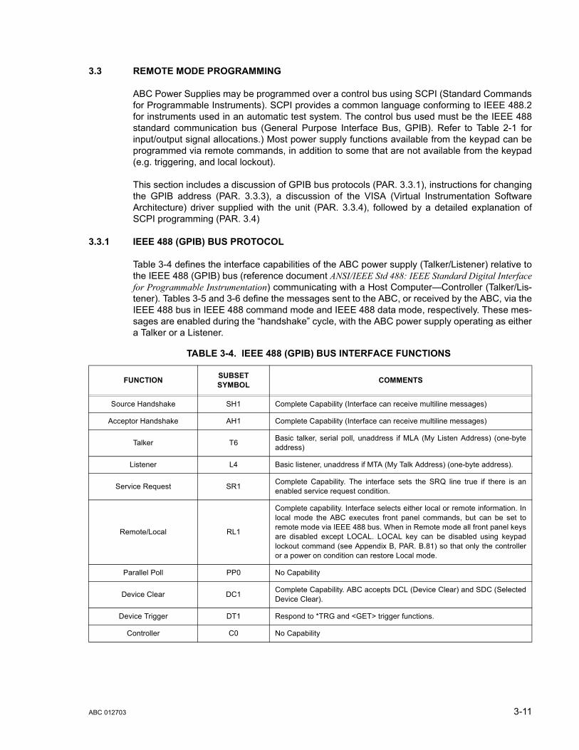
3.3 REMOTE MODE PROGRAMMING
ABC Power Supplies may be programmed over a control bus using SCPI (Standard Commandsfor Programmable Instruments). SCPI provides a common language conforming to IEEE 488.2for instruments used in an automatic test system. The control bus used must be the IEEE 488standard communication bus (General Purpose Interface Bus, GPIB). Refer to Table 2-1 forinput/output signal allocations.) Most power supply functions available from the keypad can beprogrammed via remote commands, in addition to some that are not available from the keypad(e.g. triggering, and local lockout).
This section includes a discussion of GPIB bus protocols (PAR. 3.3.1), instructions for changingthe GPIB address (PAR. 3.3.3), a discussion of the VISA (Virtual Instrumentation SoftwareArchitecture) driver supplied with the unit (PAR. 3.3.4), followed by a detailed explanation ofSCPI programming (PAR. 3.4)
3.3.1 IEEE 488 (GPIB) BUS PROTOCOL
Table 3-4 defines the interface capabilities of the ABC power supply (Talker/Listener) relative tothe IEEE 488 (GPIB) bus (reference document ANSI/IEEE Std 488: IEEE Standard Digital Interfacefor Programmable Instrumentation) communicating with a Host Computer—Controller (Talker/Lis-tener). Tables 3-5 and 3-6 define the messages sent to the ABC, or received by the ABC, via theIEEE 488 bus in IEEE 488 command mode and IEEE 488 data mode, respectively. These mes-sages are enabled during the “handshake” cycle, with the ABC power supply operating as eithera Talker or a Listener.
TABLE 3-4. IEEE 488 (GPIB) BUS INTERFACE FUNCTIONS
FUNCTION SUBSET SYMBOL COMMENTS
Source Handshake SH1 Complete Capability (Interface can receive multiline messages)
Acceptor Handshake AH1 Complete Capability (Interface can receive multiline messages)
Talker T6 Basic talker, serial poll, unaddress if MLA (My Listen Address) (one-byteaddress)
Listener L4 Basic listener, unaddress if MTA (My Talk Address) (one-byte address).
Service Request SR1 Complete Capability. The interface sets the SRQ line true if there is anenabled service request condition.
Remote/Local RL1
Complete capability. Interface selects either local or remote information. Inlocal mode the ABC executes front panel commands, but can be set toremote mode via IEEE 488 bus. When in Remote mode all front panel keysare disabled except LOCAL. LOCAL key can be disabled using keypadlockout command (see Appendix B, PAR. B.81) so that only the controlleror a power on condition can restore Local mode.
Parallel Poll PP0 No Capability
Device Clear DC1 Complete Capability. ABC accepts DCL (Device Clear) and SDC (SelectedDevice Clear).
Device Trigger DT1 Respond to *TRG and <GET> trigger functions.
Controller C0 No Capability
ABC 012703 3-11
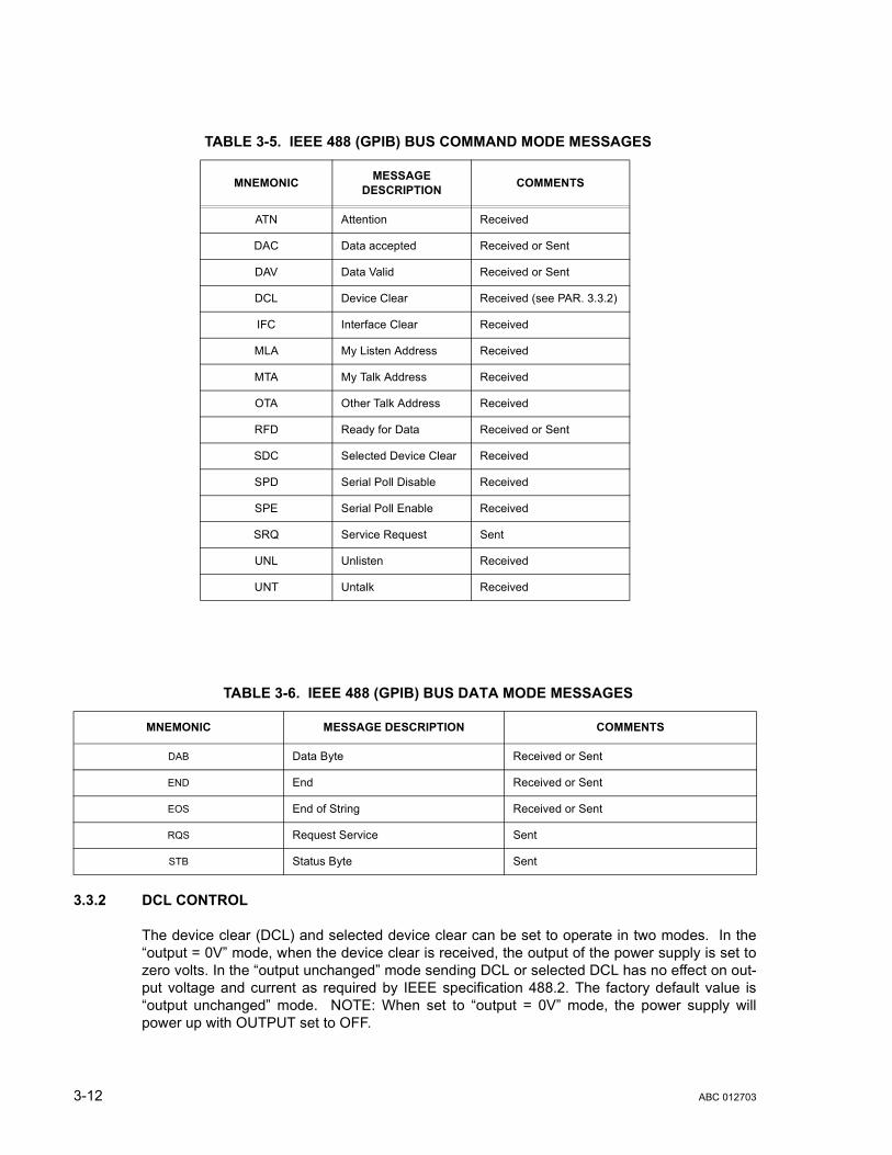
3.3.2 DCL CONTROL
The device clear (DCL) and selected device clear can be set to operate in two modes. In the“output = 0V” mode, when the device clear is received, the output of the power supply is set tozero volts. In the “output unchanged” mode sending DCL or selected DCL has no effect on out-put voltage and current as required by IEEE specification 488.2. The factory default value is“output unchanged” mode. NOTE: When set to “output = 0V” mode, the power supply willpower up with OUTPUT set to OFF.
TABLE 3-5. IEEE 488 (GPIB) BUS COMMAND MODE MESSAGES
MNEMONIC MESSAGE DESCRIPTION COMMENTS
ATN Attention Received
DAC Data accepted Received or Sent
DAV Data Valid Received or Sent
DCL Device Clear Received (see PAR. 3.3.2)
IFC Interface Clear Received
MLA My Listen Address Received
MTA My Talk Address Received
OTA Other Talk Address Received
RFD Ready for Data Received or Sent
SDC Selected Device Clear Received
SPD Serial Poll Disable Received
SPE Serial Poll Enable Received
SRQ Service Request Sent
UNL Unlisten Received
UNT Untalk Received
TABLE 3-6. IEEE 488 (GPIB) BUS DATA MODE MESSAGES
MNEMONIC MESSAGE DESCRIPTION COMMENTS
DAB Data Byte Received or Sent
END End Received or Sent
EOS End of String Received or Sent
RQS Request Service Sent
STB Status Byte Sent
3-12 ABC 012703

To change the DCL mode the unit must be in command entry mode , then depress the MENUkey three times. The top line of the display will show the current setting: either DCL setsOUTP=0V or DCL = OUTP UNCHNG. The bottom line of the display reads depress 1 totoggle. Depressing 1 toggles the DCL mode and updates the displayed message. Depressingthe RESET key leaves the mode unchanged. Depressing 0, ENTER, or MENU updates the DCLmode and displays the next selection.
3.3.3 CHANGING THE GPIB ADDRESS
When the power supply is in local mode, command entry status , press MENU key twice. Thetop line of the LCD indicates the current GPIB address. Enter new value and press ENTER toaccept new setting, or CLEAR to exit without changing setting.
3.3.4 ABC VISA INSTRUMENT DRIVER
The VISA instrument driver supplied with the ABC Power Supply is provided to simplify pro-gramming with a VISA compatible GPIB controller. Included on the diskette are:
• source code (C) for all VISA functions (kp_abc.c)
• a complete programming reference manual (kp_abc.doc)
• a sample application of the VISA functions (written in C) which can be used to programone or more ABC power supplies using a virtual front panel observed on a computermonitor (kp_appl.c)
Although the software drivers supplied by Kepco are VISA compliant, they also require theinstallation of the proper VISA driver from your GPIB card supplier. Many vendors supply thissoftware with the hardware; National Instruments (http://www.natinst.com) has the driver fortheir cards available on the internet at a file transfer site (ftp://ftp.natinst.com — find the folderfor suppport and VISA drivers).
3.3.4.1 VISA INSTRUMENT DRIVER FUNCTIONS
Kepco’s ABC VISA instrument driver provides programming support for Kepco’s ABC PowerSupply (VISA I/O). It contains functions for opening, configuring, taking measurements from,and closing the instrument. To successfully use this module, the instrument must be connectedto the GPIB and the GPIB address supplied to the initialize function must match the GPIBaddress of the instrument.
Table 3-7 lists the functions that are available.
TABLE 3-7. ABC VISA DRIVER FUNCTIONS
Purpose Function Name Description
INITIALIZE FUNCTION
Initialize KpAbc_init Initializes the instrument and sets it to a default configuration.
APPLICATION FUNCTIONS — This class of functions contains high-level test and measurement routines. These functions call other instrument driver functions to configure, start, and get readings from the instrument.
Set and Measure KpAbc_ApplicSetMeas Used to either set and read back, or just read back the output voltage, current and operating mode of the power supply
ABC 012703 3-13

Get/Set Memory Value KpAbc_GetSetListValue This function can either get or set the values stored in any one of the 40 available memory locations. Six parameter values can be stored in any one of the 40 locations: voltage level, current level, overvoltage level, overcurrent level, duration of the setting (if used in a program) and next memory address (if used in a program). Depending on the slide selec-tion position, and the value of get/set switch, one of these values is read or set. The values are checked against the maximum acceptable values for the corresponding power supply.
CONFIGURATION FUNCTIONS — This class of functions configures the instrument by setting system configuration parameters.
Set Program Start Address
KpAbc_SetStartAddr Sets the memory start address for the program chain. The program chain can also be executed in local mode. The start memory address range is from 1 to 40.
Get Program Start Address
KpAbc_GetStartAddr Gets the memory start address for the program chain. The program chain can also be executed in local mode. The start memory address range is from 1 to 40.
Set Maximum Limit Value
KpAbc_SetMaxLimValue Sets the temporary voltage limit or current limit of the power supply. The limit reduces the output range of the power supply. For example, the output voltage range of a 0 to 10V power supply can be limited to the range of 0 to 5.25V by setting the voltage limit to 5.25V.
Get Minimum or Maxi-mum Value
KpAbc_GetMinMaxValue Gets the minimum or the maximum output voltage, output current, overvoltage level, or overcurrent level of the power supply depending on the min_max switch and slide selection position.
Set Trigger Voltage and Current
KpAbc_SetTrig_Volt_Curr Sets the trigger voltage and trigger current at the same time
Set Trigger Value KpAbc_SetTrigValue Sets the trigger voltage or trigger current level, depending on the switch position.
Get Trigger Value KpAbc_GetTrigValue Gets the trigger voltage or the trigger current level, depending on the switch position.
Set Overvoltage and Overcurrent
KpAbc_Set_OVvolt_OVcurr Sets both the overvoltage and overcurrent values.
Set Protection Delay KpAbc_setProtDelay Sets the protection delay: the delay between the moment the output voltage and current are changed and the moment the overvoltage and overcurrent protections are enabled.
Get Protection Delay KpAbc_getProtDelay Displays the protection delay count for the power supply. A count of 30 represent ~ 1 second. The protection delay is the delay between the moment the output voltage and current are changed and the moment the overvoltage and overcurrent protections are enabled.
ACTION/STATUS FUNCTIONS — This class of functions executes commands and queries. It also provides functions which allow the user to determine the current status of the instrument.
Set Voltage and Current KpAbc_Set_Volt_Curr Sets the output voltage and current at the same time.
Set Value KpAbc_SetValue Sets the output voltage, the output current, the overvoltage level, or the overcurrent level of the power supply, depending on the slide selection position. The values are checked against the maximum acceptable val-ues for the corresponding power supply.
Get Value KpAbc_GetValue Gets the output voltage, the output current, the overvoltage level, or the overcurrent level of the power supply depending on slide selection position.
Trigger KpAbc_Trig Triggers the instrument once. The output will go to the trigger voltage and current values.
Measure Output Value KpAbc_MeasValue Measures the value of output voltage or current depending on the switch position.
Get Source Mode KpAbc_GetSourceMode Gets the operating mode of the power supply.
TABLE 3-7. ABC VISA DRIVER FUNCTIONS (CONTINUED)
Purpose Function Name Description
3-14 ABC 012703

Output On/Off KpAbc_OutputOnOff Sets the output on or off.
Get Output Status KpAbc_getOutputState Returns the output status (on or off).
Get Protection Status KpAbc_getProtectionStatus Gets the status of overvoltage or overcurrent protection (triggered or not triggered).
Clear Protection KpAbc_clearProtection Clears the overvoltage or overcurrent protection.
Abort Measurement KpAbc_abortMeas Sends the abort command.
Beep KpAbc_beep The selected ABC power supply will emit a beep.
DATA FUNCTIONS — This class of functions transfers data to or from the instrument.
Set Memory Index KpAbc_SetIndex Sets the index pointer to one of the 40 available memory locations The subsequent memory value changes will affect the memory location pointed to by the index pointer.
Get Memory Index KpAbc_GetIndex Gets the value of the index pointer.
Set Memory Value KpAbc_SetListValue Depending on the slide selection position, this function sets the value of the specified parameter (voltage level, current level, overvoltage level, overcurrent level, time value, next memory address value) for the memory location pointed to by the index pointer.
Get Memory Value KpAbc_GetListValue Depending on the slide selection position, this function gets the value of the specified parameter (voltage level, current level, overvoltage level, overcurrent level, time value, next memory address value) for the memory location pointed to by the index pointer.
Save/Recall Settings KpAbc_SaveRecSet Saves the current settings to the selected memory location or restores previously stored settings from a memory location. The memory loca-tion range is from 1 to 40.
UTILITY FUNCTIONS — This class of functions provides lower level functions to communicate with the instrument and to change instrument parameters.
Identify Power Supply KpAbc_identify Returns the full message returned by the power supply to the *IDN? query. This message contains four fields: manufacturer, power supply type, serial number and firmware version.
Revision Query KpAbc_RevisionQuery Returns the revision numbers of the instrument driver and instrument firmware version from the *idn? query. This instrument driver's Revision Number is "Rev 1.0, 9/95, CVI 3.1" and the ABC firmware version is Firmware Version "1.0". This data is necessary when requesting techni-cal support.
Model Query KpAbc_ModelQuery Return the model number of the ABC power supply.
Serial Number Query KpAbc_SerialnQuery Returns the serial number of the ABC power supply. The serial number is extracted from the answer to the *idn? query.
Query SCPI Version KpAbc_GetScpiVersion Returns the power supply answer to the Query SCPI Version com-mand. Checks the Standard Commands for Programmable Instru-ments (SCPI) language version.
Set/Reset Keypad Lock KpAbc_setResetKeybLock Locks or unlocks keypad operation. Used to prevent changing the set-tings of the power supply from the local keypad.
Keypad Lock Status KpAbc_keybLockStat Return the status of the local keypad access: 0 if local access enabled; 1 if local access is disabled.
Display Text KpAbc_display Configures the front panel display of the instrument. In normal mode the values measured at the output of the power supply are displayed. In text mode a user defined string can be displayed on the second row of the display.
Get Display Text KpAbc_getDisplay Gets the string which is displayed on the second line of the display.
Get Display Contrast KpAbc_getContrast Gets the contrast value of the front panel display of the instrument (between 0.1 and 0.9).
TABLE 3-7. ABC VISA DRIVER FUNCTIONS (CONTINUED)
Purpose Function Name Description
ABC 012703 3-15

Set Display Contrast KpAbc_setContrast Configures the contrast of front panel display of the instrument (value between 0.1 and 0.9).
Write To Instrument KpAbc_writeInstrData This function writes commands and queries to the instrument to modify parameters and query device settings.
Read Instrument Data KpAbc_readInstrData This function reads data from the instrument's output buffer and returns it to the specified variable in memory. Because the instrument may return both numeric and text data in response to queries, this function returns the data in string format. NOTE: If valid data is not available at the instrument's output buffer when this function is called, the instru-ment will hang up and the function will not return until it times out. If the time-out is disabled,` this function will hang indefinitely and it may be necessary to reboot the computer to break out.
Reset KpAbc_psReset Resets the instrument to a known state and sends initialization com-mands to the instrument.
Self-Test KpAbc_selfTest Runs the instrument's self test routine and returns the test result(s).
Error-Query KpAbc_errorQuery Reads an error code from the instrument's error queue.
Error Message KpAbc_errorMessage Takes the Status Code returned by the instrument driver functions, interprets it and returns it as a user readable string.
Calibration Status On/Off KpAbc_CalStatus Used to enter or exit the calibration state. To enter the calibration state a 4 digits password is required. When the instrument is shipped from the factory the calibration password is the 4 digit model number. The password protects the instrument against unauthorized calibrations.
Calibration Mode KpAbc_CalMode Allows the user to select the calibration mode (either voltage or current calibration) and also allows selection of 0 (min) or full scale (max) cali-bration.
Calibration DigPot KpAbc_CalDigPot Allows a more accurate full scale calibration in both voltage or current mode. Moving the digital potentiometer allows the user to approach the nominal full scale value of the corresponding power supply. This is a coarse adjustment for the full scale value which must be followed by a fine adjustment done with the Calibration Output function.
Calibration Output KpAbc_CalOutput Allows the user to perform the power supply calibration in both voltage or current mode. By moving the digital to analog converter the number of LSB's specified in the repeat count, the user can approach the 0 or full scale value of the corresponding power supply. This is a fine adjust-ment for the 0 or full scale value. The user can specify a repeat count between 1 and 9 in order to avoid having to repeat sending the com-mand
Calibration Zero KpAbc_CalZero Used to zero the output of the power supply before switching from volt-age calibration to current calibration (to allow a calibration resistor to be connected between the power supply output terminals.
Calibration Save KpAbc_CalSave Stores the calibration results in the nonvolatile calibration memory of the instrument.
Security Code KpAbc_CalCode Allows the user to change the password to prevent accidental or unau-thorized calibrations of the instrument. The password is stored in non-volatile memory, and does not change when power has been off or after a reset. To change the password, the instrument must already be in calibration status, ensuring that the user knows the current pass-word. If the password is lost, call the factory for support.
Close KpAbc_close This function takes the instrument off-line.
TABLE 3-7. ABC VISA DRIVER FUNCTIONS (CONTINUED)
Purpose Function Name Description
3-16 ABC 012703

3.3.4.2 VISA INSTRUMENT DRIVER PROGRAMMING REFERENCE MANUAL
A programming reference manual is supplied on the VISA driver diskette (file kp_abc.doc). Itdescribes each function in Kepco’s ABC Power Supply (VISA I/O). The functions are listed inalphabetical order with a description of the function, the C syntax of the function, a description ofeach parameter, and possible error codes. The sample application program included on the dis-kette can also be referenced and used as a programming guide, since it is debugged and illlus-trates successful programming techniques.
Error codes are returned as the return value of each instrument driver function. A programshould examine this value after each call to an instrument driver function to determine if anyerror occurred. Possible error codes and their meanings are listed with the corresponding instru-ment driver function.
3.3.4.3 DEMONSTRATION PROGRAM USING THE VISA DRIVER
The demonstration program is intended to illustrate the use of the VISA functions included withthe ABC power supply. The program can be used as is, or used as a starting point for a customuser-designed program. The source file (kp_appl.c) is included on the VISA driver diskette. Thedemonstration program is installed under Windows by running SETUP.EXE. The program canbe used to program and view the virtual front panels of up to 10 ABC Power Supplies. After theprogram is installed, double click on kepcoabc.exe to run the program.
You must enter the GPIB address of the ABC power supply to connect to the VISA interface.Once you are connected, you will see the virtual front panel (Figure 3-2, upper left).
The virtual front panel can show all power supply parameters simultaneously, without the havingto execute local controls and read the corresponding display. The virtual panel is a real-time dis-play of output values and programmed parameters. All local functions are also available fromthe virtual panel. The virtual panel is shown at the upper left of Figure 3-2; additional windowsfor Protections, Limits, Program Memories (below the panel), Edit Program Memory, Program,Display Change, and Display message (To the right of the panel) are also illustrated.
At the top of the panel, the Mode indicators light to indicate whether the power supply is operat-ing in either CV (constant voltage) or CC (constant current) mode. At the top left and right areanalog meters that read actual output voltage and current; a Display window at the center pro-vides a more precise digital readout of actual output voltage and current. Above the display win-dow, between the two analog meters, is the Output button which either applies the programmedsettings to the output terminals (ON) or keeps the output voltage and current at zero (OFF). Indi-cators on either side of the digital display window, V limit and C limit, light (red) if the pro-grammed voltage or current limit is exceeded. The Set Voltage and Set Current windows areadjacent to the limit indicators. Displayed settings can be changed either by clicking on thearrows to the left of the display window, or by using the mouse to highlight the setting, then typ-ing in the new value.
ABC 012703 3-17

FIGURE 3-2. ABC VISA APPLICATION, VIRTUAL PANEL
Additional features can be accessed by twelve buttons arranged in two rows of six at the bottomof the panel. The Beep button causes the selected power supply to beep. The Protection but-ton opens the Protection window that shows the overvoltage, overcurrent and protection delaysettings, the OV/OC Protection CLEAR button resets the overvoltage and overcurrent protec-tion if it has tripped (voltage and current are reset to the programmed values in effect when pro-tection tripped). The Memory button opens the Program Memories window that allows theactive values for output current and voltage, and programmed settings for overvoltage and over-current protection to be stored in one of the 40 available memory locations, or be recalled froma previously stored location. The Trigger button opens the Trigger window which allows triggervoltage and current values to be set; the Trigger button within the Trigger window causes thepower supply output to be programmed to the settings of trigger voltage and current. The Cali-brate button is used to recalibrate the unit (see Section 4). The Reset button resets the unit tothe power on defaults: output voltage and current set to zero, overvoltage and overcurrent set toapproximately 10% above rated maximum.
The ABOUT button displays the model, serial number and firmware version number. The Limitbutton opens the Limits window that reveals the Voltage and Current Limit settings. The Pro-gram button opens two windows used to control local programming. The Edit Program Mem-ory window is used to view or change any of the six stored parameters for the memory locationselected by the Memory window. The V > OV and C > OC indicators light (red) if the Edit Pro-gram values for voltage or current exceed the Edit Program values for Overvoltage or Overcur-rent. The Program Window is used to execute the local program established by the EditProgram Window. The Step button executes one memory location at a time, starting at theStart Address; the Step Mode indicator lights after the first step is executed. As each step is
3-18 ABC 012703
executed, the corresponding values for each parameter are displayed in the Edit ProgramMemory window. The Run button causes the program to be executed starting at the location inthe Start Address display window; the Running indicator lights (green) while the program isrunning. The Clear button stops a program that is running.
The Keypad button either enables (UNLOCK) or disables (LOCK) the local keypad of theselected ABC power supply. The Display button opens the Display Change window whichallows adjustment of the local LCD contrast, and selection of Normal/Text mode for the LCD. InNormal mode, the bottom line of the local LCD displays output voltage and current. In Textmode, the text typed in the Display Message window is displayed on the bottom line of theLCD. The QUIT button is used to exit the sample VISA application.
Once the program is started, actual values of output current and voltlage are displayed. If youexit the program while the power supply is still on, the programmed settings in effect at that timeare maintained after exiting the program.
3.3.5 PROGRAMMING TECHNIQUES TO OPTIMIZE POWER SUPPLY PERFORMANCE
Proper programming techniques can offer significant response time improvement and reduceundesirable transients at the power supply output. The key to performance optimization is tominimize mode changes (voltage mode/current limit to current mode/voltage limit or vice versa).Mode changes should be limited to changes in load conditions (to which the power supply willrespond automatically), or by programming the limit parameter when required by the user appli-cation.
The proper way to program the power supply is to initially program the operating parameter tozero and the complementary limit parameter to the desired maximum value. Subsequent com-mands should change only the operating parameter. (The operating parameter is the parameterthat controls the output, e.g., voltage controls the output in voltage mode, current in currentmode.) The complementary limit parameter should be programmed only when there is a need tochange it.
3.3.5.1 EXAMPLE OF PROPER PROGRAMMING
Assume the power supply is intended to operate in a test application that requires a set of spe-cific output voltages. The initial set of commands should program output voltage and currentlimit. If the same current limit applies to the rest of the test, all subsequent commands shouldonly program output voltage.
3.3.5.2 EXPLANATION OF PROGRAMMING TECHNIQUES
Kepco's auto-crossover digital supplies can operate in either voltage mode with current limit, orcurrent mode with voltage limit. The operating mode is determined by the voltage and currentcommands received, as well as the load.
Each time voltage and current commands are received, the unit must evaluate the commandsand the load conditions to determine the proper operating mode. Reducing the number of timesthis evaluation must be made is desirable because Kepco's digital auto-crossover suppliesemploy two separate feedback loops. Each time there is a potential mode change, there isalways an uncontrolled period of a few milliseconds while the two feedback loops compete forcontrol of the output. In addition to increasing the time before the output reflects the pro-grammed command, undesirable transients may also be present at the output during thisperiod.
By sending only the operating command, there is no doubt as to what the operating mode willbe, so the unit is never uncontrolled, response is quick and no transients are possible.
ABC 012703 3-19
3.4 SCPI PROGRAMMING
SCPI (Standard Commands for Programmable Instruments) is a programming language con-forming to the protocols and standards established by IEEE 488.2 (reference documentANSI/IEEE Std 488.2, IEEE Standard Codes, Formats, Protocols, and Common Commands). SCPIcommands are sent to the ABC Power Supply as ASCII output strings within the selected pro-gramming language (PASCAL, BASIC, etc.) in accordance with the manufacturer’s require-ments for the particular GPIB controller card used.
Different programming languages (e.g., BASIC, C, PASCAL, etc.) have different ways of repre-senting data that is to be put on the IEEE 488 bus. It is up to the programmer to determine howto output the character sequence required for the programming language used. Address infor-mation (GPIB address) must be included before the command sequence. (See PAR.3.3.3 toestablish the ABC Power Supply GPIB address.)
3.4.1 SCPI MESSAGES
There are two kinds of SCPI messages: program messages from controller to power supply,and response messages from the power supply to the controller. Program messages consist ofone or more properly formatted commands/queries and instruct the power supply to perform anaction; the controller may send a program message at any time. Response messages consist offormatted data; the data can contain information regarding operating parameters, power supplystate, status, or error conditions.
3.4.2 COMMON COMMANDS/QUERIES
Common commands and queries are defined by the IEEE 488.2 standard to perform overallpower supply functions (such as identification, status, or synchronization) unrelated to specificpower supply operation (such as setting voltage/current). Common commands and queries arepreceded by an asterisk (*) and are defined and explained in Appendix A (see Table 4-4). Referalso to syntax considerations (PARs 3.4.3 through 3.4.6).
3.4.3 SCPI SUBSYSTEM COMMAND/QUERY STRUCTURE
Subsystem commands/queries are related to specific power supply functions (such as settingoutput voltage, current limit, etc.) Figure 3-3 is a tree diagram illustrating the structure of SCPIsubsystem commands used in the ABC Power Supply with the “root” at the left side, and spe-cific commands forming the branches. The following paragraphs introduce the subsystems;subsystem commands are defined and explained in Appendix B.
3.4.3.1 ABORT SUBSYSTEM
This subsystem allows pending trigger levels to be cancelled.
3.4.3.2 DISPLAY SUBSYSTEM
This subsystem controls the second line of the LCD. The first line will always display the LOCalor REMote operation status and the constant Voltage (CV) or constant Current functioningmode (CC).
3.4.3.3 INITIATE SUBSYSTEM
This subsystem enables the trigger system. When a trigger is enabled, the triggering action willoccur upon receipt of a GPIB <GET>, *TRG or TRIGger command. If a trigger circuit is notenabled, all trigger commands are ignored.
3-20 ABC 012703

3.4.3.4 LIST SUBSYSTEM
The LIST subsystem is represented by the 40 memory locations (groups of settings) which arestored in the nonvolatile memory. Each setting contains values for: Current, Voltage, Overcur-rent, Overvoltage, Next memory location, and Time. The range for the first four values is themaximum available range for the specific power supply. The Next memory location is theaddress of the next group of settings and is between 1 and 40. A value of 0 means end of chain.The Time setting is between 0.01 and 300 seconds. In order to access one of the 40 memorylocations an index value must be provided. The 40 memory locations can be very useful inremote mode using the *RCL command (see Appendix A, PAR. A.10.)
3.4.3.5 MEASURE SUBSYSTEM
This query subsystem returns the voltage and current measured at the power supply's outputterminals.
3.4.3.6 OUTPUT SUBSYSTEM
This subsystem controls the power supply's voltage and current outputs
3.4.3.7 PROTECTION SUBSYSTEM
This subsystem allows overvoltage/overcurrent protection tripping to be delayed to prevent brieftransients (caused by application of power to a reactive load) from tripping overvoltage/overcur-rent protection.
3.4.3.8 STATUS SUBSYSTEM
This subsystem programs the power supply status register. The power supply has two groups ofstatus registers: Operation and Questionable. Each group consists of three registers: Condition,Enable, and Event.
3.4.3.9 TRIGGER SUBSYSTEM
This subsystem controls the remote triggering of the power supply.
3.4.3.10 [SOURCE:]VOLTAGE AND [SOURCE:]CURRENT SUBSYSTEMS
These subsystems program the output voltage and current of the power supply.
3.4.3.11 CALIBRATE SUBSYSTEM
The ABC series of power supplies support software calibration. A full calibration consist of avoltage calibration and a current calibration. Both voltage and current calibrations consist of azero and a full scale calibration. There are two ways to perform the calibration: locally using thefront panel keys, or remotely sending commands through the GPIB bus. These two ways cannotbe combined.
In order to enter the calibration mode the correct calibration access code (password) must beentered. If the password has been forgotten call the factory and a secret password (which hasbeen assigned to your power supply) will be provided. During the calibration, new calibrationdata is computed which is than stored in the non volatile memory.
ABC 012703 3-21
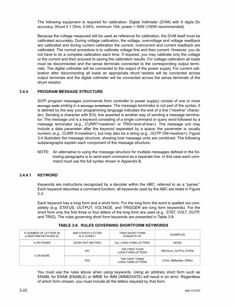
The following equipment is required for calibration: Digital Voltmeter (DVM) with 6 digits Dcaccuracy. Shunt 0.1 Ohm, 0.04%, minimum 15A, power > 50W (100W recommended)
Because the voltage measured will be used as reference for calibration, the DVM itself must becalibrated accurately. During voltage calibration, the voltage, overvoltage and voltage readbackare calibrated and during current calibration the current, overcurrent and current readback arecalibrated. The normal procedure is to calibrate voltage first and then current. However, you donot have to do a complete calibration each time. If required, you may calibrate only the voltageor the current and then proceed to saving the calibration results. For voltage calibration all loadsmust be disconnected and the sense terminals connected to the corresponding output termi-nals. The digital voltmeter will be connected to the output of the power supply. For current cali-bration after disconnecting all loads an appropriate shunt resistor will be connected acrossoutput terminals and the digital voltmeter will be connected across the sense terminals of theshunt resistor.
3.4.4 PROGRAM MESSAGE STRUCTURE
SCPI program messages (commands from controller to power supply) consist of one or moremessage units ending in a message terminator. The message terminator is not part of the syntax; itis defined by the way your programming language indicates the end of a line (“newline” charac-ter). Sending a character with EOL line asserted is another way of sending a message termina-tor. The message unit is a keyword consisting of a single command or query word followed by amessage terminator (e.g., CURR?<newline> or TRIG<end-of-line>). The message unit mayinclude a data parameter after the keyword separated by a space; the parameter is usuallynumeric (e.g., CURR 5<newline>), but may also be a string (e.g., OUTP ON<newline>). Figure3-4 illustrates the message structure, showing how message units are combined. The followingsubparagraphs explain each component of the message structure.
NOTE: An alternative to using the message structure for multiple messages defined in the fol-lowing paragraphs is to send each command as a separate line. In this case each com-mand must use the full syntax shown in Appendix B.
3.4.4.1 KEYWORD
Keywords are instructions recognized by a decoder within the ABC, referred to as a “parser.”Each keyword describes a command function; all keywords used by the ABC are listed in Figure3-3.
Each keyword has a long form and a short form. For the long form the word is spelled out com-pletely (e.g. STATUS, OUTPUT, VOLTAGE, and TRIGGER are long form keywords). For theshort form only the first three or four letters of the long form are used (e.g., STAT, VOLT, OUTP,and TRIG). The rules governing short form keywords are presented in Table 3-8.
You must use the rules above when using keywords. Using an arbitrary short form such asENABL for ENAB (ENABLE) or IMME for IMM (IMMEDIATE) will result in an error. Regardlessof which form chosen, you must include all the letters required by that form.
TABLE 3-8. RULES GOVERNING SHORTFORM KEYWORDS
IF NUMBER OF LETTERS IN LONGFORM KEYWORD IS:
AND FOURTH LETTERIS A VOWEL?
THEN SHORT FORM CONSISTS OF: EXAMPLES
4 OR FEWER (DOES NOT MATTER) ALL LONG FORM LETTERS MODE
5 OR MORE
NO THE FIRST FOURLONG FORM LETTERS MEASure, OUTPut, EVENt
YES THE FIRST THREELONG FORM LETTERS LEVel, IMMediate, ERRor
3-22 ABC 012703
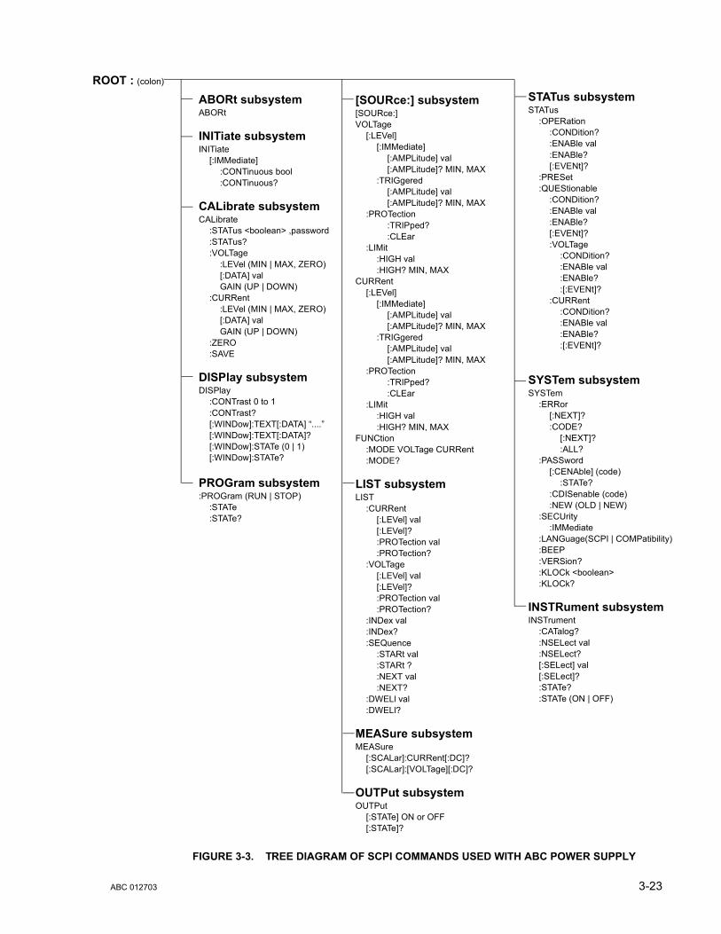
R
FIGURE 3-3. TREE DIAGRAM OF SCPI COMMANDS USED WITH ABC POWER SUPPLY
ABORt subsystemABORt
INITiate subsystemINITiate
[:IMMediate]:CONTinuous bool:CONTinuous?
CALibrate subsystemCALibrate
:STATus <boolean> ,password:STATus?:VOLTage
:LEVel (MIN | MAX, ZERO)[:DATA] valGAIN (UP | DOWN)
:CURRent:LEVel (MIN | MAX, ZERO)[:DATA] valGAIN (UP | DOWN)
:ZERO:SAVE
DISPlay subsystemDISPlay
:CONTrast 0 to 1:CONTrast?[:WINDow]:TEXT[:DATA] “....”[:WINDow]:TEXT[:DATA]?[:WINDow]:STATe (0 | 1)[:WINDow]:STATe?
PROGram subsystem:PROGram (RUN | STOP)
:STATe:STATe?
OOT : (colon)
STATus subsystemSTATus
:OPERation:CONDition?:ENABle val:ENABle?[:EVENt]?
:PRESet:QUEStionable
:CONDition?:ENABle val:ENABle?[:EVENt]?:VOLTage
:CONDition?:ENABle val:ENABle?:[:EVENt]?
:CURRent:CONDition?:ENABle val:ENABle?:[:EVENt]?
SYSTem subsystemSYSTem
:ERRor[:NEXT]?:CODE?
[:NEXT]?:ALL?
:PASSword[:CENAble] (code)
:STATe?:CDISenable (code):NEW (OLD | NEW)
:SECUrity:IMMediate
:LANGuage(SCPI | COMPatibility):BEEP:VERSion?:KLOCk <boolean>:KLOCk?
INSTRument subsystemINSTrument
:CATalog?:NSELect val:NSELect?[:SELect] val[:SELect]?:STATe?:STATe (ON | OFF)
[SOURce:] subsystem[SOURce:]VOLTage
[:LEVel][:IMMediate]
[:AMPLitude] val[:AMPLitude]? MIN, MAX
:TRIGgered[:AMPLitude] val[:AMPLitude]? MIN, MAX
:PROTection:TRIPped?:CLEar
:LIMit:HIGH val:HIGH? MIN, MAX
CURRent[:LEVel]
[:IMMediate][:AMPLitude] val[:AMPLitude]? MIN, MAX
:TRIGgered[:AMPLitude] val[:AMPLitude]? MIN, MAX
:PROTection:TRIPped?:CLEar
:LIMit:HIGH val:HIGH? MIN, MAX
FUNCtion:MODE VOLTage CURRent:MODE?
LIST subsystemLIST
:CURRent[:LEVel] val[:LEVel]?:PROTection val:PROTection?
:VOLTage[:LEVel] val[:LEVel]?:PROTection val:PROTection?
:INDex val:INDex?:SEQuence
:STARt val:STARt ?:NEXT val:NEXT?
:DWELl val:DWELl?
MEASure subsystemMEASure
[:SCALar]:CURRent[:DC]?[:SCALar]:[VOLTage][:DC]?
OUTPut subsystemOUTPut
[:STATe] ON or OFF[:STATe]?
ABC 012703 3-23

FIGURE 3-4. MESSAGE STRUCTURE
To identify the short form and long form in this manual, keywords are written in upper case let-ters to represent the short form, followed by lower case letters indicating the long form (e.g.,IMMediate, EVENt, and OUTPut). The parser, however, is not sensitive to case (e.g., outp,OutP, OUTPUt, ouTPut, or OUTp are all valid).
3.4.4.2 KEYWORD SEPARATOR
If a command has two or more keywords, adjacent keywords must be separated by a colon (:)which acts as the keyword separator (e.g., CURR:LEV:TRIG). The colon can also act as a rootspecifier (paragraph 3.4.4.7).
3.4.4.3 QUERY INDICATOR
The question mark (?) following a keyword is a query indicator. This changes the command intoa query. If there is more than one keyword in the command, the query indicator follows the lastkeyword. (e.g., VOLT? and MEAS:CURR?).
3.4.4.4 DATA
Some commands require data to accompany the keyword either in the form of a numeric valueor character string. Data always follows the last keyword of a command or query (e.g.,VOLT:LEV:TRIG 14 or SOUR:VOLT? MAX
3.4.4.5 DATA SEPARATOR
Data must be separated from the last keyword by a space (e.g., VOLT:LEV:TRIG 14 orSOUR:VOLT? MAX
CURR:LEV 3.5;:OUTP ON;:CURR?<NL>
MESSAGE TERMINATOR
KEYWORD
QUERY INDICATOR
ROOT SPECIFIER
MESSAGE UNIT SEPARATOR
DATA
KEYWORD
KEYWORD
KEYWORD SEPARATOR
KEYWORD
MESSAGE UNIT SEPARATOR
DATA
MESSAGE UNIT
DATA SEPARATOR
DATA SEPARATOR
ROOT SPECIFIER
3-24 ABC 012703

3.4.4.6 MESSAGE UNIT SEPARATOR
When two or more message units are combined in a program message, they must be separatedby a semicolon (;) (e.g., VOLT 15;MEAS:VOLT? and CURR 12; CURR:TRIG 12.5).
3.4.4.7 ROOT SPECIFIER
The root specifier is a colon (:) that precedes the first keyword of a program message. Thisplaces the parser at the root (top left, Figure 3-3) of the command tree. Note the differencebetween using the colon as a keyword separator and a root specifier in the following examples:
VOLT:LEV:IMM 16 Both colons are keyword separators.
:CURR:LEV:IMM 4 The first colon is the root specifier, the other two are keyword separators.
VOLT:LEV 6;:CURR:LEV 15 The second colon is the root specifier, the first and third are key-word separators
:INIT ON;:TRIG;:MEAS:CURR?;VOLT? The first three colons are root specifiers.
3.4.4.8 MESSAGE TERMINATOR
The message terminator defines the end of a message. One message terminator is permitted:
• new line (<NL>), ASCII 10 (decimal) or 0A (hex)
NOTE: Kepco power supplies require a message terminator at the end of each program mes-sage. The examples shown in this manual assume a message terminator will be addedat the end of each message. Where a message terminator is shown it is representedas <NL> regardless of the actual terminator character.
3.4.5 UNDERSTANDING THE COMMAND STRUCTURE
Understanding the command structure requires an understanding of the subsystem commandtree illustrated in Figure 3-3. The “root” is located at the top left corner of the diagram. Theparser goes to the root if:
• a message terminator is recognized by the parser• a root specifier is recognized by the parser
Optional keywords are enclosed in brackets [ ] for identification; optional keywords can be omit-ted and the power supply will respond as if they were included in the message. The root levelkeyword [SOURce] is an optional keyword. Starting at the root, there are various branches orpaths corresponding to the subsystems. The root keywords for the ABC Power Supply are:ABORt, :CALibrate, :DISPlay, :INITiate, :LIST, :MEASure, :OUTPut, [:SOURce], :STATus,:SYSTem and :TRIGger. Because the [SOURce] keyword is optional, the parser moves the pathto the next level, so that VOLTage, CURRent, and FUNCtion commands are at the root level.
Each time the parser encounters a keyword separator, the parser moves to the next indentedlevel of the tree diagram. As an example, the STATus branch is a root level branch that hasthree sub-branches: OPERation, PRESet, and QUEStionable. The following illustrates howSCPI code is interpreted by the parser:
ABC 012703 3-25

STAT:PRES<NL>The parser returns to the root due to the message terminator.
STAT:OPER?;PRES<NL>The parser moves one level in from STAT. The next command is expected at the level definedby the colon in front of OPER?. Thus you can combine the following message unitsSTAT:OPER? and STAT:PRES;
STAT:OPER:COND?;ENAB 16<NL>After the OPER:COND? message unit, the parser moves in one level from OPER, allowing theabbreviated notation for STAT:OPER:ENAB.
3.4.6 PROGRAM MESSAGE SYNTAX SUMMARY
• Common commands begin with an asterisk (*).
• Queries end with a question mark (?).
• Program messages consist of a root keyword and, in some cases, one or more messageunits separated by a colon (:) followed by a message terminator. Several message unitsof a program message may be separated by a semicolon (;) without repeating the rootkeyword.
• If a program message has more than one message unit, then a colon (:) must precedethe next keyword in order to set the parser back to the root (otherwise the next keywordwill be taken as a subunit of the previous message unit).
e.g., the command meas:volt?;curr? will read output voltage and output currentsince both volt? and curr? are interpreted as subunits of the meas command.
• Several commands may be sent as one message; a line feed terminates the message.Commands sent together are separated by a semicolon (;). The first command in a mes-sage starts at the root, therefor a colon (:) at the beginning is not mandatory.
e.g., the command meas:volt?;:curr? will read output voltage and programmed cur-rent since the colon preceding curr? indicates that curr? is not part of the meas com-mand and starts at the root.
• UPPER case letters in mnemonics are mandatory (short form). Lower case letters mayeither be omitted, or must be specified completely (long form)e.g., INSTrument (long form) has the same effect as INST (short form).
• Commands/queries may be given in upper/lower case (long form)e.g., SoUrCe is allowed.
• Text shown between brackets [ ] is optional.e.g., :[SOUR]VOLT:[LEV] TRIG has the same effect as :VOLT TRIG
3.4.7 SCPI PROGRAM EXAMPLES
Refer to Appendix B, Figures B-1 through B-7 for examples illustrating the use of SCPI com-mands.
Figure 3-5 is an example of a program using SCPI commands to program the ABC Power Sup-ply. The program illustrated is for a configuration using an IBM PC or compatible with a National
3-26 ABC 012703
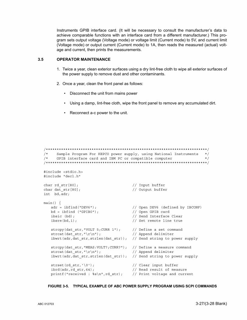
Instruments GPIB interface card. (It will be necessary to consult the manufacturer’s data toachieve comparable functions with an interface card from a different manufacturer.) This pro-gram sets output voltage (Voltage mode) or voltage limit (Current mode) to 5V, and current limit(Voltage mode) or output current (Current mode) to 1A, then reads the measured (actual) volt-age and current, then prints the measurements.
3.5 OPERATOR MAINTENANCE
1. Twice a year, clean exterior surfaces using a dry lint-free cloth to wipe all exterior surfaces ofthe power supply to remove dust and other contaminants.
2. Once a year, clean the front panel as follows:
• Disconnect the unit from mains power
• Using a damp, lint-free cloth, wipe the front panel to remove any accumulated dirt.
• Reconnect a-c power to the unit.
FIGURE 3-5. TYPICAL EXAMPLE OF ABC POWER SUPPLY PROGRAM USING SCPI COMMANDS
/**************************************************************************//* Sample Program For KEPCO power supply, using National Instruments *//* GPIB interface card and IBM PC or compatible computer *//**************************************************************************/
#include <stdio.h>#include "decl.h"
char rd_str[80]; // Input bufferchar dat_str[80]; // Output bufferint bd,adr;
main() {adr = ibfind("DEV6"); // Open DEV6 (defined by IBCONF)bd = ibfind ("GPIB0"); // Open GPIB cardibsic (bd); // Send Interface Clearibsre(bd,1); // Set remote line true
strcpy(dat_str,"VOLT 5;CURR 1"); // Define a set commandstrcat(dat_str,"\r\n"); // Append delimiteribwrt(adr,dat_str,strlen(dat_str)); // Send string to power supply
strcpy(dat_str,"MEAS:VOLT?;CURR?"); // Define a measure commandstrcat(dat_str,"\r\n"); // Append delimiteribwrt(adr,dat_str,strlen(dat_str)); // Send string to power supply
strset(rd_str,'\0'); // Clear input bufferibrd(adr,rd_str,64); // Read result of measureprintf("received : %s\n",rd_str); // Print voltage and current
ABC 012703 3-27/(3-28 Blank)


SECTION 4 - CALIBRATION
4.1 GENERAL
This section contains the calibration instructions for the Power Supply. It is recommended thatthe user be familiar with Local Mode operation (PAR.3.2) before calibrating the unit.
A full calibration consist of a voltage calibration and a current calibration. Both voltage and cur-rent calibrations consist of a zero and a full scale calibration. There are two ways to perform thecalibration: locally using the front panel keys or remotely sending commands through the GPIBbus. These two ways cannot be combined.
In order to enter the calibration mode the correct calibration access code (password) must beentered. If the password has been forgotten, call the factory and a special password (which hasbeen assigned to your power supply) will be provided. During the calibration, new calibrationdata is computed which is then stored in the nonvolatile memory.
4.2 EQUIPMENT REQUIRED
The following equipment is required to calibrate the ABC Power Supply.
• Digital Voltmeter (DVM) with 6 digits d-c accuracy.
• Shunt Resistor: During the calibration procedure the LCD displays the minimum require-ments for the shunt resistor. However, to avoid problems due to drift caused by heat dis-sipation at higher power levels, Kepco recommends the following:
– ABC 10-10DM: 0.1 Ohm, 0.04%, 15A, 50W minimum (100W recommended)
– ABC 15-7DM: 0.1 Ohm, 0.04%, 15A, 50W minimum (100W recommended)
– ABC 25-4DM: 0.25 Ohm, 0.04%, 15A, 50W minimum (100W recommended)
– ABC 36-3DM: 0.25 Ohm, 0.04%, 15A, 50W minimum (100W recommended)
– ABC 60-2DM: 1.0 Ohm, 0.04%, 15A, 50W minimum (100W recommended)
– ABC 125-1DM: 1.0 Ohm, 0.04%, 15A, 50W minimum (100W recommended)
NOTE: Because the voltage measured will be used as reference for calibration, the DVM usedmust be accurately calibrated prior to calibrating the ABC power supply.
4.3 CALIBRATION PROCEDURES
During voltage calibration, the voltage, overvoltage and voltage readback are calibrated andduring current calibration the current, overcurrent and current readback are calibrated. The nor-mal procedure is to calibrate voltage first and then current. However, you do not have to do acomplete calibration each time. If required, you may calibrate only the voltage or the current andthen proceed to saving the calibration results. For either voltage or current calibration, BOTHzero AND full scale calibrations must be performed.
For voltage calibration all loads must be disconnected and the sense terminals connected to thecorresponding output terminals. The digital voltmeter will be connected to the output of thepower supply. For current calibration after disconnecting all loads an appropriate shunt resistorwill be connected across output terminals and the digital voltmeter will be connected across thesense terminals of the shunt resistor.
ABC 012703 4-1

NOTES: Keys with dual functions are labeled with both a command and a number. The com-mand label is referred to when the unit is in command entry status; the number isreferred to when the unit is in data entry status.
1. With the power supply in command entry status , press CALIB key. power supply entersCalibration mode, data entry status .
2. Enter password (4 digits) and press ENTER. If password is incorrect, **WRONG PASS-WORD** flashes, then LCD returns to command status. (See PAR. 4.4 to change the pass-word).
3. If password is correct, LCD reads VOLTAGE CALIB. Enter 1 for voltage calibration (seePAR. 4.3.1), enter 0 to proceed to current calibration.
4. LCD reads CURRENT CALIB. Enter 1 for current calibration (see PAR. 4.3.2), enter 0 to exitCalibration mode.
4.3.1 VOLTAGE CALIBRATION
1. With LCD reading VOLTAGE CALIB. Connect Instr., connect DVM to output (+) and (–) terminals of power supply. then press ENTER.
2. With LCD reading Vout ZERO adj., monitor DVM and use or keys to increase ordecrease output voltage as necessary to get DVM reading as close to zero as possible (with-out going to negative value). Press ENTER when complete.
NOTE: During calibration the (increase) or (decrease) keys are used for fine adjust-ments. If necessary, use the 1 (decrease) and 3 (increase) keys for coarse adjustment,then use the or keys.
3. LCD will flash Vout F.S.adj. **WAIT** then Vout F.S. adj < >. Monitor DVM anduse or keys to increase or decrease output voltage as necessary to get DVM readingas close as possible to full scale value (without exceeding full scale value). E.g., for ABC 25-4DM, adjust for DVM reading as close to 25.000V as possible. Press ENTER when com-plete.
4.3.2 CURRENT CALIBRATION
1. LCD reads CONNECT SHUNT <n OHM >zz A (n and zz values are determined by ABCmodel being calibrated.; e.g., for ABC 10-10DM LCD reads <1 OHM, >50 W). Refer to PAR.4.2 for shunt requirements. Press ENTER.
2. LCD reads CONNECT DVM TO SHUNT. Connect Precision Shunt across output (+) and (–)terminals of power supply and connect DVM to sense terminals of shunt. Press ENTERwhen connections are complete.
NOTE: During calibration the (increase) or (decrease) keys are used for fine adjust-ments. If necessary, use the 1 (decrease) and 3 (increase) keys for coarse adjustment,then use the or keys.
3. With LCD reading Iout ZERO adj., monitor DVM and use or keys to increase ordecrease output current as necessary to get DVM reading as close to zero as possible (with-out going to negative value). Press ENTER when complete.
4-2 ABC 012703
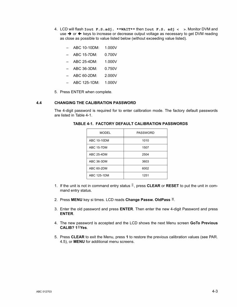
4. LCD will flash Iout F.S.adj. **WAIT** then Iout F.S. adj < >. Monitor DVM anduse or keys to increase or decrease output voltage as necessary to get DVM readingas close as possible to value listed below (without exceeding value listed).
– ABC 10-10DM: 1.000V
– ABC 15-7DM: 0.700V
– ABC 25-4DM: 1.000V
– ABC 36-3DM: 0.750V
– ABC 60-2DM: 2.000V
– ABC 125-1DM: 1.000V
5. Press ENTER when complete.
4.4 CHANGING THE CALIBRATION PASSWORD
The 4-digit password is required for to enter calibration mode. The factory default passwordsare listed in Table 4-1.
1. If the unit is not in command entry status , press CLEAR or RESET to put the unit in com-mand entry status.
2. Press MENU key si times. LCD reads Change Passw. OldPass .
3. Enter the old password and press ENTER. Then enter the new 4-digit Password and pressENTER.
4. The new password is accepted and the LCD shows the next Menu screen GoTo PreviousCALIB? 1 Yes.
5. Press CLEAR to exit the Menu, press 1 to restore the previous calibration values (see PAR.4.5), or MENU for additional menu screens.
TABLE 4-1. FACTORY DEFAULT CALIBRATION PASSWORDS
MODEL PASSWORD
ABC 10-10DM 1010
ABC 15-7DM 1507
ABC 25-4DM 2504
ABC 36-3DM 3603
ABC 60-2DM 6002
ABC 125-1DM 1251
ABC 012703 4-3
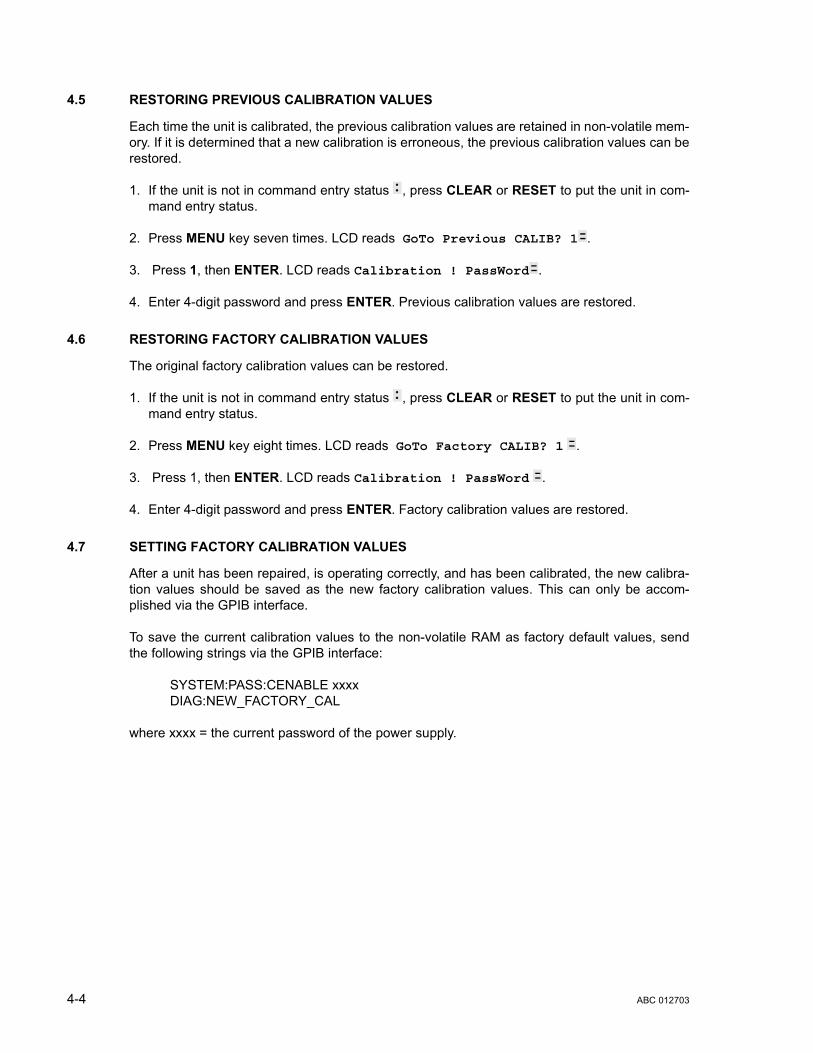
4.5 RESTORING PREVIOUS CALIBRATION VALUES
Each time the unit is calibrated, the previous calibration values are retained in non-volatile mem-ory. If it is determined that a new calibration is erroneous, the previous calibration values can berestored.
1. If the unit is not in command entry status , press CLEAR or RESET to put the unit in com-mand entry status.
2. Press MENU key seven times. LCD reads GoTo Previous CALIB? 1 .
3. Press 1, then ENTER. LCD reads Calibration ! PassWord .
4. Enter 4-digit password and press ENTER. Previous calibration values are restored.
4.6 RESTORING FACTORY CALIBRATION VALUES
The original factory calibration values can be restored.
1. If the unit is not in command entry status , press CLEAR or RESET to put the unit in com-mand entry status.
2. Press MENU key eight times. LCD reads GoTo Factory CALIB? 1 .
3. Press 1, then ENTER. LCD reads Calibration ! PassWord .
4. Enter 4-digit password and press ENTER. Factory calibration values are restored.
4.7 SETTING FACTORY CALIBRATION VALUES
After a unit has been repaired, is operating correctly, and has been calibrated, the new calibra-tion values should be saved as the new factory calibration values. This can only be accom-plished via the GPIB interface.
To save the current calibration values to the non-volatile RAM as factory default values, sendthe following strings via the GPIB interface:
SYSTEM:PASS:CENABLE xxxxDIAG:NEW_FACTORY_CAL
where xxxx = the current password of the power supply.
4-4 ABC 012703

APPENDIX A - IEEE 488.2 COMMAND/QUERY DEFINITIONS
A.1 INTRODUCTION
This appendix defines the IEEE 488.2 commands and queries used with the ABC Power SupplyThese commands and queries are preceded by an asterisk (*) and are defined and explained in Fig-ures A-1 through A-14, arranged in alphabetical order. Table A-1 provides a quick reference of allIEEE 488.2 commands and queries supported in the ABC Power Supply.
A.2 *CLS — CLEAR STATUS COMMAND *CLSSyntax: *CLS
Description: Clears status data. Clears the error queue of the instrument. It also clears the following registerswithout affecting the corresponding Enable Registers: Standard Event Status Register (ESR), Opera-tion Status Event Register, Questionable Status Event Register, and Status Byte Register (STB).Related commands: *OPC *OPC?. (See example, Figure A-1.)
A.3 *ESE — STANDARD EVENT STATUS ENABLE COMMAND *ESESyntax: *ESE <integer> where <integer> = positive whole number: 0 to 255 per Table A-2.
Default Value: 0
Description: This command programs the standard Event Status Enable register bits. The contents functionas a mask to determine which events of the Event Status Register (ESR) are allowed to set the ESB(Event Summary Bit) of the Status Byte Register. Enables the Standard events to be summarized inthe Status Byte register (1 = set = enable function, 0 = reset = disable function). All of the enabledevents of the standard Event Status Enable register are logically ORed to cause ESB (bit 5) of the Sta-tus Byte Register to be set (1 = set = enable, 0 = reset = disable). (See example, Figure A-1.)
TABLE A-1. IEEE 488.2 COMMAND/QUERY INDEXCOMMAND PAR. COMMAND PAR.
*CLS A.2 *RST A.11
*ESE, ? A.3, A.4 *SAV A.12
*ESR? A.5 *SRE, ? A.13, A.14
*IDN? A.6 *STB? A.15
*OPC, ? A.7, A.8 *TRG A.16
*OPT A.9 *TST? A.17
*RCL A.10
TABLE A-2. STANDARD EVENT STATUS ENABLE REGISTER AND STANDARD EVENT STATUS REGISTER BITS
CONDITION PON NU CME EXE DDE QUE NU OPC
BIT 7 6 5 4 3 2 1 0
VALUE 128 64 32 16 8 4 2 1
PON Power OnNU (Not Used)CME Command ErrorEXE Execution ErrorDDE Device Dependent ErrorQUE Query ErrorOPC Operation Complete
ABC 012703 A-1
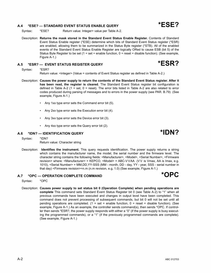
A.4 *ESE? — STANDARD EVENT STATUS ENABLE QUERY *ESE?Syntax: *ESE? Return value: Integer> value per Table A-2.
Description: Returns the mask stored in the Standard Event Status Enable Register. Contents of StandardEvent Status Enable register (*ESE) determine which bits of Standard Event Status register (*ESR)are enabled, allowing them to be summarized in the Status Byte register (*STB). All of the enabledevents of the Standard Event Status Enable Register are logically ORed to cause ESB (bit 5) of theStatus Byte Register to be set (1 = set = enable function, 0 = reset = disable function). (See example,Figure A-1.)
A.5 *ESR? — EVENT STATUS REGISTER QUERY *ESR?Syntax: *ESR?
Return value: <integer> (Value = contents of Event Status register as defined in Table A-2.)
Description: Causes the power supply to return the contents of the Standard Event Status register. After ithas been read, the register is cleared. The Standard Event Status register bit configuration isdefined in Table A-2 (1 = set, 0 = reset). The error bits listed in Table A-2 are also related to errorcodes produced during parsing of messages and to errors in the power supply (see PAR. B.79) (Seeexample, Figure A-1.)
• Any 1xx type error sets the Command error bit (5).
• Any 2xx type error sets the Execution error bit (4).
• Any 3xx type error sets the Device error bit (3).
• Any 4xx type error sets the Query error bit (2).
A.6 *IDN? — IDENTIFICATION QUERY *IDN?Syntax: *IDN?
Return value: Character string
Description: Identifies the instrument. This query requests identification. The power supply returns a stringwhich contains the manufacturer name, the model, the serial number and the firmware level. Thecharacter string contains the following fields: <Manufacturer>, <Model>, <Serial Number>, <Firmwarerevision> where: <Manufacturer> = KEPCO, <Model> = ABC-V VAA (V V is Vmax, AA is Imax, e.g.1010), <Serial Number> = MM,DD,YY-SSS (MM - month, DD - day, YY - year, SSS - serial number inthat day) <Firmware revision>=n.m (n.m revision, e.g, 1.0) (See example, Figure A-1.)
A.7 *OPC — OPERATION COMPLETE COMMAND *OPCSyntax: *OPC
Description: Causes power supply to set status bit 0 (Operation Complete) when pending operations arecomplete This command sets Standard Event Status Register bit 0 (see Table A-2) to “1” when allprevious commands have been executed and changes in output level have been completed. Thiscommand does not prevent processing of subsequent commands, but bit 0 will not be set until allpending operations are completed. (1 = set = enable function, 0 = reset = disable function). (Seeexample, Figure A-1.) As an example, the controller sends command(s), then sends *OPC. If control-ler then sends *ESR?, the power supply responds with either a “0” (if the power supply is busy execut-ing the programmed commands), or a “1” (if the previously programmed commands are complete).(See example, Figure A-1.)
A-2 ABC 012703

A.8 *OPC? — OPERATION COMPLETE QUERY *OPC?Syntax: *OPC?
Return value: <1> (ASCII) placed in output queue when power supply has completed operation.
Description: Indicates when pending operations have been completed.When all pending operations are com-plete (all previous commands have been executed and changes in output level have been completed)a “1” is placed in the Output Queue. Subsequent commands are inhibited until the pending operationsare completed. *OPC? is intended to be used at the end of a command line so that the application pro-gram can monitor the bus for data until it receives the “1” from the power supply Output Queue. (Seeexample, Figure A-1.)
A.9 *OPT? — OPTIONS QUERY *OPT?Syntax: *OPT?
Returns string determined by power supply model.
Description: Causes the power supply to return an ASCII string which defines the functionality of the power supply.The functionality is defined as follows:
A.10 *RCL — RECALL COMMAND *RCLSyntax: *RCL <integer> (1 to 40)
Description: Restores power supply to previously defined levels of output voltage, output current, overvolt-age protection, and overcurrent protection.This command selects one of the 40 power supplymemory locations, each of which stores values for output current, output voltage, overvoltage protec-tion, and overcurrent protection. The following parameters are affected by *RCL: CURR[:LEV][:IMM]VOLT[:LEV][:IMM] CURR:PROT[:LEV] VOLT:PROT[:LEV]. The recall function also sets the unitto operating parameters to SCPI compatible mode, or device clear operation and output on or off. Ifthe recall value was not initialized by the *SAV command, but from an edit save or front panel save,the output condition will remain unchanged along with the language preferences. (See example, Fig-ure A-1.)
STRING DATA MEANING
CAL Support for CALibrate is present.
RL3 Hardware switch controlling remote/local is functional. Unit can be used to take measurements in local mode, but all other functions requeire the unit to be in remote mode (REN must be asserted).
M40 Indicates the number of memory steps supported.
D16 Indicates the number of characters supported for user messages on LCD.
ABC 012703 A-3

FIGURE A-1. GPIB COMMANDS
A.11 *RST — RESET COMMAND *RSTSyntax: *RST
Description: Resets power supply to the power on default state. The power supply is programmed to the poweron values of the following parameters: CURR[:LEV][:IMM] = 0, VOLT[:LEV][:IMM] = 0,CURR:PROT[:LEV] = max overcurrent value (see Table 1-2, VOLT:PROT[:LEV] = (maximum overvolt-age value (see Table 1-2), OUTP[:STAT] = OFF. If the power supply is in either an overvoltage or over-current state, this condition is reset by *RST. (See example, Figure A-1.)
*CLS Power supply clears status data.*ESE 60 Power supply enables bits 5, 4, 3 and 2, allowing command error, execution
error, device dependent error and query error to set the Event Status Summary bit when an STB command is executed.
*ESE? Returns 60, (value of the mask) verifying that bits 5, 4, 3 and 2 are enabled.*ES Unknown command will set command error (Bit 5).*ESR? Returns 32 (bit 5 set), indicating Command Error has occurred since the last
time the register was read.*IDN? Power supply returns: KEPCO, ABC-1010, 082495-001, 1.0.LIST:IND 21 Selects memory location 21.LIST:CURR 2.35E-1 Sets output current value of memory location 21 to 0.235A.LIST:VOLT 14 Sets output voltage value of memory location 21 to 14V.*OPC Allows status bit 0 to be set when pending operations completeVOLT 21;CURR 3 Sets output voltage to 21V, output current to 3A*SAV 33 The present state of the power supply is stored in memory location 33.*ESR? Returns 129 (128 + 1, power on, bit 7 = 1, operation complete, bit 1 = 1)*ESR? Returns 0 (event status register cleared by prior *ESR?)VOLT 15;CURR 5;*OPC? Sets output voltage to 15V, output current to 5A, puts “1” on output bus when
command operations are complete.*RCL 21 Values in memory location 21 recalled (21V, 3A).*RST Power supply reset to power on default state.*SRE 40 When ESB or QUES bits are set (Table A-3), the Request for Service bit will
be set.*SRE? Returns the value of the mask (40).*STB? For example, the Power supply responds with 96 (64 + 32) if MSS and the
Event Status Byte (Table A-3) summary bit have been set. The power supply returns 00 if no bits have been set.
VOLT 25 Power supply voltage commanded to 25V.VOLT:TRIG 12 Programs power supply voltage to 12V when *TRG received.INIT Trigger event is initialized.*TRG Power supply reverts to commanded output voltage of 12V.*TST? Power supply executes self test and responds with 0 if test completed
successfully, with 1 if test failed.
A-4 ABC 012703

A.12 * SAV — SAVE COMMAND *SAVSyntax: *SAV <integer> (1 to 40)
Description: Saves the present state of output voltage, output current, overvoltage and overcurrent to thespecified memory location. This command stores the present state of the power supply to one of 40memory locations. The following parameters are stored by *SAV: CURR[:LEV][:IMM],VOLT[:LEV][:IMM], CURR:PROT[:LEV], and VOLT:PROT[:LEV]. The *SAV command also saves thelanguage status and output on/off state. The stored values can be restored by the *RCL command.(See example, Figure A-1.)
A.13 *SRE — SERVICE REQUEST ENABLE COMMAND *SRESyntax: *SRE<integer> where <integer> = value from 0 - 255 per Table A-3, except bit 6 cannot be pro-
grammed.
Description: Sets the condition of the Service Request Enable register. The Service Request Enable registerdetermines which events of the Status Byte Register are summed into the MSS (Master Status Sum-mary) and RQS (Request for Service) bits. RQS is the service request bit that is cleared by a serialpoll, while MSS is not cleared when read. A "1" (1 = set = enable, 0 = reset = disable) in any ServiceRequest Enable register bit position enables the corresponding Status Byte bit to set the RQS andMSS bits. All the enabled Service Request Enable register bits then are logically ORed to cause Bit 6of the Status Byte Register (MSS/RQS) to be set. Related Commands: *SRE?, *STB?. (See exam-ple, Figure A-1.)
A.14 *SRE? — SERVICE REQUEST ENABLE QUERY *SRE?Syntax: *SRE? Response: <integer> = value from 0 - 255 per Table A-3.
Description: Reads the Service Enable Register. Used to determine which events of the Status Byte Register areprogrammed to cause the power supply to generate a service request (1 = set = function enabled, 0 =reset = function disabled). Related Commands: *SRE, *STB? (See example, Figure A-1.)
A.15 *STB? — STATUS BYTE REGISTER QUERY *STB?Syntax: *STB? Response: <integer> value from 0 to 255 per Table A-3.
Description: Reads Status Byte Register without clearing it. This Query reads the Status Byte Register (bit 6 =MSS) without clearing it (1 = set = function enabled, 0 = reset = function disabled). The register iscleared only when subsequent action clears all set bits. MSS is set when the power supply has oneore more reasons for requesting service. (A serial poll also reads the Status Byte Register, except thatbit 6 = RQS, not MSS; ands RQS will be reset.) Related Commands: *SRE, *SRE?. (See example,Figure A-1.)
TABLE A-3. SERVICE REQUEST ENABLE AND STATUS BYTE REGISTER BITS
CONDITION OPER MSSRQS ESB MAV QUES ERR
QUE NU NU
BIT 7 6 5 4 3 2 1 0
VALUE 128 64 32 16 8 4 2 1
OPER Operation Status SummaryMSS Master Status SummaryRQS Request for ServiceESB Event Status Byte summaryMAV Message availableQUES QUEStionable Status SummaryERR QUE 1 or more errors occurred (see
PAR. B.78)NU (Not Used)
ABC 012703 A-5
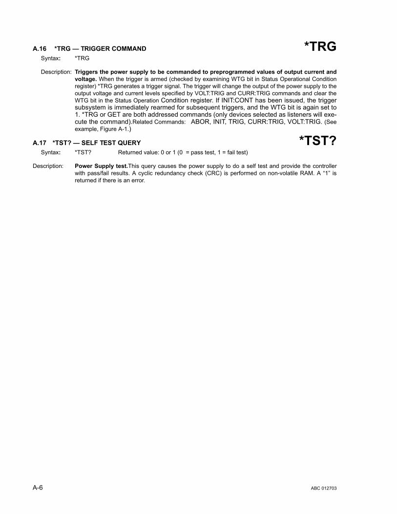
A.16 *TRG — TRIGGER COMMAND *TRGSyntax: *TRG
Description: Triggers the power supply to be commanded to preprogrammed values of output current andvoltage. When the trigger is armed (checked by examining WTG bit in Status Operational Conditionregister) *TRG generates a trigger signal. The trigger will change the output of the power supply to theoutput voltage and current levels specified by VOLT:TRIG and CURR:TRIG commands and clear theWTG bit in the Status Operation Condition register. If INIT:CONT has been issued, the triggersubsystem is immediately rearmed for subsequent triggers, and the WTG bit is again set to1. *TRG or GET are both addressed commands (only devices selected as listeners will exe-cute the command).Related Commands: ABOR, INIT, TRIG, CURR:TRIG, VOLT:TRIG. (Seeexample, Figure A-1.)
A.17 *TST? — SELF TEST QUERY *TST?Syntax: *TST? Returned value: 0 or 1 (0 = pass test, 1 = fail test)
Description: Power Supply test.This query causes the power supply to do a self test and provide the controllerwith pass/fail results. A cyclic redundancy check (CRC) is performed on non-volatile RAM. A “1” isreturned if there is an error.
A-6 ABC 012703
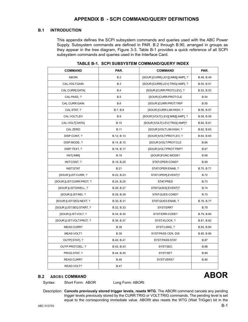
APPENDIX B - SCPI COMMAND/QUERY DEFINITIONS
B.1 INTRODUCTION
This appendix defines the SCPI subsystem commands and queries used with the ABC PowerSupply. Subsystem commands are defined in PAR. B.2 through B.90, arranged in groups asthey appear in the tree diagram, Figure 3-3. Table B-1 provides a quick reference of all SCPIsubsystem commands and queries used in the Interface Card.
B.2 ABORt COMMAND ABORSyntax: Short Form: ABOR Long Form: ABORt
Description: Cancels previously stored trigger levels, resets WTG. The ABORt command cancels any pendingtrigger levels previously stored by the CURR:TRIG or VOLT:TRIG commands. The pending level is setequal to the corresponding immediate value. ABORt also resets the WTG (Wait TriGger) bit in the
TABLE B-1. SCPI SUBSYSTEM COMMAND/QUERY INDEXCOMMAND PAR. COMMAND PAR.
ABORt B.2 [SOUR:]CURR[:LEV][:IMM][:AMP], ? B.48, B.49
CAL:VOLT:GAIN B.3 [SOUR:]CURR[:LEV]:TRIG[:AMP], ? B.50, B.51
CAL:CURR[:DATA] B.4 [SOUR:]CURR:PROT[:LEV], ? B.52, B.53
CAL:PASS, ? B.5 [SOUR:]CURR:PROT:CLE B.54
CAL:CURR:GAIN B.6 [SOUR:]CURR:PROT:TRIP B.55
CAL:STAT, ? B.7, B.8 [SOUR:]CURR:LIM:HIGH, ? B.56, B.57
CAL:VOLT:LEV B.9 [SOUR:]VOLT[:LEV][:IMM][:AMP], ? B.58, B.59
CAL:VOLT[:DATA] B.10 [SOUR:]VOLT[:LEV]:TRIG[:AMP]? B.60, B.61
CAL:ZERO B.11 [SOUR:]VOLT:LIM:HIGH, ? B.62, B.63
DISP:CONT, ? B.12, B.13 [SOUR:]VOLT:PROT:LEV, ? B.64, B.65
DISP:MODE, ? B.14 ,B.15 [SOUR:]VOLT:PROT:CLE B.66
DISP:TEXT, ? B.16, B.17 [SOUR:]VOLT:PROT:TRIP? B.67
INIT[:IMM] B.18 [SOUR:]FUNC:MODE? B.68
INIT:CONT, ? B.19, B.20 STAT:OPER:COND? B.69
INST:STAT B.21 STAT:OPER:ENAB, ? B.70, B.71
[SOUR:]LIST:CURR, ? B.22, B.23 STAT:OPER[:EVENT]? B.72
[SOUR:]LIST:CURR:PROT, ? B.24, B.25 STAT:PRES B.73
[SOUR:]LIST:DWELL, ? B.26, B.27 STAT:QUES[:EVENT]? B.74
[SOUR:]LIST:IND, ? B.28, B.29 STAT:QUES:COND? B.75
[SOUR:]LIST:SEQ:NEXT, ? B.30, B.31 STAT:QUES:ENAB, ? B.76, B.77
[SOUR:]LIST:SEQ:START, ? B.32, B.33 SYST:ERR? B.78
[SOUR:]LIST:VOLT, ? B.34, B.35 SYST:ERR:CODE? B.79, B.80
[SOUR:]LIST:VOLT:PROT, ? B.36, B.37 SYST:KLOCK, ? B.81, B.82
MEAS:CURR? B.38 SYST:LANG, ? B.83, B.84
MEAS:VOLT? B.39 SYST:PASS CEN, DIS B.85, B.86
OUTP[:STAT], ? B.40, B.41 SYST:PASS:STAT B.87
OUTP:PROT:DEL, ? B.42, B.43 SYST:SEC B.88
PROG:STAT, ? B.44, B.45 SYST:SET B.89
READ:CURR? B.46 SYST:VERS? B.90
READ:VOLT? B.47
ABC 012703 B-1
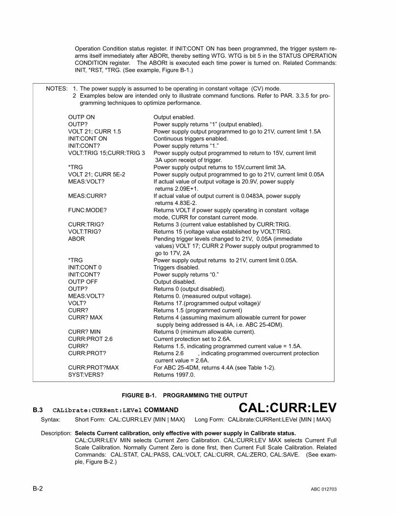
Operation Condition status register. If INIT:CONT ON has been programmed, the trigger system re-arms itself immediately after ABORt, thereby setting WTG. WTG is bit 5 in the STATUS OPERATIONCONDITION register. The ABORt is executed each time power is turned on. Related Commands:INIT, *RST, *TRG. (See example, Figure B-1.)
FIGURE B-1. PROGRAMMING THE OUTPUT
B.3 CALibrate:CURRent:LEVel COMMAND CAL:CURR:LEVSyntax: Short Form: CAL:CURR:LEV {MIN | MAX} Long Form: CALibrate:CURRent:LEVel {MIN | MAX}
Description: Selects Current calibration, only effective with power supply in Calibrate status.CAL:CURR:LEV MIN selects Current Zero Calibration. CAL:CURR:LEV MAX selects Current FullScale Calibration. Normally Current Zero is done first, then Current Full Scale Calibration. RelatedCommands: CAL:STAT, CAL:PASS, CAL:VOLT, CAL:CURR, CAL:ZERO, CAL:SAVE. (See exam-ple, Figure B-2.)
NOTES: 1. The power supply is assumed to be operating in constant voltage (CV) mode.2 Examples below are intended only to illustrate command functions. Refer to PAR. 3.3.5 for pro-
gramming techniques to optimize performance.
OUTP ON Output enabled.OUTP? Power supply returns “1” (output enabled).VOLT 21; CURR 1.5 Power supply output programmed to go to 21V, current limit 1.5AINIT:CONT ON Continuous triggers enabled.INIT:CONT? Power supply returns “1.”VOLT:TRIG 15;CURR:TRIG 3 Power supply output programmed to return to 15V, current limit
3A upon receipt of trigger.*TRG Power supply output returns to 15V,current limit 3A. VOLT 21; CURR 5E-2 Power supply output programmed to go to 21V, current limit 0.05AMEAS:VOLT? If actual value of output voltage is 20.9V, power supply
returns 2.09E+1. MEAS:CURR? If actual value of output current is 0.0483A, power supply
returns 4.83E-2.FUNC:MODE? Returns VOLT if power supply operating in constant voltage
mode, CURR for constant current mode.CURR:TRIG? Returns 3 (current value established by CURR:TRIG.VOLT:TRIG? Returns 15 (voltage value established by VOLT:TRIG.ABOR Pending trigger levels changed to 21V, 0.05A (immediate
values) VOLT 17; CURR 2 Power supply output programmed to go to 17V, 2A
*TRG Power supply output returns to 21V, current limit 0.05A. INIT:CONT 0 Triggers disabled.INIT:CONT? Power supply returns “0.”OUTP OFF Output disabled.OUTP? Returns 0 (output disabled).MEAS:VOLT? Returns 0. (measured output voltage).VOLT? Returns 17.(programmed output voltage)/CURR? Returns 1.5 (programmed current)CURR? MAX Returns 4 (assuming maximum allowable current for power
supply being addressed is 4A, i.e. ABC 25-4DM).CURR? MIN Returns 0 (minimum allowable current).CURR:PROT 2.6 Current protection set to 2.6A.CURR? Returns 1.5, indicating programmed current value = 1.5A.CURR:PROT? Returns 2.6 , indicating programmed overcurrent protection
current value = 2.6A.CURR:PROT?MAX For ABC 25-4DM, returns 4.4A (see Table 1-2).SYST:VERS? Returns 1997.0.
B-2 ABC 012703
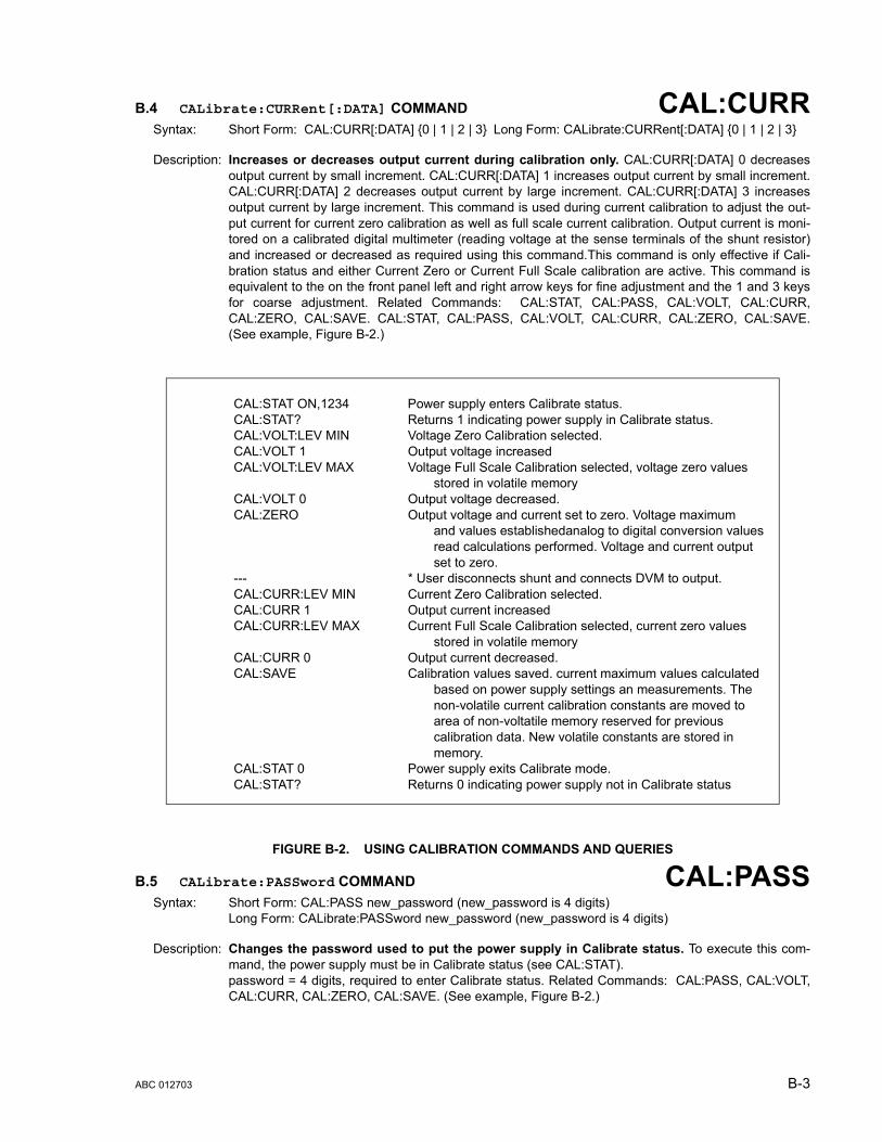
B.4 CALibrate:CURRent[:DATA] COMMAND CAL:CURRSyntax: Short Form: CAL:CURR[:DATA] {0 | 1 | 2 | 3} Long Form: CALibrate:CURRent[:DATA] {0 | 1 | 2 | 3}
Description: Increases or decreases output current during calibration only. CAL:CURR[:DATA] 0 decreasesoutput current by small increment. CAL:CURR[:DATA] 1 increases output current by small increment.CAL:CURR[:DATA] 2 decreases output current by large increment. CAL:CURR[:DATA] 3 increasesoutput current by large increment. This command is used during current calibration to adjust the out-put current for current zero calibration as well as full scale current calibration. Output current is moni-tored on a calibrated digital multimeter (reading voltage at the sense terminals of the shunt resistor)and increased or decreased as required using this command.This command is only effective if Cali-bration status and either Current Zero or Current Full Scale calibration are active. This command isequivalent to the on the front panel left and right arrow keys for fine adjustment and the 1 and 3 keysfor coarse adjustment. Related Commands: CAL:STAT, CAL:PASS, CAL:VOLT, CAL:CURR,CAL:ZERO, CAL:SAVE. CAL:STAT, CAL:PASS, CAL:VOLT, CAL:CURR, CAL:ZERO, CAL:SAVE.(See example, Figure B-2.)
FIGURE B-2. USING CALIBRATION COMMANDS AND QUERIES
B.5 CALibrate:PASSword COMMAND CAL:PASSSyntax: Short Form: CAL:PASS new_password (new_password is 4 digits)
Long Form: CALibrate:PASSword new_password (new_password is 4 digits)
Description: Changes the password used to put the power supply in Calibrate status. To execute this com-mand, the power supply must be in Calibrate status (see CAL:STAT).password = 4 digits, required to enter Calibrate status. Related Commands: CAL:PASS, CAL:VOLT,CAL:CURR, CAL:ZERO, CAL:SAVE. (See example, Figure B-2.)
CAL:STAT ON,1234 Power supply enters Calibrate status.CAL:STAT? Returns 1 indicating power supply in Calibrate status.CAL:VOLT:LEV MIN Voltage Zero Calibration selected.CAL:VOLT 1 Output voltage increasedCAL:VOLT:LEV MAX Voltage Full Scale Calibration selected, voltage zero values
stored in volatile memoryCAL:VOLT 0 Output voltage decreased.CAL:ZERO Output voltage and current set to zero. Voltage maximum
and values establishedanalog to digital conversion values read calculations performed. Voltage and current output set to zero.
--- * User disconnects shunt and connects DVM to output.CAL:CURR:LEV MIN Current Zero Calibration selected.CAL:CURR 1 Output current increasedCAL:CURR:LEV MAX Current Full Scale Calibration selected, current zero values
stored in volatile memoryCAL:CURR 0 Output current decreased.CAL:SAVE Calibration values saved. current maximum values calculated
based on power supply settings an measurements. The non-volatile current calibration constants are moved to area of non-voltatile memory reserved for previous calibration data. New volatile constants are stored in memory.
CAL:STAT 0 Power supply exits Calibrate mode.CAL:STAT? Returns 0 indicating power supply not in Calibrate status
ABC 012703 B-3
B.6 CALibrate:SAVE COMMAND CAL:SAVESyntax: Short Form: CAL:SAVE Long Form: CALibrate:SAVE
Description: Saves computed calibration values in non-volatile memory. The Analog to Digital (A/D) converteris read to establish the final values of the calibration state. For example, if VOLT:MAX was the last cal-ibration state, the voltage A/D converter is read and the volts per step multiplier is calculated. The volt-age per step for the voltage Digital to Analog (D/A) converter is also calculated and the non-voltailememory is updated from the volatile calibration constants. Previous values are not lost, and can berestored using Local mode (see PAR. 4.5 ). This command should be the last command before exitingCalibrate status. CAL:STAT, CAL:PASS, CAL:VOLT, CAL:CURR, CAL:ZERO, CAL:SAVE. (Seeexample, Figure B-2.)
B.7 CALibrate:STATus COMMAND CAL:STATSyntax: Short Form: CAL:STAT <boolean>[,password]
Long Form: CALibrate:STATus <boolean>[,password] where boolean = 0 or OFF, 1 or ON, password = 4 digits, required if<boolean = 1 or ON>
Description: Sets the power supply to Calibrate status. <boolean> 1 or ON causes power supply to enter Cali-brate status. <boolean> 0 or OFF causes power supply to exit Calibrate status. Upon entering Cali-brate status the current calibration constants are stored in the volatile memory. If the state is 0, thenon-volatile calibration constants are supplied to the ASC working calibration.password = 4 digits, required to enter Calibrate status. If the wrong password is entered, error mes-sage -224 is posted to the queue. Related Commands: CAL:PASS, CAL:VOLT, CAL:CURR,CAL:ZERO, CAL:SAVE. (See example, Figure B-2.)
B.8 CALibrate:STATus? QUERY CAL:STAT?Syntax: Short Form: CAL:STAT? Long Form: CALibrate:STATus?
Return Value: <boolean> (boolean = 0 or OFF, 1 or ON)
Description: Identifies whether the power supply is in Calibrate status. 1 indicates power supply is in Calibratestatus. 0 indicates power supply is not in Calibrate status. (See example, Figure B-2.)
B.9 CALibrate:VOLTage:LEVel COMMAND CAL:VOLT:LEVSyntax: Short Form: CAL:VOLT:LEV {MIN | MAX} Long Form: CALibrate:VOLTage:LEVel {MIN | MAX}
Description: Selects Voltage calibration, only effective with power supply in Calibrate status. CAL:VOLT:LEV MIN selects Voltage Zero Calibration. CAL:VOLT:LEV MAX selects Voltage Full ScaleCalibration. Normally Voltage Zero is done first, then Voltage Full Scale Calibration. CAL:VOLT:MAXcauses the maximum value to be read and saved in calibration xx. The power supply then raises theoutput level to maximum and waits for CAL:VOLT[:DATA] commands. Related Commands:CAL:STAT, CAL:PASS, CAL:VOLT, CAL:CURR, CAL:ZERO, CAL:SAVE. (See example, Figure B-2.)
B.10 CALibrate:VOLTage[:DATA] COMMAND CAL:VOLTSyntax: Short Form: CAL:VOLT[:DATA] {0 | 1 | 2 | 3} Long Form: CALibrate:VOLTage[:DATA] {0 | 1 | 2 | 3}
Description: Increases or decreases output voltage during calibration only. CAL:VOLT[:DATA] 0 decreases output voltage by small increment. CAL:VOLT[:DATA] 1 increases out-put voltage by small increment. CAL:VOLT[:DATA] 2 decreases output voltage by large increment.CAL:VOLT[:DATA] 3 increases output voltage by large increment. This command is used during volt-age calibration to adjust the output voltage for voltage zero calibration as well as full scale voltage cal-ibration. Output voltage is monitored on a calibrated digital multimeter and increased or decreased asrequired using this command. This command is only effective if Calibration status and either VoltageZero or Voltage Full Scale calibration are active. This command is equivalent to the front panel left andright arrow keys for fine adjustment and the 1 and 3 keys for coarse adjustment. Related Commands:CAL:STAT, CAL:PASS, CAL:VOLT, CAL:CURR, CAL:ZERO, CAL:SAVE. (See example, Figure B-2.)
B-4 ABC 012703

B.11 CALibrate:ZERO COMMAND CAL:ZEROSyntax: Short Form: CAL:ZERO Long Form: CALibrate:ZERO
Description: Sets output to zero while calibration equipment connections are changed.This command is used whenchanging from Voltage to Current calibration or vice-versa. CAL:ZERO sets output voltage and currentto zero. The user then connects or disconnects the shunt resistor or the digital voltmeter from the out-put terminals of the power supply as required for the subsequent Voltage or Current calibration. Thenext command should select the new parameter to be calibrated. Related Commands: CAL:STAT,CAL:VOLT, CAL:CURR, CAL:SAVE. (See example, Figure B-2.)
B.12 DISPlay:CONTrast COMMAND DISP:CONTSyntax: Short Form: DISP:CONT <num_value> (0 to 1)
Long Form: DISPlay:CONTrast <num_value> (0.0 to 1.0)
Description: Sets the contrast of the front panel LCD. The contrast value from (0.1 to 0.9) is stored in the non-volatile memory and is retained when the power supply is turned off. A contrast value of 0 is best whenlooking up at the display, 1 is best when looking down at the display. Values in between provide adjust-ment for optimum viewing. Setting the values to 0.1 or 0.9 are not reported back and are rounded to 0oe 1 respectively. Related Commands: DISP:CONT?. (See example, Figure B-3.)
FIGURE B-3. USING DISPLAY COMMANDS
B.13 DISPlay:CONTrast? QUERY DISP:CONT?Syntax: Short Form: DISP:CONT? Long Form: DISPlay:CONTrast?
Return Value: Numerical value from 0 to 1 indicating contrast setting.
Description: Identifies LCD contrast setting. Returns 0 if LCD is at minimum setting, 1 if at maximum setting.Cand= return values between 0.2 through 0.8 for other contrast settings. Related Commands:DISP:CONT. (See example, Figure B-3.)
B.14 DISPlay:MODE COMMAND DISP:MODESyntax: Short Form: DISP:MODE NORM or DISP:MODE TEXT
Long Form:: DISPlay:MODE NORMal or DISPlay:MODE TEXT
Description: Switches the LCD display between Normal and Text mode. Switches the display between its nor-mal metering mode and a mode in which it displays text sent by the user on the second line. Thedefault status at power up or after *RST is NORMal. In order to display text on the second line the dis-play mode has to be changed to TEXT. Related Commands: DISP:MODE?, DISP:TEXT,DISP:TEXT?, *RST. (See example, Figure B-3.)
B.15 DISPlay:MODE? QUERY DISP:MODE?Syntax: Short Form: DISP:MODE? Long Form: DISPlay:MODE?
Return Value: NORMAL or TEXT.
Description: Identifies the LCD mode. Returns NORMAL when the display is in normal mode, TEXT when the dis-play is in text mode. Related Commands: DISP:MODE, DISP:TEXT, *RST. (See example, Figure B-3.)
DISP:CONT 0.9 Sets LCD contrast value to 0.9.DISP:CONT? Returns 0.9.DISP:MODE NORM Changes LCD to Normal metering mode.DISP:MODE? Returns NORMAL.DISP:MODE TEXT Changes LCD to Text mode.DISP:TEXT “**ABC IS IN USE” Second line of display reads **ABC IS IN USE.DISP:MODE? Returns “TEXT”DISP:TEXT? Returns “**ABC IS IN USE”
ABC 012703 B-5

B.16 DISPlay:TEXT COMMAND DISP:TEXTSyntax: Short Form: DISP:TEXT[:DATA] <char_string> Long Form: DISPlay:TEXT [:DATA] <char_string>
Description: Allows entry of character string to be viewed when LCD display is set to Text mode. Allows forcharacter strings of maximum 16 characters to be displayed (on the second line of the LCD) when thedisplay mode is TEXT, e.g., DO NOT TOUCH or ABC IS IN USE, etc. The LCD has the following char-acter set: A to Z, 0 to 9 and special characters as < > + - / = : ... If the message exceeds the displaycapacity only the first 16 characters will be displayed and no error message will be generated. Uponexecuting *RST, character string set to 16 spaces:” “. Related Commands: DISP:TEXT?,DISP:MODE, DISP:MODE?, *RST. (See example, Figure B-3.)
B.17 DISPlay:TEXT? QUERY DISP:TEXT?Syntax: Short Form: DISP:TEXT? Long Form: DISPlay:TEXT]?
Return Value: Character string displayed on second line of LCD display.
Description: Returns the text displayed on second line of LCD in TEXT mode. When the display set to TEXTmode, returns the character string entered by DISP:TEXT. If the display set to NORMAL mode, returnsinformation displayed on second line of display. (This can be used to see the monitored values pres-ently being displayed on the second line of the LCD.) Related Commands: DISP:MODE, DISP:TEXT,*RST. (See example, Figure B-3.)
B.18 INITiate[:IMMediate] COMMAND INIT[:IMM]Syntax: Short Form: INIT:[IMM] Long Form: INITiate[:IMMediate]
Description: Enables a single trigger. If INIT:CONT is OFF, then INIT[:IMM] arms the trigger system for a singletrigger. If INIT:CONT is ON, then the trigger system is continuously armed and INIT[:IMM] is redun-dant. This command enables a single trigger. A GPIB <GET>, *TRG or command completes thesequence. Upon receipt of the <GET> or *TRG command, the power supply will return to the pro-grammed values of voltage and current established by the VOLT:TRIG and CURR:TRIG commands.After a GPIB <GET> or *TRG command has been received, subsequent GPIB <GET>, *TRG com-mands have no effect unless preceded by INIT or INIT:CONT ON. Related Commands: <GET>,*RST, *TRG. (See example, Figure B-1.)
B.19 INITiate:CONTinuous COMMAND INIT:CONTSyntax: Short Form: INIT:CONT {ON | OFF} or {1 | 0} ( 1 = on, 0 = off)
Long Form: INITiate:CONTinuous {ON | OFF} or {1 | 0} ( 1 = on, 0 = off)
Description: INIT:CONT ON enables continuous triggers.; INIT:CONT OFF disables continuous triggers. IfINIT:CONT is OFF, then INIT[:IMM] arms the trigger system for a single trigger. If INIT:CONT is ON,then the trigger system is continuously armed and INIT[:IMM] is redundant. Executing *RST commandsets INIT:CONT to OFF. (See example, Figure B-1.)
B.20 INITiate:CONTinuous QUERY INIT:CONT?Syntax: Short Form: INIT:CONT? Long Form: :INITiate:CONTinuous?
Return Value: 1 or 0
Description: Determines whether continuous triggers are enabled or disabled. Power supply returns value ofINIT:CONT flag: “1” = continuous triggers are enabled (INIT:CONT ON); “0” = continuous triggersdisabled (INIT:CONT OFF). (See example, Figure B-1.)
B.21 INSTrument:STATe COMMAND INST:STATSyntax: Short Form :INST:STAT <val> Long Form: INSTrument:STATe <val>
Description: Operation is identical to OUTPut:STATe command (PAR. B.40) and is provided for compatibility withother vendors products.
B-6 ABC 012703

B.22 LIST:CURRent COMMAND LIST:CURRSyntax: Short Form: LIST:CURR[:LEV] <exp_value> Long Form: LIST:CURRent[:LEVel] <exp_value>
<exp_value> = digits with decimal point and Exponent, e.g., 2.71E+1 for 27.1
Description: Sets the current (Amps) value for the memory location selected by LIST:IND. If the value is out ofthe acceptable current range for the power supply model, an error message: -222,"Data out of range"is posted in the output queue. The current value is stored in non-volatile memory and is retained whenthe power supply is turned off. Related Commands: LIST:IND. LIST:IND?, LIST:CURR?. (See exam-ple, Figure B-4.)
B.23 [SOUR:]LIST:CURRent? QUERY LIST:CURR?Syntax: Short Form: LIST:CURR[:LEV]? Long Form: LIST:CURRent[:LEVel]?
Return Value: <exp_value> = digits with decimal point and Exponent, e.g., 2.71E+1 for 27.1
Description: Returns current value (Amps) stored in indexed memory location selected by LIST:IND. RelatedCommands: LIST:IND. LIST:IND?, LIST:CURR. (See example, Figure B-4.)
B.24 [SOUR:]LIST:CURRent:PROTect COMMAND LIST:CURR:PROTSyntax: Short Form: LIST:CURR:PROT<num_value> Long Form: LIST:CURRent:PROTect <num_value>
<num_value> = digits with decimal point and Exponent
Description: Sets the current protection (Amps) value for the memory location selected by LIST:IND. If thevalue is out of the acceptable current range for the power supply model, an error message:-222,"Data out of range" is posted in the output queue. The current value is stored in non-volatilememory and is retained when the power supply is turned off. Related Commands: LIST:IND.LIST:IND?, LIST:CURR:PROT?. (See example, Figure B-4.)
FIGURE B-4. USING LIST COMMANDS AND QUERIES
LIST:IND 21 Selects memory location 21.LIST:IND? Returns 21.LIST:CURR 2.35E-1 Sets output current value of memory location 21 to 0.235A.LIST:CURR? Returns 2.35E-1.LIST:CURR:PROT 1.67E+1 Sets output current value of memory location 21 to 16.7A.LIST:CURR:PROT? Returns 1.67E+1.LIST:VOLT:PROT 2.77E+1 Sets voltage protection value of memory location 21 to 27.7V.LIST:VOLT:PROT? Returns 2.77E+1.LIST:DWEL 0.6 Sets memory location 21 time value to 0.6 second. During program
execution, after parameters specified by memory location 21 have been applied for 0.6 second, power supply will switch to parameters specified by memory location 21 sequence number.
LIST:SEQ:NEXT 39 Sets memory location sequence number to 39. During program execution, when memory location 21 is complete, the next location to be executed will be 39.
LIST:SEQ:NEXT? Returns 39.LIST:IND 22 Selects memory location 22 .LIST:IND? Returns 22.LIST:VOLT 1.256E+2 Sets output voltage value of memory location 22 to 125.6V.LIST:VOLT? Returns 1.256E+2.LIST:SEQ:STAR 21 Sets memory location 21 as the starting location for executing a
program.LIST:SEQ:STAR? Returns 21.PROG:SEL:STAT RUN Sequence starting at location 21 and ending at location 22 will be run
continuouslyPROG:SEL:STAT STOP Programmed sequence stops running.
ABC 012703 B-7
B.25 [SOUR:]LIST:CURRent:PROTect? QUERY LIST:CURR:PROT?Syntax: Short Form: LIST:CURR[:LEV]? Long Form: LIST:CURRent[:LEVel]?
Return Value: <exp_value> = digits with decimal point and Exponent, e.g., 2.71E+1 for 27.1
Description: Returns current protection value (Amps) stored in indexed memory location selected byLIST:IND. Related Commands: LIST:IND. LIST:IND?, LIST:CURR. (See example, Figure B-4.)
B.26 [SOUR:]LIST:DWELl COMMAND LIST:DWELSyntax: Short Form: LIST:DWEL <value> (0.01 to 300) Long Form: LIST:DWELl <value> (0.01 to 300)
Description: Determines the execution time duration during a programmed sequence for the memory loca-tion selected by LIST:IND. Sets time value (from 0.01 to 300) in seconds for memory locationselected by LIST:IND. A value of 0 means that this memory location will be skipped during the RUNcommand (LOCal mode). The time value is stored in non-volatile memory and is retained when thepower supply is turned off. Related Commands: LIST:IND. LIST:IND?, LIST:DWEL?, LIST:SEQ. (Seeexample, Figure B-4.)
B.27 [SOUR:]LIST:DWELl? QUERY LIST:DWEL?Syntax: Short Form: LIST:DWEL? Long Form: LIST:DWELl?
Return Value: <value> (0.01 to 300)
B.28 [SOUR:]LIST:INDex COMMAND LIST:INDSyntax: Short Form: LIST:IND <int_value> (from 1 to 40) Long Form: LIST:INDex <int_value> (from 1 to 40)
Description: Selects one 40 memory locations for viewing or modification of parameter selected by subse-quent LIST:CURR, LIST:CURR:PROT, LIST:VOLT, LIST:VOLT:PROT commands or queries. Theindex value (the selected memory location) is stored in non-volatile memory and is retained when thepower supply is turned off. Related Commands: LIST:IND?. (See example, Figure B-4.)
B.29 [SOUR:]LIST:INDex? QUERY LIST:IND?Syntax: Short Form: LIST:IND? Long Form: LIST:INDex?
Return Value: <int_value> 1 to 40
Description: Returns index value. Identifies which one 40 memory locations has been selected for viewing ormodification by subsequent LIST:CURR, LIST:CURR:PROT, LIST:VOLT, LIST:VOLT:PROT commandsor queries. Related Commands: LIST:IND?. (See example, Figure B-4.)
B.30 [SOUR:]LIST:SEQuence:NEXT COMMAND LIST:SEQ:NEXTSyntax: Short Form: LIST:SEQ:NEXT <int_value> (0 to 40)
Long Form: LIST:SEQuence:NEXT <int_value> (0 to 40)
Description: Determines the next memory location to be addressed during a programmed sequence.Setssequence number (from 1 to 40) of next memory location to be addressed. Sequence number is setfor memory location selected by LIST:IND. Setting sequence number to 0 indicates the end of the pro-gram chain, and the programmed sequence will stop. The sequence number is stored in non-volatilememory and is retained when the power supply is turned off. Related Commands: LIST:IND.LIST:IND?, LIST:SEQ?. (See example, Figure B-4.)
B.31 [SOUR:]LIST:SEQuence:NEXT? QUERY LIST:SEQ:NEXT?Syntax: Short Form: LIST:SEQ:NEXT? Long Form: LIST:SEQuence:NEXT?
Return Value: <int_value> (0 to 40)
Description: Returns sequence number stored in memory location selected by LIST:IND. Related Com-mands: LIST:IND. LIST:IND?, LIST:SEQ. (See example, Figure B-4.)
B-8 ABC 012703
B.32 [SOUR:]LIST:SEQuence:STARt COMMAND LIST:SEQ:STARSyntax: Short Form: LIST:SEQ:STAR <int_value> (1 to 40)
Long Form: LIST:SEQuence:STARt <int_value> (1 to 40)
Description: Determines the first memory location (start of sequence) to be addressed during a pro-grammed sequence. Sets memory location (from 1 to 40) of first memory location to be addressedwhen a program (chain of memory locations) is executed. This is the start address for the STEP andRUN commands (LOCal mode). The starting sequence number is stored in non-volatile memory andis retained when the power supply is turned off. Related Commands: LIST:SEQ:STAR?. (See exam-ple, Figure B-4.)
B.33 [SOUR:]LIST:SEQuence:STARt? QUERY LIST:SEQ:STAR?Syntax: Short Form: LIST:SEQ:STAR? Long Form: LIST:SEQuence:STARt?
Return Value: <int_value) between 1 and 40
Description: Identifies the starting address for program execution. Returns the starting sequence location setby LIST:SEQ:STAR command. Related Commands: LIST:SEQ:STAR. (See example, Figure B-4.)
B.34 [SOUR:]LIST:VOLTage COMMAND LIST:VOLTSyntax: Short Form: LIST:VOLT[:LEV] <exp_value> Long Form: LIST:VOLTage[:LEVel] <exp_value>
<exp_value> = digits with decimal point and Exponent, e.g., 2.71E+1 for 27.1
Description: Sets the voltage value for the memory location selected by LIST:IND. If the value is out of theacceptable voltage range for the power supply model, an error message: -222,"Data out of range" isposted in the output queue. The voltage value is stored in non-volatile memory and is retained whenthe power supply is turned off. Related Commands: LIST:IND. LIST:IND?, LIST:VOLT? (See example,Figure B-4.)
B.35 [SOUR:]LIST:VOLTage? QUERY LIST:VOLT?Syntax: Short Form: LIST:VOLT[:LEV]? Long Form: LIST:VOLTage[:LEVel]?
Return Value: <exp_value> = digits with decimal point and Exponent, e.g., 2.71E+1 for 27.1
Description: Returns voltage value stored in indexed memory location selected by LIST:IND. Related Com-mands: LIST:IND. LIST:IND?, LIST:VOLT. (See example, Figure B-4.)
B.36 [SOUR:]LIST:VOLTage:PROTect COMMAND LIST:VOLT:PROTSyntax: Short Form: LIST:VOLT:PROT<exp_value> Long Form: LIST:VOLTage:PROTect <exp_value>
<exp_value> = digits with decimal point and Exponent, e.g., 2.71E+1 for 27.1
Description: Sets the voltage protection value for the indexed memory location selected by LIST:IND.If thevalue is out of the acceptable voltage range for the power supply model, an error message:-222,"Data out of range" is posted in the output queue. The voltage value is stored in non-volatilememory and is retained when the power supply is turned off. Related Commands: LIST:IND.LIST:IND?, LIST:VOLT:PROT?. (See example, Figure B-4.)
B.37 [SOUR:]LIST:VOLTage:PROTect QUERY LIST:VOLT:PROT?Syntax: Short Form: LIST:VOLT[:LEV]? Long Form: LIST:VOLTage[:LEVel]?
Return Value: <num_value> (digits with decimal point and Exponent)
Description: Returns voltage protection value stored in indexed memory location selected by LIST:IND.Related Commands: LIST:IND. LIST:IND?, LIST:VOLT. (See example, Figure B-4.)
ABC 012703 B-9

B.38 MEASure[:SCALar]:CURRent[:DC]? QUERY MEAS:CURR?Syntax: Short Form: MEAS[:SCAL]:CURR[:DC]? Long Form: MEASure[:SCALar]:CURRent[:DC]?
Return Value: <num_value> (digits with decimal point and Exponent)
Description: Measures actual current. This query returns the actual value of output current (measured at the out-put terminals) as determined by the programmed value of voltage and current and load conditions.NOTE: The SCPI convention for this command allows the controller to establish the range and accu-racy of the measurement if nn,nn is added after the question mark; the power supply accepts this for-mat but sets the command warning bit (13) in the status questionable register and ignores the extracharacters. (See example, Figure B-1.)
B.39 MEASure[:VOLTage][:SCALar][:DC]? QUERY MEAS:VOLT?Syntax: Short Form: MEAS[:SCAL]:VOLT[:DC]? Long Form: MEASure[:SCALar]:VOLTage[:DC]?
Description: Measures actual voltage. This query returns the actual value of output voltage (measured at the out-put terminals) as determined by the programmed value of voltage and current and load conditions.NOTE: The SCPI convention for this command allows the controller to establish the range and accu-racy of the measurement if nn,nn is added after the question mark; the power supply accepts this for-mat but sets the command warning bit (13) in the status questionable register and ignores the extracharacters. (See example, Figure B-1.)
B.40 OUTPut[:STATe] COMMAND OUTPSyntax: Short Form: OUTP[:STAT] <boolean> Long Form: OUTPut[:STATe] <boolean>
<boolean>=(0 or OFF, 1 or ON)
Description: Enables or disables the power supply output. Upon power up the output is enabled (OUTP ON).When OUTP OFF is executed, the programmed values of voltage and current are saved, then voltageand current are programmed to 0. When OUTP ON is executed, the power supply output is restored tothe previously saved programmed values. The saved values of voltage and current can be viewed byVOLT? and CURR? queries. Related Commands: OUTP?. (See example, Figure B-1.)
B.41 OUTPut[:STATe] QUERY OUTP?Syntax: Short Form: OUTP[:STAT]? Long Form: OUTPut[:STATe]?
Return Value: <int_value> (0 or 1)
Description: Indicates whether power supply output is enabled or disabled. Returns 0 if output disabled,returns 1 if output enabled. Related Commands: OUTP. (See example, Figure B-1.)
B.42 OUTPut:PROTection:DELay COMMAND OUTP:PROT:DELSyntax: Short Form: OUTP:PROT:DEL <n.n> Long Form: OUTPut:PROTection:DELay <n.n>
where n.n = seconds
Description: Delays tripping of overvoltage/overcurrent protection. The overvoltage and overcurrent protectioncan be programmed to trip immediately upon detection of an overvoltage/overcurrent condition, or canbe delayed approximately 8 seconds. This delay is set in increments of 0.033 milliseconds If delay isprogrammed, overcurrent/overvoltage protection trips only if condition still present at end of delay. Acount of 0 means no delay, the maximum delay possible is 8.50 seconds.
B.43 OUTPut:PROTection:DELay QUERY OUTP:PROT:DEL?Syntax: Short Form: OUTP:PROT:DEL? Long Form: OUTPut:PROTection:DELay?
Return Value: <integer 1 to 8.5>
Description: Returns value of overvoltage/overcurrent delay. A count of 0 means no delay, The maximumvalue is 8.5. The delay constants are set in -.033 milliseconds per internal value. Related Commands:OUTP:PROT:DEL. (See example, Figure B-5.)
B-10 ABC 012703

B.44 PROGram:SELect:STATe COMMAND PROG:SEL:STATSyntax: Short Form: PROG:SEL:STAT {RUN | STOP}
Long Form: PROGram:SELect:STATe {RUN | STOP}
Description: Starts or stops user programmed sequence. Program sequence is preprogrammed using LISTcommands, starting address is is established by LIST:SEQ:STAR. When PROG:SEL:STAT commandis executed the keyboard is locked until the program stops running. *RST command aborts a programthat is running. Related commands: PROG:SEL:STAT?, LIST:CURR, LIST:CURR:PROT, LIST:VOLT,LIST:VOLT:PROT, LIST:DWEL, LIST:SEQ:NEXT, LIST:SEQ:STAR
B.45 PROGram:SELect:STATe? QUERY PROG:SEL:STAT?Syntax: Short Form: PROG:SEL:STAT? Long Form: PROGram:SELect:STATe?
Return value: <boolean> (0 = stopped, 1 = running)
Description: Indicates status of user progammed sequence. 1 returned when program is running. 0 returnedwhen program is stopped. Related commands: PROG:STAT
B.46 READ[:SCALar]:CURRent[:DC]? QUERY READ:CURR?Syntax: Short Form: READ[:SCAL]:CURR[:DC]? Long Form: READ[:SCALar]:CURRent[:DC]?
Return Value: <num_value> (digits with decimal point and Exponent)
Description: Measures actual current. Same as MEAS:CURR? (see PAR. B.38)
B.47 READ[:VOLTage][:SCALar][:DC]? QUERY READ:VOLT?Syntax: Short Form: READ[:SCAL]:VOLT[:DC]? Long Form: READ[:SCALar]:VOLTage[:DC]?
Description: Measures actual voltage. Same as MEAS:VOLT? (see PAR. B.39)
B.48 [SOURce:]CURRent[:LEVel][:IMMediate][:AMPlitude] COMMAND CURRSyntax: Short Form: [SOUR:]CURR[:LEV][:IMM][:AMP] <exp_value>
Long Form: [SOURce:]CURRent[:LEVel][:IMMediate][:AMPlitude] <exp_value><exp_value> = digits with decimal point and Exponent, e.g., 2.71E+1 for 27.1
Description: Sets programmed current level at power supply output. This command programs output current toa specific value; actual output current will depend on load conditions. If the value exceeds the maxi-mum for the model being programmed, error message -222,”Data out of range” is posted in outputqueue. If value programmed exceeds the CURR:LIM:HIGH value, a value corresponding to the cur-rent limit will be programmed. Related Commands: *RCL, *SAV, CURR:LIM:HIGH. (See example,Figure B-1.)
B.49 [SOURce:]CURRent[:LEVel][:IMMediate][:AMPlitude] QUERY CURR?Syntax: Short Form: [SOUR:]CURR[:LEV][:IMM][:AMP]? MIN, MAX
Long Form: [SOURce:]CURRent[:LEVel][:IMMediate][:AMPlitude]? MIN, MAXReturn Value:<exp_value> = digits with decimal point and Exponent, e.g., 2.71E+1 for 27.1
Description: Returns either the programmed value, maximum value, or minimum value of current. TheCURR? query returns the programmed value of current. Actual output current will depend on load con-ditions. The CURR?MAX query returns the maximum current allowed for a particular model. CURR?Returns programmed current value. CURR? MAX returns maximum current allowed for power supply.CURR? MIN returns minimum current allowed for power supply (always 0). Related Commands:CURR. (See example, Figure B-1.)
B.50 [SOURce:]CURRent:[:LEVel]TRIGgered[:AMPlitude] COMMAND CURR:TRIGSyntax: Short Form: [SOUR:]CURR[:LEV]:TRIG[:AMP] <exp_value>
Long Form: [SOURce:]CURRent[:LEVel]:TRIGgered[:AMPlitude] <exp_value><exp_value> = digits with decimal point and Exponent, e.g., 2.71E+1 for 27.1
Description: Programs current value to be transferred to output by *TRG commands. Actual output currentwill depend on load conditions. If the value exceeds the maximum for the model being programmed,
ABC 012703 B-11

error message -222,”Data out of range” is posted in output queue. If value exceeds CURR:LIM:HIGHvalue, a value corresponding to the current limit will be programmed. Related Commands: CURR.(See example, Figure B-1.)
B.51 [SOURce:]CURRent:[:LEVel]TRIGgered[:AMPlitude]? QUERY CURR:TRIG?Syntax: Short Form: [SOUR:]CURR[:LEV]:TRIG[:AMP]?
Long Form: [SOURce:]CURRent[:LEVel]:TRIGgered[:AMPlitude]?Return Value: <exp_value> = digits with decimal point and Exponent, e.g., 2.71E+1 for 27.1
Description: Returns the current value established by CURR:TRIG command. (See example, Figure B-1.)
B.52 [SOURce:]CURRent:PROTection[:LEVel] COMMAND CURR:PROTSyntax: Short Form: [SOUR:]CURR:PROT[:LEV] <exp_value>
Long Form: [SOURce:]CURRent:PROTection[:LEVel] <exp_value><exp_value> = digits with decimal point and Exponent, e.g., 2.71E+1 for 27.1
Description: Sets overcurrent protection level for power supply. If the value is out of the acceptable overcurrentrange for the power supply model, error message -222,"Data out of range" is posted in the outputqueue. If the power supply output exceeds the current protection level programmed, then the powersupply output is disabled (programmed to 0) and the OV bit in the Questionable Condition status reg-ister is set. An overcurrent condition can be cleared with the CURR:PROT:CLE command. The currentprotection level can be programmed independently of the output current level. Setting current protec-tion to a value lower than the output current causes the current protection mechanism to trigger afterthe delay established by OUTP:PROT:DEL command. (See example, Figure B-5.)
FIGURE B-5. PROGRAMMING CURRENT
NOTES: 1. The power supply is assumed to be operating in constant voltage (CV) mode.2 Examples below are intended only to illustrate command functions. Refer to PAR. 3.3.5 for
programming techniques to optimize performance
VOLT 21; CURR 1.1 Power supply programmed to voltage limit 21V, 1.1A.CURR? Returns 1.1.CURR:LIM:HIGH 3.3 Current limit set to 3.3A.CURR:LIM:HIGH? Returns 3.3.CURR 4.2 Power supply output current programmed to 3.3A, error message
-301 posted.CURR? Returns 3.3.OUTP:PROT:DEL 0 Protection will trip immediately upon detection of overvoltage or
overcurrent condition.OUTP:PROT:DEL? Returns 0.CURR:PROT:TRIP? 0 indicating overcurrent protection not tripped. --- OVERCURRENT CONDITION (1 SECOND) OCCURS.CURR:PROT:TRIP? 1 indicating overcurrent protection tripped.CURR:PROT:CLE Overcurrent condition cleared.CURR:PROT:TRIP? 0 indicating overcurrent condition not tripped.CURR? Returns small value (approx. 1% of full scale current rating).OUTP:PROT:DEL 7.47 Protection will trip if overvoltage or overcurrent condition still
present approx. 0.575 seconds after detection.OUTP:PROT:DEL? Returns 7.50.CURR 2.5 Power supply output current programmed to 2.5A --- OVERCURRENT CONDITION (1 SECOND) OCCURS.(After 10 seconds)CURR:PROT:TRIP? 0 indicating overcurrent condition not tripped.CURR? Returns 2.5.
B-12 ABC 012703

B.53 [SOURce:]CURRent:PROTection[:LEVel]? QUERY CURR:PROT?Syntax: Short Form: [SOUR:]CURR:PROT[:LEV]? {MIN | MAX}
Long Form: [SOURce:]CURRent:PROTection[:LEVel]? {MIN | MAX}Return Value: <exp_value> = digits with decimal point and Exponent, e.g., 2.71E+1 for 27.1
Description: Returns value representing current protection level.CURR:PROT? returns value set byCURR:PROT. CURR:PROT?MAX returns maximum current protection value (see Table 1-2). Thisvalue is determined at the factory and cannot be changed by the user. CURR:PROT?MIN returns theminimum current protection value (always 0). (See example, Figure B-5.)
B.54 [SOURce:]CURRent:PROTection:CLEar COMMAND CURR:PROT:CLESyntax: Short Form: [SOUR:]CURR:PROT:CLE Long Form: [SOURce:]CURRent:PROTection:CLEar
Description: Clears overcurrent condition.Output programmed to 0V; current limit programmed to small value(approximately 1% of full scale current rating). Overcurrent Protection Tripped is reset so thatCURR:PROT:TRIP? returns 0. Related Commands: CURR:PROT, CURR:PROT:TRIP?. (See exam-ple, Figure B-5.)
B.55 [SOURce:]CURRent:PROTection:TRIPped? QUERY CURR:PROT:TRIP?Syntax: Short Form: [SOUR:]CURR:PROT:TRIP? Long Form: [SOURce:]CURRent:PROTection:TRIPped?
Return Value: 0 or 1.
Description: Identifies whether overcurrent condition was detected. 0 if overcurrent protection tripped. 1 ifovercurrent protection not tripped. Related Commands: CURR:PROT, CURR:PROT:CLE. (See exam-ple, Figure B-5.)
B.56 [SOURce:]CURRent:LIMit:HIGH Command CURR:LIM:HIGHSyntax: Short Form: [SOUR:]CURR:LIM:HIGH <exp_value>
Long Form: [SOURce:]CURRent:LIMit:HIGH <exp_value><exp_value> = digits with decimal point and Exponent, e.g., 2.71E+1 for 27.1
Description: Sets limit for maximum power supply output current. If the value is out of the acceptable currentrange for the power supply model, error message -222,"Data out of range" is posted in the outputqueue. If the user tries to set an output current value larger than the CURR:LIM:HIGH setting, a valuecorresponding to the current limit will be programmed and error message -301,"Value bigger thanlimit" is posted in the output queue. NOTE: If the current limit is changed, any previously establishedtrigger levels higher than the new limit must be reprogrammed to be lower than the new limit; other-wise triggers will cause the output to exceed the new limit. Once the limit is established, the unit willnot accept trigger values higher than the programmed limit. Related Commands: CURR. (See exam-ple, Figure B-5.)
B.57 [SOURce:]CURRent:LIMit:HIGH? Query CURR:LIM:HIGH?Syntax: Short Form: [SOUR:]CURR:LIM:HIGH? Long Form: [SOURce:]CURRent:LIMit:HIGH?
Return Value:<exp_value> = digits with decimal point and Exponent, e.g., 2.71E+1 for 27.1
Description: Returns value representing current limit set by CURR:LIM:HIGH command. Related Commands:CURR:LIM:HIGH, CURR. (See example, Figure B-5.)
B.58 [SOURce:]VOLTage[:LEVel][:IMMediate][:AMPlitude] COMMAND VOLTSyntax: Short Form: [SOUR:]VOLT[:LEV][:IMM][:AMP] <exp_value>
Long Form: [SOURce:]VOLTage[:LEVel][:IMMediate][:AMPlitude] <exp_value><exp_value> = digits with decimal point and Exponent, e.g., 2.71E+1 for 27.1
Description: Sets programmed voltage level at power supply output. This command programs output voltageto a specific value; actual output voltage will depend on load conditions. If the value exceeds the max-imum for the model being programmed, error message -222,”Data out of range” is posted in outputqueue. If value programmed exceeds the VOLT:LIM:HIGH value, a value corresponding to the voltagelimit will be programmed. Related Commands: *RCL, *SAV, VOLT:LIM:HIGH. (See example, FigureB-1.
ABC 012703 B-13

B.59 [SOURce:]VOLTage[:LEVel][:IMMediate][:AMPlitude]? QUERY VOLT?Syntax: Short Form: [SOUR:]VOLT[:LEV][:IMM][:AMP]? {MIN | MAX}
Long Form: [SOURce:]VOLTage[:LEVel][:IMMediate][:AMPlitude]? {MIN | MAX}
Description: Identifies programmed voltage, maximum allowable voltage, or miniimum voltage (always 0).The VOLT? query returns the programmed value of voltage. Actual output voltage will depend on loadconditions. The VOLT?MAX query returns the maximum voltage allowed for a particular model (e.g.,25V for ABC25-4DM). VOLT? MINReturns minimum voltage allowed for power supply (always 0).Related Commands: VOLT. (See example, Figure B-6
B.60 [SOURce:]VOLTage:[:LEVel]TRIGgered[:AMPlitude] COMMAND VOLT:TRIGSyntax: Short Form: [SOUR:]VOLT[:LEV]:TRIG[:AMP] <exp_value>
Long Form: [SOURce:]VOLTage[:LEVel]:TRIGgered[:AMPlitude] <exp_value><exp_value> = digits with decimal point and Exponent, e.g., 2.71E+1 for 27.1
Description: Programs voltage value to be transferred to output by *TRG commands. Actual output voltagewill depend on load conditions. If the value exceeds the maximum for the model being programmed,error message -222,”Data out of range” is posted in output queue. If value exceeds VOLT:LIM:HIGHvalue, a value corresponding to the voltage limit will be programmed. (See example, Figure B-1.)
B.61 [SOURce:]VOLTage:[:LEVel]TRIGgered[:AMPlitude]? QUERY VOLT:TRIG?Syntax: Short Form: [SOUR:]VOLT[:LEV]:TRIG[:AMP]?
Long Form: [SOURce:]VOLTage[:LEVel]:TRIGgered[:AMPlitude]?Return Value: <exp_value> = digits with decimal point and Exponent, e.g., 2.71E+1 for 27.1
Description: Returns value representing voltage value to be programmed by *TRG command established byVOLT:TRIG command). (See example, Figure B-1.)
B.62 [SOURce:]VOLTage:LIMit:HIGH COMMAND VOLT:LIM:HIGHSyntax: Short Form: [SOUR:]VOLT:LIM:HIGH <exp_value>
Long Form: [SOURce:]VOLTage:LIMit:HIGH <exp_value><exp_value> = digits with decimal point and Exponent, e.g., 2.71E+1 for 27.1
Description: Sets voltage limit for power supply output. If the value is out of the acceptable voltage range forthe power supply model, error message -222,"Data out of range" is posted in the output queue. If theuser tries to set an output voltage level larger than the VOLT:LIM:HIGH setting, a value correspondingto the voltage limit will be programmed and error message -301,"Value bigger than limit" is posted inthe output queue. NOTE: If the voltage limit is changed, any previously established trigger levelshigher than the new limit must be reprogrammed to be lower than the new limit; otherwise triggers willcause the output to exceed the new limit. Once the limit is established, the unit will not accept triggervalues higher than the programmed limit. Related Commands: VOLT. (See example, Figure B-6.)
B.63 [SOURce:]VOLTage:LIMit:HIGH? QUERY VOLT:LIM:HIGH?Syntax: Short Form: [SOUR:]VOLT:LIM:HIGH? Long Form: [SOURce:]VOLTage:LIMit:HIGH?
Return Value: <exp_value> = digits with decimal point and Exponent, e.g., 2.71E+1 for 27.1
B.64 [SOURce:]VOLTage:PROTection[:LEVel] COMMAND VOLT:PROTSyntax: Short Form: [SOUR:]VOLT:PROT[:LEV] <exp_value>
Long Form: [SOURce:]VOLTage:PROTection[:LEVel] <exp_value><exp_value> = digits with decimal point and Exponent, e.g., 2.71E+1 for 27.1
Description: Sets overvoltage protection level for power supply.If the value is out of the acceptable overvoltagerange for the power supply model, error message -222,"Data out of range" is posted in the outputqueue. If the power supply output exceeds the voltage protection level programmed, then the powersupply output is disabled (programmed to 0) and the OV bit in the Questionable Condition status reg-ister is set. An overvoltage condition can be cleared with the VOLT:PROT:CLE command. The voltageprotection level can be programmed independently of the output voltage level. Setting voltage protec-tion to a value lower than the output voltage causes the voltage protection mechanism to trigger imme-diately. (See example, Figure B-6.)
B-14 ABC 012703
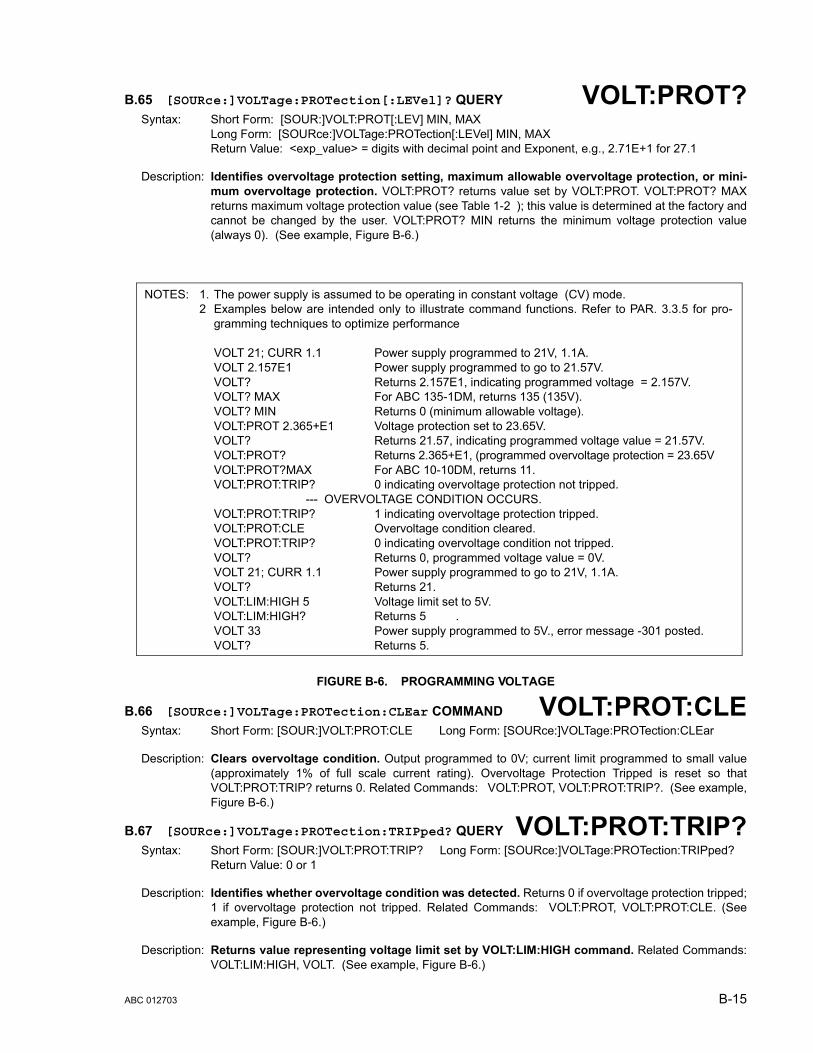
B.65 [SOURce:]VOLTage:PROTection[:LEVel]? QUERY VOLT:PROT?Syntax: Short Form: [SOUR:]VOLT:PROT[:LEV] MIN, MAX
Long Form: [SOURce:]VOLTage:PROTection[:LEVel] MIN, MAXReturn Value: <exp_value> = digits with decimal point and Exponent, e.g., 2.71E+1 for 27.1
Description: Identifies overvoltage protection setting, maximum allowable overvoltage protection, or mini-mum overvoltage protection. VOLT:PROT? returns value set by VOLT:PROT. VOLT:PROT? MAXreturns maximum voltage protection value (see Table 1-2 ); this value is determined at the factory andcannot be changed by the user. VOLT:PROT? MIN returns the minimum voltage protection value(always 0). (See example, Figure B-6.)
FIGURE B-6. PROGRAMMING VOLTAGE
B.66 [SOURce:]VOLTage:PROTection:CLEar COMMAND VOLT:PROT:CLESyntax: Short Form: [SOUR:]VOLT:PROT:CLE Long Form: [SOURce:]VOLTage:PROTection:CLEar
Description: Clears overvoltage condition. Output programmed to 0V; current limit programmed to small value(approximately 1% of full scale current rating). Overvoltage Protection Tripped is reset so thatVOLT:PROT:TRIP? returns 0. Related Commands: VOLT:PROT, VOLT:PROT:TRIP?. (See example,Figure B-6.)
B.67 [SOURce:]VOLTage:PROTection:TRIPped? QUERY VOLT:PROT:TRIP?Syntax: Short Form: [SOUR:]VOLT:PROT:TRIP? Long Form: [SOURce:]VOLTage:PROTection:TRIPped?
Return Value: 0 or 1
Description: Identifies whether overvoltage condition was detected. Returns 0 if overvoltage protection tripped;1 if overvoltage protection not tripped. Related Commands: VOLT:PROT, VOLT:PROT:CLE. (Seeexample, Figure B-6.)
Description: Returns value representing voltage limit set by VOLT:LIM:HIGH command. Related Commands:VOLT:LIM:HIGH, VOLT. (See example, Figure B-6.)
NOTES: 1. The power supply is assumed to be operating in constant voltage (CV) mode.2 Examples below are intended only to illustrate command functions. Refer to PAR. 3.3.5 for pro-
gramming techniques to optimize performance
VOLT 21; CURR 1.1 Power supply programmed to 21V, 1.1A.VOLT 2.157E1 Power supply programmed to go to 21.57V.VOLT? Returns 2.157E1, indicating programmed voltage = 2.157V.VOLT? MAX For ABC 135-1DM, returns 135 (135V).VOLT? MIN Returns 0 (minimum allowable voltage).VOLT:PROT 2.365+E1 Voltage protection set to 23.65V.VOLT? Returns 21.57, indicating programmed voltage value = 21.57V.VOLT:PROT? Returns 2.365+E1, (programmed overvoltage protection = 23.65VVOLT:PROT?MAX For ABC 10-10DM, returns 11.VOLT:PROT:TRIP? 0 indicating overvoltage protection not tripped.
--- OVERVOLTAGE CONDITION OCCURS.VOLT:PROT:TRIP? 1 indicating overvoltage protection tripped.VOLT:PROT:CLE Overvoltage condition cleared.VOLT:PROT:TRIP? 0 indicating overvoltage condition not tripped.VOLT? Returns 0, programmed voltage value = 0V.VOLT 21; CURR 1.1 Power supply programmed to go to 21V, 1.1A.VOLT? Returns 21.VOLT:LIM:HIGH 5 Voltage limit set to 5V.VOLT:LIM:HIGH? Returns 5 .VOLT 33 Power supply programmed to 5V., error message -301 posted.VOLT? Returns 5.
ABC 012703 B-15
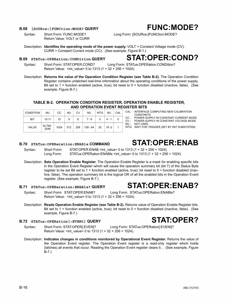
B.68 [SOURce:]FUNCtion:MODE? QUERY FUNC:MODE?Syntax: Short Form: FUNC:MODE? Long Form: [SOURce:]FUNCtion:MODE?
Return Value: VOLT or CURR
Description: Identifies the operating mode of the power supply. VOLT = Constant Voltage mode (CV). CURR = Constant Current mode (CC). (See example, Figure B-1.)
B.69 STATus:OPERation:CONDition QUERY STAT:OPER:COND?Syntax: Short Form: STAT:OPER:COND? Long Form: STATus:OPERation:CONDition?
Return Value: <int_value> 0 to 1313 (1 + 32 + 256 + 1024).
Description: Returns the value of the Operation Condition Register (see Table B-2). The Operation ConditionRegister contains unlatched real-time information about the operating conditions of the power supply.Bit set to 1 = function enabled (active, true); bit reset to 0 = function disabled (inactive, false). (Seeexample, Figure B-7.)
B.70 STATus:OPEReration:ENABle COMMAND STAT:OPER:ENABSyntax: Short Form: STAT:OPER:ENAB <int_value> 0 to 1313 (1 + 32 + 256 + 1024)
Long Form: STATus:OPERation:ENABle <int_value> 0 to 1313 (1 + 32 + 256 + 1024)
Description: Sets Operation Enable Register. The Operation Enable Register is a mask for enabling specific bitsin the Operation Event Register which will cause the operation summary bit (bit 7) of the Status Byteregister to be set Bit set to 1 = function enabled (active, true); bit reset to 0 = function disabled (inac-tive, false). The operation summary bit is the logical OR of all the enabled bits in the Operation Eventregister. (See example, Figure B-7.)
B.71 STATus:OPEReration:ENABle? QUERY STAT:OPER:ENAB?Syntax: Short Form: STAT:OPER:ENAB? Long Form: STATus:OPERation:ENABle?
Return Value: <int_value> 0 to 1313 (1 + 32 + 256 + 1024).
Description: Reads Operation Enable Register (see Table B-2). Returns value of Operation Enable Register bits.Bit set to 1 = function enabled (active, true); bit reset to 0 = function disabled (inactive, false). (Seeexample, Figure B-7.)
B.72 STATus:OPERation[:EVENt] QUERY STAT:OPER?Syntax: Short Form: STAT:OPER[:EVEN]? Long Form: STATus:OPERation[:EVENt]?
Return Value: <int_value> 0 to 1313 (1 + 32 + 256 + 1024).
Description: Indicates changes in conditions monitored by Operational Event Register. Returns the value ofthe Operation Event register. The Operation Event register is a read-only register which holds(latches) all events that occur. Reading the Operation Event register clears it. . (See example, FigureB-7.)
TABLE B-2. OPERATION CONDITION REGISTER, OPERATION ENABLE REGISTER,AND OPERATION EVENT REGISTER BITS
CONDITION NU CC NU CV NU WTG NU CAL
BIT 15-11 10 9 8 7 - 6 5 4 - 1 0
VALUE 32,768 - 2048 1024 512 256 128 - 64 32 16 -2 1
CAL - INTERFACE COMPUTING NEW CALIBRATIONCONSTANTS
CC - POWER SUPPLY IN CONSTANT CURRENT MODECV - POWER SUPPLY IN CONSTANT VOLTAGE MODENU - NOT USEDWTG WAIT FOR TRIGGER (SET BY INIT SUBSYSTEM)
B-16 ABC 012703

B.73 STATus:PRESet COMMAND STAT:PRESSyntax: Short Form: STAT:PRES Long Form: STATus:PRESet
Description: Disables reporting of all status events. This command sets all bits of the Operation Condition(Table B-2) and Questionable Condition Registers to 0, preventing all status events from beingreported. (See example, Figure B-7.)
FIGURE B-7. USING STATUS COMMANDS AND QUERIES
B.74 STATus:QUEStionable[:EVENt]? QUERY STAT:QUES?Syntax: Short Form: STAT:QUES[EVEN]? Long Form: STATus:QUEStionable[EVENT]?
Return Value: <int_value> actual register value
Description: Indicates questionable events that occurred since previous STAT:QUES? query. Returns thevalue of the Questionable Event register (see Table B-3). The Questionable Event register is aread-only register which holds (latches) all events. Reading the Questionable Event register clears it.(See example, Figure B-7.)
NOTE:The power supply is assumed to be operating in cV (constant voltage) mode.
STAT:OPER:ENAB 1056Mask enabled for CC, WTG and bits.STAT:OPER:ENAB? Returns 1056 (32 + 1024) (CC, WTG bits set).STAT:QUES:ENAB 3 Mask enabled for OV and OC bits (1 + 2).STAT:QUES:ENAB? Returns 3 (1 + 2) indicating OV and OC bits are enabled.STAT:PRES Operation Condition and Questionable Condition registers are
reset.INIT:CONT ON Continuous triggers enabled.STAT:OPER:COND? Power supply returns 288 (256 + 32) to indicate that power
supply is constant voltage mode and Wait For Trigger is true.STAT:OPER? Returns 1057, e.g., indicating that since the last reading of the
Operation Event Register the power supply has entered Constant Current mode, the Wait Trigger was set.
STAT:OPER? Returns 0 indicating no changes since previous reading of theOperation Event register.
STAT:QUES? Returns 0 (no questionable conditions occurred since previous reading
--- OVERCURRENT CONDITION OCCURSSTAT:QUES? Returns 2 (overcurrent protection tripped since the last
STAT:QUES? query).STAT:QUES:COND? Returns 2, (Power supply still in overcurrent protection state).STAT:QUES? Returns 0, (Register cleared by previous STAT:QUES?).STAT:QUES:COND? Returns 2, (Power supply still in overcurrent protection state).CURR:PROT:CLE Overcurrent condition cleared.STAT:QUES:COND? Returns 0, (register cleared by CURR:PROT:CLE).SYST:ERR? Power supply returns 0,“No error” message.
TABLE B-3. QUESTIONABLE EVENT REGISTER, QUESTIONABLE CONDITION REGISTERAND QUESTIONABLE CONDITION ENABLE REGISTER BITS
CONDITION NU OC OV
BIT 15 - 2 1 0
VALUE 32,768 - 4 2 1
OC - OVERCURRENT PROTECTION TRIPPEDOV - OVERVOLTAGE PROTECTION TRIPPEDNU - NOT USED
ABC 012703 B-17

B.75 STATus:QUEStionable:CONDition? QUERY STAT:QUES:COND?Syntax: Short Form: STAT:QUES:COND? Long Form: STATus:QUEStionable:CONDition?
Return Value: <int_value> actual register value
Description: Returns the value of the Questionable Condition Register (see Table B-3). The QuestionableCondition Register contains unlatched real-time information about questionable conditions of thepower supply. Bit set to 1 = condition (active, true); bit reset to 0 = condition (inactive, false). (Seeexample, Figure B-7.)
B.76 STATus::QUEStionable:ENABle COMMAND STAT:QUES:ENABSyntax: Short Form: STAT:QUES:ENAB <int_value> Long Form: STATus:QUESionable:ENABle <int_value>
Function: Programs Questionable Condition Enable Register.
Description: Programs Questionable Condition Enable Register (see Table B-3).The Questionable ConditionEnable Register determines which conditions are allowed to set the Questionable Condition Register;it is a mask for enabling specific bits in the Questionable Event register that can cause the question-able summary bit (bit 3) of the Status Byte register to be set. The questionable summary bit is the log-ical OR of all the enabled bits in the Questionable Event register. Bit set to 1 = function enabled(active, true); bit reset to 0 = function disabled (inactive, false). (See example, Figure B-7.)
B.77 STATus:QUEStionable:ENABle? QUERY STAT:QUES:ENAB?Syntax: Short Form: STAT:QUES:ENAB? Long Form: STATus:QUESionable:ENABle?
Return Value: <int_value> actual register value
Description: Reads Questionable Condition Enable Register (see Table B-3). Power supply returns value ofQuestionable Condition Enable Register, indicating which conditions are being monitored. Bit set to 1= function enabled (active, true); bit reset to 0 = function disabled (inactive, false). Related Com-mands: STAT:QUES?. (See example, Figure B-7.)
B.78 SYSTem:ERRor[:NEXT]? QUERY SYST:ERR?Syntax: Short Form: SYST:ERR[:NEXT]? Long Form: SYSTem:ERRor[:NEXT]?
Return Value: <int_value,string>
Description: Posts error messages to the output queue. Returns the next error number followed by its corre-sponding error message string from the instrument error queue. The error queue is a FIFO (first in firstout) buffer that stores errors as they occur. As it is read, each error is removed from the queue and thenext error message is made available. When all errors have been read, the query returns 0,"No error".If more than 15 errors are accumulated, it will overflow. The oldest errors stay in the queue but themost recent errors are discarded. The last error in the queue will be -350,"Too many errors." Errormessages are defined in Table B-4.
B.79 SYSTem:ERRor:CODE? QUERY SYST:ERR:CODE?Syntax: Short Form: SYST:ERR:CODE?] Long Form: SYSTem:ERRor:CODE?
Description: Returns the three character error code without the ASCII definition string. The error codes are definedin table B-4 (See example, Figure B-1.) The error bits defined in PAR A.3 through A.5 are related tothese error codes produced during parsing of messages and also to errors in the power supply as indi-cated in Table B-4.
B.80 SYSTem:ERRor:CODE:ALL? QUERY SYST:ERR:CODE:ALL?Syntax: Short Form: SYST:ERR:CODE:ALL?] Long Form: SYSTem:ERRor:CODE:ALL?
Return Value:
Description: Returns a comma-separated list of all error codes. A maximum of 15 codes will be returned; if thequeue is empty, the power supply returns 0.
B-18 ABC 012703
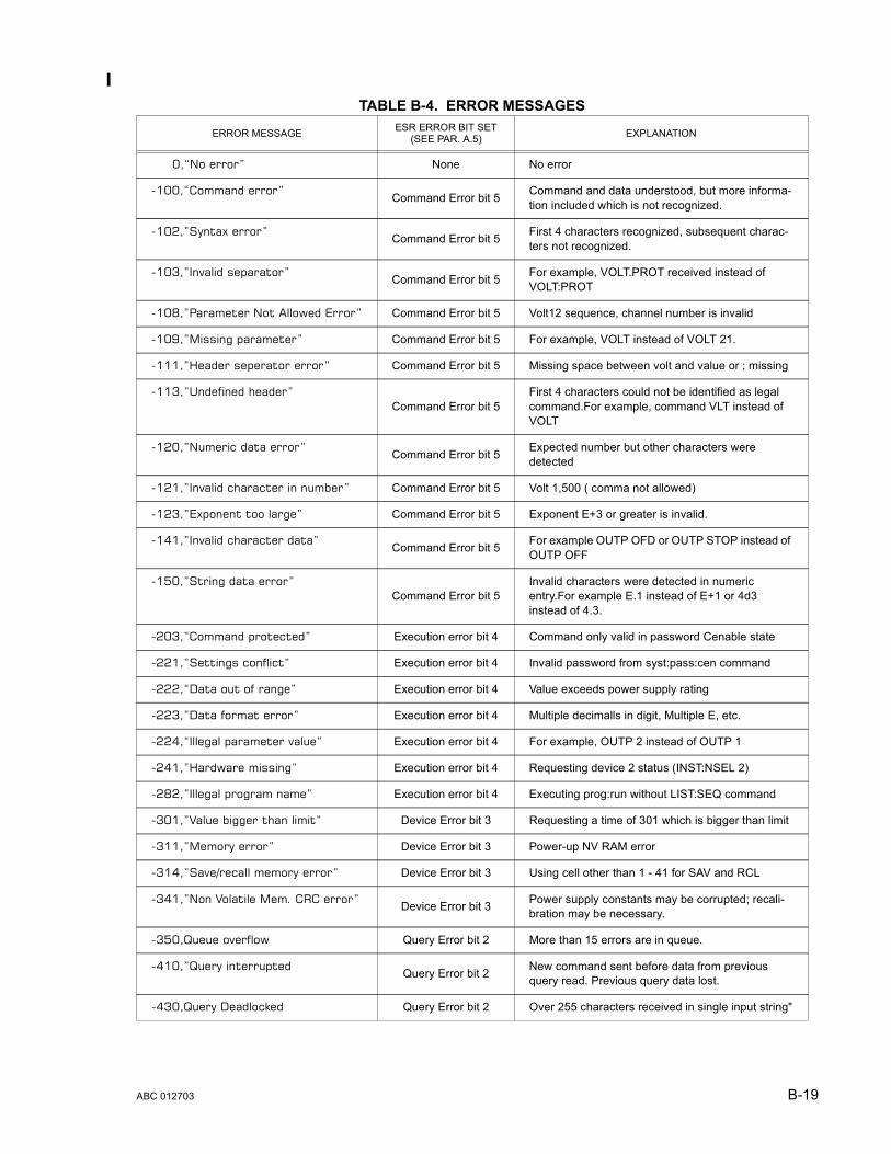
TABLE B-4. ERROR MESSAGES
ERROR MESSAGE ESR ERROR BIT SET(SEE PAR. A.5) EXPLANATION
0,“No error” None No error
-100,“Command error” Command Error bit 5 Command and data understood, but more informa-tion included which is not recognized.
-102,”Syntax error” Command Error bit 5 First 4 characters recognized, subsequent charac-ters not recognized.
-103,”Invalid separator” Command Error bit 5 For example, VOLT.PROT received instead of VOLT:PROT
-108,”Parameter Not Allowed Error” Command Error bit 5 Volt12 sequence, channel number is invalid
-109,”Missing parameter” Command Error bit 5 For example, VOLT instead of VOLT 21.
-111,”Header seperator error” Command Error bit 5 Missing space between volt and value or ; missing
-113,”Undefined header”Command Error bit 5
First 4 characters could not be identified as legal command.For example, command VLT instead of VOLT
-120,”Numeric data error” Command Error bit 5 Expected number but other characters were detected
-121,”Invalid character in number” Command Error bit 5 Volt 1,500 ( comma not allowed)
-123,”Exponent too large” Command Error bit 5 Exponent E+3 or greater is invalid.
-141,”Invalid character data” Command Error bit 5 For example OUTP OFD or OUTP STOP instead of OUTP OFF
-150,”String data error”Command Error bit 5
Invalid characters were detected in numeric entry.For example E.1 instead of E+1 or 4d3 instead of 4.3.
-203,”Command protected” Execution error bit 4 Command only valid in password Cenable state
-221,”Settings conflict” Execution error bit 4 Invalid password from syst:pass:cen command
-222,“Data out of range” Execution error bit 4 Value exceeds power supply rating
-223,”Data format error” Execution error bit 4 Multiple decimalls in digit, Multiple E, etc.
-224,“Illegal parameter value” Execution error bit 4 For example, OUTP 2 instead of OUTP 1
-241,”Hardware missing” Execution error bit 4 Requesting device 2 status (INST:NSEL 2)
-282,”Illegal program name” Execution error bit 4 Executing prog:run without LIST:SEQ command
-301,”Value bigger than limit” Device Error bit 3 Requesting a time of 301 which is bigger than limit
-311,”Memory error” Device Error bit 3 Power-up NV RAM error
-314,”Save/recall memory error” Device Error bit 3 Using cell other than 1 - 41 for SAV and RCL
-341,”Non Volatile Mem. CRC error” Device Error bit 3 Power supply constants may be corrupted; recali-bration may be necessary.
-350,Queue overflow Query Error bit 2 More than 15 errors are in queue.
-410,”Query interrupted Query Error bit 2 New command sent before data from previous query read. Previous query data lost.
-430,Query Deadlocked Query Error bit 2 Over 255 characters received in single input string"
ABC 012703 B-19

B.81 SYSTem:KLOCk COMMAND SYST:KLOCSyntax: Short Form: SYST:KLOC <boolean> Long Form: SYSTem:KLOCk <boolean>
<boolean> (0 or OFF, 1 or ON)
Description: Locks (ON or 1) or unlocks (OFF or 0) the keypad. With the keypad unlocked the power supplyenters Remote mode as soon as a command or query is received. Once in Remote mode (with key-pad unlocked) the front panel keys are disabled with the exception of the LOCAL key, which is used toreturn to Local mode.
After sending a SYST:KLOC ON (keypad lock) command, all front panel keys, including LOCAL, aredisabled. The power supply is now in the “local lockout” state and the LCD changes from Loc toRwl. Local lockout can also be entered by sending the GPIB <LLO> code (hex 11) to the power sup-ply. The power supply remains in “local lockout” until a SYST:KLOC OFF command is received.Related Commands: SYST:KLOCK?. (See example, Figure B-8.)
B.82 SYSTem:KLOCk? QUERY SYST:KLOC?Syntax: Short Form: SYST:KLOC? Long Form: SYSTem:KLOCk?
Return Value: <int_value> 0 or 1
Description: Identifies whether keypad is locked or unlocked. 0 = keypad unlocked, local operation possible bypressing LOCAL key. 1 = keypad locked, LOCAL key disabled, only remote operation possible.Related Commands: SYST:KLOCK. (See example, Figure B-8.)
B.83 SYSTem:LANGuage? QUERY SYST:LANG?Syntax: Short Form: SYST:LANG? Long Form: SYSTem:LANGuage?
Return Value: <string> SCPI or COMP
Description: Identifies whether unit responds to older command formats. SCPI means the unit will not respondto older formats such as LIST:TIME. COMP means the unit will respond to older formats such asLIST:TIME for compatible operation with software written for ABC power supplies up to Revision 1.
B.84 SYSTem:LANGuage COMMAND SYST:LANGSyntax: Short Form: SYST:LANG {COMP | SCPI} Long Form: SYSTem:LANGuage {COMP | SCPI}
Description:Determines whether unit responds to older command formats. SendingSYST:LANG COMP causes the unit to respond to older formats such as LIST:TIME for compatibleoperation with software written for ABC power supplies up to Revision 1. SYST:LANG COMP hasbeen selected at the factory to permit the VISA demonstration program (which uses older commandformats) to operate. SYST:LANG SCPI disables responses to older command formats.
B.85 SYSTem:PASSword:CENable COMMAND SYST:PASS:CENSyntax: Short Form: SYST:PASS:CEN <val> Long Form: SYSTem:PASSword:CENable <val>
Description: Sets the password enable state if the value matches the current password. This command allowsother commands such as *SAV 41 to operate.
B.86 SYSTem:PASSword:CDISable COMMAND SYST:PASS:CDISSyntax: Short Form: SYST:PASS:CDIS <val> Long Form: SYSTem:PASSword:CDISable <val>
Description: Clears the password enable state if the value matches the current password.
B.87 SYSTem:PASSword:STATe? QUERY SYST:PASS:STAT?Syntax: Short Form: SYST:PASS:STAT? Long Form: SYSTem:PASSword:STATe?
Return Value: <int_value> 0 or 1
Description: Returns a 1 if the password state is enabled or a 0 if it is disabled.
B-20 ABC 012703

B.88 SYSTem:SECurity:IMMediate COMMAND SYST:SEC:IMMSyntax: Short Form: SYST:SEC:IMM Long Form: SYSTem:SECurity:IMMediate
Description: Initializes all NVRAM variable to factory defaults. This includes all memory steps to be set to 0 volts,1.28% of full scale current, overvoltage and overcurrent to be set to Iomax+10%, time value to be setto 0, and next step equal to 0.).It also initializes the power -up state to have DC Output Control off (seePAR 3.3.2). The calibration password is reset per Table 4-1 Use master password (see below) If pass-word has been lost. Related Commands: SYST:PASS:CEN must be sent prior to this command
B.89 SYSTem:SET COMMAND SYST:SETSyntax: Short Form: SYST:SET {CM0 | CM1 | DC0 | DC1 | LF0 | LF1 | STR | RLX)
Long Form: SYSTem:SET {CM0 | CM1 | DC0 | DC1 | LF0 | LF1 | STR | RLX)
Description: Sending SYST:SET CM1 sets the unit to operate in compatible mode and have all GPIB functionscompatible with software version 1.2 and lower units. Sending SYST:SET CM0 sets the unit to be fullySCPI 1997 compliant.
Sending SYST:SET DC1 causes Device Clear to be identical to *RST command. Sending SYST:SETDC0 causes Device Clear to have no effect on output voltage, output current or output on/off state.
Sending SYST:SET LF1 causes the power supply to respond with line feed if read occurs with outputbuffer empty. Sending LF0 causes the power not to send a line feed if read occurs with output bufferempty (SCPI 1997 compliant).
Sending SYST:SET RLX allows the power supply to accept special debug and troubleshooting com-mands (for KEPCO use only - e.g., after sending SYST:SET RLX the power supply will respond to the$vda? command by returning the value of the internal D/A converter for voltage). Sending SYST:SETSTR disables the special debug and troubleshooting commands.
Related Commands: SYST:PASS:CEN - the password must be enabled prior to saving the SYST:SET configuration usingthe *SAV41 command..*SAV41 - this command saves the confiiguration established by SYST:SET and OUTP commands andrestores it upon power up.
B.90 SYSTem:VERSion QUERY SYST:VERS?Syntax: Short Form: SYST:VERS? Long Form: SYSTem:VERSion?
Return Value: <int_value>.<int_value> (YYYY.V)
Description: Identifies SCPI Version implemented. Returns SCPI Version number: YYYY = year, V = Revision number for specified year. (See example, Figure B-8.)
FIGURE B-8. USING SYTEM COMMANDS AND QUERIES
TABLE B-5. MASTER PASSWORDSMODEL PASSWORD MODEL PASSWORD MODEL PASSWORD
ABC 10-10 ..10 ABC 25-4 ..20 ABC 60-2 ..40
ABC 15-7 ..60 ABC 36-3 ..30 ABC 125-1 ..50
SYST:VERS Returns 1997.0.SYST:KLOC ON keypad locked, only remote control possible.SYST:KLOC? Returns 1 indicating keypad locked.SYST:KLOC OFF keypad unlocked, pressing LOCAL key allows Local mode
operation.SYST:KLOC? Returns 0 indicating keypad unlocked.
ABC 012703 B-21/(B-22 Blank)
