vol.10, no.2, pp.163–175, june 2016 doi 10.1007/s40069 …c).pdf · · 2018-01-06ctod crack tip...
TRANSCRIPT

Determination of Double-K Fracture Parameters of Concrete UsingSplit-Tension Cube: A Revised Procedure
Shashi Ranjan Pandey1), Shailendra Kumar2),*, and A. K. L. Srivastava1)
(Received December 22, 2015, Accepted March 15, 2016, Published online March 30, 2016)
Abstract: This paper presents a revised procedure for computation of double-K fracture parameters of concrete split-tension cube
specimen using weight function of the centrally cracked plate of finite strip with a finite width. This is an improvement over the
previous work of the authors in which the determination of double-K fracture parameters of concrete for split-tension cube test
using weight function of the centrally cracked plate of infinite strip with a finite width was presented. In a recent research, it was
pointed out that there are great differences between a finite strip and an infinite strip regarding their weight function and the
solution of infinite strip can be utilized in the split-tension specimens when the notch size is very small. In the present work,
improved version of LEFM formulas for stress intensity factor, crack mouth opening displacement and crack opening displacement
profile presented in the recent research work are incorporated. The results of the double-K fracture parameters obtained using
revised procedure and the previous work of the authors is compared. The double-K fracture parameters of split-tension cube
specimen are also compared with those obtained for standard three point bend test specimen. The input data required for
determining double-K fracture parameters for both the specimen geometries for laboratory size specimens are obtained using well
known version of the Fictitious Crack Model.
Keywords: split-tension cube test, three point bend test, concrete fracture, double-K fracture parameters, weight function,
cohesive stress, size-effect.
AbbreviationsCBM Crack band modelCCM Cohesive crack modelCT Compact tensionDGFM Double-G fracture modelDKFM Double-K fracture modelECM Effective crack modelFCM Fictitious crack modelFPZ Fracture process zoneLEFM Linear elastic fracture mechanicsSEM Size effect modelSIF Stress intensity factorSTC Split tension cubeTPBT Three point bend testTPFM Two parameter fracture modelWST Wedge splitting test
List of Notationsao Initial crack lengthAi Regression coefficientsac Effective crack length at peak (critical) loadB Width of beamBi Regression coefficientsc1, c2 Material constants for nonlinear softening
functionCMOD Crack mouth opening displacementCMODc Crack mouth opening displacement at critical
loadCTOD Crack tip opening displacementCTODc Crack tip opening displacement at critical
loadD Depth or characteristic dimension of
specimenE Modulus of elasticity of concreteft Uniaxial tensile strength of concreteGF Fracture energy of concreteG(x,a) Weight functionH Height or total depth (2D) for split tension
cube specimenk(a, b) Non-dimensional function for KI or geometry
factorKI Stress intensity factorKICini Initial cracking toughness
KICun Unstable fracture toughness
1)Department of Civil Engineering, National Institute of
Technology, Jamshedpur, Jharkhand 831014, India.2)Department of Civil Engineering, Institute of
Technology, Guru Ghasidas Vishwavidyalaya
(A Central University), Bilaspur, CG 495009, India.
*Corresponding Author; E-mail:
Copyright � The Author(s) 2016. This article is published
with open access at Springerlink.com
International Journal of Concrete Structures and MaterialsVol.10, No.2, pp.163–175, June 2016DOI 10.1007/s40069-016-0139-6ISSN 1976-0485 / eISSN 2234-1315
163
KICC Cohesive toughness
m(x,a) Universal weight functionM1, M2, M3 Parameters of weight functionPu Maximum applied load or critical loadS Span of beamt Half of the width of distributed load for split
tension cube specimenV(a,b) Dimensionless function for CMODwc Maximum crack opening displacement at the
crack-tip for which the cohesive stressbecomes equals to zero
a Ratio of crack length to depth of specimen (a/D)
b Ratio of load-distributed to height ofspecimen (2t/h = t/D) for split tension cubespecimen
r Cohesive stresst The Poisson’s ratiors(CTODc) Cohesive stress at the tip of initial notch
corresponding to CTODc
1. Introduction
It is well known that fracture parameters of quasibrittlematerial like concrete cannot be determined by directlyapplying the concepts of linear elastic fracture mechanics(LEFM) because of the existence of large and variable sizeof fracture process zone (FPZ) ahead of a crack-tip. In orderto account for and characterize FPZ in the analysis, severalnon-linear fracture mechanics models have been developedwhich primarily involve cohesive crack model (CCM) orfictitious crack model (FCM) (Hillerborg et al. 1976; Modeer1979; Petersson 1981; Carpinteri 1989; Planas and Elices1991; Zi and Bazant 2003; Roesler et al. 2007; Park et al.2008; Zhao et al. 2008; Kwon et al. 2008, Cusatis andSchauffert 2009, Elices et al. 2009; Kumar and Barai 2008b,2009b) and crack band model (CBM) (Bazant and Oh 1983),two parameter fracture model (TPFM) (Jenq and Shah1985), size effect model (SEM) (Bazant et al. 1986), effec-tive crack model (ECM) (Nallathambi and Karihaloo 1986),KR-curve method based on cohesive force distribution (Xuand Reinhardt 1998, 1999a), double-K fracture model(DKFM) (Xu and Reinhardt 1999a, b, c) and double-Gfracture model (DGFM) (Xu and Zhang 2008).In recent time, much of research and studies (Xu and
Reinhardt 1999a, b, c, 2000; Zhao and Xu 2002; Zhang et al.2007; Xu and Zhu 2009; Kumar and Barai 2008a, 2009a,2010; Kumar 2010; Zhang and Xu 2011; Kumar and Pandey2012; Hu and Lu 2012; Murthy et al. 2012; Hu et al. 2012;Ince 2012; Kumar et al. 2013; Choubey et al. 2014; Kumaret al. 2014) have been carried out to determine and charac-terize the fracture parameters of concrete using double-Kfracture model for which the reasons are obvious (Kumaret al. 2013). The double-K fracture model is characterized bytwo material parameters: initial cracking toughness KIC
ini andunstable fracture toughness KIC
un. The initiation toughness isdefined as the inherent toughness of the materials, which
holds for loading at crack initiation when material behaveselastically and micro cracking is concentrated to a small-scale in the absence of main crack growth. It is directlycalculated by knowing the initial cracking load and initialnotch length using LEFM formula. The total toughness atthe critical condition is known as unstable toughness KIC
un
which is regarded as one of the material fracture parametersat the onset of the unstable crack propagation and it can beobtained by knowing peak load and corresponding effectivecrack length using the same LEFM formula. Recently,Kumar and Pandey (2012) presented the formulation anddetermination of double-K fracture parameters using split-tension cube test specimen using weight function method inwhich the LEFM formulas for stress intensity factor (SIF),crack mouth opening displacement (CMOD) and crackopening displacement (COD) profile derived by Ince (2010)and the universal weight function of Wu et al. (2003) wereadopted. The authors (Kumar and Pandey 2012) mentionedthat there are several advantages of using split-tension cube(STC) test specimen over the testing of other specimens likethree point bend test (TPBT), compact tension (CT) andwedge splitting test (WST) specimens. However, thereshould be a limitation that the notch can be only produced atthe time of casting of concrete cubes (pre-cast notch) in thesplit tension cube specimen. The authors also presented theresults of the initial cracking toughness, cohesive toughnessand unstable fracture toughness obtained using split tensioncube test specimen and they were compared with thoseobtained using standard compact tension specimen. From thestudy it was concluded that the double-K fracture parametersas obtained using split-tension cube test are in good agree-ment and consistent with those as calculated using standardcompact tension specimen. However, the results of fractureparameters are influenced by the distributed-load widthduring the loading of split-tension cube specimen and it wasobserved that the values of unstable fracture toughness andcohesive toughness increase with increase in the distributed-load width whereas the initial cracking toughness is notsignificantly affected by the distributed-load width. In theformulation, the authors (Kumar and Pandey 2012) used theweight function of the centrally cracked infinite strip with afinite width specimen (Tada et al. 2000) and the equivalentfour terms of universal weight function (Wu et al. 2003) forcomputing the value of cohesive toughness and conse-quently determining the initial cracking toughness. Later,Ince (2012) put forward a method for determination ofdouble-K fracture parameters using weight function forsplit—tension specimens such as splitting tests on cubical,cylindrical and diagonal cubic concrete samples. The authorpointed out that there are great differences between a finitestrip and an infinite strip regarding their weight function andthe solution of infinite strip can be utilized in the split-ten-sion specimens when the notch size is very small. It wasconcluded that the central cracked plate can be considered asan infinite strip when the length/width (l/D) ratio of a plate isequal or greater than 3 (Isida 1971, Tada et al. 2000). In caseof a cube-split tension test specimen the value of the length/characteristic dimension (l/D) ratio is taken to be 1 for which
164 | International Journal of Concrete Structures and Materials (Vol.10, No.2, June 2016)
Ince (2012) derived the four term universal weight functionusing boundary element method and finite element method.The author also presented the improved version of LEFMformulas for stress intensity factor, CMOD and COD profileover the previously derived LEFM equations by the sameauthor (Ince 2010) for split tension cube test specimen. Inview of the above development, it was felt necessary to carryout a comparative study on the double-K fracture parameterscomputed using the procedure outlined by Kumar andPandey (2012) and using the weight function of the centrallycracked plate of finite strip with a finite width incorporatingthe improved version of LEFM formulas for stress intensityfactor, CMOD and COD profile derived by Ince (2012).The paper presents the revised procedure for determination
of double-K fracture model using weight function method forthe split-tension cube specimen of concrete consideringimproved LEFM formulas for stress intensity factor, CMODand COD profile and the weight function of the centrallycracked plate of finite strip with a finite width derived byInce (2012). The results of the fracture parameters obtainedusing revised procedure and the previous work of Kumarand Pandey (2012) are compared. Further, the double-K fracture parameters of split-tension cube specimen are alsocompared with those obtained for standard three point bendtest specimen. The input data required for determining forsplit-tension cube test and three point bend test for labora-tory size specimens are obtained using well known versionof the fictitious crack model.
2. Dimensions of Test Specimens
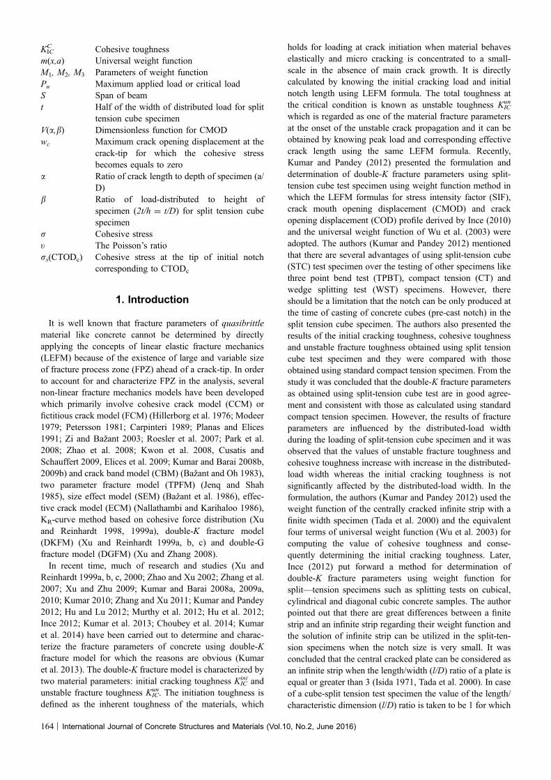
For present investigation, the standard test geometries,dimensions and loading conditions for STC and TPBT spec-imens are considered as shown in Fig. 1. The symbols inFig. 1(a): ao, D, h and t are half of the initial notch-length,characteristic dimension as specimen size (D = h/2), heightor total depth and half of the width of distributed loadrespectively for STC geometry. RILEM Technical Committee50-FMC (1985) has recommended the guidelines for deter-mination of fracture energy of cementitous materials usingstandard three-point bend test on notched beam. This methodhas been widely used for determination of fracture energy ofconcrete with certain modification in the experimental setup(Lee and Lopez 2014). In present study, standard three—pointbend test (RILEM Technical Committee 50-FMC 1985) isconsidered forwhich the symbols:B,D and S in Fig. 1b are thewidth, depth and span respectively with S/D = 4.
3. Determination of Double-K FractureParameters for STC Specimen
3.1 AssumptionsLinear asymptotic superposition assumption is considered
to introduce LEFM for calculating the double-K fractureparameters. The hypotheses of the assumption are givenbelow:
(ii) Mid span cross-section
(b)
ao D
B
S = 4D
P
(i) Longitudinal section
h
2t
D
D
D D P
P
ao
ao
(a)
h
Fig. 1 Dimensions and loading schemes for STC and TPBT test specimens. a Split tension cube test specimen, b Dimensionsand loading schemes of TPBT.
International Journal of Concrete Structures and Materials (Vol.10, No.2, June 2016) | 165

1. the nonlinear characteristic of the load-crack mouthopening displacement (P-CMOD) curve is caused byfictitious crack extension in front of a stress-free crack; and
2. an effective crack consists of an equivalent-elasticstress-free crack and equivalent-elastic fictitious crackextension.
A detailed explanation of the hypotheses may be seenelsewhere (Xu and Reinhardt 1999b).
3.2 Effective Crack ExtensionFor the applied load (Fig. 1) on the STC specimen, the
critical value of CMOD (CMODc) is measured across thecrack faces at the centre of specimen. The P-CMOD curveup to peak load for this test geometry should be known apriori for determining the value of effective crack extensionduring the crack propagation. Using linear asymptoticsuperposition assumption, the equivalent-elastic crack lengthac corresponding to maximum load Pu is solved using therevised LEFM formulae (Ince 2012). Hence, the CMOD isexpressed as:
CMOD ¼ pDrN
EaV a; bð Þ ð1Þ
V ða; bÞ ¼ B0ðbÞ þ B1ðbÞaþ B2ðbÞa2 þ B3ðbÞa3þ B4ðbÞa4 þþB5ðbÞa5 ð2Þ
In which a = a/D, b is the relative load-distributed widthand expressed as b = 2t/h = t/D, V(a,b) is dimensionlessgeometric function, coefficients Bi (i = 0 to 5) are thefunction of b as given in Table 1. Equation (2) is valid for0.1 B a B 0.9 within 0.3 % accuracy for 0 B b B 0.2. Themodulus of elasticity of concrete (E) obtained using cylindertest is taken as a constant value for a particular concrete mix.Ince (2012) used boundary element numerical method toimprove the LEFM formulas over the previous LEFM
formulas (Ince 2010) for the split tension cube specimenswhich was based on centrally cracked infinite strip with afinite width specimen. Equation (2) and Table 1 used in thepresent study are extracted by Ince (2012) from thenumerical results based on centrally cracked finite stripwith a finite width specimen. Since the values of coefficientsBi (Table 1) are given (Ince 2012) at discrete intervals, thesecoefficients can be determined by linear interpolation at anyvalue of b for the given range 0 B b B 0.2.
Also, the nominal stress for STC test specimen in Eq. (1)can be written using the following formula (Timoshenko andGoodier 1970).
rN ¼2P
pBhð3Þ
At critical condition that is at maximum load Pu the half ofcrack length a becomes equal to ac and rN to rNu in whichrNu is the maximum nominal stress. Karihaloo andNallathambi (1991) concluded that almost the same valueof E might be obtained from P-CMOD curve, load–deflection curve and compressive cylinder test. Hence, incase that is not known the value of E determined usingcompressive cylinder tests may be used to obtain the criticalcrack length of the specimen.
3.3 CalculationofDouble-KFractureParametersA linearly varying cohesive stress distribution is assumed
in the fictitious crack zone, which gives rise to cohesiontoughness as a part of total toughness of the cracked body.Superposition method is used in order to calculate thestress intensity factor (SIF) at the tip of effective cracklength KI. According to this method, total stress intensityfactor KI is taken as the summation of stress intensityfactor caused due to external load KI
P and stress intensityfactor contributed by cohesive stress KI
C- as shown in
Table 1 The values of coefficients Ai and Bi for split- tension cube specimen (Ince 2012).
b = t/D
Coefficient 0.0 0.067 0.1 0.133 0.167 0.2
A0 0.842 0.995 1.050 1.060 1.036 0.995
A1 2.861 -0.147 -1.366 -1.815 -1.655 -1.219
A2 -17.384 1.847 9.772 12.762 11.794 8.986
A3 53.695 -0.480 -23.296 -32.385 -30.268 -22.774
A4 -70.864 -1.908 27.794 40.275 38.365 29.263
A5 35.033 2.429 -12.082 -18.691 -18.479 -14.669
B0 1.159 1.192 1.211 1.216 1.208 1.188
B1 1.974 1.160 0.582 0.175 -0.047 -0.133
B2 -11.204 -5.970 -2.239 0.397 1.834 2.379
B3 37.233 22.364 11.650 3.942 -0.417 -2.252
B4 -48.035 -29.008 -15.160 -5.051 0.803 3.389
B5 23.823 14.741 8.015 2.972 -0.093 -1.597
166 | International Journal of Concrete Structures and Materials (Vol.10, No.2, June 2016)

Fig. 2. The value of KI is expressed in the followingexpression:
KI ¼ KPI þ KC
I ð4Þ
After determining the critical effective crack extension atunstable condition of loading, the unstable fracturetoughness KIC
un is determined using the revised LEFMformulae (Ince 2012) for which the stress intensity factoris expressed as:
KI ¼ rN
ffiffiffiffi
Dp
ffiffiffiffiffiffi
pap
kða; bÞ ð5Þ
kða; bÞ ¼ A0ðbÞ þ A1ðbÞaþ A2ðbÞa2 þ A3ðbÞa3þ A4ðbÞa4 þ A5ðbÞa5 ð6Þ
where k(a, b) is a geometric factor and coefficients Ai
(i = 0–5) are the function of b as summarized in Table 1.
Equation (6) yields results within 0.7 % accuracy for0.1 B a B 0.9 and 0 B b B 0.2. Within the range of0 B b B 0.2, any value of coefficients Ai can be determinedby linear interpolation. The unstable fracture toughness KIC
un
is calculated using Eq. (5) at maximum load Pu when a be-comes equal to ac and rN to rNu.If the crack initiation load Pini is known from experiment,
the initiation toughness KICini is calculated using Eq. (5) in
which P is equal to Pini and a is equal to ao. Alternatively, itcan be determined analytically by applying the followingrelation.
KiniIC ¼ Kun
IC � KCIC ð7Þ
Equation (7) is known as inverse method for determining theinitiation toughness.
4. Determination of SIF Due to CohesiveStress
4.1 Cohesive Stress DistributionThe cohesive stress acting in the fracture process zone on
STC test specimen is idealized as series of pair normal forcessubjected symmetrically to central cracked specimen of finitestrip and a finite width as shown in Fig. 3. The linearlyvarying distribution of cohesive stress is also shown inFig. 4.A centrally cracked specimen with finite strip of a finite
width plate subjected to pair of normal forces as shown inFig. 3 takes into consideration for a split tension test cubespecimen where the value of the length/characteristicdimension (l/D) ratio becomes 1. The SIF due to cohesivestress distribution as shown in Fig. 4 becomes to cohesivetoughness KIC
C of the material at the critical loading conditionwith negative value because of closing stress in fictitiousfracture zone. However, the absolute value of KIC
C is taken asa contribution of the total fracture toughness (Xu andReinhardt 1999b) at the critical condition.At this loading condition, the crack-tip opening displace-
ment (CTOD) is termed as critical crack-tip opening dis-placement (CTODc). In Fig. 4, the rs(CTODc) is cohesivestress at the tip of initial notch where CTOD is equal toCTODc and then r(x) can be expressed as:
a
a
D
D
P
P
D D
KIP
= (b)
+ (c)
a
a
D
D
ao
(x)
ao
D D
KIC
(a)
a
a
D
D
ao
(x)
ao
P
P
D D
KI
Fig. 2 Calculation of SIF using superposition method.
a
a
x
DP P
D
xP P
ll
Fig. 3 Central cracked specimen with finite strip of a finitewidth plate subjected to pair of normal forces.
International Journal of Concrete Structures and Materials (Vol.10, No.2, June 2016) | 167

rðxÞ ¼ rsðCTODcÞ þx� aoa� ao
ft � rsðCTODcÞ½ �
for 0�CTOD�CTODc ð8Þ
The value of rs(CTODc) is calculated using softeningfunctions of concrete. In the present work, the nonlinearsoftening function (Reinhardt et al. 1986) is used for thecomputation which can be expressed as:
rðwÞ
¼ ft 1þ c1w
wc
� �3" #
exp�c2wwc
� �
� w
wc1þ c31� �
exp �c2ð Þ( )
ð9Þ
The value of total fracture energy of concrete GF isexpressed as:
GF ¼wcft1
c21þ6
c1c2
� �3" #
� 1þc31 1þ 3
c2þ 6
c22þ 6
c32
� �� �
(
exp �c2ð Þc2
� 1þc312
� �
exp �c2ð Þ
ð10Þ
In which, r(w) is the cohesive stress at crack openingdisplacement w at the crack-tip and c1 and c2 are the materialconstants. Also, w = wc for ft = 0, i.e., wc is the maximumcrack opening displacement at the crack-tip at which thecohesive stress becomes to be zero. The value ofwc is computedusingEq. (10) for a given set of values c1, c2 andGF. For normalconcrete the value of c1 and c2 is taken as 3 and 7, respectively.
4.2 Determination of CTODc
For a given value of critical crack mouth opening dis-placement CMODc, the crack opening displacement withinthe crack length COD(x) is computed using the revisedexpression (Ince 2012) as given below.
CODðxÞ ¼ CMODc
� 1� x
a
�2þ 1:967� 0:454 1þ bð Þ6:363a1:984 x
a
�1:913� ��
� x
a� x
a
�2� �2
)1=2
ð11Þ
The accuracy of Eq. (11) is greater than 4 % for0.1 B a B 0.9 and any value of b and is greater than2.5 % for 0.1 B a B 0.6 and any value of b. The value ofx is taken as ao and a as ac for evaluation of CTODc usingEq. (11).
4.3 Calculation of Cohesive Toughness UsingWeight Function ApproachAccording to weight function approach (Bueckner 1970,
Rice 1972), the SIF for mode –I loading is given by fol-lowing expression.
KI ¼Z
a
0
rðxÞ:mðx; aÞdx ð12Þ
where r(x) is the distribution of stress along the crack line xin the uncracked body, the term m(x,a) is known as weightfunction, a is the crack length and dx is the infinitesimallength along the crack surface. The four term universal formof weight function (Glinka and Shen 1991, Kumar and Barai2008a, 2009a, 2010) is written as:
mðx; aÞ ¼ 2ffiffiffiffiffiffiffiffiffiffiffiffiffiffiffiffiffiffiffiffi
2pða� xÞp
� 1þM1ð1� x=aÞ1=2 þM2ð1� x=aÞ þM3ð1� x=aÞ3=2h i
ð13Þ
For centrally through cracked specimen of infinite stripand a finite width subjected to pairs of normal forcessymmetrically (Fig. 3), the weight function as given by Tadaet al. (2000) is expressed as:
Gðx; aÞ ¼ 2ffiffiffiffiffiffi
2Dp 1þ 0:297
ffiffiffiffiffiffiffiffiffiffiffiffiffiffiffiffiffiffiffi
1� x
a
�2r
1� cospa2D
�h i
( )
Fa
D;x
a
�
Fa
D;x
a
�
¼ffiffiffiffiffiffiffiffiffiffiffiffiffiffiffiffiffiffi
tanpa2D
�
r
� 1�cos pa
2D
cos px2D
� �2" #�1=2
Equation (14) as equivalently expressed in terms ofuniversal weight function m(x,a) of Eq. (13) by Wu et al.(2003) was used by Kumar and Pandey (2012) in theprevious formulation. In the present investigation the weightfunction parameters M1, M2 and M3 derived by Ince (2012)for the split tension cube specimen are used. According toInce (2012) the parameters of four term weight function for acentrally through cracked specimen of finite strip and a finitewidth subjected to pairs of normal forces (Fig. 3) can beobtained as:
Mi ¼ mi0 þ mi1aþ mi2a2 þ mi3a
3 þ mi4a4 þ mi5a
5
þ mi6a6 þ mi7a
7 ð15Þ
where a = a/D and mij (i = 1–3 and j = 0–7) are thecoefficients of the polynomial Eq. (15) as presented in
a
a= ac
xD
D
x
ao
(x)
s(CTODc)
ft
ao
ll
Fig. 4 Distribution of cohesive stress in the fictitious crackzone at critical load.
168 | International Journal of Concrete Structures and Materials (Vol.10, No.2, June 2016)

Table 2. The sixth degree polynomial (mi7 = 0) is used forM2. Equation (15) is valid for 0 B a/D B 0.9 and 0 B x/a 1(exactly 0.993). The accuracy of Eqs. (13) and (15) isgreater than 3 % for all the split—tension cube specimens.Once the weight function parameters are determined,
Eq. (12) is used to calculate the SIF at critical condition(cohesive toughness) due to trapezoidal cohesive stressdistribution as shown in Fig. 4. The value of r(x) in Eq. (12)is replaced by Eq. (8), hence the closed form expression ofKICC can be obtained in the following form.
KCIC ¼
2ffiffiffiffiffiffiffiffi
2pap A1a 2s1=2 þM1sþ
2
3M2s
3=2 þM3
2s2
��
þ 2
5M4s
5=2
�
þ A2a2 4
3s3=2 þM1
2s2 þ 4
15M2s
5=2
�
þ 4
35M4s
7=2 þM3
61� ðao=aÞ3 � 3sao=an o
�
ð16Þ
where, A1 ¼ rsðCTODcÞ;A2 ¼ ft�rsðCTODcÞa�ao and s ¼ ð1�
ao=aÞ, also a = ac at P = Pu. After computing the value ofKICC using Eq. (16), initiation toughness can be evaluated
using Eq. (7).
5. Fictitious Crack Model and MaterialProperties for Double-K Fracture Model
The cohesive crack model (Modeer 1979; Petersson 1981;Carpinteri 1989; Planas and Elices 1991; Zi and Bazant
2003; Roesler et al. 2007, Park et al. 2008, Zhao et al. 2008,Kwon et al. 2008; Cusatis and Schauffert 2009; Elices et al.2009; Kumar and Barai 2008b, b) is developed for STC andTPBT specimens to determine the input data such as Pu andCMODc for these specimens. Three material properties suchas modulus of elasticity E, uniaxial tensile strength ft, andfracture energy GF are required to model FCM. In thismethod, the governing equation of COD along the potentialfracture line is written. The influence coefficients of theCOD equation are determined using linear elastic finiteelement method. Four noded isoparametric plane elementsare used in finite element calculation. The COD vector ispartitioned according to the enhanced algorithm introducedby Planas and Elices (1991). Finally, the system of nonlinearsimultaneous equation is developed and solved using New-ton–Raphson method. For standard STC and TPBT speci-mens with B = 100 mm having size range D = 200-500 mm, the finite element analysis is carried out for whichthe one-quarter of STC and half of TPBT specimens arediscretized due to symmetry as shown in Fig. 5 considering80 numbers of equal isoparametric plane elements along thecharacteristic dimension D. In the discretization, both thespecimens are divided into three bands perpendicular tocharacteristic dimension D such as D/4, D/4 and D/2 in caseof STC specimen and 0.25D, 0.75D and D in case of TPBTspecimen as shown in Fig. 5. This arrangement facilitates toobtain finer mesh size near the potential fracture line. ForSTC specimen, the number of divisions is taken as 20, 5 and5 in the bands D/4, D/4 and D/2 respectively whereas it is20, 10 and 5 in the bands 0.25D, 0.75D and D respectivelyfor TPBT specimen. Ten nodes from top along the potential
Table 2 Coefficients mij (j = 0–7) of the four term universal weight function parameters M1, M2 and M3 (Ince 2012).
Mi 0 1 2 3 4 5 6 7
1 0.070 0.407 -5.405 49.393 -199.837 384.617 -359.928 132.792
2 -0.089 -2.017 24.839 -86.042 207.787 -243.596 114.431
3 0.432 2.581 -31.022 134.511 -329.531 437.642 -292.768 69.925
(a)
D/4 D/2
D
P/2 t
D/4 D/4 0.75D D
D
P/2
(b)
Fig. 5 Finite element discretization of test geometries. a Split tension cube test specimen, b Three point bend test specimen.
International Journal of Concrete Structures and Materials (Vol.10, No.2, June 2016) | 169
fracture line are restrained against horizontal movement andall the nodes at the bottom perpendicular to fracture line arerestrained against vertical movement in case of STC speci-men. For the TPBT specimen, three nodes from top along thepotential fracture line are restrained in horizontal direction.The concrete mix with material properties: m = 0.18,ft = 3.21 MPa, E = 30 GPa, and GF = 103 N/m along withnonlinear stress-displacement softening relation with c1 = 3and c2 = 7 are used as the input parameters of FCM.From simulation of FCM, the results of peak load Pu
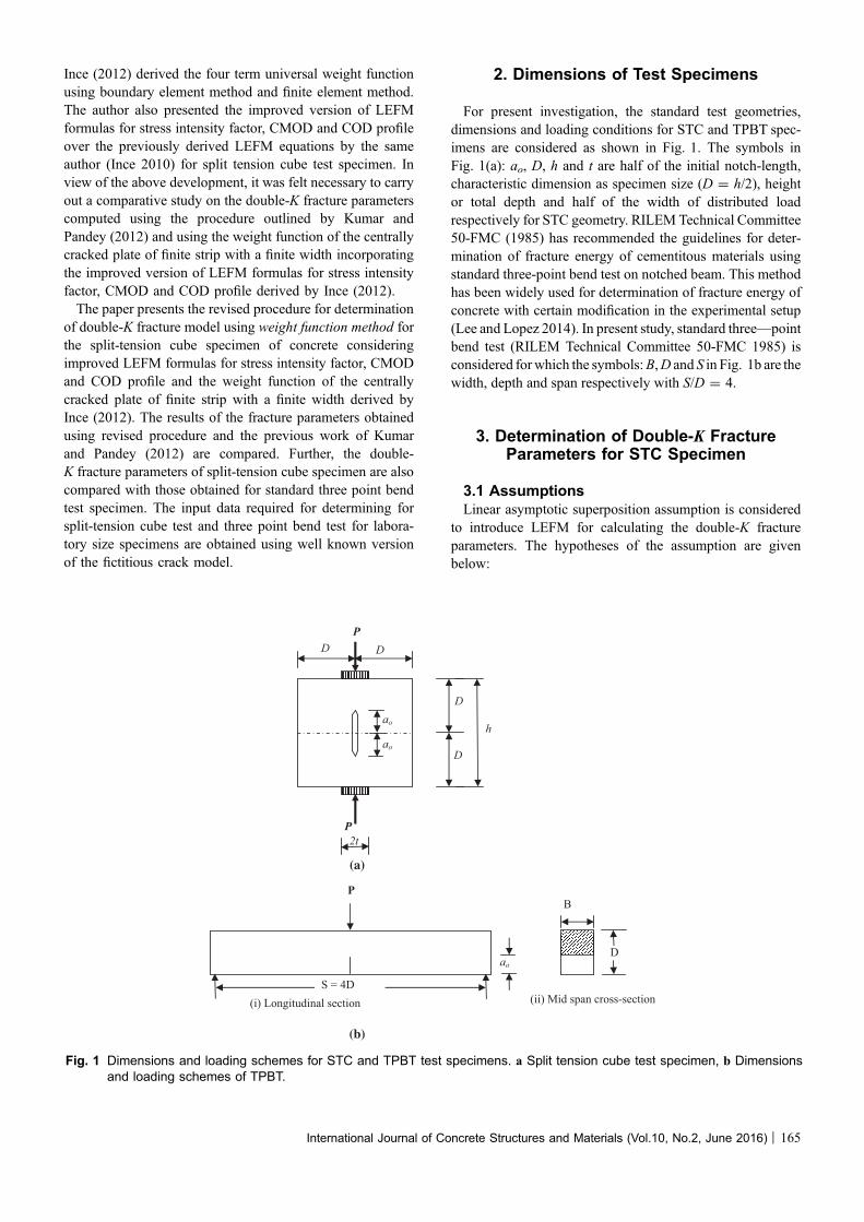
versus CMODc for TPBT specimen at a constant ao/D ratioof 0.3 are presented in Table 3. Similar results of peak loadPu and the corresponding CMODc at different load dis-tributed widths (b = 0.0, 0.05, 0.1 and 0.15) for STCspecimens of varying sizes (200–500 mm) at a constant ao/D ratio of 0.3 are also presented in Table 3.
6. Results and Discussion
The input parameters such as Pu, CMODc, E and softeningfunction of concrete are required from the tests for deter-mining double-K fracture parameters of concrete usingweight function analytical method. In the present study, thevalues of E, ft, nonlinear softening function (Eq. (9)) as
mentioned in Sect. 5 and the values of Pu-CMODc for STCand TPBT specimens obtained from FCM are used todetermine double-K fracture parameters. The weight functionmethod with four terms is applied to calculate double-K fracture parameters in which the value of critical crackextension ac is obtained using improved Eq. (1) for STCspecimen. For given values of ac and CMODc, the values ofCTODc are determined using revised Eq. (11). The values ofac and CTODc are also determined using correspondingequations presented in the previous work of Kumar andPandey (2012) which were based on LEFM equations givenby Ince (2010). The values of ac and CTODc for TPBTspecimen are determined as mentioned elsewhere (Kumarand Barai 2008a, 2010). All the values of ac and CTODc
determined as above are plotted in Figs. 6 and 7, respec-tively. For determining the value of KIC
C using weight func-tion method, first of all the four parameters M1, M2 and M3
of four terms weight function are computed using Eq. (15)and Table 2, then closed form expression (Eq. (16)) is usedto obtain the value of KIC
C and finally the KICini is determined
using inverse procedure (Eq. (7)). For TPBT specimen,double-K fracture parameters are determined in a similarmanner using four terms weight function method as men-tioned elsewhere (Kumar and Barai 2008a, 2010). Thus thevalues of KIC
un, KICC and KIC
ini as obtained for STC for different
Table 3 Values of Pu and CMODc obtained from FCM for TPBT and STC specimens for different specimen sizes.
D (mm) ao/D Pu (kN) CMODc (mm)
For TPBT For STC specimen For TPBT For STC specimen
Value of b for STC Value of b for STC
0.0 0.05 0.1 0.15 0.0 0.05 0.1 0.15
500 0.3 10.73 20.66 20.81 21.24 21.96 0.0822 0.0426 0.0427 0.0442 0.0449
400 0.3 9.47 17.56 17.69 18.074 18.72 0.0720 0.0379 0.0380 0.0385 0.0403
300 0.3 7.94 14.15 14.27 14.604 15.18 0.0624 0.0316 0.0318 0.0323 0.0340
200 0.3 6.05 10.33 10.43 10.724 11.23 0.0510 0.0243 0.0251 0.0259 0.0288
0.39
0.4
0.41
0.42
0.43
0.44
0.45
0.46
0.47
0.48
0 100 200 300 400 500 600
a c/D
D (mm)
STC-0.0
STC*-0.0
STC-0.05
STC*-0.05
STC-0.1
STC*-0.1
STC-0.15
STC*-0.15
TPBT
Fig. 6 Comparison in the values of ac/D for STC obtained using the previous method (Kumar and Pandey 2012) and the presentrevised method.
170 | International Journal of Concrete Structures and Materials (Vol.10, No.2, June 2016)
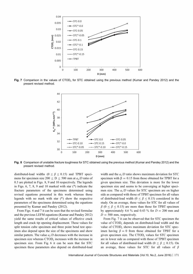
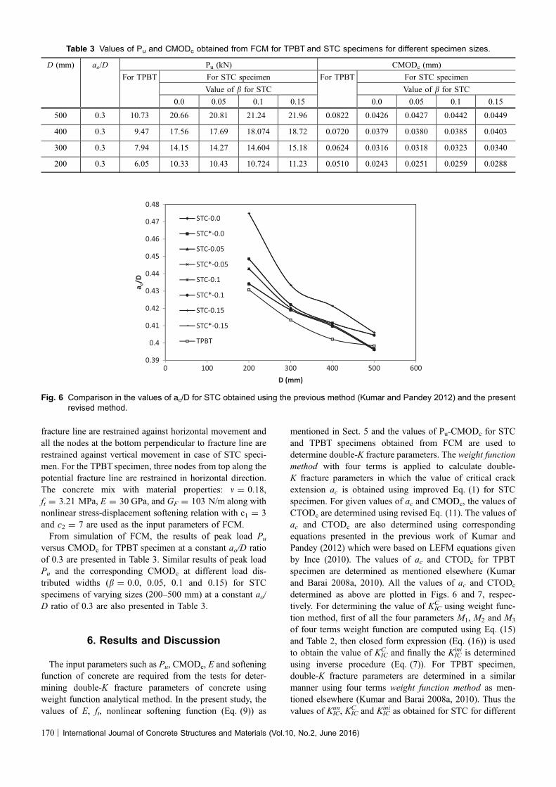
distributed-load widths (0 B b B 0.15) and TPBT speci-mens for specimen size 200 B D B 500 mm at ao/D ratio of0.3 are plotted in Figs. 8, 9 and 10 respectively. The legendsin Figs. 6, 7, 8, 9 and 10 marked with star (*) indicate thefracture parameters of the specimens determined usingrevised equations presented in this work whereas thoselegends with no mark with star (*) show the respectiveparameters of the specimens determined using the equationspresented by Kumar and Pandey (2012).From Figs. 6 and 7 it can be seen that the revised formulae
and the previous LEFM equations (Kumar and Pandey 2012)yield the same results of critical values of effective cracklength and crack tip opening displacement. These values forsplit tension cube specimen and three point bend test spec-imen also depend upon the size of the specimens and showsimilar pattern. The value ac/D decreases with the increase inspecimen size whereas CTODc increases with the increase inspecimen size. From Fig. 6 it can be seen that for STCspecimen these parameters also depend on distributed-load
width and the ac/D ratio shows maximum deviation for STCspecimen with b = 0.15 from those obtained for TPBT for agiven specimen size. This deviation is more for the lowerspecimen size and seems to be converging at higher speci-men size. The ac/D values for STC specimen are on higherside as compared with those of TPBT specimen for all valuesof distributed-load width (0 B b B 0.15) considered in thestudy. On an average, these values for STC for all values ofb (0 B b B 0.15) are more than those for TPBT specimenby approximately 4.6 % and 0.43 % for D = 200 mm andD = 500 mm, respectively.From Fig. 7 it can be observed that for STC specimen the
value of CTODc depends on distributed-load width and thevalue of CTODc shows maximum deviation for STC spec-imen having b = 0 from those obtained for TPBT for agiven specimen size. The CTODc values for STC specimenare in lower side as compared with those of TPBT specimenfor all values of distributed-load width (0 B b B 0.15). Onan average, these values for STC for all values of b
0
0.005
0.01
0.015
0.02
0.025
0.03
0.035
0.04
0 100 200 300 400 500 600
CTO
D c(m
m)
D (mm)
STC-0.0
STC*-0.0
STC-0.05
STC*-0.05
STC-0.1
STC*-0.1
STC-0.15
STC*-0.15
TPBT
Fig. 7 Comparison in the values of CTODc for STC obtained using the previous method (Kumar and Pandey 2012) and thepresent revised method.
30
32
34
36
38
40
42
44
0 100 200 300 400 500 600
K ICun
(MPa
.mm
1/2 )
D (mm)
TPBT STC-0.0 STC-0.05STC-0.10 STC-0.15 STC*-0.0STC*-0.05 STC*-0.10 STC*-0.15
Fig. 8 Comparison of unstable fracture toughness for STC obtained using the previous method (Kumar and Pandey 2012) and thepresent revised method.
International Journal of Concrete Structures and Materials (Vol.10, No.2, June 2016) | 171

(0 B b B 0.15) are less than those for TPBT specimen byapproximately 19.9 and 18.3 % for D = 200 mm andD = 500 mm respectively.It can be observed from Fig. 8 that the values of KIC
un
determined using LEFM equations presented elsewhere(Kumar and Pandey 2012) and the revised LEFM equationsin this work are the almost same for specimen sizes(D = 200–500 mm) for all values of b (0 B b B 0.15). Itis also seen from the figure that the unstable fracturetoughness obtained from STC specimen is compatible withthat of TPBT specimen. The value of KIC
un for STC is thelowest for distributed-load width b = 0 and is the highestfor b = 0.15 which is in close agreement with thatobtained from TPBT specimen for all sizes of specimens.The values of KIC
un are 36.70 and 39.91 MPa mm1/2 for STC
with b = 0.15 and 38.16 and 42.10 MPa mm1/2 for TPBTspecimens for specimen size 200 mm and 500 mmrespectively. It seems from Fig. 8 that there is relativelymore difference in results of unstable fracture toughnessbetween STC with b = 0 and TPBT. Therefore, in caseSTC specimen is adopted to replace TPBT to test unsta-ble fracture toughness of concrete, the STC with b = 0.15can be considered to be reasonable. That means theunstable fracture toughness of concrete can be determinedusing STC specimen.The value of cohesive toughness obtained using equations
presented elsewhere (Kumar and Pandey 2012) and therevised procedure in this work, varies with the value of b forSTC specimen. The values of cohesive toughness for STCand TPBT specimens shown in Fig. 9 also show that these
19
21
23
25
27
29
31
33
0 100 200 300 400 500 600
K ICC
(MPa
.mm
1/2 )
D (mm)
TPBT STC-0.0 STC-0.05
STC-0.10 STC-0.15 STC*-0.0
STC*-0.05 STC*-0.10 STC*-0.15
Fig. 9 Comparison of cohesive toughness for STC obtained using the previous method (Kumar and Pandey 2012) and thepresent revised method.
6
7
8
9
10
11
12
13
0 100 200 300 400 500 600
K ICin
i (MPa
.mm
1/2 )
D (mm)
TPBT STC-0.0 STC-0.05
STC-0.10 STC-0.15 STC*-0.0
STC*-0.05 STC*-0.10 STC*-0.15
Fig. 10 Comparison of initial cracking toughness for STC obtained using (Kumar and Pandey 2012) and the present revisedmethod.
172 | International Journal of Concrete Structures and Materials (Vol.10, No.2, June 2016)
values either obtained using STC specimen or TPBT speci-men are in consistent with each other.The effect of finite strip in the present revised work over
the infinite strip (previous work of Kumar and Pandey(2012)) of finite width cracked specimen on the cohesivetoughness values for the 0 B b B 0.15 is clearly observedfrom Fig. 9. It can be seen that for all values of distributedload width, the values of KIC
C obtained considering the finitestrip plate are slightly on higher side than those obtainedconsidering the infinite strip plate.For STC specimen with infinite strip and b = 0, the values
of KICC are found to be 29.36 MPa mm1/2 and 23.87 MPa
mm1/2 for D = 500 mm and 200 mm respectively whereasthose values are obtained as 29.96 MPa mm1/2 and24.55 MPa mm1/2 for finite strip for D = 500 mm and200 mm respectively. Similarly, for STC specimen withinfinite strip and b = 0.15, the value of KIC
C are found to be30.64 MPa mm1/2 and 26.93 MPa mm1/2 for D = 500 mmand 200 mm respectively whereas those values are obtainedas 31.34 MPa mm1/2 and 27.98 MPa mm1/2 for finite stripfor D = 500 mm and 200 mm respectively. On an averagefor all values of b, the KIC
C as obtained using finite strip is2.14 and 3.29 % more than those obtained using infinitestrip of plate for D = 500 mm and 200 mm respectively.Also, the values of KIC
C as determined using finite strip ofSTC is 4.82 and 1.86 % less than those obtained using threepoint bend test specimen for D = 500 mm and 200 mmrespectively. It is also observed from Fig. 9 that the sizeeffect on the KIC
C values for STC specimen is less significantthan that presented for three point bend test.It can be observed from Fig. 10 that for STC specimen
with infinite strip and b = 0, the values of KICini are found to
be 9.46 MPa mm1/2 and 8.32 MPa mm1/2 for D = 500 mmand 200 mm respectively whereas those values are obtainedas 8.83 MPa mm1/2 and 8.68 MPa mm1/2 for finite strip forD = 500 mm and 200 mm respectively. Similarly, for STCspecimen with infinite strip and b = 0.15, the values of KIC
ini
are found to be 9.26 MPa mm1/2 and 9.78 MPa mm1/2 forD = 500 mm and 200 mm respectively whereas thosevalues are obtained as 8.71 MPa mm1/2 and 8.74 MPamm1/2 for finite strip for D = 500 mm and 200 mmrespectively. On an average for all values of b, the KIC
ini
obtained using finite strip is 6.21 and 5.96 % lower thanthose obtained using infinite strip of plate for D = 500 mmand 200 mm respectively. Also, the values of KIC
ini asdetermined using finite strip of STC is 11.70 and 26.10 %less than those obtained using three point bend test speci-men for D = 500 mm and 200 mm, respectively. Accord-ing to the present trend, it seems that the difference in thevalue of KIC
ini obtained between the STC and TPBT speci-mens may further increase for smaller size specimens suchas 150 mm or 100 mm. As per the common convention,this difference should not be more than ±25 % in thefracture test which is a matter of further investigation. It isalso seen from Fig. 10 that the size effect on the KIC
ini valuesfor STC specimen is less significant than that presented forthree point bend test.
7. Conclusions
A revised formulation for determination of double-K frac-ture parameters usingweight functionmethod for split-tensioncube test is presented in the paper. In the revised procedure, theweight function of the centrally cracked plate of finite stripwith a finite width is used which is an improvement over theprevious work of the authors. From the present study con-sidering the specimen sizes (D = 200–500 mm) and dis-tributed-load width (0 B b B 0.15) of split-tension cube testthe following conclusions can be drawn.
• Use of weight function for split-tension cube testconsidering a centrally cracked plate of finite width withthe finite strip or the infinite strip yields the same resultsof critical values of effective crack length, critical valueof crack tip opening displacement and unstable fracturetoughness of concrete.
• For all values of distributed load width (0 B b B 0.15),the values of cohesive toughness obtained considering thefinite strip plate is slightly higher than those obtainedconsidering the infinite strip plate. On an average cohesivetoughness obtained using finite strip is 2.14 % and 3.29 %more than those obtained using infinite strip of plate forD = 500 mm and 200 mm, respectively
• Consequently, on an average for all values distributedload width (0 B b B 0.15), the initial cracking tough-ness determined using finite strip is 6.21 and 5.96 %lower than those obtained using infinite strip of finitewidth plate for D = 500 mm and 200 mm respectively.
• The value of unstable fracture toughness determinedusing finite strip of split-tension cube specimen is thelowest for distributed-load width b = 0 and is thehighest for b = 0.15 which is in close agreement withthat obtained from three point bed test for all sizes ofspecimens. Also, on an average for all values of thedistributed-load width, the values of cohesive toughnessdetermined using finite strip of split-tension cubespecimen is 4.82 and 1.86 % less than those obtainedusing three point bend test specimen for D = 500 mmand 200 mm respectively. Further, on an average for allvalues of distributed-load width, the values of initialcracking toughness determined using finite strip of split-tension cube specimen is 11.70 and 26.10 % less thanthose obtained using three point bend test specimen forD = 500 mm and 200 mm, respectively.
Open Access
This article is distributed under the terms of the CreativeCommons Attribution 4.0 International License(http://creativecommons.org/licenses/by/4.0/), which per-mits unrestricted use, distribution, and reproduction in anymedium, provided you give appropriate credit to the originalauthor(s) and the source, provide a link to the CreativeCommons license, and indicate if changes were made.
International Journal of Concrete Structures and Materials (Vol.10, No.2, June 2016) | 173
References
Bazant, Z. P., Kim, J.-K., & Pfeiffer, P. A. (1986). Determina-
tion of fracture properties from size effect tests. Journal of
Structural Engineering ASCE, 112(2), 289–307.
Bazant, Z. P., & Oh, B. H. (1983). Crack band theory for
fracture of concrete. Materials and Structures, 16(93),
155–177.
Bueckner, H. F. (1970). A novel principle for the computation
of stress intensity factors. Zeitschrift fur Angewandte
Mathematik und Mechanik, 50, 529–546.
Carpinteri, A. (1989). Cusp catastrophe interpretation of frac-
ture instability. Journal of the Mechanics and Physics of
Solids, 37(5), 567–582.
Choubey, R. K., Kumar, S., & Rao, M. C. (2014). Effect of
shear-span/depth ratio on cohesive crack and double-K
fracture parameters. International Journal of Construction,
2(3), 229–247.
Cusatis, G., & Schauffert, E. A. (2009). Cohesive crack analysis
of size effect. Engineering Fracture Mechanics, 76,
2163–2173.
Elices, M., Rocco, C., & Rosello, C. (2009). Cohesive crack
modeling of a simple concrete: Experimental and numerical
results. Engineering Fracture Mechanics, 76, 1398–1410.
Glinka, G., & Shen, G. (1991). Universal features of weight
functions for cracks in Mode I. Engineering Fracture
Mechanics, 40, 1135–1146.
Hillerborg, A., Modeer, M., & Petersson, P. E. (1976). Analysis
of crack formation and crack growth in concrete by means
of fracture mechanics and finite elements. Cement and
Concrete Research, 6, 773–782.
Hu, S., & Lu, J. (2012). Experimental research and analysis on
double-K fracture parameters of concrete. Advanced Sci-
ence Letters, 12(1), 192–195.
Hu, S., Mi, Z., & Lu, J. (2012). Effect of crack-depth ratio on
double-K fracture parameters of reinforced concrete. Ap-
plied Mechanics and Materials, 226–228, 937–941.
Ince, R. (2010).Determination of concrete fracture parameters based
on two-parameter and size effect models using split-tension
cubes. Engineering Fracture Mechanics, 77, 2233–2250.
Ince, R. (2012). Determination of the fracture parameters of the
Double-K model using weight functions of split-tension
specimens. Engineering Fracture Mechanics, 96, 416–432.
Isida, M. (1971). Effect of width and length on stress intensity
factor of internally cracked plates under various boundary
conditions. International Journal of Fracture, 7, 301–316.
Jenq, Y. S., & Shah, S. P. (1985). Two parameter fracture model
for concrete. Journal of Engineering Mechanics, 111(10),
1227–1241.
Karihaloo, B. L., & Nallathambi, P. (1991). Notched beam test:
Mode I fracture toughness. In S. P. Shah & A. Carpinteri
(Eds.), Fracture mechanics test methods for concrete,
report of RILEM Technical Committee 89-FMT (pp. 1–86).
London, UK: Chamman & Hall.
Kumar, S. (2010). Behavoiur of fracture parameters for crack
propagation in concrete. Ph.D. Thesis submitted to Indian
Institute of Technology, Kharagpur, India.
Kumar, S., & Barai, S. V. (2008a). Influence of specimen
geometry on determination of double-K fracture parameters
of concrete: A comparative study. International Journal of
Fracture, 149, 47–66.
Kumar, S., & Barai, S. V. (2008b). Cohesive crack model for the
study of nonlinear fracture behaviour of concrete. Journal
of the Institution of Engineers (India), 89, 7–15.
Kumar, S., & Barai, S. V. (2009a). Determining double-K
fracture parameters of concrete for compact tension and
wedge splitting tests using weight function. Engineering
Fracture Mechanics, 76, 935–948.
Kumar, S., & Barai, S. V. (2009b). Effect of softening function
on the cohesive crack fracture parameters of concrete CT
specimen. Sadhana-Academy Proceedings in Engineering
Sciences, 36(6), 987–1015.
Kumar, S., & Barai, S. V. (2010). Determining the double-K
fracture parameters for three-point bending notched con-
crete beams using weight function. Fatigue & Fracture of
Engineering Materials & Structures, 33(10), 645–660.
Kumar, S., & Pandey, S. R. (2012). Determination of double-K
fracture parameters of concrete using split-tension cube
test. Computers and Concrete, 9(1), 1–19.
Kumar, S., Pandey, S. R., & Srivastava, A. K. L. (2013).
Analytical methods for determination of double-K fracture
parameters of concrete. Advances in Concrete Construc-
tion, 1(4), 319–340.
Kumar, S., Pandey, S. R., & Srivastava, A. K. L. (2014).
Determination of double-K fracture parameters of concrete
using peak load method. Engineering Fracture Mechanics,
131, 471–484.
Kwon, S. H., Zhao, Z., & Shah, S. P. (2008). Effect of specimen
size on fracture energy and softening curve of concrete:
Part II. Inverse analysis and softening curve. Cement
Concrete Res, 38, 1061–1069.
Lee, J., & Lopez, M. M. (2014). An experimental study on
fracture energy of plain concrete. International Journal of
Concrete Structures and Materials, 8(2), 129–139.
Modeer, M. (1979). A fracture mechanics approach to failure
analyses of concrete materials. Report TVBM-1001, Divi-
sion of Building Materials. University of Lund, Sweden.
Murthy, A. R., Iyer, N. R., & Prasad, B. K. R. (2012). Evalu-
ation of fracture parameters by Double-G, Double-K
models and crack extension resistance for high strength and
ultra high strength concrete beams. Computers Materials &
Continua, 31(3), 229–252.
Nallathambi, P., & Karihaloo, B. L. (1986). Determination of
specimen-size independent fracture toughness of plain
concrete. Magazine of Concrete Research, 135, 67–76.
Park, K., Paulino, G. H., & Roesler, J. R. (2008). Determination
of the kink point in the bilinear softening model for con-
crete. Engineering Fracture Mechanics, 7, 3806–3818.
Petersson, P. E. (1981). Crack growth and development of
fracture zone in plain concrete and similar materials.
Report No. TVBM-100, Lund Institute of Technology,
Sweden.
Planas, J., & Elices, M. (1991). Nonlinear fracture of cohesive
material. International Journal of Fracture, 51, 139–157.
174 | International Journal of Concrete Structures and Materials (Vol.10, No.2, June 2016)
Reinhardt, H. W., Cornelissen, H. A. W., & Hordijk, D. A.
(1986). Tensile tests and failure analysis of concrete.
Journal of Structural Engineering, 112(11), 2462–2477.
Rice, J. R. (1972). Some remarks on elastic crack-tip stress
fields. International Journal of Solids and Structures, 8,
751–758.
RILEM Draft Recommendation (TC50-FMC). (1985). Deter-
mination of fracture energy of mortar and concrete by
means of three-point bend test on notched beams.Materials
and Structures, 18(4), 287–290.
Roesler, J., Paulino, G. H., Park, K., & Gaedicke, C. (2007).
Concrete fracture prediction using bilinear softening. Ce-
ment Concrete Composites, 29, 300–312.
Tada, H., Paris, P. C., & Irwin, G. R. (2000). Stress analysis of
cracks handbook (3rd ed.). New York, NY: ASME Press.
Timoshenko, S. P., & Goodier, J. N. (1970). Theory of elasticity
(3rd ed.). New York, NY: McGraw Hill.
Wu, Z., Jakubczak, H., Glinka, G., Molski, K., & Nilsson, L.
(2003). Determination of stress intensity factors for cracks
in complex stress fields. Archive of Mechanical Engineer-
ing, 50(1), s41–s67.
Xu, S., & Reinhardt, H. W. (1998). Crack extension resistance
and fracture properties of quasi-brittle materials like con-
crete based on the complete process of fracture. Interna-
tional Journal of Fracture, 92, 71–99.
Xu, S., & Reinhardt, H. W. (1999a). Determination of double-K
criterion for crack propagation in quasi-brittle materials,
Part I: Experimental investigation of crack propagation.
International Journal of Fracture, 98, 111–149.
Xu, S., & Reinhardt, H. W. (1999b). Determination of double-K
criterion for crack propagation in quasi-brittle materials,
Part II: Analytical evaluating and practical measuring
methods for three-point bending notched beams. Interna-
tional Journal of Fracture, 98, 151–177.
Xu, S., & Reinhardt, H. W. (1999c). Determination of double-K
criterion for crack propagation in quasi-brittle materials,
Part III: Compact tension specimens and wedge splitting
specimens. International Journal of Fracture, 98, 179–193.
Xu, S., & Reinhardt, H. W. (2000). A simplified method for
determining double-K fracture meter parameters for three-
point bending tests. International Journal of Fracture, 104,
181–209.
Xu, S., & Zhang, X. (2008). Determination of fracture parameters
for crack propagation in concrete using an energy approach.
Engineering Fracture Mechanics, 75, 4292–4308.
Xu, S., & Zhu, Y. (2009). Experimental determination of fracture
parameters for crack propagation in hardening cement paste
and mortar. International Journal of Fracture, 157, 33–43.
Zhang, X., & Xu, S. (2011). A comparative study on five
approaches to evaluate double-K fracture toughness
parameters of concrete and size effect analysis. Engineering
Fracture Mechanics, 78, 2115–2138.
Zhang, X., Xu, S., & Zheng, S. (2007). Experimental mea-
surement of double-K fracture parameters of concrete with
small-size aggregates. Frontiers of Architecture and Civil
Engineering in China, 1(4), 448–457.
Zhao, Z., Kwon, S. H., & Shah, S. P. (2008). Effect of specimen
size on fracture energy and softening curve of concrete:
Part I. Experiments and fracture energy. Cement Concrete
Res, 38, 1049–1060.
Zhao, Y., & Xu, S. (2002). The influence of span/depth ratio on
the double-K fracture parameters of concrete. Journal of
China Three Gorges University (Natural Sciences), 24(1),
35–41.
Zi, G., & Bazant, Z. P. (2003). Eignvalue method for computing
size effect of cohesive cracks with residual stress, with
application to kink-bands in composites. International
Journal of Engineering Science, 41, 1519–1534.
International Journal of Concrete Structures and Materials (Vol.10, No.2, June 2016) | 175